EP4415495A1 - Automation device for an electric drive device and an electric drive device - Google Patents
Automation device for an electric drive device and an electric drive device Download PDFInfo
- Publication number
- EP4415495A1 EP4415495A1 EP23155780.2A EP23155780A EP4415495A1 EP 4415495 A1 EP4415495 A1 EP 4415495A1 EP 23155780 A EP23155780 A EP 23155780A EP 4415495 A1 EP4415495 A1 EP 4415495A1
- Authority
- EP
- European Patent Office
- Prior art keywords
- automation device
- electric drive
- automation
- heat sink
- drive device
- Prior art date
- Legal status (The legal status is an assumption and is not a legal conclusion. Google has not performed a legal analysis and makes no representation as to the accuracy of the status listed.)
- Pending
Links
- 239000004411 aluminium Substances 0.000 claims description 11
- XAGFODPZIPBFFR-UHFFFAOYSA-N aluminium Chemical compound [Al] XAGFODPZIPBFFR-UHFFFAOYSA-N 0.000 claims description 11
- 229910052782 aluminium Inorganic materials 0.000 claims description 11
- 239000000463 material Substances 0.000 claims description 10
- 229920000642 polymer Polymers 0.000 claims description 10
- 229910000838 Al alloy Inorganic materials 0.000 claims description 5
- 229910001369 Brass Inorganic materials 0.000 claims description 5
- RYGMFSIKBFXOCR-UHFFFAOYSA-N Copper Chemical compound [Cu] RYGMFSIKBFXOCR-UHFFFAOYSA-N 0.000 claims description 5
- FYYHWMGAXLPEAU-UHFFFAOYSA-N Magnesium Chemical compound [Mg] FYYHWMGAXLPEAU-UHFFFAOYSA-N 0.000 claims description 5
- 229910045601 alloy Inorganic materials 0.000 claims description 5
- 239000000956 alloy Substances 0.000 claims description 5
- 239000010951 brass Substances 0.000 claims description 5
- 239000010949 copper Substances 0.000 claims description 5
- 229910052802 copper Inorganic materials 0.000 claims description 5
- 239000011777 magnesium Substances 0.000 claims description 5
- 229910052749 magnesium Inorganic materials 0.000 claims description 5
- 229920003023 plastic Polymers 0.000 claims description 5
- 239000004033 plastic Substances 0.000 claims description 5
- 229920003002 synthetic resin Polymers 0.000 claims description 5
- 239000000057 synthetic resin Substances 0.000 claims description 5
- 238000009434 installation Methods 0.000 abstract description 60
- 238000001816 cooling Methods 0.000 description 37
- 230000000903 blocking effect Effects 0.000 description 26
- 238000013461 design Methods 0.000 description 6
- 238000004519 manufacturing process Methods 0.000 description 3
- 238000000034 method Methods 0.000 description 3
- 238000004891 communication Methods 0.000 description 2
- 238000012517 data analytics Methods 0.000 description 1
- 238000011161 development Methods 0.000 description 1
- 230000018109 developmental process Effects 0.000 description 1
- 238000005516 engineering process Methods 0.000 description 1
- 238000012423 maintenance Methods 0.000 description 1
- 238000012806 monitoring device Methods 0.000 description 1
- 238000012545 processing Methods 0.000 description 1
Images




Classifications
-
- H—ELECTRICITY
- H05—ELECTRIC TECHNIQUES NOT OTHERWISE PROVIDED FOR
- H05K—PRINTED CIRCUITS; CASINGS OR CONSTRUCTIONAL DETAILS OF ELECTRIC APPARATUS; MANUFACTURE OF ASSEMBLAGES OF ELECTRICAL COMPONENTS
- H05K7/00—Constructional details common to different types of electric apparatus
- H05K7/20—Modifications to facilitate cooling, ventilating, or heating
- H05K7/2039—Modifications to facilitate cooling, ventilating, or heating characterised by the heat transfer by conduction from the heat generating element to a dissipating body
- H05K7/20409—Outer radiating structures on heat dissipating housings, e.g. fins integrated with the housing
-
- H—ELECTRICITY
- H05—ELECTRIC TECHNIQUES NOT OTHERWISE PROVIDED FOR
- H05K—PRINTED CIRCUITS; CASINGS OR CONSTRUCTIONAL DETAILS OF ELECTRIC APPARATUS; MANUFACTURE OF ASSEMBLAGES OF ELECTRICAL COMPONENTS
- H05K7/00—Constructional details common to different types of electric apparatus
- H05K7/20—Modifications to facilitate cooling, ventilating, or heating
- H05K7/20845—Modifications to facilitate cooling, ventilating, or heating for automotive electronic casings
- H05K7/20854—Heat transfer by conduction from internal heat source to heat radiating structure
-
- H—ELECTRICITY
- H05—ELECTRIC TECHNIQUES NOT OTHERWISE PROVIDED FOR
- H05K—PRINTED CIRCUITS; CASINGS OR CONSTRUCTIONAL DETAILS OF ELECTRIC APPARATUS; MANUFACTURE OF ASSEMBLAGES OF ELECTRICAL COMPONENTS
- H05K7/00—Constructional details common to different types of electric apparatus
- H05K7/20—Modifications to facilitate cooling, ventilating, or heating
-
- H—ELECTRICITY
- H05—ELECTRIC TECHNIQUES NOT OTHERWISE PROVIDED FOR
- H05K—PRINTED CIRCUITS; CASINGS OR CONSTRUCTIONAL DETAILS OF ELECTRIC APPARATUS; MANUFACTURE OF ASSEMBLAGES OF ELECTRICAL COMPONENTS
- H05K7/00—Constructional details common to different types of electric apparatus
- H05K7/14—Mounting supporting structure in casing or on frame or rack
-
- H—ELECTRICITY
- H05—ELECTRIC TECHNIQUES NOT OTHERWISE PROVIDED FOR
- H05K—PRINTED CIRCUITS; CASINGS OR CONSTRUCTIONAL DETAILS OF ELECTRIC APPARATUS; MANUFACTURE OF ASSEMBLAGES OF ELECTRICAL COMPONENTS
- H05K7/00—Constructional details common to different types of electric apparatus
- H05K7/20—Modifications to facilitate cooling, ventilating, or heating
- H05K7/2039—Modifications to facilitate cooling, ventilating, or heating characterised by the heat transfer by conduction from the heat generating element to a dissipating body
Definitions
- the present invention relates to the field of electric drive devices, such as electric drive devices for industrial applications, and automation devices within electric drive device installations, and more particularly to an automation device for an electric drive device and an electric drive device.
- Electric drive devices are widely used for industrial applications, e.g. for providing and controlling electrical power and energy to various public and industrial applications as well as for driving and controlling various public and industrial applications. These applications include devices for transport vehicle engines, different process and manufacturing technological devices, and devices in energy industry as well as industrial electric drives. Electric drive devices may also be referred to as power electronic devices as they typically include a number of power electronic components.
- electric drives are used for various applications, such as transport vehicle engines, different process and manufacturing technological devices and in energy industry.
- transport devices electric drives may be used in underground railway service or shipping service, for example.
- process and manufacturing technology electric drives may be used e.g. in conveyors, mixers or in paper machines, for instance.
- electric drives may be used in turbines of wind power industry or in solar power industry, for example.
- Figure 1 illustrates a front view of an exemplary electric drive device cabinet installation according to the prior art without a cabinet door.
- the presented exemplary electric drive device cabinet 1 according to the prior art comprises installation devices 11-17 such as switches 11, connector modules 12-14 and LED indicator modules 15-17.
- installation devices 11-17 such as switches 11, connector modules 12-14 and LED indicator modules 15-17.
- the exemplary electric drive device cabinet 1 according to the prior art also comprises cable ducts 30, 35. In Figure 1 the cables of the electric drive device cabinet installation are not shown.
- the presented exemplary electric drive device cabinet 1 also comprises an automation device 20.
- Automation device 20 is mounted in a DIN rail (DIN, Deutsches Institut für Normung) close to other modules or devices.
- Said automation device 20 is installed on top of a cable duct 30.
- Figure 2 illustrates a partial side view of another exemplary electric drive device cabinet installation according to the prior art.
- a cabinet back wall 2 and a cabinet door 3 of the presented electric drive device cabinet are shown.
- a cable duct 30 and an automation device 20 according to the prior art are illustrated.
- the other installation devices and cable ducts of the electric drive device cabinet installation are not shown.
- the cables of the electric drive device cabinet installation are not shown.
- Figure 2 presents an example of installation in which said automation device 20 is mounted to a DIN rail 4 arranged in the cabinet back wall 2. Said automation device 20 is installed on top of said cable duct 30.
- the cooling is typically arranged by natural convection or with fans, which both cause airflow from bottom to top, the airflow indicated with an arrow and a reference number 5.
- the cable duct 30 is partially blocking the cooling airflow from the automation device 20.
- the problem of the prior art electric drive device cabinet design is the blocking effect of airflow by a partially blocking device, in Figure 2 said cable duct 30, which prevents uniform airflow to the automation device 20.
- Automation devices are typically installed in cabinets, where the space is very limited. As the complexity and requirements of automation devices are continuously increasing, thermal design of the automation devices becomes even more challenging. New developments and requirements, such as digitalization with cloud connectivity and predictive maintenance functions have increased the amount of exchanged data and data processing requirements. New properties and functionalities, such as data analytics, data encryption and high-speed cloud communication generate even more heat in the automation devices, and more efficient cooling is urgent needed.
- the object of the invention is to introduce an automation device for an electric drive device and to introduce an electric drive device, which provide an improved cooling of an automation device in an electric drive device cabinet installation.
- Advantageous embodiments are furthermore presented.
- an enclosure of said automation device comprising an at least one cockled side face comprising a multitude of curved heat sink fins along said cockled side face extending from a first end side of the automation device to a second end side of the automation device, said first end side and said second end side being neighboring end sides, said first end side joining said second end side.
- said enclosure is made from aluminium.
- said enclosure is made from a material having a good thermal conductivity, e.g. from a material comprising aluminium, aluminium alloy, magnesium, copper, brass, plastic, polymer, polymer alloy or synthetic resin.
- said said multitude of curved heat sink fins are arranged on both cockled side faces of said enclosure.
- said automation device is mounted to a DIN rail arranged in a cabinet back wall of an electric drive device.
- said automation device is mounted to a cabinet back wall of an electric drive device, and wherein said curved heat sink fins do not extend all the way to the back of said automation device.
- the angle of incidence of said curved heat sink fins is between 10 degrees and 15 degrees.
- the turning angle of said curved heat sink fins is between 60 degrees and 90 degrees.
- the turning angle of said curved heat sink fins is between 75 degrees and 85 degrees.
- said automation device comprises a front panel frame arranged in the front of said automation device, and wherein said at least one cockled side face comprises a small space between said curved heat sink fins and said front panel frame.
- said automation device comprises a front panel frame arranged in the front of said automation device, and wherein said the curved heat sink fins extend all the way to said front panel frame.
- said automation device comprises a front part set in between two side faces, said two side faces extend all the way to the front of said automation device.
- said electric drive device comprising an automation device, said automation device comprising an enclosure and a multitude of curved heat sink fins arranged on at least one side face of said enclosure.
- said electric drive device comprises a frequency converter.
- Figure 3 illustrates a perspective front view of an embodiment of an an automation device according to the present invention.
- the automation device 50 presented in Figure 3 is designed for installation in an electric drive device cabinet.
- the automation device 50 comprises a front panel frame 55 arranged in the front of said automation device 50.
- the enclosure of the automation device 50 comprises a multitude of curved heat sink fins 51, 52 arranged on at least one cockled side face of the enclosure of said automation device 50.
- the enclosure of the automation device 50 acts as an external passive heat sink, i.e. thermal energy is conducted from the heated components of said automation device 50 to the thermally conducting enclosure of the automation device 50, which acts as a heat sink.
- the enclosure of the automation device 50 may be made from aluminium or from any other material having a good thermal conductivity, e.g. from a material comprising aluminium, aluminium alloy, magnesium, copper, brass, plastic, polymer, polymer alloy or synthetic resin.
- the curved heat sink fins 51, 52 of the enclosure increase the thermal efficiency, i.e. cooling efficiency, of the automation device 50.
- the curved heat sink fins 51, 52 direct the airflow from the front of the automation device 50 towards the back of the automation device 50 thereby efficiently cooling a larger portion of said enclosure of the automation device 50.
- the curved heat sink fins 51, 52 are arranged on one cockled side face of the enclosure of said automation device 50. In an alternative embodiment the curved heat sink fins 51, 52 are arranged on two cockled side faces of the enclosure of said automation device 50.
- the automation device 50 comprises a front panel frame 55 arranged in the front of said automation device 50. In an alternative embodiment the front part the automation device 50 is set in between two side faces of the enclosure so that said faces extend all the way to the front of said automation device 50.
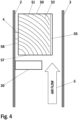
- Figure 4 illustrates a partial side view of one embodiment of an electric drive device cabinet installation according to the present invention.
- a cabinet back wall 2 and a cabinet door 3 of the presented electric drive device cabinet are shown.
- a blocking device 30, such as e.g. a cable duct 30, and an automation device 50 are illustrated.
- the automation device 50 according to the presented embodiment comprises a front panel frame 55 arranged in the front of said automation device 50.
- the other installation devices and cable ducts of the electric drive device cabinet installation are not shown.
- the cables of the electric drive device cabinet installation are not shown.
- Figure 4 presents an example of installation in which said automation device 50 is mounted to a DIN rail 4 arranged in the cabinet back wall 2. Said automation device 50 is installed on top of said blocking device 30.
- the cooling may be arranged by natural convection or with fans both causing airflow from bottom to top, the airflow indicated with an arrow and a reference number 5.
- the blocking device 30 is partially blocking the cooling airflow 5 from the automation device 50 according to the presented embodiment.
- the problem of the prior art electric drive device cabinet design is the blocking effect of airflow by a partially blocking device 30, in Figure 4 said cable duct 30, which prevents uniform airflow to the automation device 20.
- the enclosure of the automation device 50 comprises a multitude of curved heat sink fins 51, 52 arranged on at least one cockled side face of the enclosure of said automation device 50, said heat sink fins 51, 52 along said cockled side face extending from a first end side 57 of the automation device 50 to a second end side 58 of the automation device 50, said first end side 57 and said second end side 58 being neighboring end sides 57, 58, said first end side 57 joining said second end side 58.
- Said at least one cockled side face of the enclosure of said automation device 50 joins both of said first end side 57 and said second end side 58.
- the enclosure of the automation device 50 acts as an external passive heat sink, i.e.
- thermal energy is conducted to the thermally conducting enclosure of the automation device 50, which acts as a heat sink.
- the enclosure of the automation device 50 may be made from aluminium or from any other material having a good thermal conductivity, e.g. from a material comprising aluminium, aluminium alloy, magnesium, copper, brass, plastic, polymer, polymer alloy or synthetic resin.
- said curved heat sink fins 51, 52 of the enclosure do not extend all the way to the front panel frame 55 of the automation device 50.
- Said curved heat sink fins 51, 52 increase the thermal efficiency, i.e. cooling efficiency, of the automation device 50.
- Said heat sink fins 51, 52 direct the airflow from the front of the automation device 50 towards the back of the automation device 50 thereby efficiently cooling a larger portion of said enclosure of the automation device 50.
- Said curved heat sink fins 51, 52 may be arranged on one or both cockled side faces of the enclosure of said automation device 50.
- the automation device 50 comprises a front panel frame 55 arranged in the front of said automation device 50.
- the front part the automation device 50 is set in between two side faces of the enclosure so that said two side faces extend all the way to the front of said automation device 50.
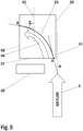
- FIG. 5 illustrates the operation principle of one embodiment of an automation device for an electric drive device according to the present invention.
- an automation device is indicated with a reference number 50 and the airflow inside an electric drive device cabinet is indicated with an arrow and a reference number 5.
- a blocking device 30, such as e.g. a cable duct 30, partially blocking the cooling airflow from the automation device 50 is illustrated.
- the enclosure of the automation device 50 comprises a multitude of curved heat sink fins 53 arranged on at least one cockled side face of the enclosure of said automation device 50, said heat sink fins 53 along said cockled side face extending from a first end side 57 of the automation device 50 to a second end side 58 of the automation device 50, said first end side 57 and said second end side 58 being neighboring end sides 57, 58, said first end side 57 joining said second end side 58.
- Said at least one cockled side face of the enclosure of said automation device 50 joins both of said first end side 57 and said second end side 58.
- Said multitude of curved heat sink fins 53 direct the airflow from the front of the automation device 50 towards the back of the automation device 50 thereby efficiently cooling a larger portion of said enclosure of the automation device 50.
- FIG 5 only one curved heat sink fin 53 of said multitude of curved heat sink fins 53 is shown.
- angle of incidence in this application it is meant to refer to an angle defined on a plane of a side face of the enclosure of said automation device 50 as the angle ⁇ between a line parallel to the front side 56 of the automation device 50 and the inclination of the heatsink fin 53 at said first end side 57 of the automation device 50.
- the automation device 50 is installed upright and an upright line 41 parallel to the front side 56 of the automation device 50 is shown as a dashed line marked with a reference number 41.
- an airflow 5 entering from the bottom upwards meets the first end side 57 of the automation device 50 at the point A in the angle of incidence, i.e. in the angle ⁇ .
- the point A also indicates the point in which the entering airflow 5 meets the heatsink fin 53, i.e. at the beginning of the heatsink fin 53.
- the angle of incidence ⁇ is selected to be small enough to avoid turbulence and to maximize the airflow going into the area of said multitude of curved heat sink fins 53, i.e. into the heatsink area.
- the angle of incidence ⁇ is selected to be between 0 degrees and 30 degrees (0° to 30°).
- the angle of incidence ⁇ is selected to be between 10 degrees and 15 degrees (10° to 15°).
- turning angle in this application it is meant to refer to an angle defined on a plane of a side face of the enclosure of said automation device 50 as the angle ⁇ between a line parallel to said second end side 58 of the automation device 50 and the inclination of the heatsink fin 53 at the second end side 58 of the automation device 50.
- the automation device 50 is installed upright and an upright line 42 parallel to the second end side 58 of the automation device 50 is shown as a dashed line marked with a reference number 42.
- the directed airflow 40 meets the second end side 58 of the automation device 50 at the point B in the turning angle, i.e. in the angle ⁇ .
- the point B also indicates the point in which the directed airflow 40 leaves the heatsink fin 53, i.e. at the end of the heatsink fin 53.
- the turning angle ⁇ is selected to be large enough to maximize the effective airflow in the area of said multitude of curved heat sink fins 53, i.e. in the heatsink area.
- the turning angle ⁇ is selected to be between 60 degrees and 90 degrees (60° to 90°).
- the turning angle ⁇ is selected to be between 75 degrees and 85 degrees (75° to 85°).
- the said multitude of curved heat sink fins 53 direct the airflow along the thermally conducting enclosure of said automation device 50.
- the thermal energy from said automation device 50 is conducted to the aluminium enclosure of the device, where said multitude of curved heat sink fins 53 release thermal energy to the cooling airflow along the thermally conducting enclosure.
- FIG. 6 illustrates a partial side view of another embodiment of an electric drive device cabinet installation according to the present invention.
- a cabinet back wall 2 and a cabinet door 3 of the presented electric drive device cabinet are shown.
- a blocking device 30, such as e.g. a cable duct 30, and an automation device 50 are illustrated.
- the automation device 50 according to the presented another embodiment comprises a front panel frame 55 arranged in the front of said automation device 50.
- the other installation devices and cable ducts of the electric drive device cabinet installation are not shown.
- the cables of the electric drive device cabinet installation are not shown.
- Figure 6 presents an example of installation in which said automation device 50 is mounted to a DIN rail 4 arranged in the cabinet back wall 2. Said automation device 50 is installed on top of said blocking device 30.
- the cooling may be arranged by natural convection or with fans both causing airflow from bottom to top, the airflow indicated with an arrow and a reference number 5.
- the blocking device 30 is partially blocking the cooling airflow 5 from the automation device 50 according to the presented another embodiment.
- the enclosure of the automation device 50 comprises a multitude of curved heat sink fins 61, 62 arranged on at least one cockled side face of the enclosure of said automation device 50, said heat sink fins 61, 62 along said cockled side face extending from a first end side 57 of the automation device 50 to a second end side 58 of the automation device 50, said first end side 57 and said second end side 58 being neighboring end sides 57, 58, said first end side 57 joining said second end side 58.
- Said at least one cockled side face of the enclosure of said automation device 50 joins both of said first end side 57 and said second end side 58.
- the curved heat sink fins 61, 62 of the enclosure extend all the way to the front panel frame 55 of the automation device 50.
- Said curved heat sink fins 61, 62 may be arranged on one or both cockled side faces of the enclosure of said automation device 50.
- the automation device 50 comprises a front panel frame 55 arranged in the front of said automation device 50.
- the front part the automation device 50 is set in between two side faces of the enclosure so that said faces as well as said curved heat sink fins extend all the way to the front of said automation device 50.
- FIG 7 illustrates a partial side view of a third embodiment of an electric drive device cabinet installation according to the present invention.
- a cabinet back wall 2 and a cabinet door 3 of the presented electric drive device cabinet are shown.
- a blocking device 30, such as e.g. a cable duct 30, and an automation device 70 are illustrated.
- the automation device 70 according to the presented third embodiment comprises a front panel frame 75 arranged in the front of said automation device 70.
- the other installation devices and cable ducts of the electric drive device cabinet installation are not shown.
- the cables of the electric drive device cabinet installation are not shown.
- Figure 7 presents an example of installation in which said automation device 70 is mounted directly to the cabinet back wall 2. Said automation device 70 is installed on top of said blocking device 30.
- the cooling may be arranged by natural convection or with fans both causing airflow from bottom to top, the airflow indicated with an arrow and a reference number 5.
- the blocking device 30 is partially blocking the cooling airflow 5 from the automation device 70 according to the presented third embodiment.
- the enclosure of the automation device 70 comprises a multitude of curved heat sink fins 71, 72 arranged on at least one cockled side face of the enclosure of said automation device 70, said heat sink fins 71, 72 along said cockled side face extending from a first end side 57 of the automation device 70 to a second end side 58 of the automation device 70, said first end side 57 and said second end side 58 being neighboring end sides 57, 58, said first end side 57 joining said second end side 58.
- Said at least one cockled side face of the enclosure of said automation device 70 joins both of said first end side 57 and said second end side 58.
- the enclosure of the automation device 70 acts as an external passive heat sink, i.e.
- thermal energy is conducted to the thermally conducting enclosure of the automation device 70, which acts as a heat sink.
- the enclosure of the automation device 70 may be made from aluminium or from any other material having a good thermal conductivity, e.g. from a material comprising aluminium, aluminium alloy, magnesium, copper, brass, plastic, polymer, polymer alloy or synthetic resin.
- the curved heat sink fins 71, 72 of the enclosure do not extend all the way to the front panel frame 75 of the automation device 70.
- said curved heat sink fins 71, 72 of the enclosure do not extend all the way to the back of said automation device 70.
- Said curved heat sink fins 71, 72 may be arranged on one or both cockled side faces of the enclosure of said automation device 70.
- the automation device 70 comprises a front panel frame 75 arranged in the front of said automation device 70.
- the front part the automation device 70 is set in between two side faces of the enclosure so that said faces extend all the way to the front of said automation device 70.
- FIG 8 illustrates a partial side view of a fourth embodiment of an electric drive device cabinet installation according to the present invention.
- a cabinet back wall 2 and a cabinet door 3 of the presented electric drive device cabinet are shown.
- a blocking device 30, such as e.g. a cable duct 30, and an automation device 70 are illustrated.
- the automation device 70 according to the presented fourth embodiment comprises a front panel frame 75 arranged in the front of said automation device 70.
- the other installation devices and cable ducts of the electric drive device cabinet installation are not shown.
- the cables of the electric drive device cabinet installation are not shown.
- Figure 8 presents an example of installation in which said automation device 70 is mounted directly to the cabinet back wall 2. Said automation device 70 is installed on top of said blocking device 30.
- the cooling may be arranged by natural convection or with fans both causing airflow from bottom to top, the airflow indicated with an arrow and a reference number 5.
- the blocking device 30 is partially blocking the cooling airflow 5 from the automation device 70 according to the presented fourth embodiment.
- the enclosure of the automation device 70 comprises a multitude of curved heat sink fins 81, 82 arranged on at least one cockled side face of the enclosure of said automation device 70, said heat sink fins 81, 82 along said cockled side face extending from a first end side 57 of the automation device 70 to a second end side 58 of the automation device 70, said first end side 57 and said second end side 58 being neighboring end sides 57, 58, said first end side 57 joining said second end side 58.
- Said at least one cockled side face of the enclosure of said automation device 70 joins both of said first end side 57 and said second end side 58.
- the curved heat sink fins 81, 82 of the enclosure extend all the way to the front panel frame 75 of the automation device 70.
- said curved heat sink fins 81, 82 of the enclosure do not extend all the way to the back of said automation device 70.
- Said curved heat sink fins 81, 82 may be arranged on one or both cockled side faces of the enclosure of said automation device 70.
- the automation device 70 comprises a front panel frame 75 arranged in the front of said automation device 70.
- the front part the automation device 70 is set in between two side faces of the enclosure so that said faces as well as said curved heat sink fins extend all the way to the front of said automation device 70.
- airflow in an electric drive device cabinet installation is directed to areas, where airflow is otherwise blocked.
- the curved heat sink fins arranged on one or both cockled side faces of the enclosure of said automation device spread the airflow almost uniformly to the heatsink and the blocking effect of a partially blocking device is minimised.
- the solution according to the present invention helps to spread airflow more evenly to the curved heat sink fins and improve thermal performance of the automation device.
- the solution according to the present invention can be used for improving thermal performance of any kind of automation device, such as a control device, a communication device, a monitoring device, a connectivity device or any other automation device.
Landscapes
- Engineering & Computer Science (AREA)
- Microelectronics & Electronic Packaging (AREA)
- Physics & Mathematics (AREA)
- Thermal Sciences (AREA)
- Cooling Or The Like Of Electrical Apparatus (AREA)
Abstract
Description
- The present invention relates to the field of electric drive devices, such as electric drive devices for industrial applications, and automation devices within electric drive device installations, and more particularly to an automation device for an electric drive device and an electric drive device.
- Electric drive devices are widely used for industrial applications, e.g. for providing and controlling electrical power and energy to various public and industrial applications as well as for driving and controlling various public and industrial applications. These applications include devices for transport vehicle engines, different process and manufacturing technological devices, and devices in energy industry as well as industrial electric drives. Electric drive devices may also be referred to as power electronic devices as they typically include a number of power electronic components.
- Within electric drive devices, industrial electric drives are used for various applications, such as transport vehicle engines, different process and manufacturing technological devices and in energy industry. As regards transport devices, electric drives may be used in underground railway service or shipping service, for example. In process and manufacturing technology electric drives may be used e.g. in conveyors, mixers or in paper machines, for instance. In energy industry, electric drives may be used in turbines of wind power industry or in solar power industry, for example.
- Typically, in electric drive device cabinet installations the complexity and power consumption of cabinet installed automation devices is increasing that causes new challenges for thermal management. In typical electric drive device cabinet installations, the space arranged for an automation device is very limited. As the complexity and requirements of automation devices are continuously increasing, thermal design of the automation devices becomes challenging.
- Furthermore, in typical electric drive device cabinet installations there typically is space able ducts and other devices which can partially block the air flow to the automation device, which reduces cooling efficiency.
- In the following, prior art will be described with reference to the accompanying figures, of which:
-
Figure 1 illustrates a front view of an exemplary electric drive device cabinet installation according to the prior art without a cabinet door. -
Figure 2 illustrates a partial side view of another exemplary electric drive device cabinet installation according to the prior art. -
Figure 1 illustrates a front view of an exemplary electric drive device cabinet installation according to the prior art without a cabinet door. The presented exemplary electricdrive device cabinet 1 according to the prior art comprises installation devices 11-17 such asswitches 11, connector modules 12-14 and LED indicator modules 15-17. InFigure 1 only a portion of installation devices 11-17 of an electricdrive device cabinet 1 installation are illustrated as an example. The exemplary electricdrive device cabinet 1 according to the prior art also comprisescable ducts Figure 1 the cables of the electric drive device cabinet installation are not shown. - The presented exemplary electric
drive device cabinet 1 according to the prior art also comprises anautomation device 20.Automation device 20 is mounted in a DIN rail (DIN, Deutsches Institut für Normung) close to other modules or devices. Saidautomation device 20 is installed on top of acable duct 30. - As the cooling airflow in the electric
drive device cabinet 1 flows from the bottom to the top of the in the electricdrive device cabinet 1 thecable duct 30 below theautomation device 20 is partially blocking the cooling airflow from theautomation device 20. Consequently, an adequate cooling of theautomation device 20 in said electricdrive device cabinet 1 installation is therefore not provided. -
Figure 2 illustrates a partial side view of another exemplary electric drive device cabinet installation according to the prior art. InFigure 2 only acabinet back wall 2 and acabinet door 3 of the presented electric drive device cabinet are shown. Also, inFigure 2 only acable duct 30 and anautomation device 20 according to the prior art are illustrated. InFigure 2 the other installation devices and cable ducts of the electric drive device cabinet installation are not shown. Likewise, inFigure 2 the cables of the electric drive device cabinet installation are not shown. -
Figure 2 presents an example of installation in which saidautomation device 20 is mounted to aDIN rail 4 arranged in thecabinet back wall 2. Saidautomation device 20 is installed on top of saidcable duct 30. In the electric drive device cabinet installation, the cooling is typically arranged by natural convection or with fans, which both cause airflow from bottom to top, the airflow indicated with an arrow and areference number 5. - As the cooling airflow in the electric
drive device cabinet 1 flows from the bottom to the top of the in the electricdrive device cabinet 1 thecable duct 30 is partially blocking the cooling airflow from theautomation device 20. The problem of the prior art electric drive device cabinet design is the blocking effect of airflow by a partially blocking device, inFigure 2 saidcable duct 30, which prevents uniform airflow to theautomation device 20. - As illustrated in
Figure 2 , certain areas of the theautomation device 20 lack of adequate airflow and cooling. In the prior art electric drive device cabinet installation the airflow is efficient only in the front part of theautomation device 20 the area of said front part depicted with a dashed line and areference number 21 inFigure 2 . - In the prior art electric drive device cabinet installation a substantial part of the airflow to the back part of the
automation device 20 is blocked by thecable duct 30. InFigure 2 the area of said back part with inefficient cooling is depicted with a dashed line and areference number 22. Consequently, adequate cooling of theautomation device 20 in said electricdrive device cabinet 1 installation is therefore not provided. The presented thermal design problem is even more difficult when other devices are horizontally very close to each other. - The problem with prior art electric drive device cabinet installations and with prior
art automation devices 20 is simply adequate cooling of the automation devices. The complexity and power consumption of cabinet installed automation devices is increasing that causes new challenges for thermal management. In prior art electric drive device cabinet installations the cable ducts and other devices partially block air flow to the automation devices, which reduces cooling efficiency. - Automation devices are typically installed in cabinets, where the space is very limited. As the complexity and requirements of automation devices are continuously increasing, thermal design of the automation devices becomes even more challenging. New developments and requirements, such as digitalization with cloud connectivity and predictive maintenance functions have increased the amount of exchanged data and data processing requirements. New properties and functionalities, such as data analytics, data encryption and high-speed cloud communication generate even more heat in the automation devices, and more efficient cooling is desperately needed.
- One possibility to improve cooling of the automation devices is to use an extra fan. However, but an extra fan reduces the reliability of the electric drive device cabinet installation due to lower reliability and shorter service interval.
- Consequently, there is clearly a need and demand for an automation device for an electric drive device and for an electric drive device that would provide an improved cooling of an automation device in an electric drive device cabinet installation.
- The object of the invention is to introduce an automation device for an electric drive device and to introduce an electric drive device, which provide an improved cooling of an automation device in an electric drive device cabinet installation. Advantageous embodiments are furthermore presented.
- It is brought forward a new automation device for an electric drive device, an enclosure of said automation device comprising an at least one cockled side face comprising a multitude of curved heat sink fins along said cockled side face extending from a first end side of the automation device to a second end side of the automation device, said first end side and said second end side being neighboring end sides, said first end side joining said second end side. Hereby, one or more of the above-mentioned advantages and/or objectives are achieved. These advantages and/or objectives are further facilitated with the additional preferred features and/or steps described in the following.
- In a preferred embodiment, said enclosure is made from aluminium.
- In a preferred embodiment, said enclosure is made from a material having a good thermal conductivity, e.g. from a material comprising aluminium, aluminium alloy, magnesium, copper, brass, plastic, polymer, polymer alloy or synthetic resin.
- In a preferred embodiment, said said multitude of curved heat sink fins are arranged on both cockled side faces of said enclosure.
- In a preferred embodiment, said automation device is mounted to a DIN rail arranged in a cabinet back wall of an electric drive device.
- In a preferred embodiment, said automation device is mounted to a cabinet back wall of an electric drive device, and wherein said curved heat sink fins do not extend all the way to the back of said automation device.
- In a preferred embodiment, the angle of incidence of said curved heat sink fins is between 0 degrees and 30 degrees.
- In a preferred embodiment, the angle of incidence of said curved heat sink fins is between 10 degrees and 15 degrees.
- In a preferred embodiment, the turning angle of said curved heat sink fins is between 60 degrees and 90 degrees.
- In a preferred embodiment, the turning angle of said curved heat sink fins is between 75 degrees and 85 degrees.
- In a preferred embodiment, said automation device comprises a front panel frame arranged in the front of said automation device, and wherein said at least one cockled side face comprises a small space between said curved heat sink fins and said front panel frame.
- In a preferred embodiment, said automation device comprises a front panel frame arranged in the front of said automation device, and wherein said the curved heat sink fins extend all the way to said front panel frame.
- In a preferred embodiment, said automation device comprises a front part set in between two side faces, said two side faces extend all the way to the front of said automation device.
- Furthermore, it is brought forward a new electric drive device, said electric drive device comprising an automation device, said automation device comprising an enclosure and a multitude of curved heat sink fins arranged on at least one side face of said enclosure. Hereby, one or more of the above-mentioned advantages and/or objectives are achieved. These advantages and/or objectives are further facilitated with the additional preferred features and/or steps described in the following.
- In a preferred embodiment, said electric drive device comprises a frequency converter.
- In the following, the present invention will be described in more detail by way of example and with reference to the attached drawings, in which:
-
Figure 1 illustrates a front view of an exemplary electric drive device cabinet installation according to the prior art without a cabinet door. -
Figure 2 illustrates a partial side view of another exemplary electric drive device cabinet installation according to the prior art. -
Figure 3 illustrates a perspective front view of an embodiment of an an automation device according to the present invention. -
Figure 4 illustrates a partial side view of one embodiment of an electric drive device cabinet installation according to the present invention. -
Figure 5 illustrates the operation principle of one embodiment of an automation device for an electric drive device according to the present invention. -
Figure 6 illustrates a partial side view of another embodiment of an electric drive device cabinet installation according to the present invention. -
Figure 7 illustrates a partial side view of a third embodiment of an electric drive device cabinet installation according to the present invention. -
Figure 8 illustrates a partial side view of a fourth embodiment of an electric drive device cabinet installation according to the present invention. - The foregoing aspects, features and advantages of the invention will be apparent from the drawings and the detailed description related thereto.
- The prior art drawings of
Figures 1 to 2 have been presented earlier. In the following, the invention will be described in greater detail by means of preferred embodiments with reference to the accompanying drawings ofFigures 3 to 8 . - The automation device according to one embodiment of the present invention is arranged for an electric drive device and comprises an enclosure and a multitude of curved heat sink fins arranged on at least one cockled side face of said enclosure.
-
Figure 3 illustrates a perspective front view of an embodiment of an an automation device according to the present invention. Theautomation device 50 presented inFigure 3 is designed for installation in an electric drive device cabinet. In the presented embodiment theautomation device 50 comprises afront panel frame 55 arranged in the front of saidautomation device 50. - In the presented embodiment the enclosure of the
automation device 50 comprises a multitude of curvedheat sink fins automation device 50. The enclosure of theautomation device 50 acts as an external passive heat sink, i.e. thermal energy is conducted from the heated components of saidautomation device 50 to the thermally conducting enclosure of theautomation device 50, which acts as a heat sink. - The enclosure of the
automation device 50 may be made from aluminium or from any other material having a good thermal conductivity, e.g. from a material comprising aluminium, aluminium alloy, magnesium, copper, brass, plastic, polymer, polymer alloy or synthetic resin. - In the presented embodiment the curved
heat sink fins automation device 50. The curvedheat sink fins automation device 50 towards the back of theautomation device 50 thereby efficiently cooling a larger portion of said enclosure of theautomation device 50. - In the presented embodiment of
Figure 3 the curvedheat sink fins automation device 50. In an alternative embodiment the curvedheat sink fins automation device 50. In the presented embodiment ofFigure 3 theautomation device 50 comprises afront panel frame 55 arranged in the front of saidautomation device 50. In an alternative embodiment the front part theautomation device 50 is set in between two side faces of the enclosure so that said faces extend all the way to the front of saidautomation device 50. -
Figure 4 illustrates a partial side view of one embodiment of an electric drive device cabinet installation according to the present invention. InFigure 4 only a cabinetback wall 2 and acabinet door 3 of the presented electric drive device cabinet are shown. Also, in the presented embodiment a blockingdevice 30, such as e.g. acable duct 30, and anautomation device 50 are illustrated. Theautomation device 50 according to the presented embodiment comprises afront panel frame 55 arranged in the front of saidautomation device 50. InFigure 4 the other installation devices and cable ducts of the electric drive device cabinet installation are not shown. Likewise, inFigure 4 the cables of the electric drive device cabinet installation are not shown. -
Figure 4 presents an example of installation in which saidautomation device 50 is mounted to aDIN rail 4 arranged in the cabinet backwall 2. Saidautomation device 50 is installed on top of said blockingdevice 30. In the electric drive device cabinet installation, the cooling may be arranged by natural convection or with fans both causing airflow from bottom to top, the airflow indicated with an arrow and areference number 5. - As the
cooling airflow 5 in the electricdrive device cabinet 1 flows from the bottom to the top of the in the electricdrive device cabinet 1 the blockingdevice 30 is partially blocking thecooling airflow 5 from theautomation device 50 according to the presented embodiment. The problem of the prior art electric drive device cabinet design is the blocking effect of airflow by a partially blockingdevice 30, inFigure 4 saidcable duct 30, which prevents uniform airflow to theautomation device 20. - In the presented embodiment the enclosure of the
automation device 50 comprises a multitude of curvedheat sink fins automation device 50, saidheat sink fins first end side 57 of theautomation device 50 to asecond end side 58 of theautomation device 50, saidfirst end side 57 and saidsecond end side 58 being neighboring end sides 57, 58, saidfirst end side 57 joining saidsecond end side 58. Said at least one cockled side face of the enclosure of saidautomation device 50 joins both of saidfirst end side 57 and saidsecond end side 58. The enclosure of theautomation device 50 acts as an external passive heat sink, i.e. thermal energy is conducted to the thermally conducting enclosure of theautomation device 50, which acts as a heat sink. The enclosure of theautomation device 50 may be made from aluminium or from any other material having a good thermal conductivity, e.g. from a material comprising aluminium, aluminium alloy, magnesium, copper, brass, plastic, polymer, polymer alloy or synthetic resin. - In the presented embodiment there is a small space arranged on said at least one cockled side face between said curved
heat sink fins front panel frame 55 of theautomation device 50. So in the presented embodiment the curvedheat sink fins front panel frame 55 of theautomation device 50. Said curvedheat sink fins automation device 50. Saidheat sink fins automation device 50 towards the back of theautomation device 50 thereby efficiently cooling a larger portion of said enclosure of theautomation device 50. - Said curved
heat sink fins automation device 50. In the presented embodiment ofFigure 4 theautomation device 50 comprises afront panel frame 55 arranged in the front of saidautomation device 50. In an alternative embodiment the front part theautomation device 50 is set in between two side faces of the enclosure so that said two side faces extend all the way to the front of saidautomation device 50. -
Figure 5 illustrates the operation principle of one embodiment of an automation device for an electric drive device according to the present invention. InFigure 5 an automation device is indicated with areference number 50 and the airflow inside an electric drive device cabinet is indicated with an arrow and areference number 5. In the presented illustration a blockingdevice 30, such as e.g. acable duct 30, partially blocking the cooling airflow from theautomation device 50 is illustrated. - In the presented embodiment the enclosure of the
automation device 50 comprises a multitude of curvedheat sink fins 53 arranged on at least one cockled side face of the enclosure of saidautomation device 50, saidheat sink fins 53 along said cockled side face extending from afirst end side 57 of theautomation device 50 to asecond end side 58 of theautomation device 50, saidfirst end side 57 and saidsecond end side 58 being neighboring end sides 57, 58, saidfirst end side 57 joining saidsecond end side 58. Said at least one cockled side face of the enclosure of saidautomation device 50 joins both of saidfirst end side 57 and saidsecond end side 58. Said multitude of curvedheat sink fins 53 direct the airflow from the front of theautomation device 50 towards the back of theautomation device 50 thereby efficiently cooling a larger portion of said enclosure of theautomation device 50. InFigure 5 only one curvedheat sink fin 53 of said multitude of curvedheat sink fins 53 is shown. - In
Figure 5 the directed airflow is indicated with an arrow and a reference number 40. InFigure 5 there are also depicted two angles for said multitude of curvedheat sink fins 53, namely an angle of incidence α and a turning angle β. - When referring to the term "angle of incidence", in this application it is meant to refer to an angle defined on a plane of a side face of the enclosure of said
automation device 50 as the angle α between a line parallel to the front side 56 of theautomation device 50 and the inclination of theheatsink fin 53 at saidfirst end side 57 of theautomation device 50. In the embodiment ofFigure 5 theautomation device 50 is installed upright and anupright line 41 parallel to the front side 56 of theautomation device 50 is shown as a dashed line marked with areference number 41. As shown inFigure 5 , anairflow 5 entering from the bottom upwards meets thefirst end side 57 of theautomation device 50 at the point A in the angle of incidence, i.e. in the angle α. In the embodiment shown onFigure 5 , the point A also indicates the point in which the enteringairflow 5 meets theheatsink fin 53, i.e. at the beginning of theheatsink fin 53. The angle of incidence α is selected to be small enough to avoid turbulence and to maximize the airflow going into the area of said multitude of curvedheat sink fins 53, i.e. into the heatsink area. In an embodiment of the present invention the angle of incidence α is selected to be between 0 degrees and 30 degrees (0° to 30°). In another embodiment of the present invention the angle of incidence α is selected to be between 10 degrees and 15 degrees (10° to 15°). - When referring to the term "turning angle", in this application it is meant to refer to an angle defined on a plane of a side face of the enclosure of said
automation device 50 as the angle β between a line parallel to saidsecond end side 58 of theautomation device 50 and the inclination of theheatsink fin 53 at thesecond end side 58 of theautomation device 50. In the embodiment ofFigure 5 theautomation device 50 is installed upright and anupright line 42 parallel to thesecond end side 58 of theautomation device 50 is shown as a dashed line marked with areference number 42. As shown inFigure 5 , the directed airflow 40 meets thesecond end side 58 of theautomation device 50 at the point B in the turning angle, i.e. in the angle β. In the embodiment shown onFigure 5 , the point B also indicates the point in which the directed airflow 40 leaves theheatsink fin 53, i.e. at the end of theheatsink fin 53. The turning angle β is selected to be large enough to maximize the effective airflow in the area of said multitude of curvedheat sink fins 53, i.e. in the heatsink area. In an embodiment of the present invention the turning angle β is selected to be between 60 degrees and 90 degrees (60° to 90°). In another embodiment of the present invention the turning angle β is selected to be between 75 degrees and 85 degrees (75° to 85°). - In the presented embodiment the said multitude of curved
heat sink fins 53 direct the airflow along the thermally conducting enclosure of saidautomation device 50. The thermal energy from saidautomation device 50 is conducted to the aluminium enclosure of the device, where said multitude of curvedheat sink fins 53 release thermal energy to the cooling airflow along the thermally conducting enclosure. -
Figure 6 illustrates a partial side view of another embodiment of an electric drive device cabinet installation according to the present invention. InFigure 6 only a cabinetback wall 2 and acabinet door 3 of the presented electric drive device cabinet are shown. Also, in the presented another embodiment a blockingdevice 30, such as e.g. acable duct 30, and anautomation device 50 are illustrated. Theautomation device 50 according to the presented another embodiment comprises afront panel frame 55 arranged in the front of saidautomation device 50. InFigure 6 the other installation devices and cable ducts of the electric drive device cabinet installation are not shown. Likewise, inFigure 6 the cables of the electric drive device cabinet installation are not shown.Figure 6 presents an example of installation in which saidautomation device 50 is mounted to aDIN rail 4 arranged in the cabinet backwall 2. Saidautomation device 50 is installed on top of said blockingdevice 30. - In the electric drive device cabinet installation, the cooling may be arranged by natural convection or with fans both causing airflow from bottom to top, the airflow indicated with an arrow and a
reference number 5. As thecooling airflow 5 in the electricdrive device cabinet 1 flows from the bottom to the top of the in the electricdrive device cabinet 1 the blockingdevice 30 is partially blocking thecooling airflow 5 from theautomation device 50 according to the presented another embodiment. In the presented another embodiment the enclosure of theautomation device 50 comprises a multitude of curvedheat sink fins automation device 50, saidheat sink fins first end side 57 of theautomation device 50 to asecond end side 58 of theautomation device 50, saidfirst end side 57 and saidsecond end side 58 being neighboring end sides 57, 58, saidfirst end side 57 joining saidsecond end side 58. Said at least one cockled side face of the enclosure of saidautomation device 50 joins both of saidfirst end side 57 and saidsecond end side 58. - In the presented another embodiment the curved
heat sink fins front panel frame 55 of theautomation device 50. Said curvedheat sink fins automation device 50. In the presented another embodiment ofFigure 6 theautomation device 50 comprises afront panel frame 55 arranged in the front of saidautomation device 50. In an alternative embodiment the front part theautomation device 50 is set in between two side faces of the enclosure so that said faces as well as said curved heat sink fins extend all the way to the front of saidautomation device 50. -
Figure 7 illustrates a partial side view of a third embodiment of an electric drive device cabinet installation according to the present invention. InFigure 7 only a cabinetback wall 2 and acabinet door 3 of the presented electric drive device cabinet are shown. Also, in the presented third embodiment a blockingdevice 30, such as e.g. acable duct 30, and anautomation device 70 are illustrated. Theautomation device 70 according to the presented third embodiment comprises afront panel frame 75 arranged in the front of saidautomation device 70. InFigure 7 the other installation devices and cable ducts of the electric drive device cabinet installation are not shown. Likewise, inFigure 7 the cables of the electric drive device cabinet installation are not shown.Figure 7 presents an example of installation in which saidautomation device 70 is mounted directly to the cabinet backwall 2. Saidautomation device 70 is installed on top of said blockingdevice 30. - In the electric drive device cabinet installation, the cooling may be arranged by natural convection or with fans both causing airflow from bottom to top, the airflow indicated with an arrow and a
reference number 5. As thecooling airflow 5 in the electricdrive device cabinet 1 flows from the bottom to the top of the in the electricdrive device cabinet 1 the blockingdevice 30 is partially blocking thecooling airflow 5 from theautomation device 70 according to the presented third embodiment. - In the presented third embodiment the enclosure of the
automation device 70 comprises a multitude of curvedheat sink fins 71, 72 arranged on at least one cockled side face of the enclosure of saidautomation device 70, saidheat sink fins 71, 72 along said cockled side face extending from afirst end side 57 of theautomation device 70 to asecond end side 58 of theautomation device 70, saidfirst end side 57 and saidsecond end side 58 being neighboring end sides 57, 58, saidfirst end side 57 joining saidsecond end side 58. Said at least one cockled side face of the enclosure of saidautomation device 70 joins both of saidfirst end side 57 and saidsecond end side 58. The enclosure of theautomation device 70 acts as an external passive heat sink, i.e. thermal energy is conducted to the thermally conducting enclosure of theautomation device 70, which acts as a heat sink. The enclosure of theautomation device 70 may be made from aluminium or from any other material having a good thermal conductivity, e.g. from a material comprising aluminium, aluminium alloy, magnesium, copper, brass, plastic, polymer, polymer alloy or synthetic resin. - In the presented third embodiment there is a small space arranged on said at least one cockled side face between said curved
heat sink fins 71, 72 and saidfront panel frame 75 of theautomation device 70. So in the presented third embodiment the curvedheat sink fins 71, 72 of the enclosure do not extend all the way to thefront panel frame 75 of theautomation device 70. In the presented third embodiment said curvedheat sink fins 71, 72 of the enclosure do not extend all the way to the back of saidautomation device 70. - Said curved
heat sink fins 71, 72 increase the thermal efficiency, i.e. cooling efficiency, of theautomation device 70. Saidheat sink fins 71, 72 direct the airflow from the front of theautomation device 70 towards the back of theautomation device 70 thereby efficiently cooling a larger portion of said enclosure of theautomation device 70. - Said curved
heat sink fins 71, 72 may be arranged on one or both cockled side faces of the enclosure of saidautomation device 70. In the presented third embodiment ofFigure 7 theautomation device 70 comprises afront panel frame 75 arranged in the front of saidautomation device 70. In an alternative embodiment the front part theautomation device 70 is set in between two side faces of the enclosure so that said faces extend all the way to the front of saidautomation device 70. -
Figure 8 illustrates a partial side view of a fourth embodiment of an electric drive device cabinet installation according to the present invention. InFigure 8 only a cabinetback wall 2 and acabinet door 3 of the presented electric drive device cabinet are shown. Also, in the presented fourth embodiment a blockingdevice 30, such as e.g. acable duct 30, and anautomation device 70 are illustrated. Theautomation device 70 according to the presented fourth embodiment comprises afront panel frame 75 arranged in the front of saidautomation device 70. InFigure 8 the other installation devices and cable ducts of the electric drive device cabinet installation are not shown. Likewise, inFigure 8 the cables of the electric drive device cabinet installation are not shown.Figure 8 presents an example of installation in which saidautomation device 70 is mounted directly to the cabinet backwall 2. Saidautomation device 70 is installed on top of said blockingdevice 30. - In the electric drive device cabinet installation, the cooling may be arranged by natural convection or with fans both causing airflow from bottom to top, the airflow indicated with an arrow and a
reference number 5. As thecooling airflow 5 in the electricdrive device cabinet 1 flows from the bottom to the top of the in the electricdrive device cabinet 1 the blockingdevice 30 is partially blocking thecooling airflow 5 from theautomation device 70 according to the presented fourth embodiment. In the presented fourth embodiment the enclosure of theautomation device 70 comprises a multitude of curvedheat sink fins automation device 70, saidheat sink fins first end side 57 of theautomation device 70 to asecond end side 58 of theautomation device 70, saidfirst end side 57 and saidsecond end side 58 being neighboring end sides 57, 58, saidfirst end side 57 joining saidsecond end side 58. Said at least one cockled side face of the enclosure of saidautomation device 70 joins both of saidfirst end side 57 and saidsecond end side 58. - In the presented fourth embodiment the curved
heat sink fins front panel frame 75 of theautomation device 70. In the presented fourth embodiment said curvedheat sink fins automation device 70. Said curvedheat sink fins automation device 70. In the presented fourth embodiment ofFigure 8 theautomation device 70 comprises afront panel frame 75 arranged in the front of saidautomation device 70. In an alternative embodiment the front part theautomation device 70 is set in between two side faces of the enclosure so that said faces as well as said curved heat sink fins extend all the way to the front of saidautomation device 70. - With the help of the solution according to the present invention airflow in an electric drive device cabinet installation is directed to areas, where airflow is otherwise blocked. In the solution according to the present invention the curved heat sink fins arranged on one or both cockled side faces of the enclosure of said automation device spread the airflow almost uniformly to the heatsink and the blocking effect of a partially blocking device is minimised.
- The solution according to the present invention helps to spread airflow more evenly to the curved heat sink fins and improve thermal performance of the automation device.
- The solution according to the present invention can be used for improving thermal performance of any kind of automation device, such as a control device, a communication device, a monitoring device, a connectivity device or any other automation device.
- The solution according to the present invention proposes a curved heatsink fin design that directs airflow to the areas of an automation device, where airflow is otherwise blocked. The solution according to the present invention provides an elegant, inexpensive, and effective solution without additional extra components.
- It is to be understood that the above description and the accompanying Figures are only intended to teach the best way known to the inventors to make and use the invention. It will be apparent to a person skilled in the art that the inventive concept can be implemented in various ways. The above-described embodiments of the invention may thus be modified or varied, without departing from the invention, as appreciated by those skilled in the art in light of the above teachings. It is therefore to be understood that the invention and its embodiments are not limited to the examples described above but may vary within the scope of the claims and their equivalents.
Claims (15)
- An automation device (50, 70) for an electric drive device, wherein an enclosure of said automation device (50, 70) comprises an at least one cockled side face comprising a multitude of curved heat sink fins (51 - 53, 61, 62, 71, 72, 81, 82) along said cockled side face extending from a first end side (57) of the automation device (50, 70) to a second end side (58) of the automation device (50, 70), said first end side (57) and said second end side (58) being neighboring end sides (57, 58), said first end side (57) joining said second end side (58).
- An automation device (50, 70) according to claim 1, wherein said enclosure is made from aluminium.
- An automation device (50, 70) according to claim 1, wherein said enclosure is made from a material having a good thermal conductivity, e.g. from a material comprising aluminium, aluminium alloy, magnesium, copper, brass, plastic, polymer, polymer alloy or synthetic resin.
- An automation device (50, 70) according to any of the claims 1-3, wherein said multitude of curved heat sink fins (51-53, 61, 62, 71, 72, 81, 82) are arranged on both cockled side faces of said enclosure.
- An automation device (50) according to any of the claims 1-4, wherein said automation device (50) is mounted to a DIN rail (4) arranged in a cabinet back wall (2) of an electric drive device.
- An automation device (70) according to any of the claims 1-4, wherein said automation device (70) is mounted to a cabinet back wall (2) of an electric drive device.
- An automation device (50, 70) according to any of the claims 1-6, wherein the angle of incidence of said curved heat sink fins (51-53, 61, 62, 71, 72, 81, 82) is between 0 degrees and 30 degrees.
- An automation device (50, 70) according to any of the claims 1-6, wherein the angle of incidence of said curved heat sink fins (51-53, 61, 62, 71, 72, 81, 82) is between 10 degrees and 15 degrees.
- An automation device (50, 70) according to any of the claims 1-8, wherein the turning angle of said curved heat sink fins (51-53, 61, 62, 71, 72, 81, 82) is between 60 degrees and 90 degrees.
- An automation device (50, 70) according to any of the claims 1-8, wherein the turning angle of said curved heat sink fins (51-53, 61, 62, 71, 72, 81, 82) is between 75 degrees and 85 degrees.
- An automation device (50, 70) according to any of the claims 1-10, wherein said automation device (50, 70) comprises a front panel frame (55, 75) arranged in the front of said automation device (50, 70), and wherein said at least one cockled side face comprises a small space between said curved heat sink fins (51-53, 71, 72) and said front panel frame (55, 75).
- An automation device (50, 70) according to any of the claims 1-10, wherein said automation device (50, 70) comprises a front panel frame (55, 75) arranged in the front of said automation device (50, 70), and wherein said the curved heat sink fins (53, 61, 62, 81, 82) extend all the way to said front panel frame (55, 75).
- An automation device (50, 70) according to any of the claims 1-12, wherein said automation device (50, 70) comprises a front part set in between two side faces, said two side faces extend all the way to the front of said automation device (50, 70).
- An electric drive device, wherein said electric device comprises an automation device (50, 70) according to any of the claims 1-13.
- An electric drive device according to claim 14, wherein said electric device comprises a frequency converter.
Priority Applications (3)
| Application Number | Priority Date | Filing Date | Title |
|---|---|---|---|
| EP23155780.2A EP4415495A1 (en) | 2023-02-09 | 2023-02-09 | Automation device for an electric drive device and an electric drive device |
| CN202410170517.9A CN118475072A (en) | 2023-02-09 | 2024-02-06 | Automation device for an electric drive device and an electric drive device |
| US18/436,548 US20240276681A1 (en) | 2023-02-09 | 2024-02-08 | Automation Device For An Electric Drive Device And An Electric Drive Device |
Applications Claiming Priority (1)
| Application Number | Priority Date | Filing Date | Title |
|---|---|---|---|
| EP23155780.2A EP4415495A1 (en) | 2023-02-09 | 2023-02-09 | Automation device for an electric drive device and an electric drive device |
Publications (1)
| Publication Number | Publication Date |
|---|---|
| EP4415495A1 true EP4415495A1 (en) | 2024-08-14 |
Family
ID=85222235
Family Applications (1)
| Application Number | Title | Priority Date | Filing Date |
|---|---|---|---|
| EP23155780.2A Pending EP4415495A1 (en) | 2023-02-09 | 2023-02-09 | Automation device for an electric drive device and an electric drive device |
Country Status (3)
| Country | Link |
|---|---|
| US (1) | US20240276681A1 (en) |
| EP (1) | EP4415495A1 (en) |
| CN (1) | CN118475072A (en) |
Citations (4)
| Publication number | Priority date | Publication date | Assignee | Title |
|---|---|---|---|---|
| JPS53107662A (en) * | 1977-03-02 | 1978-09-19 | Nippon Electric Co | Heat dissipation duct for electronic appliances |
| US10080311B1 (en) * | 2017-06-09 | 2018-09-18 | Rockwell Collins, Inc. | Modular enclosure with angled heat sink fins |
| US20180295743A1 (en) * | 2015-03-24 | 2018-10-11 | Coriant Oy | A modular electrical system |
| CN210986861U (en) * | 2019-12-18 | 2020-07-10 | 中国东方电气集团有限公司 | Heat management structure suitable for ship electric drive frequency conversion cabinet |
Family Cites Families (7)
| Publication number | Priority date | Publication date | Assignee | Title |
|---|---|---|---|---|
| US5513071A (en) * | 1994-11-28 | 1996-04-30 | Philips Electronics North America Corporation | Electronics housing with improved heat rejection |
| FI974293A0 (en) * | 1997-11-21 | 1997-11-21 | Muuntolaite Oy | Kylelement Foer ojaemnt foerdelad vaermebelastning |
| US7198094B2 (en) * | 2003-06-20 | 2007-04-03 | Hewlett-Packard Development Company, L.P. | Finned device for removing heat from an electronic component |
| GB2503407B (en) * | 2011-10-10 | 2015-12-09 | Control Tech Ltd | Barrier device |
| CN104519713B (en) * | 2013-09-29 | 2017-08-25 | 华为技术有限公司 | Heat abstractor |
| WO2019118352A1 (en) * | 2017-12-11 | 2019-06-20 | Schlumberger Technology Corporation | Air cooled variable-frequency drive |
| EP3954184B1 (en) * | 2019-04-10 | 2024-06-05 | Sew-Eurodrive GmbH & Co. KG | Electrical device with housing part |
-
2023
- 2023-02-09 EP EP23155780.2A patent/EP4415495A1/en active Pending
-
2024
- 2024-02-06 CN CN202410170517.9A patent/CN118475072A/en active Pending
- 2024-02-08 US US18/436,548 patent/US20240276681A1/en active Pending
Patent Citations (4)
| Publication number | Priority date | Publication date | Assignee | Title |
|---|---|---|---|---|
| JPS53107662A (en) * | 1977-03-02 | 1978-09-19 | Nippon Electric Co | Heat dissipation duct for electronic appliances |
| US20180295743A1 (en) * | 2015-03-24 | 2018-10-11 | Coriant Oy | A modular electrical system |
| US10080311B1 (en) * | 2017-06-09 | 2018-09-18 | Rockwell Collins, Inc. | Modular enclosure with angled heat sink fins |
| CN210986861U (en) * | 2019-12-18 | 2020-07-10 | 中国东方电气集团有限公司 | Heat management structure suitable for ship electric drive frequency conversion cabinet |
Also Published As
| Publication number | Publication date |
|---|---|
| US20240276681A1 (en) | 2024-08-15 |
| CN118475072A (en) | 2024-08-09 |
Similar Documents
| Publication | Publication Date | Title |
|---|---|---|
| CN203896646U (en) | Electronic component and printed circuit board of heating element on cooling printed circuit board | |
| CN104094681B (en) | For the mechanical heat pump of electric housing | |
| CN101513150B (en) | Motor control device | |
| JP5581119B2 (en) | Cooling device, power converter, railway vehicle | |
| JP5794101B2 (en) | Forced air cooling heat sink | |
| US20100302730A1 (en) | Use of vortex generators to improve efficacy of heat sinks used to cool electrical and electro-optical components | |
| CN105005368A (en) | Air cooling device | |
| WO2013080341A1 (en) | Electronic board unit and electronic device | |
| EP4415495A1 (en) | Automation device for an electric drive device and an electric drive device | |
| CN107432100B (en) | Cooling equipment for switchgear air conditioning | |
| JP5962326B2 (en) | Forced air cooling heat sink | |
| JP2025085591A (en) | Energy storage converter and heat dissipation system | |
| CN102594177A (en) | Power module for photovoltaic grid-connected inverter and photovoltaic grid-connected inverter | |
| CN114396662A (en) | Electric control box and air conditioner outdoor unit with same | |
| CN115190734A (en) | Heat sink device | |
| US10251319B2 (en) | Heat radiation apparatus using modular cooling apparatus | |
| EP4002973B1 (en) | Inverter and heat radiation structure thereof | |
| CN102402265B (en) | Container data center and air inlet device thereof | |
| CN106163237A (en) | A kind of heat abstractor and electronic equipment | |
| CN205755244U (en) | Air-cooled, the electricity feedback servosystem of water-cooling of a kind of independent ventiduct | |
| CN202444430U (en) | Photovoltaic grid-connected inverter and power module for same | |
| CN2789708Y (en) | Laminated heat exchanger | |
| CN212461813U (en) | Scraper dehumidification system | |
| CN222967260U (en) | Inverter heat dissipation air duct structure and inverter | |
| CN113163671A (en) | Mining flame-proof type frequency converter box and heat dissipation system thereof |
Legal Events
| Date | Code | Title | Description |
|---|---|---|---|
| PUAI | Public reference made under article 153(3) epc to a published international application that has entered the european phase |
Free format text: ORIGINAL CODE: 0009012 |
|
| STAA | Information on the status of an ep patent application or granted ep patent |
Free format text: STATUS: THE APPLICATION HAS BEEN PUBLISHED |
|
| AK | Designated contracting states |
Kind code of ref document: A1 Designated state(s): AL AT BE BG CH CY CZ DE DK EE ES FI FR GB GR HR HU IE IS IT LI LT LU LV MC ME MK MT NL NO PL PT RO RS SE SI SK SM TR |
|
| STAA | Information on the status of an ep patent application or granted ep patent |
Free format text: STATUS: REQUEST FOR EXAMINATION WAS MADE |
|
| 17P | Request for examination filed |
Effective date: 20240830 |
|
| RBV | Designated contracting states (corrected) |
Designated state(s): AL AT BE BG CH CY CZ DE DK EE ES FI FR GB GR HR HU IE IS IT LI LT LU LV MC ME MK MT NL NO PL PT RO RS SE SI SK SM TR |