EP4415433A2 - Verfahren und vorrichtung zur meldung von leistungsreduzierungsinformationen, endgerätevorrichtung und netzwerkvorrichtung - Google Patents
Verfahren und vorrichtung zur meldung von leistungsreduzierungsinformationen, endgerätevorrichtung und netzwerkvorrichtung Download PDFInfo
- Publication number
- EP4415433A2 EP4415433A2 EP24185587.3A EP24185587A EP4415433A2 EP 4415433 A2 EP4415433 A2 EP 4415433A2 EP 24185587 A EP24185587 A EP 24185587A EP 4415433 A2 EP4415433 A2 EP 4415433A2
- Authority
- EP
- European Patent Office
- Prior art keywords
- information
- mpr
- reporting
- phr
- terminal device
- Prior art date
- Legal status (The legal status is an assumption and is not a legal conclusion. Google has not performed a legal analysis and makes no representation as to the accuracy of the status listed.)
- Pending
Links
Images


Classifications
-
- H—ELECTRICITY
- H04—ELECTRIC COMMUNICATION TECHNIQUE
- H04W—WIRELESS COMMUNICATION NETWORKS
- H04W52/00—Power management, e.g. Transmission Power Control [TPC] or power classes
- H04W52/04—Transmission power control [TPC]
- H04W52/30—Transmission power control [TPC] using constraints in the total amount of available transmission power
- H04W52/36—Transmission power control [TPC] using constraints in the total amount of available transmission power with a discrete range or set of values, e.g. step size, ramping or offsets
- H04W52/365—Power headroom reporting
-
- H—ELECTRICITY
- H04—ELECTRIC COMMUNICATION TECHNIQUE
- H04W—WIRELESS COMMUNICATION NETWORKS
- H04W52/00—Power management, e.g. Transmission Power Control [TPC] or power classes
- H04W52/04—Transmission power control [TPC]
- H04W52/06—TPC algorithms
- H04W52/14—Separate analysis of uplink or downlink
- H04W52/146—Uplink power control
-
- H—ELECTRICITY
- H04—ELECTRIC COMMUNICATION TECHNIQUE
- H04W—WIRELESS COMMUNICATION NETWORKS
- H04W52/00—Power management, e.g. Transmission Power Control [TPC] or power classes
- H04W52/04—Transmission power control [TPC]
- H04W52/54—Signalisation aspects of the TPC commands, e.g. frame structure
-
- H—ELECTRICITY
- H04—ELECTRIC COMMUNICATION TECHNIQUE
- H04W—WIRELESS COMMUNICATION NETWORKS
- H04W72/00—Local resource management
- H04W72/20—Control channels or signalling for resource management
- H04W72/21—Control channels or signalling for resource management in the uplink direction of a wireless link, i.e. towards the network
-
- H—ELECTRICITY
- H04—ELECTRIC COMMUNICATION TECHNIQUE
- H04W—WIRELESS COMMUNICATION NETWORKS
- H04W52/00—Power management, e.g. Transmission Power Control [TPC] or power classes
- H04W52/04—Transmission power control [TPC]
- H04W52/30—Transmission power control [TPC] using constraints in the total amount of available transmission power
- H04W52/36—Transmission power control [TPC] using constraints in the total amount of available transmission power with a discrete range or set of values, e.g. step size, ramping or offsets
- H04W52/367—Power values between minimum and maximum limits, e.g. dynamic range
Definitions
- Embodiments of the present application relate to the technical field of mobile communication, and more particularly, to a method and apparatus for reporting power reduction information, a terminal device and a network device.
- a terminal device reports a power headroom report (PHR) to assist the network side in uplink power control and uplink scheduling.
- PHR power headroom report
- P-MPR power management-maximum power reduction
- Embodiments of the present application provide a method and apparatus for reporting power reduction information, a terminal device and a network device.
- a method for reporting power reduction information including: sending, by a terminal device, a first media access control control element (MAC CE) to a network device, the first MAC CE including P-MPR information of at least one carrier.
- MAC CE media access control control element
- a method for reporting power reduction information including: receiving, by a network device, a first MAC CE sent by a terminal device, the first MAC CE including at least one piece of P-MPR information.
- An apparatus for reporting power reduction information is provided by an embodiment of the present application, applied to a terminal device, including: a sending unit configured to send a first MAC CE to a network device, the first MAC CE including P-MPR information of at least one carrier.
- An apparatus for reporting power reduction information is provided by an embodiment of the present application, applied to a network device, including: a receiving unit configured to receive a first MAC CE sent by a terminal device, the first MAC CE including at least one piece of P-MPR information.
- a terminal device including a processor and a memory.
- the memory is used for storing a computer program
- the processor is used for invoking and running the computer program stored in the memory to execute the method for reporting the power reduction information described above.
- a network device including a processor and a memory.
- the memory is used for storing a computer program
- the processor is used for invoking and running the computer program stored in the memory to execute the method for reporting the power reduction information described above.
- a chip is provided by an embodiment of the present application, used for implementing the methods for reporting the power reduction information described above.
- the chip includes a processor used for invoking and running a computer program from a memory to cause a device having the chip installed thereon to execute the methods for reporting the power reduction information described above.
- a computer readable storage medium is provided by an embodiment of the present application, used for storing a computer program, which causes a computer to execute the methods for reporting the power reduction information described above.
- a computer program product is provided by an embodiment of the present application, including computer program instructions, which cause a computer to execute the methods for reporting the power reduction information described above.
- a computer program is provided by an embodiment of the present application, which, when running on a computer, causes the computer to execute the methods for reporting the power reduction information described above.
- a terminal device reports P-MPR information of at least one carrier to a network side by the first MAC CE (i.e., PHR MAC CE or independent MAC CE), thereby providing a P-MPR reporting mechanism, such that the network side can better understand a power reduction situation of the terminal device and better perform uplink power control and uplink scheduling for the terminal device.
- the first MAC CE i.e., PHR MAC CE or independent MAC CE
- LTE Long Term Evolution
- FDD Frequency Division Duplex
- TDD Time Division Duplex
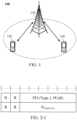
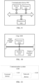
- the communication system 100 may include a network device 110, which may be a device that communicates with a terminal 120 (or referred to as communication terminal, or terminal).
- the network device 110 may provide communication coverage for a specific geographical area, and may communicate with a terminal located within the coverage area.
- the network device 110 may be an Evolutional Node B (eNB or eNodeB) in an LTE system, or a radio controller in a Cloud Radio Access Network (CRAN), or the network device may be a mobile switching center, a relay station, an access point, a vehicle-mounted device, a wearable device, a hub, a switch, a bridge, a router, a network side device in a 5G network, or a network device in a future communication system.
- eNB or eNodeB Evolutional Node B
- CRAN Cloud Radio Access Network
- the communication system 100 further includes at least one terminal 120 located within the coverage area of the network device 110.
- the "terminal” as used herein includes, but is not limited to, an apparatus configured to receive/send communication signals via a wired circuit, for example, via a public switched telephone network (PSTN), a digital subscriber line (DSL), a digital cable, a direct cable; and/or another data connection/network; and/or via a wireless interface, for instance, for a cellular network, a wireless local area network (WLAN), a digital television network such as a handheld digital video broadcasting-handheld (DVB-H) network, a satellite network, and an amplitude modulation - frequency modulation (AM-FM) broadcast transmitter; and/or another terminal; and/or an Internet of Things (IoT) device.
- PSTN public switched telephone network
- DSL digital subscriber line
- AM-FM amplitude modulation - frequency modulation
- IoT Internet of Things
- a terminal configured to communicate via a wireless interface may be referred to as "a wireless communication terminal", “a wireless terminal” or "a mobile terminal".
- An example of the mobile terminal includes, but is not limited to, a satellite or cellular phone; a personal communication system (PCS) terminal capable of combining a cellular radio phone with data processing, facsimile, and data communication abilities; a personal digital assistant (PDA) that may include a radio phone, a pager, internet/intranet access, a Web browser, a memo pad, a calendar, a Global Positioning System (GPS) receiver; and a conventional laptop and/or palmtop receiver or other electronic devices including a radio phone transceiver.
- PCS personal communication system
- PDA personal digital assistant
- GPS Global Positioning System
- the terminal may refer to an access terminal, user equipment (UE), a subscriber unit, a subscriber station, a mobile station, a rover station, a remote station, a remote terminal, a mobile device, a user terminal, a terminal, a wireless communication device, a user agent, or a user apparatus.
- UE user equipment
- the access terminal may be a cellular phone, a cordless phone, a Session Initiation Protocol (SIP) phone, a Wireless Local Loop (WLL) station, a Personal Digital Assistant (PDA), a handheld device with a wireless communication function, a computing device, or other processing devices connected to a wireless modem, a vehicle-mounted device, a wearable device, a terminal in a 5G network, or a terminal in a future evolved Public Land Mobile Network (PLMN).
- SIP Session Initiation Protocol
- WLL Wireless Local Loop
- PDA Personal Digital Assistant
- PLMN Public Land Mobile Network
- D2D device to device communication
- D2D device to device
- the 5G system or 5G network may also be referred to as a new radio (NR) system or a NR network
- FIG. 1 shows one network device and two terminals illustratively.
- the communication system 100 may include multiple network devices, and other numbers of terminals may be included within the coverage area of each network device, which is not limited in the embodiments of the present application.
- the communication system 100 may include other network entities, such as a network controller and a mobile management entity, which is not limited in the embodiments of the present application.
- a device with a communication function in a network/system in the embodiments of the present application may be referred to as a communication device.
- the communication device may include a network device 110 and terminal devices 120 which have communication functions, and the network device 110 and the terminal devices 120 may be the specific devices described above, and will not be described repeatedly herein.
- the communication device may also include other devices in the communication system 100, such as other network entities, such as network controllers and mobile management entities, which is not limited in the embodiments of the present application.
- system and “network” are often used interchangeably herein.
- the term “and/or” herein describes an association relationship between associated objects only, indicating that there may be three relationships, for example, A and/or B may indicate three cases: A alone, both A and B, and B alone.
- the symbol “/” herein generally indicates that there is an “or” relationship between the associated objects before and after "/”.
- 5G Enhance Mobile Broadband
- URLLC Ultra-Reliable and Low-Latency Communication
- mMTC Mass Machine-Type of Communication
- the eMBB aims at enabling users to obtain multimedia contents, services and data, and the demands for the eMBB are growing rapidly.
- the eMBB may be deployed in different scenarios, such as indoors, urban districts, rural areas, and differences in its capabilities and demands are big, it cannot be generalized and must be analyzed in detail in combination with specific deployment scenarios.
- Typical applications of the URLLC include: industrial automation, power automation, telemedicine operation (surgery), traffic safety guarantee, etc.
- Typical characteristics of the mMTC include: high connection density, small data volume, latency-insensitive service, low cost and long service life of modules, etc.
- an LTE base station serves as a master node (MN)
- an NR base station serves as a secondary node (SN)
- SN secondary node
- other DC modes i.e., NE-DC, 5GC-EN-DC and NR DC
- an NR base station serves as an MN
- an eLTE base station serves as an SN and is connected to a 5GC core network.
- an eLTE base station serves as an MN, and an NR base station serves as an SN and is connected to a 5GC core network.
- an NR base station serves as an MN, and an NR base station serves as an SN and is connected to a 5GC core network.
- the technical solutions of the embodiments of the present application can be applied not only to a dual connectivity architecture (such as an MR-DC architecture), but also to a multiple connectivity (MC) architecture.
- the MC architecture may be an MR-MC architecture.
- RRC_INACTIVE state a new radio resource control (RRC) state, i.e., RRC_INACTIVE state, is defined for 5G. This state is different from an RRC_IDLE state and an RRC_ACTIVE state.
- a terminal device reports a PHR to a network side, so as to assist the network side in better uplink data scheduling and uplink power control.
- the PHR can be calculated, as described above, based on actual transmission or reference virtual transmission. Specifically, the PHR being calculated based on the actual transmission means that the PHR is calculated according to actually transmitted PUSCH, or PUSCH and PUCCH, or SRS. The PHR being calculated based on the reference virtual transmission means that the PHR is calculated according to a reference format. It should be noted that reference formats of different types of PHR are different.
- the terminal device reports a PHR of a single cell, as shown in FIG. 2-1 .
- the terminal device will report PHRs of all active cells of the terminal device, including active cells at the MCG side and active cells at the SCG side, of the terminal device.
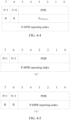
- FIG. 2-2 shows a format of a PHR reported to a NR base station.
- C i (1 ⁇ i ⁇ 7) corresponds to an index of one serving cell
- C 1 to C 7 correspond to indexes of seven serving cells respectively.
- a value of Ci is used to indicate whether a PHR of the corresponding serving cell is reported.
- the PHR of each serving cell consists of 2 bytes, including the following information fields: a P field, a V field, a PHR field and a PCMAX field, where information in the P field is used to indicate whether P-MPR is applied.
- Information in the V field is used to indicate whether the PHR is calculated based on actual transmission or a reference format.
- Information in the PHR field is a PHR (also referred to as PH for short), where the type of the PHR may be type1 PHR, type2 PHR or type3 PHR, but are not limited thereto, and the type of the PHR may also be enhanced, such as typex PHR.
- Information in the PCMAX field is P CMAX,f,c .
- the PCMAX field is optional.
- P CMAX,f,c In the case that the information in the V field indicates that the PHR is calculated based on the actual transmission, P CMAX,f,c needs to be carried, and in the case that the information in the V field indicates that the PHR is calculated based on the reference format, P CMAX,f,c does not need to be carried (i.e., P CMAX,f,c is omitted and is not transmitted).
- the concept of P-MPR is introduced.
- a value of the P-MPR is determined by the terminal device itself and is not restricted by the network side, so the network side does not know the value of the P-MPR.
- the P field is considered in the power headroom report, and the information in the P field is used to indicate whether the P-MPR is applied.
- the value of the P-MPR may be very large, so the network side demands the terminal device to report the value of the P-MPR, that is, how much power is reduced by the terminal device specifically. Therefore, the following technical solution of an embodiment of the present application is proposed.
- the P-MPR reporting can be applied to service cells of FR2, but are not limited thereto, and the P-MPR reporting can also be applied to service cells in other frequency band ranges.
- FIG. 3 is a schematic flowchart of a method for reporting power reduction information in accordance with an embodiment of the present application. As shown in FIG. 3 , the method for reporting the power reduction information includes the following act 301.
- a terminal device sends a first MAC CE to a network device, the first MAC CE including P-MPR information of at least one carrier.
- the terminal device sends the first MAC CE to the network device, and accordingly, the network device receives the first MAC CE sent by the terminal device.
- the network device may be a base station, such as a gNB.
- the first MAC CE may be a PHR MAC CE or an independent MAC CE (or referred to as a PHR-specific MAC CE).
- the specific implementation of the first MAC CE will be described below.
- the terminal device reports P-MPR information of one or more carriers through the existing PHR MAC CE.
- the P-MPR information is specifically P-MPR reporting index information, where the P-MPR reporting index information is used to determine a value range of the P-MPR reporting (referred to as value information of P-MPR for short).
- the PHR MAC CE includes power information of the one or more carriers, wherein the power information includes:
- Information in the V field i.e., the second information
- the PHR is calculated based on actual transmission or a reference format.
- Information in the PHR field i.e., the third information
- the type of the PHR may be type1 PHR, type2 PHR or type3 PHR, but is not limited thereto, and the type of the PHR can also be enhanced, such as typex PHR.
- carrier in an embodiment of the present application can also be replaced by “serving cell” or "cell”.
- first type of power headroom in an embodiment of the present application can also be replaced by “type1 PHR", where “type1 PHR” can also be referred to as “type1 PH” for short.
- second type of power headroom in an embodiment of the present application can also be replaced by "type2 PHR", where “type2 PHR” can also be referred to as “type2 PH” for short.
- third type of power headroom in an embodiment of the present application can also be replaced by "type3 PHR", where “type3 PHR” can also be referred to as “type3 PH” for short.
- the first information is P indication information
- the second information is V indication information
- the third information is PHR
- the fourth information is P CMAX,f,c .
- power headroom information of one carrier includes P indication information, V indication information, PHR and P CMAX,f,c .
- the power information includes only the first information, the second information and the third information.
- the first information is P indication information
- the second information is V indication information
- the third information is PHR.
- power headroom information of one carrier includes P indication information, V indication information and PHR.
- the power information includes fourth information and fifth information in addition to the first information, the second information and the third information, wherein the fourth information is used to indicate the maximum transmit power of the terminal device; and the fifth information is used to indicate the value range of the P-MPR reporting.
- the first information is P indication information
- the second information is V indication information
- the third information is PHR
- the fourth information is P CMAX,f,c
- the fifth information is P-MPR reporting index, wherein the P-MPR reporting index is used to determine the value range of the P-MPR reporting.
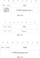
- the fourth information occupies 6 bits of a first byte
- the fifth information occupies 2 bits of the first byte.
- power headroom information of one carrier includes P indication information, V indication information, PHR, P CMAX,f,c and P-MPR reporting index.
- P CMAX,f,c occupies 6 bits of one byte, and the P-MPR reporting index occupies the remaining 2 bits of the byte.
- the fourth information occupies 6 bits of the first byte
- the fifth information occupies N1 bits of a second byte, wherein N1 is an integer greater than or equal to 2 and less than or equal to 8.
- power headroom information of one carrier includes P indication information, V indication information, PHR, P CMAX,f, and P-MPR reporting index.
- P CMAX,f,c occupies 6 bits of one byte
- the P-MPR reporting index occupies 8 bits of another byte.
- the power information includes fifth information in addition to the first information, the second information and the third information, wherein the fifth information is used to indicate the value range of the P-MPR reporting.
- the first information is P indication information
- the second information is V indication information
- the third information is PHR
- the fifth information is P-MPR reporting index, wherein the P-MPR reporting index is used to determine the value range of the P-MPR reporting.
- the fifth information occupies N2 bits of the first byte, and N2 is an integer greater than or equal to 2 and less than or equal to 8.
- power headroom information of one carrier includes P indication information, V indication information, PHR and P-MPR reporting index.
- the P-MPR reporting index occupies 8 bits of one byte
- the P-MPR reporting index occupies 6 bits of one byte. It should be noted that the number of bits that may be occupied by the P-MPR reporting index is not limited.
- the power information includes fifth information in addition to the first information, the second information and the third information, and the fifth information includes first sub-information and second sub-information, wherein the first sub-information is used to indicate a first value range of the P-MPR and the second sub-information is used to indicate a second value range of the P-MPR within the first value range.
- the first information is P indication information
- the second information is V indication information
- the third information is PHR
- the first sub-information is P-MPR reporting index x
- the second sub-information is P-MPR reporting index y
- the P-MPR reporting index x is used to determine the first value range (i.e., large granularity range) of the P-MPR reporting
- the P-MPR reporting index y is used to determine the second value range (i.e., small granularity range) of the P-MPR reporting within the first value range.
- the first sub-information occupies N3 bits of the first byte
- the second sub-information occupies N4 bits of the first byte, both N3 and N4 being integers greater than or equal to 2, and the sum of N3 and N4 being less than or equal to 8.
- power headroom information of one carrier includes P indication information, V indication information, PHR, P-MPR reporting index x and p-MPR reporting index y.
- the P-MPR reporting index x occupies 2 bits of one byte, and the P-MPR reporting index y occupies the remaining 6 bits of the byte. It should be noted that the number of bits that may be occupied by the P-MPR reporting index x and P-MPR reporting index y is not limited.
- the P-MPR reporting index x indicates a power reduction value in the large granularity range
- the P-MPR reporting index y indicates a power reduction value in a further fine granularity range in the large granularity range indicated by the P-MPR reporting index x.
- the power information in order to ensure that overhead of the first MAC CE remains unchanged, includes one of fourth information and fifth information in addition to the first information, the second information and the third information, wherein the fourth information is used to indicate the maximum transmit power of the terminal device, and the fifth information is used to indicate the value range of the P-MPR reporting.
- the first information is P indication information
- the second information is V indication information
- the third information is PHR
- the fourth information is P CMAX,f,c
- the fifth information is P-MPR reporting index, wherein the P-MPR reporting index is used to determine the value range of the P-MPR reporting.
- the terminal device will not report P CMAX,f,c and the P-MPR reporting index simultaneously.
- the terminal device receives first indication information sent by the network device, the first indication information being used to indicate whether the terminal device reports the fourth information or the fifth information.
- the PHR MAC CE includes the fourth information.
- the network side instructs the terminal device to report P CMAX,f,c , and power headroom information of one carrier includes P indication information, V indication information, PHR and P CMAX,f,c .
- P CMAX,f,c occupies 6 bits of one byte.
- the PHR MAC CE includes the fifth information.
- the network side instructs the terminal device to report a P-MPR reporting index
- power headroom information of one carrier includes P indication information, V indication information, PHR and P-MPR reporting index.
- the P-MPR reporting index occupies 8 bits of one byte. It should be noted that the number of bits occupied by the P-MPR reporting index is not limited (8 bits are taken as an example in FIG. 5-2 ).
- the power information reported by the terminal device only includes one of the fourth information and the fifth information
- the power information also includes sixth information used for indicating whether the power information carries the fourth information or the fifth information.
- the terminal device can dynamically indicate in the reported power information whether the power information contains P CMAX,f,c or the P-MPR reporting index.
- the sixth information is a flag (F), through which the terminal device indicates whether the currently reported power information carries P CMAX,f,c or the P-MPR reporting index.
- the number of bits occupied by the flag and the P-MPR reporting index in FIG. 5-3 is not limited to 1 or 6.
- the number of bits occupied by the flag and the P-MPR reporting index may be preset by the protocol or configured by the network.
- the terminal device reports the P-MPR information of one or more carriers through the newly defined MAC CE.
- the P-MPR information is specifically P-MPR reporting index information, wherein the P-MPR reporting index information is used to determine the value range of the P-MPR reporting.
- the seventh information is a serving cell index
- the fifth information is a P-MPR reporting index, wherein the P-MPR reporting index is used to determine the value range of the P-MPR reporting.
- the first MAC CE contains only the P-MPR reporting index of one carrier (or serving cell).
- the serving cell index and the P-MPR reporting index of one carrier are carried by one byte.
- the serving cell index of one carrier is carried by one byte, and the P-MPR reporting index of this carrier is carried by this byte and another byte.
- the number of bits occupied by the P-MPR reporting index is not limited (in FIG. 6-1 , as an example, partial bits of one byte are occupied; and in FIG. 6-2 , as an example, partial bits of one byte and all bits of another byte are occupied).
- the number of bits occupied by the P-MPR reporting index may be preset by the protocol or configured by the network.
- the serving cell index may be a serving cell index configured by the network side, and further, it may be a serving cell index on FR2 configured by the network side (serving cell indexes are sorted in order from small to large) or an activated serving cell index on FR2 (serving cell indexes are sorted in order from small to large).
- the first MAC CE includes a first bitmap and at least one piece of fifth information, wherein each bit in the first bitmap corresponds to one carrier, and a value of the bit is used to indicate whether the first MAC CE includes the fifth information of the carrier corresponding to the bit, and the fifth information is used to indicate the value range of the P-MPR reporting.
- header information of the first MAC CE carries the first bitmap
- the fifth information is P-MPR reporting index, wherein the P-MPR reporting index is used to determine the value range of the P-MPR reporting.
- the first MAC CE contains P-MPR reporting indexes of multiple carriers (or serving cells).
- the header of the first MAC CE includes the first bitmap, which corresponds to C0, C1, ..., C7 one by one in order from small to large of all serving cell indexes on FR2 configured by the network side.
- the first bits may be fixed 8 bits or 32 bits, or may also be determined by rounding the number of carriers configured on FR2 or the number of carriers activated on FR2 with respect to 8-bits.
- the P-MPR reporting index corresponding to each carrier is carried. It should be noted that the number of bits occupied by the P-MPR reporting index is not limited (in FIG. 6-3 , as an example, all bits of one byte are occupied).
- the triggering of the P-MPR reporting may mean that if the PHR reporting and/or the P-MPR reporting is triggered, then the P-MPR will be triggered for reporting.
- the terminal device sends the first MAC CE to the network device in the case that the PHR reporting and/or the P-MPR reporting is triggered.
- a new trigger event is defined for the P-MPR reporting.
- the P-MPR reporting being triggered includes at least one of:
- the event includes at least one of: a power reduction value being greater than or equal to a first threshold; and a power variation being greater than or equal to a second threshold.
- values of the first threshold and the second threshold may be preset by the protocol or configured by the network.
- a terminal device reports P-MPR information of at least one carrier to a network side through the first MAC CE (i.e., PHR MAC CE or independent MAC CE), thereby providing a P-MPR reporting mechanism, such that the network side can better understand power reduction of the terminal device and better perform uplink power control and uplink scheduling for the terminal device.
- PHR MAC CE i.e., PHR MAC CE or independent MAC CE
- FIG. 7 is a first structure composition schematic diagram of an apparatus for reporting power reduction information in accordance with an embodiment of the present application, which is applied to a terminal device and includes a sending unit 701.
- the sending unit 701 is configured to send a first MAC CE to a network device, the first MAC CE includes P-MPR information of at least one carrier.
- the first MAC CE is a PHR MAC CE
- the PHR MAC CE includes power information of one or more carriers, wherein the power information includes:
- the power information further includes fourth information and fifth information, wherein the fourth information is used to indicate the maximum transmit power of the terminal device; and the fifth information is used to indicate a value range of P-MPR reporting.
- the fourth information occupies 6 bits of a first byte, and the fifth information occupies 2 bits of the first byte; or the fourth information occupies 6 bits of the first byte, and the fifth information occupies N1 bits of a second byte, N1 being an integer greater than or equal to 2 and less than or equal to 8.
- the power information in a case that the first information indicates that the P-MPR is applied to the terminal device, if the second information indicates that the PHR is calculated based on the reference format, the power information further includes fifth information, wherein the fifth information is used to indicate the value range of the P-MPR reporting.
- the fifth information occupies N2 bits of the first byte, N2 being an integer greater than or equal to 2 and less than or equal to 8.
- the power information further includes fifth information, which includes first sub-information and second sub-information, wherein the first sub-information is used to indicate a first value range of the P-MPR; and the second sub-information is used to indicate a second value range of the P-MPR within the first value range.
- the first sub-information occupies N3 bits of the first byte
- the second sub-information occupies N4 bits of the first byte, both N3 and N4 being integers greater than or equal to 2, and the sum of N3 and N4 being less than or equal to 8.
- the power information further includes one of fourth information and fifth information, wherein the fourth information is used to indicate the maximum transmit power of the terminal device, and the fifth information is used to indicate the value range of the P-MPR reporting.
- the apparatus further includes a receiving unit 702.
- the receiving unit 702 is configured to receive first indication information sent by the network device, the first indication information being used to indicate whether the terminal device reports the fourth information or the fifth information.
- the PHR MAC CE includes the fourth information; or if the first indication information indicates that the terminal device reports the fifth information, the PHR MAC CE includes the fifth information.
- the first indication information is used to indicate whether the terminal device reports the fourth information or the fifth information in a case that the second information indicates that the PHR is calculated based on the actual transmission.
- the power information further includes sixth information, which is used to indicate whether the power information carries the fourth information or the fifth information.
- the first MAC CE includes seventh information and fifth information of a carrier, wherein the seventh information is serving cell index; and the fifth information is used to indicate the value range of the P-MPR reporting.
- the first MAC CE includes a first bitmap and at least one piece of fifth information, wherein each bit in the first bitmap corresponds to a carrier, and a value of the bit is used to indicate whether the first MAC CE includes the fifth information of the carrier corresponding to the bit, and the fifth information is used to indicate the value range of the P-MPR reporting.
- the sending unit 701 is configured to send the first MAC CE to the network device in a case that the PHR reporting and/or the P-MPR reporting is triggered.
- the P-MPR reporting being triggered includes at least one of:
- the event includes at least one of:
- FIG. 8 is a second structure composition schematic diagram of an apparatus for reporting power reduction information in accordance with an embodiment of the present application, which is applied to a network device and includes a receiving unit 801.
- the receiving unit 801 is configured to receive a first MAC CE sent by a terminal device, the first MAC CE including at least one piece of P-MPR information.
- the first MAC CE is a PHR MAC CE
- the PHR MAC CE includes power information of one or more carriers, wherein the power information includes:
- the power information further includes fourth information and fifth information, wherein the fourth information is used to indicate the maximum transmit power of the terminal device; and the fifth information is used to indicate a value range of P-MPR reporting.
- the fourth information occupies 6 bits of a first byte, and the fifth information occupies 2 bits of the first byte; or the fourth information occupies 6 bits of the first byte, and the fifth information occupies N1 bits of a second byte, N1 being an integer greater than or equal to 2 and less than or equal to 8.
- the power information in a case that the first information indicates that the P-MPR is applied to the terminal device, if the second information indicates that the PHR is calculated based on the reference format, the power information further includes fifth information, wherein the fifth information is used to indicate the value range of the P-MPR reporting.
- the fifth information occupies N2 bits of the first byte, N2 being an integer greater than or equal to 2 and less than or equal to 8.
- the power information further includes fifth information, which includes first sub-information and second sub-information, wherein the first sub-information is used to indicate a first value range of the P-MPR; and the second sub-information is used to indicate a second value range of the P-MPR within the first value range.
- the first sub-information occupies N3 bits of the first byte
- the second sub-information occupies N4 bits of the first byte, both N3 and N4 being integers greater than or equal to 2, and the sum of N3 and N4 being less than or equal to 8.
- the power information further includes one of fourth information and fifth information, wherein the fourth information is used to indicate the maximum transmit power of the terminal device, and the fifth information is used to indicate the value range of the P-MPR reporting.
- the apparatus further includes: a sending unit 802.
- the sending unit 802 is configured to send first indication information to the terminal device, the first indication information being used to indicate whether the terminal device reports the fourth information or the fifth information.
- the PHR MAC CE includes the fourth information; or if the first indication information indicates that the terminal device reports the fifth information, the PHR MAC CE includes the fifth information.
- the first indication information is used to indicate whether the terminal device reports the fourth information or the fifth information in a case that the second information indicates that the PHR is calculated based on the actual transmission.
- the power information further includes sixth information, which is used to indicate whether the power information carries the fourth information or the fifth information.
- the first MAC CE includes seventh information and fifth information of a carrier, wherein the seventh information is serving cell index; and the fifth information is used to indicate the value range of the P-MPR reporting.
- the first MAC CE includes a first bitmap and at least one piece of fifth information, wherein each bit in the first bitmap corresponds to a carrier, and a value of the bit is used to indicate whether the first MAC CE includes the fifth information of the carrier corresponding to the bit, and the fifth information is used to indicate the value range of the P-MPR reporting.
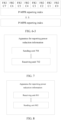
- FIG. 9 is a schematic structure diagram of a communication device 600 in accordance with an embodiment of the present application.
- the communication device may be a terminal device or a network device.
- the communication device 900 shown in FIG. 9 includes a processor 610, which may invoke and run a computer program from a memory to implement the methods in the embodiments of the present application.
- the communication device 900 may further include the memory 920.
- the processor 920 may invoke and run a computer program from the memory 920 to implement the methods in the embodiments of the present application.
- the memory 920 may be a separate device independent of the processor 910 or may be integrated in the processor 910.
- the communication device 900 may further include a transceiver 930.
- the processor 910 may control the transceiver 930 to communicate with other devices.
- the transceiver 930 may send information or data to other devices or receive information or data sent by other devices.
- the transceiver 930 may include a transmitter and a receiver.
- the transceiver 930 may further include antennas, the number of which may be one or more.
- the communication device 900 may be specifically the network device in accordance with an embodiment of the present application, and the communication device 900 may implement the corresponding processes implemented by the network device in various methods in the embodiments of the present application, which will not be described repeatedly herein for brevity.
- the communication device 900 may be specifically the mobile terminal/terminal device in accordance with an embodiment of the present application, and the communication device 900 may implement the corresponding processes implemented by the mobile terminal/terminal device in various methods in the embodiments of the present application, which will not be described repeatedly herein for brevity.
- FIG. 10 is a schematic structure diagram of a chip in accordance with an embodiment of the present application.
- the chip 1000 shown in FIG. 10 includes a processor 1010, which may invoke and run a computer program from a memory to implement the methods in the embodiments of the present application.
- the chip 1000 may further include the memory 1020.
- the processor 1010 may invoke and run the computer program from the memory 1020 to implement the methods in the embodiments of the present application.
- the memory 1020 may be a separate device independent of the processor 1010 or may be integrated in the processor 1010.
- the chip 1000 may further include an input interface 1030.
- the processor 1010 may control the input interface 1030 to communicate with other devices or chips. Specifically, the processor 1010 may acquire information or data sent by other devices or chips.
- the chip 1000 may further include an output interface 1040.
- the processor 1010 may control the output interface 1040 to communicate with other devices or chips. Specifically, the processor 1010 may output information or data to other devices or chips.
- the chip may be applied to the network device in the embodiments of the present application, and the chip may implement the corresponding processes implemented by the network device in various methods in the embodiments of the present application, which will not be described repeatedly herein for brevity.
- the chip may be applied to the mobile terminal/terminal device in the embodiments of the present application, and the chip may implement the corresponding processes implemented by the mobile terminal/terminal device in various methods in the embodiments of the present application, which will not be described repeatedly herein for brevity.
- the chip mentioned in the embodiments of the present application may be referred to as a system-level chip, a system chip, a chip system or a system-on-chip, etc.
- FIG. 11 is a schematic block diagram of a communication system 900 in accordance with an embodiment of the present application.
- the communication system 1100 may include a terminal device 1110 and a network device 1120.
- the terminal device 1110 may implement the corresponding functions implemented by the terminal device in the above-mentioned methods, and the network device 1120 may implement the corresponding functions implemented by the network device in the above-mentioned methods, which will not be described repeatedly herein for brevity.
- the processor in the embodiments of the present application may be an integrated circuit chip having a signal processing capability.
- each of the steps of the foregoing method embodiments may be implemented through an integrated logic circuit of hardware in the processor or instructions in a form of software.
- the processor described above may be a general purpose processor, a digital signal processor (DSP), an application specific integrated circuit (ASIC), a field programmable gate array (FPGA) or another programmable logic device, a discrete gate or a transistor logic device, or a discrete hardware component.
- the processor may implement or perform various methods, steps and logical block diagrams disclosed in the embodiments of the present application.
- the general purpose processor may be a microprocessor, or the processor may also be any conventional processor, or the like.
- the steps of the methods disclosed in the embodiments of the present application may be directly embodied to be implemented by a hardware decoding processor, or may be implemented by a combination of hardware and software modules in the decoding processor.
- the software modules may be located in a typical storage medium in the art, such as a random access memory, a flash memory, a read-only memory, a programmable read-only memory, an electrically erasable programmable memory, a register.
- the storage medium is located in the memory, and the processor reads information in the memory and completes the steps of the foregoing methods in combination with its hardware.
- the memory in the embodiments of the present application may be a volatile memory or a non-volatile memory, or may include both a volatile memory and a non-volatile memory.
- the non-volatile memory may be a read-only memory (ROM), a programmable read-only memory (PROM), an erasable programmable read-only memory (EPROM), an electrically erasable programmable read-only memory (EEPROM), or a flash memory.
- the volatile memory may be a random access memory (RAM), which is used as an external cache.
- RAMs may be available, such as a static random access memory (SRAM), a dynamic random access memory (DRAM), a synchronous dynamic random access memory (SDRAM), a double data rate synchronous dynamic random access memory (DDR SDRAM), an enhanced synchronous dynamic random access memory (ESDRAM), a Synchlink dynamic random access memory (SLDRAM), and a direct Rambus dynamic random access memory (DR RAM).
- SRAM static random access memory
- DRAM dynamic random access memory
- SDRAM synchronous dynamic random access memory
- DDR SDRAM double data rate synchronous dynamic random access memory
- ESDRAM enhanced synchronous dynamic random access memory
- SLDRAM Synchlink dynamic random access memory
- DR RAM direct Rambus dynamic random access memory
- the memory in the embodiments of the present application may also be a Static RAM (SRAM), a Dynamic RAM (DRAM), a Synchronous DRAM (SDRAM), a Double Data Rate SDRAM (DDR SDRAM), an Enhanced SDRAM (ESDRAM), a Synchlink DRAM (SLDRAM), a direct Rambus RAM (DR RAM), etc. That is, the memory in the embodiments of the present application is intended to include, but not be limited to, these and any other suitable types of memories.
- SRAM Static RAM
- DRAM Dynamic RAM
- SDRAM Synchronous DRAM
- DDR SDRAM Double Data Rate SDRAM
- ESDRAM Enhanced SDRAM
- SLDRAM Synchlink DRAM
- DR RAM direct Rambus RAM
- An embodiment of the present application further provides a computer readable storage medium configured to store a computer program.
- the computer readable storage medium may be applied to the network device in the embodiments of the present application, and the computer program causes the computer to perform the corresponding processes implemented by the network device in various methods in accordance with the embodiments of the present application, which will not be described repeatedly for brevity.
- the computer readable storage medium may be applied to the mobile terminal/terminal device in the embodiments of the present application, and the computer program causes the computer to perform the corresponding processes implemented by the mobile terminal/terminal device in various methods in accordance with the embodiments of the present application, which will not be described repeatedly for brevity.
- An embodiment of the present application further provides a computer program product including computer program instructions.
- the computer program product may be applied to the network device in the embodiments of the present application, and the computer program instructions cause the computer to perform the corresponding processes implemented by the network device in various methods in accordance with the embodiments of the present application, which will not be described repeatedly for brevity.
- the computer program product may be applied to the mobile terminal/terminal device in the embodiments of the present application, and the computer program instructions cause the computer to perform the corresponding processes implemented by the mobile terminal/terminal device in various methods in accordance with the embodiments of the present application, which will not be described repeatedly for brevity.
- An embodiment of the present application further provides a computer program.
- the computer program may be applied to the network device in the embodiments of the present application.
- the computer program when running on a computer, causes the computer to perform the corresponding processes implemented by the network device in various methods in accordance with the embodiments of the present application, which will not be described repeatedly for brevity.
- the computer program may be applied to the mobile terminal/terminal device in the embodiments of the present application.
- the computer program when running on a computer, causes the computer to perform the corresponding processes implemented by the mobile terminal/terminal device in various methods in accordance with the embodiments of the present application, which will not be described repeatedly for brevity.
- the disclosed systems, apparatuses and methods may be implemented in other ways.
- the apparatus embodiments described above are only illustrative, for example, the division of the units is only a logical function division, and there may be other division manners in actual implementation.
- multiple units or components may be combined or integrated into another system, or some features may be ignored or not executed.
- the shown or discussed coupling or direct coupling or communication connection between each other may be an indirect coupling or communication connection through some interfaces, apparatuses or units, or may be in electrical, mechanical or other forms.
- the unit described as a separate component may or may not be physically separated, and the component shown as a unit may or may not be a physical unit, i.e., it may be located in one place or may be distributed across multiple network units. Part or all of the units may be selected according to actual needs to achieve the purpose of the embodiments.
- various functional units in various embodiments of the present application may be integrated into one processing unit, or may exist physically separately, or two or more than two units may be integrated into one unit.
- the function if implemented in a form of software functional unit and sold or used as an independent product, may be stored in a computer readable storage medium.
- the technical solution of the present application in essence, or the part contributing to the prior art, or the part of the technical solution, may be embodied in the form of a software product, which is stored in a storage medium, and includes several instructions for causing a computer device (which may be a personal computer, a server, or a network device, etc.) to perform all or part of the steps of various embodiments of the present application.
- the aforementioned storage medium includes various media, such as a U disk, a mobile hard disk, a read-only memory (ROM), a random access memory (RAM), a magnetic disk, or an optical disk, which are capable of storing program codes.
Landscapes
- Engineering & Computer Science (AREA)
- Computer Networks & Wireless Communication (AREA)
- Signal Processing (AREA)
- Mobile Radio Communication Systems (AREA)
- Alarm Systems (AREA)
Priority Applications (1)
| Application Number | Priority Date | Filing Date | Title |
|---|---|---|---|
| EP24185587.3A EP4415433A3 (de) | 2020-03-31 | 2020-03-31 | Verfahren und vorrichtung zur meldung von leistungsreduzierungsinformationen, endgerätevorrichtung und netzwerkvorrichtung |
Applications Claiming Priority (3)
| Application Number | Priority Date | Filing Date | Title |
|---|---|---|---|
| EP24185587.3A EP4415433A3 (de) | 2020-03-31 | 2020-03-31 | Verfahren und vorrichtung zur meldung von leistungsreduzierungsinformationen, endgerätevorrichtung und netzwerkvorrichtung |
| PCT/CN2020/082316 WO2021195928A1 (zh) | 2020-03-31 | 2020-03-31 | 上报功率回退信息的方法及装置、终端设备、网络设备 |
| EP20891417.6A EP3917221B1 (de) | 2020-03-31 | 2020-03-31 | Verfahren und vorrichtung zur meldung von leistungsreduzierungsinformationen, endgerät und netzwerkgerät |
Related Parent Applications (2)
| Application Number | Title | Priority Date | Filing Date |
|---|---|---|---|
| EP20891417.6A Division-Into EP3917221B1 (de) | 2020-03-31 | 2020-03-31 | Verfahren und vorrichtung zur meldung von leistungsreduzierungsinformationen, endgerät und netzwerkgerät |
| EP20891417.6A Division EP3917221B1 (de) | 2020-03-31 | 2020-03-31 | Verfahren und vorrichtung zur meldung von leistungsreduzierungsinformationen, endgerät und netzwerkgerät |
Publications (2)
| Publication Number | Publication Date |
|---|---|
| EP4415433A2 true EP4415433A2 (de) | 2024-08-14 |
| EP4415433A3 EP4415433A3 (de) | 2024-11-06 |
Family
ID=77927735
Family Applications (2)
| Application Number | Title | Priority Date | Filing Date |
|---|---|---|---|
| EP20891417.6A Active EP3917221B1 (de) | 2020-03-31 | 2020-03-31 | Verfahren und vorrichtung zur meldung von leistungsreduzierungsinformationen, endgerät und netzwerkgerät |
| EP24185587.3A Pending EP4415433A3 (de) | 2020-03-31 | 2020-03-31 | Verfahren und vorrichtung zur meldung von leistungsreduzierungsinformationen, endgerätevorrichtung und netzwerkvorrichtung |
Family Applications Before (1)
| Application Number | Title | Priority Date | Filing Date |
|---|---|---|---|
| EP20891417.6A Active EP3917221B1 (de) | 2020-03-31 | 2020-03-31 | Verfahren und vorrichtung zur meldung von leistungsreduzierungsinformationen, endgerät und netzwerkgerät |
Country Status (6)
| Country | Link |
|---|---|
| US (2) | US11350375B2 (de) |
| EP (2) | EP3917221B1 (de) |
| JP (1) | JP7291802B2 (de) |
| KR (1) | KR20220162604A (de) |
| CN (1) | CN113748717A (de) |
| WO (1) | WO2021195928A1 (de) |
Families Citing this family (5)
| Publication number | Priority date | Publication date | Assignee | Title |
|---|---|---|---|---|
| US20240049148A1 (en) * | 2021-04-02 | 2024-02-08 | Qualcomm Incorporated | Triggering conditions for power reporting |
| KR20240122896A (ko) * | 2021-12-29 | 2024-08-13 | 베이징 시아오미 모바일 소프트웨어 컴퍼니 리미티드 | 전력 보고 방법, 장치 및 저장 매체 |
| WO2023209572A1 (en) * | 2022-04-28 | 2023-11-02 | Lenovo (Singapore) Pte Limited | Power headroom reporting |
| WO2025010563A1 (zh) * | 2023-07-07 | 2025-01-16 | 北京小米移动软件有限公司 | 通信方法、终端、网络设备 |
| US20250024383A1 (en) * | 2023-07-11 | 2025-01-16 | Qualcomm Incorporated | Frequency band power limit reporting in a user equipment |
Family Cites Families (6)
| Publication number | Priority date | Publication date | Assignee | Title |
|---|---|---|---|---|
| CN102300249B (zh) * | 2010-06-22 | 2014-10-15 | 电信科学技术研究院 | 一种上报功率裕量报告的方法、装置及系统 |
| JP5990543B2 (ja) | 2011-02-15 | 2016-09-14 | サムスン エレクトロニクス カンパニー リミテッド | 携帯端末機の使用可能送信電力報告方法および装置 |
| CN102123437B (zh) * | 2011-03-03 | 2016-02-17 | 电信科学技术研究院 | 功率余量上报和调度子帧的方法、系统及设备 |
| CN102740440B (zh) | 2011-04-02 | 2015-05-06 | 华为技术有限公司 | 控制发送功率的方法及设备 |
| US9532253B2 (en) * | 2013-09-26 | 2016-12-27 | Sharp Kabushiki Kaisha | Systems and methods for multi-connectivity operation |
| US11757483B2 (en) * | 2020-03-18 | 2023-09-12 | Comcast Cable Communications, Llc | Exposure reporting for wireless communications |
-
2020
- 2020-03-31 CN CN202080006259.0A patent/CN113748717A/zh active Pending
- 2020-03-31 WO PCT/CN2020/082316 patent/WO2021195928A1/zh not_active Ceased
- 2020-03-31 KR KR1020217040055A patent/KR20220162604A/ko not_active Withdrawn
- 2020-03-31 JP JP2021558005A patent/JP7291802B2/ja active Active
- 2020-03-31 EP EP20891417.6A patent/EP3917221B1/de active Active
- 2020-03-31 EP EP24185587.3A patent/EP4415433A3/de active Pending
-
2021
- 2021-06-28 US US17/361,276 patent/US11350375B2/en active Active
-
2022
- 2022-04-28 US US17/731,827 patent/US11665652B2/en active Active
Also Published As
| Publication number | Publication date |
|---|---|
| US11350375B2 (en) | 2022-05-31 |
| US11665652B2 (en) | 2023-05-30 |
| EP3917221B1 (de) | 2024-08-07 |
| KR20220162604A (ko) | 2022-12-08 |
| EP3917221A4 (de) | 2022-04-20 |
| EP3917221A1 (de) | 2021-12-01 |
| EP4415433A3 (de) | 2024-11-06 |
| CN113748717A (zh) | 2021-12-03 |
| US20220256481A1 (en) | 2022-08-11 |
| US20210329570A1 (en) | 2021-10-21 |
| JP7291802B2 (ja) | 2023-06-15 |
| JP2022531079A (ja) | 2022-07-06 |
| WO2021195928A1 (zh) | 2021-10-07 |
Similar Documents
| Publication | Publication Date | Title |
|---|---|---|
| US11665652B2 (en) | Method and apparatus for reporting power reduction information, terminal device and network device | |
| US12309852B2 (en) | Provide a method for random access to increase uplink capacity of a terminal device for random access | |
| CN113518416B (zh) | 上报功率回退信息的方法及装置、终端设备、网络设备 | |
| EP4156850A1 (de) | Messverfahren und -vorrichtung, endgerätevorrichtung und netzwerkvorrichtung | |
| CN114631347A (zh) | 一种小区配置方法及装置、终端设备、网络设备 | |
| CN115486146B (zh) | 上报功率回退信息的方法及装置、网络设备、终端设备 | |
| US12490237B2 (en) | Method and apparatus of information indication for paging message, terminal device and network device | |
| WO2021097698A1 (zh) | 一种上行接入方法、电子设备及存储介质 | |
| US20210250866A1 (en) | Method and apparatus for reducing terminal power consumption, and terminal | |
| CN112673661A (zh) | 一种终端能力确定方法及装置、终端 | |
| EP4156813B1 (de) | Verfahren und vorrichtung zur bwp-konfiguration, endgerätevorrichtung und netzwerkvorrichtung | |
| US12150070B2 (en) | Resource sharing method and apparatus, terminal, and network device | |
| WO2020029077A1 (zh) | 一种信息传输方法及装置、终端 | |
| CN114451004A (zh) | 一种cli测量的方法及装置、终端设备、网络设备 | |
| CN120640359A (zh) | 一种资源协调方法及装置、终端设备 | |
| WO2019210517A1 (zh) | 无线通信方法、通信设备、芯片和系统 | |
| US20220007425A1 (en) | Method and apparatus for transmitting a system information request and system | |
| EP4287755A1 (de) | Verfahren und vorrichtung zur bestimmung des verhaltens einer endgerätevorrichtung sowie endgerätevorrichtung und netzwerkvorrichtung | |
| US20210195644A1 (en) | Communication method, terminal device, and network device | |
| US20210127426A1 (en) | Method for indicating channel access type, terminal device and network device | |
| CN114846861B (zh) | 一种功率余量上报的方法装置、网络设备、终端设备 | |
| EP4106466B1 (de) | Verfahren und vorrichtung zur kanalverarbeitung | |
| CN114846860A (zh) | 一种功率余量上报的方法及装置、终端设备、网络设备 |
Legal Events
| Date | Code | Title | Description |
|---|---|---|---|
| PUAI | Public reference made under article 153(3) epc to a published international application that has entered the european phase |
Free format text: ORIGINAL CODE: 0009012 |
|
| STAA | Information on the status of an ep patent application or granted ep patent |
Free format text: STATUS: THE APPLICATION HAS BEEN PUBLISHED |
|
| AC | Divisional application: reference to earlier application |
Ref document number: 3917221 Country of ref document: EP Kind code of ref document: P |
|
| AK | Designated contracting states |
Kind code of ref document: A2 Designated state(s): AL AT BE BG CH CY CZ DE DK EE ES FI FR GB GR HR HU IE IS IT LI LT LU LV MC MK MT NL NO PL PT RO RS SE SI SK SM TR |
|
| REG | Reference to a national code |
Ref country code: DE Ref legal event code: R079 Free format text: PREVIOUS MAIN CLASS: H04W0052360000 Ipc: H04W0052020000 |
|
| PUAL | Search report despatched |
Free format text: ORIGINAL CODE: 0009013 |
|
| AK | Designated contracting states |
Kind code of ref document: A3 Designated state(s): AL AT BE BG CH CY CZ DE DK EE ES FI FR GB GR HR HU IE IS IT LI LT LU LV MC MK MT NL NO PL PT RO RS SE SI SK SM TR |
|
| RIC1 | Information provided on ipc code assigned before grant |
Ipc: H04W 52/14 20090101ALI20241002BHEP Ipc: H04W 52/36 20090101ALI20241002BHEP Ipc: H04W 52/54 20090101ALI20241002BHEP Ipc: H04W 52/02 20090101AFI20241002BHEP |
|
| STAA | Information on the status of an ep patent application or granted ep patent |
Free format text: STATUS: REQUEST FOR EXAMINATION WAS MADE |
|
| 17P | Request for examination filed |
Effective date: 20250416 |