EP4415331A1 - Routenwerbungsverfahren, -vorrichtung und -system - Google Patents
Routenwerbungsverfahren, -vorrichtung und -system Download PDFInfo
- Publication number
- EP4415331A1 EP4415331A1 EP22888850.9A EP22888850A EP4415331A1 EP 4415331 A1 EP4415331 A1 EP 4415331A1 EP 22888850 A EP22888850 A EP 22888850A EP 4415331 A1 EP4415331 A1 EP 4415331A1
- Authority
- EP
- European Patent Office
- Prior art keywords
- network device
- route
- interface
- address
- prefix
- Prior art date
- Legal status (The legal status is an assumption and is not a legal conclusion. Google has not performed a legal analysis and makes no representation as to the accuracy of the status listed.)
- Pending
Links
Images



Classifications
-
- H—ELECTRICITY
- H04—ELECTRIC COMMUNICATION TECHNIQUE
- H04L—TRANSMISSION OF DIGITAL INFORMATION, e.g. TELEGRAPHIC COMMUNICATION
- H04L12/00—Data switching networks
- H04L12/28—Data switching networks characterised by path configuration, e.g. LAN [Local Area Networks] or WAN [Wide Area Networks]
- H04L12/46—Interconnection of networks
-
- H—ELECTRICITY
- H04—ELECTRIC COMMUNICATION TECHNIQUE
- H04L—TRANSMISSION OF DIGITAL INFORMATION, e.g. TELEGRAPHIC COMMUNICATION
- H04L45/00—Routing or path finding of packets in data switching networks
- H04L45/56—Routing software
- H04L45/566—Routing instructions carried by the data packet, e.g. active networks
-
- H—ELECTRICITY
- H04—ELECTRIC COMMUNICATION TECHNIQUE
- H04L—TRANSMISSION OF DIGITAL INFORMATION, e.g. TELEGRAPHIC COMMUNICATION
- H04L12/00—Data switching networks
- H04L12/28—Data switching networks characterised by path configuration, e.g. LAN [Local Area Networks] or WAN [Wide Area Networks]
- H04L12/46—Interconnection of networks
- H04L12/4641—Virtual LANs, VLANs, e.g. virtual private networks [VPN]
-
- H—ELECTRICITY
- H04—ELECTRIC COMMUNICATION TECHNIQUE
- H04L—TRANSMISSION OF DIGITAL INFORMATION, e.g. TELEGRAPHIC COMMUNICATION
- H04L45/00—Routing or path finding of packets in data switching networks
- H04L45/02—Topology update or discovery
- H04L45/04—Interdomain routing, e.g. hierarchical routing
-
- H—ELECTRICITY
- H04—ELECTRIC COMMUNICATION TECHNIQUE
- H04L—TRANSMISSION OF DIGITAL INFORMATION, e.g. TELEGRAPHIC COMMUNICATION
- H04L45/00—Routing or path finding of packets in data switching networks
- H04L45/50—Routing or path finding of packets in data switching networks using label swapping, e.g. multi-protocol label switch [MPLS]
-
- H—ELECTRICITY
- H04—ELECTRIC COMMUNICATION TECHNIQUE
- H04L—TRANSMISSION OF DIGITAL INFORMATION, e.g. TELEGRAPHIC COMMUNICATION
- H04L45/00—Routing or path finding of packets in data switching networks
- H04L45/58—Association of routers
- H04L45/586—Association of routers of virtual routers
-
- H—ELECTRICITY
- H04—ELECTRIC COMMUNICATION TECHNIQUE
- H04L—TRANSMISSION OF DIGITAL INFORMATION, e.g. TELEGRAPHIC COMMUNICATION
- H04L45/00—Routing or path finding of packets in data switching networks
- H04L45/66—Layer 2 routing, e.g. in Ethernet based MAN's
Definitions
- This application relates to the field of communication technologies, and in particular, to a route advertisement method, an apparatus, and a system.
- An Ethernet virtual private network (Ethernet Virtual Private Network, EVPN) is a control plane protocol based on a border gateway protocol (Border Gateway Protocol, BGP).
- An internet protocol prefix advertisement (Internet Protocol Prefix Advertisement, IP Prefix for short) route is defined in a standard draft [draft-ietf-bess-evpn-prefix-advertisement-11] released by the Internet Engineering Task Force (Internet Engineering Task Force, IETF). Service interworking between subnets may be implemented by advertising the IP Prefix route.
- the draft also defines a plurality of use cases to describe an application scenario of the IP Prefix route.
- the draft defines a route advertisement rule for a plurality of single scenarios.
- internet protocol Internet Protocol
- IP Internet Protocol
- reachability information of a subnet may be advertised by advertising the IP Prefix route in an interface-less IP-VRF-to-IP-VRF model (Interface-less IP-VRF-to-IP-VRF Model, Interface-less Model for short) and an interface-ful IP-VRF-to-IP-VRF with SBD IRB model (Interface-ful IP-VRF-to-IP-VRF with SBD IRB Model, Interface-ful Model for short).
- IP Internet Protocol
- the Interface-less Model and the Interface-ful Model may be deployed in a mixed manner.
- a network virtualization edge (Network Virtualization Edge, NVE) device advertises a route based on the Interface-less Model
- a datacenter gateway (Datacenter Gateway, DGW) device that supports the Interface-ful Model cannot generate a valid routing table based on the route.
- DGW Datacenter Gateway
- a first network device advertises an EVPN internet protocol prefix IP Prefix route to a second network device, where the IP Prefix route includes a gateway internet protocol GW IP address and a multi-protocol label switching label MPLS Label, the GW IP address is an internet protocol IP address of a first interface of the first network device, and the MPLS Label is a label of a first internet protocol-virtual routing and forwarding IP-VRF instance of the first network device.
- the first network device advertises an EVPN media access control/internet protocol MAC/IP route to the second network device, where the MAC/IP route includes the IP address of the first interface and a media access control MAC address of the first interface.
- An IP Prefix route sent by the first network device in an Interface-less Model is the same as a route sent in an Interface-ful Model. This resolves a route advertisement problem in a scenario in which the Interface-less Model and the Interface-ful Model are mixed, so that service interworking can be implemented regardless of whether an RR device is deployed, service reliability in this scenario is ensured, and network planning and configuration is simplified. In addition, a maximum of one RR device is needed when the RR device is deployed. This reduces a quantity of RRs.
- this application provides a route advertisement method.
- the method includes: A first network device advertises an Ethernet virtual private network EVPN internet protocol prefix IP Prefix route to a second network device, where the IP Prefix route includes a gateway internet protocol GW IP address and a multi-protocol label switching label MPLS Label, the GW IP address is an internet protocol IP address of a first interface of the first network device, and the MPLS Label is a label of a first internet protocol-virtual routing and forwarding IP-VRF instance of the first network device.
- the first network device advertises an EVPN media access control/internet protocol MAC/IP route to the second network device, where the MAC/IP route includes the IP address of the first interface and a media access control MAC address of the first interface.
- the first network device advertises the internet protocol prefix IP Prefix route to the second network device, where the IP Prefix route includes the gateway internet protocol GW IP address and the multi-protocol label switching label MPLS Label, the GW IP address is the internet protocol IP address of the first interface of the first network device, and the MPLS Label is the label of the first internet protocol-virtual routing and forwarding IP-VRF instance of the first network device.
- the first network device advertises the EVPN media access control/internet protocol MAC/IP route to the second network device, where the MAC/IP route includes the IP address of the first interface and the media access control MAC address of the first interface.
- This resolves a route advertisement problem in the scenario in which the Interface-less Model and the Interface-ful Model are mixed, so that service interworking can be implemented regardless of whether an RR device is deployed, service reliability in this scenario is ensured, and network planning and configuration is simplified.
- a maximum of one RR device is needed when the RR device is deployed. This reduces a quantity of RRs.
- the first network device advertises the IP Prefix route and the MAC/IP route to the second network device by using a route reflector.
- the first interface of the first network device is a first supplementary broadcast domain SBD integrated routing and bridging IRB interface
- the first SBD IRB interface belongs to an SBD
- the second network device includes a second IP-VRF instance
- a second interface of the second network device is a second SBD IRB interface
- the second SBD IRB interface belongs to the SBD
- the SBD is used to connect the first IP-VRF instance and the second IP-VRF instance.
- the first interface of the first network device is a first SBD IRB interface
- the first SBD IRB interface belongs to an SBD
- the second network device includes a second IP-VRF instance
- a second interface of the second network device does not support SBD IRB.
- the first network device is a network virtualization edge NVE device or a datacenter gateway DGW device.
- the second network device is an NVE device or a DGW device.
- this application provides a route advertisement method.
- the method includes: A second network device receives an Ethernet virtual private network EVPN internet protocol prefix IP Prefix route advertised by a first network device, where the IP Prefix route includes a gateway internet protocol GW IP address and a multi-protocol label switching label MPLS Label, the GW IP address is an internet protocol IP address of a first interface of the first network device, and the MPLS Label is a label of a first internet protocol-virtual routing and forwarding IP-VRF instance of the first network device.
- the second network device receives an EVPN media access control/internet protocol MAC/IP route advertised by the first network device, where the MAC/IP route includes the IP address of the first interface and a media access control MAC address of the first interface.
- the second network device receives the IP Prefix route and the MAC/IP route by using a route reflector.
- the second network device includes a second IP-VRF instance, a second interface of the second network device does not support supplementary broadcast domain SBD integrated routing and bridging IRB, and the second network device generates, based on the IP Prefix route, a routing entry corresponding to the second IP-VRF instance, where the routing entry includes the MPLS Label.
- the second network device includes a second IP-VRF instance, a second interface of the second network device is a second SBD IRB interface, the second SBD IRB interface belongs to an SBD, the SBD is used to connect the first IP-VRF instance and the second IP-VRF instance, and the second network device generates, based on the IP Prefix route, a routing entry corresponding to the second IP-VRF instance, where the routing entry includes the GW IP address.
- the second network device generates an entry of an address resolution protocol ARP table based on the MAC/IP route, where the entry includes the IP address of the first interface and the MAC address of the first interface.
- the first network device is a network virtualization edge NVE device or a datacenter gateway DGW device.
- the second network device is an NVE device or a DGW device.
- this application provides a network device, including a transceiver unit and a processing unit.
- the transceiver unit is configured to perform a receiving operation and a sending operation in the method according to any one of the foregoing aspects and the possible implementations of any one of the foregoing aspects.
- the processing unit is configured to perform an operation other than the receiving operation and the sending operation in the method according to any one of the foregoing aspects and the possible implementations of any one of the foregoing aspects.
- the processing unit is configured to: generate the IP Prefix route, where the IP Prefix route includes the gateway internet protocol GW IP address and the multi-protocol label switching label MPLS Label; and is further configured to generate the MAC/IP route, where the MAC/IP route includes the IP address of the first interface and the media access control MAC address of the first interface.
- the transceiver unit is configured to advertise the IP Prefix route and the MAC/IP route to the second network device.
- this application provides a network device.
- the network device includes a memory and a processor.
- the memory is configured to store program code.
- the processor is configured to run instructions in the program code, to enable the network device to perform the method according to any one of the foregoing aspects and the possible implementations of any one of the foregoing aspects.
- the processor executes the instructions, to enable the network device to be configured to: advertise the IP Prefix route to the second network device, where the IP Prefix route includes the gateway internet protocol GW IP address and the multi-protocol label switching label MPLS Label; and advertise the MAC/IP route to the second network device, where the MAC/IP route includes the IP address of the first interface and the media access control MAC address of the first interface.
- this application provides a network device.
- the network device includes a communication interface and a processor.
- the communication interface is configured to perform a receiving operation and a sending operation in the method according to any one of the foregoing aspects and the possible implementations of any one of the foregoing aspects.
- the processor is configured to perform an operation other than the receiving operation and the sending operation in the method according to any one of the foregoing aspects and the possible implementations of any one of the foregoing aspects.
- the processor is configured to: generate the IP Prefix route, where the IP Prefix route includes the gateway internet protocol GW IP address and the multi-protocol label switching label MPLS Label; and is further configured to generate the MAC/IP route, where the MAC/IP route includes the IP address of the first interface and the media access control MAC address of the first interface.
- the communication interface is configured to advertise the IP Prefix route and the MAC/IP route to the second network device.
- this application provides a communication system.
- the communication system includes a first network device and a second network device.
- the first network device may be the network device according to any one of the third aspect to the fifth aspect, and is configured to perform some or all operations performed by the first network device according to any one of the foregoing aspects and the possible implementations.
- the second network device may be the network device according to any one of the third aspect to the fifth aspect, and is configured to perform some or all operations performed by the second network device according to any one of the foregoing aspects and the possible implementations.
- this application provides a computer-readable storage medium.
- the computer-readable storage medium stores instructions, and when the instructions are run on a processor, the processor is enabled to perform some or all operations in the method according to any one of the foregoing aspects and the possible implementations of any one of the foregoing aspects.
- this application provides a computer program product.
- the computer program product includes instructions.
- the processor is enabled to perform some or all operations in the method according to any one of the foregoing aspects and the possible implementations of any one of the foregoing aspects.
- the first network device sends the internet protocol prefix IP Prefix route to the second network device, where the IP Prefix route includes the gateway internet protocol GW IP address and the multi-protocol label switching label MPLS Label, the GW IP address is the internet protocol IP address of the first interface of the first network device, and the MPLS Label is the label of the first internet protocol-virtual routing and forwarding IP-VRF instance of the first network device.
- the first network device sends the media access control/internet protocol MAC/IP route to the second network device, where the MAC/IP route includes the IP address of the first interface and the media access control MAC address of the first interface.
- the IP Prefix route sent by the first network device in the Interface-less Model is the same as the IP Prefix route sent in the Interface-ful Model. This resolves the route advertisement problem in the scenario in which the Interface-less Model and the Interface-ful Model are mixed, so that service interworking can be implemented regardless of whether an RR device is deployed, service reliability in this scenario is ensured, and network planning and configuration is simplified. In addition, a maximum of one RR device is needed when the RR device is deployed. This reduces a quantity of RRs.
- IP-VRF Internet Protocol Virtual Routing and Forwarding
- An IRB interface is an integrated routing and bridging interface and is a logical interface of a bridging table (Bridging Table, BT).
- the IRB interface is associated to one IP-VRF and supports layer 2 termination and layer 3 forwarding.
- a supplementary broadcast domain is a broadcast domain (Broadcast Domain, BD) that has only the IRB interface on a network side, and is used to connect all IP-VRF instances of a same tenant.
- BD Broadcast Domain
- an NVE device has a first IP-VRF instance
- a DGW device has a second IP-VRF instance
- the first IP-VRF instance and the second IP-VRF instance belong to a same tenant
- IP-VRF instances of the same tenant are connected by using the SBD to implement interworking.
- the IRB interface of the SBD is an SBD IRB interface.
- a route target (Route Target, RT) is used to control import and export of a VPN route.
- the RT is classified into an import route target (import RT, IRT) and an export route target (export RT, ERT).
- the ERT is carried in an extended community attribute of a BGP EVPN route for transferring.
- a receiving device After receiving BGP EVPN routes, a receiving device retains only a BGP EVPN carrying an ERT that matches a local IRT. For example, an ERT carried in an EVPN route is 100:1, which matches the IRT of 100:1 of a local VPN instance on the receiving device. Then, the receiving device saves the corresponding route to a corresponding IP-VRF routing table.
- a route distinguisher (Route Distinguisher, RD) is a distinguisher of a virtual private network (Virtual Private Network, VPN) and indicates different VPNs.
- the different VPNs may have a same internet protocol version 4 (Internet Protocol version 4, IPv4) address.
- IPv4 Internet Protocol version 4, IPv4 address.
- a BGP attaches a unique distinguisher RD of a VPN to an IPv4 route prefix and converts a non-unique IPv4 address into a globally unique address.
- FIG. 1 is a schematic diagram of a scenario according to an embodiment of this application. The following describes the scenario shown in FIG. 1.
- FIG. 1 shows a scenario in which an Interface-less Model and an Interface-ful Model are mixed.
- the Interface-less Model means that a device in the scenario has no SBD IRB interface
- the Interface-ful Model means that a device in the scenario includes an SBD IRB interface.
- the scenario shown in FIG. 1 includes an NVE device, a DGW device, an RR device, and a host H1 of a wide area network (wide area network, WAN).
- FIG. 1 shows two NVE devices, which are respectively NVE1 and NVE2; three DGW devices, which are respectively DGW1, DGW2, and DGW3; one RR device; and one host H1.
- the RR separately establishes a BGP peer with the device NVE1, the device NVE2, the device DGW1, the device DGW2, and the device DGW3.
- the RR may be directly connected to the device NVE1, the device NVE2, the device DGW1, the device DGW2, and the device DGW3, or may be connected to the device NVE1, the device NVE2, the device DGW1, the device DGW2, and the device DGW3 via a network.
- a BGP peer is directly established between network devices to advertise a BGP route.
- a BGP peer is established between the device NVE1 and the device DGW1.
- a communication network between the network devices transmits data in a manner of a tunnel.
- the tunnel may be a virtual extensible local area network (Virtual Extensible Local Area Network, VXLAN) tunnel, a generic network virtualization encapsulation (Generic Network Virtualization Encapsulation, GENEVE) tunnel, or a multi-protocol label switching (Multi-protocol Label Switching, MPLS) tunnel.
- the device NVE1, the device NVE2, the device DGW2, and the device DGW3 include SBD IRB interfaces, which are respectively an interface 1, an interface 2, an interface 3, and an interface 4.
- the device DGW1 does not include an SBD IRB interface.
- a device including an SBD IRB interface supports the Interface-ful Model
- a device that does not include an SBD IRB interface supports the Interface-less Model.
- Both the NVE device and the DGW device include an IP-VRF instance.
- the device NVE1 has two BDs: a BD-1 and a BD-2.
- the BD-1 has a network device whose IP address is IP10.
- the BD-2 corresponds to a subnet (subnet) 1. Both the BD-1 and the BD-2 are associated with an IP-VRF instance.
- NVE2 has two BDs: a BD-2 and a BD-3.
- the BD-2 also corresponds to the subnet 1.
- the BD-3 corresponds to a subnet 2.
- Both the BD-2 and the BD-3 are associated with an IP-VRF instance.
- the following describes, by using an example in which a route of the subnet 1 is advertised, a route advertisement method in the scenario in which the Interface-less Model and the Interface-ful Model are mixed shown in FIG. 1 .
- the device NVE1 and the device NVE2 in FIG. 1 are both connected to the subnet 1 and may both advertise the route of the subnet 1.
- the following uses an example in which the device NVE1 advertises the route of the subnet 1 for description.
- the device NVE1 supports route advertisement in an Interface-ful Model mode, and the device NVE1 advertises an IP Prefix route and a MAC/IP route in the Interface-ful Model mode.
- the IP Prefix route is a type of an EVPN route, and the EVPN route includes an EVPN NLRI field.
- a format of the EVPN NLRI field is shown in FIG. 2 .
- the EVPN NLRI field includes, for example, a 2-byte route type (Route Type) field, a 2-byte length (Length) field, and a variable-length route type specific (Route Type Specific) field.
- Route Type indicates that the type of the EVPN route is the IP Prefix route. Therefore, the IP Prefix route is also referred to as a Type 5 route.
- Route Type Specific is NLRI of the IP Prefix route.
- the NLRI of the IP Prefix route includes an 8-byte RD field, a 10-byte Ethernet segment identifier (Ethernet Segment Identifier, ESI) field, a 4-byte Ethernet tag ID (Ethernet Tag ID) field, a 1-byte internet protocol prefix length (IP Prefix Length) field, a 4-byte internet protocol prefix (IP Prefix) field, a 4-byte gateway internet protocol address (GW IP) field, and 3-byte multi-protocol label switching label (MPLS Label) field.
- RD field a 10-byte Ethernet segment identifier
- Ethernet Tag ID 4-byte Ethernet tag ID
- IP Prefix Length 1-byte internet protocol prefix length
- IP Prefix IP Prefix
- GW IP gateway internet protocol address
- MPLS Label 3-byte multi-protocol label switching label
- That the device NVE1 needs to fill information in the NLRI of the IP Prefix route when the device NVE1 supports advertising the IP Prefix route in the Interface-ful Model mode includes: filling an RD value in the RD field shown in FIG. 3 , filling a network segment IP address of the subnet 1 in the IP Prefix field shown in FIG. 3 , and filling an IP address of an SBD IRB interface in the GW IP field shown in FIG. 3 .
- an ERT is carried in an RT extended community attribute of a BGP.
- the MAC/IP route is also a type of an EVPN route.
- the EVPN route includes an EVPN NLRI field.
- a format of the EVPN NLRI field is shown in FIG. 2 .
- Route Type indicates that the type of the EVPN route is the MAC/IP route. Therefore, the MAC/IP route is also referred to as a Type 2 route.
- Route Type Specific is NLRI of the MAC/IP route.
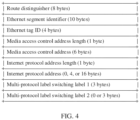
- a specific format of the NLRI of the MAC/IP route is shown in FIG. 4 .
- the MAC/IP route includes an 8-byte RD field, a 10-byte ESI field, a 4-byte Ethernet tag ID field, a 1-byte MAC address length field, a 6-byte MAC address field, a 1-byte IP address length field, a 0-byte, 4-byte, or 16-byte IP address field, a 3-byte MPLS label 1 field, and a 0-byte or 3-byte MPLS label 2 field.
- That the device NVE1 needs to fill information in the NLRI of the MAC/IP route when the device NVE1 advertises the route of the subnet 1 in the Interface-ful Model mode includes: filling the IP address of the SBD IRB interface in the IP address field shown in FIG. 4 , filling a MAC address of the SBD IRB interface in the MAC address field shown in FIG. 4 , and filling a label of the IP-VRF instance in the MPLS Label1 field shown in FIG. 4 .
- a VXLAN network identifier VXLAN Network Identifier, VNI is used as the label of the IP-VRF instance.
- an MPLS Label is used as the label of the IP-VRF instance.
- an IP address of a loopback Loopback interface of the device NVE1 is filled in a BGP next hop field, and an ERT that identifies an SBD is carried in the RT extended community attribute.
- the RR device receives the IP Prefix route, saves a corresponding route to a corresponding BGP routing table based on RD and IP Prefix in the IP Prefix NLRI, and reflects the IP Prefix route.
- the RR device receives the MAC/IP route, and reflects the MAC/IP route.
- the RR separately establishes the BGP peer with NVE1, NVE2, DGW1, DGW2, and DGW3. After receiving the IP Prefix route and the MAC/IP route that are advertised based on the BGP, the RR separately advertises the IP Prefix route to the device NVE2, the device DGW1, the device DGW2, and the device DGW3.
- the RR acts as a route reflector, and does not modify a BGP next hop, where the BGP next hop is a next hop carried when the IP Prefix route is advertised by using the BGP.
- the device DGW2 receives the MAC/IP route, where the MAC/IP route carries the IP address and the MAC address of the SBD IRB interface of NVE1; and associates the MAC/IP route to the SBD based on the ERT that identifies the SBD and that is carried in the MAC/IP route, to learn that an outbound interface is the SBD IRB interface.
- An entry of an address resolution protocol (Address Resolution Protocol, ARP) table is generated based on the MAC/IP route, and the IP address of the SBD IRB interface of NVE1, the MAC address of the SBD IRB interface of NVE1, and the outbound interface are written into the ARP table as shown in Table 1.
- Table 1 IP Prefix MAC Outbound interface IP address of the SBD IRB interface of NVE1 MAC address of the SBD IRB interface of NVE1 SBD IRB interface
- the device DGW2 finds out, based on an address in the BGP next hop, that an outbound interface of a corresponding tunnel is a tunnel Tunnel1, and records the MAC address of the SBD IRB interface of NVE1, the label of the IP-VRF instance of NVE1, and the corresponding outbound interface in a MAC table as shown in Table 2.
- Table 2 MAC MPLS Label Outbound interface MAC address of the SBD IRB interface of NVE1 Label of the IP-VRF instance of NVE1 Tunnel1
- the DGW2 receives the IP Prefix route.
- the device DGW2 supports the Interface-ful Model.
- the device DGW2 uses an address in the GW IP field as the BGP next hop, finds out, in the ARP table based on the address in the GW IP field, that a corresponding outbound interface is the SBD IRB interface, and saves the network segment IP address of the subnet 1, the IP address of the SBD IRB interface of NVE1, and the found outbound interface to a corresponding IP-VRF table as shown in Table 3, for subsequent packet forwarding.
- DGW1 receives the MAC/IP route
- the device DGW1 ignores the GW IP field, and finds out that a value filled in the MPLS Label field is 0.
- MPLS Label information in the generated IP-VRF entry is 0.
- MPLS Label is used to encapsulate a packet, and when the packet reaches the device NVE1, the packet cannot correspond to the IP-VRF instance of NVE1 based on the value of MPLS Label.
- the device NVE1 supports route advertisement in the Interface-less Model mode.
- the device NVE1 advertises reaching of the route of the subnet 1 by using the IP Prefix route.
- That the device NVE1 needs to fill information in the NLRI of the IP Prefix route when the device NVE1 advertises the route of the subnet 1 in the Interface-less Model mode includes: filling the RD value in the RD field shown in FIG. 3 , filling the network segment IP address of the subnet 1 in the IP Prefix field shown in FIG. 3 , and filling the label of the IP-VRF instance in the MPLS Label field shown in FIG. 3 .
- the IP address of the Loopback interface of the device NVE1 is filled in the BGP next hop field and the ERT is carried in the RT extended community attribute.
- the RR device receives the IP Prefix route, saves a corresponding route to a corresponding BGP routing table based on RD and IP Prefix in the IP Prefix NLRI, and reflects the IP Prefix route.
- the device DGW1 receives the IP Prefix route.
- the device DGW1 supports the Interface-less Model. After receiving the IP Prefix route, the device DGW1 ignores the GW IP field, saves information in the IP Prefix field and the MPLS Label field to a corresponding IP-VRF table, then learns, through querying based on the address in the BGP next hop, that an outbound interface of a corresponding tunnel is Tunnel1, and saves the outbound interface to an outbound interface in the corresponding IP-VRF table for subsequent packet forwarding.
- Table 4 shows the IP-VRF table generated on DGW1 based on an IP Prefix packet, where Tunnel1 indicates that the outbound interface is a tunnel.
- the device DGW1 When a subsequent packet reaches the device DGW1, the device DGW1 matches a corresponding IP Prefix based on a destination IP address of the packet. If the destination IP address of the packet belongs to the network segment IP address of the subnet 1, the device DGW1 selects this routing entry for packet forwarding.
- the device DGW2 receives the IP Prefix route.
- the device DGW2 supports the Interface-ful Model. After receiving the IP Prefix route, the device DGW2 ignores the MPLS Label field, and finds out that the IP address filled in the GW IP field is 0.
- the device DGW2 When generating an IP-VRF entry based on the IP address in the GW IP field, the device DGW2 cannot find out a corresponding outbound interface in an ARP based on the address in the GW IP field, and outbound interface information in the generated IP-VRF entry is invalid, and cannot be used for subsequent packet forwarding.
- the device DGW1 supporting the Interface-less Model mode may generate a corresponding routing entry based on the route, and GW IP information in a corresponding routing entry generated based on the route by the device DGW2 supporting the Interface-ful Model mode is invalid. If the device NVE1 advertises a route in the Interface-ful Model mode, the device DGW2 may generate a corresponding routing entry, and MPLS Label information in the routing entry generated by the device DGW1 is invalid. Therefore, in the mixed scenario, if the device NVE1 advertises a route in a single mode, service reliability cannot be ensured.
- a device NVE1 supports route advertisement in an Interface-less Model mode and an Interface-ful Model mode separately, to resolve a problem that the device NVE1 advertises a route in a single mode.
- FIG. 5 the following specifically describes a method 100 for advertising a route of a subnet 1 in a mixed deployment scenario.
- the method 100 may be applied to the scenario shown in FIG. 1 , where a network device 1 corresponds to the device NVE1 or the device NVE2 shown in FIG. 1 , a network device 2 corresponds to the device DGW1, the device DGW2, or the device DGW3 shown in FIG. 1 , and a network device 3 corresponds to the RR device shown in FIG. 1 .
- the method 100 includes S101 to S105.
- the network device 1 sends an IP Prefix route 1, where a format of the IP Prefix route 1 is shown in FIG. 3 .
- IP Prefix route 1 For information carried in the IP Prefix route 1, refer to related descriptions of the IP Prefix route sent by the device NVE1 in the Interface-less Model mode. Details are not described herein again.
- the network device 1 sends an IP Prefix route 2 and a MAC/IP route, where a format of the IP Prefix route 2 is shown in FIG. 3 , and a format of the MAC/IP route is shown in FIG. 4 .
- IP Prefix route 2 and the MAC/IP route refer to related descriptions of the route sent by the device NVE1 in the Interface-ful Model mode. Details are not described herein again.
- the network device 3 receives the IP Prefix route 1 sent by the network device 1, and reflects the IP Prefix route 1.
- the network device 3 receives the IP Prefix route 2 and the MAC/IP route that are sent by the network device 1, and reflects the MAC/IP route.
- the RR only selects one optimal route of the two routes for reflection, and the IP Prefix route 1 is reflected.
- the network device 2 receives the IP Prefix route 1 and the MAC/IP route.
- the network device 2 is the device DGW1.
- the network device 2 receives the IP Prefix route 1 refer to related descriptions in which the device NVE1 advertises a route in the Interface-less Mode and the device DGW1 receives the route in the Interface-less Mode.
- a corresponding routing entry may be generated based on the IP Prefix route 1.
- the network device 2 is the device DGW2.
- the network device 2 receives the IP Prefix route 1
- the device NVE1 advertises the route in the Interface-less Mode and the device DGW2 receives the route in the Interface-ful Mode.
- GW IP information is 0, and cannot be used for subsequent packet forwarding.
- an NVE device may advertise two types of IP Prefix routes, and a method for route advertisement in this scenario is provided.
- the NVE device may send a route according to the method 100 without a need of learning whether a DGW device supports the Interface-less Mode or the Interface-ful Mode. This simplifies network configuration.
- both the two types of routes need to be reflected to the DGW device through the same RR.
- the RR determines that the two routes correspond to a same entry in a BGP routing table.
- the RR selects one optimal route according to a BGP route selection policy, records the route in the BGP routing table, and reflects the route to a BGP peer of the RR.
- deploying two RRs in a network may be attempted.
- One RR is responsible for reflecting a route advertised by the NVE device in the Interface-less Model mode
- the other RR is responsible for reflecting a route advertised by the NVE device in the Interface-ful Model mode.
- this deployment increases deployment costs of a user.
- network management needs to plan BGP peer configuration in a one-to-one manner in advance based on a mode supported by the NVE device and the DGW device. Planning and configuration work is extremely complex and error-prone.
- embodiments of this application provide a route advertisement method.
- the method may be applied to the network shown in FIG. 1 .
- the IP Prefix route carries valid MPLS Label and valid GW IP, and then the device NVE1 sends a MAC/IP route.
- the MAC/IP route includes an IP address and a MAC address of an SBD IRB interface.
- a format of an IP Prefix route sent by the device NVE1 in an Interface-less Model is the same as that of an IP Prefix route sent by the device NVE1 in an Interface-ful Model.
- the two types of IP Prefix routes When the two types of IP Prefix routes reach a same RR device, the two types of IP Prefix routes are reflected to a BGP peer.
- the DGW device selects, based on a supported mode, a field to be parsed and generates a corresponding IP-VRF entry. For example, if the device DGW1 supports the Interface-less mode, the device DGW1 ignores a GW IP field and generates a corresponding IP-VRF entry based on an MPLS Label field for subsequent packet forwarding.
- a route advertisement problem in a scenario in which the Interface-less and the Interface-ful is mixed is resolved, so that service interworking can be implemented regardless of whether an RR device is deployed, service reliability in this scenario is ensured, and network planning and configuration is simplified.
- a maximum of one RR device is needed when the RR device is deployed. This reduces a quantity of RRs.
- the method 200 may be applied to the scenario shown in FIG. 1 .
- a network device 1 corresponds to the device NVE1 or the device NVE2 shown in FIG. 1
- a network device 2 corresponds to the device DGW1, the device DGW2, or the device DGW3 shown in FIG. 1 .
- the method 200 includes S201 to S203.
- the network device 1 sends an IP Prefix route, where the IP Prefix route includes a GW IP address and an MPLS Label, the GW IP address is an IP address of an interface of the network device 1, and the MPLS Label is a label of an IP-VRF instance of the network device 1.
- the network device 1 sends a MAC/IP route, where the MAC/IP route includes the IP address and a MAC address of the interface.
- the interface may be an SBD IRB interface of the network device, or may be a loopback Loopback interface.
- a format of the IP Prefix route is shown in FIG. 3 , and information that needs to be filled in NLRI of the IP Prefix route includes: filling an RD value in the RD field shown in FIG. 3 , filling a network segment IP address of a subnet 1 in the IP Prefix field shown in FIG. 3 , filling an IP address of the SBD IRB interface in the GW IP field shown in FIG. 3 , and filling the label of the IP-VRF instance in the MPLS Label field shown in FIG. 3 .
- an IP address of a Loopback interface of the device NVE1 is filled in a BGP next hop field, and an ERT is carried in an RT extended community attribute of a BGP.
- a format of the MAC/IP route is shown in FIG. 4 , and information that needs to be filled in NLRI of the MAC/IP route includes: filling the IP address of the SBD IRB interface in the IP field shown in FIG. 4 , filling a MAC address of the SBD IRB interface in the MAC field shown in FIG. 4 , and filling the label of the IP-VRF instance in the MPLS Label1 field shown in FIG. 4 .
- the IP address of the Loopback interface of the device NVE1 is filled in the BGP next hop field, and an ERT that identifies an SBD is carried in an RT extended community attribute.
- the IP address of the Loopback interface may be further filled in the GW IP field shown in FIG. 3 .
- Information filled in other fields is the same as that in the foregoing implementation. Details are not described herein again.
- the IP address of the loopback interface needs to be filled in the IP field shown in FIG. 4
- a MAC address of the loopback interface needs to be filled in the MAC field shown in FIG. 4 .
- the RT extended community attribute does not need to be carried.
- Information filled in other fields is the same as that in the foregoing implementation. Details are not described herein again.
- the network device 2 receives the MAC/IP route, and generates an entry of an ARP table based on the MAC/IP route, where the entry includes the IP address and the MAC address of the interface.
- the network device 2 receives the MAC/IP route, where the MAC/IP route carries the IP address and the MAC address of the SBD IRB interface of the network device 1; and associates with the SBD based on the ERT that identifies the SBD and that is carried in the route, to learn that an outbound interface is the SBD IRB interface; and writes the IP address of the SBD IRB interface of the network device 1, the MAC address of the SBD IRB interface of the network device 1, and the outbound interface into the ARP table.
- the ARP table is shown in Table 1.
- the network device 2 finds out, based on an address in a BGP next hop, that an outbound interface of a corresponding tunnel is Tunnel 1, and records the MAC address of the SBD IRB interface of the network device 1, the label of the IP-VRF instance of the network device 1, and the corresponding outbound interface in a MAC table.
- the MAC table is shown in Table 2.
- the network device 2 receives the MAC/IP route, where the MAC/IP route carries the IP address and the MAC address of the loopback interface of the network device 1, then finds out, based on the IP address of the loopback interface of the network device 1, that the outbound interface of the corresponding tunnel is Tunnel1, and writes the IP address of the loopback interface of the network device 1, the MAC address of the loopback interface of the network device 1, and the outbound interface into the ARP table.
- the ARP table is shown in Table 1.
- the MAC address of the loopback interface of the network device 1, the label of the IP-VRF instance of the network device 1, and the corresponding outbound interface are recorded in the MAC table.
- the MAC table is shown in Table 2.
- the network device 2 receives the IP Prefix route, and generates, based on the IP Prefix route, a routing entry corresponding to the IP-VRF instance.
- the network device 2 is the device DGW1, and the device DGW1 supports an Interface-less mode.
- the device DGW1 After receiving the IP Prefix route, the device DGW1 ignores the GW IP field, saves the IP Prefix field and the MPLS Label field to a corresponding IP-VRF table, then learns, through querying based on the address in the BGP next hop, that the outbound interface of the corresponding tunnel is Tunnel1, and saves the outbound interface to an outbound interface in the corresponding IP-VRF table for subsequent packet forwarding.
- the IP-VRF table is shown in Table 4.
- the network device 2 is the device DGW2, and the device DGW2 supports an Interface-ful mode.
- the device DGW2 After receiving the IP Prefix route, the device DGW2 searches the ARP table for the corresponding outbound interface based on the address in the GW IP field, and saves the IP Prefix field, the GW IP field, and a search result to a corresponding IP-VRF table.
- the IP-VRF table is shown in Table 3.
- the network device 2 is the device DGW3, and the device DGW3 supports both modes.
- the device DGW3 determines an enabled mode based on configuration. If the Interface-less mode is enabled, for a specific implementation in which the device DGW3 receives the IP Prefix route, refer to related descriptions of the first specific implementation in S203. If the Interface-ful mode is enabled, for a specific implementation in which the device DGW3 receives the IP Prefix route, refer to related descriptions of the second specific implementation in S203. Details are not described herein again.
- the method 200 includes a network device 3 that corresponds to the RR device in the scenario shown in FIG. 1 .
- the network device 3 performs S204 and S205 between S201 and S202.
- the network device 3 receives the IP Prefix route, saves the IP Prefix route to a corresponding BGP routing table, and reflects the IP Prefix route.
- the network device 3 receives the MAC/IP route, and reflects the MAC/IP route.
- the method 300 may be applied to the scenario shown in FIG. 1 , and a first network device corresponds to the NVE device in FIG. 1 .
- the method 300 may be specifically used to implement the method 200 described above.
- the first network device in the method 300 is equivalent to the network device 1 in the method 200.
- the method 300 includes S301 and S302.
- the first network device advertises an IP Prefix route to a second network device, where the IP Prefix route includes a GW IP address and an MPLS Label, the GW IP address is an IP address of a first interface of the first network device, and the MPLS Label is a label of a first IP-VRF instance of the first network device.
- the first network device advertises the IP Prefix route to the second network device via a third network device.
- a format of the IP Prefix route, and information filled in the IP Prefix route refer to related implementation in S201. Details are not described herein again.
- the first network device advertises a MAC/IP route to the second network device, where the MAC/IP route includes the IP address of the first interface and a MAC address of the first interface.
- the first network device advertises the MAC/IP route to the second network device via the third network device.
- the method 400 may be applied to the scenario shown in FIG. 1 , and a second network device corresponds to the DGW device in FIG. 1 .
- the method 400 may be specifically used to implement the method 200 described above.
- the second network device in the method 400 is equivalent to the network device 2 in the method 200.
- the method 400 includes S401 and S402.
- the second network device receives an IP Prefix route advertised by a first network device, where the IP Prefix route includes a GW IP address and an MPLS Label, the GW IP address is an IP address of a first interface of the first network device, and the MPLS Label is a label of a first IP-VRF instance of the first network device.
- the second network device receives, via a third network device, the IP Prefix route advertised by the first network device.
- the second network device receives a MAC/IP route advertised by the first network device, where the MAC/IP route includes the IP address of the first interface and a MAC address of the first interface.
- the second network device receives, via the third network device, the MAC/IP route advertised by the first network device.
- the second network device generates a routing entry based on the IP Prefix route and the MAC/IP route.
- the second network device supports an Interface-less mode.
- the second network device is equivalent to the device DGW1 in FIG. 1 , and the second network device includes a second IP-VRF instance.
- a routing entry corresponding to the second IP-VRF instance refer to related implementation in S203. Details are not described herein again.
- the second network device supports an Interface-ful mode.
- the second network device is equivalent to the device DGW2 in FIG. 1
- the second network device includes a second IP-VRF instance
- a second interface of the second network device is an SBD IRB interface
- the SBD IRB interface belongs to an SBD
- the SBD is used to connect the first IP-VRF instance and the second IP-VRF instance.
- a routing entry corresponding to the second IP-VRF instance refer to related implementation in S203. Details are not described herein again.
- the second network device supports both modes.
- the second network device is equivalent to the device DGW3 in FIG. 1 .
- the second network device determines an enabled mode based on configuration, and then performs processing of receiving a route based on the enabled mode. For details, refer to related implementation in S203. Details are not described herein again.
- FIG. 10 is a schematic structural diagram of the network device 1000 according to this embodiment of this application.
- the network device 1000 includes a transceiver unit 1001 and a processing unit 1002.
- the network device 1000 may be configured to perform the method 100, the method 200, the method 300, or the method 400 in the foregoing embodiments.
- the network device 1000 may perform the method 100 in the foregoing embodiment.
- the network device 1000 is equivalent to the network device 1 in the method 100.
- the network device 1000 may be applied to the application scenario shown in FIG. 1 , for example, may be the device NVE1 in the scenario shown in FIG. 1 .
- the transceiver unit 1001 is configured to perform receiving and sending operations performed by the network device 1 in the method 100.
- the processing unit 1002 is configured to perform an operation other than the receiving and sending operations performed by the network device 1 in the method 200.
- the transceiver unit 1001 is configured to advertise an IP Prefix route 1 to a network device 2.
- the transceiver unit 1001 is further configured to advertise a MAC/IP route to the network device 2.
- the processing unit 1002 is configured to generate the IP Prefix route and the MAC/IP route.
- the network device 1000 may perform the method 100 in the foregoing embodiment.
- the network device 1000 is equivalent to the network device 2 in the method 100.
- the network device 1000 may be applied to the application scenario shown in FIG. 1 , for example, may be the device DGW1, the device DGW2, or the device DGW3 in the scenario shown in FIG. 1 .
- the transceiver unit 1001 is configured to perform receiving and sending operations performed by the network device 2 in the method 100.
- the processing unit 1002 is configured to perform an operation other than the receiving and sending operations performed by the network device 2 in the method 100.
- the transceiver unit 1001 is configured to receive an IP Prefix route sent by a network device 1, and is further configured to receive a MAC/IP route sent by the network device 1.
- the processing unit 1002 is configured to generate, based on the IP Prefix route, a routing entry corresponding to a second IP-VRF instance.
- the processing unit 1002 is further configured to generate an entry of an ARP table based on the MAC/IP route, where the entry includes an IP address of a first interface and a MAC address of the first interface.
- the network device 1000 may perform the method 200 in the foregoing embodiment.
- the network device 1000 is equivalent to the network device 1 in the method 200.
- the network device 1000 may be applied to the application scenario shown in FIG. 1 , for example, may be the device NVE1 in the scenario shown in FIG. 1 .
- the transceiver unit 1001 is configured to perform receiving and sending operations performed by the network device 1 in the method 200.
- the processing unit 1002 is configured to perform an operation other than the receiving and sending operations performed by the network device 1 in the method 200.
- the transceiver unit 1001 is configured to advertise an IP Prefix route to a network device 2, where the IP Prefix route includes a GW IP address and an MPLS Label.
- the transceiver unit 1001 is further configured to advertise a MAC/IP route to the network device 2, where the MAC/IP route includes an IP address of a first interface and a media access control MAC address of the first interface.
- the processing unit 1002 is configured to generate the IP Prefix route and the MAC/IP route.
- the network device 1000 may perform the method 200 in the foregoing embodiment.
- the network device 1000 is equivalent to the network device 2 in the method 200.
- the network device 1000 may be applied to the application scenario shown in FIG. 1 , for example, may be the device DGW1, the device DGW2, or the device DGW3 in the scenario shown in FIG. 1 .
- the transceiver unit 1001 is configured to perform receiving and sending operations performed by the network device 2 in the method 200.
- the processing unit 1002 is configured to perform an operation other than the receiving and sending operations performed by the network device 2 in the method 200.
- the transceiver unit 1001 is configured to receive an IP Prefix route sent by a network device 1, where the IP Prefix route includes a gateway internet protocol GW IP address and a multi-protocol label switching label MPLS Label; and is further configured to receive a MAC/IP route sent by the network device 1, where the MAC/IP route includes an IP address of a first interface and a MAC address of the first interface.
- the processing unit 1002 is configured to generate, based on the IP Prefix route, a routing entry corresponding to a second IP-VRF instance.
- the processing unit 1002 is further configured to generate an entry of an ARP table based on the MAC/IP route, where the entry includes the IP address of the first interface and the MAC address of the first interface.
- the network device 1000 may perform the method 300 in the foregoing embodiment.
- the network device 1000 is equivalent to the first network device in the method 300.
- the network device 1000 may be applied to the application scenario shown in FIG. 1 , for example, may be the device NVE1 in the scenario shown in FIG. 1 .
- the transceiver unit 1001 is configured to perform receiving and sending operations performed by the first network device in the method 300.
- the processing unit 1002 is configured to perform an operation other than the receiving and sending operations performed by the first network device in the method 300.
- the transceiver unit 1001 is configured to advertise an IP Prefix route to a second network device.
- the transceiver unit 1001 is further configured to advertise a MAC/IP route to the second network device.
- the processing unit 1002 is configured to generate the IP Prefix route and the MAC/IP route.
- the network device 1000 may perform the method 400 in the foregoing embodiment.
- the network device 1000 is equivalent to the second network device in the method 400.
- the network device 1000 may be applied to the application scenario shown in FIG. 1 , for example, may be the device DGW1, the device DGW2, or the device DGW3 in the scenario shown in FIG. 1 .
- the transceiver unit 1001 is configured to perform receiving and sending operations performed by the second network device in the method 400.
- the processing unit 1002 is configured to perform an operation other than the receiving and sending operations performed by the second network device in the method 400.
- the transceiver unit 1001 is configured to receive an IP Prefix route sent by a first network device, and is further configured to receive a MAC/IP route sent by the first network device.
- the processing unit 1002 is configured to generate a corresponding entry based on the IP Prefix route and the MAC/IP route.
- division into the units is an example, and is merely a logical function division. In actual implementation, another division manner may be used.
- Functional units in this embodiment of this application may be integrated into one processing unit, or each of the units may exist alone physically, or two or more units may be integrated into one unit.
- the transceiver unit 1001 and the processing unit 1002 may be a same unit or different units.
- the integrated unit may be implemented in a form of hardware, or may be implemented in a form of a software functional unit.
- FIG. 11 is a schematic structural diagram of the network device 1100 according to this embodiment of this application.
- the network device 1100 includes a communication interface 1101 and a processor 1102 connected to the communication interface 1101.
- the communication interface is, for example, an apparatus such as a transceiver.
- the network device 1100 may be configured to perform the method 100, the method 200, the method 300, or the method 400 in the foregoing embodiments.
- the network device 1100 may be used as a network device 1 to perform an operation performed by the network device 1 in the method 100 or the method 200
- the network device 1100 may be used as a network device 2 to perform an operation performed by the network device 2 in the method 100 or the method 200.
- the communication interface 1101 is configured to perform receiving and sending operations performed by the network device 1 or the network device 2 in the method 200.
- the processor 1102 is configured to perform an operation other than the receiving and sending operations performed by the network device 1 or the network device 2 in the method 200.
- the network device 1100 may be used as a first network device to perform an operation performed by the first network device in the method 300, and the network device 1100 may be used as a second network device to perform an operation performed by the second network device in the method 400.
- the communication interface 1101 is configured to perform receiving and sending operations performed by the first network device or the second network device in the method 300 or the method 400.
- the processor 1102 is configured to perform an operation other than the receiving and sending operations performed by the first network device or the second network device in the method 300 or the method 400.
- the communication interface 1101 is configured to advertise an IP Prefix route to the network device 2, where the IP Prefix route includes a GW IP address and an MPLS Label; and is further configured to advertise a MAC/IP route to the network device 2, where the MAC/IP route includes an IP address of a first interface and a media access control MAC address of the first interface.
- the processor 1102 is configured to generate the IP Prefix route and the MAC/IP route.
- FIG. 12 is a schematic structural diagram of the network device according to this embodiment of this application.
- the network device 1200 may include a processor 1210, a memory 1220 coupled to the processor 1210, and a transceiver 1230.
- the transceiver 1230 may be, for example, a communication interface and an optical module.
- the processor 1210 may be a central processing unit (English: central processing unit, CPU for short), a network processor (English: network processor, NP for short), or a combination of the CPU and the NP.
- the processor may be an application-specific integrated circuit (English: application-specific integrated circuit, ASIC for short), a programmable logic device (English: programmable logic device, PLD for short), or a combination thereof.
- the PLD may be a complex programmable logic device (English: complex programmable logic device, CPLD for short), a field-programmable gate array (English: field-programmable gate array, FPGA for short) device, generic array logic (English: generic array logic, GAL for short), or any combination thereof.
- the processor 1210 may be one processor, or may include a plurality of processors.
- the memory 1220 may include a volatile memory (English: volatile memory), for example, a random-access memory (English: random-access memory, RAM for short).
- the memory may include a non-volatile memory (English: non-volatile memory), for example, a read-only memory (English: read-only memory, ROM for short), a flash memory (English: flash memory), a hard disk drive (English: hard disk drive, HDD for short), or a solid-state drive (English: solid-state drive, SSD for short).
- the memory 1220 may further include a combination of the foregoing memories.
- the memory 1220 may be one memory, or may include a plurality of memories.
- the memory 1220 stores computer-readable instructions, and the computer-readable instructions include a plurality of software modules, for example, a sending module 1221, a processing module 1222, and a receiving module 1223.
- the processor 1210 may perform a corresponding operation based on an indication of each software module. In this embodiment, an operation performed by one software module is actually an operation performed by the processor 1210 based on an indication of the software module.
- the processor 1210 may alternatively store program code or instructions for executing the solution of this application. In this case, the processor 1201 does not need to read the program code or the instructions from the memory 1220.
- the network device 1200 may be configured to perform the method 100, the method 200, the method 300, or the method 400 in the foregoing embodiments. Specifically, the network device 1200 may be used as a network device 1 to perform an operation performed by the network device 1 in the method 100 or the method 200, and the network device 1200 may be used as a network device 2 to perform an operation performed by the network device 2 in the method 100 or the method 200. The network device 1200 may be used as a first network device to perform an operation performed by the first network device in the method 300, and the network device 1200 may be used as a second network device to perform an operation performed by the second network device in the method 400.
- the processor 1210 is configured to execute related instructions in the memory 1220, to enable the communication apparatus 1200 to be configured to: advertise an IP Prefix route to a network device 2, where the IP Prefix route includes a GW IP address and an MPLS Label; and advertise a MAC/IP route to the network device 2, where the MAC/IP route includes an IP address of a first interface and a media access control MAC address of the first interface.
- An embodiment of this application further provides a computer-readable storage medium.
- the computer-readable storage medium stores instructions.
- the processor is enabled to perform any one or more operations in the method (for example, the method 100, the method 200, the method 300, or the method 400) in any one of the foregoing embodiments.
- An embodiment of this application further provides a computer program product, including a computer program.
- the processor is enabled to perform any one or more operations in the method (for example, the method 100, the method 200, the method 300, or the method 400) in any one of the foregoing embodiments.
- An embodiment of this application further provides a communication system, including a first network device and a second network device.
- a structure of the first network device and a structure of the second network device are shown as any one of the network devices corresponding to FIG. 10 to FIG. 12 .
- the communication system is configured to implement some or all of operations in any one of the method 100, the method 200, the method 300, and the method 400 in embodiments corresponding to FIG. 6 to FIG. 9 .
- An embodiment of this application further provides another communication system, including at least one memory and at least one processor.
- the at least one memory stores instructions, and the at least one processor executes the instructions, to enable the communication system to implement some or all of the operations in any one of the method 100, the method 200, the method 300, and the method 400 in any one of the foregoing embodiments of this application.
- An embodiment of this application further provides a chip system, including a processor, where the processor is coupled to a memory.
- the memory is configured to store a program or instructions, and when the program or the instructions is/are executed by the processor, the chip system is enabled to implement some or all of the operations in any one of the method 100, the method 200, the method 300, and the method 400 in any one of the foregoing embodiments of this application.
- processors in the chip system there may be one or more processors in the chip system.
- the processor may be implemented by using hardware, or may be implemented by using software.
- the processor When the processor is implemented by using the hardware, the processor may be a logic circuit, an integrated circuit, or the like.
- the processor When the processor is implemented by using the software, the processor may be a general-purpose processor, and is implemented by reading software code stored in the memory.
- the memory may be integrated with the processor, or may be disposed separately from the processor.
- the memory may be a non-transitory processor, for example, a read-only memory ROM.
- the memory and the processor may be integrated into a same chip, or may be separately disposed on different chips.
- a type of the memory and a manner of disposing the memory and the processor are not specifically limited in this application.
- the chip system may be an FPGA, an ASIC, a system on chip (system on chip, SoC), a CPU, an NP, a digital signal processing circuit (digital signal processor, DSP), a microcontroller unit (microcontroller unit, MCU), a programmable controller (programmable logic device, PLD), or another integrated chip.
- SoC system on chip
- DSP digital signal processor
- MCU microcontroller unit
- PLD programmable controller
- the disclosed system, apparatus, and method may be implemented in another manner.
- the foregoing described apparatus embodiments are merely examples.
- division into units is merely logical service division and there may be another division manner during actual implementation.
- a plurality of units or components may be combined or integrated into another system, or some features may be ignored or not performed.
- the displayed or discussed mutual couplings or direct couplings or communication connections may be implemented through some interfaces.
- the indirect couplings or communication connections between the apparatuses or units may be implemented in an electronic form, a mechanical form, or another form.
- the units described as separate parts may or may not be physically separate, and parts displayed as units may or may not be physical units, in other words, may be located in one position, or may be distributed on a plurality of network units. Some or all of the units may be selected based on an actual requirement to achieve the objective of the solution of embodiments.
- service units in embodiments of this application may be integrated into one processing unit, or each of the units may exist alone physically, or two or more units may be integrated into one unit.
- the integrated unit may be implemented in a form of hardware, or may be implemented in a form of a software service unit.
- the integrated unit When the integrated unit is implemented in the form of the software service unit and sold or used as an independent product, the integrated unit may be stored in a computer-readable storage medium.
- the computer software product is stored in a storage medium and includes several instructions for instructing one computer device (which may be a personal computer, a server, a network device, or the like) to perform all or some of the steps of the methods in embodiments of this application.
- the storage medium includes any medium that can store program code, such as a USB flash drive, a removable hard disk, a read-only memory (ROM, Read-Only Memory), a random access memory (RAM, Random Access Memory), a magnetic disk, or an optical disc.
- services described in the present invention may be implemented by using hardware, software, firmware, or any combination thereof.
- the services may be stored in a computer-readable medium or transmitted as one or more instructions or code in the computer-readable medium.
- the computer-readable medium includes a computer storage medium and a communication medium, where the communication medium includes any medium that enables a computer program to be transmitted from one place to another.
- the storage medium may be any available medium accessible by a general-purpose or dedicated computer.
Landscapes
- Engineering & Computer Science (AREA)
- Computer Networks & Wireless Communication (AREA)
- Signal Processing (AREA)
- Computer Security & Cryptography (AREA)
- Data Exchanges In Wide-Area Networks (AREA)
Applications Claiming Priority (2)
| Application Number | Priority Date | Filing Date | Title |
|---|---|---|---|
| CN202111301919.0A CN116074245A (zh) | 2021-11-04 | 2021-11-04 | 一种路由发布的方法、装置及系统 |
| PCT/CN2022/099511 WO2023077814A1 (zh) | 2021-11-04 | 2022-06-17 | 一种路由发布的方法、装置及系统 |
Publications (2)
| Publication Number | Publication Date |
|---|---|
| EP4415331A1 true EP4415331A1 (de) | 2024-08-14 |
| EP4415331A4 EP4415331A4 (de) | 2025-01-29 |
Family
ID=86180859
Family Applications (1)
| Application Number | Title | Priority Date | Filing Date |
|---|---|---|---|
| EP22888850.9A Pending EP4415331A4 (de) | 2021-11-04 | 2022-06-17 | Routenwerbungsverfahren, -vorrichtung und -system |
Country Status (4)
| Country | Link |
|---|---|
| US (1) | US12621239B2 (de) |
| EP (1) | EP4415331A4 (de) |
| CN (1) | CN116074245A (de) |
| WO (1) | WO2023077814A1 (de) |
Families Citing this family (3)
| Publication number | Priority date | Publication date | Assignee | Title |
|---|---|---|---|---|
| CN116074245A (zh) * | 2021-11-04 | 2023-05-05 | 华为技术有限公司 | 一种路由发布的方法、装置及系统 |
| CN116471220A (zh) * | 2022-01-11 | 2023-07-21 | 华为技术有限公司 | 一种信息上报方法、信息处理方法及装置 |
| US20260089138A1 (en) * | 2024-09-25 | 2026-03-26 | Cisco Technology, Inc. | Dynamic bringup of secure tunneling of access-controlled network domain interconnect traffic |
Family Cites Families (10)
| Publication number | Priority date | Publication date | Assignee | Title |
|---|---|---|---|---|
| US9985867B2 (en) * | 2015-12-11 | 2018-05-29 | Cisco Technology, Inc. | Optimizing EVPN for data centers with redundant top-of-rack deployments |
| US10958570B2 (en) * | 2019-04-04 | 2021-03-23 | Cisco Technology, Inc. | Interoperability between symmetric and asymmetric EVPN IRB modes |
| CN110505152B (zh) * | 2019-09-11 | 2022-02-22 | 迈普通信技术股份有限公司 | 路由过滤方法、装置及电子设备 |
| US11063860B2 (en) * | 2019-09-20 | 2021-07-13 | Juniper Networks, Inc. | Control plane-based EVPN optimized inter-subnet multicast (OISM) forwarding |
| CN111083034B (zh) * | 2019-12-24 | 2022-03-01 | 浪潮思科网络科技有限公司 | 一种在evpn下管理vxlan隧道的方法及设备、介质 |
| US11804983B2 (en) * | 2021-01-15 | 2023-10-31 | Hewlett Packard Enterprise Development Lp | Method and system to scale routing in Ethernet Virtual Private Network Symmetric Integrated Routing and Bridging deployments |
| CN115701052A (zh) * | 2021-07-14 | 2023-02-07 | 中兴通讯股份有限公司 | 转发表的查找方法及装置、存储介质及电子装置 |
| CN116074245A (zh) * | 2021-11-04 | 2023-05-05 | 华为技术有限公司 | 一种路由发布的方法、装置及系统 |
| US12375401B2 (en) * | 2022-08-11 | 2025-07-29 | Arista Networks, Inc. | Overlay route optimization across data centers |
| US12452159B2 (en) * | 2023-09-01 | 2025-10-21 | Ciena Corporation | Advertisement of selective EVPN routes based on route types |
-
2021
- 2021-11-04 CN CN202111301919.0A patent/CN116074245A/zh active Pending
-
2022
- 2022-06-17 WO PCT/CN2022/099511 patent/WO2023077814A1/zh not_active Ceased
- 2022-06-17 EP EP22888850.9A patent/EP4415331A4/de active Pending
-
2024
- 2024-04-30 US US18/650,883 patent/US12621239B2/en active Active
Also Published As
| Publication number | Publication date |
|---|---|
| EP4415331A4 (de) | 2025-01-29 |
| CN116074245A (zh) | 2023-05-05 |
| US20240283737A1 (en) | 2024-08-22 |
| US12621239B2 (en) | 2026-05-05 |
| WO2023077814A1 (zh) | 2023-05-11 |
Similar Documents
| Publication | Publication Date | Title |
|---|---|---|
| US11736398B2 (en) | Stateless protocol translation | |
| US12621239B2 (en) | Route advertisement method, apparatus, and system | |
| US11082341B2 (en) | Data processing | |
| US9448821B2 (en) | Method and system for realizing virtual machine mobility | |
| US11895006B2 (en) | Communication method, device, and system | |
| US20190014040A1 (en) | Edge network node and method for configuring a service therein | |
| CN106713103B (zh) | 用于虚拟和物理网络集成的方法和系统 | |
| CN108199963B (zh) | 报文转发方法和装置 | |
| US12224930B2 (en) | Establishment of method and apparatus for implementing entry backup | |
| CN106559511A (zh) | 云系统、云端公共服务系统及用于云系统的互访方法 | |
| CN111404797B (zh) | 控制方法、sdn控制器、sdn接入点、sdn网关及ce | |
| CN102959906B (zh) | 多归属站点内主机的路由选择方法和装置 | |
| US11936614B2 (en) | Method and apparatus for sending reply packet, computing device, and storage medium | |
| EP4398543A1 (de) | Routenverteilungsverfahren, paketweiterleitungsverfahren, vorrichtung und system | |
| CN101741926B (zh) | 站点内自动隧道寻址协议实现方法及装置 | |
| CN107547686B (zh) | Arp请求报文处理方法和装置 | |
| US20240388532A1 (en) | Route advertisement method, network device, and system |
Legal Events
| Date | Code | Title | Description |
|---|---|---|---|
| STAA | Information on the status of an ep patent application or granted ep patent |
Free format text: STATUS: THE INTERNATIONAL PUBLICATION HAS BEEN MADE |
|
| PUAI | Public reference made under article 153(3) epc to a published international application that has entered the european phase |
Free format text: ORIGINAL CODE: 0009012 |
|
| STAA | Information on the status of an ep patent application or granted ep patent |
Free format text: STATUS: REQUEST FOR EXAMINATION WAS MADE |
|
| 17P | Request for examination filed |
Effective date: 20240507 |
|
| AK | Designated contracting states |
Kind code of ref document: A1 Designated state(s): AL AT BE BG CH CY CZ DE DK EE ES FI FR GB GR HR HU IE IS IT LI LT LU LV MC MK MT NL NO PL PT RO RS SE SI SK SM TR |
|
| A4 | Supplementary search report drawn up and despatched |
Effective date: 20250108 |
|
| RIC1 | Information provided on ipc code assigned before grant |
Ipc: H04L 45/00 20220101ALI20241223BHEP Ipc: H04L 45/586 20220101ALI20241223BHEP Ipc: H04L 12/46 20060101ALI20241223BHEP Ipc: H04L 45/50 20220101AFI20241223BHEP |
|
| DAV | Request for validation of the european patent (deleted) | ||
| DAX | Request for extension of the european patent (deleted) |