EP4415296A1 - Vorrichtung und verfahren zur sondierung in einem netzwerk mit mehreren zugangspunkten - Google Patents
Vorrichtung und verfahren zur sondierung in einem netzwerk mit mehreren zugangspunkten Download PDFInfo
- Publication number
- EP4415296A1 EP4415296A1 EP24155605.9A EP24155605A EP4415296A1 EP 4415296 A1 EP4415296 A1 EP 4415296A1 EP 24155605 A EP24155605 A EP 24155605A EP 4415296 A1 EP4415296 A1 EP 4415296A1
- Authority
- EP
- European Patent Office
- Prior art keywords
- access point
- map
- data packet
- null data
- sounding
- Prior art date
- Legal status (The legal status is an assumption and is not a legal conclusion. Google has not performed a legal analysis and makes no representation as to the accuracy of the status listed.)
- Pending
Links
Images


Classifications
-
- H—ELECTRICITY
- H04—ELECTRIC COMMUNICATION TECHNIQUE
- H04L—TRANSMISSION OF DIGITAL INFORMATION, e.g. TELEGRAPHIC COMMUNICATION
- H04L5/00—Arrangements affording multiple use of the transmission path
- H04L5/003—Arrangements for allocating sub-channels of the transmission path
- H04L5/0032—Distributed allocation, i.e. involving a plurality of allocating devices, each making partial allocation
- H04L5/0035—Resource allocation in a cooperative multipoint environment
-
- H—ELECTRICITY
- H04—ELECTRIC COMMUNICATION TECHNIQUE
- H04L—TRANSMISSION OF DIGITAL INFORMATION, e.g. TELEGRAPHIC COMMUNICATION
- H04L5/00—Arrangements affording multiple use of the transmission path
- H04L5/003—Arrangements for allocating sub-channels of the transmission path
- H04L5/0044—Allocation of payload; Allocation of data channels, e.g. PDSCH or PUSCH
-
- H—ELECTRICITY
- H04—ELECTRIC COMMUNICATION TECHNIQUE
- H04L—TRANSMISSION OF DIGITAL INFORMATION, e.g. TELEGRAPHIC COMMUNICATION
- H04L5/00—Arrangements affording multiple use of the transmission path
- H04L5/003—Arrangements for allocating sub-channels of the transmission path
- H04L5/0048—Allocation of pilot signals, i.e. of signals known to the receiver
-
- H—ELECTRICITY
- H04—ELECTRIC COMMUNICATION TECHNIQUE
- H04L—TRANSMISSION OF DIGITAL INFORMATION, e.g. TELEGRAPHIC COMMUNICATION
- H04L5/00—Arrangements affording multiple use of the transmission path
- H04L5/003—Arrangements for allocating sub-channels of the transmission path
- H04L5/0053—Allocation of signalling, i.e. of overhead other than pilot signals
-
- H—ELECTRICITY
- H04—ELECTRIC COMMUNICATION TECHNIQUE
- H04L—TRANSMISSION OF DIGITAL INFORMATION, e.g. TELEGRAPHIC COMMUNICATION
- H04L5/00—Arrangements affording multiple use of the transmission path
- H04L5/0091—Signalling for the administration of the divided path, e.g. signalling of configuration information
- H04L5/0094—Indication of how sub-channels of the path are allocated
-
- H—ELECTRICITY
- H04—ELECTRIC COMMUNICATION TECHNIQUE
- H04W—WIRELESS COMMUNICATION NETWORKS
- H04W84/00—Network topologies
- H04W84/02—Hierarchically pre-organised networks, e.g. paging networks, cellular networks, WLAN [Wireless Local Area Network] or WLL [Wireless Local Loop]
- H04W84/10—Small scale networks; Flat hierarchical networks
- H04W84/12—WLAN [Wireless Local Area Networks]
Definitions
- aspects of the inventive concept relate to wireless communication, and more particularly, to sounding for channel estimation in a multiple access point (MAP) network of a wireless local area network (WLAN) system.
- MAP multiple access point
- WLAN wireless local area network
- a WLAN is a technology for interconnecting two or more devices using a wireless signal transmission scheme.
- the WLAN may be based on the Institute of Electrical and Electronics Engineers (IEEE) 802.11 standard.
- IEEE Institute of Electrical and Electronics Engineers
- the 802.11 standard has been developed according to standards like 802.11b, 802.1 1a, 802.11g, 802.11n, 802.11ac, and 802.11ax and may support transmission speeds up to 1 Gbyte/s based on the orthogonal frequency-division multiplexing (OFDM) technique.
- OFDM orthogonal frequency-division multiplexing
- a MAP network A technology related to a multiple AP network (hereinafter, referred to as a MAP network) is being proposed to reduce interference between APs.
- aspects of the inventive concept provide an apparatus and method for efficiently performing sounding for channel estimation in a multiple access point (MAP) network of a wireless local area network (WLAN) system.
- MAP multiple access point
- WLAN wireless local area network
- a method of operating a first apparatus in a wireless local area network (WLAN) system including receiving a multiple access point (MAP) network frame from a second apparatus, identifying a null data packet (NDP) transmission method for MAP sounding from the MAP network frame, and transmitting a first NDP to a third apparatus in association with transmission of a second NDP from the second apparatus to the third apparatus within an NDP transmission period based on an identified NDP transmission scheme.
- MAP multiple access point
- NDP null data packet
- the first apparatus and the second apparatus are access points (APs).
- the third apparatus may be a station (e.g. a user equipment).
- Each null data packet may comprise a preamble portion, but not include a payload.
- the MAP sounding may comprise performing sounding for channel estimation (i.e. performing channel sounding).
- the transmitting the first NDP to the third apparatus in association with transmission of the second NDP comprises transmitting the first NDP and the second NDP based on the NDP transmission scheme in response to the identification of the NDP transmission scheme.
- the null data packet transmission period is a transmission period, the length of which is dependent upon the identified NDP transmission scheme.
- identifying the null data packet transmission scheme comprises: checking a second value indicating the NDP transmission scheme from a NDP type subfield of a common information field of the MAP network frame, in response to a first value of a MAP mode field of the MAP network frame indicating a MAP sounding mode.
- the common information field may comprise information that is common to the first apparatus and the second apparatus.
- the identifying of the access point information field assigned to the first apparatus comprises comparing a first value of a basic service sets ID subfield of the access point information field with a second value that is a basic service sets ID assigned to the first apparatus.
- the access point information field assigned to the first apparatus may be identified in response to determining that the first value and the second value match.
- the method further comprises: following transmission of the first NDP, transmitting a first multiple access point trigger frame to the third apparatus; and following, the transmission of the first multiple access point trigger frame, receiving a multiple access point sounding feedback associated with the first multiple access point trigger frame from the third apparatus.
- the method comprises the second apparatus transmitting the second NDP. In some embodiments, the method comprises: following the transmission of the first NDP, receiving sounding feedback from the third apparatus.
- a method of operating a first apparatus in a wireless local area network (WLAN) system including determining second apparatuses participating in MAP sounding as access points (APs) and third apparatuses participating in the MAP sounding as stations (STAs), determining a null data packet (NDP) transmission scheme for the MAP sounding, generating a multiple access point (MAP) network frame indicating the second apparatuses, the third apparatuses, and the NDP transmission scheme, and transmitting the MAP network frame to the second apparatuses and the third apparatuses.
- WLAN wireless local area network
- the multiple access point network frame may identify each of the second apparatuses.
- the method may comprises: determining based on the multiple access point network frame, a common format of null data packets of the second apparatuses; and determining, based on the multiple access point network frame, individual settings for null data packet generation of each of the second apparatuses.
- the multiple access point network may comprises fourth apparatuses, which are access points, the fourth apparatuses including the first apparatus and the second apparatuses.
- the method may further comprises transmitting a null data packet to one of the third apparatuses in association with transmission of a further null data packet from one of the second apparatuses to the one of the third apparatuses within an null data packet transmission period based on the determined null data packet (NDP) transmission scheme.
- NDP null data packet
- a method of operating a first apparatus in a wireless local area network (WLAN) system including receiving a multiple access point (MAP) network frame from a second apparatus, obtaining information regarding MAP sounding from the MAP network frame, receiving null data packets (NDPs) from the second apparatus and a third apparatus based on the information regarding the MAP sounding, estimating channels between the first apparatus and each of the second apparatus and the third apparatus based on the NDPs, and transmitting MAP sounding feedbacks indicating estimated channels to the second apparatus and the third apparatus.
- MAP multiple access point
- NDPs null data packets
- FIG. 1 is a diagram showing a wireless communication system 10 according to an embodiment.
- FIG. 1 shows a wireless local area network (WLAN) system as an example of the wireless communication system 10.
- WLAN wireless local area network
- aspects of the inventive concept may also be applied to any communication system having a similar technical background and a similar channel structure (e.g., a cellular communication system like long term evolution (LTE), LTE-advanced (LTE-A), new radio (NR), wireless broadband (WiBro), and global system for mobile communication or a short-range communication system like Bluetooth (Bluetooth) or near field communication (NFC)) with slight modifications within the scope of the inventive concept, based on a judgment of one of ordinary skill in the art.
- LTE long term evolution
- LTE-A LTE-advanced
- NR new radio
- WiBro wireless broadband
- Bluetooth Bluetooth
- NFC near field communication
- various functions described below may be implemented or supported by artificial intelligence technology or one or more computer programs, each of which is composed of computer readable program codes and implemented on a computer readable medium.
- application and “program” refer to one or more computer programs, software components, instruction sets, procedures, functions, objects, classes, instances, related data, or portions thereof suitable for the implementation of suitable computer readable program codes.
- computer readable program codes includes all types of computer codes including source codes, object codes, and executable codes.
- computer readable medium includes all types of media that may be accessed by computers, such as a read only memory (ROM), a random access memory (RAM), a hard disk drive, a compact disk (CD), a digital video disk (DVD), or other types of memories.
- a "non-transitory" computer readable medium excludes wired, wireless, optical, or other types of communication links that transmit transitory electrical or other signals.
- the non-transitory computer readable medium includes a medium in which data may be permanently stored and a medium in which data may be stored and later overwritten, such as a rewritable optical disk or an erasable memory device.
- the wireless communication system 10 may include a first access point AP1, a second access point AP2, a first station STA1, a second station STA2, a third station STA3, and a fourth station STA4.
- the first access point AP1 and the second access point AP2 may access a network including the Internet, an Internet protocol (IP) network, or any other network.
- IP Internet protocol
- the first access point AP1 may provide access to the network to the first station STA1 and the second station STA2 within a first basic service set (BSS) 11, and the second access point AP2 may provide access to the network to the third station STA3 and the fourth station STA4 within a second BSS 12.
- BSS basic service set
- a BSS may be understood as a coverage region in which an access point may control access to a network.
- the first access point AP 1 and the second access point AP2 may communicate with at least one of the first station STA1, the second station STA2, the first access point AP1 and the third station STA3, and the fourth station STA4 based on the wireless fidelity (WiFi) or any other WLAN access technology.
- WiFi wireless fidelity
- An access point may be referred to as a router and a gateway.
- a station may be referred to as a mobile station, a subscriber station, a terminal, a mobile terminal, a wireless terminal, a user equipment, and/or a user apparatus.
- a station may be a portable device like a mobile phone, a laptop computer, or a wearable device or may be a stationary device like a desktop computer or a smart TV.
- an access point may be interchangeably referred to as an AP, and a station may be interchangeably referred to as an STA.
- the first access point AP1 and the second access point AP2 may allocate at least one resource unit (RU) to at least one of first to fourth stations STA1 to STA4.
- the first access point AP1 and the second access point AP2 may transmit data through at least one allocated RU, and the at least one station may receive data through the at least one allocated RU.
- the first access point AP1 and the second access point AP2 may allocate only a single RU to at least one station.
- the first access point AP1 and the second access point AP2 may allocate a multi-resource unit (MRU) including two or more RUs to at least one station (i.e. to each station).
- MRU multi-resource unit
- the first access point AP1 may allocate an MRU to at least one of first station STA1 and the second station STA2 and transmit data through the allocated MRU.
- the first access point AP1 and the second access point AP2 and the first to fourth stations STA1 to STA4 may communicate with each other by using a beamforming technique.
- the first access point AP1 may perform single-user beamforming with the first station STA1 to improve reception performance in communication with the first station STA1 or improve reception performance in overall communication with the first station STA1 and the second station STA2 by removing interference between the first station STA1 and the second station STA2 by performing multi-user beamforming with the first station STA1 and the second station STA2.
- a MAP network In an environment of a multiple AP network (hereinafter referred to as a MAP network) including the first access point AP1 and the second access point AP2, communication between the first access point AP1 and the first station STA1 and the second station STA2 with the first BSS 11 and communication between the second access point AP2 and the third station STA3 and the fourth station STA4 with the second BSS 12 may interfere with each other.
- the first access point AP1 and the second access point AP2 may select and perform any one of a coordinated beamforming operation and a joint transmission operation. Details of the coordinated beamforming operation and the joint transmission operation are described below with reference to FIGS. 5A and 5B .
- the first access point AP1 and the second access point AP2 may need channel state information regarding stations in different BSSs to perform a coordinated beamforming operation or a joint transmission operation.
- the first access point AP1 may need not only channel state information with respect to the first station STA1 and the second station STA2 in the first BSS 11, but may also need channel state information with respect to the third station STA3 and the fourth station STA4 in the second BSS 12.
- the second access point AP2 may need not only channel state information with respect to the third station STA3 and the fourth station STA4 in the second BSS 12, but may also need channel state information with respect to the first station STA1 and the second station STA2 in the first BSS 11.
- the first access point AP1 and the second access point AP2 may obtain channel state information regarding the first to fourth stations STA1 to STA4 in the first BSS 11 and the second BSS 12 to perform a MAP interference enhancing operation for reducing mutual interference between the first access point AP1 and the second access point AP2.
- the MAP interference enhancing operation is an operation capable of reducing mutual interference between access points in a MAP network environment and may be defined as an operation that additionally needs channel state information regarding stations in other BSSs.
- MAP sounding for efficiently and effectively obtaining channel state information from the first to fourth stations STA1 to STA4 in the first BSS 11 and the second BSS 12 may be performed.
- MAP sounding may include a plurality of operations for access points participating in the MAP sounding to collect channel state information from stations participating in the MAP sounding.
- the first access point AP1 and the second access point AP2 may perform MAP sounding signaling.
- the MAP sounding signaling between the first access point AP1 and the second access point AP2 may include signaling for determining a subject for controlling MAP sounding and transmission/reception of a MAP network frame in the MAP sounding.
- FIG. 1 it is described on the premise that the first access point AP1 and the second access point AP2 and the first to fourth stations STA1 to STA4 participate in the MAP sounding.
- the number of access points and stations participating in MAP sounding may be adaptively changed.
- the first access point AP1 and the second access point AP2 may perform MAP sounding signaling within the first BSS 11 and the second BSS 12 controlled by the first access point AP1 and the second access point AP2, respectively.
- MAP sounding signaling in the first BSS 11 may include transmission/reception operations regarding a null data packet (NDP) and transmission/reception operations regarding a MAP sounding feedback including channel state information between the first access point AP1 and the first station STA1 and the second station STA2.
- NDP null data packet
- MAP sounding signaling in the second BSS 12 may include transmission/reception operations regarding an NDP packet and transmission/reception operations regarding a MAP sounding feedback including channel state information between the second access point AP2 and the third station STA3 and the fourth station STA4.
- the first access point AP1 and the second access point AP2 may each perform MAP sounding signaling with a different first BSS 11 or a different second BSS 12.
- MAP sounding signaling in the different second BSS 12 may include transmission/reception operations regarding a NDP and transmission/reception operations regarding a MAP sounding feedback including channel state information between the first access point AP1 and the third station STA3 and the fourth station STA4.
- MAP sounding signaling in the different first BSS 11 may include transmission/reception operations regarding a NDP and transmission/reception operations regarding a MAP sounding feedback including channel state information between the second access point AP2 and the first station STA1 and the second station STA2.
- the first access point AP1 is a subject for controlling MAP sounding.
- an access point that is the subject of controlling MAP sounding may be referred to as a sharing access point (or sharing AP), and the rest of access points of the MAP sounding may be referred to as shared access points (or shared APs).
- the first access point AP1 and the second access point AP2 may exchange MAP network-related information including information regarding corresponding BSSs (i.e., the first BSS 11 and the second BSS 12) and determine the first access point AP1 as the subject of controlling MAP sounding.
- information regarding the first BSS 11 and the second BSS 12 may include information regarding stations belonging to the corresponding BSSs.
- first access point AP1 which is a sharing access point.
- the first access point AP1 may determine shared access points participating in MAP sounding and stations participating in MAP sounding. Although only the first access point AP1 and the second access point AP2 are shown in FIG. 1 , it is merely an embodiment, and a MAP network may include more access points. In this case, the first access point AP1 may determine shared access points participating in MAP sounding from among a plurality of access points. For example, the first access point AP1 may determine that the second access point AP2 and the first to fourth stations STA1 to STA4 are participating in MAP sounding.
- the first access point AP1 may determine an NDP transmission scheme for MAP sounding.
- the NDP transmission scheme may be commonly applied when access points participating in MAP sounding transmit NDPs to stations participating in the MAP sounding.
- the NDP transmission scheme may include a first scheme in which access points sequentially transmit NDPs to stations in a certain order within an NDP transmission period (hereinafter also referred to as a 'serial NDP transmission' scheme) and a second scheme in which access points simultaneously transmit NDPs to stations within an NDP transmission period (hereinafter also referred to as a 'joint NDP transmission' scheme).
- any one of a scheme in which NDPs transmitted from access points are coordinated by the access points to be orthogonal to each other (hereinafter also referred to as a 'joint NDP-11be-like LTFs' scheme) and a scheme in which access points adjust subcarriers for transmission of NDPs to be interleaved with respect to each other (hereinafter also referred to as a 'joint NDP sounding-subcarrier interleaved LTFs' scheme) may be applied as the second scheme.
- the first access point AP1 may generate a MAP network frame indicating at least one access point and a plurality of stations determined to participate in MAP sounding and indicating a determined NDP transmission scheme.
- the first access point AP1 may generate a MAP network frame indicating the second access point AP2 and the first to fourth stations STA1 to STA4 participating in MAP sounding and indicating a determined NDP transmission scheme.
- the MAP network frame may further indicate the first access point AP1 that controls MAP sounding and participates therein.
- a frame, a field, or a subfield indicating particular information includes the particular information.
- the first access point AP1 may transmit a MAP network frame to the second access point AP2 and the first to fourth stations STA1 to STA4 participating in the MAP sounding.
- the MAP network frame may include information that the second access point AP2 and the first to fourth stations STA1 to STA4 need to know for MAP sounding.
- the second access point AP2 and the first to fourth stations STA1 to STA4 may each participate in MAP sounding based on the MAP network frame.
- a detailed embodiment of the format of the MAP network frame is described later with reference to FIG. 7 .
- the second access point AP2 may identify a NDP transmission scheme from the MAP network frame received from the first access point AP1. Also, the second access point AP2 may generate an NDP based on NDP-related information included in the MAP network frame.
- NDP-related information may include NDP common format information and NDP individual setting information.
- the second access point AP2 may determine the format of an NDP based on the NDP common format information and generate an NDP identified as being transmitted from the second access point AP2 based on the NDP individual setting information.
- the second access point AP2 may transmit an NDP to the first to fourth stations STA1 to STA4 in association with NDP transmission of the first access point AP1 within an NDP transmission period based on an identified NDP transmission scheme.
- Embodiments are described based on the first station STA1. Embodiments described below may also be applied to second to fourth stations STA2 to STA4.
- the first station STA1 may obtain information regarding MAP sounding from a received MAP network frame.
- Information regarding MAP sounding may include at least one of information needed for the first station STA1 to receive NDPs transmitted from the first access point AP1 and the second access point AP2, information needed for channel state estimation using NDPs, information needed for generation of MAP sounding feedbacks including channel state information, and information needed for transmission of the MAP sounding feedbacks to the first access point AP1 and the second access point AP2.
- the first station STA1 may sequentially or simultaneously receive NDPs from the first access point AP1 and the second access point AP2 based on information regarding MAP sounding. For example, the first station STA1 may identify an NDP transmission scheme based on information regarding MAP sounding, determine timings for receiving NDPs based on an identified NDP transmission scheme, and accurately receive NDPs.
- the first station STA1 may generate a first MAP sounding feedback to be transmitted to the first access point AP1 and a second MAP sounding feedback to be transmitted to the second access point AP2, based on information regarding MAP sounding. For example, the first station STA1 may estimate a channel state between the first station STA1 and the first access point AP1 by using an NDP received from the first access point AP1, generate channel state information, and generate the first MAP sounding feedback including the channel state information. Also, the first station STA1 may estimate a channel state between the first station STA1 and the second access point AP2 by using an NDP received from the second access point AP2 and generate the second MAP sounding feedback indicating an estimated channel state.
- the first station STA1 may transmit the first MAP sounding feedback to the first access point AP1 in response to a first MAP trigger frame received from the first access point AP1 and transmit the second MAP sounding feedback to the second access point AP2 in response to a second MAP trigger frame received from the second access point AP2.
- the transmission timing of the first MAP sounding feedback may be different from the transmission timing of the second MAP sounding feedback.
- the first access point AP1 and the second access point AP2 may receive MAP sounding feedbacks from the first to fourth stations STA1 to STA4 and perform a MAP interference enhancing operation based on received MAP sounding feedbacks.
- the first access point AP1 and the second access point AP2 constituting a MAP network may perform MAP sounding, thereby obtaining feedbacks indicating channel states from the first to fourth stations STA1 to STA4 by efficiently using RF resources. Also, the first access point AP1 and the second access point AP2 may effectively perform a MAP interference enhancing operation by using obtained feedbacks, and thus the overall communication performance may be improved.
- FIG. 2 is a block diagram showing a wireless communication system 14 according to an embodiment.
- FIG. 2 shows a first wireless communication apparatus 15 and a second wireless communication apparatus 16 that communicate with each other in the wireless communication system 14.
- Each of the first wireless communication apparatus 15 and the second wireless communication apparatus 16 of FIG. 2 may be any device that performs communication in the wireless communication system 14 and may be referred to as an apparatus for wireless communication.
- each of the first wireless communication apparatus 15 and the second wireless communication apparatus 16 may be an access point or a station of a WLAN system.
- the first wireless communication apparatus 15 may include an antenna 15_2, a transceiver 15_4, and a processing circuitry 15_6.
- the antenna 15_2, the transceiver 15_4, and the processing circuitry 15_6 may be included in one package or may be included in different packages, respectively.
- the second wireless communication apparatus 16 may also include an antenna 16_2, a transceiver 16_4, and a processing circuitry 16_6.
- redundant descriptions of the first wireless communication apparatus 15 and the second wireless communication apparatus 16 will be omitted.
- the antenna 15_2 may receive a signal from the second wireless communication apparatus 16 and provide the signal to the transceiver 15_4 and may also transmit a signal provided from the transceiver 15_4 to the second wireless communication apparatus 16.
- the antenna 15_2 may include a plurality of antennas for multiple input multiple output (MEMO).
- the antenna 15_2 may include a phased array for beam forming.
- the transceiver 15_4 may process a signal received from the second wireless communication apparatus 16 through the antenna 15_2 and may provide a processed signal to the processing circuitry 15_6. Also, the transceiver 15_4 may process a signal provided from the processing circuitry 15_6 and may output a processed signal through the antenna 15_2. In some embodiments, the transceiver 15_4 may include an analog circuitry like a low noise amplifier, a mixer, a filter, a power amplifier, and an oscillator. In some embodiments, the transceiver 15_4 may process a signal received from the antenna 15_2 and/or a signal received from the processing circuitry 15_6 based on the control of the processing circuitry 15_6.
- the processing circuitry 15_6 may extract information transmitted by the second wireless communication apparatus 16 by processing a signal received from the transceiver 15_4. For example, the processing circuitry 15_6 may extract information by demodulating and/or decoding a signal received from the transceiver 15_4. Also, the processing circuitry 15_6 may generate a signal including information to be transmitted to the second wireless communication apparatus 16 and provide the signal to the transceiver 15_4. For example, the processing circuitry 15_6 may provide a signal generated by encoding and/or modulating data to be transmitted to the second wireless communication apparatus 16 to the transceiver 15_4.
- the processing circuitry 15_6 may include a programmable component like a central processing unit (CPU) and a digital signal processor (DSP), a reconfigurable component like a field programmable gate array (FPGA), or a component that provides a fixed function like an intellectual property (IP) core.
- the processing circuitry 15_6 may include or access a memory that stores data and/or a series of instructions.
- the transceiver 15_4 and/or the processing circuitry 15_6 performing operations may be simply stated as the first wireless communication apparatus 15 performing the corresponding operations. Therefore, operations performed by an access point may be performed by a transceiver and/or a processing circuitry included in the access point, and operations performed by a station may be performed by a transceiver and/or a processing circuitry included in the station.
- the first wireless communication apparatus 15 when the first wireless communication apparatus 15 operates as a sharing access point, the first wireless communication apparatus 15 may generate a MAP network frame for starting MAP sounding and transmit the MAP network frame to the second wireless communication apparatus 16 operating as a shared access point or a station.
- the second wireless communication apparatus 16 when the second wireless communication apparatus 16 operates as a shared access point, the second wireless communication apparatus 16 may participate in MAP sounding by transmitting NDPs to stations in a plurality of BSSs based on a MAP network frame received from the first wireless communication apparatus 15.
- the second wireless communication apparatus 16 when the second wireless communication apparatus 16 operates as a station, the second wireless communication apparatus 16 may participate in MAP sounding by transmitting a MAP sounding feedback to the first wireless communication apparatus 15 based on a MAP network frame and an NDP received from the first wireless communication apparatus 15.
- some components of the first wireless communication apparatus 15 and the second wireless communication apparatus 16 may be implemented in software, such that operations for MAP sounding according to embodiments may be performed in a medium access control (MAC) layer.
- some components of the first wireless communication apparatus 15 and the second wireless communication apparatus 16 may be implemented in hardware, such that operations for MAP sounding according to embodiments may be performed in a physical (PHY) layer.
- MAC medium access control
- PHY physical
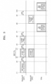
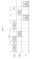
- FIGS. 3 and 4 are timing diagrams showing multiple access point (MAP) sounding according to embodiments.
- MAP multiple access point
- FIGS. 3 and 4 it is on the premise that the first access point AP1 is a sharing AP, the second access point AP2 is a shared AP, and the first access point AP1, the second access point AP2, and stations STAs participate in MAP sounding.
- FIGS. 3 and 4 are merely embodiments, aspects of the inventive concept are not limited thereto, and aspects of the inventive concept may be applied to a MAP network including a greater number of shared AP.
- the first access point AP1 may transmit a MAP network frame to the second access point AP2 and the stations STAs.
- the second access point AP2 and the stations STAs may receive the MAP network frame, obtain information needed for MAP sounding from the MAP network frame and prepare for MAP sounding based on the obtained information.
- the first access point AP1 may transmit a first NDP to the stations STAs.
- SIFS short interframe space
- the second access point AP2 may transmit a second NDP to the stations STAs in parallel with the first access point AP1 based on an NDP transmission scheme identified from the MAP network frame. For example, in a NDP transmission period NDP_TPa between the time point t31 and a time point t41, the first access point AP1 and the second access point AP2 may simultaneously transmit a first NDP and a second NDP to the stations STAs, respectively.
- the first NDP and the second NDP may be coordinated by the first access point AP1 and the second access point AP2 to be transmitted orthogonally with respect to each other to avoid mutual interference.
- first NDP and the second NDP may be coordinated by the first access point AP1 and the second access point AP2, such that first subcarriers for transmission of the first NDP and second subcarriers for transmission of the second NDP are interleaved with respect to each other to avoid mutual interference.
- the stations STAs may identify the first NDP and the second NDP based on information obtained from the MAP network frame.
- the stations STAs may each generate first channel state information by estimating a first channel state between itself and the first access point AP1 by using the first NDP.
- the stations STAs may each generate second channel state information by estimating a second channel state between itself and the second access point AP2 by using the second NDP.
- the first access point AP1 may transmit a first MAP trigger frame to the stations STAs.
- the first MAP trigger frame may correspond to a beamforming report poll (BFRP) trigger frame.
- BFRP beamforming report poll
- the stations STAs may each transmit a first MAP sounding feedback including the first channel state information to the first access point AP1 in response to the first MAP trigger frame.
- a MAP sounding feedback may also be referred to as a MAP feedback frame.
- the second access point AP2 may transmit a second MAP trigger frame to the stations STAs.
- the second MAP trigger frame may correspond to a BFRP trigger frame.
- the stations STAs may each transmit a second MAP sounding feedback including the second channel state information to the second access point AP2 in response to the second MAP trigger frame.
- the first access point AP1 and the second access point AP2 may perform a MAP interference enhancing operation based on the first MAP sounding feedback and the second MAP sounding feedback received from the stations STAs.
- the first access point AP1 may transmit a MAP network frame to the second access point AP2 and the stations STAs.
- the second access point AP2 and the stations STAs may receive the MAP network frame, obtain information needed for MAP sounding from the MAP network frame and prepare for MAP sounding based on obtained information.
- the first access point AP1 may transmit a first NDP to the stations STAs.
- the second access point AP2 may transmit a second NDP to the stations STAs after the first access point AP1 transmits the first NDP, based on a NDP transmission scheme identified from the MAP network frame. For example, in a NDP transmission period NDP_TPb between the time point t32 and a time point t42, the first access point AP1 and the second access point AP2 may sequentially transmit a first NDP and a second NDP to the stations STAs.
- the transmission of the first NDP does not overlap the transmission of the second NDP in terms of time
- aspects of the inventive concept are not limited thereto, and the end (i.e., a portion) of the transmission of the first NDP may overlap the beginning of the transmission of the second NDP in terms of time.
- information regarding an NDP transmission sequence may be included in the MAP network frame.
- the length of the NDP transmission period NDP_TPa of FIG. 3 is smaller than the length of the NDP transmission period NDP_TPb of FIG. 4 , when a channel state in a MAP network is poor, the probability that the stations STAs fail to properly receive the first NDP and the second NDP in the NDP transmission period NDP_TPa of FIG. 3 may be higher than the probability that the stations STAs fail to properly receive the first NDP and the second NDP in the NDP transmission period NDP_TPb.
- the first access point AP1 which is a sharing AP, may determine an NDP transmission scheme in consideration of the trade-off as described above. Embodiments related thereto will be described later with reference to FIGS. 6A and 6B .
- the stations STAs may identify the first NDP and the second NDP based on information obtained from the MAP network frame.
- the stations STAs may each generate first channel state information by estimating a first channel state between itself and the first access point AP1 by using the first NDP.
- the stations STAs may each generate second channel state information by estimating a second channel state between itself and the second access point AP2 by using the second NDP.
- the first access point AP1 may transmit a first MAP trigger frame to the stations STAs.
- the first MAP trigger frame may correspond to a BFRP trigger frame.
- the stations STAs may each transmit a first MAP sounding feedback including the first channel state information to the first access point AP1 in response to the first MAP trigger frame.
- the second access point AP2 may transmit a second MAP trigger frame to the stations STAs.
- the second MAP trigger frame may correspond to a BFRP trigger frame.
- the stations STAs may each transmit a second MAP sounding feedback including the second channel state information to the second access point AP2 in response to the second MAP trigger frame.
- the first access point AP1 and the second access point AP2 may perform a MAP interference enhancing operation based on the first MAP sounding feedback and the second MAP sounding feedback received from the stations STAs.
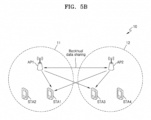
- FIGS. 5A and 5B are diagrams for describing a MAP interference enhancing operation performed based on channel state information collected through MAP sounding, according to an embodiment.
- descriptions identical to those already given above with reference to FIG. 1 will be omitted.
- FIG. 5A shows a coordinated beamforming operation of the first access point AP1.
- the first access point AP1 may generated beamformed data DATA based on MAP sounding feedbacks received through MAP sounding from the first station STA1 and the second station STA2 in the first BSS 11 and transmit the beamformed data DATA to the first station STA1 and the second station STA2.
- the first access point AP1 may perform null steering based on MAP sounding feedbacks received through MAP sounding from the third station STA3 and the fourth station STA4 in the second BSS 12.
- the null steering may be defined as an operation of coordinating beamforming matrix of a signal transmitted from the first access point AP1, such that the corresponding signal does not interfere with communication between the second access point AP2 and the third station STA3 and the fourth station STA4.
- a signal transmitted based on null steering may be measured as received power close to 0 at the third station STA3 after passing through a channel between the first access point AP1 and the third station STA3.
- FIG. 5B shows a joint transmission operation between the first access point AP1 and the second access point AP2.
- the first access point AP1 and the second access point AP2 may perform backhaul data sharing to share data to be transmitted to the first station STA1 and the third station STA3.
- the first access point AP1 and the second access point AP2 may perform a j oint transmission operation in cooperation with each other based on MAP sounding feedbacks received from the first station STA1 in the first BSS 11 through MAP sounding.
- the first access point AP1 and the second access point AP2 may perform a joint transmission operation in cooperation with each other based on MAP sounding feedbacks received from the third station STA3 in the second BSS 12 through MAP sounding.
- FIGS. 5A and 5B merely show examples of a MAP interference enhancing operation, and aspects of the inventive are is not limited thereto. There may be more examples of a MAP interference enhancing operation, and, in various examples, MAP sounding according to embodiments may be used.
- FIGS. 6A and 6B are flowcharts of a method for a sharing AP to determine an NDP transmission scheme, according to an embodiment.
- a sharing AP may estimate the channel state of a MAP network.
- the sharing AP may estimate the channel state of a MAP network by using previous channel states with respect to stations within its own BSS.
- the sharing AP may estimate the channel state of a MAP network by collecting previous channel states with respect to stations in other BSSs from at least one shared AP.
- a scheme by which the sharing AP estimates the channel state of a MAP network may be specialized for determining an NDP transmission scheme in MAP sounding. For example, the scheme for estimating the channel state of a MAP network focuses on determination of which of a relatively short NDP transmission period NDP_TPa of FIG. 3 and a relatively long NDP transmission period NDP_TPb of FIG. 4 is appropriate, and thus the amount of calculation needed for estimation of the channel state of the MAP network may be minimized.
- the sharing AP may determine an NDP transmission scheme based on the channel state estimated in operation S100a. For example, when the channel state of the MAP network is poorer than a reference value, the sharing AP may determine a first scheme in which APs sequentially transmit NDPs to stations in a certain sequence as the NDP transmission scheme. Also, when the channel state of the MAP network satisfies or is better than the reference value, the sharing AP may determine a second scheme in which APs simultaneously transmit NDPs to stations as the NDP transmission scheme.
- the sharing AP may generate a MAP network frame indicating the NDP transmission scheme determined in operation S110a.
- the sharing AP may set a particular subfield (e.g., an NDP type subfield) of sharing information field of the MAP network frame to a value indicating a determined NDP transmission scheme.
- the sharing AP may identify the maximum length of an NDP transmission period supported by the MAP network.
- the maximum length of an NDP transmission period supported by the MAP network may be pre-set in consideration of the channel state or a network environment.
- the sharing AP may obtain the maximum length of a NDP transmission period in advance from the MAP network.
- the sharing AP may determine an NDP transmission scheme based on the maximum length identified in operation S100b. For example, the sharing AP may compare the identified maximum length with an expected length of the NDP transmission period according to the above-stated first scheme and, based on a result of the comparison, determine whether to use the first scheme or the second scheme as the NDP transmission scheme. For example, the sharing AP may determine the above-stated first scheme as the NDP transmission scheme when the expected length of the NDP transmission period according to the first scheme is the same or shorter than the identified maximum length. The sharing AP may determine the above-stated second scheme as the NDP transmission scheme when the expected length of the NDP transmission period according to the first scheme is longer than the identified maximum length.
- the sharing AP may generate a MAP network frame indicating the NDP transmission scheme determined in operation S110b.
- the channel state of the MAP network of FIG. 6A and the maximum length of the NDP transmission period supported by the MAP network of FIG. 6B may be equally considered or different weights may be applied thereto to determine the NDP transmission scheme.
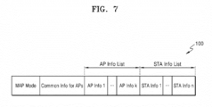
- FIG. 7 is a diagram showing a MAP network frame 100 according to an embodiment.
- the MAP network frame 100 may include a MAP mode field, a common information field regarding APs, a plurality of AP information fields, and a plurality of STA information fields.
- the plurality of AP information fields may include first to k-th (where k is an integer greater than or equal to 1) AP information fields, and the plurality of STA information fields may include first to n-th (where n is an integer greater than or equal to 2) STA information fields.
- the number of the plurality of AP information fields may correspond to the number of APs participating in MAP sounding, and the number of the plurality of STA information fields may correspond to the number of STAs participating in MAP sounding.
- the plurality of AP information fields may be referred to as an AP information list, and the plurality of STA information fields may be referred to as an STA information list.
- the MAP mode field may be a field indicating which MAP mode the MAP network frame 100 is to operate in.
- MAP modes may include a coordinated-spatial reuse (c-SR) mode, a coordinated-orthogonal frequency division multiplexing (c-OFDMA) mode, a coordinated-beamforming (c-BF) mode, a joint transmission mode, and a MAP sounding mode.
- the sharing AP may set the MAP mode field to a value indicating the MAP sounding mode, thereby informing APs and STAs participating in MAP sounding that the MAP network frame 100 is to operate in the MAP sounding mode.
- the common information field may include information commonly needed for APs to perform MAP sounding.
- the common information field may include information needed for APs to generate and transmit NDPs. A detailed embodiment thereof will be described later in FIG. 10 .
- an AP information field may include information needed for an AP having a particular BSS ID to generate an NDP.
- the AP information field may include information for STAs to identify that an NDP received by the STAs is an NDP transmitted from a particular AP. A detailed embodiment thereof will be described later in FIG. 11 .
- an STA information field may include information needed for an STA having a particular STA ID to estimate channel states by using NDPs received from APs. A detailed embodiment thereof will be described later in FIG. 12 .
- a shared AP may confirm that the MAP network frame 100 is to operate in the MAP sounding mode based on the value of the MAP mode field of the MAP network frame 100, determine an NDP transmission scheme from the common information field of the MAP network frame 100, and transmit an NDP to STAs based on an identified NDP transmission scheme.
- the MAP network frame 100 of FIG. 7 is merely an example embodiment, and aspects of the inventive concept are not limited thereto.
- the arrangement order of fields of the MAP network frame 100 may be variously changed, and the MAP network frame 100 may further include fields needed for MAP sounding.
- a sharing AP may generate information needed for at least one shared AP and STAs for MAP sounding, appropriately arrange generated information in fields of the MAP network frame 100, and transmit the MAP network frame 100 to the at least one shared AP and the STAs.
- a shared AP may identify a value indicating an NDP transmission scheme from the common information field of the MAP network frame 100 in response to the value of the MAP mode field of the MAP network frame 100 indicating a MAP sounding mode.
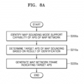
- FIGS. 8A and 8B are flowcharts of a method for a sharing AP to determine a target AP participating in MAP sounding, according to an embodiment.
- a sharing AP may identify the MAP sounding mode support capability of APs of a MAP network. For example, the sharing AP may receive information indicating a MAP sounding mode support capability from APs and identify the MAP sounding mode support capability of each of the APs based on received information.
- the sharing AP may determine target APs for MAP sounding based on a result of the identification in operation S200a.
- target APs may be defined as APs determined by a sharing AP to participate in MAP sounding.
- Target APs may correspond to shared APs.
- the sharing AP may generate MAP network frames indicating the target APs. For example, the sharing AP may place AP information fields corresponding to the target APs in the MAP network frame. The target APs may recognize that they need to participate in MAP sounding from AP information fields of the MAP network frame.
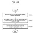
- the sharing AP may measure the interference environment of the MAP network.
- the sharing AP may measure the interference environment of the MAP network by measuring the degree of interference between APs of the MAP network.
- the sharing AP may determine target APs for MAP sounding based on the interference environment measured in operation S200b. For example, the sharing AP may determine APs corresponding to degrees of interference equal to or greater than a reference value from among APs based on a measured interference environment as target APs. According to some embodiments, the sharing AP may determine a larger number of target APs as the overall degree of interference in the measured interference environment increases.
- the sharing AP may generate a MAP network frame indicating the target APs.
- the MAP sounding mode support capability of APs of FIG. 8A and the measured interference environment of FIG. 8B may be equally considered or different weights may be applied thereto to determine target APs.
- FIGS. 9A and 9B are flowcharts of a method for a sharing AP to determine a target STA participating in MAP sounding, according to an embodiment.
- a sharing AP may identify the MAP sounding mode support capability of STAs in BSSs of APs of a MAP network. For example, the sharing AP may receive information indicating the MAP sounding mode support capability of STAs within its own BSS from APs and confirm the MAP sounding mode support capability of each STA based on received information. According to some embodiments, the sharing AP may also receive information indicating MAP sounding mode support capability directly from STAs.
- the sharing AP may determine target STAs for MAP sounding based on a result of the identification in operation S300a.
- target STAs may be defined as STAs determined by a sharing AP to participate in MAP sounding.
- the sharing AP may generate MAP network frames indicating the target STAs. For example, the sharing AP may place STA information fields corresponding to the target STAs in the MAP network frame. The target STAs may recognize that they need to participate in MAP sounding from STA information fields of the MAP network frame.
- the sharing AP may measure the interference environment of the MAP network.
- the sharing AP may measure the interference environment of the MAP network by measuring the degree of interference of communication between APs and STAs of the MAP network.
- the sharing AP may determine target STAs for MAP sounding based on the interference environment measured in operation S300b. For example, the sharing AP may determine STAs corresponding to degrees of interference equal to or greater than a reference value from among STAs based on a measured interference environment as target STAs. According to some embodiments, the sharing AP may determine a larger number of target STAs as the overall degree of interference in the measured interference environment increases.
- the sharing AP may generate MAP network frames indicating the target STAs.
- the MAP sounding mode support capability of STAs of FIG. 9A and the measured interference environment of FIG. 9B may be equally considered or different weights may be applied thereto to determine target STAs.
- FIG. 10 is a diagram showing a common information field 110 included in the MAP network frame 100 of FIG. 7 .
- the common information field 110 may include a bandwidth (BW) subfield, an NDP type subfield, an NDP format type subfield, a BSS color subfield, and an AP information number subfield.
- BW bandwidth
- the BW subfield may indicate the bandwidth of NDPs transmitted from APs.
- the bandwidth subfield may be omitted in the common information field 110 and a BW subfield may be included in each of AP information fields.
- the NDP type subfield may indicate an NDP transmission scheme.
- the NDP type subfield may indicate that an NDP transmission scheme is a 'joint NDP-11be-like LTFs' scheme, a 'joint NDP sounding-subcarrier interleaved LTFs' scheme, or a 'serial NDP transmission' scheme.
- the NDP format type subfield may indicate a protocol data unit (PPDU) format type of an NDP.
- PPDU protocol data unit
- the NDP format type subfield may indicate any one of a format type complying with UHR sounding and an amendment type of a format complying with sounding of a next generation of UHR.
- the BSS color subfield may indicate a value to be set in the BSS color field in the preamble of an NDP when the NDP transmission scheme is a 'joint NDP transmission' scheme in which APs simultaneously transmit NDPs.
- the AP information number subfield may indicate the number of APs (including a sharing AP and at least one shared AP) participating in MAP sounding.
- the value of the AP information number subfield may indicate the number of AP information fields in an AP information list.
- the common information field 110 of FIG. 10 is merely an example embodiment, aspects of the inventive concept are not limited thereto.
- the arrangement order of subfields of the common information field 110 may be variously changed, and the common information field 110 may further include subfields commonly needed for MAP sounding.
- FIG. 11 is a diagram showing an AP information field 120 included in the MAP network frame 100 of FIG. 7 .
- the AP information field 120 may include a BSS ID subfield, a BW subfield, a STA information number subfield, a punctured channel information subfield for an NDP, a guard interval (GI) + long training field (LTF) size subfield, a UHR-LTF symbol number subfield, a number of spatial stream (NSS) subfield for an NDP, and an LTF specific information subfield for an NDP.
- a BSS ID subfield a BW subfield
- STA information number subfield a punctured channel information subfield for an NDP
- GI guard interval
- LTF long training field
- UHR-LTF symbol number subfield a number of spatial stream (NSS) subfield for an NDP
- LTF specific information subfield for an NDP LTF specific information subfield for an NDP.
- the BSS ID subfield may be a subfield for enabling an AP having the value of the BSS ID subfield as a BSS ID from among APs participating in MAP sounding to identify a corresponding AP information field 120.
- an AP may identify the AP information field 120 allocated thereto through the BSS ID subfield.
- the BSS ID subfield may be replaced with a MAP ID subfield.
- the MAP ID subfield may include a newly allocated ID to identify a corresponding AP through MAP sounding signaling previously performed for MAP sounding (or MAP communication).
- the BSS ID subfield may be implemented in various ways, such that APs participating in MAP sounding may identify their own AP information fields 120.
- the BW subfield may indicate the bandwidth of an NDP transmitted by an AP having the value of the BSS ID subfield as a BSS ID.
- the bandwidth subfield may be omitted in the AP information field 120 and may be placed in the common information field 110 of FIG. 10 .
- the STA information number subfield may indicate the number of STAs participating in MAP sounding from among STAs associated with the AP having the value of the BSS ID subfield as the BSS ID.
- STAs related to an AP may be understood as STAs within a BSS of the corresponding AP.
- the punctured channel information subfield may indicate punctured channel information regarding an NDP transmitted from the AP having the value of the BSS ID subfield as the BSS ID.
- the GI+LTF size subfield may indicate a GI duration and a UHR-LTF size of an NDP transmitted from the AP having the value of the BSS ID subfield as the BSS ID.
- the UHR-LTF symbol number subfield may indicate the number of UHR-LTF symbols of an NDP transmitted from the AP having the value of the BSS ID subfield as the BSS ID.
- the NSS subfield may indicate the number of spatial streams of an NDP transmitted by the AP having the value of the BSS ID subfield as the BSS ID.
- the LTF specific information subfield may indicate specific information needed for the AP having the value of the BSS ID subfield as the BSS ID to generate an NDP.
- the specific information may indicate a turn in which a corresponding shared AP is set to transmit an NDP in the 'serial NDP transmission' scheme, how a global antenna index of the corresponding shared AP is configured in the 'joint NDP-11be-like LTFs' scheme, or how a subcarrier index for NDP transmission is set in the 'joint NDP sounding-subcarrier interleaved LTFs' scheme.
- the punctured channel information subfield, the GI+LTF size subfield, the UHR-LTF symbol number subfield, and the NSS subfield may be defined as individual settings for the AP having the value of the BSS ID subfield as the BSS ID to generate an NDP or concepts included in the individual settings.
- the AP information field 120 of FIG. 11 is merely an example embodiment, aspects of the inventive concept are not limited thereto.
- the arrangement order of subfields of the AP information field 120 may be variously changed, and the AP information field 120 may further include subfields individually needed by an AP for MAP sounding.
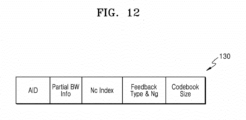
- FIG. 12 is a diagram showing an STA information field 130 included in the MAP network frame 100 of FIG. 7 .
- the STA information field 130 may include an AID subfield, a partial BW information subfield, an Nc index subfield, a feedback type & N_guard (Ng) subfield, and a codebook size subfield.
- the AID subfield may be a subfield for enabling an STA having the value of the AID subfield as a STA ID from among STAs participating in MAP sounding to identify a corresponding STA information field 130.
- an STA may identify the STA information field 130 allocated thereto through the AID subfield.
- the partial BW information subfield may indicate a partial BW or a frequency domain of a MAP sounding feedback transmitted by an STA having the value of the AID subfield as the STA ID.
- the Nc index subfield may indicate the number of columns of a compressed beamforming feedback matrix or space-time streams during generation of a MAP sounding feedback by the STA having the value of the AID subfield as the STA ID.
- the Nc index subfield may indicate the number of columns of a compressed beamforming feedback matrix when the feedback type is single user (SU) or multiple users (MU) and indicate the number of space-time streams in a channel quality information (CQI) report when the feedback type is CQI.
- SU single user
- MU multiple users
- the feedback type & Ng subfield may indicate a feedback type and the value of Ng when the STA having the value of the AID subfield as the STA ID generates a MAP sounding feedback.
- the codebook size subfield may indicate quantization resolution when the STA having the value of the AID subfield as the STA ID generates a MAP sounding feedback.
- the STA information field 130 of FIG. 12 is merely an example embodiment, aspects of the inventive concept are not limited thereto.
- the arrangement order of subfields of the STA information field 130 may be variously changed, and the STA information field 130 may further include subfields individually needed by an STA for MAP sounding.
- FIG. 13 is a diagram showing an arrangement relationship between AP information fields AP Info 1 to AP Info k and STA information fields STA Info 1 to STA Info n in a MAP network frame 200, according to an embodiment.
- a first AP information field AP Info 1 may be associated with a first STA information field STA Info 1 and a second STA information field STA Info 2
- a second AP information field AP Info 2 may be associated with a third STA information field STA Info 3
- a k-th AP information field AP Info k may be associated with an (n-1)-th STA information field STA Info n-1 and an n-th STA information field STA Info n.
- the association between an AP information field with an STA information field may be understood that an STA corresponding to the STA information field belongs to an STA information field in a BSS of an AP corresponding to the AP information field.
- the STA information fields STA Info 1 to STA Info n may be arranged in correspondence to the arrangement sequence of the AP information fields AP Info 1 to AP Info k associated therewith.
- the AP information fields AP Info 1 to AP Info k and the STA information fields STA Info 1 to STA Info n may be variously arranged in the MAP network frame 200 to be easily identified by APs and STAs participating in MAP sounding.
- FIG. 14 is a flowchart showing a method of identifying STA information regarding a station, according to an embodiment.
- a station may receive a MAP network frame.
- the station may determine whether there are a plurality of STA information fields having the same STA ID as its own STA ID.
- the station may identify an STA information field assigned thereto based on the arrangement sequence of AP information fields in an AP information list. For example, the station may identify a position of an AP information field assigned to an AP managing a BSS to which the station belongs in the AP information list and identify an STA information field assigned to the station based on a result of the identification and the STA ID.
- the station may identify that the first STA information field from among the three STA information fields as an STA information field allocated to the station.
- the station may identify an STA information field having the same STA ID as the STA ID of the station as an STA information field assigned to the station.
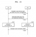
- FIG. 15 is a flowchart of an operation method in a MAP network, according to an embodiment. It is assumed that the MAP network includes the first access point AP1 and the second access point AP2.
- the first access point AP1 and the second access point AP2 may transmit and receive MAP network-related information.
- the first access point AP1 and the second access point AP2 may perform signaling for determining a sharing AP.
- the first access point AP1 may operate as a sharing AP
- the second access point AP2 may operate as a shared AP.
- the first access point AP1 may transmit a MAP network frame to the second access point AP2.
- FIG. 16 is a diagram showing examples of apparatuses for wireless communication according to an embodiment.
- FIG. 16 shows an Internet of Things (IoT) network system including a home device (i.e., gadgets) 311, a home appliance 312, an entertainment device 313, and an access point 315.
- IoT Internet of Things
- the apparatuses for wireless communication of FIG. 16 may prepare for MAP sounding by transmitting and receiving a MAP network frame. Also, the apparatuses for wireless communication of FIG. 16 may perform MAP sounding based on an NDP transmission scheme indicated by the MAP network frame. Therefore, overall communication throughput of the apparatuses for wireless communication may be improved.
- FIG. 17 is a block diagram showing an apparatus 1000 according to an embodiment.
- the apparatus 1000 of FIG. 17 may be a station or an access point as described above.
- the apparatus 1000 may include a radio frequency integrated circuit (RFIC) 1100, a receiving circuit 1200, a demodulator 1300, a transmitting circuit 1400, a processor 1500, and a MAC-PHY Interface (MPI) 1600.
- RFIC radio frequency integrated circuit
- FIG. 17 shows that components 1100, 1200, 1300, 1400, 1500, and 1600 are separated from one another, this is merely an example embodiment, and aspects of the inventive concept are not limited thereto.
- the components 1100, 1200, and 1300, 1400, 1500, 1600 may be implemented to be included in one chip (e.g., a modem chip).
- the receiving circuit 1200 may include a receiving radio (RX Radio) control circuit 1201, a frequency error correction circuit 1202, a clear-channel-assessment (CCA) circuit 1203, and a synchronization circuit 1204.
- RX Radio receiving radio
- CCA clear-channel-assessment
- the demodulator 1300 may include a fast Fourier transform (FFT) circuit 1301, a channel estimator (CE) 1302, a signal to noise ratio (SNR) measuring circuit 1303, a channel tracker 1304, a reception beamforming (RX BF) circuit 1305, a pilot discrete Fourier transform (DFT) circuit 1306, a symbol demodulator 1307, a frame format detector 1308, a frequency/time tracker 1309, and log-likelihood ratio (LLR) demapper 1310.
- FFT fast Fourier transform
- CE channel estimator
- SNR signal to noise ratio
- RX BF reception beamforming
- DFT pilot discrete Fourier transform
- symbol demodulator 1307 a symbol demodulator 1307
- frame format detector 1308 a frequency/time tracker 1309
- LLR log-likelihood ratio
- the transmitting circuit 1400 may include a transmission radio (TX Radio) control circuit 1401, an inverse fast Fourier transform (IFFT) circuit 1402, a low-density parity-check (LDPC) encoder 1403, a convolutional encoder 1404, a transmission beamforming (TX BF) circuit 1405, a data encoder 1406, and a preamble circuit 1407.
- TX Radio transmission radio
- IFFT inverse fast Fourier transform
- LDPC low-density parity-check
- TX BF transmission beamforming circuit 1405
- data encoder 1406 and a preamble circuit 1407.
- the processor 1500 may include an institute of electrical and electronics engineers (IEEE) decoder 1501, a signal (SIG) decoder 1502, an LDPC decoder 1503, a Viterbi decoder 1504, and a data decoder 1505.
- IEEE institute of electrical and electronics engineers
- the transmitting circuit 1400 may generate the above-stated MAP network frame by using at least one of internal components 1401, 1402, 1403, 1404, 1405, 1406, and 1407 and output the MAP network frame through the RFIC 1100.
- the processor 1500 may decode a received MAP network frame by using at least one of internal components 1501, 1502, 1503, 1504, and 1505 and extract information needed for MAP sounding.
- the transmitting circuit 1400 may generate an NDP by using at least one of the internal configurations 1401, 1402, 1403, 1404, 1405, 1406, and 1407 based on information extracted by the processor 1500 and output the NDP through the RFIC 1100 according to the NDP transmission scheme described above.
- the demodulator 1300 may estimate a channel state based on a received NDP by using at least one of internal components 1301, 1302, 1303, 1304, 1305, 1306, 1307, 1308, 1309, and 1310 and generate channel state information.
- the transmitting circuit 1400 may generate a MAP sounding feedback including channel state information by using at least one of the internal components 1401, 1402, 1403, 1404, 1405, 1406, and 1407 and output the MAP sounding feedback through the RFIC 1100.
Landscapes
- Engineering & Computer Science (AREA)
- Signal Processing (AREA)
- Computer Networks & Wireless Communication (AREA)
- Mobile Radio Communication Systems (AREA)
Applications Claiming Priority (2)
| Application Number | Priority Date | Filing Date | Title |
|---|---|---|---|
| KR20230016268 | 2023-02-07 | ||
| KR1020230067725A KR20240123727A (ko) | 2023-02-07 | 2023-05-25 | Map 네트워크에서의 사운딩을 위한 장치 및 방법 |
Publications (1)
| Publication Number | Publication Date |
|---|---|
| EP4415296A1 true EP4415296A1 (de) | 2024-08-14 |
Family
ID=89843715
Family Applications (1)
| Application Number | Title | Priority Date | Filing Date |
|---|---|---|---|
| EP24155605.9A Pending EP4415296A1 (de) | 2023-02-07 | 2024-02-02 | Vorrichtung und verfahren zur sondierung in einem netzwerk mit mehreren zugangspunkten |
Country Status (2)
| Country | Link |
|---|---|
| US (1) | US20240267176A1 (de) |
| EP (1) | EP4415296A1 (de) |
Families Citing this family (2)
| Publication number | Priority date | Publication date | Assignee | Title |
|---|---|---|---|---|
| CN118614103A (zh) * | 2022-02-10 | 2024-09-06 | 松下电器(美国)知识产权公司 | 通信装置及通信方法 |
| WO2026063752A1 (ko) * | 2024-09-23 | 2026-03-26 | 엘지전자 주식회사 | 무선랜 시스템에서 협력 빔포밍을 위한 ppdu 송수신 방법 및 장치 |
Citations (2)
| Publication number | Priority date | Publication date | Assignee | Title |
|---|---|---|---|---|
| US20210359724A1 (en) * | 2019-04-22 | 2021-11-18 | Mediatek Singapore Pte. Ltd. | Device and method for multi-access point collaborative sounding in a wireless network |
| US20210409179A1 (en) * | 2019-03-08 | 2021-12-30 | Huawei Technologies Co., Ltd. | Communication method and communication apparatus applied to wireless communication system |
Family Cites Families (8)
| Publication number | Priority date | Publication date | Assignee | Title |
|---|---|---|---|---|
| KR20250142473A (ko) * | 2018-11-08 | 2025-09-30 | 인터디지탈 패튼 홀딩스, 인크 | 무선 로컬 영역 네트워크(wlans)에서 다중 액세스 포인트(multi-ap) 조정을 위한 시스템, 방법 및 장치 |
| CN113747485A (zh) * | 2020-05-30 | 2021-12-03 | 华为技术有限公司 | 多ap协作传输的信道探测方法及相关装置 |
| US20240223250A1 (en) * | 2021-04-23 | 2024-07-04 | Interdigital Patent Holdings, Inc. | Multi-ap channel sounding feedback procedures for wlan systems |
| KR20240004804A (ko) * | 2021-04-30 | 2024-01-11 | 인터디지탈 패튼 홀딩스, 인크 | Wlan 시스템을 위한 다중 ap 채널 사운딩 절차 |
| US20240275566A1 (en) * | 2021-06-07 | 2024-08-15 | Interdigital Patent Holdings, Inc. | Enhanced channel sounding reports for wlan systems |
| CA3222501A1 (en) * | 2021-06-18 | 2022-12-22 | Interdigital Patent Holdings, Inc. | Enhanced channel sounding protocols for wlan systems |
| MX2024001069A (es) * | 2021-08-04 | 2024-02-27 | Panasonic Ip Corp America | Dispositivo de comunicacion y metodo de comunicacion. |
| TW202327301A (zh) * | 2021-11-05 | 2023-07-01 | 美商內數位專利控股公司 | 用於wlan系統的資料驅動探測回授報告 |
-
2024
- 2024-02-01 US US18/430,361 patent/US20240267176A1/en active Pending
- 2024-02-02 EP EP24155605.9A patent/EP4415296A1/de active Pending
Patent Citations (2)
| Publication number | Priority date | Publication date | Assignee | Title |
|---|---|---|---|---|
| US20210409179A1 (en) * | 2019-03-08 | 2021-12-30 | Huawei Technologies Co., Ltd. | Communication method and communication apparatus applied to wireless communication system |
| US20210359724A1 (en) * | 2019-04-22 | 2021-11-18 | Mediatek Singapore Pte. Ltd. | Device and method for multi-access point collaborative sounding in a wireless network |
Also Published As
| Publication number | Publication date |
|---|---|
| US20240267176A1 (en) | 2024-08-08 |
Similar Documents
| Publication | Publication Date | Title |
|---|---|---|
| US20230354046A1 (en) | Generalized distributed multi-user (mu) transmissions | |
| US11452063B2 (en) | Null data packet (NDP) ranging measurement feedback | |
| US12058230B2 (en) | Apparatus and method for signaling expansion in wireless local area network system | |
| US10277424B2 (en) | Uplink sounding in a wireless local area network | |
| EP4415296A1 (de) | Vorrichtung und verfahren zur sondierung in einem netzwerk mit mehreren zugangspunkten | |
| US10778472B2 (en) | Opportunistic measurement and feedback in a wireless local area network | |
| US20220345904A1 (en) | Apparatus and method for channel sounding | |
| US9998195B2 (en) | Station (STA), access point (AP) and method for uplink sounding | |
| US12250589B2 (en) | Apparatus and method for channel sounding | |
| EP4422110A1 (de) | Verfahren und vorrichtung zur sondierung in einem kartennetzwerk | |
| CN107852222B (zh) | 通过频率分集进行传输的系统和方法 | |
| US20250203650A1 (en) | Apparatus and method for transmitting latency-sensitive data in wireless network system | |
| US20240030974A1 (en) | Apparatus and method of uplink beamforming in wireless local area network system | |
| US12425270B2 (en) | Apparatus and method for channel sounding | |
| WO2025010537A1 (en) | Channel state information feedback with time and frequency offset compensation | |
| KR20230127122A (ko) | 채널 사운딩을 위한 장치 및 방법 | |
| KR20240123727A (ko) | Map 네트워크에서의 사운딩을 위한 장치 및 방법 | |
| CN118473865A (zh) | 操作无线局域网(wlan)系统中的第一设备的方法 | |
| KR20220145729A (ko) | 채널 사운딩을 위한 장치 및 방법 | |
| US20250168881A1 (en) | Apparatus and method for sounding in multiple access points (map) network | |
| KR20240130580A (ko) | Map 네트워크에서의 사운딩을 위한 장치 및 방법 | |
| KR20220001412A (ko) | Wlan 시스템에서 사용자의 효율적인 채널 상태 정보 피드백을 지원하기 위한 장치 및 방법 | |
| CN118540186A (zh) | 用于map网络中的探测的方法及设备 | |
| US20250212151A1 (en) | Apparatus and method for transmitting latency-sensitive data in wireless local area network (wlan) system | |
| KR20240012274A (ko) | Wlan 시스템에서 업링크 빔포밍을 위한 장치 및 방법 |
Legal Events
| Date | Code | Title | Description |
|---|---|---|---|
| PUAI | Public reference made under article 153(3) epc to a published international application that has entered the european phase |
Free format text: ORIGINAL CODE: 0009012 |
|
| STAA | Information on the status of an ep patent application or granted ep patent |
Free format text: STATUS: THE APPLICATION HAS BEEN PUBLISHED |
|
| AK | Designated contracting states |
Kind code of ref document: A1 Designated state(s): AL AT BE BG CH CY CZ DE DK EE ES FI FR GB GR HR HU IE IS IT LI LT LU LV MC ME MK MT NL NO PL PT RO RS SE SI SK SM TR |
|
| P01 | Opt-out of the competence of the unified patent court (upc) registered |
Free format text: CASE NUMBER: APP_66004/2024 Effective date: 20241213 |
|
| STAA | Information on the status of an ep patent application or granted ep patent |
Free format text: STATUS: REQUEST FOR EXAMINATION WAS MADE |
|
| 17P | Request for examination filed |
Effective date: 20250211 |
|
| GRAP | Despatch of communication of intention to grant a patent |
Free format text: ORIGINAL CODE: EPIDOSNIGR1 |
|
| STAA | Information on the status of an ep patent application or granted ep patent |
Free format text: STATUS: GRANT OF PATENT IS INTENDED |
|
| GRAS | Grant fee paid |
Free format text: ORIGINAL CODE: EPIDOSNIGR3 |
|
| INTG | Intention to grant announced |
Effective date: 20260310 |
|
| GRAA | (expected) grant |
Free format text: ORIGINAL CODE: 0009210 |
|
| STAA | Information on the status of an ep patent application or granted ep patent |
Free format text: STATUS: THE PATENT HAS BEEN GRANTED |