EP4415229A1 - Permanent magnet rotor and method for manufacturing the same - Google Patents
Permanent magnet rotor and method for manufacturing the same Download PDFInfo
- Publication number
- EP4415229A1 EP4415229A1 EP23155820.6A EP23155820A EP4415229A1 EP 4415229 A1 EP4415229 A1 EP 4415229A1 EP 23155820 A EP23155820 A EP 23155820A EP 4415229 A1 EP4415229 A1 EP 4415229A1
- Authority
- EP
- European Patent Office
- Prior art keywords
- section
- permanent magnet
- bearing
- cylindrical outer
- rotor
- Prior art date
- Legal status (The legal status is an assumption and is not a legal conclusion. Google has not performed a legal analysis and makes no representation as to the accuracy of the status listed.)
- Pending
Links
Images


Classifications
-
- H—ELECTRICITY
- H02—GENERATION; CONVERSION OR DISTRIBUTION OF ELECTRIC POWER
- H02K—DYNAMO-ELECTRIC MACHINES
- H02K1/00—Details of the magnetic circuit
- H02K1/06—Details of the magnetic circuit characterised by the shape, form or construction
- H02K1/22—Rotating parts of the magnetic circuit
- H02K1/27—Rotor cores with permanent magnets
- H02K1/2786—Outer rotors
- H02K1/2787—Outer rotors the magnetisation axis of the magnets being perpendicular to the rotor axis
- H02K1/2789—Outer rotors the magnetisation axis of the magnets being perpendicular to the rotor axis the rotor consisting of two or more circumferentially positioned magnets
- H02K1/2791—Surface mounted magnets; Inset magnets
-
- H—ELECTRICITY
- H02—GENERATION; CONVERSION OR DISTRIBUTION OF ELECTRIC POWER
- H02K—DYNAMO-ELECTRIC MACHINES
- H02K15/00—Processes or apparatus specially adapted for manufacturing, assembling, maintaining or repairing of dynamo-electric machines
- H02K15/02—Processes or apparatus specially adapted for manufacturing, assembling, maintaining or repairing of dynamo-electric machines of stator or rotor bodies
- H02K15/03—Processes or apparatus specially adapted for manufacturing, assembling, maintaining or repairing of dynamo-electric machines of stator or rotor bodies having permanent magnets
-
- H—ELECTRICITY
- H02—GENERATION; CONVERSION OR DISTRIBUTION OF ELECTRIC POWER
- H02K—DYNAMO-ELECTRIC MACHINES
- H02K21/00—Synchronous motors having permanent magnets; Synchronous generators having permanent magnets
- H02K21/12—Synchronous motors having permanent magnets; Synchronous generators having permanent magnets with stationary armatures and rotating magnets
- H02K21/22—Synchronous motors having permanent magnets; Synchronous generators having permanent magnets with stationary armatures and rotating magnets with magnets rotating around the armatures, e.g. flywheel magnetos
-
- H—ELECTRICITY
- H02—GENERATION; CONVERSION OR DISTRIBUTION OF ELECTRIC POWER
- H02K—DYNAMO-ELECTRIC MACHINES
- H02K5/00—Casings; Enclosures; Supports
- H02K5/04—Casings or enclosures characterised by the shape, form or construction thereof
- H02K5/16—Means for supporting bearings, e.g. insulating supports or means for fitting bearings in the bearing-shields
- H02K5/173—Means for supporting bearings, e.g. insulating supports or means for fitting bearings in the bearing-shields using bearings with rolling contact, e.g. ball bearings
- H02K5/1735—Means for supporting bearings, e.g. insulating supports or means for fitting bearings in the bearing-shields using bearings with rolling contact, e.g. ball bearings radially supporting the rotary shaft at only one end of the rotor
-
- H—ELECTRICITY
- H02—GENERATION; CONVERSION OR DISTRIBUTION OF ELECTRIC POWER
- H02K—DYNAMO-ELECTRIC MACHINES
- H02K7/00—Arrangements for handling mechanical energy structurally associated with dynamo-electric machines, e.g. structural association with mechanical driving motors or auxiliary dynamo-electric machines
- H02K7/08—Structural association with bearings
- H02K7/085—Structural association with bearings radially supporting the rotary shaft at only one end of the rotor
-
- H—ELECTRICITY
- H02—GENERATION; CONVERSION OR DISTRIBUTION OF ELECTRIC POWER
- H02K—DYNAMO-ELECTRIC MACHINES
- H02K2213/00—Specific aspects, not otherwise provided for and not covered by codes H02K2201/00 - H02K2211/00
- H02K2213/03—Machines characterised by numerical values, ranges, mathematical expressions or similar information
-
- H—ELECTRICITY
- H02—GENERATION; CONVERSION OR DISTRIBUTION OF ELECTRIC POWER
- H02K—DYNAMO-ELECTRIC MACHINES
- H02K7/00—Arrangements for handling mechanical energy structurally associated with dynamo-electric machines, e.g. structural association with mechanical driving motors or auxiliary dynamo-electric machines
- H02K7/08—Structural association with bearings
- H02K7/086—Structural association with bearings radially supporting the rotor around a fixed spindle; radially supporting the rotor directly
Definitions
- the invention relates to a permanent magnet rotor according to the preamble of independent claim 1.
- the invention furthermore relates to a method for manufacturing a permanent magnet rotor according to the preamble of independent claim 11.
- a known prior art permanent magnet rotor is disclosed in US2010133927A1 .
- the rotor is an external rotor comprising an annular side wall, an end cover directly connected to said annular side wall and a cavity formed between said side wall and said end cover.
- a plurality of openings are formed in the side wall and a plurality of magnetic tiles are received in the openings.
- a magnetic yoke shell is also disposed against said side wall, wherein said side wall and said end cover are integrally formed by injection molding.
- the permanent magnet rotor according to the invention as defined in claim 1 has the advantage of providing an improved fixing of the magnets to the rotor, or at least provides an alternative to known fixing arrangements or methods.
- a permanent magnet rotor for a motor comprising a generally cylindrical outer section and a bearing section arranged radially inwards of the generally cylindrical outer section for rotatably supporting the rotor, wherein the generally cylindrical outer section and the bearing section are connected by a generally radially extending cover wall, wherein the generally cylindrical outer section, the bearing section and the generally radially extending cover wall define at least partly a space for receiving a stator, the generally cylindrical outer section comprising: an annular ring made out of a magnetic material, a plurality of annularly disposed magnets arranged radially inwards of said annular ring and an inner wall arranged radially inwards of said magnets and having a substantially cylindrical inner surface, wherein each magnet has a first and a second end in the circumferential direction and is provided with a radially inwards facing surface having a central section and first and second tapered end sections in the circumferential direction, wherein
- the magnets are thus fixed to the annular ring via the overmolding of the polymer material.
- the substantially cylindrical inner surface of the inner wall may contain grooves or recesses formed during molding due to the tooling pins holding the magnets against the annular ring.
- the annular ring can be made for example out of steel forming a magnetic yoke.
- the magnets Due to the shape of the magnets with tapered end sections, the magnets can be fixed to the annular ring without the use of adhesive, as the overmolding polymer material can flow over the magnets to cover the entire inner surface of the generally cylindrical outer section.
- the tapered sections of the magnets facilitate the flow of the overmolding polymer material to the center section of the magnets, thus reducing the necessary thickness of the polymer material covering the magnets and in turn reducing the weight of the rotor.
- the overmolding polymer can in one embodiment completely enclose the magnets and the annular ring in order to protect these parts from contact with unwanted elements.
- the central section of the magnet extends over at least 40% of the magnet in the circumferential direction.
- the first and/or second tapered end section extends over at least 10% of the magnet in the circumferential direction. This ratio of tapered end section to non-tapered central section has been found to provide, when overmolded with the polymer material, a sufficient fixing of the magnet to the annular ring whilst enabling the covering of the entire magnet surface with a thin layer of polymer in order to reduce weight and minimizing the gap between the magnets and the stator.
- the bearing section has a central opening for receiving a rotationally fixed shaft.
- the bearing section can be supported on the fixed shaft by two axially spaced rolling element bearings.
- the bearing section comprises a bearing sleeve made out of metal for receiving an outer bearing race for one of the rolling element bearings.
- the bearing sleeve can have a profiled radial outer surface.
- the bearing section can additionally or alternatively comprise an outer bearing race of one of the rolling-element bearings.
- the annular ring, the magnets and at least one of the bearing sleeve or the outer bearing race are overmolded in one step by a polymer, whereby the generally radially extending cover wall is formed out of the polymer in the same step.
- a plurality of metallic threaded inserts for attaching a fan can be provided in the radially extending cover wall such that the threaded inserts are fixed in the cover wall by overmolding.
- annular ring made out of a magnetic material, preferably steel, can be provided with threaded attachment points for attaching a fan.
- a cooling fan motor comprising a stator having a stack of steel laminations and a plurality of winding coils arranged in circumferentially spaced slots in the steel laminations and a permanent magnet rotor according to any of the above embodiments of the invention.
- a cooling fan is attached to the radially extending cover wall via the threaded inserts molded into the radially extending cover wall.
- a method for manufacturing a permanent magnet rotor comprising a generally cylindrical outer section and a bearing section arranged radially inwards of the generally cylindrical outer section, whereby the generally cylindrical outer section and the bearing section are connected by a generally radially extending cover wall, the generally cylindrical outer section, the bearing section and the generally radially extending cover wall defining at least partly a space for receiving a stator, the method comprising the steps of:
- a plurality of metallic threaded inserts for attaching a fan are positioned in the molding tooling such that they are fixed in the radially extending cover wall formed in the overmolding step d).
- at least three of such threaded inserts are positioned in the molding tooling.
- an outer bearing race is positioned in the molding tooling such that it is overmolded by the polymer material in the overmolding step d).
- the assembly steps of the rotor with fan are reduced. For example, pressfitting of bearing parts can be avoided.
- the generally radially extending cover wall can be advantagously formed without metallic reinforcement. This is achieved by increasing the thickness of the cover wall and/or providing the cover wall with reinforcing ribs.
- the reinforcing ribs extend radially from the central opening in the cover wall to each of the plurality of metallic threaded inserts.
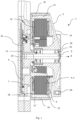
- FIG. 1 shows a sectional side view of a cooling fan motor 1 according to the invention.
- the cooling fan motor 1 can be used for example for cooling internal combustion engines or vehicle batteries.
- the cooling fan motor 1 comprises a permanent magnet rotor 2, a stator 3 and a control unit 4.
- the stator 3 comprises a stack of steel laminations 5 with circumferentially spaced slots for receiving winding coils 6.
- the stator 3 is attached to the housing 7 of the control unit 4.
- the control unit 4 is arranged on a first side of the stator 3 in the axial direction 8.
- the control unit 4 comprises a control circuit board 32, power switches and capacitors for supplying multi-phase current to the stator coils 6.
- a shaft 9 is fixedly attached to control unit housing 7 or is integrally formed therewith.
- the permanent magnet rotor 2 is arranged to rotate around the shaft 9.
- two rolling bearings 10, 11 are arranged at opposite axial ends of the rotor 7.
- the permanent magnet rotor 2 comprises a generally cylindrical outer section 12 and a bearing section 13 arranged radially inwards of the generally cylindrical outer section for rotatably supporting the rotor 2.
- the generally cylindrical outer section 12 and the bearing section 13 are connected by a generally radially extending cover wall 14, which is arranged on a second side of the stator 3 in the axial direction 8 opposite to the control unit 4.
- the generally cylindrical outer section 12, the bearing section 13 and the generally radially extending cover wall 14 define at least partly a space 15 for receiving the stator 3, such that the stator 3 is arranged radially between the generally cylindrical outer section 12 and the bearing section 13.
- the bearing section 13 has a central opening 31 for receiving the shaft 9, such that the rotor 2 is supported in the shaft via the two rolling bearings 10, 11.
- the generally cylindrical outer section 12 of the rotor 2 comprises an annular ring 16 made out of a magnetic material, e.g. steel, and a plurality of annularly disposed magnets 17 arranged radially inwards of said annular ring 16, preferably contacting the annular ring 16..
- An inner wall 18 of the cylindrical outer section 12 is arranged radially inwards of said magnets 17.
- each magnet 17 has a first end 19 and a second end 20 in the circumferential direction.
- Each magnet 17 has a central section 22 and first and second tapered end sections 23 in the circumferential direction.
- the distance of a radially inwards facing surface 21 of the magnets 17 to the rotation axis 24 of the rotor 2 increases in the tapered sections towards the respective first and second circumferential ends 19, 20, whereas the distance of the central section 22 of the radially inwards facing surface 21 to the rotation axis 24 remains constant.
- the central section 22 of the magnet extends over at least 40% of the magnet 17 in the circumferential direction.
- the first and second tapered end sections 23 each extend over at least 10% of the magnet in the circumferential direction. This ratio of tapered end section to non-tapered central section has been found to provide, when overmolded with the polymer material, a sufficient fixing of the magnet to the annular ring 16 whilst enabling the covering of the entire magnet surface with a thin layer of polymer in order to reduce weight and minimizing the gap between the magnets 17 and the stator 3.
- manufacturing the permanent magnet rotor 2 includes the steps of:
- Fig. 2 shows the above parts positioned in relation to each other before overmolding, the molding tooling is however not shown.
- the molding tooling is however not shown.
- the rotor 2 is shown after the overmolding step.
- the generally cylindrical outer section 12 has an inner wall 18 facing the stator 3 formed with the polymer material and having a substantially cylindrical radially inner surface 27.
- additional assembly steps e.g. fixing the magnets to the annular ring with adhesive and attaching bearing parts can be eliminated.
- the plurality of metallic threaded inserts 26 for attaching a fan can be provided in the radially extending cover wall 14 such that the threaded inserts 26 are fixed in the cover wall 14 by overmolding.
- the thickness of the inner wall 18 is substantially constant in the area of the central section 22 of the magnets 17 and increases in the area of the first and second tapered end sections 23 of the magnets 17 towards the first and second ends of the magnets 17 respectively.
- the inner wall 18 may contain grooves or recesses 28 formed during molding due to the tooling pins holding the magnets 17 against the annular ring 16.
- the shape of the magnets 17 with tapered end sections 23 enable the magnets 17 to be fixed to the annular ring 16 without the use of adhesive, as the overmolding polymer material can flow over the magnets 17 to cover the entire inner surface of the generally cylindrical outer section.
- the tapered sections 23 of the magnets facilitate the flow of the overmolding polymer material to the center section of the magnets, thus reducing the necessary thickness of the polymer material covering the magnets and in turn reducing the weight of the rotor 2.
- the overmolding polymer substantially completely encloses the magnets 17 and the annular ring 16 in order to protect these parts from contact with unwanted elements.
- the generally radially extending cover wall 14 is advantagously formed out of the polymer material without metallic reinforcement. This is achieved by increasing the thickness of the cover wall 14 and/or providing the cover wall with reinforcing ribs 30.
- the reinforcing ribs 30 extend radially from the central opening 31 in the rotor 2 to each of the plurality of metallic threaded inserts 26.
Landscapes
- Engineering & Computer Science (AREA)
- Power Engineering (AREA)
- Manufacturing & Machinery (AREA)
- Permanent Field Magnets Of Synchronous Machinery (AREA)
Abstract
Description
- The invention relates to a permanent magnet rotor according to the preamble of
independent claim 1. - The invention furthermore relates to a method for manufacturing a permanent magnet rotor according to the preamble of
independent claim 11. - A known prior art permanent magnet rotor is disclosed in
US2010133927A1 . The rotor is an external rotor comprising an annular side wall, an end cover directly connected to said annular side wall and a cavity formed between said side wall and said end cover. A plurality of openings are formed in the side wall and a plurality of magnetic tiles are received in the openings. A magnetic yoke shell is also disposed against said side wall, wherein said side wall and said end cover are integrally formed by injection molding. - The permanent magnet rotor according to the invention as defined in
claim 1 has the advantage of providing an improved fixing of the magnets to the rotor, or at least provides an alternative to known fixing arrangements or methods. - This object is achieved according to a first aspect of the invention with a permanent magnet rotor for a motor, the rotor comprising a generally cylindrical outer section and a bearing section arranged radially inwards of the generally cylindrical outer section for rotatably supporting the rotor, wherein the generally cylindrical outer section and the bearing section are connected by a generally radially extending cover wall, wherein the generally cylindrical outer section, the bearing section and the generally radially extending cover wall define at least partly a space for receiving a stator, the generally cylindrical outer section comprising: an annular ring made out of a magnetic material, a plurality of annularly disposed magnets arranged radially inwards of said annular ring and an inner wall arranged radially inwards of said magnets and having a substantially cylindrical inner surface, wherein each magnet has a first and a second end in the circumferential direction and is provided with a radially inwards facing surface having a central section and first and second tapered end sections in the circumferential direction, wherein the thickness of the inner wall is substantially constant in the central section and increases in the first and second end sections towards the first and second ends of the magnet respectively, wherein the inner wall is formed by overmolding the plurality of magnets with a polymer material.
- The magnets are thus fixed to the annular ring via the overmolding of the polymer material.
- The substantially cylindrical inner surface of the inner wall may contain grooves or recesses formed during molding due to the tooling pins holding the magnets against the annular ring.
- The terms "circumferential" and "radial" are used in relation to a rotation axis of the rotor.
- The annular ring can be made for example out of steel forming a magnetic yoke.
- Due to the shape of the magnets with tapered end sections, the magnets can be fixed to the annular ring without the use of adhesive, as the overmolding polymer material can flow over the magnets to cover the entire inner surface of the generally cylindrical outer section. The tapered sections of the magnets facilitate the flow of the overmolding polymer material to the center section of the magnets, thus reducing the necessary thickness of the polymer material covering the magnets and in turn reducing the weight of the rotor.
- The overmolding polymer can in one embodiment completely enclose the magnets and the annular ring in order to protect these parts from contact with unwanted elements.
- The central section of the magnet extends over at least 40% of the magnet in the circumferential direction. The first and/or second tapered end section extends over at least 10% of the magnet in the circumferential direction. This ratio of tapered end section to non-tapered central section has been found to provide, when overmolded with the polymer material, a sufficient fixing of the magnet to the annular ring whilst enabling the covering of the entire magnet surface with a thin layer of polymer in order to reduce weight and minimizing the gap between the magnets and the stator.
- The bearing section has a central opening for receiving a rotationally fixed shaft. The bearing section can be supported on the fixed shaft by two axially spaced rolling element bearings.
- In one embodiment the bearing section comprises a bearing sleeve made out of metal for receiving an outer bearing race for one of the rolling element bearings. The bearing sleeve can have a profiled radial outer surface. The bearing section can additionally or alternatively comprise an outer bearing race of one of the rolling-element bearings.
- Advantageously, the annular ring, the magnets and at least one of the bearing sleeve or the outer bearing race are overmolded in one step by a polymer, whereby the generally radially extending cover wall is formed out of the polymer in the same step. By overmolding the magnets and the bearing parts in one step to form the rotor, additional assembly steps e.g. fixing the magnets to the annular ring with adhesive and attaching bearing parts can be eliminated.
- In the same molding step a plurality of metallic threaded inserts for attaching a fan can be provided in the radially extending cover wall such that the threaded inserts are fixed in the cover wall by overmolding.
- Alternatively the annular ring made out of a magnetic material, preferably steel, can be provided with threaded attachment points for attaching a fan.
- In another aspect a cooling fan motor is provided comprising a stator having a stack of steel laminations and a plurality of winding coils arranged in circumferentially spaced slots in the steel laminations and a permanent magnet rotor according to any of the above embodiments of the invention.
- A cooling fan is attached to the radially extending cover wall via the threaded inserts molded into the radially extending cover wall.
- In a further aspect of the invention, a method for manufacturing a permanent magnet rotor is provided, the permanent magnet rotor comprising a generally cylindrical outer section and a bearing section arranged radially inwards of the generally cylindrical outer section, whereby the generally cylindrical outer section and the bearing section are connected by a generally radially extending cover wall, the generally cylindrical outer section, the bearing section and the generally radially extending cover wall defining at least partly a space for receiving a stator, the method comprising the steps of:
- a) positioning an annular ring made out of a magnetic material in a molding tooling,
- b) positioning a plurality of annularly disposed magnets radially inwards of said annular ring in the molding tooling, whereby each magnet has a first and a second end in the circumferential direction and is provided with a radially inwards facing surface having a central section and first and second tapered end sections in the circumferential direction, whereby the distance of the radially inwards facing surface to the center of rotation of the rotor increases in the tapered sections towards the respective first and second circumferential ends,
- c) positioning a metallic bearing sleeve for receiving an outer bearing race in the molding tooling,
- d) overmolding the annular ring, the plurality of annularly disposed magnets and the metallic bearing sleeve in a single step with a polymer material to form the generally cylindrical outer section, the bearing section and the generally radially extending cover wall, wherein the generally cylindrical outer section has a substantially cylindrical radially inner surface formed with the polymer material.
- In one embodiment, before the overmolding step d), a plurality of metallic threaded inserts for attaching a fan are positioned in the molding tooling such that they are fixed in the radially extending cover wall formed in the overmolding step d). Preferably at least three of such threaded inserts are positioned in the molding tooling.
- In another embodiment, before the overmolding step d) an outer bearing race is positioned in the molding tooling such that it is overmolded by the polymer material in the overmolding step d).
- By incorporating the metallic threaded inserts and/or the bearing outer race in the overmolding step d) the assembly steps of the rotor with fan are reduced. For example, pressfitting of bearing parts can be avoided.
- The generally radially extending cover wall can be advantagously formed without metallic reinforcement. This is achieved by increasing the thickness of the cover wall and/or providing the cover wall with reinforcing ribs. In one embodiment the reinforcing ribs extend radially from the central opening in the cover wall to each of the plurality of metallic threaded inserts.
- The features of the magnets described with respect to the rotor according to the invention can apply equally to the magnets used in the above method.
- Embodiments will now be described by way of example only with reference to the accompanying drawings, in which:
-
Figure 1 is a sectional side view of a cooling fan motor according to the invention. -
Figure 2 is a sectional side view of a rotor according to the invention. -
Figure 3 is a rear perspective view of a rotor according to the invention. -
Figure 4 is a rear perspective view of components of a rotor according to the invention before an overmolding step. -
Figure 1 shows a sectional side view of acooling fan motor 1 according to the invention. Thecooling fan motor 1 can be used for example for cooling internal combustion engines or vehicle batteries. Thecooling fan motor 1 comprises apermanent magnet rotor 2, a stator 3 and acontrol unit 4. The stator 3 comprises a stack of steel laminations 5 with circumferentially spaced slots for receivingwinding coils 6. The stator 3 is attached to thehousing 7 of thecontrol unit 4. Thecontrol unit 4 is arranged on a first side of the stator 3 in theaxial direction 8. Thecontrol unit 4 comprises acontrol circuit board 32, power switches and capacitors for supplying multi-phase current to thestator coils 6. - A
shaft 9 is fixedly attached tocontrol unit housing 7 or is integrally formed therewith. Thepermanent magnet rotor 2 is arranged to rotate around theshaft 9. For this purpose tworolling bearings rotor 7. - The
permanent magnet rotor 2 comprises a generally cylindricalouter section 12 and abearing section 13 arranged radially inwards of the generally cylindrical outer section for rotatably supporting therotor 2. The generally cylindricalouter section 12 and thebearing section 13 are connected by a generally radially extendingcover wall 14, which is arranged on a second side of the stator 3 in theaxial direction 8 opposite to thecontrol unit 4. The generally cylindricalouter section 12, the bearingsection 13 and the generally radially extendingcover wall 14 define at least partly aspace 15 for receiving the stator 3, such that the stator 3 is arranged radially between the generally cylindricalouter section 12 and thebearing section 13. The bearingsection 13 has a central opening 31 for receiving theshaft 9, such that therotor 2 is supported in the shaft via the two rollingbearings - The generally cylindrical
outer section 12 of therotor 2 comprises anannular ring 16 made out of a magnetic material, e.g. steel, and a plurality of annularlydisposed magnets 17 arranged radially inwards of saidannular ring 16, preferably contacting theannular ring 16.. Aninner wall 18 of the cylindricalouter section 12 is arranged radially inwards of saidmagnets 17. - As can be seen in
figure 4 , which shows the components of therotor 2 before an overmolding step, eachmagnet 17 has afirst end 19 and asecond end 20 in the circumferential direction. Eachmagnet 17 has acentral section 22 and first and secondtapered end sections 23 in the circumferential direction. The distance of a radially inwards facing surface 21 of themagnets 17 to therotation axis 24 of therotor 2 increases in the tapered sections towards the respective first and second circumferential ends 19, 20, whereas the distance of thecentral section 22 of the radially inwards facing surface 21 to therotation axis 24 remains constant. Thecentral section 22 of the magnet extends over at least 40% of themagnet 17 in the circumferential direction. The first and secondtapered end sections 23 each extend over at least 10% of the magnet in the circumferential direction. This ratio of tapered end section to non-tapered central section has been found to provide, when overmolded with the polymer material, a sufficient fixing of the magnet to theannular ring 16 whilst enabling the covering of the entire magnet surface with a thin layer of polymer in order to reduce weight and minimizing the gap between themagnets 17 and the stator 3. - Referring to
figures 2 and4 , manufacturing thepermanent magnet rotor 2 includes the steps of: - positioning the
annular ring 16 made out of a magnetic material in a molding tooling (not shown), - positioning the plurality of annularly
disposed magnets 17 radially inwards of theannular ring 16 in the molding tooling. The magnets preferably contact theannular ring 16 and are held in position by the tooling such that no adhesive is required for attachment of themagnets 17 to theannular ring 16. - positioning a
bearing sleeve 25, preferably out of metal, in the molding tooling, the bearingsleeve 25 being suitable for receiving an outer bearing race of the second rolling bearing 11. The bearingsleeve 25 has a profiled radialouter surface 26. - positioning an
outer bearing race 29 of the first rolling bearing 10 in the molding tooling, - positioning three metallic threaded
inserts 26 for attaching a fan in the molding tooling -
Fig. 2 shows the above parts positioned in relation to each other before overmolding, the molding tooling is however not shown. After positioning the above parts in a molding tooling they are overmolded in a single step with a polymer material to form the generally cylindricalouter section 12, the bearingsection 13 and the generally radially extendingcover wall 14. in Infigures 2 and3 therotor 2 is shown after the overmolding step. The generally cylindricalouter section 12 has aninner wall 18 facing the stator 3 formed with the polymer material and having a substantially cylindrical radiallyinner surface 27. By overmolding at least themagnets 17 and the bearingparts inserts 26 for attaching a fan can be provided in the radially extendingcover wall 14 such that the threaded inserts 26 are fixed in thecover wall 14 by overmolding. - The thickness of the
inner wall 18 is substantially constant in the area of thecentral section 22 of themagnets 17 and increases in the area of the first and secondtapered end sections 23 of themagnets 17 towards the first and second ends of themagnets 17 respectively. - The
inner wall 18 may contain grooves or recesses 28 formed during molding due to the tooling pins holding themagnets 17 against theannular ring 16. - The shape of the
magnets 17 withtapered end sections 23 enable themagnets 17 to be fixed to theannular ring 16 without the use of adhesive, as the overmolding polymer material can flow over themagnets 17 to cover the entire inner surface of the generally cylindrical outer section. Thetapered sections 23 of the magnets facilitate the flow of the overmolding polymer material to the center section of the magnets, thus reducing the necessary thickness of the polymer material covering the magnets and in turn reducing the weight of therotor 2. - As shown in
figure 2 , the overmolding polymer substantially completely encloses themagnets 17 and theannular ring 16 in order to protect these parts from contact with unwanted elements. - The generally radially extending
cover wall 14 is advantagously formed out of the polymer material without metallic reinforcement. This is achieved by increasing the thickness of thecover wall 14 and/or providing the cover wall with reinforcingribs 30. In the embodiment shown infigure 3 the reinforcingribs 30 extend radially from the central opening 31 in therotor 2 to each of the plurality of metallic threaded inserts 26. -
- 1. Cooling fan motor
- 2. Rotor
- 3. Stator
- 4. Control unit
- 5. Stator laminations
- 6. Coils
- 7. Housing
- 8. Axial direction
- 9. Shaft
- 10. First roller bearing
- 11. Second roller bearing
- 12. Cylindrical outer section
- 13. Bearing section
- 14. Radially extending cover wall
- 15. Space
- 16. Annular ring
- 17. Magnet
- 18. Inner wall
- 19. Magnet first end
- 20. Magnet second end
- 21. Inner facing surface
- 22. Central section
- 23. Tapered end section
- 24. Rotation axis
- 25. Bearing sleeve
- 26. Threaded inserts
- 27. Inner surface of cylindrical wall
- 28. Groove
- 29. Outer bearing race
- 30. Reinforcing ribs
- 31. Central opening
- 32. Circuit board
Claims (15)
- A permanent magnet rotor (2) for a motor, the rotor (2) comprising a generally cylindrical outer section (12) and a bearing section (13) arranged radially inwards of the generally cylindrical outer section (12) for rotatably supporting the rotor (2), wherein the generally cylindrical outer section (12) and the bearing section (13) are connected by a generally radially extending cover wall (14),wherein the generally cylindrical outer section (12), the bearing section (13) and the generally radially extending cover wall (14) define at least partly a space for receiving a stator,the generally cylindrical outer section (12) comprising: an annular ring (16) made out of a magnetic material, a plurality of annularly disposed magnets (17) arranged radially inwards of said annular ring (16) and an inner wall (18) arranged radially inwards of said magnets (17), the inner wall (18) having a substantially cylindrical inner surface (27), wherein each magnet (17) has a first and a second end (19,20) in the circumferential direction and is provided with a radially inwards facing surface (21) having a central section (22) and first and second tapered end sections (23) in the circumferential direction, wherein the thickness of the inner wall (18) is substantially constant in the central section (22) and increases in the first and second end sections (23) towards the first and second ends of the magnet (17) respectively, wherein the inner wall (18) is formed by overmolding the plurality of magnets (17) with a polymer material.
- A permanent magnet rotor (2) according to claim 1, characterized in that the central section (22) of the magnet (17) extends over at least 40% of the magnet (17) in the circumferential direction.
- A permanent magnet rotor (2) according to claims 1 or 2, characterized in that the first tapered end section (23) extends over at least 10% of the magnet (17) in the circumferential direction.
- A permanent magnet rotor (2) according to one of the preceding claims, characterized in that the bearing section (13) comprises a bearing sleeve (25) made out of metal for receiving an outer bearing race (29).
- A permanent magnet rotor (2) according to one of the preceding claims, characterized in that the bearing section (13) comprises an outer bearing race.
- A permanent magnet rotor (2) according to claim 4, characterized in that the annular ring (16), the magnets (17) and the bearing sleeve are overmolded in one step by a polymer, wherein the generally radially extending cover wall (14) is formed out of the polymer in the same step.
- A permanent magnet rotor (2) according to claim 6, characterized in that a plurality of metallic threaded inserts (26) for attaching a fan are provided in the radially extending cover wall (14), wherein the threaded inserts (26) are fixed in the cover wall (14) by overmolding, in particular during the overmolding step.
- A permanent magnet rotor (2) according to one of the preceding claims, characterized in that the generally radially extending cover wall (14) is formed free of metallic reinforcement.
- A permanent magnet rotor (2) according to one of the preceding claims, characterized in the generally radially extending cover wall (14) is provided with reinforcing ribs extending radially from the central opening in the cover wall (14) to each of the plurality of metallic threaded inserts (26).
- A cooling fan motor comprising a stator (3) having a stack of steel laminations (5) and a plurality of coils (6) arranged in circumferentially spaced slots in the steel laminations (5) and a permanent magnet rotor (2) according to one of the preceding claims.
- A method for manufacturing a permanent magnet rotor (2) comprising a generally cylindrical outer section (12) and a bearing section (13) arranged radially inwards of the generally cylindrical outer section (12), wherein the generally cylindrical outer section (12) and the bearing section (13) are connected by a generally radially extending cover wall (14),
the generally cylindrical outer section (12), the bearing section (13) and the generally radially extending cover wall (14) defining at least partly a space (15) for receiving a stator (3), the method comprising the steps of:a. positioning an annular ring (16) made out of a magnetic material in a molding tooling,b. positioning a plurality of annularly disposed magnets (17) radially inwards of said annular ring (16) in the molding tooling, wherein each magnet (17) has a first and a second end (19, 20) in the circumferential direction and is provided with a radially inwards facing surface (21) having a central section (22) and first and second tapered end sections (23) in the circumferential direction, whereby the distance of the radially inwards facing surface (21) to the center of rotation (24) of the rotor (2) increases in the tapered sections (23) towards the respective first and second circumferential ends (19, 20),c. positioning a metallic bearing sleeve (25) for receiving an outer bearing race in the molding tooling,d. overmolding the annular ring (16), the plurality of annularly disposed magnets (17) and the metallic bearing sleeve (25) in a single step with a polymer material to form the generally cylindrical outer section (12), the bearing section (13) and the generally radially extending cover wall (14), wherein the generally cylindrical outer section (12) has a substantially cylindrical radially inner surface (27) formed with the polymer material. - A method for manufacturing a permanent magnet rotor (2) according to claim 11, characterized in that before the overmolding step d) a plurality of metallic threaded inserts (26) for attaching a fan are positioned in the molding tooling such that they are fixed in the radially extending cover wall (14) formed in the overmolding step d).
- A method for manufacturing a permanent magnet rotor (2) according to one of claims 11 or 12, characterized in that before the overmolding step d) an outer bearing race is positioned in the molding tooling such that it is overmolded by the polymer material in the overmolding step d).
- A method for manufacturing a permanent magnet rotor (2) according to one of claims 11 to 13, characterized in that the central section of the magnet (17) extends over at least 40% of the magnet (17) in the circumferential direction.
- A method for manufacturing a permanent magnet rotor (2) according to one of claims 11 to 14, characterized in that the first tapered end section extends over at least 10% of the magnet (17) in the circumferential direction.
Priority Applications (3)
| Application Number | Priority Date | Filing Date | Title |
|---|---|---|---|
| EP23155820.6A EP4415229A3 (en) | 2023-02-09 | 2023-02-09 | Permanent magnet rotor and method for manufacturing the same |
| CN202311780471.4A CN118473121A (en) | 2023-02-09 | 2023-12-22 | Permanent magnet rotor and method for producing a permanent magnet rotor |
| US18/437,223 US20240275226A1 (en) | 2023-02-09 | 2024-02-08 | Permanent magnet rotor and method for manufacturing same |
Applications Claiming Priority (1)
| Application Number | Priority Date | Filing Date | Title |
|---|---|---|---|
| EP23155820.6A EP4415229A3 (en) | 2023-02-09 | 2023-02-09 | Permanent magnet rotor and method for manufacturing the same |
Publications (2)
| Publication Number | Publication Date |
|---|---|
| EP4415229A1 true EP4415229A1 (en) | 2024-08-14 |
| EP4415229A3 EP4415229A3 (en) | 2024-10-09 |
Family
ID=85285200
Family Applications (1)
| Application Number | Title | Priority Date | Filing Date |
|---|---|---|---|
| EP23155820.6A Pending EP4415229A3 (en) | 2023-02-09 | 2023-02-09 | Permanent magnet rotor and method for manufacturing the same |
Country Status (3)
| Country | Link |
|---|---|
| US (1) | US20240275226A1 (en) |
| EP (1) | EP4415229A3 (en) |
| CN (1) | CN118473121A (en) |
Citations (7)
| Publication number | Priority date | Publication date | Assignee | Title |
|---|---|---|---|---|
| FR2503950A1 (en) * | 1981-04-10 | 1982-10-15 | Goig Florencio | Rotor for motorcycle alternator - includes ferromagnetic ring carrying permanent magnets encapsulated in plastics coating |
| US20100133927A1 (en) | 2008-12-03 | 2010-06-03 | Zhongshan Broad-Ocean Motor Co., Ltd. | Rotor for a direct current drive motor and a method for producing the same |
| WO2013058100A1 (en) * | 2011-10-18 | 2013-04-25 | 株式会社 東芝 | Permanent magnet motor and washing machine |
| CN110445274A (en) * | 2019-08-15 | 2019-11-12 | 佛山市启正电气有限公司 | Motor and ceiling fan |
| KR20210027865A (en) * | 2019-09-03 | 2021-03-11 | 한온시스템 주식회사 | motor |
| EP3926791A1 (en) * | 2020-06-16 | 2021-12-22 | Baruffaldi S.p.A. | External rotor made of plastic-magnetic material |
| CN114221467A (en) * | 2021-12-16 | 2022-03-22 | 广东威灵电机制造有限公司 | Wheel hub motor and electric vehicle |
Family Cites Families (4)
| Publication number | Priority date | Publication date | Assignee | Title |
|---|---|---|---|---|
| DE102015203995A1 (en) * | 2015-03-05 | 2016-09-08 | Mahle International Gmbh | External rotor of a device for non-contact transmission of rotational movements |
| US11283311B2 (en) * | 2019-01-30 | 2022-03-22 | Abb Schweiz Ag | Polymer-bonded position sensor for electric machine |
| JP2022159610A (en) * | 2021-04-05 | 2022-10-18 | 株式会社 五十嵐電機製作所 | Permanent magnet field type dc motor with brush and method for manufacturing the same |
| EP4293875A1 (en) * | 2022-06-15 | 2023-12-20 | Vorwerk & Co. Interholding GmbH | Electric motor, food processor and assembly method |
-
2023
- 2023-02-09 EP EP23155820.6A patent/EP4415229A3/en active Pending
- 2023-12-22 CN CN202311780471.4A patent/CN118473121A/en active Pending
-
2024
- 2024-02-08 US US18/437,223 patent/US20240275226A1/en active Pending
Patent Citations (7)
| Publication number | Priority date | Publication date | Assignee | Title |
|---|---|---|---|---|
| FR2503950A1 (en) * | 1981-04-10 | 1982-10-15 | Goig Florencio | Rotor for motorcycle alternator - includes ferromagnetic ring carrying permanent magnets encapsulated in plastics coating |
| US20100133927A1 (en) | 2008-12-03 | 2010-06-03 | Zhongshan Broad-Ocean Motor Co., Ltd. | Rotor for a direct current drive motor and a method for producing the same |
| WO2013058100A1 (en) * | 2011-10-18 | 2013-04-25 | 株式会社 東芝 | Permanent magnet motor and washing machine |
| CN110445274A (en) * | 2019-08-15 | 2019-11-12 | 佛山市启正电气有限公司 | Motor and ceiling fan |
| KR20210027865A (en) * | 2019-09-03 | 2021-03-11 | 한온시스템 주식회사 | motor |
| EP3926791A1 (en) * | 2020-06-16 | 2021-12-22 | Baruffaldi S.p.A. | External rotor made of plastic-magnetic material |
| CN114221467A (en) * | 2021-12-16 | 2022-03-22 | 广东威灵电机制造有限公司 | Wheel hub motor and electric vehicle |
Also Published As
| Publication number | Publication date |
|---|---|
| EP4415229A3 (en) | 2024-10-09 |
| US20240275226A1 (en) | 2024-08-15 |
| CN118473121A (en) | 2024-08-09 |
Similar Documents
| Publication | Publication Date | Title |
|---|---|---|
| EP2410635B1 (en) | Frameless electric motor assembly | |
| US6787950B2 (en) | Stator for an electric drive with a tubular insulator as lost casting mold | |
| KR101555732B1 (en) | Rotating electric machine, wind power generation system and method of manufacturing rotating electric machine | |
| CN112449738A (en) | Wire guide device for rotor of wound rotor synchronous motor | |
| US20070159022A1 (en) | Stator assembly for an electrical machine | |
| EP2722547A1 (en) | Insulated bearing ring | |
| US20130280090A1 (en) | Fan device | |
| KR20190111111A (en) | motor | |
| JPH09215230A (en) | Electric motor | |
| EP3361610B1 (en) | Stator for a linear stepper motor and a method for its manufacture | |
| US20240275226A1 (en) | Permanent magnet rotor and method for manufacturing same | |
| US11482897B2 (en) | Wound-type rotor for a synchronous electric machine | |
| US7619343B2 (en) | Rotor for an electrical motor | |
| US20040016105A1 (en) | Method of making a stator for a motor | |
| JP2008245399A (en) | Shaft type linear motor armature, shaft type linear motor, and manufacturing method of shaft type linear motor armature | |
| US11108288B2 (en) | Rotor and motor | |
| CN114123558A (en) | brushless motor | |
| US7795775B2 (en) | Motor stator | |
| CN215498472U (en) | Motor and rotor assembly thereof | |
| KR20230150390A (en) | Resolver integrated bearing device and manufacturing method thereof | |
| JPH07115746A (en) | Rotating electric machine with bracket | |
| CN100391087C (en) | electric motor | |
| EP4089885A1 (en) | Rotor for an electric machine | |
| JP7135786B2 (en) | Stator, magnetic bearing, rotating machine | |
| JP2972413B2 (en) | Manufacturing method of stator for slotless motor |
Legal Events
| Date | Code | Title | Description |
|---|---|---|---|
| PUAI | Public reference made under article 153(3) epc to a published international application that has entered the european phase |
Free format text: ORIGINAL CODE: 0009012 |
|
| STAA | Information on the status of an ep patent application or granted ep patent |
Free format text: STATUS: THE APPLICATION HAS BEEN PUBLISHED |
|
| AK | Designated contracting states |
Kind code of ref document: A1 Designated state(s): AL AT BE BG CH CY CZ DE DK EE ES FI FR GB GR HR HU IE IS IT LI LT LU LV MC ME MK MT NL NO PL PT RO RS SE SI SK SM TR |
|
| PUAB | Information related to the publication of an a document modified or deleted |
Free format text: ORIGINAL CODE: 0009199EPPU |
|
| PUAF | Information related to the publication of a search report (a3 document) modified or deleted |
Free format text: ORIGINAL CODE: 0009199SEPU |
|
| PUAL | Search report despatched |
Free format text: ORIGINAL CODE: 0009013 |
|
| D17D | Deferred search report published (deleted) | ||
| AK | Designated contracting states |
Kind code of ref document: A3 Designated state(s): AL AT BE BG CH CY CZ DE DK EE ES FI FR GB GR HR HU IE IS IT LI LT LU LV MC ME MK MT NL NO PL PT RO RS SE SI SK SM TR |
|
| RIC1 | Information provided on ipc code assigned before grant |
Ipc: H02K 7/08 20060101ALN20240904BHEP Ipc: H02K 15/03 20060101ALI20240904BHEP Ipc: H02K 1/2791 20220101AFI20240904BHEP |
|
| STAA | Information on the status of an ep patent application or granted ep patent |
Free format text: STATUS: REQUEST FOR EXAMINATION WAS MADE |
|
| 17P | Request for examination filed |
Effective date: 20250409 |