EP4415186A1 - Configurable trunking system for lighting systems - Google Patents
Configurable trunking system for lighting systems Download PDFInfo
- Publication number
- EP4415186A1 EP4415186A1 EP23155485.8A EP23155485A EP4415186A1 EP 4415186 A1 EP4415186 A1 EP 4415186A1 EP 23155485 A EP23155485 A EP 23155485A EP 4415186 A1 EP4415186 A1 EP 4415186A1
- Authority
- EP
- European Patent Office
- Prior art keywords
- busbar
- type
- interconnecting member
- coding
- configurable
- Prior art date
- Legal status (The legal status is an assumption and is not a legal conclusion. Google has not performed a legal analysis and makes no representation as to the accuracy of the status listed.)
- Pending
Links
Images

Classifications
-
- H—ELECTRICITY
- H01—ELECTRIC ELEMENTS
- H01R—ELECTRICALLY-CONDUCTIVE CONNECTIONS; STRUCTURAL ASSOCIATIONS OF A PLURALITY OF MUTUALLY-INSULATED ELECTRICAL CONNECTING ELEMENTS; COUPLING DEVICES; CURRENT COLLECTORS
- H01R13/00—Details of coupling devices of the kinds covered by groups H01R12/70 or H01R24/00 - H01R33/00
- H01R13/64—Means for preventing incorrect coupling
-
- H—ELECTRICITY
- H01—ELECTRIC ELEMENTS
- H01R—ELECTRICALLY-CONDUCTIVE CONNECTIONS; STRUCTURAL ASSOCIATIONS OF A PLURALITY OF MUTUALLY-INSULATED ELECTRICAL CONNECTING ELEMENTS; COUPLING DEVICES; CURRENT COLLECTORS
- H01R13/00—Details of coupling devices of the kinds covered by groups H01R12/70 or H01R24/00 - H01R33/00
- H01R13/66—Structural association with built-in electrical component
- H01R13/70—Structural association with built-in electrical component with built-in switch
- H01R13/71—Contact members of coupling parts operating as switch, e.g. linear or rotational movement required after mechanical engagement of coupling part to establish electrical connection
-
- H—ELECTRICITY
- H01—ELECTRIC ELEMENTS
- H01R—ELECTRICALLY-CONDUCTIVE CONNECTIONS; STRUCTURAL ASSOCIATIONS OF A PLURALITY OF MUTUALLY-INSULATED ELECTRICAL CONNECTING ELEMENTS; COUPLING DEVICES; CURRENT COLLECTORS
- H01R24/00—Two-part coupling devices, or either of their cooperating parts, characterised by their overall structure
- H01R24/005—Two-part coupling devices, or either of their cooperating parts, characterised by their overall structure requiring successive relative motions to complete the coupling, e.g. bayonet type
-
- H—ELECTRICITY
- H01—ELECTRIC ELEMENTS
- H01R—ELECTRICALLY-CONDUCTIVE CONNECTIONS; STRUCTURAL ASSOCIATIONS OF A PLURALITY OF MUTUALLY-INSULATED ELECTRICAL CONNECTING ELEMENTS; COUPLING DEVICES; CURRENT COLLECTORS
- H01R25/00—Coupling parts adapted for simultaneous co-operation with two or more identical counterparts, e.g. for distributing energy to two or more circuits
- H01R25/14—Rails or bus-bars constructed so that the counterparts can be connected thereto at any point along their length
- H01R25/145—Details, e.g. end pieces or joints
-
- H—ELECTRICITY
- H01—ELECTRIC ELEMENTS
- H01R—ELECTRICALLY-CONDUCTIVE CONNECTIONS; STRUCTURAL ASSOCIATIONS OF A PLURALITY OF MUTUALLY-INSULATED ELECTRICAL CONNECTING ELEMENTS; COUPLING DEVICES; CURRENT COLLECTORS
- H01R27/00—Coupling parts adapted for co-operation with two or more dissimilar counterparts
-
- H—ELECTRICITY
- H01—ELECTRIC ELEMENTS
- H01R—ELECTRICALLY-CONDUCTIVE CONNECTIONS; STRUCTURAL ASSOCIATIONS OF A PLURALITY OF MUTUALLY-INSULATED ELECTRICAL CONNECTING ELEMENTS; COUPLING DEVICES; CURRENT COLLECTORS
- H01R29/00—Coupling parts for selective co-operation with a counterpart in different ways to establish different circuits, e.g. for voltage selection, for series-parallel selection, programmable connectors
-
- H—ELECTRICITY
- H01—ELECTRIC ELEMENTS
- H01R—ELECTRICALLY-CONDUCTIVE CONNECTIONS; STRUCTURAL ASSOCIATIONS OF A PLURALITY OF MUTUALLY-INSULATED ELECTRICAL CONNECTING ELEMENTS; COUPLING DEVICES; CURRENT COLLECTORS
- H01R13/00—Details of coupling devices of the kinds covered by groups H01R12/70 or H01R24/00 - H01R33/00
- H01R13/64—Means for preventing incorrect coupling
- H01R13/642—Means for preventing incorrect coupling by position or shape of contact members
Definitions
- the invention regards a configurable trunking system for lighting systems for use as a first type system or a second type system, in particular use in a DC system and alternatively in an AC system.
- Trunking systems in which power is supplied to electrical loads, in particular luminaires, are known in the art.
- Commonly known systems are exclusively operable with a certain, single energy providing system, for example, AC mains supply having 110 V or 230 V, or even three phase current with an AC voltage of 380 V.
- AC mains supply having 110 V or 230 V, or even three phase current with an AC voltage of 380 V.
- Such systems may operate at for example 600 V to 800 V. So currently, a plurality of different systems components dedicated either for use in DC systems or for use in AC systems, which are not interchangeable and not compatible, are available in the market. However, this means complex logistics are necessary for manufacturing, distribution and even mounting such a plurality of different systems.
- the central idea behind the present invention is that starting from commonly used basic components of the systems like a metal rail, in which a busbar is installed for carrying the power supply wires. It shall be possible by simple addition of certain elements or components to configure the system components, namely a trunking (compose of a rail/bus bar combination) and corresponding interconnecting members for use in a first type system or for use in a second type system.
- a trunking component of a rail/bus bar combination
- corresponding interconnecting members for use in a first type system or for use in a second type system.
- the first type system will be referred to as a DC system
- the second type system will be referred to as an AC system.
- the first approach comprises a set of at least two distinguishable coding members, with each of the coding members, when attached to the busbar, configuring the busbar to correspond to the first type or the second type.
- the second coding member can be a wire, which either acts as coding member or as power supply, depending on the configuration desired.
- the interconnecting member which is intended to be inserted into the busbar (and thus the rail), in order to establish an electrical connection between power supply wires arranged in the busbar and an electrical load, for example a luminaire attached to and supported by the interconnecting member, must be configured to be of the same type.
- a blocking member that is attachable to the interconnecting member.
- the blocking member enables to configure the interconnecting member as a first type interconnecting member or a second type interconnecting member, for example, by attaching the blocking member to the interconnecting member of the first type and not attaching the blocking member to an interconnecting member according to the second type.
- the coding members attached to the busbar in combination with the interconnecting member configured to be the first type interconnecting member or a second type interconnecting member enable only an interconnecting member of the first type to be mounted into a first type busbar such that the electrical contact between the power supply wires arranged in the first type busbar can be established by electrical contacts provided on the first type interconnecting member thereby providing electrical energy to the luminaire (or any other electrical load) attached to the first type interconnecting member.
- This is achieved by the coding member configuring the busbar as first type busbar blocking an electrical contact of the second type interconnecting member and the coding member configuring the busbar as second type busbar blocking the blocking element of the first type interconnecting member for inhibiting establishment of the electrical connection.
- the process of "mounting" the interconnecting member consists of combined operation: first, the interconnecting member must be inserted into the rail in a straight forward direction rectangular to the longitudinal extension of the rail and bus bar. Once the necessary depth in the insertion direction is achieved, the electrical contacts attached to the interconnecting member are brought into contact with the power supply wires held in the busbar by a rotational movement of the interconnecting member.
- Such mounting procedure of the interconnecting members is known in the art and does not distinguish the invention from known systems.
- the blocking member is attached to the interconnecting member of the first type, it is necessary that there is no obstacle in the trajectory of the blocking member when the first type interconnecting member shall be mounted into the first type busbar.
- the electrical contacts of the second type interconnecting member can only come into contact with the power supply wires of the second type busbar in case that no obstacle blocks the movement of the electrical contacts when the rotational movement is performed in order to mount the interconnecting member in the busbar/rail.
- the present invention uses specific combinations of a coding member plus a blocking element to configure the busbar and interconnecting member to be used in a first type system and another coding member with no blocking element attached to the interconnecting member in order to configure the busbar and interconnecting member to be used in the second type system.
- the advantage of such a configuration is that a plurality of parts may be used for both systems, and at a very late stage of manufacturing it is possible to configure the resulting rail including the busbar, and the interconnecting member to belong to the first type or the second type thereby avoiding any possible wrong combination of the trunking (rail accommodating the busbar) and interconnecting member. So logistics for manufacturers are significantly simplified and, further, planners can rely on a single trunking system, which only needs to be configured as the first type system or the second type system without any other difference in characteristics like for example size or appearance.
- the mounting of the interconnecting member in the trunking comprises two consecutive steps: first, the interconnecting member is moved inside the tail accommodating the busbar until a certain depth in the trunking is achieved before, second, a turning movement of a locking mechanism locks the interconnecting member in the rail/busbar and brings the electrical contacts into contact with the power supply wires provided in the busbar.
- the above explained first configurable system of the present invention takes advantage of the rotational movement at the end of the mounting process to inhibit mounting of the interconnecting member into a busbar/rail of the other system type.
- the rotational movement after insertion of the interconnecting member is inhibited by the locking mechanism itself.
- the locking mechanism may be operated but moving the electrical contacts and/or the blocking element in their final position needed to establish the electrical contact is inhibited.
- the support structure of the busbar comprises a plurality of receiving grooves arranged in at least two groups with the open sides of the grooves of the first group facing the open sides of the grooves of the second group.
- the first group of grooves may comprise at least three grooves, and a first power supply wire and a second power supply wire arranged in grooves preferably sandwiching at least one further groove between them.
- the second group may comprise at least two grooves and the coding member configuring the busbar as first type busbar is U-shaped in cross-section with the legs of the U-shaped structure being insertable into these grooves of the second group.
- the interconnecting member preferably has a stem extending in the insertion direction and supporting at least a first electrical contact and a second electrical contact and further being configured to receive the attachable blocking member.
- the advantage is therefore that the interconnecting members of the first type and the second type both can be configured starting with identical initial components. It is only distinguished between the first type interconnecting member and the second type interconnecting member because of the attachment of the blocking element and, in addition, the specific arrangement of the electrical contacts.
- the interconnecting member in the first type configuration, may support the electrical contacts and the blocking element such that the electrical contacts and the blocking element project from the stem towards the same group of grooves, and the electrical contacts sandwich the blocking element.
- the blocking element Having the configuration of the busbar with the power supply lines in grooves sandwiching an additional groove, it is therefore possible that the blocking element during the rotational movement enters the empty sandwiched groove, and the electrical contacts come into contact with the power supply wires.
- the blocking element is rigid and therefore prevents the rotational movement bringing the interconnecting member into its end position in case that the blocking element cannot enter into the groove because of a coding member accommodated in the groove. It is particularly advantageous to insert a wire for power supply as coding member in the groove, which can then also be used for power supply in the DC type busbar.
- the power supply wires in adjacent grooves and an additional empty groove besides the two grooves carrying the power supply wires.
- the electrical contacts and the blocking member must be adapted with respect to their position so that the electrical contacts are attached to the stem of the interconnecting member at corresponding positions to the power supply wires.
- certain requirements regarding safety aspects may require a distance between the grooves carrying the power supply wires anyway and therefore it is preferred that the empty groove is sandwiched by the grooves supporting the power supply wires.
- the interconnecting member in the second type configuration, supports the electrical contacts such one of the electrical contacts projects towards the first group of grooves and the other one of the electrical contacts projects towards the second group of grooves.
- one of the electrical contacts collides with the coding member attached to the busbar and configuring the busbar as a first type busbar, because in the first type busbar the power supply wires are arranged on one side of the busbar and the coding member is inserted into grooves on the opposite side of the busbar.
- the interconnecting member has a stem extending in the insertion direction, supporting at least a first electrical contact and second electrical contact and being configured to receive the first abutment member at its front end in the insertion direction.
- the second abutment member is attachable to a flange carrying the stem at the stem's rear end with respect to the insertion direction.
- the second abutment member increases a lateral dimension of the flange with respect to the insertion direction of the interconnecting member. So specifically, the lateral dimension of the second abutment member increases the lateral extension of the flange such that it may not protrude any longer through an opening defined in the rail or in the busbar.
- Using the second abutment member being attached to the flange at the rear end of the stem limits the insertion depth in case that the coding member is not attached to the busbar and, thus, it is a busbar according to the second type.
- a distance between a railside abutment surface of the rail or busbar and the coding member when attached to the busbar corresponds to the length from the front end to the rear end of the stem.
- the railside abutment surface has an opening wider than a lateral dimension of the flange but smaller than a lateral dimension of the second abutment member. This results are limiting the insertion depth of the interconnecting member with the attached second abutment member in case that no coding member is attached to the busbar.
- railside is only used in order to define an element to belong to the rail or bus bar, which altogether build the trunking.
- the "railside abutment surface" at the busbar which is accommodated in the rail and commonly builds a unit into which the interconnecting members are inserted in order to mount for example a luminaire.
- the locking mechanism is spring biased and is operable only when the spring is compressed, wherein compression of the spring is caused by a further movement of an operating handle in the insertion direction after an element of the interconnecting member already abuts a corresponding railside abutment surface.
- a locking mechanism may advantageously be used in combination with the first and second abutment members, because a resistance in the insertion direction is needed which allows compressing the spring in order to initiate the rotational movement that brings the electrical contacts into contact with the power supply wires.
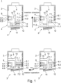
- Figures 1 and 2 show the trunking system corresponding to the first solution of the invention.
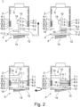
- the invention will be explained with reference to the busbar being configured as a first type busbar with respect to an attempt to mount a first type interconnecting member or a second type interconnecting member in figure 1 , and with reference to the busbar being configured as a second type busbar with respect to an attempt to mount a first type interconnecting member or a second type interconnecting member in figure 2 .
- the first type corresponds to a DC type configuration
- a second type corresponds to an AC type configuration.
- it will only be referred to the DC type or the AC type in order to distinguish between the different types of the busbar and the interconnecting member in its respective configurations.
- the trunking system 1 comprises a rail 2 which is usually made of steel or aluminum and provides a rigid structure which is mounted for example under a ceiling or to a wall and which provides sufficient mechanical strength in order to accommodate a busbar 2 and to carry one or a plurality of electrical components such as luminaires.
- the trunking comprises the rail 2 accommodating the busbar 5, wherein the busbar 5 is configured to support at least a first power supply wire 6.1 and a second power supply wire 6.2.
- the power supply wires 6.1 and 6.2 are inserted into grooves 7.1 and 7.2 thereby positioning the power supply wires 6.1 and 6.2 in the rail 2.
- Units comprising a rail 2 and a busbar 5 are state-of-the-art and used in a plurality of well-known trunking systems for lighting.
- an interconnecting member 3 is mounted in the trunking.
- the trunking comprises an opening 4 through which the interconnecting member 3 can be inserted such that an electrical contact between the power supply wires 6.1 and 6.2 and the electrical component can be established.
- a plurality of grooves 7.1, 7.2 and 7.3 building a first group of grooves are provided close to the right side wall of the rail 2.
- the first groove 7.1 and the second groove 7.2 are used for clamping the first power supply wire 6.1 and the second power supply wire 6.2.
- the first and second grooves 7.1 and 7.2 are arranged to sandwich a third groove 7.3.
- the third groove 7.3 is empty. Power is supplied via the interconnecting member 3 to an attached luminaire.
- the interconnecting member 3 in the DC type configuration provides a first electrical contact 11.1 and a second electrical contact 11.2 attached to a stem 10.
- the stem 10 carrying the first electrical contact 11.1 and the second electrical contact 11.2 is inserted through the opening 4 into the busbar 5 accommodated in the rail 2 in order to establish the electrical contact.
- the electrical contacts 11.1 and 11.2 extend towards the first group of grooves 7.1, 7.2 and 7.3 so that they project from the stem 10 in the same direction.
- the electrical contacts 11.1 and 11.2 lie within the same plane and have a distance from each other in the longitudinal direction of the stem 10 (corresponding to the insertion direction as indicated by the black arrow) that corresponds to the distance between the first groove 7.1 and the second groove 7.2 in the same direction.
- a projecting member 15 is fixed, which may be used in order to secure the interconnecting member 3 in the busbar and, thus, the rail 2.
- the busbar 5 may comprise additional grooves or other clamping elements or holding structures in order to provide additional functionality to the entire trunking system.
- a bus system might be included in the system enabling exchange of information between different components.
- the busbar 5 comprises a second group of grooves 8.1, 8.2 and 8.3. These grooves 8.1, 8.2 and 8.3 correspond in size and position to the grooves 7.1, 7.2 and 7.3.
- the groups of the first group and the grooves of the second group face each other such that the open sides of the grooves are directed towards each other.
- the DC type interconnecting member 3 is first inserted into an inside of the busbar 5 until a flange 12 comes into contact with a respective abutment surface 13 limiting the opening 4 in a lateral direction of the rail 2.
- the abutment surface 13 is provided on the rail 2 or the busbar 5.
- the abutment surface 13 limits a movement of both types of interconnecting members 3 into the inside of the busbar 5 and the rail 2 and defines the relative position of the electrical contacts 11.1 and 11.2 in the insertion direction relative to the power supply wires 6.1 and 6.2.
- a coding member 9 is selected from a plurality of coding members as it will be later explained with reference to figure 2 .
- the coding member as shown in figure 1 can be attached to the busbar 5 such that the rotational movement which is needed to establish a contact between the electrical contacts 11.1 and 11.2 with the power supply wires 6.1 and 6.2 is inhibited in case that an AC type interconnecting member 3 is inserted into the busbar 5.
- the coding member 9 configuring the busbar 5 as a DC type busbar 5 has a U-shape in cross action with the width between the two legs of the U-shape corresponding to the distance between the first groove 8.1 and the second groove 8.1 of the second group of grooves.
- the U-shaped coding element 9 blocks all three grooves 8.1, 8.2 and 8.3 such that no element can be introduced into these grooves. Consequently, in the configuration of the busbar 5 with the coding member 9, only the grooves of the first group are available.
- the DC type interconnecting member 3 is provided with a blocking member 16.
- the general structure of the stem 10 or the entire interconnecting member 3 enables that the electrical contacts 11.1 and 11.2 are arranged and fixed to the stem 10 in different positions and/or orientations. This characteristic can be used to additionally attach the blocking member 16 to the stem 10.
- the blocking element 16 is sandwiched between the electrical contacts 11.1 and 11.2, but its length exceeds the length of the electrical contacts 11.1 and 11.2.
- the blocking element 16 is made of a rigid material 16 so that, applying usual forces for mounting the interconnecting member 3 to the trunking, it will maintain its shape and position relative to the stem 10.
- the blocking element 16 is also rotated towards the third groove 7.3. Since the blocking element 16 is longer than the electrical contacts 11.1 and 11.2, the blocking element 16 needs to enter into the interior of the third groove 7.3.
- the third groove 7.3 is empty, which is the case for a busbar 5 in the DC -type configuration, this leads to the final mounting position as shown in the left lower part of figure 1 .
- the coding member 9 does not inhibit any operation of any of the involved components, and blocking element 16 may be freely moved since the third groove 7.3 is empty.
- the interconnecting member 3 is shown in its AC type configuration.
- the first electrical contact 11.1 and the second electrical contact 11.2 protrude in opposite directions from stem 10, because in an AC configuration the power supply wires "phase” and "neutral” are distributed over different sides of the busbar 5. This will be explained later with reference to figure 2 in more detail.
- the upper part shows the AC type connecting member 3 with the first electrical contact 11.1 and the second electrical contact 11.2 pointing to opposite directions from the stem 10 so that only one electrical contact, in the illustrated situation the first electrical contact 11.1, can get into contact with the first power supply wire 6.1 after the interconnecting member 3 is rotated towards its final position.
- This situation is shown in the lower part on the right side of figure 1 . It is to be noted, that the shown position cannot be reached, because the second electrical contact 11.2 collides with the coding member 9 before the interconnecting member 3 reaches its final position.
- the lateral extension of the coding member 9 in the busbar 5 significantly exceeds the depth of the grooves 8.1 and 8.2, for example at least twice the depth. This ensures an early contact between the second electrical contact 11.2 and the coding member 9.
- Such an early contact has the advantage that also the first electrical contact 11.1 is still far away from getting into contact with the first power supply wire 6.1.
- the AC type configuration of the busbar 5 is mainly defined by inserting a coding member into this empty groove 7.3 in order to inhibit that the blocking element 16 is introduced into the third groove 7.3.
- this coding element is formed by a third power supply wire 6.3.
- the configuration of the illustrated AC type busbar 5 provides three power supply wires 6.1, 6.2 and 6.3 held by the first group of grooves 7.1, 7.2 and 7.3. These three power supply wires 6.1, 6.2 and 6.3 are for example for providing a three-phase current.
- Corresponding neutral lines 18.1, 18.2 and 18.3 are inserted into the grooves 8.1, 8.2 and 8.3 of the second group of grooves on the other side of the busbar 5.
- the electrical contacts 11.1 and 11.2 pointing into opposing directions may come into contact with one of the three power supply wires 6.1, 6.2 and 6.3 and the corresponding neutral line 18.1, 18.2 or 80.3. Since no coding element 9 is present, the rotational movement is not inhibited and the AC type interconnecting member 3 can be brought into its final position, thereby establishing an electrical contact between the power supply and the electrical component attached to the interconnecting member 3.
- the DC type interconnecting member 3 On the other side, the DC type interconnecting member 3 has attached thereto, is explained already with reference to figure 1 , the blocking element 16. Since the third groove 7.3, in the AC - type configuration of the busbar 5, is no longer empty, it is not possible to move the blocking element 16 into the third groove 7.3. Thus, the rotational movement that is needed to bring the electrical contacts 11.1 and 11.2 of the DC type interconnecting member 3 into contact with the first power supply wire 6.1 and the second power supply wire 6.2 cannot be completed due to the collision of the blocking element 16 with the coding element, namely the third power supply wire 6.3. It is to be noted, that in case that no three-phase current shall be provided by the trunking, it is also possible to use any kind of material as coding member as long as the coding member can be inserted into the third groove 3.
- the present invention provides a simple way to configure, starting from a common basis, either an AC type busbar 5 or a DC type busbar 5 by attaching different coding elements 9 or 6.3 in different positions of the busbar 5 and further to attach a blocking element 16 to the interconnecting member 3 for configuring the interconnecting member 3 as DC type interconnecting member 3.
- the resulting structure allows only to mount an interconnecting member 3 into a busbar 5 of the same type. Thus, erroneous mounting of interconnecting members 3 is prevented while at the same time necessary logistics are significantly reduced.
- busbar and the interconnecting member are identical in both configurations and can be the same parts.
- the alternative solution uses a single coding member 19, which can be attached to the busbar 5 in order to configure the trunking as a DC type trunking.
- the mounted or attached coding member 19 reduces the maximum depth in the insertion direction of the interconnecting member 3.
- a DC type interconnecting member 3 is shown in a situation before it is inserted into the DC type busbar 5.
- the DC type interconnecting member 13 distinguishes from the one explained with reference to figures 1 and figure 2 in that no additional blocking element 16 is attached to the stem 10 of the DC type interconnecting member 3, and the flange 12 is reduced with respect to its lateral dimension.
- the lateral dimension which is the dimension in a direction perpendicular to the insertion direction and the longitudinal extension of the stem 10, corresponds to an opening width of the opening 4 of the rail 2.
- the insertion movement of the DC type interconnecting member 3 is not limited by an abutment of the flange 12 on the abutment surfaces 13 of the rail 2.
- a maximum insertion depth of the DC type interconnecting member 3 is defined by the position of the coding member 19. As it can be seen in the lower left part of figure 3 , the front end of the stem 10 at some point abuts the coding member 19 thereby limiting further insertion movement of the DC type interconnecting member 3.
- the locking mechanism including the compression spring 14 needs resistance limiting the insertion movement of the interconnecting member 3 such that compression of the compression spring 14 occurs by further movement of the operating handle.
- a rotation of the operating handle (not shown in the drawings) can be transferred to the flange 12 and, thus, the stem 10. So in case that the compression spring 14 is compressed due to the resistance provided by the coding member 19, the entire interconnecting member 3 can be rotated in order to bring the electrical contacts 11.1 and 11.2 into contact with the first power supply wire 6.1 and the second power supply wire 6.2, respectively.
- the length of the stem 10 is chosen to correspond to the distance between the abutment surface 13 of the rail 2 and the coding member 19. As shown in the schematic of figure 3 , this results in the flange 12 closing the opening in the rail 2.
- a coding member 19 which has basically an L shape, limits the maximum available insertion depth.
- the right part of figure 3 shows the situation when an AC type interconnecting member 3 is inserted and shall be mounted in the rail 2 and the busbar 5 of the DC type.
- the first electrical contact 11.1 and the second electrical contact 11.2 are arranged to project into opposite directions from the stem 10.
- a first abutment member 20 is attached to the front end of the stem 10 thereby increasing the overall length from the flange 12 to a surface of the first abutment member 20 facing the coding member 19.
- a second abutment member 21 is attached to the flange 12 in order to increase the lateral dimension of the flange 12 so that insertion of the AC type interconnecting member 3 is limited by abutment of the second abutment member 21 on the abutment surface 13 of the rail 2. This will be explained in greater detail with reference to figure 4 .
- the lower right side of figure 3 shows a situation in which an AC interconnecting member 3 is inserted into the rail 2 accommodating the DC type busbar 5 until the first abutment member 20 abuts the coding member 19.
- the position in the longitudinal direction corresponding to the insertion direction of the interconnecting member 3 of the first electrical contact 11.1 and the second electrical contact 11.2 does not correspond to the position of the grooves of the first group or the second group.
- no turning movement can be carried out which would bring the first electrical contact 11.1 in the illustrated embodiment into contact with the first power supply wire 6.1.
- the second electrical contact 11.2 collides with the sidewalls between the second and third grooves 8.2 and 8.3 of the second group of grooves.
- Figure 4 shows on the left side mounting of an AC type interconnecting member 3 into an AC type busbar 5. Absence of the coding member 19 characterizes the busbar 5 as an AC type busbar 5. The absence of the coding member 19 increases the maximum insertion depth and, thus, the AC type interconnecting member 3 can be inserted until the second abutment member 21 abuts the abutment surface 13 of rail 2. This situation is shown in the lower left part of figure 4 . Since now further insertion of the AC type interconnecting member 3 is inhibited, a further movement of the operating handle in the insertion direction will result in compression of the compression spring 14, which finally allows to operate the locking mechanism, thereby turning the AC type interconnecting member 3.
- the first electrical contact 11.1 and the second electrical contact 11.2 are automatically positioned such that the first electrical contact 11.1 comes into contact with the first power supply wire 6.1 and the second electrical contact 11.2 comes into contact with the respective neutral line 18.3.
- the first abutment member 20 is dimensioned such that, when the AC type interconnecting member 3 is inserted into an AC type busbar 5, it touches the ground of the AC type busbar 5 and operation of the locking mechanism is then possible.
- the resutling overall length of the first abutment member 20 and the stem 10 are set such that the first abutment member 20 will touch the ground of the rail when the interconnecting member 3 is fully inserted into the rail 2. Consequently, the locking operation can be performed.
- the second abutment member 21 is not necessary. However, it is also possible to provide the second abutment member 21 in addition.
- the right side of figure 4 shows the situation when a DC type interconnecting member 3 is tried to be mounted into an AC type busbar 5.
- a DC type interconnecting member 3 according to the second trunking system does not comprise any attached blocking elements or abutment members.
- the flange 12 has a lateral dimension that allows the flange 12 to penetrate through the opening 4.
- the present invention allows to use a plurality of common parts which are then configured to constitute a first trunking system configurable as a DC system or an AC system.
- the same plurality of parts can be configured to constitute a second trunking system configurable as a DC system or an AC system.
- the two configurable trunking systems differ in the structure of the components that need to be attached to configure the busbar and the interconnecting member as DC or AC type.
- interconnecting members of a certain type which can be produced by simple attachment of a blocking element (first system) or abutment members (second system)
- first system blocking element
- second system abutment members
- busbar configured to be of the same type by attaching a first coding member or a second coding member selected from a set of coding members (first trunking system) or by attaching or not attaching a single coding element (second trunking system).
Landscapes
- Connector Housings Or Holding Contact Members (AREA)
- Installation Of Bus-Bars (AREA)
Abstract
A configurable trunking system for use as a first type system or a second type system comprises a rail (2), a busbar (5), a set of at least two distinguishable coding members (9, 6.3) attachable to the busbar (5) to configure the busbar (5) as first type busbar or second type busbar, an interconnecting member (3) configurable as first type or second type interconnecting member, and a blocking member (16) attachable to the interconnecting member. The busbar (5) is configured to provide a support structure (7.1, 7.2, 7.3, 8.1, 8.2, 8.3) at least for two power supply wires (6.1, 6.2) and the coding members (9, 6.3), and the interconnecting member (3) is configured to be insertable into the rail (2) and busbar (5) for establishing electrical contact between the power supply wires (6.1, 6.2) and an electrical component attached to the interconnecting member (3). Electrical contacts (11.1, 11.2) are provided on the interconnecting member (3) in a first or a second arrangement to configure the interconnecting member (3) as first type interconnecting member or second type interconnecting member. The coding member (3) configuring the busbar (5) as first type busbar blocks an electrical contact (11.2) of the second type interconnecting member (3) and the coding member (6.3) configuring the busbar (5) as second type busbar blocks the blocking element (16) of the first type interconnecting member (3) for inhibiting establishment of the electrical contact.
Description
- The invention regards a configurable trunking system for lighting systems for use as a first type system or a second type system, in particular use in a DC system and alternatively in an AC system.
- Trunking systems in which power is supplied to electrical loads, in particular luminaires, are known in the art. Commonly known systems are exclusively operable with a certain, single energy providing system, for example, AC mains supply having 110 V or 230 V, or even three phase current with an AC voltage of 380 V. However, due to recent developments, it might be desirable to provide systems that can be supplied with direct voltage and current that is generated by a photovoltaics system or is provided by an energy storage system. Such systems may operate at for example 600 V to 800 V. So currently, a plurality of different systems components dedicated either for use in DC systems or for use in AC systems, which are not interchangeable and not compatible, are available in the market. However, this means complex logistics are necessary for manufacturing, distribution and even mounting such a plurality of different systems.
- It would therefore be desirable to provide a single trunking system, which has a common basis but may be configured to operate as an AC trunking system or as a DC trunking system. This is achieved by the proposed configurable trunking systems according to the independent claims.
- The central idea behind the present invention is that starting from commonly used basic components of the systems like a metal rail, in which a busbar is installed for carrying the power supply wires. It shall be possible by simple addition of certain elements or components to configure the system components, namely a trunking (compose of a rail/bus bar combination) and corresponding interconnecting members for use in a first type system or for use in a second type system. In order to facilitate understanding of the present invention, the first type system will be referred to as a DC system and the second type system will be referred to as an AC system.
- So in order to have a trunking system to be used in a DC system, all components need to be configured as DC -type components and it must be prevented that AC components can be inserted into a rail and busbar of the DC -type system in error and vice versa. With the present invention, it is now possible to attach coding members to the busbar, thereby configuring the busbar as a first type busbar or as a second type busbar depending on the attached coding member, and the busbar may then only be combined with an interconnecting member configured to be the same type interconnecting member. Configuration of the interconnecting member is correspondingly performed using attachable members.
- Generally, two equivalent approaches are considered according to the present invention, both using a coding member attachable to the busbar and corresponding attachable components (blocking elements or abutment members) attached to the interconnecting member for configuring the interconnecting member accordingly.
- The first approach comprises a set of at least two distinguishable coding members, with each of the coding members, when attached to the busbar, configuring the busbar to correspond to the first type or the second type. The second coding member can be a wire, which either acts as coding member or as power supply, depending on the configuration desired.
- The interconnecting member, which is intended to be inserted into the busbar (and thus the rail), in order to establish an electrical connection between power supply wires arranged in the busbar and an electrical load, for example a luminaire attached to and supported by the interconnecting member, must be configured to be of the same type. According to the first system of the invention, this is achieved by using a blocking member that is attachable to the interconnecting member. The blocking member enables to configure the interconnecting member as a first type interconnecting member or a second type interconnecting member, for example, by attaching the blocking member to the interconnecting member of the first type and not attaching the blocking member to an interconnecting member according to the second type.
- The coding members attached to the busbar in combination with the interconnecting member configured to be the first type interconnecting member or a second type interconnecting member enable only an interconnecting member of the first type to be mounted into a first type busbar such that the electrical contact between the power supply wires arranged in the first type busbar can be established by electrical contacts provided on the first type interconnecting member thereby providing electrical energy to the luminaire (or any other electrical load) attached to the first type interconnecting member. This is achieved by the coding member configuring the busbar as first type busbar blocking an electrical contact of the second type interconnecting member and the coding member configuring the busbar as second type busbar blocking the blocking element of the first type interconnecting member for inhibiting establishment of the electrical connection.
- It is to be noted that the process of "mounting" the interconnecting member consists of combined operation: first, the interconnecting member must be inserted into the rail in a straight forward direction rectangular to the longitudinal extension of the rail and bus bar. Once the necessary depth in the insertion direction is achieved, the electrical contacts attached to the interconnecting member are brought into contact with the power supply wires held in the busbar by a rotational movement of the interconnecting member. Such mounting procedure of the interconnecting members is known in the art and does not distinguish the invention from known systems. However, since the blocking member is attached to the interconnecting member of the first type, it is necessary that there is no obstacle in the trajectory of the blocking member when the first type interconnecting member shall be mounted into the first type busbar. Similarly, the electrical contacts of the second type interconnecting member can only come into contact with the power supply wires of the second type busbar in case that no obstacle blocks the movement of the electrical contacts when the rotational movement is performed in order to mount the interconnecting member in the busbar/rail.
- The present invention uses specific combinations of a coding member plus a blocking element to configure the busbar and interconnecting member to be used in a first type system and another coding member with no blocking element attached to the interconnecting member in order to configure the busbar and interconnecting member to be used in the second type system. The advantage of such a configuration is that a plurality of parts may be used for both systems, and at a very late stage of manufacturing it is possible to configure the resulting rail including the busbar, and the interconnecting member to belong to the first type or the second type thereby avoiding any possible wrong combination of the trunking (rail accommodating the busbar) and interconnecting member. So logistics for manufacturers are significantly simplified and, further, planners can rely on a single trunking system, which only needs to be configured as the first type system or the second type system without any other difference in characteristics like for example size or appearance.
- As it was explained above, the mounting of the interconnecting member in the trunking comprises two consecutive steps: first, the interconnecting member is moved inside the tail accommodating the busbar until a certain depth in the trunking is achieved before, second, a turning movement of a locking mechanism locks the interconnecting member in the rail/busbar and brings the electrical contacts into contact with the power supply wires provided in the busbar. The above explained first configurable system of the present invention takes advantage of the rotational movement at the end of the mounting process to inhibit mounting of the interconnecting member into a busbar/rail of the other system type. However, according to an alternative solution it is also possible to inhibit erroneous insertion of interconnecting members into wrong system busbars/rails using the insertion step:
- The configurable trunking system according to the second solution comprises, like the solution explained above, a rail and a busbar forming a trunking, and also an interconnecting member configurable for the first type system or the second type system. The second solution uses only a single coding member attachable to the busbar to configure the busbar as first type busbar. The interconnecting member comprises a locking mechanism that needs to be operated in order to perform the rotational movement as the second step of the mounting procedure. The system further comprises a first abutment member and a second abutment member attachable to the interconnecting member. The busbar is configured to provide a support structure at least for a two power supply wires and the coding member,
- The interconnecting member is configured to be mounted into the rail for establishing electrical contact between the power supply wires and an electrical component attached to the interconnecting member. Presence of the coding member in the busbar and the first abutment member attached to the interconnecting member inhibits operation of the locking mechanism, absence of the coding member and presence of the second abutment member allows operation of the locking mechanism, and absence of the coding member and absence of the second blocking member inhibits operation of the locking mechanism, wherein the locking operation establishes the electrical contact.
- Thus, contrary to the above explained first solution according to the invention, the rotational movement after insertion of the interconnecting member is inhibited by the locking mechanism itself. Contrary, in the first solution the locking mechanism may be operated but moving the electrical contacts and/or the blocking element in their final position needed to establish the electrical contact is inhibited.
- Advantageous solutions are defined in the dependent claims.
- The support structure of the busbar comprises a plurality of receiving grooves arranged in at least two groups with the open sides of the grooves of the first group facing the open sides of the grooves of the second group. Thus, it is possible to provide wiring on both sides of the busbar, but also to insert coding members on both sides of the busbar, depending on the desired type of busbar.
- The first group of grooves may comprise at least three grooves, and a first power supply wire and a second power supply wire arranged in grooves preferably sandwiching at least one further groove between them.
- The second group may comprise at least two grooves and the coding member configuring the busbar as first type busbar is U-shaped in cross-section with the legs of the U-shaped structure being insertable into these grooves of the second group.
- The interconnecting member preferably has a stem extending in the insertion direction and supporting at least a first electrical contact and a second electrical contact and further being configured to receive the attachable blocking member. Thus, it is possible to attach the blocking member to the stem of the interconnecting member. The advantage is therefore that the interconnecting members of the first type and the second type both can be configured starting with identical initial components. It is only distinguished between the first type interconnecting member and the second type interconnecting member because of the attachment of the blocking element and, in addition, the specific arrangement of the electrical contacts.
- In particular, the interconnecting member, in the first type configuration, may support the electrical contacts and the blocking element such that the electrical contacts and the blocking element project from the stem towards the same group of grooves, and the electrical contacts sandwich the blocking element. Having the configuration of the busbar with the power supply lines in grooves sandwiching an additional groove, it is therefore possible that the blocking element during the rotational movement enters the empty sandwiched groove, and the electrical contacts come into contact with the power supply wires. Thus, it is preferred that, contrary to elastic electrical contacts, the blocking element is rigid and therefore prevents the rotational movement bringing the interconnecting member into its end position in case that the blocking element cannot enter into the groove because of a coding member accommodated in the groove. It is particularly advantageous to insert a wire for power supply as coding member in the groove, which can then also be used for power supply in the DC type busbar.
- It is to be noted that it is also possible to have the power supply wires in adjacent grooves and an additional empty groove besides the two grooves carrying the power supply wires. In that case, the electrical contacts and the blocking member must be adapted with respect to their position so that the electrical contacts are attached to the stem of the interconnecting member at corresponding positions to the power supply wires. However, certain requirements regarding safety aspects may require a distance between the grooves carrying the power supply wires anyway and therefore it is preferred that the empty groove is sandwiched by the grooves supporting the power supply wires.
- The interconnecting member, in the second type configuration, supports the electrical contacts such one of the electrical contacts projects towards the first group of grooves and the other one of the electrical contacts projects towards the second group of grooves. When a turning movement of the second type interconnecting member shall be performed, one of the electrical contacts collides with the coding member attached to the busbar and configuring the busbar as a first type busbar, because in the first type busbar the power supply wires are arranged on one side of the busbar and the coding member is inserted into grooves on the opposite side of the busbar.
- The interconnecting member has a stem extending in the insertion direction, supporting at least a first electrical contact and second electrical contact and being configured to receive the first abutment member at its front end in the insertion direction. Thus, using such a first abutment member increases the overall length of the interconnecting member. In combination with the attached coding member limiting the depth that may be used for insertion of the interconnecting member, it becomes impossible to insert the interconnecting member with the first abutment member deep enough into the busbar so that the interconnecting member cannot be locked using the locking mechanism.
- The second abutment member is attachable to a flange carrying the stem at the stem's rear end with respect to the insertion direction. The second abutment member increases a lateral dimension of the flange with respect to the insertion direction of the interconnecting member. So specifically, the lateral dimension of the second abutment member increases the lateral extension of the flange such that it may not protrude any longer through an opening defined in the rail or in the busbar. Using the second abutment member being attached to the flange at the rear end of the stem limits the insertion depth in case that the coding member is not attached to the busbar and, thus, it is a busbar according to the second type.
- Preferably, a distance between a railside abutment surface of the rail or busbar and the coding member when attached to the busbar corresponds to the length from the front end to the rear end of the stem. Thus, correct insertion and mounting of the interconnecting member is only possible if no first abutment member is present in case that the coding member is attached to the busbar.
- The railside abutment surface has an opening wider than a lateral dimension of the flange but smaller than a lateral dimension of the second abutment member. This results are limiting the insertion depth of the interconnecting member with the attached second abutment member in case that no coding member is attached to the busbar.
- It is to be noted that in the present context "railside" is only used in order to define an element to belong to the rail or bus bar, which altogether build the trunking. As the skilled person will readily understand, it is also possible to provide the "railside abutment surface" at the busbar which is accommodated in the rail and commonly builds a unit into which the interconnecting members are inserted in order to mount for example a luminaire.
- Preferably, the locking mechanism is spring biased and is operable only when the spring is compressed, wherein compression of the spring is caused by a further movement of an operating handle in the insertion direction after an element of the interconnecting member already abuts a corresponding railside abutment surface. As the above given explanations already reveal, such a locking mechanism may advantageously be used in combination with the first and second abutment members, because a resistance in the insertion direction is needed which allows compressing the spring in order to initiate the rotational movement that brings the electrical contacts into contact with the power supply wires.
- Advantageous aspects and features of the present invention will now be explained with reference to the attached drawings in which
- Figure 1
- shows a first type trunking according to the first solution and its relation to a first type interconnecting member and a second interconnecting member,
- figure 2
- shows a second type trunking according to the first solution and its relation to the first type interconnecting member and a second type interconnecting member,
- figure 3
- shows a first type trunking according to the second solution and its relation to a first type interconnecting member and a second interconnecting member, and
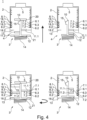
- figure 4
- shows a second type trunking according to the second solution and its relation to a first type interconnecting member and a second interconnecting member.
-
Figures 1 and2 show the trunking system corresponding to the first solution of the invention. The invention will be explained with reference to the busbar being configured as a first type busbar with respect to an attempt to mount a first type interconnecting member or a second type interconnecting member infigure 1 , and with reference to the busbar being configured as a second type busbar with respect to an attempt to mount a first type interconnecting member or a second type interconnecting member infigure 2 . As explained above, the first type corresponds to a DC type configuration and a second type corresponds to an AC type configuration. In the following for facilitating understanding of the present invention, it will only be referred to the DC type or the AC type in order to distinguish between the different types of the busbar and the interconnecting member in its respective configurations. - Coming now to
figure 1 , at first the configuration of the trunking oftrunking system 1 will be explained. Thetrunking system 1 comprises arail 2 which is usually made of steel or aluminum and provides a rigid structure which is mounted for example under a ceiling or to a wall and which provides sufficient mechanical strength in order to accommodate abusbar 2 and to carry one or a plurality of electrical components such as luminaires. - In the illustrated embodiment, the trunking comprises the
rail 2 accommodating thebusbar 5, wherein thebusbar 5 is configured to support at least a first power supply wire 6.1 and a second power supply wire 6.2. The power supply wires 6.1 and 6.2 are inserted into grooves 7.1 and 7.2 thereby positioning the power supply wires 6.1 and 6.2 in therail 2. Units comprising arail 2 and abusbar 5 are state-of-the-art and used in a plurality of well-known trunking systems for lighting. - In order to provide an electrical load, such as a luminaire, with electrical power, an interconnecting
member 3 is mounted in the trunking. The trunking comprises anopening 4 through which the interconnectingmember 3 can be inserted such that an electrical contact between the power supply wires 6.1 and 6.2 and the electrical component can be established. - It is to be noted that all the figures attached and used for explanation of the present invention only show cross sections of an elongated structure of the
rail 2, thebusbar 5, and components attached thereto. - In the illustrated embodiment of the
busbar 5, a plurality of grooves 7.1, 7.2 and 7.3 building a first group of grooves are provided close to the right side wall of therail 2. The first groove 7.1 and the second groove 7.2 are used for clamping the first power supply wire 6.1 and the second power supply wire 6.2. The first and second grooves 7.1 and 7.2 are arranged to sandwich a third groove 7.3. In the DC configuration of thebusbar 5, the third groove 7.3 is empty. Power is supplied via the interconnectingmember 3 to an attached luminaire. - The interconnecting
member 3 in the DC type configuration provides a first electrical contact 11.1 and a second electrical contact 11.2 attached to astem 10. Thestem 10 carrying the first electrical contact 11.1 and the second electrical contact 11.2 is inserted through theopening 4 into thebusbar 5 accommodated in therail 2 in order to establish the electrical contact. - The situation shown in the upper left part of
figure 1 shows a DCtype interconnecting member 3 during the process of inserting it into thebusbar 5 as it is indicated by the thick black arrow. - The electrical contacts 11.1 and 11.2 extend towards the first group of grooves 7.1, 7.2 and 7.3 so that they project from the
stem 10 in the same direction. Thus, the electrical contacts 11.1 and 11.2 lie within the same plane and have a distance from each other in the longitudinal direction of the stem 10 (corresponding to the insertion direction as indicated by the black arrow) that corresponds to the distance between the first groove 7.1 and the second groove 7.2 in the same direction. Close to the front end of thestem 10, which is the end pointing in the insertion direction of the interconnectingmember 3, a projectingmember 15 is fixed, which may be used in order to secure the interconnectingmember 3 in the busbar and, thus, therail 2. - It is to be noted that in addition to the grooves mentioned herein and explained with reference to their meaning for the present invention, the
busbar 5 may comprise additional grooves or other clamping elements or holding structures in order to provide additional functionality to the entire trunking system. For example, a bus system might be included in the system enabling exchange of information between different components. - Close to the opposing side (left) wall of the
rail 2, thebusbar 5 comprises a second group of grooves 8.1, 8.2 and 8.3. These grooves 8.1, 8.2 and 8.3 correspond in size and position to the grooves 7.1, 7.2 and 7.3. The groups of the first group and the grooves of the second group face each other such that the open sides of the grooves are directed towards each other. - In order to establish an electrical connection between the power supply wires 6.1 and 6.2 the DC
type interconnecting member 3 is first inserted into an inside of thebusbar 5 until aflange 12 comes into contact with arespective abutment surface 13 limiting theopening 4 in a lateral direction of therail 2. Theabutment surface 13 is provided on therail 2 or thebusbar 5. Theabutment surface 13 limits a movement of both types of interconnectingmembers 3 into the inside of thebusbar 5 and therail 2 and defines the relative position of the electrical contacts 11.1 and 11.2 in the insertion direction relative to the power supply wires 6.1 and 6.2. Once theflange 12 made contact with theabutment surface 13, no further movement of theflange 12 and thestem 10 attached to theflange 12 is possible. However, an operating handle (not shown in the drawing) and theflange 12 sandwich acompression spring 14, which is part of a locking mechanism. It is to be noted that reference to the locking mechanism is only made by thespring 14 shown in the drawing. However, such locking mechanisms are generally known in the art and provide the following function: after theflange 12 abuts theabutment surface 13, a further movement of the operating handle compresses thecompression spring 14, and once thecompression spring 14 is compressed, a rotation of the entire interconnectingmember 3 is enabled. - The situation after operating the locking mechanism is shown in the lower part on the left side of
figure 1 . Here it can be recognized that thespring 14 is compressed and the electrical contacts 11.1 and 11.2 as well as a fixingmember 15 are thus rotated sideways while in the upper part of the drawing, these elements were only visible partly due to the perspective in the illustration. In the lower part on the left side offigure 1 , it can be seen that the electrical contacts 11.1 and 11.2 contact the power supply wires 6.1 and 6.2, respectively. Thus, an electrical connection can be established to provide an attached luminaire (not shown) with electrical power. - The components explained so far a commonly known for trunking systems according to the state-of-the-art. However, according to the present invention (first solution), a
coding member 9 is selected from a plurality of coding members as it will be later explained with reference tofigure 2 . The coding member as shown infigure 1 can be attached to thebusbar 5 such that the rotational movement which is needed to establish a contact between the electrical contacts 11.1 and 11.2 with the power supply wires 6.1 and 6.2 is inhibited in case that an ACtype interconnecting member 3 is inserted into thebusbar 5. - The
coding member 9 configuring thebusbar 5 as aDC type busbar 5 has a U-shape in cross action with the width between the two legs of the U-shape corresponding to the distance between the first groove 8.1 and the second groove 8.1 of the second group of grooves. Thus, theU-shaped coding element 9 blocks all three grooves 8.1, 8.2 and 8.3 such that no element can be introduced into these grooves. Consequently, in the configuration of thebusbar 5 with thecoding member 9, only the grooves of the first group are available. - In addition to the first electrical contact 11.1 and the second electrical contact 11.2, the DC
type interconnecting member 3 is provided with a blockingmember 16. It is to be noted that the general structure of thestem 10 or the entire interconnectingmember 3 enables that the electrical contacts 11.1 and 11.2 are arranged and fixed to thestem 10 in different positions and/or orientations. This characteristic can be used to additionally attach the blockingmember 16 to thestem 10. As it can be seen from the upper left part and the lower left part offigure 1 , the blockingelement 16 is sandwiched between the electrical contacts 11.1 and 11.2, but its length exceeds the length of the electrical contacts 11.1 and 11.2. Further, the blockingelement 16 is made of arigid material 16 so that, applying usual forces for mounting the interconnectingmember 3 to the trunking, it will maintain its shape and position relative to thestem 10. Thus, when rotating the interconnectingmember 3 such that the electrical contacts 11.1 and 11.2 come into contact with the power supply wires 6.1 and 6.2, the blockingelement 16 is also rotated towards the third groove 7.3. Since the blockingelement 16 is longer than the electrical contacts 11.1 and 11.2, the blockingelement 16 needs to enter into the interior of the third groove 7.3. In case that the third groove 7.3 is empty, which is the case for abusbar 5 in the DC -type configuration, this leads to the final mounting position as shown in the left lower part offigure 1 . It is to be noted that thecoding member 9 does not inhibit any operation of any of the involved components, and blockingelement 16 may be freely moved since the third groove 7.3 is empty. - Starting again from the trunking in the DC type configuration shown in
figure 1 , it is now referred to the right upper part and lower right part offigure 1 . Here, the interconnectingmember 3 is shown in its AC type configuration. The first electrical contact 11.1 and the second electrical contact 11.2 protrude in opposite directions fromstem 10, because in an AC configuration the power supply wires "phase" and "neutral" are distributed over different sides of thebusbar 5. This will be explained later with reference tofigure 2 in more detail. - The upper part shows the AC
type connecting member 3 with the first electrical contact 11.1 and the second electrical contact 11.2 pointing to opposite directions from thestem 10 so that only one electrical contact, in the illustrated situation the first electrical contact 11.1, can get into contact with the first power supply wire 6.1 after the interconnectingmember 3 is rotated towards its final position. This situation is shown in the lower part on the right side offigure 1 . It is to be noted, that the shown position cannot be reached, because the second electrical contact 11.2 collides with thecoding member 9 before the interconnectingmember 3 reaches its final position. In order to early inhibit further rotating movement of the interconnectingmember 3, it is preferred that the lateral extension of thecoding member 9 in the busbar 5 (corresponding to the height of the U-shape) significantly exceeds the depth of the grooves 8.1 and 8.2, for example at least twice the depth. This ensures an early contact between the second electrical contact 11.2 and thecoding member 9. Such an early contact has the advantage that also the first electrical contact 11.1 is still far away from getting into contact with the first power supply wire 6.1. - The explanations given with respect to
figure 1 illustrate the situation with a DC type configuration of the trunking (or to be more precise of thebusbar 5 accommodated in the rail 2) when trying to mount a DCtype interconnecting member 3 or an ACtype interconnecting member 3. With respect tofigure 2 and attempt to mount a DCtype interconnecting member 3 or an ACtype interconnecting member 3 into anAC type busbar 5 will be explained. - First, the difference between the
DC type busbar 5 and theAC type busbar 5 will be explained. In the DC type configuration of thebusbar 5, only the first power supply wire 6.1 and the second power supply wire 6.2 were inserted into the first groove 7.1 and the second groove 7.2, respectively. The third groove 7.3 was left empty so that the blockingelement 16 could be inserted into the empty groove 7.3. - The AC type configuration of the
busbar 5 is mainly defined by inserting a coding member into this empty groove 7.3 in order to inhibit that the blockingelement 16 is introduced into the third groove 7.3. In the illustrated embodiment, this coding element is formed by a third power supply wire 6.3. The configuration of the illustratedAC type busbar 5 provides three power supply wires 6.1, 6.2 and 6.3 held by the first group of grooves 7.1, 7.2 and 7.3. These three power supply wires 6.1, 6.2 and 6.3 are for example for providing a three-phase current. Corresponding neutral lines 18.1, 18.2 and 18.3 are inserted into the grooves 8.1, 8.2 and 8.3 of the second group of grooves on the other side of thebusbar 5. - As shown in the lower part on the left side of
figure 2 , the electrical contacts 11.1 and 11.2 pointing into opposing directions may come into contact with one of the three power supply wires 6.1, 6.2 and 6.3 and the corresponding neutral line 18.1, 18.2 or 80.3. Since nocoding element 9 is present, the rotational movement is not inhibited and the ACtype interconnecting member 3 can be brought into its final position, thereby establishing an electrical contact between the power supply and the electrical component attached to the interconnectingmember 3. - On the other side, the DC
type interconnecting member 3 has attached thereto, is explained already with reference tofigure 1 , the blockingelement 16. Since the third groove 7.3, in the AC - type configuration of thebusbar 5, is no longer empty, it is not possible to move the blockingelement 16 into the third groove 7.3. Thus, the rotational movement that is needed to bring the electrical contacts 11.1 and 11.2 of the DCtype interconnecting member 3 into contact with the first power supply wire 6.1 and the second power supply wire 6.2 cannot be completed due to the collision of the blockingelement 16 with the coding element, namely the third power supply wire 6.3. It is to be noted, that in case that no three-phase current shall be provided by the trunking, it is also possible to use any kind of material as coding member as long as the coding member can be inserted into thethird groove 3. - As the above given explanations clearly show, the present invention provides a simple way to configure, starting from a common basis, either an
AC type busbar 5 or aDC type busbar 5 by attachingdifferent coding elements 9 or 6.3 in different positions of thebusbar 5 and further to attach a blockingelement 16 to the interconnectingmember 3 for configuring the interconnectingmember 3 as DCtype interconnecting member 3. The resulting structure allows only to mount an interconnectingmember 3 into abusbar 5 of the same type. Thus, erroneous mounting of interconnectingmembers 3 is prevented while at the same time necessary logistics are significantly reduced. - The shapes of the busbar and the interconnecting member are identical in both configurations and can be the same parts.
- An alternative composition also using a coding member in order to configure the
busbar 5 as aDC type busbar 5 will be explained now with reference tofigures 3 andfigure 4 . - As far as the above given explanations are still valid with respect to components of the trunking or the interconnecting
member 3, repetitive explanation thereof is omitted. - The alternative solution uses a
single coding member 19, which can be attached to thebusbar 5 in order to configure the trunking as a DC type trunking. As it can be seen infigure 3 , the mounted or attached codingmember 19 reduces the maximum depth in the insertion direction of the interconnectingmember 3. On the upper left side offigure 3 , a DCtype interconnecting member 3 is shown in a situation before it is inserted into theDC type busbar 5. - The DC
type interconnecting member 13 distinguishes from the one explained with reference tofigures 1 andfigure 2 in that no additional blockingelement 16 is attached to thestem 10 of the DCtype interconnecting member 3, and theflange 12 is reduced with respect to its lateral dimension. Specifically, the lateral dimension, which is the dimension in a direction perpendicular to the insertion direction and the longitudinal extension of thestem 10, corresponds to an opening width of theopening 4 of therail 2. Thus, the insertion movement of the DCtype interconnecting member 3 is not limited by an abutment of theflange 12 on the abutment surfaces 13 of therail 2. However, a maximum insertion depth of the DCtype interconnecting member 3 is defined by the position of thecoding member 19. As it can be seen in the lower left part offigure 3 , the front end of thestem 10 at some point abuts the codingmember 19 thereby limiting further insertion movement of the DCtype interconnecting member 3. - As explained above, the locking mechanism including the
compression spring 14 needs resistance limiting the insertion movement of the interconnectingmember 3 such that compression of thecompression spring 14 occurs by further movement of the operating handle. When thecompression spring 14 is compressed, a rotation of the operating handle (not shown in the drawings) can be transferred to theflange 12 and, thus, thestem 10. So in case that thecompression spring 14 is compressed due to the resistance provided by the codingmember 19, the entire interconnectingmember 3 can be rotated in order to bring the electrical contacts 11.1 and 11.2 into contact with the first power supply wire 6.1 and the second power supply wire 6.2, respectively. - Preferably, the length of the
stem 10 is chosen to correspond to the distance between theabutment surface 13 of therail 2 and thecoding member 19. As shown in the schematic offigure 3 , this results in theflange 12 closing the opening in therail 2. - So for the second solution, a
coding member 19, which has basically an L shape, limits the maximum available insertion depth. - The right part of
figure 3 shows the situation when an ACtype interconnecting member 3 is inserted and shall be mounted in therail 2 and thebusbar 5 of the DC type. Again, the first electrical contact 11.1 and the second electrical contact 11.2 are arranged to project into opposite directions from thestem 10. Afirst abutment member 20 is attached to the front end of thestem 10 thereby increasing the overall length from theflange 12 to a surface of thefirst abutment member 20 facing the codingmember 19. - A
second abutment member 21 is attached to theflange 12 in order to increase the lateral dimension of theflange 12 so that insertion of the ACtype interconnecting member 3 is limited by abutment of thesecond abutment member 21 on theabutment surface 13 of therail 2. This will be explained in greater detail with reference tofigure 4 . - The lower right side of
figure 3 shows a situation in which anAC interconnecting member 3 is inserted into therail 2 accommodating theDC type busbar 5 until thefirst abutment member 20 abuts the codingmember 19. In this situation, the position in the longitudinal direction corresponding to the insertion direction of the interconnectingmember 3 of the first electrical contact 11.1 and the second electrical contact 11.2 does not correspond to the position of the grooves of the first group or the second group. Thus, no turning movement can be carried out which would bring the first electrical contact 11.1 in the illustrated embodiment into contact with the first power supply wire 6.1. Further, also the second electrical contact 11.2 collides with the sidewalls between the second and third grooves 8.2 and 8.3 of the second group of grooves. In case that the projectingmember 15 is positioned as shown infigure 3 , the same is correct for a collision of the projectingmember 15 and a sidewall of the groove 8.1. Thus, the inserted ACtype interconnecting member 3 cannot be rotated into its final position. As it can be seen, thesecond abutment member 21 cannot be brought into contact with the abutment surface of therail 2. -
Figure 4 shows on the left side mounting of an ACtype interconnecting member 3 into anAC type busbar 5. Absence of thecoding member 19 characterizes thebusbar 5 as anAC type busbar 5. The absence of thecoding member 19 increases the maximum insertion depth and, thus, the ACtype interconnecting member 3 can be inserted until thesecond abutment member 21 abuts theabutment surface 13 ofrail 2. This situation is shown in the lower left part offigure 4 . Since now further insertion of the ACtype interconnecting member 3 is inhibited, a further movement of the operating handle in the insertion direction will result in compression of thecompression spring 14, which finally allows to operate the locking mechanism, thereby turning the ACtype interconnecting member 3. Since the insertion depth is now defined by thesecond abutment member 21, the first electrical contact 11.1 and the second electrical contact 11.2 are automatically positioned such that the first electrical contact 11.1 comes into contact with the first power supply wire 6.1 and the second electrical contact 11.2 comes into contact with the respective neutral line 18.3. - Alternatively, the
first abutment member 20 is dimensioned such that, when the ACtype interconnecting member 3 is inserted into anAC type busbar 5, it touches the ground of theAC type busbar 5 and operation of the locking mechanism is then possible. The resutling overall length of thefirst abutment member 20 and thestem 10 are set such that thefirst abutment member 20 will touch the ground of the rail when the interconnectingmember 3 is fully inserted into therail 2. Consequently, the locking operation can be performed. In such a configuration, thesecond abutment member 21 is not necessary. However, it is also possible to provide thesecond abutment member 21 in addition. - The right side of
figure 4 shows the situation when a DCtype interconnecting member 3 is tried to be mounted into anAC type busbar 5. A DCtype interconnecting member 3 according to the second trunking system does not comprise any attached blocking elements or abutment members. Thus, theflange 12 has a lateral dimension that allows theflange 12 to penetrate through theopening 4. When the DCtype interconnecting member 3 is moved into the insertion direction, no resistance is available for blocking further movement of thestem 10 or theflange 12. Since no resistance is available, thecompression spring 14 will not be compressed and as a result thereof, no rotation operation can be transferred from the operating handle to the DCtype interconnecting member 3 and the situation as shown in the lower right part offigure 4 will occur. The electrical contacts 11.1 and 11.2 cannot be rotated by operation of the locking mechanism towards the power supply wires 6.1 and 6.2. - To sum up, the present invention allows to use a plurality of common parts which are then configured to constitute a first trunking system configurable as a DC system or an AC system. Alternatively, the same plurality of parts can be configured to constitute a second trunking system configurable as a DC system or an AC system. The two configurable trunking systems differ in the structure of the components that need to be attached to configure the busbar and the interconnecting member as DC or AC type. Common to both systems is that interconnecting members of a certain type, which can be produced by simple attachment of a blocking element (first system) or abutment members (second system), can only be inserted into a busbar configured to be of the same type by attaching a first coding member or a second coding member selected from a set of coding members (first trunking system) or by attaching or not attaching a single coding element (second trunking system).
Claims (14)
- Configurable trunking system for use as a first type system or a second type system,the trunking system comprising a rail (2), a busbar (5), a set of at least two distinguishable coding members (9, 6.3) attachable to the busbar (5) to configure the busbar (5) as first type busbar or second type busbar, an interconnecting member (3) configurable as first type or second type interconnecting member, and a blocking member (16) attachable to the interconnecting member, whereinthe busbar (5) is configured to provide a support structure (7.1, 7.2, 7.3, 8.1, 8.2, 8.3) at least for two power supply wires (6.1, 6.2) and the coding members (9, 6.3),the interconnecting member (3) is configured to be insertable into the rail (2) and busbar (5) for establishing electrical contact between the power supply wires (6.1, 6.2) and an electrical component attached to the interconnecting member (3), and electrical contacts (11.1, 11.2) are provided on the interconnecting member (3) in a first or a second arrangement to configure the interconnecting member (3) as first type interconnecting member or second type interconnecting member,and wherein the coding member (3) configuring the busbar (5) as first type busbar blocks an electrical contact (11.2) of the second type interconnecting member (3) and the coding member (6.3) configuring the busbar (5) as second type busbar blocks the blocking element (16) of the first type interconnecting member (3) for inhibiting establishment of the electrical contact.
- Configurable trunking system according to claim 1,
wherein the support structure of the busbar comprises a plurality of receiving grooves arranged in at least two groups with the open sides of the grooves of the first group facing the open side of the grooves of the second group. - Configurable trunking system according to claim 2,
wherein the first group comprises at least three grooves (7.1, 7.2, 7.3) and a first power supply wire (6.1, 6.2) and a second power supply wire are arranged in grooves (7.1, 7.2) sandwiching at least one further groove (7.34) between them. - Configurable trunking system according to claim 2 or 3,
wherein the second group comprises at least two grooves (8.1, 8.2, 8.3) and the coding member (9) configuring the busbar (5) as first type busbar is U-shaped in cross-section with the legs of the U-shaped structure being insertable into the grooves (8.1, 8.2, 8.3) of the second group. - Configurable trunking system according to any one of the preceding claims,
wherein the interconnecting member (3) has a stem (10) extending in the insertion direction and supporting at least a first electrical contact (11.1) and a second electrical contact (11.2) and further being configured to receive the attachable blocking member (16). - Configurable trunking system according to claim 5,
wherein the interconnecting member (3), in the first type configuration, supports the electrical contacts (11.1, 11.2) and the blocking element (16) such that the electrical contacts (11.1, 11.2) and the blocking element (16) project from the stem (10) towards the same group of grooves, and the electrical contacts (11.1, 11.2) sandwich the blocking element (16). - Configurable trunking system according to claim 5 or 6,
wherein the interconnecting member (3), in the second type configuration, supports the electrical contacts (11.1, 11.2) such one of the electrical contacts (11.1, 11.2) projects towards the first group of grooves and the other one of the electrical contacts (11.1, 11.2) projects towards the second group of grooves. - Configurable trunking system for use as a first type system or a second type system,the trunking system comprising a rail (2), a busbar (5), a coding member (19) attachable to the busbar (5) to configure the busbar (5) as first type busbar, an interconnecting member (3) comprising a locking mechanism, and a first abutment member (20) and a second abutment member (21) attachable to the interconnecting member (3),
whereinthe busbar (5) is configured to provide a support structure (7.1, 7.2, 7.3, 8.1, 8.2, 8.3) at least for a two power supply wires (6.1, 6.2) and the coding member (19),the interconnecting member (3) is configured to be insertable into the rail (2) for establishing electrical contact between the power supply wires (6.1, .6.2) and an electrical component attached to the interconnecting member (3), and electrical contacts (11., 11.2) are provided on the interconnecting member (3) in a first arrangement or a second arrangement to configure the interconnecting member (3) as first type interconnecting member or a second type interconnecting member,and presence of the coding member (19) and the first abutment member (20) inhibits operation of the locking mechanism, absence of the coding member (19) and presence of the second abutment member (21) allows operation of the locking mechanism, and absence of the coding member (19) and absence of the second abutment member (21) inhibits operation of the locking mechanism, wherein the locking operation establishes the electrical contact. - Configurable trunking system according to claim 8,
wherein the interconnecting member (3) has a stem (10) extending in the insertion direction, supporting at least a first electrical contact (11.1) and second electrical contact (11.2) and being configured to receive the first abutment member (20) at its front end in the insertion direction. - Configurable trunking system according to claim 7 or 8,
wherein the second abutment member (21) is attachable to a flange (12) carrying the stem (10) at the stem's rear end with respect to the insertion direction and increases a lateral dimension of the flange (12) with respect to the insertion direction of the interconnecting member (3). - Configurable trunking system according to claim 9 or 10,
wherein a distance between a railside abutment surface (13) and the coding member (19) corresponds to the length from the front end to the rear end of the stem (10). - Configurable trunking system according to claim 11,
wherein the railside abutment surface (13) has an opening (4) wider than a lateral dimension of the flange (12) but smaller than a lateral dimension of the second abutment member (21). - Configurable trunking system according to claims 8,
wherein the first abutment member (20) is dimensioned such that resulting length of the stem (10) and the first abutment member (20) is equal to distance from the flange (12) to enable operation locking operation. - Configurable trunking system according to any one of claims 8 to 13,
wherein the locking mechanism is spring biased and is operable only when the spring (14) is compressed, wherein compression of the spring (14) is caused by an insertion movement of the interconnecting member (3) by an operating handle of the interconnecting member (3).
Priority Applications (3)
| Application Number | Priority Date | Filing Date | Title |
|---|---|---|---|
| EP23155485.8A EP4415186A1 (en) | 2023-02-08 | 2023-02-08 | Configurable trunking system for lighting systems |
| CN202480011304.XA CN120660246A (en) | 2023-02-08 | 2024-01-17 | Configurable cluster system |
| PCT/EP2024/051068 WO2024165288A1 (en) | 2023-02-08 | 2024-01-17 | Configurable trunking system |
Applications Claiming Priority (1)
| Application Number | Priority Date | Filing Date | Title |
|---|---|---|---|
| EP23155485.8A EP4415186A1 (en) | 2023-02-08 | 2023-02-08 | Configurable trunking system for lighting systems |
Publications (1)
| Publication Number | Publication Date |
|---|---|
| EP4415186A1 true EP4415186A1 (en) | 2024-08-14 |
Family
ID=85202152
Family Applications (1)
| Application Number | Title | Priority Date | Filing Date |
|---|---|---|---|
| EP23155485.8A Pending EP4415186A1 (en) | 2023-02-08 | 2023-02-08 | Configurable trunking system for lighting systems |
Country Status (3)
| Country | Link |
|---|---|
| EP (1) | EP4415186A1 (en) |
| CN (1) | CN120660246A (en) |
| WO (1) | WO2024165288A1 (en) |
Cited By (1)
| Publication number | Priority date | Publication date | Assignee | Title |
|---|---|---|---|---|
| WO2026077693A1 (en) * | 2024-10-09 | 2026-04-16 | Zumtobel Lighting Gmbh | Mounting rail for luminaires or electrical units |
Citations (2)
| Publication number | Priority date | Publication date | Assignee | Title |
|---|---|---|---|---|
| GB2005490A (en) * | 1977-09-30 | 1979-04-19 | Kokvik B O | Adapter plug for current supply rail systems |
| US20070015388A1 (en) * | 2005-04-26 | 2007-01-18 | Erco Leuchten Gmbh | Power-rail adapter and power rail |
-
2023
- 2023-02-08 EP EP23155485.8A patent/EP4415186A1/en active Pending
-
2024
- 2024-01-17 CN CN202480011304.XA patent/CN120660246A/en active Pending
- 2024-01-17 WO PCT/EP2024/051068 patent/WO2024165288A1/en not_active Ceased
Patent Citations (2)
| Publication number | Priority date | Publication date | Assignee | Title |
|---|---|---|---|---|
| GB2005490A (en) * | 1977-09-30 | 1979-04-19 | Kokvik B O | Adapter plug for current supply rail systems |
| US20070015388A1 (en) * | 2005-04-26 | 2007-01-18 | Erco Leuchten Gmbh | Power-rail adapter and power rail |
Cited By (1)
| Publication number | Priority date | Publication date | Assignee | Title |
|---|---|---|---|---|
| WO2026077693A1 (en) * | 2024-10-09 | 2026-04-16 | Zumtobel Lighting Gmbh | Mounting rail for luminaires or electrical units |
Also Published As
| Publication number | Publication date |
|---|---|
| WO2024165288A1 (en) | 2024-08-15 |
| CN120660246A (en) | 2025-09-16 |
Similar Documents
| Publication | Publication Date | Title |
|---|---|---|
| ES2589959T3 (en) | Adapter device for a low voltage switching device | |
| US10879642B2 (en) | Busbar system | |
| US7104832B2 (en) | Modular electrical connector and method of using | |
| US3603918A (en) | Electric power distribution system | |
| CA2893900C (en) | Power data housing | |
| EP2369702B1 (en) | Plug interlock device for vacuum circuit breaker | |
| HU201850B (en) | Channel of rail conductor with connecting device | |
| WO2024165288A1 (en) | Configurable trunking system | |
| US5876224A (en) | Bus bar adaptor | |
| MX2007012281A (en) | Multiple circuit receptacles. | |
| US6616465B1 (en) | Bus bar for electrical power distribution | |
| CA2263639A1 (en) | Upgradable functional feeder unit of a low-voltage electrical cubicle | |
| US20010012194A1 (en) | Plug-in draw out unit | |
| KR101638043B1 (en) | Lever actuated electrical center assembly | |
| US7446635B2 (en) | Combination of two electromagnetic switching devices | |
| KR102246825B1 (en) | Connecting Clip and MCC with the same | |
| JPS639344B2 (en) | ||
| US4550231A (en) | Trolley rail | |
| HU218400B (en) | Leakage current module that can be assembled with circuit breakers | |
| CN221928914U (en) | Vertical distribution busbar assembly and distribution cabinet | |
| KR102756583B1 (en) | Busduct branching box and busduct system having the same | |
| US12620785B2 (en) | Plug-in socket system | |
| EP3767766B1 (en) | Electric or electronic device | |
| CN223942365U (en) | Sliding contact type bus duct with T-shaped conducting bars | |
| JP2005065397A (en) | Busbar structure for connection between disconnectors |
Legal Events
| Date | Code | Title | Description |
|---|---|---|---|
| PUAI | Public reference made under article 153(3) epc to a published international application that has entered the european phase |
Free format text: ORIGINAL CODE: 0009012 |
|
| STAA | Information on the status of an ep patent application or granted ep patent |
Free format text: STATUS: THE APPLICATION HAS BEEN PUBLISHED |
|
| AK | Designated contracting states |
Kind code of ref document: A1 Designated state(s): AL AT BE BG CH CY CZ DE DK EE ES FI FR GB GR HR HU IE IS IT LI LT LU LV MC ME MK MT NL NO PL PT RO RS SE SI SK SM TR |
|
| STAA | Information on the status of an ep patent application or granted ep patent |
Free format text: STATUS: REQUEST FOR EXAMINATION WAS MADE |
|
| 17P | Request for examination filed |
Effective date: 20250204 |