EP4415134A1 - End cover assembly, energy storage apparatus, and electricity-consumption device - Google Patents
End cover assembly, energy storage apparatus, and electricity-consumption device Download PDFInfo
- Publication number
- EP4415134A1 EP4415134A1 EP23218192.5A EP23218192A EP4415134A1 EP 4415134 A1 EP4415134 A1 EP 4415134A1 EP 23218192 A EP23218192 A EP 23218192A EP 4415134 A1 EP4415134 A1 EP 4415134A1
- Authority
- EP
- European Patent Office
- Prior art keywords
- flow passage
- plastic member
- lower plastic
- hollow hole
- sealing portion
- Prior art date
- Legal status (The legal status is an assumption and is not a legal conclusion. Google has not performed a legal analysis and makes no representation as to the accuracy of the status listed.)
- Granted
Links
Images

Classifications
-
- H—ELECTRICITY
- H01—ELECTRIC ELEMENTS
- H01M—PROCESSES OR MEANS, e.g. BATTERIES, FOR THE DIRECT CONVERSION OF CHEMICAL ENERGY INTO ELECTRICAL ENERGY
- H01M50/00—Constructional details or processes of manufacture of the non-active parts of electrochemical cells other than fuel cells, e.g. hybrid cells
- H01M50/10—Primary casings; Jackets or wrappings
- H01M50/183—Sealing members
- H01M50/186—Sealing members characterised by the disposition of the sealing members
- H01M50/188—Sealing members characterised by the disposition of the sealing members the sealing members being arranged between the lid and terminal
-
- H—ELECTRICITY
- H01—ELECTRIC ELEMENTS
- H01M—PROCESSES OR MEANS, e.g. BATTERIES, FOR THE DIRECT CONVERSION OF CHEMICAL ENERGY INTO ELECTRICAL ENERGY
- H01M50/00—Constructional details or processes of manufacture of the non-active parts of electrochemical cells other than fuel cells, e.g. hybrid cells
- H01M50/10—Primary casings; Jackets or wrappings
- H01M50/183—Sealing members
- H01M50/186—Sealing members characterised by the disposition of the sealing members
-
- H—ELECTRICITY
- H01—ELECTRIC ELEMENTS
- H01M—PROCESSES OR MEANS, e.g. BATTERIES, FOR THE DIRECT CONVERSION OF CHEMICAL ENERGY INTO ELECTRICAL ENERGY
- H01M50/00—Constructional details or processes of manufacture of the non-active parts of electrochemical cells other than fuel cells, e.g. hybrid cells
- H01M50/10—Primary casings; Jackets or wrappings
- H01M50/147—Lids or covers
- H01M50/148—Lids or covers characterised by their shape
-
- H—ELECTRICITY
- H01—ELECTRIC ELEMENTS
- H01M—PROCESSES OR MEANS, e.g. BATTERIES, FOR THE DIRECT CONVERSION OF CHEMICAL ENERGY INTO ELECTRICAL ENERGY
- H01M50/00—Constructional details or processes of manufacture of the non-active parts of electrochemical cells other than fuel cells, e.g. hybrid cells
- H01M50/10—Primary casings; Jackets or wrappings
- H01M50/147—Lids or covers
- H01M50/148—Lids or covers characterised by their shape
- H01M50/15—Lids or covers characterised by their shape for prismatic or rectangular cells
-
- H—ELECTRICITY
- H01—ELECTRIC ELEMENTS
- H01M—PROCESSES OR MEANS, e.g. BATTERIES, FOR THE DIRECT CONVERSION OF CHEMICAL ENERGY INTO ELECTRICAL ENERGY
- H01M50/00—Constructional details or processes of manufacture of the non-active parts of electrochemical cells other than fuel cells, e.g. hybrid cells
- H01M50/10—Primary casings; Jackets or wrappings
- H01M50/172—Arrangements of electric connectors penetrating the casing
- H01M50/174—Arrangements of electric connectors penetrating the casing adapted for the shape of the cells
- H01M50/176—Arrangements of electric connectors penetrating the casing adapted for the shape of the cells for prismatic or rectangular cells
-
- H—ELECTRICITY
- H01—ELECTRIC ELEMENTS
- H01M—PROCESSES OR MEANS, e.g. BATTERIES, FOR THE DIRECT CONVERSION OF CHEMICAL ENERGY INTO ELECTRICAL ENERGY
- H01M50/00—Constructional details or processes of manufacture of the non-active parts of electrochemical cells other than fuel cells, e.g. hybrid cells
- H01M50/50—Current conducting connections for cells or batteries
- H01M50/543—Terminals
- H01M50/552—Terminals characterised by their shape
-
- Y—GENERAL TAGGING OF NEW TECHNOLOGICAL DEVELOPMENTS; GENERAL TAGGING OF CROSS-SECTIONAL TECHNOLOGIES SPANNING OVER SEVERAL SECTIONS OF THE IPC; TECHNICAL SUBJECTS COVERED BY FORMER USPC CROSS-REFERENCE ART COLLECTIONS [XRACs] AND DIGESTS
- Y02—TECHNOLOGIES OR APPLICATIONS FOR MITIGATION OR ADAPTATION AGAINST CLIMATE CHANGE
- Y02E—REDUCTION OF GREENHOUSE GAS [GHG] EMISSIONS, RELATED TO ENERGY GENERATION, TRANSMISSION OR DISTRIBUTION
- Y02E60/00—Enabling technologies; Technologies with a potential or indirect contribution to GHG emissions mitigation
- Y02E60/10—Energy storage using batteries
Definitions
- the disclosure relates to the field of energy storage technologies, and in particular, to an end cover assembly, an energy storage apparatus, and an electricity-consumption device.
- a secondary battery typically includes an electrode assembly, and a housing and an end cover assembly that accommodate an electrode assembly.
- the end cover assembly and the housing form a sealing structure.
- the end cover assembly generally includes a top cover, a positive post body, and a negative post body.
- the top cover defines through holes.
- the positive post body and the negative post body extend through the through holes, respectively.
- the electrode assembly is configured to deliver electric energy outsides through the positive post body and the negative post body.
- electrolyte leakage may easily occur after long-term use of the secondary battery.
- An end cover assembly, an energy storage apparatus, and an electricity-consumption device are provided in the disclosure and have a good sealing effect.
- an end cover assembly in a first aspect, includes a top cover, a lower plastic member, a sealing member, and a terminal post.
- the lower plastic member is fixed to the top cover and defines a hollow hole and a first flow passage.
- the hollow hole extends through the lower plastic member in a direction from the lower plastic member to the top cover.
- One end of the first flow passage is in communication with a side wall of the hollow hole, and another end of the first flow passage is in communication with an outside.
- the sealing member includes a first sealing portion disposed in the hollow hole.
- the terminal post has a flange portion.
- the flange portion is disposed on one side of the first sealing portion facing away from the top cover and covers the first sealing portion.
- the flange portion and the top cover cooperatively compress the first sealing portion.
- the flange portion is insulated and separated from the top cover by the lower plastic member.
- a recess in communication with the hollow hole is defined at an edge of the hollow hole to serve as the first flow passage.
- the lower plastic member has an end surface facing away from the top cover and further defines an accommodating recess.
- the accommodating recess is recessed from the end surface and in communication with the hollow hole.
- the flange portion is received in the accommodating recess.
- the lower plastic member has a first surface.
- the first surface serves as a side surface of the accommodating recess.
- a second flow passage is defined to extend from the first surface. One end of the second flow passage is in communication with the first flow passage, and another end of the second flow passage is in communication with the outside.
- the flange portion is provided with a fool-proof portion.
- the accommodating recess is provided with a fitting portion matching the fool-proof portion.
- the lower plastic member has a first surface. The first surface serves as a side surface of the accommodating recess and abuts against the flange portion of the terminal post.
- the lower plastic member has a second surface. A part of the second surface serves as a bottom surface of the accommodating recess.
- the lower plastic member further defines a recess recessed from the second surface. The recess is annular and is in communication with the hollow hole to form a step structure.
- the first flow passage is recessed from the second surface, and the first flow passage is in communication with the recess.
- a gap is defined between an outer peripheral surface of the first sealing portion and a side surface of the hollow hole, a thickness of the first sealing portion is H1
- the lower plastic member has a second surface and a third surface that abuts against a surface of the top cover, a part of the second surface serves as a bottom surface of the accommodating recess, and a distance between the second surface and the third surface is H2, where H1 is greater than H2.
- a reduction in a thickness of the first sealing portion subject to compression deformation is H1-H2
- a size of the gap between the outer peripheral surface of the first sealing portion and the side surface of the hollow hole is H3, wherein 0.9 ⁇ (H1-H2)/H3 ⁇ 1.6.
- the thickness H1 of the first sealing portion ranges from 0.8 mm to 3 mm.
- the size of the gap between the outer peripheral surface of the first sealing portion and the side surface of the hollow hole ranges from 0.05 mm to 1.85 mm.
- the end cover assembly further includes a metal block.
- the metal block is disposed on one side of the top cover facing away from the lower plastic member.
- the top cover defines a through hole facing towards the hollow hole.
- the terminal post further includes a post body protruding from one side of the flange portion. One end of the post body facing away from the flange portion extends through the through hole to connect to the metal block.
- the sealing member further includes a second sealing portion protruding from one side of the first sealing portion.
- the second sealing portion extends through the through hole and is sleeved on an outer periphery of the post body.
- the first flow passage is curvedly connected to the second flow passage.
- a width of the first flow passage ranges from 0.6 mm to 2.4 mm
- a width of the second flow passage ranges from 0.6 mm to 2.4 mm.
- a depth of the first flow passage ranges from 0.2 mm to 2.8 mm, and a depth of the second flow passage ranges from 0.2 mm to 2.8 mm.
- an energy storage apparatus is further provided.
- the energy storage apparatus includes an electrode assembly, a housing, and the end cover assembly.
- the electrode assembly is received in the housing, and the end cover assembly is electrically connected to the electrode assembly.
- an electricity-consumption device is further provided.
- the electricity-consumption device includes the energy storage apparatus.
- the energy storage apparatus is configured to power the electricity-consumption device.
- the sealing member is deformed under compression, thereby tightly abutting against a contact surface to achieve a sealing effect. If air is not expelled from the contact surface, air bubbles can easily form during compression to affect mutual abutment between the sealing member and the contact surface, thereby reducing the sealing effect.
- an upper surface of the flange portion of the terminal post is moved to abut against the first sealing portion of the sealing member and a lower surface of the lower plastic member (i.e., a surface of the lower plastic member facing towards the flange portion).
- air between the lower surface of the lower plastic member, a lower surface of the first sealing portion, and the upper surface of the flange portion, as well as air between an outer circumferential wall of the first sealing portion and an inner circumferential wall of the hollow hole, can be expelled through the first flow passage, thereby avoiding formation of air bubbles and improving the sealing effect of the sealing member.
- an electricity-consumption device 1 is provided in the disclosure.
- the electricity-consumption device 1 includes an energy storage apparatus 100 described in the following embodiments.
- the energy storage apparatus 100 is configured to power the electricity-consumption device 1.
- the electricity-consumption device 1 may be, but is not limited to, a vehicle, an intelligent electronic device (such as a mobile phone or a computer), and the like.
- the energy storage apparatus 100 is further provided in the disclosure.
- the energy storage apparatus 100 includes an electrode assembly 20, a housing 30, and an end cover assembly 10.
- the electrode assembly 20 is disposed in the housing 30.
- the end cover assembly 10 is electrically connected to the electrode assembly 20.
- the electrode assembly 20 is configured to deliver electric energy outwards through the end cover assembly 10.
- the housing 30 is further provided with an electrolyte.
- the electrode assembly 20 is soaked in the electrolyte.
- the energy storage apparatus 100 may be a battery or a battery pack.
- the battery pack includes a box body and multiple batteries (greater than or equal to two batteries). The multiple batteries are received in the box body. The multiple batteries are electrically connected to one another.
- a shape of the energy storage apparatus 100 may be, but is not limited to, a cylindrical shape, a cuboid shape, a cube shape, etc.
- the energy storage apparatus 100 may be applied in, but is not limited to, fields such as household energy storage, large-scale industry and commerce, 5Gbase stations, microgrids, integrated optical storage and charging, and virtual power plants.
- the end cover assembly 10 is further provided in the disclosure.
- the end cover assembly 10 includes a top cover 110, a lower plastic member 120, a sealing member 130, and a terminal post 140.
- the top cover 110 may also be referred to as a smooth aluminum sheet, a top cover, a cover plate, and the like.
- the top cover 110 is generally made of a conductive material. In terms of structure, the top cover 110 is insulated from the terminal post 140.
- the lower plastic member 120 is fixed to the top cover 110.
- the lower plastic member 120 is made of an insulating material.
- the lower plastic member 120 may be made of a plastic material. In other embodiments, the lower plastic member 120 may also be made of a non-plastic material.
- the lower plastic member 120 defines a hollow hole 121 and a first flow passage 122a (as illustrated in FIG. 5 to FIG. 7 ).
- the hollow hole 121 extends through the lower plastic member 120 in a direction from the lower plastic member 120 to the top cover 110. That is, the hollow hole 121 is a through hole extending through the lower plastic member 120. Because the hollow hole 121 is a through hole, part of the top cover 110 facing the hollow hole 121 is exposed.
- the first flow passage 122a extends from the hollow hole 121 to an outside of the lower plastic member 120. That is, one end of the first flow passage 122a is in communication with a side wall of the hollow hole 121, and another end of the first flow passage 122a is in communication with an outside.
- a recess in communication with the hollow hole 121 is defined at an edge of the hollow hole 121 to form the first flow passage 122a. That is, the recess serves as the first flow passage 122a.
- the outside refers to a space outside the end cover assembly 10.
- air in a gap between the first sealing portion 131 and the side wall of the hollow hole 121 can be expelled to the space outside the end cover assembly 10 through the first flow passage 122a, thereby achieving an enhanced sealing effect of the sealing member 130.
- the sealing member 130 includes a first sealing portion 131 (as illustrated in FIG. 5 ) disposed in the hollow hole 121.
- the sealing member 130 may be made of an elastic and insulating material, such as rubber.
- the terminal post 140 includes a flange portion 141 (as illustrated in FIG. 5 ).
- the flange portion 141 is disposed on one side of the first sealing portion 131 facing away from the top cover 110 and covers the first sealing portion 131.
- the flange portion 141 and the top cover 110 cooperatively compress the first sealing portion 131.
- the first sealing portion 131 is positioned in the hollow hole 121, the first sealing portion 131 is positioned between the flange portion 141 and the top cover 110. Therefore, the flange portion 141 and the top cover 110 cooperatively compress the first sealing portion 131, so that the first sealing portion 131 can seal a gap between the flange portion 141 and the top cover 110.
- the flange portion 141 is insulated and separated from the top cover 110 by the lower plastic member 120. That is, the flange portion 141 and the top cover 110 are disposed on two opposite sides of the lower plastic member 120, respectively.
- the lower plastic member 120 is configured to insulate and separate the flange portion 141 from the top cover 110.
- the terminal post 140 in the disclosure may be a positive terminal post or a negative terminal post of the energy storage apparatus 100, which is not limited herein.
- the end cover assembly 10 further includes a metal block 170 and an upper plastic member 160.
- the metal block 170 is disposed at one side of the top cover 110 facing away from the lower plastic member 120.
- the upper plastic member 160 is at least partially positioned between the metal block 170 and the top cover 110.
- the upper plastic member 160 is configured to insulate and separate the metal block 170 from the top cover 110.
- the upper plastic member 160 may be made of, but is not limited to, a plastic material. In some embodiments, when the lower plastic member 120 and the upper plastic member 160 are both made of plastic, the lower plastic member 120 may also be referred to as a lower plastic, and the upper plastic member 160 may also be referred to as an upper plastic.
- the top cover 110 defines a through hole 111, and the through hole 111 faces the hollow hole 121.
- the terminal post 140 further includes a post body 142 protruding from one side of the flange portion 141. One end of the post body 142 facing away from the flange portion 141 extends through the hollow hole 121 and is electrically connected to the metal block 170.
- the electrode assembly 20 is electrically connected to the flange portion 141 directly or indirectly. When the energy storage apparatus 100 outputs electric energy to the outside, the electric energy is output through the flange portion 141, the post body 142, and the metal block 170 in sequence.
- the top cover 110 defines the through hole 111, it is required to prevent the electrolyte in the energy storage apparatus 100 from leaking to the outside through the through hole 111, or prevent external impurities from entering the interior of the energy storage apparatus 100 through the through hole 111 and contaminating the electrolyte.
- the first sealing portion 131 of the sealing member 130 is disposed between the flange portion 141 and the top cover 110, so that a passage of the energy storage apparatus 100 in the vicinity of the through hole 111 can be blocked, thereby avoiding or weakening the described problem.
- the metal block 170, the top cover 110, and the lower plastic member 120 may be first stacked together, then the terminal post 140 is attached to the lower plastic member 120, and finally, one end of the post body 142 of the terminal post 140 facing away from the flange portion 141 is connected to the metal block 170.
- the terminal post 140 is moved in a direction from the lower plastic member 120 to the top cover 110.
- a radial size of the through hole 111 is less than a radial size of the hollow hole 121. Because the through hole 111 faces the hollow hole 121, at least part of the top cover 110 will be exposed to face the hollow hole 121, and the first sealing portion 131 disposed in the hollow hole 121 is in contact with part of the top cover 110 that is exposed. That is, the radial size of the through hole 111 is set to be less than the radial size of the hollow hole 121, thereby ensuring that the first sealing portion 131 can be positioned between the top cover 110 and the flange portion 141. Therefore, the top cover 110 and the flange portion 141 can cooperatively compress the first sealing portion 131, thereby ensuring that the first sealing portion 131 can achieve a sealing function.
- the sealing member 130 further includes a second sealing portion 132 protruding from one side of the first sealing portion 131.
- the second sealing portion 132 has a hollow cylindrical shape.
- the second sealing portion 132 extends through the through hole 111 and is sleeved on an outer periphery of the post body 142. That is, the second sealing portion 132 is positioned in the through hole 111 and wraps around the outer periphery of the post body 142.
- the second sealing portion 132 may have at least two beneficial effects as follows. On the one hand, the second sealing portion 132 can seal the through hole 111. On the other hand, the second sealing portion 132 can separate the post body 142 from the top cover 110.
- the second sealing portion 132 also facilitates mounting of the sealing member 130.
- the second sealing portion 132 can be positioned by the through hole 111, and inserted into the through hole 111, thereby mounting the sealing member 130 while also ensuring that the sealing member 130 is not easily displaced after mounting.
- the end cover assembly 10 has a sealing state and a non-sealing state.
- the non-sealing state refers to a state of the end cover assembly 10 before a sealing assembly.
- the sealing state refers to a state of the end cover assembly 10 after the sealing assembly is completed.
- an outer diameter of the first sealing portion 131 is a first size R1
- the first size R1 is less than a diameter of the hollow hole 121.
- an outer diameter of the first sealing portion 131 is a second size R2, and the second size R2 is greater than the first size R1.
- the first flow passage 122a is configured to expel air from the hollow hole 121.
- the non-sealing state may be understood as a state of the end cover assembly 10 in which the first sealing portion 131 is not compressed by the flange portion 141 and the top cover 110.
- the sealed state may be understood as a state of the end cover assembly 10 in which the first sealing portion 131 is compressed by the flange portion 141 and the top cover 110.
- the radial size of the first sealing portion 131 is less than the inner diameter of the hollow hole 121.
- a gap is defined between the outer periphery of the first sealing portion 131 and the side wall of the hollow hole 121.
- the first flow passage 122a is defined on the lower plastic member 120, and the first flow passage 122a is in communication with the hollow hole 121 and extends to the outside of the lower plastic member 120. Therefore, during reduction of the gap between the first sealing portion 131 and the hollow hole 121, the air in the gap can be expelled from the first flow passage 122a to the outside of the lower plastic member 120. As a result, the first sealing portion 131 can be compressed continuously by the flange portion 141 to expand in the radial direction. Finally, the first sealing portion 131 can sufficiently seal the gap between the flange portion 141 and the top cover 110.
- the sealing member 130 is generally an elastic member.
- the sealing member 130 is deformed under compression, thereby tightly abutting against a contact surface to achieve a sealing effect. If air is not expelled from the contact surface, air bubbles can easily form during compression to affect mutual abutment between the sealing member 130 and the contact surface, thereby reducing the sealing effect.
- an upper surface of the flange portion 141 of the terminal post 140 is moved to abut against the first sealing portion 131 of the sealing member 130 and a lower surface of the lower plastic member 120 (i.e., a surface of the lower plastic member 120 facing towards the flange portion) 141.
- air between the lower surface of the lower plastic member 120, a lower surface of the first sealing portion 131, and the upper surface of the flange portion 141, as well as air between an outer peripheral wall of the first sealing portion 131 and an inner peripheral wall of the hollow hole 121, can be expelled through the first flow passage 122a, thereby avoiding formation of air bubbles and enhancing the sealing effect of the sealing member 130.
- the first flow passage 122a is defined on the lower plastic member 120, and the first flow passage 122a is in communication with the hollow hole 121 and extends to the outside of the lower plastic member 120.
- the radial size of the first sealing portion 131 is increased from the first size R1 to the second size R2
- the air between the outer periphery of the first sealing portion 131 and the side wall of the hollow hole 121 can be expelled to the outside of the lower plastic member 120 through the first flow passage 122a. Therefore, during assembly, the flange portion 141 and the top cover 110 may cooperate to smoothly compress the first sealing portion 131, so that the first sealing portion 131 can sufficiently seal the gap between the flange portion 141 and the top cover 110.
- the lower plastic member 120 has an end surface 129.
- the end surface 129 is a surface of the lower plastic member 120 facing away from the top cover 110.
- the lower plastic member 120 further defines an accommodating recess 123.
- the accommodating recess 123 is recessed from the end surface 129.
- the accommodating recess 123 is in communication with the hollow hole 121.
- the flange portion 141 is received in the accommodating recess 123. It may be understood that, the lower plastic member 120 is mated with the flange portion 141 through the accommodating recess 123, which facilitates stability of the connection between the lower plastic member 120 and the flange portion 141.
- the flange portion 141 is disposed in the accommodating recess 123, so that the lower plastic member 120 is in interference fitting with the flange portion 141, thereby enhancing the sealing effect.
- the accommodating recess 123 is in communication with the hollow hole 121, during assembly of the flange portion 141 to the accommodating recess 123, air in the accommodating recess 123 may also be expelled through the first flow passage 122a.
- the lower plastic member 120 has a first surface 124.
- the first surface 124 serves as a side surface of the accommodating recess 123.
- a second flow passage 122b is defined on the first surface 124.
- One end of the second flow passage 122b is in communication with the first flow passage 122a, and another end of the second flow passage 122b is in communication with the outside. That is, the second flow passage 122b is recessed from the first surface 124, and the second flow passage 122b extends through the end surface 129.
- the second flow passage 122b extends through the end surface 129, so that the second flow passage 122b can be used to expel the air in the hollow hole 121 to the outside of the lower plastic member 120.
- the second flow passage 122b may be a rectangular recess, an arc-shaped recess, or the like.
- the number of the second flow passages 122b may be one.
- the number of the second flow passages 122b may be more than one, for example, two, three, four, or the like. It may be understood that, the larger the number of the second flow passages 122b is, the faster the air is expelled, which facilitates quick assembly of the flange portion 141 and improves production efficiency.
- the first flow passage 122a is curvedly connected to the second flow passage 122b. That is, a junction between the first flow passage 122a and the second flow passage 122b is curved.
- This arrangement can prevent an airflow, flowing from the first flow passage 122a to the second flow passage 122b, from hitting against the bottom of the second flow passage 122b to form a backflow when flowing through the junction between the first flow passage 122a and the second flow passage 122b. That is, the curved junction may play a role in guiding airflow, thereby improving capacity of air expelling.
- a width of the first flow passage 122a (i.e., a width of a recess of the first flow passage 122a) ranges from 0.6 mm to 2.4 mm
- a width of the second flow passage 122b (i.e., a width of a recess of the second flow passage 122b) ranges from 0.6 mm to 2.4 mm
- the width of the first flow passage 122a may be 0.6 mm, 0.7 mm, 0.8 mm, 0.9 mm, 1.0 mm, 1.1 mm, 1.5 mm, 1.6 mm, 1.7 mm, 1.9 mm, 2.0 mm, 2.1 mm, 2.2 mm, 2.3 mm, 2.4 mm, and the like.
- the width of the second flow passage 122b may be 0.6 mm, 0.7 mm, 0.8 mm, 0.9 mm, 1.0 mm, 1.1 mm, 1.5 mm, 1.6 mm, 1.7 mm, 1.9 mm, 2.0 mm, 2.1 mm, 2.2 mm, 2.3 mm, 2.4 mm, and the like.
- a depth of the first flow passage 122a (i.e., a depth of the recess of the first flow passage 122a) ranges from 0.2 mm to 2.8 mm
- a depth of the second flow passage 122b (i.e., a depth of the recess of the second flow passage 122b) ranges from 0.2 mm to 2.8 mm.
- the depth of the first flow passage 122a may be 0.2 mm, 0.5 mm, 0.6 mm, 0.8 mm, 0.9 mm, 1.0 mm, 1.1 mm, 1.2 mm, 1.6 mm, 1.9 mm, 2.1 mm, 2.2 mm, 2.5 mm, 2.6 mm, 2.8 mm, and the like.
- the depth of the second flow passage 122b may be 0.2 mm, 0.5 mm, 0.6 mm, 0.8 mm, 0.9 mm, 1.0 mm, 1.1 mm, 1.2 mm, 1.6 mm, 1.9 mm, 2.1 mm, 2.2 mm, 2.5 mm, 2.6 mm, 2.8 mm, and the like.
- the flange portion 141 is provided with a fool-proof portion 1411, and the accommodating recess 123 is provided with a fitting portion 1231 matching the fool-proof portion 1411.
- the flange portion 141 is provided with the fool-proof portion 1411
- the accommodating recess 123 is correspondingly provided with the fitting portion 1231
- the fool-proof portion 1411 matches the fitting portion 1231.
- the lower plastic member 120 has a first surface 124 serving as a side surface of the accommodating recess 123 and abutting against the flange portion 141 of the terminal post 140. This arrangement can further enhance the sealing performance of mating between the terminal post 140 and the lower plastic member 120.
- the lower plastic member 120 has a second surface 125 facing away from the top cover 110. Apart of the second surface 125 is defined as a bottom surface of the accommodating recess 123. That is, a part of the second surface 125 serves as the bottom surface of the accommodating recess 123.
- the lower plastic member 120 further defines a recess 127 recessed from the second surface 125.
- the recess 127 surrounds the hollow hole 121 and is in communication with the hollow hole 121. That is, the recess 127 is annular.
- a step structure (defined as a first step structure 128 herein) is formed at a position where the recess 127 is positioned.
- the outer periphery of the first sealing portion 131 gradually enters the recess 127 from the hollow hole 121, and gradually compresses the first step structure 128 on the lower plastic member 120.
- the outer periphery of the first sealing portion 131 will also form a step structure (defined as a second step structure 1311 herein) under continuous compression.
- the second step structure 1311 and the first step structure 128 have the same shape and are stacked to form a fitting state, as illustrated in FIG. 12 . It may be understood that, the tight fitting state of the first step structure 128 and the second step structure 1311 can further enhance the sealing performance. In addition, the step structure can also increase a creep age distance, thereby improving the safety performance of the energy storage apparatus 100.
- the recess 127 enables an abutting surface between the outer peripheral wall of the first sealing portion 131 and the inner peripheral wall of the hollow hole 121 of the sealing member 130 to be extended into a Z-shape, increasing a contact area between the outer peripheral wall of the first sealing portion 131 and the inner peripheral wall of the hollow hole 121 of the lower plastic member 120, and further enhancing the sealing effect.
- the creep age distance between the flange portion 141 of the terminal post and the top cover 110 is increased, thereby improving the electrical safety performance.
- the first flow passage 122a is recessed from the second surface 125. One end of the first flow passage 122a is in communication with the recess 127, and another end of the first flow passage 122a is in communication with the second flow passage 122b.
- a gap is defined between an outer peripheral surface of the first sealing portion 131 and a side surface of the hollow hole 121.
- the lower plastic member 120 has a second surface 125 and a third surface 126 that abuts against a surface of the top cover 110.
- a part of the second surface 125 serves as a bottom surface of the accommodating recess 123.
- a distance between the second surface 125 and the third surface 126 is H2, and a thickness of the first sealing portion 131 is H1, and H1 is greater than H2.
- the first sealing portion 131 protrudes from the second surface 125 in a direction from the third surface 126 to the second surface 125.
- the thickness of the first sealing portion 131 refers to a size of the first sealing portion 131 in the opposite direction of the second surface 125 and the third surface 126.
- the thickness H1 of the first sealing portion 131 decreases, and the first sealing portion 131 expands in the radial direction of the first sealing portion 131.
- the gap between the outer periphery of the first sealing portion 131 and the side wall of the hollow hole 121 is gradually filled by the first sealing portion 131, until the seal assembly as illustrated in FIG. 9 is achieved.
- H1 is greater than H2
- a space defined by the flange portion 141 of the terminal post 140, the first sealing portion 131 of the sealing member 130, the lower plastic member 120, and the top cover 110 is relatively closed, and the space is simply referred to as a closed space (see FIG. 11 ).
- the flange portion 141 is continue moved upward to compress the first sealing portion 131, and the first sealing portion 131 is compressed to be thinner and expand outwards, the gap between the outer peripheral wall of the first sealing portion 131 and the inner peripheral wall of the hollow hole 121 is closed (see FIG.
- a reduction in the thickness of the first sealing portion 131 subject to compression is (H1-H2), and a size of the gap between the outer peripheral surface of the first sealing portion 131 and the side surface of the hollow hole 121 is H3, where 0.9 ⁇ (H1-H2)/H3 ⁇ 1.6. That is, a ratio of (H1-H2) to H3 ranges from 0.9 to 1.6.
- the ratio of (H1-H2) to H3 can be, but is not limited to, 0.9, 1.0, 1.1, 1.2, 1.25, 1.3, 1.4, 1.5, 1.6, etc.
- the thickness H1 of the first sealing portion 131 when not compressed, ranges from 0.8mm to 3mm.
- the thickness H1 of the first sealing portion 131, when not compressed, may be 0.8mm, 0.9mm, 1.0mm, 1.1mm, 1.15mm, 1.2mm, 1.5mm, 1.8mm, 2.0mm, 2.3mm, 2.5mm, 2.6mm, 2.9mm, 3.0mm, and the like.
- the size of the gap H3 between the outer peripheral surface of the first sealing portion 131 and the side surface of the hollow hole 121 ranges from 0.05 mm to 1.85 mm.
- the size of the gap H3 may be 0.05 mm, 0.06 mm, 0.10 mm, 0.15 mm, 0.20 mm, 0.26 mm, 0.3 mm, 0.41 mm, 0.5 mm, 0.55 mm, 0.6 mm, 0.9 mm, 1.5 mm, 1.85 mm, and the like. If H3 ⁇ 0.05 mm, the first sealing portion 131 may not sufficiently expand in the radial direction, so that the first sealing portion 131 cannot be further compressed by the flange portion 141, finally resulting in a poor sealing effect.
- H3 may be still greater than zero when the end cover assembly 10 is in the sealed state, that is, the side wall of the hollow hole 121 and an edge of the first sealing portion 131 will not abut against each other, resulting in a poor sealing effect.
Landscapes
- Chemical & Material Sciences (AREA)
- Chemical Kinetics & Catalysis (AREA)
- Electrochemistry (AREA)
- General Chemical & Material Sciences (AREA)
- Sealing Battery Cases Or Jackets (AREA)
Abstract
Description
- The disclosure relates to the field of energy storage technologies, and in particular, to an end cover assembly, an energy storage apparatus, and an electricity-consumption device.
- Currently, a secondary battery typically includes an electrode assembly, and a housing and an end cover assembly that accommodate an electrode assembly. The end cover assembly and the housing form a sealing structure. The end cover assembly generally includes a top cover, a positive post body, and a negative post body. The top cover defines through holes. The positive post body and the negative post body extend through the through holes, respectively. The electrode assembly is configured to deliver electric energy outsides through the positive post body and the negative post body. However, there is an electrolyte inside the secondary battery, and electrolyte leakage may easily occur after long-term use of the secondary battery.
- An end cover assembly, an energy storage apparatus, and an electricity-consumption device are provided in the disclosure and have a good sealing effect.
- In a first aspect, an end cover assembly is provided. The end cover assembly includes a top cover, a lower plastic member, a sealing member, and a terminal post. The lower plastic member is fixed to the top cover and defines a hollow hole and a first flow passage. The hollow hole extends through the lower plastic member in a direction from the lower plastic member to the top cover. One end of the first flow passage is in communication with a side wall of the hollow hole, and another end of the first flow passage is in communication with an outside. The sealing member includes a first sealing portion disposed in the hollow hole. The terminal post has a flange portion. The flange portion is disposed on one side of the first sealing portion facing away from the top cover and covers the first sealing portion. The flange portion and the top cover cooperatively compress the first sealing portion. The flange portion is insulated and separated from the top cover by the lower plastic member.
- In some embodiments, a recess in communication with the hollow hole is defined at an edge of the hollow hole to serve as the first flow passage.
- In some embodiments, the lower plastic member has an end surface facing away from the top cover and further defines an accommodating recess. The accommodating recess is recessed from the end surface and in communication with the hollow hole. The flange portion is received in the accommodating recess.
- In some embodiments, the lower plastic member has a first surface. The first surface serves as a side surface of the accommodating recess. A second flow passage is defined to extend from the first surface. One end of the second flow passage is in communication with the first flow passage, and another end of the second flow passage is in communication with the outside.
- In some embodiments, the flange portion is provided with a fool-proof portion. The accommodating recess is provided with a fitting portion matching the fool-proof portion. The lower plastic member has a first surface. The first surface serves as a side surface of the accommodating recess and abuts against the flange portion of the terminal post.
- In some embodiments, the lower plastic member has a second surface. A part of the second surface serves as a bottom surface of the accommodating recess. The lower plastic member further defines a recess recessed from the second surface. The recess is annular and is in communication with the hollow hole to form a step structure.
- In some embodiments, the first flow passage is recessed from the second surface, and the first flow passage is in communication with the recess.
- In some embodiments, when the sealing member is assembled in the hollow hole of the lower plastic member and is not compressed, a gap is defined between an outer peripheral surface of the first sealing portion and a side surface of the hollow hole, a thickness of the first sealing portion is H1, the lower plastic member has a second surface and a third surface that abuts against a surface of the top cover, a part of the second surface serves as a bottom surface of the accommodating recess, and a distance between the second surface and the third surface is H2, where H1 is greater than H2.
- In some embodiments, a reduction in a thickness of the first sealing portion subject to compression deformation is H1-H2, and a size of the gap between the outer peripheral surface of the first sealing portion and the side surface of the hollow hole is H3, wherein 0.9 ≤ (H1-H2)/H3 ≤ 1.6.
- In some embodiments, the thickness H1 of the first sealing portion ranges from 0.8 mm to 3 mm.
- In some embodiments, the size of the gap between the outer peripheral surface of the first sealing portion and the side surface of the hollow hole ranges from 0.05 mm to 1.85 mm.
- In some embodiments, the end cover assembly further includes a metal block. The metal block is disposed on one side of the top cover facing away from the lower plastic member. The top cover defines a through hole facing towards the hollow hole. The terminal post further includes a post body protruding from one side of the flange portion. One end of the post body facing away from the flange portion extends through the through hole to connect to the metal block.
- In some embodiments, the sealing member further includes a second sealing portion protruding from one side of the first sealing portion. The second sealing portion extends through the through hole and is sleeved on an outer periphery of the post body.
- In some embodiments, the first flow passage is curvedly connected to the second flow passage.
- In some embodiments, a width of the first flow passage ranges from 0.6 mm to 2.4 mm, and a width of the second flow passage ranges from 0.6 mm to 2.4 mm.
- In some embodiments, a depth of the first flow passage ranges from 0.2 mm to 2.8 mm, and a depth of the second flow passage ranges from 0.2 mm to 2.8 mm.
- In a second aspect, an energy storage apparatus is further provided. The energy storage apparatus includes an electrode assembly, a housing, and the end cover assembly. The electrode assembly is received in the housing, and the end cover assembly is electrically connected to the electrode assembly.
- In a third aspect, an electricity-consumption device is further provided. The electricity-consumption device includes the energy storage apparatus. The energy storage apparatus is configured to power the electricity-consumption device.
- It may be understood that the sealing member is deformed under compression, thereby tightly abutting against a contact surface to achieve a sealing effect. If air is not expelled from the contact surface, air bubbles can easily form during compression to affect mutual abutment between the sealing member and the contact surface, thereby reducing the sealing effect. In the disclosure, during assembly of the end cover assembly, an upper surface of the flange portion of the terminal post is moved to abut against the first sealing portion of the sealing member and a lower surface of the lower plastic member (i.e., a surface of the lower plastic member facing towards the flange portion). In this case, air between the lower surface of the lower plastic member, a lower surface of the first sealing portion, and the upper surface of the flange portion, as well as air between an outer circumferential wall of the first sealing portion and an inner circumferential wall of the hollow hole, can be expelled through the first flow passage, thereby avoiding formation of air bubbles and improving the sealing effect of the sealing member.
- In order to describe technical solutions in embodiments of the disclosure more clearly, the accompanying drawings required for describing embodiments are briefly introduced below. Apparently, the accompanying drawings in the following illustration are merely some embodiments of the disclosure. Those of ordinary skill in the art may also obtain other drawings based on these accompanying drawings without creative efforts.
-
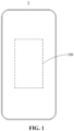
FIG. 1 is a schematic diagram of an electricity-consumption device according to embodiments of the disclosure. -
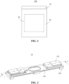
FIG. 2 is a schematic diagram of an energy storage apparatus according to embodiments of the disclosure. -
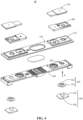
FIG. 3 is a schematic view of an end cover assembly according to embodiments of the disclosure. -
FIG. 4 is an exploded view of the end cover assembly inFIG. 3 . -
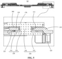
FIG. 5 is a cross-sectional view of the end cover assembly inFIG. 3 , taken along line i-i. -
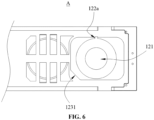
FIG. 6 is a partial schematic view of a top cover inFIG. 4 , viewed from direction A. -
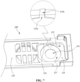
FIG. 7 is a schematic view of the top cover inFIG. 6 , viewed from in another direction. -
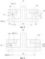
FIG. 8 is a schematic diagram illustrating that an end cover assembly is in a non-sealed state according to an embodiment of the disclosure. -
FIG. 9 is a schematic diagram illustrating that an end cover assembly is in a sealed state according to an embodiment of the disclosure. -
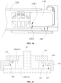
FIG. 10 is a schematic diagram illustrating assembly of a terminal post and a lower plastic member of the end cover assembly inFIG. 3 . -
FIG. 11 is a schematic diagram illustrating that an end cover assembly is in a non-sealed state according to another embodiment of the disclosure. -
FIG. 12 is a schematic diagram illustrating that an end cover assembly is in a sealed state according to another embodiment of the disclosure. - The technical solutions in the embodiments of the disclosure are clearly and completely described in the following with reference to the accompanying drawings in the embodiments of the disclosure. Apparently, the described embodiments are merely part of rather than all of the embodiments of the disclosure. All other embodiments obtained by those of ordinary skill in the art based on the embodiments of the disclosure without creative efforts are within the scope of the disclosure.
- Reference herein to terms "embodiment" or "example" means that specific features, structures, or characteristics described in combination with the embodiments or examples may be included in at least one embodiment or example of the disclosure. The above terms at various positions of the specification do not necessarily refer to the same embodiment or example, nor to separate or alternative embodiments mutually exclusive of other embodiments. It is apparent and implicitly understood by those of skill in the art that the embodiments described herein may be combined with other embodiments.
- As illustrated in
FIG. 1 , an electricity-consumption device 1 is provided in the disclosure. The electricity-consumption device 1 includes anenergy storage apparatus 100 described in the following embodiments. Theenergy storage apparatus 100 is configured to power the electricity-consumption device 1. The electricity-consumption device 1 may be, but is not limited to, a vehicle, an intelligent electronic device (such as a mobile phone or a computer), and the like. - As illustrated in
FIG. 2 , theenergy storage apparatus 100 is further provided in the disclosure. Theenergy storage apparatus 100 includes anelectrode assembly 20, ahousing 30, and anend cover assembly 10. Theelectrode assembly 20 is disposed in thehousing 30. Theend cover assembly 10 is electrically connected to theelectrode assembly 20. Theelectrode assembly 20 is configured to deliver electric energy outwards through theend cover assembly 10. Thehousing 30 is further provided with an electrolyte. Theelectrode assembly 20 is soaked in the electrolyte. Theenergy storage apparatus 100 may be a battery or a battery pack. The battery pack includes a box body and multiple batteries (greater than or equal to two batteries). The multiple batteries are received in the box body. The multiple batteries are electrically connected to one another. A shape of theenergy storage apparatus 100 may be, but is not limited to, a cylindrical shape, a cuboid shape, a cube shape, etc. Theenergy storage apparatus 100 may be applied in, but is not limited to, fields such as household energy storage, large-scale industry and commerce, 5Gbase stations, microgrids, integrated optical storage and charging, and virtual power plants. - As illustrated in
FIGs. 3 to 7 , theend cover assembly 10 is further provided in the disclosure. Theend cover assembly 10 includes atop cover 110, alower plastic member 120, a sealingmember 130, and aterminal post 140. The above components will be described in detail below with reference to the accompanying drawings. - The
top cover 110 may also be referred to as a smooth aluminum sheet, a top cover, a cover plate, and the like. Thetop cover 110 is generally made of a conductive material. In terms of structure, thetop cover 110 is insulated from theterminal post 140. - The
lower plastic member 120 is fixed to thetop cover 110. Thelower plastic member 120 is made of an insulating material. Thelower plastic member 120 may be made of a plastic material. In other embodiments, thelower plastic member 120 may also be made of a non-plastic material. Thelower plastic member 120 defines ahollow hole 121 and afirst flow passage 122a (as illustrated inFIG. 5 to FIG. 7 ). Thehollow hole 121 extends through thelower plastic member 120 in a direction from thelower plastic member 120 to thetop cover 110. That is, thehollow hole 121 is a through hole extending through thelower plastic member 120. Because thehollow hole 121 is a through hole, part of thetop cover 110 facing thehollow hole 121 is exposed. Thefirst flow passage 122a extends from thehollow hole 121 to an outside of thelower plastic member 120. That is, one end of thefirst flow passage 122a is in communication with a side wall of thehollow hole 121, and another end of thefirst flow passage 122a is in communication with an outside. A recess in communication with thehollow hole 121 is defined at an edge of thehollow hole 121 to form thefirst flow passage 122a. That is, the recess serves as thefirst flow passage 122a. - In the disclosure, the outside refers to a space outside the
end cover assembly 10. During assembly of theend cover assembly 10, air in a gap between thefirst sealing portion 131 and the side wall of thehollow hole 121 can be expelled to the space outside theend cover assembly 10 through thefirst flow passage 122a, thereby achieving an enhanced sealing effect of the sealingmember 130. - The sealing
member 130 includes a first sealing portion 131 (as illustrated inFIG. 5 ) disposed in thehollow hole 121. The sealingmember 130 may be made of an elastic and insulating material, such as rubber. - The
terminal post 140 includes a flange portion 141 (as illustrated inFIG. 5 ). Theflange portion 141 is disposed on one side of thefirst sealing portion 131 facing away from thetop cover 110 and covers thefirst sealing portion 131. Theflange portion 141 and thetop cover 110 cooperatively compress thefirst sealing portion 131. In other words, since thefirst sealing portion 131 is positioned in thehollow hole 121, thefirst sealing portion 131 is positioned between theflange portion 141 and thetop cover 110. Therefore, theflange portion 141 and thetop cover 110 cooperatively compress thefirst sealing portion 131, so that thefirst sealing portion 131 can seal a gap between theflange portion 141 and thetop cover 110. In addition, theflange portion 141 is insulated and separated from thetop cover 110 by thelower plastic member 120. That is, theflange portion 141 and thetop cover 110 are disposed on two opposite sides of thelower plastic member 120, respectively. Thelower plastic member 120 is configured to insulate and separate theflange portion 141 from thetop cover 110. It may be noted that, theterminal post 140 in the disclosure may be a positive terminal post or a negative terminal post of theenergy storage apparatus 100, which is not limited herein. - As illustrated in
FIG. 5 , theend cover assembly 10 further includes ametal block 170 and anupper plastic member 160. Themetal block 170 is disposed at one side of thetop cover 110 facing away from thelower plastic member 120. Theupper plastic member 160 is at least partially positioned between themetal block 170 and thetop cover 110. Theupper plastic member 160 is configured to insulate and separate themetal block 170 from thetop cover 110. Theupper plastic member 160 may be made of, but is not limited to, a plastic material. In some embodiments, when thelower plastic member 120 and theupper plastic member 160 are both made of plastic, thelower plastic member 120 may also be referred to as a lower plastic, and theupper plastic member 160 may also be referred to as an upper plastic. - As illustrated in
FIG. 5 , thetop cover 110 defines a throughhole 111, and the throughhole 111 faces thehollow hole 121. Theterminal post 140 further includes apost body 142 protruding from one side of theflange portion 141. One end of thepost body 142 facing away from theflange portion 141 extends through thehollow hole 121 and is electrically connected to themetal block 170. In theenergy storage apparatus 100, theelectrode assembly 20 is electrically connected to theflange portion 141 directly or indirectly. When theenergy storage apparatus 100 outputs electric energy to the outside, the electric energy is output through theflange portion 141, thepost body 142, and themetal block 170 in sequence. - Because the
top cover 110 defines the throughhole 111, it is required to prevent the electrolyte in theenergy storage apparatus 100 from leaking to the outside through the throughhole 111, or prevent external impurities from entering the interior of theenergy storage apparatus 100 through the throughhole 111 and contaminating the electrolyte. In the disclosure, thefirst sealing portion 131 of the sealingmember 130 is disposed between theflange portion 141 and thetop cover 110, so that a passage of theenergy storage apparatus 100 in the vicinity of the throughhole 111 can be blocked, thereby avoiding or weakening the described problem. - It may be noted that, during assembly of the
end cover assembly 10 provided in the disclosure, themetal block 170, thetop cover 110, and thelower plastic member 120 may be first stacked together, then theterminal post 140 is attached to thelower plastic member 120, and finally, one end of thepost body 142 of theterminal post 140 facing away from theflange portion 141 is connected to themetal block 170. During assembly, theterminal post 140 is moved in a direction from thelower plastic member 120 to thetop cover 110. - As illustrated in
FIG. 5 , a radial size of the throughhole 111 is less than a radial size of thehollow hole 121. Because the throughhole 111 faces thehollow hole 121, at least part of thetop cover 110 will be exposed to face thehollow hole 121, and thefirst sealing portion 131 disposed in thehollow hole 121 is in contact with part of thetop cover 110 that is exposed. That is, the radial size of the throughhole 111 is set to be less than the radial size of thehollow hole 121, thereby ensuring that thefirst sealing portion 131 can be positioned between thetop cover 110 and theflange portion 141. Therefore, thetop cover 110 and theflange portion 141 can cooperatively compress thefirst sealing portion 131, thereby ensuring that thefirst sealing portion 131 can achieve a sealing function. - As illustrated in
FIG. 5 , the sealingmember 130 further includes asecond sealing portion 132 protruding from one side of thefirst sealing portion 131. Thesecond sealing portion 132 has a hollow cylindrical shape. Thesecond sealing portion 132 extends through the throughhole 111 and is sleeved on an outer periphery of thepost body 142. That is, thesecond sealing portion 132 is positioned in the throughhole 111 and wraps around the outer periphery of thepost body 142. Thesecond sealing portion 132 may have at least two beneficial effects as follows. On the one hand, thesecond sealing portion 132 can seal the throughhole 111. On the other hand, thesecond sealing portion 132 can separate thepost body 142 from thetop cover 110. It may be understood that thesecond sealing portion 132 also facilitates mounting of the sealingmember 130. During assembly, thesecond sealing portion 132 can be positioned by the throughhole 111, and inserted into the throughhole 111, thereby mounting the sealingmember 130 while also ensuring that the sealingmember 130 is not easily displaced after mounting. - Further, the
end cover assembly 10 has a sealing state and a non-sealing state. The non-sealing state refers to a state of theend cover assembly 10 before a sealing assembly. The sealing state refers to a state of theend cover assembly 10 after the sealing assembly is completed. When theend cover assembly 10 is in the non-sealing state (as illustrated inFIG. 8 ), an outer diameter of thefirst sealing portion 131 is a first size R1, and the first size R1 is less than a diameter of thehollow hole 121. When theend cover assembly 10 is in the sealing state (as illustrated inFIG. 9 ), an outer diameter of thefirst sealing portion 131 is a second size R2, and the second size R2 is greater than the first size R1. During switch of theend cover assembly 10 from the non-sealed state to the sealed state, thefirst flow passage 122a is configured to expel air from thehollow hole 121. The non-sealing state may be understood as a state of theend cover assembly 10 in which thefirst sealing portion 131 is not compressed by theflange portion 141 and thetop cover 110. Accordingly, the sealed state may be understood as a state of theend cover assembly 10 in which thefirst sealing portion 131 is compressed by theflange portion 141 and thetop cover 110. - Specifically, when the
first sealing portion 131 is not compressed by theflange portion 141, the radial size of thefirst sealing portion 131 is less than the inner diameter of thehollow hole 121. In other words, a gap is defined between the outer periphery of thefirst sealing portion 131 and the side wall of thehollow hole 121. During movement of theflange portion 141 in the direction from thelower plastic member 120 to thetop cover 110, thefirst sealing portion 131 will expand in a radial direction of thefirst sealing portion 131 under cooperative compression of theflange portion 141 and thetop cover 110, thereby reducing the gap between thefirst sealing portion 131 and thehollow hole 121. It may be understood that, during reduction of the gap, air in the gap needs to be expelled for further compressing thefirst sealing portion 131. Otherwise, the air in the gap will hinder thefirst sealing portion 131 from expanding in the radial direction, resulting in poor sealing effect caused by an insufficient compression of thefirst sealing portion 131 by theflange portion 141. In the disclosure, thefirst flow passage 122a is defined on thelower plastic member 120, and thefirst flow passage 122a is in communication with thehollow hole 121 and extends to the outside of thelower plastic member 120. Therefore, during reduction of the gap between thefirst sealing portion 131 and thehollow hole 121, the air in the gap can be expelled from thefirst flow passage 122a to the outside of thelower plastic member 120. As a result, thefirst sealing portion 131 can be compressed continuously by theflange portion 141 to expand in the radial direction. Finally, thefirst sealing portion 131 can sufficiently seal the gap between theflange portion 141 and thetop cover 110. - The sealing
member 130 is generally an elastic member. The sealingmember 130 is deformed under compression, thereby tightly abutting against a contact surface to achieve a sealing effect. If air is not expelled from the contact surface, air bubbles can easily form during compression to affect mutual abutment between the sealingmember 130 and the contact surface, thereby reducing the sealing effect. In the disclosure, during assembly of theend cover assembly 10, an upper surface of theflange portion 141 of theterminal post 140 is moved to abut against thefirst sealing portion 131 of the sealingmember 130 and a lower surface of the lower plastic member 120 (i.e., a surface of thelower plastic member 120 facing towards the flange portion) 141. In this case, air between the lower surface of thelower plastic member 120, a lower surface of thefirst sealing portion 131, and the upper surface of theflange portion 141, as well as air between an outer peripheral wall of thefirst sealing portion 131 and an inner peripheral wall of thehollow hole 121, can be expelled through thefirst flow passage 122a, thereby avoiding formation of air bubbles and enhancing the sealing effect of the sealingmember 130. - In conclusion, in the
end cover assembly 10 provided in the disclosure, thefirst flow passage 122a is defined on thelower plastic member 120, and thefirst flow passage 122a is in communication with thehollow hole 121 and extends to the outside of thelower plastic member 120. During switch of theend cover assembly 10 from the non-sealing state to the sealing state (the radial size of thefirst sealing portion 131 is increased from the first size R1 to the second size R2), the air between the outer periphery of thefirst sealing portion 131 and the side wall of thehollow hole 121 can be expelled to the outside of thelower plastic member 120 through thefirst flow passage 122a. Therefore, during assembly, theflange portion 141 and thetop cover 110 may cooperate to smoothly compress thefirst sealing portion 131, so that thefirst sealing portion 131 can sufficiently seal the gap between theflange portion 141 and thetop cover 110. - As illustrated in
FIGs. 5 and7 , thelower plastic member 120 has anend surface 129. Theend surface 129 is a surface of thelower plastic member 120 facing away from thetop cover 110. Thelower plastic member 120 further defines anaccommodating recess 123. Theaccommodating recess 123 is recessed from theend surface 129. Theaccommodating recess 123 is in communication with thehollow hole 121. Theflange portion 141 is received in theaccommodating recess 123. It may be understood that, thelower plastic member 120 is mated with theflange portion 141 through theaccommodating recess 123, which facilitates stability of the connection between thelower plastic member 120 and theflange portion 141. Furthermore, theflange portion 141 is disposed in theaccommodating recess 123, so that thelower plastic member 120 is in interference fitting with theflange portion 141, thereby enhancing the sealing effect. In addition, because theaccommodating recess 123 is in communication with thehollow hole 121, during assembly of theflange portion 141 to theaccommodating recess 123, air in theaccommodating recess 123 may also be expelled through thefirst flow passage 122a. - As illustrated in
FIG. 7 , thelower plastic member 120 has afirst surface 124. Thefirst surface 124 serves as a side surface of theaccommodating recess 123. Asecond flow passage 122b is defined on thefirst surface 124. One end of thesecond flow passage 122b is in communication with thefirst flow passage 122a, and another end of thesecond flow passage 122b is in communication with the outside. That is, thesecond flow passage 122b is recessed from thefirst surface 124, and thesecond flow passage 122b extends through theend surface 129. Thesecond flow passage 122b extends through theend surface 129, so that thesecond flow passage 122b can be used to expel the air in thehollow hole 121 to the outside of thelower plastic member 120. In this embodiment, thesecond flow passage 122b may be a rectangular recess, an arc-shaped recess, or the like. The number of thesecond flow passages 122b may be one. Alternatively, the number of thesecond flow passages 122b may be more than one, for example, two, three, four, or the like. It may be understood that, the larger the number of thesecond flow passages 122b is, the faster the air is expelled, which facilitates quick assembly of theflange portion 141 and improves production efficiency. - Optionally, the
first flow passage 122a is curvedly connected to thesecond flow passage 122b. That is, a junction between thefirst flow passage 122a and thesecond flow passage 122b is curved. This arrangement can prevent an airflow, flowing from thefirst flow passage 122a to thesecond flow passage 122b, from hitting against the bottom of thesecond flow passage 122b to form a backflow when flowing through the junction between thefirst flow passage 122a and thesecond flow passage 122b. That is, the curved junction may play a role in guiding airflow, thereby improving capacity of air expelling. - Optionally, a width of the
first flow passage 122a (i.e., a width of a recess of thefirst flow passage 122a) ranges from 0.6 mm to 2.4 mm, and a width of thesecond flow passage 122b (i.e., a width of a recess of thesecond flow passage 122b) ranges from 0.6 mm to 2.4 mm. Specifically, the width of thefirst flow passage 122a may be 0.6 mm, 0.7 mm, 0.8 mm, 0.9 mm, 1.0 mm, 1.1 mm, 1.5 mm, 1.6 mm, 1.7 mm, 1.9 mm, 2.0 mm, 2.1 mm, 2.2 mm, 2.3 mm, 2.4 mm, and the like. The width of thesecond flow passage 122b may be 0.6 mm, 0.7 mm, 0.8 mm, 0.9 mm, 1.0 mm, 1.1 mm, 1.5 mm, 1.6 mm, 1.7 mm, 1.9 mm, 2.0 mm, 2.1 mm, 2.2 mm, 2.3 mm, 2.4 mm, and the like. - Optionally, a depth of the
first flow passage 122a (i.e., a depth of the recess of thefirst flow passage 122a) ranges from 0.2 mm to 2.8 mm, and a depth of thesecond flow passage 122b (i.e., a depth of the recess of thesecond flow passage 122b) ranges from 0.2 mm to 2.8 mm. Specifically, the depth of thefirst flow passage 122a may be 0.2 mm, 0.5 mm, 0.6 mm, 0.8 mm, 0.9 mm, 1.0 mm, 1.1 mm, 1.2 mm, 1.6 mm, 1.9 mm, 2.1 mm, 2.2 mm, 2.5 mm, 2.6 mm, 2.8 mm, and the like. The depth of thesecond flow passage 122b may be 0.2 mm, 0.5 mm, 0.6 mm, 0.8 mm, 0.9 mm, 1.0 mm, 1.1 mm, 1.2 mm, 1.6 mm, 1.9 mm, 2.1 mm, 2.2 mm, 2.5 mm, 2.6 mm, 2.8 mm, and the like. - As illustrated in
FIG. 10 , theflange portion 141 is provided with a fool-proof portion 1411, and theaccommodating recess 123 is provided with afitting portion 1231 matching the fool-proof portion 1411. In this embodiment, to ensure quick and correct mounting of theterminal post 140, theflange portion 141 is provided with the fool-proof portion 1411, theaccommodating recess 123 is correspondingly provided with thefitting portion 1231, and the fool-proof portion 1411 matches thefitting portion 1231. During assembly, an operator only need to align and assemble the fool-proof portion 1411 and thefitting portion 1231, thereby achieving a convenient and quick assembly, and ensuring that theterminal post 140 is not misaligned with thelower plastic member 120 after assembly. The fool-proof portion 1411 may be disposed at any position of a peripheral edge of theflange portion 141, for example, a side edge or a corner of theflange portion 141. The fool-proof portion 1411 may be a protrusion or a notch on theflange portion 141. Regardless of the form of the fool-proof portion 1411, thefitting portion 1231 is set to be in a shape that can mate with the fool-proof portion 1411. In this embodiment, with the aid of the fool-proof portion 1411 and thefitting portion 1231, at least the following two beneficial effects may be brought about. On the one hand, theterminal post 140 is precisely limited. On the other hand, the sealing performance of mating between theterminal post 140 and thelower plastic member 120 is further enhanced. - Further, the
lower plastic member 120 has afirst surface 124 serving as a side surface of theaccommodating recess 123 and abutting against theflange portion 141 of theterminal post 140. This arrangement can further enhance the sealing performance of mating between theterminal post 140 and thelower plastic member 120. - As illustrated in
FIGs. 11 and12 , thelower plastic member 120 has asecond surface 125 facing away from thetop cover 110. Apart of thesecond surface 125 is defined as a bottom surface of theaccommodating recess 123. That is, a part of thesecond surface 125 serves as the bottom surface of theaccommodating recess 123. Thelower plastic member 120 further defines arecess 127 recessed from thesecond surface 125. Therecess 127 surrounds thehollow hole 121 and is in communication with thehollow hole 121. That is, therecess 127 is annular. When theend cover assembly 10 is in the non-sealing state, thefirst sealing portion 131 is positioned outside therecess 127. When theend cover assembly 10 is in the sealing state, at least part of thefirst sealing portion 131 is positioned in therecess 127. - Specifically, because the
lower plastic member 120 defines therecess 127, a step structure (defined as afirst step structure 128 herein) is formed at a position where therecess 127 is positioned. During expansion of thefirst sealing portion 131 in the radial direction of the first sealing portion 131 (namely, during switch of theend cover assembly 10 from the non-sealing state to the sealing state), the outer periphery of thefirst sealing portion 131 gradually enters therecess 127 from thehollow hole 121, and gradually compresses thefirst step structure 128 on thelower plastic member 120. The outer periphery of thefirst sealing portion 131 will also form a step structure (defined as asecond step structure 1311 herein) under continuous compression. Thesecond step structure 1311 and thefirst step structure 128 have the same shape and are stacked to form a fitting state, as illustrated inFIG. 12 . It may be understood that, the tight fitting state of thefirst step structure 128 and thesecond step structure 1311 can further enhance the sealing performance. In addition, the step structure can also increase a creep age distance, thereby improving the safety performance of theenergy storage apparatus 100. - In summary, with the aid of the
recess 127, at least the following two beneficial effects can be brought about. On the one hand, therecess 127 enables an abutting surface between the outer peripheral wall of thefirst sealing portion 131 and the inner peripheral wall of thehollow hole 121 of the sealingmember 130 to be extended into a Z-shape, increasing a contact area between the outer peripheral wall of thefirst sealing portion 131 and the inner peripheral wall of thehollow hole 121 of thelower plastic member 120, and further enhancing the sealing effect. On the other hand, the creep age distance between theflange portion 141 of the terminal post and thetop cover 110 is increased, thereby improving the electrical safety performance. - As illustrated in
FIG. 7 , thefirst flow passage 122a is recessed from thesecond surface 125. One end of thefirst flow passage 122a is in communication with therecess 127, and another end of thefirst flow passage 122a is in communication with thesecond flow passage 122b. - As illustrated in
FIGs. 8 and 9 , when the sealingmember 130 is assembled in thehollow hole 121 of thelower plastic member 120 and is not compressed (as illustrated inFIG. 8 ), a gap is defined between an outer peripheral surface of thefirst sealing portion 131 and a side surface of thehollow hole 121. Thelower plastic member 120 has asecond surface 125 and athird surface 126 that abuts against a surface of thetop cover 110. A part of thesecond surface 125 serves as a bottom surface of theaccommodating recess 123. A distance between thesecond surface 125 and thethird surface 126 is H2, and a thickness of thefirst sealing portion 131 is H1, and H1 is greater than H2. That is, thefirst sealing portion 131 protrudes from thesecond surface 125 in a direction from thethird surface 126 to thesecond surface 125. Here, the thickness of thefirst sealing portion 131 refers to a size of thefirst sealing portion 131 in the opposite direction of thesecond surface 125 and thethird surface 126. - During mating of the sealing
member 130 with thehollow hole 121 of thelower plastic member 120 and compression of thefirst sealing portion 131 by theflange portion 141 of theterminal post 140, the thickness H1 of thefirst sealing portion 131 decreases, and thefirst sealing portion 131 expands in the radial direction of thefirst sealing portion 131. The gap between the outer periphery of thefirst sealing portion 131 and the side wall of thehollow hole 121 is gradually filled by thefirst sealing portion 131, until the seal assembly as illustrated inFIG. 9 is achieved. - In this embodiment, since H1 is greater than H2, it can be ensured that the
terminal post 140 can compress thefirst sealing portion 131 in the thickness direction of thefirst sealing portion 131 during assembly, so that adjacent components are in close contact with each other, thereby improving sealing performance. - During assembly of the
end cover assembly 10, when theflange portion 141 of theterminal post 140 is just inserted into theaccommodating recess 123, a space defined by theflange portion 141 of theterminal post 140, thefirst sealing portion 131 of the sealingmember 130, thelower plastic member 120, and thetop cover 110 is relatively closed, and the space is simply referred to as a closed space (seeFIG. 11 ). Theflange portion 141 is continue moved upward to compress thefirst sealing portion 131, and thefirst sealing portion 131 is compressed to be thinner and expand outwards, the gap between the outer peripheral wall of thefirst sealing portion 131 and the inner peripheral wall of thehollow hole 121 is closed (seeFIG. 12 ), and air in the gap and air in the closed space can be smoothly expelled through thefirst flow passage 122a and thesecond flow passage 122b. In this way, no air bubble will form in the closed space, thereby enhancing the sealing performance between theterminal post 140 and thetop cover 110, and further improving the durability of theenergy storage apparatus 100. - Alternatively, a reduction in the thickness of the
first sealing portion 131 subject to compression is (H1-H2), and a size of the gap between the outer peripheral surface of thefirst sealing portion 131 and the side surface of thehollow hole 121 is H3, where 0.9 ≤ (H1-H2)/H3 ≤ 1.6. That is, a ratio of (H1-H2) to H3 ranges from 0.9 to 1.6. With this arrangement, it can be ensured that thefirst sealing portion 131 can expand outwards under compression to fill the gap and abut against the side surface of thehollow hole 121, thereby further enhancing the sealing performance. The ratio of (H1-H2) to H3 can be, but is not limited to, 0.9, 1.0, 1.1, 1.2, 1.25, 1.3, 1.4, 1.5, 1.6, etc. - Optionally, the thickness H1 of the
first sealing portion 131, when not compressed, ranges from 0.8mm to 3mm. Specifically, the thickness H1 of thefirst sealing portion 131, when not compressed, may be 0.8mm, 0.9mm, 1.0mm, 1.1mm, 1.15mm, 1.2mm, 1.5mm, 1.8mm, 2.0mm, 2.3mm, 2.5mm, 2.6mm, 2.9mm, 3.0mm, and the like. - Alternatively, the size of the gap H3 between the outer peripheral surface of the
first sealing portion 131 and the side surface of thehollow hole 121 ranges from 0.05 mm to 1.85 mm. Specifically, the size of the gap H3 may be 0.05 mm, 0.06 mm, 0.10 mm, 0.15 mm, 0.20 mm, 0.26 mm, 0.3 mm, 0.41 mm, 0.5 mm, 0.55 mm, 0.6 mm, 0.9 mm, 1.5 mm, 1.85 mm, and the like. If H3 < 0.05 mm, thefirst sealing portion 131 may not sufficiently expand in the radial direction, so that thefirst sealing portion 131 cannot be further compressed by theflange portion 141, finally resulting in a poor sealing effect. If H3 > 1.85, H3 may be still greater than zero when theend cover assembly 10 is in the sealed state, that is, the side wall of thehollow hole 121 and an edge of thefirst sealing portion 131 will not abut against each other, resulting in a poor sealing effect. - Although the embodiments of the disclosure have been illustrated and described, it may be understood that the above embodiments are illustrative and cannot be construed as limitations to the disclosure. Those skilled in the art can make changes, modifications, replacements, and variations to the above embodiments within the scope of the disclosure, and these changes and modifications shall also belong to the scope of protection of the disclosure.
Claims (15)
- An end cover assembly (10), comprising:a top cover (110);a lower plastic member (120), wherein the lower plastic member (120) is fixed to the top cover (110) and defines a hollow hole (121) and a first flow passage (122a), the hollow hole (121) extends through the lower plastic member (120) in a direction from the lower plastic member (120) to the top cover (110), one end of the first flow passage (122a) is in communication with a side wall of the hollow hole (121), and another end of the first flow passage (122a) is in communication with an outside;a sealing member (130) comprising a first sealing portion (131) disposed in the hollow hole (121); anda terminal post (140) comprising a flange portion (141), wherein the flange portion (141) is disposed on one side of the first sealing portion (131) facing away from the top cover (110) and covers the first sealing portion (131), the flange portion (141) and the top cover (110) cooperatively compress the first sealing portion (131), and the flange portion (141) is insulated and separated from the top cover (110) by the lower plastic member (120);wherein the lower plastic member (120) further defines a second flow passage (122b), one end of the second flow passage (122b) is in communication with the first flow passage (122a), and another end of the second flow passage (122b) is in communication with the outside, the second flow passage (122b) is connected to the first flow passage (122a) in a bent manner, and the first flow passage (122a) is curvedly connected to the second flow passage (122b).
- The end cover assembly (10) of claim 1, wherein a recess in communication with the hollow hole (121) is defined at an edge of the hollow hole (121) to serve as the first flow passage (122a).
- The end cover assembly (10) of claim 1 or 2, wherein the lower plastic member (120) has an end surface (129) facing away from the top cover (110) and further defines an accommodating recess (123), the accommodating recess (123) is recessed from the end surface (129) and in communication with the hollow hole (121), and the flange portion (141) is received in the accommodating recess (123).
- The end cover assembly (10) of claim 3, wherein the lower plastic member (120) has a first surface (124), the first surface (124) serves as a side surface of the accommodating recess (123), the second flow passage (122b) is defined on the first surface (124).
- The end cover assembly (10) of claim 3, wherein the flange portion (141) is provided with a fool-proof portion (1411), and the accommodating recess (123) is provided with a fitting portion (1231) matching the fool-proof portion (1411);
the lower plastic member (120) has a first surface (124) serving as a side surface of the accommodating recess (123) and abutting against the flange portion (141) of the terminal post (140). - The end cover assembly (10) of any one of claims 3 to 5, wherein the lower plastic member (120) has a second surface (125), a part of the second surface (125) serves as a bottom surface of the accommodating recess (123), the lower plastic member (120) further defines a recess (127) recessed from the second surface (125), the recess (127) is annular and is in communication with the hollow hole (121) to form a step structure.
- The end cover assembly (10) of claim 6, wherein the first flow passage (122a) is recessed from the second surface (125) and is in communication with the recess (127).
- The end cover assembly (10) of claim 3, wherein when the sealing member (130) is assembled in the hollow hole (121) of the lower plastic member (120) and is not compressed, a gap is defined between an outer peripheral surface of the first sealing portion (131) and a side surface of the hollow hole (121), a thickness of the first sealing portion (131) is H1, the lower plastic member (120) has a second surface (125) and a third surface (126) that abuts against a surface of the top cover (110), a part of the second surface (125) serves as a bottom surface of the accommodating recess (123), and a distance between the second surface (125) and the third surface (126) is H2, wherein H1 is greater than H2.
- The end cover assembly (10) of claim 8, wherein a reduction in a thickness of the first sealing portion (131) subject to compression deformation is H1-H2, and a size of the gap between the outer peripheral surface of the first sealing portion (131) and the side surface of the hollow hole (121) is H3, wherein 0.9 ≤ (H1-H2)/H3 ≤ 1.6.
- The end cover assembly (10) of claim 8 or 9, wherein the thickness H1 of the first sealing portion (131) ranges from 0.8 mm to 3 mm.
- The end cover assembly (10) of any one of claims 8 to 10, wherein the size of the gap between the outer peripheral surface of the first sealing portion (131) and the side surface of the hollow hole (121) ranges from 0.05 mm to 1.85 mm.
- The end cover assembly (10) of any one of claims 1 to 11, further comprising a metal block (170), wherein the metal block (170) is disposed on one side of the top cover (110) facing away from the lower plastic member (120), the top cover (110) defines a through hole (111) facing towards the hollow hole (121), the terminal post (140) further comprises a post body (142) protruding from one side of the flange portion (141), and one end of the post body (142) facing away from the flange portion (141) extends through the through hole (111) to connect to the metal block (170).
- The end cover assembly (10) of claim 12, wherein the sealing member (130) further comprises a second sealing portion (132) protruding from one side of the first sealing portion (131), and the second sealing portion (132) extends through the through hole (111) and is sleeved on an outer periphery of the post body (142).
- An energy storage apparatus (100) comprising an electrode assembly (20), a housing (30), and the end cover assembly (10) of any one of claims 1-13, wherein the electrode assembly (20) is received in the housing (30), and the end cover assembly (10) is electrically connected to the electrode assembly (20).
- An electricity-consumption device (1) comprising the energy storage apparatus (100) of claim 14, wherein the energy storage apparatus (100) is configured to power the electricity-consumption device (1).
Applications Claiming Priority (1)
| Application Number | Priority Date | Filing Date | Title |
|---|---|---|---|
| CN202310091084.3A CN115810841B (en) | 2023-02-09 | 2023-02-09 | End cover assembly, energy storage device and electric equipment |
Publications (2)
| Publication Number | Publication Date |
|---|---|
| EP4415134A1 true EP4415134A1 (en) | 2024-08-14 |
| EP4415134B1 EP4415134B1 (en) | 2025-09-24 |
Family
ID=85487821
Family Applications (1)
| Application Number | Title | Priority Date | Filing Date |
|---|---|---|---|
| EP23218192.5A Active EP4415134B1 (en) | 2023-02-09 | 2023-12-19 | End cover assembly, energy storage apparatus, and electricity-consumption device |
Country Status (4)
| Country | Link |
|---|---|
| US (1) | US12057590B1 (en) |
| EP (1) | EP4415134B1 (en) |
| CN (1) | CN115810841B (en) |
| ES (1) | ES3054400T3 (en) |
Families Citing this family (2)
| Publication number | Priority date | Publication date | Assignee | Title |
|---|---|---|---|---|
| CN116207462B (en) * | 2023-03-30 | 2024-05-31 | 厦门海辰储能科技股份有限公司 | End cover assembly, energy storage device and electrical equipment |
| CN116864881B (en) * | 2023-09-05 | 2023-12-29 | 中宏科创新能源科技(浙江)有限公司 | Top cap subassembly, battery and electronic equipment |
Citations (2)
| Publication number | Priority date | Publication date | Assignee | Title |
|---|---|---|---|---|
| CN113270667A (en) * | 2020-11-11 | 2021-08-17 | 厦门海辰新能源科技有限公司 | Top cap subassembly and have its lithium cell |
| CN217848117U (en) * | 2022-07-14 | 2022-11-18 | 蜂巢能源科技股份有限公司 | Battery cover plate, battery with same and power device |
Family Cites Families (17)
| Publication number | Priority date | Publication date | Assignee | Title |
|---|---|---|---|---|
| CN101587965B (en) * | 2009-04-24 | 2010-12-08 | 湖南神舟科技股份有限公司 | Internally-connected square plastic accumulator |
| DE102017216874A1 (en) | 2017-09-25 | 2019-03-28 | Robert Bosch Gmbh | Cover plate for a battery cell and method for producing a cover plate |
| CN110021728B (en) * | 2018-01-10 | 2021-11-09 | 宁德时代新能源科技股份有限公司 | One-way vent valve, secondary battery's top cap subassembly and secondary battery |
| CN208986033U (en) | 2018-08-08 | 2019-06-14 | 深圳市瑞德丰精密制造有限公司 | Ring structure, battery terminal post structure and battery cover board for battery electrode column |
| CN209747563U (en) | 2019-05-27 | 2019-12-06 | 宁德时代新能源科技股份有限公司 | Top cover assembly and secondary battery |
| CN110379953A (en) * | 2019-07-31 | 2019-10-25 | 江苏塔菲尔新能源科技股份有限公司 | A kind of assembling structure and its assembly method of battery cap |
| CN210272526U (en) | 2019-09-18 | 2020-04-07 | 东莞百思利新能源科技有限公司 | Secondary battery pole assembly and secondary battery top cover thereof |
| CN213401337U (en) * | 2020-10-16 | 2021-06-08 | 东莞塔菲尔新能源科技有限公司 | Assembly structure of power battery top cover and power battery |
| CN215451569U (en) | 2021-04-13 | 2022-01-07 | 欣旺达电动汽车电池有限公司 | Battery top cap and electric core |
| CN215266471U (en) | 2021-06-04 | 2021-12-21 | 欣旺达电动汽车电池有限公司 | Power battery top cap and power battery |
| CN113178651B (en) * | 2021-06-07 | 2021-08-24 | 蜂巢能源科技有限公司 | Battery pole sealing installation structure and installation method thereof |
| CN215896540U (en) | 2021-08-12 | 2022-02-22 | 湖北亿纬动力有限公司 | Top cover structure and battery |
| CN215869708U (en) | 2021-08-20 | 2022-02-18 | 苏州炬鸿通讯电脑科技有限公司 | High-capacity and high-performance lithium battery cover plate structure |
| CN217361751U (en) | 2022-01-28 | 2022-09-02 | 上海兰钧新能源科技有限公司 | Plastic structure under secondary battery |
| CN217507473U (en) * | 2022-06-10 | 2022-09-27 | 中创新航科技股份有限公司 | Battery pack |
| CN218039495U (en) * | 2022-07-28 | 2022-12-13 | 湖北亿纬动力有限公司 | Top cover assembly and power battery |
| CN218039478U (en) * | 2022-07-28 | 2022-12-13 | 湖北亿纬动力有限公司 | Plastic part, top cap subassembly and battery |
-
2023
- 2023-02-09 CN CN202310091084.3A patent/CN115810841B/en active Active
- 2023-11-30 US US18/525,461 patent/US12057590B1/en active Active
- 2023-12-19 ES ES23218192T patent/ES3054400T3/en active Active
- 2023-12-19 EP EP23218192.5A patent/EP4415134B1/en active Active
Patent Citations (2)
| Publication number | Priority date | Publication date | Assignee | Title |
|---|---|---|---|---|
| CN113270667A (en) * | 2020-11-11 | 2021-08-17 | 厦门海辰新能源科技有限公司 | Top cap subassembly and have its lithium cell |
| CN217848117U (en) * | 2022-07-14 | 2022-11-18 | 蜂巢能源科技股份有限公司 | Battery cover plate, battery with same and power device |
Also Published As
| Publication number | Publication date |
|---|---|
| EP4415134B1 (en) | 2025-09-24 |
| US12057590B1 (en) | 2024-08-06 |
| US20240274940A1 (en) | 2024-08-15 |
| CN115810841A (en) | 2023-03-17 |
| CN115810841B (en) | 2023-05-09 |
| ES3054400T3 (en) | 2026-02-03 |
Similar Documents
| Publication | Publication Date | Title |
|---|---|---|
| KR100467703B1 (en) | Cap assembly and secondary battery applying the same | |
| EP4415134A1 (en) | End cover assembly, energy storage apparatus, and electricity-consumption device | |
| CN100495800C (en) | Secondary battery | |
| CN106058134B (en) | rechargeable battery | |
| US11721861B2 (en) | Top cover assembly for battery, battery, and energy storage device | |
| KR20090081197A (en) | Rechargeable battery | |
| CN115882176A (en) | Insulation components, end cover components, energy storage devices and electrical equipment | |
| WO2023036291A1 (en) | Composite pole, top cover, and battery | |
| US20250158178A1 (en) | Battery, battery module, and electric device | |
| CN116231179A (en) | End cap assembly, battery and energy storage device | |
| US20240266642A1 (en) | Battery housing, lithium battery and electronic product thereof | |
| US8771865B2 (en) | Secondary battery | |
| CN216850095U (en) | Battery pack with compact structure | |
| CN207690845U (en) | Secondary cell cap assembly, secondary cell and automobile | |
| CN221328040U (en) | Secondary batteries and battery packs | |
| KR20040022715A (en) | Lithium secondary battery | |
| WO2024094179A1 (en) | End cover assembly of battery, battery cell, energy storage device, and electrical apparatus | |
| CN214226975U (en) | Button battery packaging structure and button battery | |
| KR102940749B1 (en) | Secondary Battery and Manufacturing Method of Secondary Battery | |
| US20250364651A1 (en) | Insulation assembly, end cover assembly, energy storage device, and electric device | |
| CN223109038U (en) | Battery | |
| CN222483513U (en) | Battery case and battery | |
| CN219419255U (en) | Battery cell | |
| KR20030053601A (en) | Secondary battery | |
| CN116864881B (en) | Top cap subassembly, battery and electronic equipment |
Legal Events
| Date | Code | Title | Description |
|---|---|---|---|
| PUAI | Public reference made under article 153(3) epc to a published international application that has entered the european phase |
Free format text: ORIGINAL CODE: 0009012 |
|
| STAA | Information on the status of an ep patent application or granted ep patent |
Free format text: STATUS: THE APPLICATION HAS BEEN PUBLISHED |
|
| AK | Designated contracting states |
Kind code of ref document: A1 Designated state(s): AL AT BE BG CH CY CZ DE DK EE ES FI FR GB GR HR HU IE IS IT LI LT LU LV MC ME MK MT NL NO PL PT RO RS SE SI SK SM TR |
|
| STAA | Information on the status of an ep patent application or granted ep patent |
Free format text: STATUS: REQUEST FOR EXAMINATION WAS MADE |
|
| 17P | Request for examination filed |
Effective date: 20240917 |
|
| RBV | Designated contracting states (corrected) |
Designated state(s): AL AT BE BG CH CY CZ DE DK EE ES FI FR GB GR HR HU IE IS IT LI LT LU LV MC ME MK MT NL NO PL PT RO RS SE SI SK SM TR |
|
| STAA | Information on the status of an ep patent application or granted ep patent |
Free format text: STATUS: EXAMINATION IS IN PROGRESS |
|
| 17Q | First examination report despatched |
Effective date: 20241211 |
|
| RAP1 | Party data changed (applicant data changed or rights of an application transferred) |
Owner name: HITHIUM TECH HK LIMITED |
|
| GRAP | Despatch of communication of intention to grant a patent |
Free format text: ORIGINAL CODE: EPIDOSNIGR1 |
|
| STAA | Information on the status of an ep patent application or granted ep patent |
Free format text: STATUS: GRANT OF PATENT IS INTENDED |
|
| INTG | Intention to grant announced |
Effective date: 20250424 |
|
| GRAS | Grant fee paid |
Free format text: ORIGINAL CODE: EPIDOSNIGR3 |
|
| GRAA | (expected) grant |
Free format text: ORIGINAL CODE: 0009210 |
|
| STAA | Information on the status of an ep patent application or granted ep patent |
Free format text: STATUS: THE PATENT HAS BEEN GRANTED |
|
| AK | Designated contracting states |
Kind code of ref document: B1 Designated state(s): AL AT BE BG CH CY CZ DE DK EE ES FI FR GB GR HR HU IE IS IT LI LT LU LV MC ME MK MT NL NO PL PT RO RS SE SI SK SM TR |
|
| REG | Reference to a national code |
Ref country code: GB Ref legal event code: FG4D |
|
| REG | Reference to a national code |
Ref country code: CH Ref legal event code: EP |
|
| REG | Reference to a national code |
Ref country code: DE Ref legal event code: R096 Ref document number: 602023006944 Country of ref document: DE |
|
| REG | Reference to a national code |
Ref country code: IE Ref legal event code: FG4D |
|
| PGFP | Annual fee paid to national office [announced via postgrant information from national office to epo] |
Ref country code: DE Payment date: 20251212 Year of fee payment: 3 |
|
| PG25 | Lapsed in a contracting state [announced via postgrant information from national office to epo] |
Ref country code: NO Free format text: LAPSE BECAUSE OF FAILURE TO SUBMIT A TRANSLATION OF THE DESCRIPTION OR TO PAY THE FEE WITHIN THE PRESCRIBED TIME-LIMIT Effective date: 20251224 |
|
| REG | Reference to a national code |
Ref country code: LT Ref legal event code: MG9D |
|
| PGFP | Annual fee paid to national office [announced via postgrant information from national office to epo] |
Ref country code: AT Payment date: 20260113 Year of fee payment: 3 |
|
| PG25 | Lapsed in a contracting state [announced via postgrant information from national office to epo] |
Ref country code: FI Free format text: LAPSE BECAUSE OF FAILURE TO SUBMIT A TRANSLATION OF THE DESCRIPTION OR TO PAY THE FEE WITHIN THE PRESCRIBED TIME-LIMIT Effective date: 20250924 |
|
| PG25 | Lapsed in a contracting state [announced via postgrant information from national office to epo] |
Ref country code: HR Free format text: LAPSE BECAUSE OF FAILURE TO SUBMIT A TRANSLATION OF THE DESCRIPTION OR TO PAY THE FEE WITHIN THE PRESCRIBED TIME-LIMIT Effective date: 20250924 |
|
| PGFP | Annual fee paid to national office [announced via postgrant information from national office to epo] |
Ref country code: HU Payment date: 20251209 Year of fee payment: 3 |
|
| PG25 | Lapsed in a contracting state [announced via postgrant information from national office to epo] |
Ref country code: GR Free format text: LAPSE BECAUSE OF FAILURE TO SUBMIT A TRANSLATION OF THE DESCRIPTION OR TO PAY THE FEE WITHIN THE PRESCRIBED TIME-LIMIT Effective date: 20251225 |
|
| PG25 | Lapsed in a contracting state [announced via postgrant information from national office to epo] |
Ref country code: SE Free format text: LAPSE BECAUSE OF FAILURE TO SUBMIT A TRANSLATION OF THE DESCRIPTION OR TO PAY THE FEE WITHIN THE PRESCRIBED TIME-LIMIT Effective date: 20250924 |
|
| PG25 | Lapsed in a contracting state [announced via postgrant information from national office to epo] |
Ref country code: LV Free format text: LAPSE BECAUSE OF FAILURE TO SUBMIT A TRANSLATION OF THE DESCRIPTION OR TO PAY THE FEE WITHIN THE PRESCRIBED TIME-LIMIT Effective date: 20250924 |
|
| PG25 | Lapsed in a contracting state [announced via postgrant information from national office to epo] |
Ref country code: BG Free format text: LAPSE BECAUSE OF FAILURE TO SUBMIT A TRANSLATION OF THE DESCRIPTION OR TO PAY THE FEE WITHIN THE PRESCRIBED TIME-LIMIT Effective date: 20250924 |
|
| PG25 | Lapsed in a contracting state [announced via postgrant information from national office to epo] |
Ref country code: RS Free format text: LAPSE BECAUSE OF FAILURE TO SUBMIT A TRANSLATION OF THE DESCRIPTION OR TO PAY THE FEE WITHIN THE PRESCRIBED TIME-LIMIT Effective date: 20251224 |
|
| REG | Reference to a national code |
Ref country code: NL Ref legal event code: MP Effective date: 20250924 |
|
| REG | Reference to a national code |
Ref country code: ES Ref legal event code: FG2A Ref document number: 3054400 Country of ref document: ES Kind code of ref document: T3 Effective date: 20260203 |
|
| PG25 | Lapsed in a contracting state [announced via postgrant information from national office to epo] |
Ref country code: NL Free format text: LAPSE BECAUSE OF FAILURE TO SUBMIT A TRANSLATION OF THE DESCRIPTION OR TO PAY THE FEE WITHIN THE PRESCRIBED TIME-LIMIT Effective date: 20250924 |
|
| PG25 | Lapsed in a contracting state [announced via postgrant information from national office to epo] |
Ref country code: SM Free format text: LAPSE BECAUSE OF FAILURE TO SUBMIT A TRANSLATION OF THE DESCRIPTION OR TO PAY THE FEE WITHIN THE PRESCRIBED TIME-LIMIT Effective date: 20250924 |
|
| PGFP | Annual fee paid to national office [announced via postgrant information from national office to epo] |
Ref country code: ES Payment date: 20260105 Year of fee payment: 3 |
|
| PG25 | Lapsed in a contracting state [announced via postgrant information from national office to epo] |
Ref country code: RO Free format text: LAPSE BECAUSE OF FAILURE TO SUBMIT A TRANSLATION OF THE DESCRIPTION OR TO PAY THE FEE WITHIN THE PRESCRIBED TIME-LIMIT Effective date: 20250924 Ref country code: IT Free format text: LAPSE BECAUSE OF FAILURE TO SUBMIT A TRANSLATION OF THE DESCRIPTION OR TO PAY THE FEE WITHIN THE PRESCRIBED TIME-LIMIT Effective date: 20250924 |
|
| PG25 | Lapsed in a contracting state [announced via postgrant information from national office to epo] |
Ref country code: IS Free format text: LAPSE BECAUSE OF FAILURE TO SUBMIT A TRANSLATION OF THE DESCRIPTION OR TO PAY THE FEE WITHIN THE PRESCRIBED TIME-LIMIT Effective date: 20260124 |
|
| PG25 | Lapsed in a contracting state [announced via postgrant information from national office to epo] |
Ref country code: CZ Free format text: LAPSE BECAUSE OF FAILURE TO SUBMIT A TRANSLATION OF THE DESCRIPTION OR TO PAY THE FEE WITHIN THE PRESCRIBED TIME-LIMIT Effective date: 20250924 Ref country code: PT Free format text: LAPSE BECAUSE OF FAILURE TO SUBMIT A TRANSLATION OF THE DESCRIPTION OR TO PAY THE FEE WITHIN THE PRESCRIBED TIME-LIMIT Effective date: 20260126 |
|
| PG25 | Lapsed in a contracting state [announced via postgrant information from national office to epo] |
Ref country code: PL Free format text: LAPSE BECAUSE OF FAILURE TO SUBMIT A TRANSLATION OF THE DESCRIPTION OR TO PAY THE FEE WITHIN THE PRESCRIBED TIME-LIMIT Effective date: 20250924 |
|
| PG25 | Lapsed in a contracting state [announced via postgrant information from national office to epo] |
Ref country code: EE Free format text: LAPSE BECAUSE OF FAILURE TO SUBMIT A TRANSLATION OF THE DESCRIPTION OR TO PAY THE FEE WITHIN THE PRESCRIBED TIME-LIMIT Effective date: 20250924 Ref country code: SK Free format text: LAPSE BECAUSE OF FAILURE TO SUBMIT A TRANSLATION OF THE DESCRIPTION OR TO PAY THE FEE WITHIN THE PRESCRIBED TIME-LIMIT Effective date: 20250924 |