EP4415132A1 - End cover assembly, energy storage apparatus, and electricity-consumption device - Google Patents
End cover assembly, energy storage apparatus, and electricity-consumption device Download PDFInfo
- Publication number
- EP4415132A1 EP4415132A1 EP23218224.6A EP23218224A EP4415132A1 EP 4415132 A1 EP4415132 A1 EP 4415132A1 EP 23218224 A EP23218224 A EP 23218224A EP 4415132 A1 EP4415132 A1 EP 4415132A1
- Authority
- EP
- European Patent Office
- Prior art keywords
- hole
- fitting
- plastic member
- mounting
- groove
- Prior art date
- Legal status (The legal status is an assumption and is not a legal conclusion. Google has not performed a legal analysis and makes no representation as to the accuracy of the status listed.)
- Granted
Links
Images



Classifications
-
- H—ELECTRICITY
- H01—ELECTRIC ELEMENTS
- H01M—PROCESSES OR MEANS, e.g. BATTERIES, FOR THE DIRECT CONVERSION OF CHEMICAL ENERGY INTO ELECTRICAL ENERGY
- H01M50/00—Constructional details or processes of manufacture of the non-active parts of electrochemical cells other than fuel cells, e.g. hybrid cells
- H01M50/10—Primary casings; Jackets or wrappings
- H01M50/147—Lids or covers
- H01M50/148—Lids or covers characterised by their shape
- H01M50/15—Lids or covers characterised by their shape for prismatic or rectangular cells
-
- H—ELECTRICITY
- H01—ELECTRIC ELEMENTS
- H01M—PROCESSES OR MEANS, e.g. BATTERIES, FOR THE DIRECT CONVERSION OF CHEMICAL ENERGY INTO ELECTRICAL ENERGY
- H01M50/00—Constructional details or processes of manufacture of the non-active parts of electrochemical cells other than fuel cells, e.g. hybrid cells
- H01M50/10—Primary casings; Jackets or wrappings
- H01M50/102—Primary casings; Jackets or wrappings characterised by their shape or physical structure
- H01M50/103—Primary casings; Jackets or wrappings characterised by their shape or physical structure prismatic or rectangular
-
- H—ELECTRICITY
- H01—ELECTRIC ELEMENTS
- H01M—PROCESSES OR MEANS, e.g. BATTERIES, FOR THE DIRECT CONVERSION OF CHEMICAL ENERGY INTO ELECTRICAL ENERGY
- H01M50/00—Constructional details or processes of manufacture of the non-active parts of electrochemical cells other than fuel cells, e.g. hybrid cells
- H01M50/10—Primary casings; Jackets or wrappings
- H01M50/147—Lids or covers
- H01M50/155—Lids or covers characterised by the material
- H01M50/157—Inorganic material
- H01M50/159—Metals
-
- H—ELECTRICITY
- H01—ELECTRIC ELEMENTS
- H01M—PROCESSES OR MEANS, e.g. BATTERIES, FOR THE DIRECT CONVERSION OF CHEMICAL ENERGY INTO ELECTRICAL ENERGY
- H01M50/00—Constructional details or processes of manufacture of the non-active parts of electrochemical cells other than fuel cells, e.g. hybrid cells
- H01M50/10—Primary casings; Jackets or wrappings
- H01M50/172—Arrangements of electric connectors penetrating the casing
- H01M50/174—Arrangements of electric connectors penetrating the casing adapted for the shape of the cells
- H01M50/176—Arrangements of electric connectors penetrating the casing adapted for the shape of the cells for prismatic or rectangular cells
-
- H—ELECTRICITY
- H01—ELECTRIC ELEMENTS
- H01M—PROCESSES OR MEANS, e.g. BATTERIES, FOR THE DIRECT CONVERSION OF CHEMICAL ENERGY INTO ELECTRICAL ENERGY
- H01M50/00—Constructional details or processes of manufacture of the non-active parts of electrochemical cells other than fuel cells, e.g. hybrid cells
- H01M50/10—Primary casings; Jackets or wrappings
- H01M50/183—Sealing members
- H01M50/184—Sealing members characterised by their shape or structure
-
- H—ELECTRICITY
- H01—ELECTRIC ELEMENTS
- H01M—PROCESSES OR MEANS, e.g. BATTERIES, FOR THE DIRECT CONVERSION OF CHEMICAL ENERGY INTO ELECTRICAL ENERGY
- H01M50/00—Constructional details or processes of manufacture of the non-active parts of electrochemical cells other than fuel cells, e.g. hybrid cells
- H01M50/10—Primary casings; Jackets or wrappings
- H01M50/183—Sealing members
- H01M50/186—Sealing members characterised by the disposition of the sealing members
- H01M50/188—Sealing members characterised by the disposition of the sealing members the sealing members being arranged between the lid and terminal
-
- H—ELECTRICITY
- H01—ELECTRIC ELEMENTS
- H01M—PROCESSES OR MEANS, e.g. BATTERIES, FOR THE DIRECT CONVERSION OF CHEMICAL ENERGY INTO ELECTRICAL ENERGY
- H01M50/00—Constructional details or processes of manufacture of the non-active parts of electrochemical cells other than fuel cells, e.g. hybrid cells
- H01M50/50—Current conducting connections for cells or batteries
- H01M50/543—Terminals
- H01M50/547—Terminals characterised by the disposition of the terminals on the cells
- H01M50/55—Terminals characterised by the disposition of the terminals on the cells on the same side of the cell
-
- H—ELECTRICITY
- H01—ELECTRIC ELEMENTS
- H01M—PROCESSES OR MEANS, e.g. BATTERIES, FOR THE DIRECT CONVERSION OF CHEMICAL ENERGY INTO ELECTRICAL ENERGY
- H01M50/00—Constructional details or processes of manufacture of the non-active parts of electrochemical cells other than fuel cells, e.g. hybrid cells
- H01M50/50—Current conducting connections for cells or batteries
- H01M50/543—Terminals
- H01M50/552—Terminals characterised by their shape
- H01M50/553—Terminals adapted for prismatic, pouch or rectangular cells
-
- Y—GENERAL TAGGING OF NEW TECHNOLOGICAL DEVELOPMENTS; GENERAL TAGGING OF CROSS-SECTIONAL TECHNOLOGIES SPANNING OVER SEVERAL SECTIONS OF THE IPC; TECHNICAL SUBJECTS COVERED BY FORMER USPC CROSS-REFERENCE ART COLLECTIONS [XRACs] AND DIGESTS
- Y02—TECHNOLOGIES OR APPLICATIONS FOR MITIGATION OR ADAPTATION AGAINST CLIMATE CHANGE
- Y02E—REDUCTION OF GREENHOUSE GAS [GHG] EMISSIONS, RELATED TO ENERGY GENERATION, TRANSMISSION OR DISTRIBUTION
- Y02E60/00—Enabling technologies; Technologies with a potential or indirect contribution to GHG emissions mitigation
- Y02E60/10—Energy storage using batteries
Definitions
- the disclosure relates to the field of energy storage technologies, and in particular, to an end cover assembly, an energy storage apparatus, and an electricity-consumption device.
- a sealing member, an upper plastic member, and a lower plastic member are generally arranged between a terminal post and a top cover to achieve sealing.
- the terminal post and a conductive block will be subjected to a relatively large external force during riveting, and the sealing member easily loosens, thereby reducing the sealing performance between the terminal post and the top cover, and lowing a production yield of the energy storage apparatuses.
- an end cover assembly applicable to a battery cell includes a top cover, an upper plastic member, a conductive block, a terminal post, and a sealing member.
- the top cover defines a mounting hole.
- the mounting hole extends through the top cover in a thickness direction of the top cover.
- the upper plastic member is mounted on the top cover.
- the upper plastic member defines a through hole extending through the upper plastic member in a thickness direction of the upper plastic member and being in communication with the mounting hole.
- the conductive block is mounted on the upper plastic member.
- the conductive block defines a fitting hole. The fitting hole extends through the conductive block in a thickness direction of the conductive block and is in communication with the through hole.
- the conductive block includes a protruding ring.
- the protruding ring is disposed on the conductive block and surrounds an inner wall of the fitting hole.
- the protruding ring abuts against the upper plastic member.
- the terminal post includes a flange portion and a post portion.
- the post portion is disposed on a top side of the flange portion.
- the post portion extends through the mounting hole, the through hole, and the fitting hole and is fixedly connected to the conductive block.
- the sealing member is sleeved on the post portion and clamped between the post portion and a wall of the mounting hole. A top surface of the sealing member abuts against a bottom surface of the upper plastic member, and a bottom surface of the sealing member abuts against a top surface of the flange portion.
- an energy storage apparatus includes a housing and the end cover assembly provided in any one of the above embodiments, the end cover assembly is mounted on a top side of the housing.
- an electricity-consumption device includes the above-mentioned energy storage apparatus, and the energy storage apparatus is configured to power the electricity-consumption device.
- energy storage apparatus 100 housing 110, end cover assembly 120, lower plastic member 10, top cover 20, explosion-proof valve 30, positive-electrode deformation member 40, negative-electrode deformation member 50, positive-electrode unit 60, negative-electrode unit 70, explosion-proof grid 11, first electrolyte injection hole 101, first avoidance groove 102, second avoidance groove 103, third mounting hole 104, fourth mounting hole 105, explosion-proof hole 201, second electrolyte injection hole 202, first mating hole 203, second mating hole 204, first mounting hole 205, second mounting hole 206, first upper plastic member 61, first conductive block 62, first terminal post 63, first sealing member 64, first connector 65, first mounting portion 611, first mating portion 612, first fitting groove 613, first avoidance hole 614, first identification through-hole 615, first groove top surface 616, first groove bottom surface 617, identification portion 611a, first mounting groove 618, first through hole 619,
- An end cover assembly, an energy storage apparatus, and an electricity-consumption device are provided in the disclosure to achieve an improved production yield.
- an end cover assembly applicable to a battery cell includes a top cover, an upper plastic member, a conductive block, a terminal post, and a sealing member.
- the top cover defines a mounting hole.
- the mounting hole extends through the top cover in a thickness direction of the top cover.
- the upper plastic member is mounted on the top cover.
- the upper plastic member defines a through hole extending through the upper plastic member in a thickness direction of the upper plastic member and being in communication with the mounting hole.
- the conductive block is mounted on the upper plastic member.
- the conductive block defines a fitting hole. The fitting hole extends through the conductive block in a thickness direction of the conductive block and is in communication with the through hole.
- the conductive block includes a protruding ring.
- the protruding ring is disposed on the conductive block and surrounds an inner wall of the fitting hole.
- the protruding ring abuts against the upper plastic member after assembly.
- the terminal post includes a flange portion and a post portion.
- the post portion is disposed on a top side of the flange portion.
- the post portion extends through the mounting hole, the through hole, and the fitting hole and is fixedly connected to the conductive block.
- the sealing member is sleeved on the post portion and clamped between the post portion and a wall of the mounting hole. A top surface of the sealing member abuts against a bottom surface of the upper plastic member, and a bottom surface of the sealing member abuts against a top surface of the flange portion.
- a ratio of a thickness of the protruding ring to a height of the protruding ring ranges from 0.2 to 0.8.
- a height of the protruding ring ranges from 0.1 mm to 1.2 mm.
- a thickness of the protruding ring ranges from 0.2 mm to 2.4 mm.
- the sealing member includes a sealing portion and a secondary sealing portion.
- the secondary sealing portion is positioned on a bottom of the sealing portion and surrounds the sealing portion.
- the sealing portion is sleeved on the post portion and clamped between the post portion and the wall of the mounting hole of the top cover.
- a surface of the sealing portion that faces away from the secondary sealing portion abuts against the upper plastic member.
- a surface of the secondary sealing portion that faces away from the sealing portion abuts against the top surface of the flange portion.
- the conductive block includes a fitting portion and a connecting portion.
- the connecting portion is disposed on a top side of the fitting portion and extends outwards relative to a peripheral surface of the fitting portion to form the protruding ring.
- the upper plastic member covers the peripheral surface of the fitting portion.
- the upper plastic member defines a mounting groove, and the fitting portion is received in the mounting groove.
- the through hole is in communication with the mounting groove, the fitting hole extends through the fitting portion and the connecting portion, and the protruding ring is disposed on a surface of the fitting portion away from the connecting portion.
- the upper plastic member includes a mounting portion and a mating portion fixedly connected to one side of the mounting portion.
- the mounting portion defines a fitting groove and an identification through-hole.
- An opening of the fitting groove is defined on a surface of the mounting portion facing towards the mating portion.
- the fitting groove is in communication with the mounting groove.
- An opening of the identification through-hole is defined on a top surface of the mounting portion, and the identification through-hole is in communication with the fitting groove.
- the mating portion defines the mounting groove and the through hole.
- the conductive block includes an extension portion and a welding portion.
- the welding portion is fixedly connected to one side of the extension portion.
- the extension portion is mounted to the fitting groove.
- a top surface of the extension portion covers the identification through-hole.
- the extension portion is different from the mounting portion in color.
- the welding portion includes the fitting portion and the connecting portion. The welding portion is received in the mounting groove.
- the fitting groove includes a groove top surface and a groove bottom surface opposite the groove top surface.
- the top surface of the extension portion abuts against the groove top surface.
- a bottom surface of the extension portion abuts against the groove bottom surface.
- a top surface of the welding portion protrudes relative to the top surface of the mounting portion.
- a surface of the mounting portion facing towards the mating portion is spaced from an outer peripheral surface of the welding portion.
- the end cover assembly includes a positive-electrode unit and a negative-electrode unit.
- the positive-electrode unit and the negative-electrode unit are both mounted to the top cover and are arranged at intervals.
- the negative-electrode unit includes one upper plastic member, one conductive block, one terminal post, and one sealing member.
- the positive-electrode unit includes one upper plastic member, one conductive block, one terminal post, and one sealing member.
- an energy storage apparatus includes a housing and the end cover assembly provided in any one of the above embodiments, the end cover assembly is mounted on a top side of the housing.
- an electricity-consumption device includes the above-mentioned energy storage apparatus, and the energy storage apparatus is configured to power the electricity-consumption device.
- FIG. 1 is a schematic structural view of an energy storage apparatus 100 according to the embodiments of the disclosure.
- a length direction of the energy storage apparatus 100 is defined as an X-axis direction
- a width direction of the energy storage apparatus 100 is defined as a Y-axis direction
- a height direction of the energy storage apparatus 100 is defined as a Z-axis direction.
- the X-axis direction, the Y-axis direction, and the Z-axis direction are perpendicular to each other.
- the energy storage apparatus 100 includes a housing 110, a j elly-roll (not illustrated), and an end cover assembly 120.
- the housing 110 has an opening (not illustrated) and an accommodation cavity (not illustrated).
- the jelly-roll is accommodated in the accommodation cavity.
- the accommodation cavity is also configured for accommodating an electrolyte, and the jelly-roll is soaked in the electrolyte.
- the end cover assembly 120 is mounted on a top side of the housing 110 and seals the opening.
- the energy storage apparatus 100 may be a prismatic battery. In other embodiments, the energy storage apparatus 100 may also be a cylindrical battery or other batteries.
- top is defined as facing a positive direction of the Z-axis.
- Bottom is defined as facing a negative direction of the Z-axis.
- Light is defined as facing a positive direction of the X-axis.
- Left is defined as facing a negative direction of the X-axis.
- FIG. 2 is a schematic structural view of the end cover assembly 120 of the energy storage apparatus 100 illustrated in FIG. 1
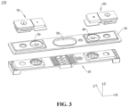
- FIG. 3 is a schematic exploded structural view of the end cover assembly 120 illustrated in FIG. 2
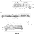
- FIG. 4 is a schematic cross-sectional structural view of the end cover assembly 120 illustrated in FIG. 2 , taken along line I-I.
- Taken along line I-I refers to cut along a plane where line I-I is positioned. Similar illustrations hereinafter may be interpreted in the same manner.
- the end cover assembly 120 includes a lower plastic member 10, a top cover 20, an explosion-proof valve 30, a positive-electrode deformation member 40, a negative-electrode deformation member 50, a positive-electrode unit 60, and a negative-electrode unit 70.
- the top cover 20 is mounted on a top side of the lower plastic member 10.
- the explosion-proof valve 30, the positive-electrode deformation member 40, and the negative-electrode deformation member 50 are all mounted to the top cover 20.
- the positive-electrode deformation member 40 and the negative-electrode deformation member 50 are positioned at two opposite sides of the explosion-proof valve 30, respectively.
- the positive-electrode deformation member 40 and the negative-electrode deformation member 50 are both spaced apart from the explosion-proof valve 30.
- the positive-electrode unit 60 and the negative-electrode unit 70 are both mounted to the top cover 20, and are positioned at opposite sides of the explosion-proof valve 30, respectively.
- the positive-electrode unit 60 and the positive-electrode deformation member 40 are positioned at the same side of the explosion-proof valve 30.
- the positive-electrode unit 60 covers the positive-electrode deformation member 40.
- the negative-electrode unit 70 and the negative-electrode deformation member 50 are positioned at the same side of the explosion-proof valve 30.
- the negative-electrode unit 70 covers the negative-electrode deformation member 50.
- Both the positive-electrode deformation member 40 and the negative-electrode deformation member 50 are configured to deform in response to an increase in a pressure inside the energy storage apparatus 100.
- a gas pressure inside the energy storage apparatus 100 exceeds a preset pressure threshold value
- the positive-electrode deformation member 40 can deform to be in contact with a conductive block of the positive-electrode unit 60 so that the positive-electrode unit 60 is short-circuited externally
- the negative-electrode deformation member 50 can deform to be in contact with a conductive block of the negative-electrode unit 70 so that the negative-electrode unit 70 is short-circuited externally.
- a large short-circuit current is generated to cause a phenomenon of fusing and top-cutting at the positive-electrode deformation member 40 and a bottom of the conductive block of the positive-electrode unit 60 so that the positive-electrode deformation member 40 is open-circuited with the conductive block of the positive-electrode unit 60
- a large short-circuit current is generated to cause a phenomenon of fusing and top-cutting at the negative-electrode deformation member 50 and a bottom of the conductive block of the negative-electrode unit 70 so that the negative-electrode deformation member 50 is open-circuited with the conductive block of the negative-electrode unit 70.
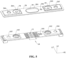
- FIG. 5 is a schematic structural view illustrating the lower plastic member 10, the top cover 20, the explosion-proof valve 30, the positive-electrode deformation member 40, and the negative-electrode deformation member 50 of the end cover assembly 120 illustrated in FIG. 3 .
- the lower plastic member 10 includes an explosion-proof grid 11.
- the explosion-proof grid 11 extends through a top surface (no reference number is illustrated) of the lower plastic member 10 and a bottom surface (no reference number is illustrated) of the lower plastic member 10.
- the explosion-proof grid 11 is positioned in the middle of the lower plastic member 10.
- the lower plastic member 10 defines a first electrolyte injection hole 101, a first avoidance groove 102, a second avoidance groove 103, a third mounting hole 104, and a fourth mounting hole 105.
- the first electrolyte injection hole 101 extends through the lower plastic member 10 in a thickness direction of the lower plastic member 10 (i.e., the Z-axis direction as illustrated).
- the first electrolyte injection hole 101 is positioned in the middle of the lower plastic member 10, is positioned at the right side of the explosion-proof grid 11, and is spaced apart from the explosion-proof grid 11.
- the first electrolyte injection hole 101 is a circular hole. In other embodiments, the first electrolyte injection hole 101 may also be a square hole or other irregular holes.
- the first avoidance groove 102 and the second avoidance groove 103 are defined at two opposite sides of the explosion-proof grid 11, respectively.
- the first avoidance groove 102 and the second avoidance groove 103 are both spaced apart from the explosion-proof grid 11.
- the first avoidance groove 102 is symmetrically defined with the second avoidance groove 103 about the explosion-proof grid 11.
- the first avoidance groove 102 is defined at the right side of the explosion-proof grid 11, is positioned at a side of the first electrolyte injection hole 101 facing away from the explosion-proof grid 11, and is spaced apart from the first electrolyte injection hole 101.
- the second avoidance groove 103 is defined at the left side of the first electrolyte injection hole 101.
- Both an opening of the first avoidance groove 102 and an opening of the second avoidance groove 103 are defined on the top surface (no reference number is illustrated) of the lower plastic member 10. Both the first avoidance groove 102 and the second avoidance groove 103 are recessed from the top surface of the lower plastic member 10 towards the bottom surface (no reference number is illustrated) of the lower plastic member 10, that is, recessed in the negative direction of the Z-axis as illustrated). Exemplarily, both the first avoidance groove 102 and the second avoidance groove 103 are circular grooves. In other embodiments, the first avoidance groove 102 and the second avoidance groove 103 may also be square grooves or other irregular grooves.
- the third mounting hole 104 is defined at a side of the first avoidance groove 102 facing away from the first electrolyte injection hole 101, and is spaced apart from the first avoidance groove 102.
- the fourth mounting hole 105 is defined at a side of the second avoidance groove 103 facing away from the explosion-proof grid 11, and is spaced apart from the second avoidance groove 103.
- the third mounting hole 104 is symmetrically defined with the fourth mounting hole 105 about the explosion-proof grid 11.
- both the third mounting hole 104 and the fourth mounting hole 105 extend through the lower plastic member 10 in the thickness direction of the lower plastic member 10.
- both the third mounting hole 104 and the fourth mounting hole 105 are circular holes, and in other embodiments, the third mounting hole 104 and the fourth mounting hole 105 may also be square holes or other irregular holes.
- the top cover 20 defines an explosion-proof hole 201, a second electrolyte injection hole 202, a fitting hole, and a mounting hole.
- the explosion-proof hole 201 extends through the top cover 20 in the thickness direction of the top cover 20 (i.e., the Z-axis direction as illustrated).
- the explosion-proof holes 201 are defined in the middle of the top cover 20.
- the explosion-proof hole 201 is in communication with the inside of the energy storage apparatus 100 through the explosion-proof grid 11.
- the explosion-proof hole 201 is an oval hole
- the second electrolyte injection hole 202 is a circular hole.
- the explosion-proof hole 201 may be a circular hole, a square hole, or other shaped holes.
- the second electrolyte injection hole 202 is defined in the middle of the top cover 20, is positioned at the right side of the explosion-proof hole 201, and is spaced apart from the explosion-proof hole 201. In an embodiment, the second electrolyte injection hole 202 extends through the top cover 20 in the thickness direction of the top cover 20. The second electrolyte injection hole 202 is in communication with the first electrolyte injection hole 101 of the lower plastic member 10. The electrolyte may be sequentially injected into the accommodation cavity of the housing 110 (as illustrated in FIG. 1 ) through the second electrolyte injection hole 202 of the top cover 20 and the first electrolyte injection hole 101 of the lower plastic member 10, thereby achieving injection of the electrolyte into the energy storage apparatus 100. Exemplarily, the second electrolyte injection hole 202 is a circular hole. In other embodiments, the second electrolyte injection hole 202 may be a square hole or other irregular holes.
- the fitting hole is defined at an edge of the top cover 20 and is spaced apart from the second electrolyte injection hole 202. In an embodiment, the fitting hole extends through the top cover 20 in the thickness direction of the top cover 20. In the embodiments, two fitting holes are defined and include a first mating hole 203 and a second mating hole 204. In the X-axis direction, the first mating hole 203 and the second mating hole 204 are defined at two opposite sides of the explosion-proof hole 201, respectively. The first mating hole 203 is symmetrically defined with the second mating hole 204 about the explosion-proof hole 201.
- the first mating hole 203 is defined at the right side of the explosion-proof hole 201, is positioned at a side of the second electrolyte injection hole 202 facing away from the explosion-proof hole 201, and is spaced apart from the explosion-proof hole 201.
- the second mating hole 204 is defined at the left side of the first electrolyte injection hole 101.
- the first mating hole 203 is in communication with the first avoidance groove 102.
- the second mating hole 204 is in communication with the second avoidance groove 103.
- both the first mating hole 203 and the second mating hole 204 are circular holes.
- the first mating hole 203 and the second mating hole 204 may also be square holes or other irregular holes.
- the mounting hole is positioned at the edge of the top cover 20 and is spaced apart from the fitting hole.
- the mounting hole extends through the top cover 20 in the thickness direction of the top cover 20.
- two mounting holes are defined and include a first mounting hole 205 and a second mounting hole 206.
- the mounting hole may be implemented as at least one of the first mounting hole 205 or the second mounting hole 206.
- the first mounting hole 205 is defined at a side of the first mating hole 203 facing away from the second electrolyte injection hole 202, and is spaced apart from the first mating hole 203.
- the second mounting hole 206 is defined at a side of the second mating hole 204 facing away from the explosion-proof hole 201, and is spaced apart from the second mating hole 204.
- the first mounting hole 205 is symmetrically defined with the second mounting hole 206 about the explosion-proof hole 201.
- the first mounting hole 205 is in communication with the third mounting hole 104 of the lower plastic member 10
- the second mounting hole 206 is in communication with the fourth mounting hole 105 of the lower plastic member 10.
- both the first mounting hole 205 and the second mounting hole 206 are circular holes.
- the first mounting hole 205 and the second mounting hole 206 may also be square holes or other irregular holes.
- the explosion-proof valve 30 is mounted in the explosion-proof hole 201 and is fixedly connected to a wall of the explosion-proof hole 201.
- the explosion-proof valve 30 may be fixedly connected to the wall of the explosion-proof hole 201 by welding, so that the explosion-proof valve 30 is mounted in the explosion-proof hole 201.
- the explosion-proof hole 201 is in communication with the inside and the outside of the energy storage apparatus 100, thus when a gas pressure inside the energy storage apparatus 100 is excessively high, the explosion-proof valve 30 will be broken under the effect of the gas pressure, so that gas inside the energy storage apparatus 100 can sequentially pass through the explosion-proof hole 201 and the explosion-proof grid 11 of the lower plastic member 10 and be discharged to the outside of the energy storage apparatus 100 in real time. Therefore, explosion of the energy storage apparatus 100 can be avoided, thereby improving the usage reliability of the energy storage apparatus 100.
- the positive-electrode deformation member 40 is mounted in the first mating hole 203 and fixedly connected to a wall of the first mating hole 203.
- the negative-electrode deformation member 50 is mounted in the second mating hole 204, and is fixedly connected to a wall of the second mating hole 204.
- the first avoidance groove 102 can avoid collision with the positive-electrode deformation member 40
- the second avoidance groove 103 can avoid collision with the negative-electrode deformation member 50.
- the positive-electrode deformation member 40 may be fixedly connected to the wall of the first mating hole 203 by welding, so that the positive-electrode deformation member 40 is mounted in the first mating hole 203.
- the negative-electrode deformation member 50 may be fixedly connected to the wall of the second mating hole 204 by welding, so that the negative-electrode deformation member 50 is mounted in the second mating hole 204.
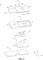
- FIG. 6 is a schematic exploded structural view of the positive-electrode unit 60 of the end cover assembly 120 illustrated in FIG. 3
- FIG. 7 is a schematic sectional structural view of a first upper plastic member 61 of the positive-electrode unit 60 illustrated in FIG. 6 , taken along line II-II.
- the upper plastic member may be implemented as at least one of the first upper plastic member 61 or a second upper plastic member 71.
- the positive-electrode unit 60 includes the first upper plastic member 61, a first conductive block 62, a first terminal post 63, a first sealing member 64, and a first connector 65.
- the first upper plastic member 61 is mounted to the top cover 20.
- the first upper plastic member 61 includes a first mounting portion 611 and a first mating portion 612.
- the first mating portion 612 is fixedly connected to a right side of the first mounting portion 611.
- the first mounting portion 611 defines a first fitting groove 613, a first avoidance hole 614, and a first identification through-hole 615. An opening of the first fitting groove 613 is defined on a right side surface (no reference number is illustrated) of the first mounting portion 611.
- the first fitting groove 613 is recessed from the right side surface of the first mounting portion 611 towards a left side surface (no reference number is illustrated) of the first mounting portion 611, that is, is recessed in the negative direction of the X-axis.
- the first fitting groove 613 has a first groove top surface 616 and a first groove bottom surface 617. In the Z-axis direction, the first groove top surface 616 is spaced apart and is disposed opposite to the first groove bottom surface 617.
- An opening of the first avoidance hole 614 is defined on a bottom surface (no reference number is illustrated) of the first mounting portion 611.
- the opening of the first avoidance hole 614 is positioned in the middle of the bottom surface of the first mounting portion 611.
- the first avoidance hole 614 is recessed from the bottom surface of the first mounting portion 611 towards the first fitting groove 613, that is, is recessed in the positive direction of the Z-axis as illustrated.
- the first avoidance hole 614 extends through the first groove bottom surface 617 of the first fitting groove 613, and is in communication with the first fitting groove 613.
- the first avoidance hole 614 is disposed opposite to the positive-electrode deformation member 40.
- the first avoidance hole 614 is a circular hole. In some other embodiments, the first avoidance hole 614 may also be a square hole or other irregular holes.
- An opening of the first identification through-hole 615 is defined on a top surface (no reference number is illustrated) of the first mounting portion 611.
- the opening of the first identification through-hole 615 is positioned in the middle of the top surface of the first mounting portion 611.
- the first identification through-hole 615 is recessed from the top surface of the first mounting portion 611 towards the first fitting groove 613, that is, is recessed in the negative direction of the Z-axis as illustrated.
- the first identification through-hole 615 extends through the first groove top surface 616 of the first fitting groove 613, and is in communication with the first fitting groove 613.
- the first identification through-hole 615 is of a cross-shape to identify that the polarity of the positive-electrode unit 60 is positive. In some other embodiments, the first identification through-hole 615 may also be of other shapes, as long as it can identify that the polarity of the positive-electrode unit 60 is positive.
- the first mounting portion 611 includes an identification portion 611a.
- the identification portion 611a is positioned at an end of the first mounting portion 611 facing away from the first mating portion 612 to identify the polarity of the positive-electrode unit 60.
- the identification portion 611a may be a chamfer.
- the identification portion 611a may serve as a fool proof structure of the first upper plastic member 61, preventing an operator from confusing the first upper plastic member 61 of the positive-electrode unit 60 and the second upper plastic member 71 of the negative-electrode unit 70.
- the first mating portion 612 defines a first mounting groove 618 and a first through hole 619.
- An opening of the first mounting groove 618 is defined on a top surface (no reference number is illustrated) of the first mating portion 612.
- the first mounting groove 618 is recessed from the top surface of the first mating portion 612 towards a bottom surface (no reference number is illustrated) of the first mating portion 612, that is, is recessed in the negative direction of the Z-axis as illustrated.
- the first mounting groove 618 is in communication with the first fitting groove 613.
- the first mounting groove 618 has a groove bottom surface (no reference number is illustrated).
- the first through hole 619 extends through the first mating portion 612 in a thickness direction of the first mating portion 612. In an embodiment, an opening of the first through hole 619 is defined on the bottom surface of the first mating portion 612. The first through hole 619 is recessed from the bottom surface of the first mating portion 612 towards the first mounting groove 618, that is, is recessed in the positive direction of the Z-axis as illustrated. The first through hole 619 extends through the groove bottom surface of the first mounting groove 618, and is in communication with the first mounting groove 618. The first through hole 619 is in communication with the first mounting hole 205 of the top cover 20. Exemplarily, the first through hole 619 is a circular hole. In some other embodiments, the first through hole 619 may also be a square hole or other irregular holes.
- FIG. 8 is a schematic structural view of the first conductive block 62 of the positive-electrode unit 60 illustrated in FIG. 6 , viewed from another direction.
- the first conductive block 62 is mounted to the first upper plastic member 61.
- the first conductive block 62 may be made of aluminum.
- the first conductive block 62 includes a first extension portion 621 and a first welding portion 622.
- the first welding portion 622 is fixedly connected to a right side of the first extension portion 621.
- the first extension portion 621 includes a first top surface 623 and a first bottom surface 624 opposite to the first top surface 623. Exemplarily, both the first top surface 623 and the first bottom surface 624 are flat surfaces.
- the first extension portion 621 is mounted in the first fitting groove 613 and covers the first avoidance hole 614 of the first upper plastic member 61 and the first identification through-hole 615 of the first upper plastic member 61.
- the first extension portion 621 is in interference fit with the first fitting groove 613.
- the first top surface 623 of the first extension portion 621 abuts against the first groove top surface 616 of the first fitting groove 613 and covers the first identification through-hole 615 of the first upper plastic member 61.
- the first bottom surface 624 of the first extension portion 621 abuts against the first groove bottom surface 617 of the first fitting groove 613 and covers the first avoidance hole 614 of the first upper plastic member 61.
- a color of the first extension portion 621 is different from a color of the first mounting portion 611.
- the first extension portion 621 is in a bright silver color
- the first mounting portion 611 is in a black color.
- the first top surface 623 of the first extension portion 621 exposes through the first identification through-hole 615, so that a pronounced color contrast is created to form a positive polarity symbol "+", thereby identifying the polarity of the positive-electrode unit 60.
- the first extension portion 621 is in interference fit with the first fitting groove 613, thus the first top surface 623 of the first extension portion 621 is in close contact with the first groove top surface 616 of the first fitting groove 613 without a gap. This prevents the first identification through-hole 615 from being suspended to form a shadow on the first top surface 623 of the first extension portion 621, thereby improving legibility of the polarity identification.
- a thickness of the first welding portion 622 is greater than a thickness of the first extension portion 621.
- the first welding portion 622 includes a second top surface 625 and a second bottom surface 626 opposite the second top surface 625.
- the second bottom surface 626 of the first welding portion 622 is flush with the first bottom surface 624 of the first extension portion 621.
- the second top surface 625 of the first welding portion 622 protrudes relative to the first top surface 623 of the first extension portion 621.
- the first welding portion 622 defines a first fitting hole 627.
- the first fitting hole 627 is positioned in the middle of the first welding portion 622.
- the first fitting hole 627 extends through the first welding portion 622 in a thickness direction of the first welding portion 622 (i.e., the Z-axis direction as illustrated).
- the first fitting hole 627 is a circular hole, and in other embodiments, the first fitting hole 627 may also be a square hole or other irregular holes.
- first welding portion 622 is provided with a first protruding ring 622a.
- the first protruding ring 622a is disposed on the first welding portion 622 and surrounds an inner wall of the first fitting hole 627.
- the first protruding ring 622a is disposed on the second bottom surface 626 of the first welding portion 622 and protrudes from the second bottom surface 626 of the first welding portion 622 in a direction facing away from the second top surface 625.
- a bottom surface of the first protruding ring 622a is a flat surface.
- the first protruding ring 622a is in an annular shape and is coaxial with the first fitting hole 627. In some other embodiments, the first protruding ring 622a may also be in a rectangular ring shape or other irregular ring shapes.
- a ratio of a thickness w of the first protruding ring 622a to a height h of the first protruding ring 622a ranges from 0.2 to 0.8. This can ensure that the first protruding ring 622a has enough rigidity, so that the first protruding ring 622a can abut against the first upper plastic member 61, thereby tightly pressing the first sealing member 64.
- the height h of the first protruding ring 622a ranges from 0.1mm to 1.2mm to ensure that the first protruding ring 622a is sufficiently tall to effectively abut against the first upper plastic member 61.
- the thickness w of the first protruding ring 622a ranges 0.2 mm to 2.4 mm to ensure that the first protruding ring 622a has a sufficient region in contact with the first upper plastic member 61, thereby allowing a more uniform abutment against the first upper plastic member 61.
- the first welding portion 622 is disposed in the first mounting groove 618.
- the first protruding ring 622a abuts against the first upper plastic member 61.
- the first fitting hole 627 of the first welding portion 622 is in communication with the first through hole 619 of the first upper plastic member 61.
- the first protruding ring 622a of the first welding portion 622 abuts against a groove bottom surface of the first mounting groove 618.
- the second top surface 625 of the first welding portion 622 protrudes relative to the top surface of the first mounting portion 611 of the first upper plastic member 61.
- a peripheral surface of the first welding portion 622 is spaced apart from a surface of the first mounting portion 611 facing towards the first mating portion 612 (i.e., the right side surface of the first mounting portion 611). It may be understood that, the second top surface 625 of the first welding portion 622 protrudes relative to the top surface of the first mounting portion 611 of the first upper plastic member 61.
- the first welding portion 622 includes a first fitting portion 628 and a first connecting portion 629.
- the first connecting portion 629 is disposed on a top side of the first fitting portion 628.
- the first connecting portion 629 extends outwards relative to a peripheral surface of the first fitting portion 628 to form a protruding ring.
- a bottom surface of the first fitting portion 628 serves as the second bottom surface 626 of the first welding portion 622.
- a top surface of the first connecting portion 629 serves as the second top surface 625 of the first welding portion 622.
- the first fitting hole 627 extends through the first fitting portion 628 and the first connecting portion 629.
- the first protruding ring 622a is disposed on a surface of the first fitting portion 628 facing away from the first connecting portion 629 (i.e., the bottom surface of the first fitting portion 628).
- the first fitting portion 628 is disposed in the first mounting groove 618.
- the first connecting portion 629 protrudes relative to the first mounting groove 618 and abuts against the top surface of the first mating portion 612 of the first upper plastic member 61.
- a peripheral surface of the first connecting portion 629 is spaced apart from and opposite to the right side surface of the first mounting portion 611 of the first upper plastic member 61. It may be understood that a gap between the right side surface of the first mounting portion 611 of the first upper plastic member 61 and the peripheral surface of the first connecting portion 629 may serve as an error accommodating region.
- the first connecting portion 629 may also be flush with the opening of the first mounting groove 618, or the first connecting portion 629 may be recessed relative to the first mounting groove 618.
- the peripheral surface of the first fitting portion 628 is covered by a side wall of the first mounting groove 618. That is, the first mating portion 612 of the first upper plastic member 61 covers the peripheral surface of the first fitting portion 628.
- a distance between the first connecting portion 629 and the top cover 20 improves the insulation performance between the first connecting portion 629 and the top cover 20, and increases a creep age distance between the first conductive block 62 and the top cover 20, thereby avoiding an arc short circuit between the first conductive block 62 and the top cover 20.
- the first terminal post 63 includes a first flange portion 631 and a first post portion 632.
- the first post portion 632 is disposed on a top side of the first flange portion 631.
- the first post portion 632 extends through the third mounting hole 104 of the lower plastic member 10, the first mounting hole 205 of the top cover 20, the first through hole 619 of the first upper plastic member 61, the first protruding ring 622a of the first conductive block 62, and the first fitting hole 627 of the first conductive block 62, and is fixedly connected to the first conductive block 62.
- the first post portion 632 is fixedly connected to a wall of the first fitting hole 627.
- the first post portion 632 may be fixedly connected to the wall of the first fitting hole 627 of the first conductive block 62 by welding.
- the first flange portion 631 may be positioned inside the lower plastic member 10, and a top surface of the first flange portion 631 may abut against the lower plastic member 10.
- the first sealing member 64 includes a first sealing portion 641 and a first secondary sealing portion 642.
- the first secondary sealing portion 642 is disposed at a bottom of the first sealing portion 641 and surrounds the first sealing portion 641.
- the first sealing member 64 is sleeved on the first post portion 632 of the first terminal post 63 and is clamped between the first post portion 632 and a wall of the first mounting hole 205 of the top cover 20.
- a top surface (no reference number is illustrated) of the first sealing member 64 abuts against a bottom surface of the first upper plastic member 61.
- a bottom surface (no reference number is illustrated) of the first sealing member 64 abuts against the top surface of the first flange portion 631 of the first terminal post 63.
- the first sealing portion 641 of the first sealing member 64 is clamped between the first post portion 632 of the first terminal post 63 and the wall of the first mounting hole 205 of the top cover 20.
- a surface of the first sealing portion 641 facing away from the first secondary sealing portion 642 i.e., a top surface of the first sealing portion 641 abuts against the bottom surface of the first upper plastic member 61.
- a surface of the first secondary sealing portion 642 facing away from the first sealing portion 641 i.e., a bottom surface of the first secondary sealing portion 642 abuts against the top surface of the first flange portion 631 of the first terminal post 63.
- the first sealing member 64 not only can ensure stability of assembly between the first terminal post 63 and the lower plastic member 10 and stability of assembly between the first terminal post 63 and the top cover 20, but also can prevent the first terminal post 63 from being in direct electrical contact with the top cover 20, thereby realizing insulation between the first terminal post 63 and the top cover 20.
- the first protruding ring 622a of the first conductive block 62 abuts against the first mating portion 612 of the first upper plastic member 61, so that the first mating portion 612 of the first upper plastic member 61 abuts against the top surface of the first sealing member 64, and the first flange portion 631 of the first terminal post 63 abuts against the bottom surface of the first sealing member 64.
- the first sealing member 64 is clamped between the first upper plastic member 61 and the first flange portion 631 of the first terminal post 63, thereby ensuring the assembling stability of the first sealing member 64, improving the sealing performance between the first terminal post 63 and the top cover 20, ensuring the sealing performance of the energy storage apparatus 100, and improving the assembly yield of the energy storage apparatus 100.
- the first connector 65 is mounted at an inner side of the lower plastic member 10 and positioned at a side of the first flange portion 631 of the first terminal post 63 facing away from the first post portion 632.
- one end of the first connector 65 is electrically connected to the first flange portion 631 of the first terminal post 63, and the other end of the first connector 65 is electrically connected to a positive tab of the jelly-roll.
- the first connector 65 may be electrically connected to the first flange portion 631 of the first terminal post 63 and/or the positive tab of the jelly-roll by welding.
- FIG. 9 is a schematic exploded structural view of the negative-electrode unit 70 of the end cover assembly 120 illustrated in FIG. 3 .
- the negative-electrode unit 70 includes a second upper plastic member 71, a second conductive block 72, a second terminal post 73, a second sealing member 74, and a second connector 75.
- a structure of each component in the negative-electrode unit 70 an assembly relationship between a component and another component, an assembly relationship between a component and the lower plastic member 10, and an assembly relationship between a component and the top cover 20, reference may be made to the foregoing relevant illustration of the positive-electrode unit 60, and details are not repeatedly described herein.
- the conductive block may be implemented as at least one of the first conductive block 62 or the second conductive block 72.
- the terminal post may be implemented as at least one of the first terminal post 63 or the second terminal post 73.
- the sealing member may be implemented as at least one of the first sealing member 64 or the second sealing member 74.
- the second upper plastic member 71 is mounted at a top side of the top cover 20, is positioned at a left side of the first upper plastic member 61, and is spaced apart from the first upper plastic member 61.
- the second upper plastic member 71 includes a second mounting portion 711 and a second mating portion 712.
- the second mating portion 712 is fixedly connected to a left side of the second mounting portion 711.
- the second mounting portion 711 defines a second fitting groove 713, a second avoidance hole 714, and a second identification through-hole 715.
- the second mating portion 712 defines a second mounting groove 718 and a second through hole 719.
- the second through hole 719 is in communication with the second mounting hole 206 of the top cover 20.
- the second fitting groove 713 has a second groove top surface 716 and a second groove bottom surface 717.
- the second avoidance hole 714 is disposed opposite to the negative-electrode deformation member 50.
- the second identification through-hole 715 is in a rectangular shape to identify that the polarity of the negative-electrode unit 70 is negative. In some other embodiments, the second identification through-hole 715 may also of other shapes, as long as the second identification through-hole 715 can identify that the polarity of the negative-electrode unit 70 is negative.
- the mounting portion may be implemented as at least one of the first mounting portion 611 or the second mounting portion 711.
- the mating portion may be implemented as at least one of the first mating portion 612 or the second mating portion 712.
- the fitting groove may be implemented as at least one of the first fitting groove 613 or the second fitting groove 713.
- the identification through-hole may be implemented as at least one of the first identification through-hole 615 or the second identification through-hole 715.
- the through hole may be implemented as at least one of the first through hole 619 or the second through hole 719.
- the mounting groove may be implemented as at least one of the first mounting groove 618 or the second mounting groove 718.
- the groove top surface may be implemented as at least one of the first groove top surface 616 or the second groove top surface 716.
- the groove bottom surface may be implemented as at least one of the first groove bottom surface 617 or the second groove bottom surface 717.
- the second mounting portion 711 may further include an identification portion (not illustrated).
- the identification portion is configured to identify the polarity of the negative-electrode unit 70.
- the identification portion of the second mounting portion 711 is different from the identification portion 611a of the first mounting portion 611, so that an operator may distinguish the second upper plastic member 71 of the negative-electrode unit 70 from the first upper plastic member 61 of the positive-electrode unit 60.
- the second conductive block 72 is mounted to the second upper plastic member 71.
- the second conductive block 72 includes a second extension portion 721 and a second welding portion 722.
- the second welding portion 722 is fixedly connected to a left side of the second extension portion 721.
- the second welding portion 722 is provided with a second protruding ring 722a.
- the second protruding ring 722a is disposed on the second welding portion 722 and surrounds an inner wall of the second fitting hole 727.
- the second protruding ring 722a is disposed on a fourth bottom surface 726 of the second welding portion 722.
- the second protruding ring 722a protrudes from the fourth bottom surface 726 of the second welding portion 722 towards a direction facing away from a fourth top surface 725.
- the fitting hole may be implemented as at least one of the first fitting hole 627 or the second fitting hole 727.
- the protruding ring may be implemented as at least one of the first protruding ring 622a or the second protruding ring 722a.
- the extension portion may be implemented as at least one of the first extension portion 621 or the second extension portion 721.
- the welding portion may be implemented as at least one of the first welding portion 622 or the second welding portion 722.
- the second extension portion 721 is mounted in the second fitting groove 713.
- the second welding portion 722 is disposed in the second mounting groove 718.
- the second fitting hole 727 of the second welding portion 722 is in communication with the second through hole 719 of the second mating portion 712.
- the second protruding ring 722a of the second welding portion 722 abuts against a groove bottom surface of the second mounting groove 718.
- the second extension portion 721 is in interference fit with the second fitting groove 713.
- a third top surface 723 of the second extension portion 721 abuts against the second groove top surface 716 of the second fitting groove 713, and covers the second identification through-hole 715 of the second upper plastic member 71.
- a third bottom surface 724 of the second extension portion 721 abuts against the second groove bottom surface 717 of the second fitting groove 713, and covers the second avoidance hole 714 of the second upper plastic member 71.
- a color of the second extension portion 721 is different from a color of the second mounting portion 711.
- the second extension portion 721 is in a bright silver color
- the second mounting portion 711 is in a black color.
- the third top surface 723 of the second extension portion 721 exposes through the second identification through-hole 715, so that a pronounced color contrast is created to form a negative polarity symbol "-", thereby identifying the polarity of the negative-electrode unit 70.
- both the positive-electrode deformation member 40 and the negative-electrode deformation member 50 are driven to flip by the gas pressure.
- the positive-electrode deformation member 40 extends through the first avoidance hole 614 and comes into contact with the first welding portion 622 so that the top cover 20 is electrically connected to the first conductive block 62
- the negative-electrode deformation member 50 extends through the second avoidance hole 714 and comes into contact with the second welding portion 722 so that the top cover 20 is electrically connected to the second conductive block 72.
- the positive-electrode unit 60 and the negative-electrode unit 70 are conducted to generate a short circuit, rendering the energy storage apparatus 100 unable to operate properly. Therefore, the gas pressure inside the energy storage apparatus 100 cannot be further increased, thereby improving the usage reliability of the energy storage apparatus 100.
- the second welding portion 722 includes a second fitting portion 728 and a second connecting portion 729.
- the first connecting portion 729 is disposed on a top side of the second fitting portion 728.
- the second connecting portion 729 extends outwards relative to a peripheral surface of the second fitting portion 728 to form a protruding ring.
- the second fitting portion 728 is mounted in the second mounting groove 718, and the second connecting portion 729 protrudes relative to the second mounting groove 718 and abuts against a top surface of the second mating portion 712 of the second upper plastic member 71.
- the peripheral surface of the second fitting portion 728 is covered by a side wall of the second mounting groove 718.
- the second mating portion 712 of the second upper plastic member 71 covers the peripheral surface of the second fitting portion 728.
- a distance between the second connecting portion 729 and the top cover 20 improves the insulation performance between the second connecting portion 729 and the top cover 20, and increases a creep age distance between the second conductive block 72 and the top cover 20, thereby avoiding an arc short circuit between the second conductive block 72 and the top cover 20.
- the fitting portion may be implemented as at least one of the first fitting portion 628 or the second fitting portion 728.
- the connecting portion may be implemented as at least one of the first connecting portion 629 or the second connecting portion 729.
- the second terminal post 73 includes a second flange portion 731 and a second post portion 732.
- the second post portion 732 is fixedly connected to a top side of the second flange portion 731.
- the second post portion 732 extends through the fourth mounting hole 105 of the lower plastic member 10, the second mounting hole 206 of the top cover 20, the second through hole 719 of the second upper plastic member 71, the second protruding ring 722a of the second conductive block 72, and the second fitting hole 727 of the second conductive block 72.
- the second post portion 732 is fixedly connected to a wall of the second fitting hole 727 of the second conductive block 72.
- the flange portion may be implemented as at least one of the first flange portion 631 or the second flange portion 731.
- the post portion may be implemented as at least one of the first post portion 632 or the second post portion 732.
- the second sealing member 74 includes a second sealing portion 741 and a second secondary sealing portion 742.
- the second secondary sealing portion 742 is fixedly connected to a bottom of the second sealing portion 741 and surrounds the second sealing portion 741.
- a top surface (no reference number is illustrated) of the second sealing portion 741 abuts against a bottom surface of the second upper plastic member 71.
- a bottom surface (no reference number is illustrated) of the second sealing portion 74 abuts against a top surface of the second flange portion 731 of the second terminal post 73.
- Part of the second sealing portion 741 is clamped between the second post portion 732 of the second terminal post 73 and a wall of the second mounting hole 206 of the top cover 20.
- the sealing portion may be implemented as at least one of the first sealing portion 641 or the second sealing portion 741.
- the secondary sealing portion may be implemented as at least one of the first secondary sealing portion 642 or the second secondary sealing portion 742.
- the second connector 75 is mounted at an inner side of the lower plastic member 10 and positioned at a side of the second flange portion 731 of the second terminal post 73 facing away from the second post portion 732.
- one end of the second connector 75 is electrically connected to the second flange portion 731 of the second terminal post 73, and the other end of the second connector 75 is electrically connected to a negative tab of the j elly-roll.
- the second connector 75 may be electrically connected to the second flange portion 731 of the second terminal post 73 and/or the positive tab of the jelly-roll by welding.
- the protruding ring of the conductive block abuts against the upper plastic member, so that the upper plastic member abuts against the top surface of the sealing member.
- the flange portion of the terminal post abuts against the bottom surface of the sealing member.
- the sealing member is clamped between the upper plastic member and the terminal post. In this way, the assembly stability of the sealing member is ensured, the sealing performance between the terminal post and the top cover is enhanced, and the sealing performance of the jelly-roll is ensured.
- the energy storage apparatus 100 may also be an apparatus that has a function of storing power, such as a battery module, a battery pack, or a battery system.
- the energy storage apparatus 100 is a battery pack.
- the energy storage apparatus 100 includes multiple jelly-rolls and multiple connecting sheets. Each connecting sheet is electrically connected between two jelly-rolls.
- the jelly-roll may have structures illustrated in the energy storage apparatus 100 described in the above embodiments. In this case, the multiple jelly-rolls may be connected in series, one end of each connection sheet is electrically connected to a positive electrode assembly of one jelly-roll, and another end of each connection sheet is electrically connected to a negative electrode assembly of another j elly-roll.
- the multiple jelly-rolls may also be connected in parallel, part of the connecting sheets is electrically connected between the positive electrode assemblies of the two jelly-rolls, and part of the connecting sheets is electrically connected between the negative electrode assemblies of the two jelly-rolls.
- the connecting sheet may be an aluminum bar. It may be noted that, part of the jelly-rolls may also be arranged in series, and part of the jelly-rolls may be arranged in parallel. The embodiments of the disclosure do not specifically limit a connection manner of the multiple jelly-rolls in the battery pack.
- the electricity-consumption device (1) includes the energy storage apparatus 100.
- the energy storage apparatus 100 is configured to power the electricity-consumption device (1).
- the electricity-consumption device (1) may be a new energy vehicle, an electricity storage station, a server, and other devices requiring electricity.
Landscapes
- Chemical & Material Sciences (AREA)
- Chemical Kinetics & Catalysis (AREA)
- Electrochemistry (AREA)
- General Chemical & Material Sciences (AREA)
- Inorganic Chemistry (AREA)
- Connection Of Batteries Or Terminals (AREA)
- Sealing Battery Cases Or Jackets (AREA)
Abstract
Description
- The disclosure relates to the field of energy storage technologies, and in particular, to an end cover assembly, an energy storage apparatus, and an electricity-consumption device.
- In existing energy storage apparatuses (for example, secondary batteries), a sealing member, an upper plastic member, and a lower plastic member are generally arranged between a terminal post and a top cover to achieve sealing. However, the terminal post and a conductive block will be subjected to a relatively large external force during riveting, and the sealing member easily loosens, thereby reducing the sealing performance between the terminal post and the top cover, and lowing a production yield of the energy storage apparatuses.
- According to a first aspect, an end cover assembly applicable to a battery cell is provided in the disclosure. The end cover assembly includes a top cover, an upper plastic member, a conductive block, a terminal post, and a sealing member. The top cover defines a mounting hole. The mounting hole extends through the top cover in a thickness direction of the top cover. The upper plastic member is mounted on the top cover. The upper plastic member defines a through hole extending through the upper plastic member in a thickness direction of the upper plastic member and being in communication with the mounting hole. The conductive block is mounted on the upper plastic member. The conductive block defines a fitting hole. The fitting hole extends through the conductive block in a thickness direction of the conductive block and is in communication with the through hole. The conductive block includes a protruding ring. The protruding ring is disposed on the conductive block and surrounds an inner wall of the fitting hole. The protruding ring abuts against the upper plastic member. The terminal post includes a flange portion and a post portion. The post portion is disposed on a top side of the flange portion. The post portion extends through the mounting hole, the through hole, and the fitting hole and is fixedly connected to the conductive block. The sealing member is sleeved on the post portion and clamped between the post portion and a wall of the mounting hole. A top surface of the sealing member abuts against a bottom surface of the upper plastic member, and a bottom surface of the sealing member abuts against a top surface of the flange portion.
- According to a second aspect, an energy storage apparatus is provided in the disclosure. The energy storage apparatus includes a housing and the end cover assembly provided in any one of the above embodiments, the end cover assembly is mounted on a top side of the housing.
- According to a third aspect, an electricity-consumption device is provided in the disclosure. The electricity-consumption device includes the above-mentioned energy storage apparatus, and the energy storage apparatus is configured to power the electricity-consumption device.
- To describe the technical solutions in the embodiments of the disclosure more clearly, the following describes the accompanying drawings required for describing the embodiments of the disclosure.
-
FIG. 1 is a schematic structural view of an energy storage apparatus according to embodiments of the disclosure. -
FIG. 2 is a schematic structural view of an end cover assembly of the energy storage apparatus illustrated inFIG. 1 . -
FIG. 3 is a schematic exploded structural view of the end cover assembly illustrated inFIG. 2 . -
FIG. 4 is a schematic cross-sectional structural view of the end cover assembly illustrated inFIG. 2 , taken along line I-I. -
FIG. 5 is a schematic structural view illustrating a lower plastic member, a top cover, an explosion-proof valve, a positive-electrode deformation member, and a negative-electrode deformation member of the end cover assembly illustrated inFIG. 3 . -
FIG. 6 is a schematic exploded structural view of a positive-electrode unit of the end cover assembly illustrated inFIG. 3 . -
FIG. 7 is a schematic cross-sectional structural view of a first upper plastic member of the positive-electrode unit illustrated inFIG. 6 , taken along line II-II. -
FIG. 8 is a schematic structural view of a first conductive block of the positive-electrode unit illustrated inFIG. 6 , viewed from another direction. -
FIG. 9 is a schematic exploded structural view of a negative-electrode unit of the end cover assembly illustrated inFIG. 3 . -
FIG. 10 is a schematic diagram of an electricity-consumption device according to embodiments of the disclosure. - Reference numbers in the accompanying drawings are described as follows:
energy storage apparatus 100,housing 110,end cover assembly 120, lowerplastic member 10,top cover 20, explosion-proof valve 30, positive-electrode deformation member 40, negative-electrode deformation member 50, positive-electrode unit 60, negative-electrode unit 70, explosion-proof grid 11, firstelectrolyte injection hole 101,first avoidance groove 102,second avoidance groove 103,third mounting hole 104,fourth mounting hole 105, explosion-proof hole 201, secondelectrolyte injection hole 202,first mating hole 203,second mating hole 204,first mounting hole 205,second mounting hole 206, first upperplastic member 61, firstconductive block 62,first terminal post 63,first sealing member 64,first connector 65,first mounting portion 611,first mating portion 612,first fitting groove 613,first avoidance hole 614, first identification through-hole 615, first groovetop surface 616, firstgroove bottom surface 617,identification portion 611a,first mounting groove 618, first throughhole 619,first extension portion 621,first welding portion 622, firsttop surface 623,first bottom surface 624,first protruding ring 622a, secondtop surface 625,second bottom surface 626,first fitting hole 627,first fitting portion 628, first connectingportion 629,first flange portion 631,first post portion 632,first sealing portion 641, firstsecondary sealing portion 642, second upperplastic member 71, secondconductive block 72,second terminal post 73,second sealing member 74,second connector 75,second mounting portion 711,second mating portion 712,second fitting groove 713,second avoidance hole 714, second identification through-hole 715, second groovetop surface 716, secondgroove bottom surface 717,second mounting groove 718, second throughhole 719,second extension portion 721,second welding portion 722, thirdtop surface 723,third bottom surface 724,second protruding ring 722a, fourthtop surface 725,fourth bottom surface 726,second fitting hole 727,second fitting portion 728, second connectingportion 729,second flange portion 731,second post portion 732,second sealing portion 741, secondsecondary sealing portion 742, electricity-consumption device 1. - The following clearly and completely describes the technical solutions in the embodiments of the disclosure with reference to the accompanying drawings in the embodiments of the disclosure.
- An end cover assembly, an energy storage apparatus, and an electricity-consumption device are provided in the disclosure to achieve an improved production yield.
- According to a first aspect, an end cover assembly applicable to a battery cell is provided in the disclosure. The end cover assembly includes a top cover, an upper plastic member, a conductive block, a terminal post, and a sealing member. The top cover defines a mounting hole. The mounting hole extends through the top cover in a thickness direction of the top cover. The upper plastic member is mounted on the top cover. The upper plastic member defines a through hole extending through the upper plastic member in a thickness direction of the upper plastic member and being in communication with the mounting hole. The conductive block is mounted on the upper plastic member. The conductive block defines a fitting hole. The fitting hole extends through the conductive block in a thickness direction of the conductive block and is in communication with the through hole. The conductive block includes a protruding ring. The protruding ring is disposed on the conductive block and surrounds an inner wall of the fitting hole. The protruding ring abuts against the upper plastic member after assembly. The terminal post includes a flange portion and a post portion. The post portion is disposed on a top side of the flange portion. The post portion extends through the mounting hole, the through hole, and the fitting hole and is fixedly connected to the conductive block. The sealing member is sleeved on the post portion and clamped between the post portion and a wall of the mounting hole. A top surface of the sealing member abuts against a bottom surface of the upper plastic member, and a bottom surface of the sealing member abuts against a top surface of the flange portion.
- In embodiments of the disclosure, a ratio of a thickness of the protruding ring to a height of the protruding ring ranges from 0.2 to 0.8.
- In embodiments of the disclosure, a height of the protruding ring ranges from 0.1 mm to 1.2 mm.
- In embodiments of the disclosure, a thickness of the protruding ring ranges from 0.2 mm to 2.4 mm.
- In embodiments of the disclosure, the sealing member includes a sealing portion and a secondary sealing portion. The secondary sealing portion is positioned on a bottom of the sealing portion and surrounds the sealing portion. The sealing portion is sleeved on the post portion and clamped between the post portion and the wall of the mounting hole of the top cover.
- A surface of the sealing portion that faces away from the secondary sealing portion abuts against the upper plastic member. A surface of the secondary sealing portion that faces away from the sealing portion abuts against the top surface of the flange portion.
- In embodiments of the disclosure, the conductive block includes a fitting portion and a connecting portion. The connecting portion is disposed on a top side of the fitting portion and extends outwards relative to a peripheral surface of the fitting portion to form the protruding ring. The upper plastic member covers the peripheral surface of the fitting portion.
- In embodiments of the disclosure, the upper plastic member defines a mounting groove, and the fitting portion is received in the mounting groove.
- In embodiments of the disclosure, the through hole is in communication with the mounting groove, the fitting hole extends through the fitting portion and the connecting portion, and the protruding ring is disposed on a surface of the fitting portion away from the connecting portion.
- In embodiments of the disclosure, the upper plastic member includes a mounting portion and a mating portion fixedly connected to one side of the mounting portion. The mounting portion defines a fitting groove and an identification through-hole. An opening of the fitting groove is defined on a surface of the mounting portion facing towards the mating portion. The fitting groove is in communication with the mounting groove. An opening of the identification through-hole is defined on a top surface of the mounting portion, and the identification through-hole is in communication with the fitting groove. The mating portion defines the mounting groove and the through hole. The conductive block includes an extension portion and a welding portion. The welding portion is fixedly connected to one side of the extension portion. The extension portion is mounted to the fitting groove. A top surface of the extension portion covers the identification through-hole. The extension portion is different from the mounting portion in color. The welding portion includes the fitting portion and the connecting portion. The welding portion is received in the mounting groove.
- In embodiments of the disclosure, the fitting groove includes a groove top surface and a groove bottom surface opposite the groove top surface. The top surface of the extension portion abuts against the groove top surface. A bottom surface of the extension portion abuts against the groove bottom surface.
- In embodiments of the disclosure, a top surface of the welding portion protrudes relative to the top surface of the mounting portion.
- In embodiments of the disclosure, a surface of the mounting portion facing towards the mating portion is spaced from an outer peripheral surface of the welding portion.
- In embodiments of the disclosure, the end cover assembly includes a positive-electrode unit and a negative-electrode unit. The positive-electrode unit and the negative-electrode unit are both mounted to the top cover and are arranged at intervals. The negative-electrode unit includes one upper plastic member, one conductive block, one terminal post, and one sealing member. The positive-electrode unit includes one upper plastic member, one conductive block, one terminal post, and one sealing member.
- According to a second aspect, an energy storage apparatus is provided in the disclosure. The energy storage apparatus includes a housing and the end cover assembly provided in any one of the above embodiments, the end cover assembly is mounted on a top side of the housing.
- According to a third aspect, an electricity-consumption device is provided in the disclosure. The electricity-consumption device includes the above-mentioned energy storage apparatus, and the energy storage apparatus is configured to power the electricity-consumption device.
-
FIG. 1 is a schematic structural view of anenergy storage apparatus 100 according to the embodiments of the disclosure. For ease of illustration, a length direction of theenergy storage apparatus 100 is defined as an X-axis direction, a width direction of theenergy storage apparatus 100 is defined as a Y-axis direction, a height direction of theenergy storage apparatus 100 is defined as a Z-axis direction. The X-axis direction, the Y-axis direction, and the Z-axis direction are perpendicular to each other. - The
energy storage apparatus 100 includes ahousing 110, a j elly-roll (not illustrated), and anend cover assembly 120. Thehousing 110 has an opening (not illustrated) and an accommodation cavity (not illustrated). The jelly-roll is accommodated in the accommodation cavity. The accommodation cavity is also configured for accommodating an electrolyte, and the jelly-roll is soaked in the electrolyte. Theend cover assembly 120 is mounted on a top side of thehousing 110 and seals the opening. Exemplarily, theenergy storage apparatus 100 may be a prismatic battery. In other embodiments, theenergy storage apparatus 100 may also be a cylindrical battery or other batteries. - It may be noted that, directional terms such as "top", "bottom", "left", and "right" in the disclosure are described with reference to orientations illustrated in
FIG. 1 . "Top" is defined as facing a positive direction of the Z-axis. "Bottom" is defined as facing a negative direction of the Z-axis. "Right" is defined as facing a positive direction of the X-axis. "Left" is defined as facing a negative direction of the X-axis. The above terms do not explicitly or implicitly indicate that apparatuses/devices or components referred to must have a certain orientation, be configured or operated in a certain orientation, and therefore cannot be understood as limitations on the disclosure. - As illustrated in
FIGs. 2 to 4 ,FIG. 2 is a schematic structural view of theend cover assembly 120 of theenergy storage apparatus 100 illustrated inFIG. 1 ,FIG. 3 is a schematic exploded structural view of theend cover assembly 120 illustrated inFIG. 2 , andFIG. 4 is a schematic cross-sectional structural view of theend cover assembly 120 illustrated inFIG. 2 , taken along line I-I. "Taken along line I-I" refers to cut along a plane where line I-I is positioned. Similar illustrations hereinafter may be interpreted in the same manner. - The
end cover assembly 120 includes alower plastic member 10, atop cover 20, an explosion-proof valve 30, a positive-electrode deformation member 40, a negative-electrode deformation member 50, a positive-electrode unit 60, and a negative-electrode unit 70. Thetop cover 20 is mounted on a top side of thelower plastic member 10. The explosion-proof valve 30, the positive-electrode deformation member 40, and the negative-electrode deformation member 50 are all mounted to thetop cover 20. The positive-electrode deformation member 40 and the negative-electrode deformation member 50 are positioned at two opposite sides of the explosion-proof valve 30, respectively. The positive-electrode deformation member 40 and the negative-electrode deformation member 50 are both spaced apart from the explosion-proof valve 30. The positive-electrode unit 60 and the negative-electrode unit 70 are both mounted to thetop cover 20, and are positioned at opposite sides of the explosion-proof valve 30, respectively. The positive-electrode unit 60 and the positive-electrode deformation member 40 are positioned at the same side of the explosion-proof valve 30. The positive-electrode unit 60 covers the positive-electrode deformation member 40. The negative-electrode unit 70 and the negative-electrode deformation member 50 are positioned at the same side of the explosion-proof valve 30. The negative-electrode unit 70 covers the negative-electrode deformation member 50. - Both the positive-
electrode deformation member 40 and the negative-electrode deformation member 50 are configured to deform in response to an increase in a pressure inside theenergy storage apparatus 100. When a gas pressure inside theenergy storage apparatus 100 exceeds a preset pressure threshold value, the positive-electrode deformation member 40 can deform to be in contact with a conductive block of the positive-electrode unit 60 so that the positive-electrode unit 60 is short-circuited externally, and the negative-electrode deformation member 50 can deform to be in contact with a conductive block of the negative-electrode unit 70 so that the negative-electrode unit 70 is short-circuited externally. As a result, a large short-circuit current is generated to cause a phenomenon of fusing and top-cutting at the positive-electrode deformation member 40 and a bottom of the conductive block of the positive-electrode unit 60 so that the positive-electrode deformation member 40 is open-circuited with the conductive block of the positive-electrode unit 60, and a large short-circuit current is generated to cause a phenomenon of fusing and top-cutting at the negative-electrode deformation member 50 and a bottom of the conductive block of the negative-electrode unit 70 so that the negative-electrode deformation member 50 is open-circuited with the conductive block of the negative-electrode unit 70. This can avoid an overcharging and explosion of theenergy storage apparatus 100, ensuring the safety and reliability of theenergy storage apparatus 100. - As illustrated in
FIG. 5, FIG. 5 is a schematic structural view illustrating thelower plastic member 10, thetop cover 20, the explosion-proof valve 30, the positive-electrode deformation member 40, and the negative-electrode deformation member 50 of theend cover assembly 120 illustrated inFIG. 3 . - The
lower plastic member 10 includes an explosion-proof grid 11. The explosion-proof grid 11 extends through a top surface (no reference number is illustrated) of thelower plastic member 10 and a bottom surface (no reference number is illustrated) of thelower plastic member 10. The explosion-proof grid 11 is positioned in the middle of thelower plastic member 10. Thelower plastic member 10 defines a firstelectrolyte injection hole 101, afirst avoidance groove 102, asecond avoidance groove 103, athird mounting hole 104, and a fourth mountinghole 105. The firstelectrolyte injection hole 101 extends through thelower plastic member 10 in a thickness direction of the lower plastic member 10 (i.e., the Z-axis direction as illustrated). In an embodiment, the firstelectrolyte injection hole 101 is positioned in the middle of thelower plastic member 10, is positioned at the right side of the explosion-proof grid 11, and is spaced apart from the explosion-proof grid 11. Exemplarily, the firstelectrolyte injection hole 101 is a circular hole. In other embodiments, the firstelectrolyte injection hole 101 may also be a square hole or other irregular holes. - In the X-axis direction, the
first avoidance groove 102 and thesecond avoidance groove 103 are defined at two opposite sides of the explosion-proof grid 11, respectively. Thefirst avoidance groove 102 and thesecond avoidance groove 103 are both spaced apart from the explosion-proof grid 11. Thefirst avoidance groove 102 is symmetrically defined with thesecond avoidance groove 103 about the explosion-proof grid 11. In an embodiment, thefirst avoidance groove 102 is defined at the right side of the explosion-proof grid 11, is positioned at a side of the firstelectrolyte injection hole 101 facing away from the explosion-proof grid 11, and is spaced apart from the firstelectrolyte injection hole 101. Thesecond avoidance groove 103 is defined at the left side of the firstelectrolyte injection hole 101. Both an opening of thefirst avoidance groove 102 and an opening of thesecond avoidance groove 103 are defined on the top surface (no reference number is illustrated) of thelower plastic member 10. Both thefirst avoidance groove 102 and thesecond avoidance groove 103 are recessed from the top surface of thelower plastic member 10 towards the bottom surface (no reference number is illustrated) of thelower plastic member 10, that is, recessed in the negative direction of the Z-axis as illustrated). Exemplarily, both thefirst avoidance groove 102 and thesecond avoidance groove 103 are circular grooves. In other embodiments, thefirst avoidance groove 102 and thesecond avoidance groove 103 may also be square grooves or other irregular grooves. - The
third mounting hole 104 is defined at a side of thefirst avoidance groove 102 facing away from the firstelectrolyte injection hole 101, and is spaced apart from thefirst avoidance groove 102. Thefourth mounting hole 105 is defined at a side of thesecond avoidance groove 103 facing away from the explosion-proof grid 11, and is spaced apart from thesecond avoidance groove 103. Thethird mounting hole 104 is symmetrically defined with the fourth mountinghole 105 about the explosion-proof grid 11. In an embodiment, both the third mountinghole 104 and the fourth mountinghole 105 extend through thelower plastic member 10 in the thickness direction of thelower plastic member 10. Exemplarily, both the third mountinghole 104 and the fourth mountinghole 105 are circular holes, and in other embodiments, the third mountinghole 104 and the fourth mountinghole 105 may also be square holes or other irregular holes. - As illustrated in
FIGs. 4 and5 , thetop cover 20 defines an explosion-proof hole 201, a secondelectrolyte injection hole 202, a fitting hole, and a mounting hole. In this embodiment, the explosion-proof hole 201 extends through thetop cover 20 in the thickness direction of the top cover 20 (i.e., the Z-axis direction as illustrated). In an embodiment, the explosion-proof holes 201 are defined in the middle of thetop cover 20. The explosion-proof hole 201 is in communication with the inside of theenergy storage apparatus 100 through the explosion-proof grid 11. Exemplarily, the explosion-proof hole 201 is an oval hole, and the secondelectrolyte injection hole 202 is a circular hole. In other embodiments, the explosion-proof hole 201 may be a circular hole, a square hole, or other shaped holes. - It may be noted that, terms such as "inside/interior" and "outside/exterior" mentioned herein for describing the
end cover assembly 120 in the embodiments of the disclosure are all described with reference to the orientations of theenergy storage apparatus 100 illustrated inFIG. 1 . The term "outside/exterior" refers to a side facing away from thehousing 110, and the term "inside/interior" refers to a side facing toward thehousing 110. Similar illustrations hereinafter may be interpreted in the same manner. - The second
electrolyte injection hole 202 is defined in the middle of thetop cover 20, is positioned at the right side of the explosion-proof hole 201, and is spaced apart from the explosion-proof hole 201. In an embodiment, the secondelectrolyte injection hole 202 extends through thetop cover 20 in the thickness direction of thetop cover 20. The secondelectrolyte injection hole 202 is in communication with the firstelectrolyte injection hole 101 of thelower plastic member 10. The electrolyte may be sequentially injected into the accommodation cavity of the housing 110 (as illustrated inFIG. 1 ) through the secondelectrolyte injection hole 202 of thetop cover 20 and the firstelectrolyte injection hole 101 of thelower plastic member 10, thereby achieving injection of the electrolyte into theenergy storage apparatus 100. Exemplarily, the secondelectrolyte injection hole 202 is a circular hole. In other embodiments, the secondelectrolyte injection hole 202 may be a square hole or other irregular holes. - The fitting hole is defined at an edge of the
top cover 20 and is spaced apart from the secondelectrolyte injection hole 202. In an embodiment, the fitting hole extends through thetop cover 20 in the thickness direction of thetop cover 20. In the embodiments, two fitting holes are defined and include afirst mating hole 203 and asecond mating hole 204. In the X-axis direction, thefirst mating hole 203 and thesecond mating hole 204 are defined at two opposite sides of the explosion-proof hole 201, respectively. Thefirst mating hole 203 is symmetrically defined with thesecond mating hole 204 about the explosion-proof hole 201. In an embodiment, thefirst mating hole 203 is defined at the right side of the explosion-proof hole 201, is positioned at a side of the secondelectrolyte injection hole 202 facing away from the explosion-proof hole 201, and is spaced apart from the explosion-proof hole 201. Thesecond mating hole 204 is defined at the left side of the firstelectrolyte injection hole 101. Thefirst mating hole 203 is in communication with thefirst avoidance groove 102. Thesecond mating hole 204 is in communication with thesecond avoidance groove 103. Exemplarily, both thefirst mating hole 203 and thesecond mating hole 204 are circular holes. In other embodiments, thefirst mating hole 203 and thesecond mating hole 204 may also be square holes or other irregular holes. - The mounting hole is positioned at the edge of the
top cover 20 and is spaced apart from the fitting hole. In an embodiment, the mounting hole extends through thetop cover 20 in the thickness direction of thetop cover 20. In the embodiments, two mounting holes are defined and include a first mountinghole 205 and asecond mounting hole 206. In the embodiments of the disclosure, the mounting hole may be implemented as at least one of the first mountinghole 205 or thesecond mounting hole 206. In an embodiment, the first mountinghole 205 is defined at a side of thefirst mating hole 203 facing away from the secondelectrolyte injection hole 202, and is spaced apart from thefirst mating hole 203. Thesecond mounting hole 206 is defined at a side of thesecond mating hole 204 facing away from the explosion-proof hole 201, and is spaced apart from thesecond mating hole 204. Thefirst mounting hole 205 is symmetrically defined with thesecond mounting hole 206 about the explosion-proof hole 201. In addition, the first mountinghole 205 is in communication with the third mountinghole 104 of thelower plastic member 10, and thesecond mounting hole 206 is in communication with the fourth mountinghole 105 of thelower plastic member 10. Exemplarily, both the first mountinghole 205 and thesecond mounting hole 206 are circular holes. In some other embodiments, the first mountinghole 205 and thesecond mounting hole 206 may also be square holes or other irregular holes. - The explosion-
proof valve 30 is mounted in the explosion-proof hole 201 and is fixedly connected to a wall of the explosion-proof hole 201. Exemplarily, the explosion-proof valve 30 may be fixedly connected to the wall of the explosion-proof hole 201 by welding, so that the explosion-proof valve 30 is mounted in the explosion-proof hole 201. It may be understood that, the explosion-proof hole 201 is in communication with the inside and the outside of theenergy storage apparatus 100, thus when a gas pressure inside theenergy storage apparatus 100 is excessively high, the explosion-proof valve 30 will be broken under the effect of the gas pressure, so that gas inside theenergy storage apparatus 100 can sequentially pass through the explosion-proof hole 201 and the explosion-proof grid 11 of thelower plastic member 10 and be discharged to the outside of theenergy storage apparatus 100 in real time. Therefore, explosion of theenergy storage apparatus 100 can be avoided, thereby improving the usage reliability of theenergy storage apparatus 100. - The positive-
electrode deformation member 40 is mounted in thefirst mating hole 203 and fixedly connected to a wall of thefirst mating hole 203. The negative-electrode deformation member 50 is mounted in thesecond mating hole 204, and is fixedly connected to a wall of thesecond mating hole 204. Thefirst avoidance groove 102 can avoid collision with the positive-electrode deformation member 40, and thesecond avoidance groove 103 can avoid collision with the negative-electrode deformation member 50. Exemplarily, the positive-electrode deformation member 40 may be fixedly connected to the wall of thefirst mating hole 203 by welding, so that the positive-electrode deformation member 40 is mounted in thefirst mating hole 203. Alternatively or additionally, the negative-electrode deformation member 50 may be fixedly connected to the wall of thesecond mating hole 204 by welding, so that the negative-electrode deformation member 50 is mounted in thesecond mating hole 204. - As illustrated in
FIGs. 4 ,6 , and7 ,FIG. 6 is a schematic exploded structural view of the positive-electrode unit 60 of theend cover assembly 120 illustrated inFIG. 3 , andFIG. 7 is a schematic sectional structural view of a firstupper plastic member 61 of the positive-electrode unit 60 illustrated inFIG. 6 , taken along line II-II. In the embodiments of the disclosure, the upper plastic member may be implemented as at least one of the firstupper plastic member 61 or a secondupper plastic member 71. - The positive-
electrode unit 60 includes the firstupper plastic member 61, a firstconductive block 62, a firstterminal post 63, a first sealingmember 64, and afirst connector 65. The firstupper plastic member 61 is mounted to thetop cover 20. The firstupper plastic member 61 includes a first mountingportion 611 and afirst mating portion 612. Thefirst mating portion 612 is fixedly connected to a right side of the first mountingportion 611. The first mountingportion 611 defines a firstfitting groove 613, afirst avoidance hole 614, and a first identification through-hole 615. An opening of the firstfitting groove 613 is defined on a right side surface (no reference number is illustrated) of the first mountingportion 611. The firstfitting groove 613 is recessed from the right side surface of the first mountingportion 611 towards a left side surface (no reference number is illustrated) of the first mountingportion 611, that is, is recessed in the negative direction of the X-axis. The firstfitting groove 613 has a first groovetop surface 616 and a firstgroove bottom surface 617. In the Z-axis direction, the first groovetop surface 616 is spaced apart and is disposed opposite to the firstgroove bottom surface 617. - An opening of the
first avoidance hole 614 is defined on a bottom surface (no reference number is illustrated) of the first mountingportion 611. In an embodiment, the opening of thefirst avoidance hole 614 is positioned in the middle of the bottom surface of the first mountingportion 611. Thefirst avoidance hole 614 is recessed from the bottom surface of the first mountingportion 611 towards the firstfitting groove 613, that is, is recessed in the positive direction of the Z-axis as illustrated. Thefirst avoidance hole 614 extends through the firstgroove bottom surface 617 of the firstfitting groove 613, and is in communication with the firstfitting groove 613. Thefirst avoidance hole 614 is disposed opposite to the positive-electrode deformation member 40. Exemplarily, thefirst avoidance hole 614 is a circular hole. In some other embodiments, thefirst avoidance hole 614 may also be a square hole or other irregular holes. - An opening of the first identification through-
hole 615 is defined on a top surface (no reference number is illustrated) of the first mountingportion 611. In an embodiment, the opening of the first identification through-hole 615 is positioned in the middle of the top surface of the first mountingportion 611. The first identification through-hole 615 is recessed from the top surface of the first mountingportion 611 towards the firstfitting groove 613, that is, is recessed in the negative direction of the Z-axis as illustrated. The first identification through-hole 615 extends through the first groovetop surface 616 of the firstfitting groove 613, and is in communication with the firstfitting groove 613. The first identification through-hole 615 is of a cross-shape to identify that the polarity of the positive-electrode unit 60 is positive. In some other embodiments, the first identification through-hole 615 may also be of other shapes, as long as it can identify that the polarity of the positive-electrode unit 60 is positive. - In addition, the first mounting
portion 611 includes anidentification portion 611a. Theidentification portion 611a is positioned at an end of the first mountingportion 611 facing away from thefirst mating portion 612 to identify the polarity of the positive-electrode unit 60. Theidentification portion 611a may be a chamfer. During assembly of theend cover assembly 120, an operator or an intelligent device can quickly identify the firstupper plastic member 61 of the positive-electrode unit 60 according to theidentification portion 611a to distinguish the firstupper plastic member 61 from the secondupper plastic member 71 of the negative-electrode unit 70, thereby improving assembly efficiency. In other words, theidentification portion 611a may serve as a fool proof structure of the firstupper plastic member 61, preventing an operator from confusing the firstupper plastic member 61 of the positive-electrode unit 60 and the secondupper plastic member 71 of the negative-electrode unit 70. - The
first mating portion 612 defines a first mountinggroove 618 and a first throughhole 619. An opening of the first mountinggroove 618 is defined on a top surface (no reference number is illustrated) of thefirst mating portion 612. Thefirst mounting groove 618 is recessed from the top surface of thefirst mating portion 612 towards a bottom surface (no reference number is illustrated) of thefirst mating portion 612, that is, is recessed in the negative direction of the Z-axis as illustrated. Thefirst mounting groove 618 is in communication with the firstfitting groove 613. Thefirst mounting groove 618 has a groove bottom surface (no reference number is illustrated). - The first through
hole 619 extends through thefirst mating portion 612 in a thickness direction of thefirst mating portion 612. In an embodiment, an opening of the first throughhole 619 is defined on the bottom surface of thefirst mating portion 612. The first throughhole 619 is recessed from the bottom surface of thefirst mating portion 612 towards the first mountinggroove 618, that is, is recessed in the positive direction of the Z-axis as illustrated. The first throughhole 619 extends through the groove bottom surface of the first mountinggroove 618, and is in communication with the first mountinggroove 618. The first throughhole 619 is in communication with the first mountinghole 205 of thetop cover 20. Exemplarily, the first throughhole 619 is a circular hole. In some other embodiments, the first throughhole 619 may also be a square hole or other irregular holes. - As illustrated in
FIG. 8, FIG. 8 is a schematic structural view of the firstconductive block 62 of the positive-electrode unit 60 illustrated inFIG. 6 , viewed from another direction. - The first
conductive block 62 is mounted to the firstupper plastic member 61. The firstconductive block 62 may be made of aluminum. In this embodiment, the firstconductive block 62 includes afirst extension portion 621 and afirst welding portion 622. Thefirst welding portion 622 is fixedly connected to a right side of thefirst extension portion 621. Thefirst extension portion 621 includes a firsttop surface 623 and a firstbottom surface 624 opposite to the firsttop surface 623. Exemplarily, both the firsttop surface 623 and the firstbottom surface 624 are flat surfaces. - In an embodiment, the
first extension portion 621 is mounted in the firstfitting groove 613 and covers thefirst avoidance hole 614 of the firstupper plastic member 61 and the first identification through-hole 615 of the firstupper plastic member 61. Thefirst extension portion 621 is in interference fit with the firstfitting groove 613. The firsttop surface 623 of thefirst extension portion 621 abuts against the first groovetop surface 616 of the firstfitting groove 613 and covers the first identification through-hole 615 of the firstupper plastic member 61. The firstbottom surface 624 of thefirst extension portion 621 abuts against the firstgroove bottom surface 617 of the firstfitting groove 613 and covers thefirst avoidance hole 614 of the firstupper plastic member 61. - In this embodiment, a color of the
first extension portion 621 is different from a color of the first mountingportion 611. For example, thefirst extension portion 621 is in a bright silver color, and the first mountingportion 611 is in a black color. The firsttop surface 623 of thefirst extension portion 621 exposes through the first identification through-hole 615, so that a pronounced color contrast is created to form a positive polarity symbol "+", thereby identifying the polarity of the positive-electrode unit 60. Furthermore, thefirst extension portion 621 is in interference fit with the firstfitting groove 613, thus the firsttop surface 623 of thefirst extension portion 621 is in close contact with the first groovetop surface 616 of the firstfitting groove 613 without a gap. This prevents the first identification through-hole 615 from being suspended to form a shadow on the firsttop surface 623 of thefirst extension portion 621, thereby improving legibility of the polarity identification. - A thickness of the
first welding portion 622 is greater than a thickness of thefirst extension portion 621. Thefirst welding portion 622 includes a secondtop surface 625 and a secondbottom surface 626 opposite the secondtop surface 625. The secondbottom surface 626 of thefirst welding portion 622 is flush with the firstbottom surface 624 of thefirst extension portion 621. The secondtop surface 625 of thefirst welding portion 622 protrudes relative to the firsttop surface 623 of thefirst extension portion 621. - The
first welding portion 622 defines a firstfitting hole 627. The firstfitting hole 627 is positioned in the middle of thefirst welding portion 622. The firstfitting hole 627 extends through thefirst welding portion 622 in a thickness direction of the first welding portion 622 (i.e., the Z-axis direction as illustrated). Exemplarily, the firstfitting hole 627 is a circular hole, and in other embodiments, the firstfitting hole 627 may also be a square hole or other irregular holes. - In addition, the
first welding portion 622 is provided with a firstprotruding ring 622a. The firstprotruding ring 622a is disposed on thefirst welding portion 622 and surrounds an inner wall of the firstfitting hole 627. In an embodiment, the firstprotruding ring 622a is disposed on the secondbottom surface 626 of thefirst welding portion 622 and protrudes from the secondbottom surface 626 of thefirst welding portion 622 in a direction facing away from the secondtop surface 625. A bottom surface of the firstprotruding ring 622a is a flat surface. Exemplarily, the firstprotruding ring 622a is in an annular shape and is coaxial with the firstfitting hole 627. In some other embodiments, the firstprotruding ring 622a may also be in a rectangular ring shape or other irregular ring shapes. - In this embodiment, a ratio of a thickness w of the first
protruding ring 622a to a height h of the firstprotruding ring 622a ranges from 0.2 to 0.8. This can ensure that the firstprotruding ring 622a has enough rigidity, so that the firstprotruding ring 622a can abut against the firstupper plastic member 61, thereby tightly pressing the first sealingmember 64. In an embodiment, the height h of the firstprotruding ring 622a ranges from 0.1mm to 1.2mm to ensure that the firstprotruding ring 622a is sufficiently tall to effectively abut against the firstupper plastic member 61. The thickness w of the firstprotruding ring 622a ranges 0.2 mm to 2.4 mm to ensure that the firstprotruding ring 622a has a sufficient region in contact with the firstupper plastic member 61, thereby allowing a more uniform abutment against the firstupper plastic member 61. - In an embodiment, the
first welding portion 622 is disposed in the first mountinggroove 618. The firstprotruding ring 622a abuts against the firstupper plastic member 61. The firstfitting hole 627 of thefirst welding portion 622 is in communication with the first throughhole 619 of the firstupper plastic member 61. The firstprotruding ring 622a of thefirst welding portion 622 abuts against a groove bottom surface of the first mountinggroove 618. The secondtop surface 625 of thefirst welding portion 622 protrudes relative to the top surface of the first mountingportion 611 of the firstupper plastic member 61. A peripheral surface of thefirst welding portion 622 is spaced apart from a surface of the first mountingportion 611 facing towards the first mating portion 612 (i.e., the right side surface of the first mounting portion 611). It may be understood that, the secondtop surface 625 of thefirst welding portion 622 protrudes relative to the top surface of the first mountingportion 611 of the firstupper plastic member 61. During welding of a connecting sheet to the secondtop surface 625 of thefirst welding portion 622, it can not only prevent the first mountingportion 611 of the firstupper plastic member 61 from being scratched by the connecting sheet so that the usage reliability of theenergy storage apparatus 100 can be ensured, but also prevent a busbar of theenergy storage apparatus 100 from warping during connection of the busbar to a top surface of thefirst welding portion 622, where warping of the busbar may result in a decrease in electrical connection reliability. - In this embodiment, the
first welding portion 622 includes a firstfitting portion 628 and a first connectingportion 629. The first connectingportion 629 is disposed on a top side of the firstfitting portion 628. The first connectingportion 629 extends outwards relative to a peripheral surface of the firstfitting portion 628 to form a protruding ring. A bottom surface of the firstfitting portion 628 serves as the secondbottom surface 626 of thefirst welding portion 622. A top surface of the first connectingportion 629 serves as the secondtop surface 625 of thefirst welding portion 622. In addition, the firstfitting hole 627 extends through the firstfitting portion 628 and the first connectingportion 629. The firstprotruding ring 622a is disposed on a surface of the firstfitting portion 628 facing away from the first connecting portion 629 (i.e., the bottom surface of the first fitting portion 628). - In an embodiment, the first
fitting portion 628 is disposed in the first mountinggroove 618. The first connectingportion 629 protrudes relative to the first mountinggroove 618 and abuts against the top surface of thefirst mating portion 612 of the firstupper plastic member 61. A peripheral surface of the first connectingportion 629 is spaced apart from and opposite to the right side surface of the first mountingportion 611 of the firstupper plastic member 61. It may be understood that a gap between the right side surface of the first mountingportion 611 of the firstupper plastic member 61 and the peripheral surface of the first connectingportion 629 may serve as an error accommodating region. When the firstupper plastic member 61 shrinks due to thermal contraction, the firstupper plastic member 61 and the firstconductive block 62 can still be assembled in place, thereby ensuring the assembling reliability between the firstupper plastic member 61 and the firstconductive block 62. In some other examples, the first connectingportion 629 may also be flush with the opening of the first mountinggroove 618, or the first connectingportion 629 may be recessed relative to the first mountinggroove 618. - In addition, the peripheral surface of the first
fitting portion 628 is covered by a side wall of the first mountinggroove 618. That is, thefirst mating portion 612 of the firstupper plastic member 61 covers the peripheral surface of the firstfitting portion 628. A distance between the first connectingportion 629 and thetop cover 20 improves the insulation performance between the first connectingportion 629 and thetop cover 20, and increases a creep age distance between the firstconductive block 62 and thetop cover 20, thereby avoiding an arc short circuit between the firstconductive block 62 and thetop cover 20. - The first
terminal post 63 includes afirst flange portion 631 and afirst post portion 632. Thefirst post portion 632 is disposed on a top side of thefirst flange portion 631. In an embodiment, thefirst post portion 632 extends through the third mountinghole 104 of thelower plastic member 10, the first mountinghole 205 of thetop cover 20, the first throughhole 619 of the firstupper plastic member 61, the firstprotruding ring 622a of the firstconductive block 62, and the firstfitting hole 627 of the firstconductive block 62, and is fixedly connected to the firstconductive block 62. Thefirst post portion 632 is fixedly connected to a wall of the firstfitting hole 627. Exemplarily, thefirst post portion 632 may be fixedly connected to the wall of the firstfitting hole 627 of the firstconductive block 62 by welding. In addition, thefirst flange portion 631 may be positioned inside thelower plastic member 10, and a top surface of thefirst flange portion 631 may abut against thelower plastic member 10. - The
first sealing member 64 includes afirst sealing portion 641 and a firstsecondary sealing portion 642. The firstsecondary sealing portion 642 is disposed at a bottom of thefirst sealing portion 641 and surrounds thefirst sealing portion 641. In an embodiment, the first sealingmember 64 is sleeved on thefirst post portion 632 of the firstterminal post 63 and is clamped between thefirst post portion 632 and a wall of the first mountinghole 205 of thetop cover 20. A top surface (no reference number is illustrated) of the first sealingmember 64 abuts against a bottom surface of the firstupper plastic member 61. A bottom surface (no reference number is illustrated) of the first sealingmember 64 abuts against the top surface of thefirst flange portion 631 of the firstterminal post 63. Thefirst sealing portion 641 of the first sealingmember 64 is clamped between thefirst post portion 632 of the firstterminal post 63 and the wall of the first mountinghole 205 of thetop cover 20. A surface of thefirst sealing portion 641 facing away from the first secondary sealing portion 642 (i.e., a top surface of the first sealing portion 641) abuts against the bottom surface of the firstupper plastic member 61. A surface of the firstsecondary sealing portion 642 facing away from the first sealing portion 641 (i.e., a bottom surface of the first secondary sealing portion 642) abuts against the top surface of thefirst flange portion 631 of the firstterminal post 63. - It may be noted that, the first sealing
member 64 not only can ensure stability of assembly between the firstterminal post 63 and thelower plastic member 10 and stability of assembly between the firstterminal post 63 and thetop cover 20, but also can prevent the firstterminal post 63 from being in direct electrical contact with thetop cover 20, thereby realizing insulation between the firstterminal post 63 and thetop cover 20. - In the embodiments of the disclosure, the first
protruding ring 622a of the firstconductive block 62 abuts against thefirst mating portion 612 of the firstupper plastic member 61, so that thefirst mating portion 612 of the firstupper plastic member 61 abuts against the top surface of the first sealingmember 64, and thefirst flange portion 631 of the firstterminal post 63 abuts against the bottom surface of the first sealingmember 64. In this way, the first sealingmember 64 is clamped between the firstupper plastic member 61 and thefirst flange portion 631 of the firstterminal post 63, thereby ensuring the assembling stability of the first sealingmember 64, improving the sealing performance between the firstterminal post 63 and thetop cover 20, ensuring the sealing performance of theenergy storage apparatus 100, and improving the assembly yield of theenergy storage apparatus 100. - The
first connector 65 is mounted at an inner side of thelower plastic member 10 and positioned at a side of thefirst flange portion 631 of the firstterminal post 63 facing away from thefirst post portion 632. In an embodiment, one end of thefirst connector 65 is electrically connected to thefirst flange portion 631 of the firstterminal post 63, and the other end of thefirst connector 65 is electrically connected to a positive tab of the jelly-roll. Exemplarily, thefirst connector 65 may be electrically connected to thefirst flange portion 631 of the firstterminal post 63 and/or the positive tab of the jelly-roll by welding. - As illustrated in
FIGs. 4 and9, FIG. 9 is a schematic exploded structural view of the negative-electrode unit 70 of theend cover assembly 120 illustrated inFIG. 3 . - The negative-
electrode unit 70 includes a secondupper plastic member 71, a secondconductive block 72, a secondterminal post 73, asecond sealing member 74, and asecond connector 75. For a structure of each component in the negative-electrode unit 70, an assembly relationship between a component and another component, an assembly relationship between a component and thelower plastic member 10, and an assembly relationship between a component and thetop cover 20, reference may be made to the foregoing relevant illustration of the positive-electrode unit 60, and details are not repeatedly described herein. In the embodiments of the disclosure, the conductive block may be implemented as at least one of the firstconductive block 62 or the secondconductive block 72. In the embodiments of the disclosure, the terminal post may be implemented as at least one of the firstterminal post 63 or the secondterminal post 73. In the embodiments of the disclosure, the sealing member may be implemented as at least one of the first sealingmember 64 or the second sealingmember 74. - The second
upper plastic member 71 is mounted at a top side of thetop cover 20, is positioned at a left side of the firstupper plastic member 61, and is spaced apart from the firstupper plastic member 61. The secondupper plastic member 71 includes a second mountingportion 711 and asecond mating portion 712. Thesecond mating portion 712 is fixedly connected to a left side of the second mountingportion 711. Thesecond mounting portion 711 defines a secondfitting groove 713, asecond avoidance hole 714, and a second identification through-hole 715. Thesecond mating portion 712 defines asecond mounting groove 718 and a second throughhole 719. The second throughhole 719 is in communication with thesecond mounting hole 206 of thetop cover 20. The secondfitting groove 713 has a second groovetop surface 716 and a secondgroove bottom surface 717. Thesecond avoidance hole 714 is disposed opposite to the negative-electrode deformation member 50. The second identification through-hole 715 is in a rectangular shape to identify that the polarity of the negative-electrode unit 70 is negative. In some other embodiments, the second identification through-hole 715 may also of other shapes, as long as the second identification through-hole 715 can identify that the polarity of the negative-electrode unit 70 is negative. In the embodiments of the disclosure, the mounting portion may be implemented as at least one of the first mountingportion 611 or the second mountingportion 711. In the embodiments of the disclosure, the mating portion may be implemented as at least one of thefirst mating portion 612 or thesecond mating portion 712. In the embodiments of the disclosure, the fitting groove may be implemented as at least one of the firstfitting groove 613 or the secondfitting groove 713. In the embodiments of the disclosure, the identification through-hole may be implemented as at least one of the first identification through-hole 615 or the second identification through-hole 715. In the embodiments of the disclosure, the through hole may be implemented as at least one of the first throughhole 619 or the second throughhole 719. In the embodiments of the disclosure, the mounting groove may be implemented as at least one of the first mountinggroove 618 or the second mountinggroove 718. In the embodiments of the disclosure, the groove top surface may be implemented as at least one of the first groovetop surface 616 or the second groovetop surface 716. In the embodiments of the disclosure, the groove bottom surface may be implemented as at least one of the firstgroove bottom surface 617 or the secondgroove bottom surface 717. - It may be noted that, in some other embodiments, the second mounting
portion 711 may further include an identification portion (not illustrated). The identification portion is configured to identify the polarity of the negative-electrode unit 70. The identification portion of the second mountingportion 711 is different from theidentification portion 611a of the first mountingportion 611, so that an operator may distinguish the secondupper plastic member 71 of the negative-electrode unit 70 from the firstupper plastic member 61 of the positive-electrode unit 60. - The second
conductive block 72 is mounted to the secondupper plastic member 71. In this embodiment, the secondconductive block 72 includes asecond extension portion 721 and asecond welding portion 722. Thesecond welding portion 722 is fixedly connected to a left side of thesecond extension portion 721. Thesecond welding portion 722 is provided with a secondprotruding ring 722a. The secondprotruding ring 722a is disposed on thesecond welding portion 722 and surrounds an inner wall of the secondfitting hole 727. The secondprotruding ring 722a is disposed on a fourthbottom surface 726 of thesecond welding portion 722. The secondprotruding ring 722a protrudes from the fourthbottom surface 726 of thesecond welding portion 722 towards a direction facing away from a fourthtop surface 725. In the embodiments of the disclosure, the fitting hole may be implemented as at least one of the firstfitting hole 627 or the secondfitting hole 727. In the embodiments of the disclosure, the protruding ring may be implemented as at least one of the firstprotruding ring 622a or the secondprotruding ring 722a. In the embodiments of the disclosure, the extension portion may be implemented as at least one of thefirst extension portion 621 or the second extension portion 721.In the embodiments of the disclosure, the welding portion may be implemented as at least one of thefirst welding portion 622 or thesecond welding portion 722. - In an embodiment, the
second extension portion 721 is mounted in the secondfitting groove 713. Thesecond welding portion 722 is disposed in the second mountinggroove 718. The secondfitting hole 727 of thesecond welding portion 722 is in communication with the second throughhole 719 of thesecond mating portion 712. The secondprotruding ring 722a of thesecond welding portion 722 abuts against a groove bottom surface of the second mountinggroove 718. Thesecond extension portion 721 is in interference fit with the secondfitting groove 713. A thirdtop surface 723 of thesecond extension portion 721 abuts against the second groovetop surface 716 of the secondfitting groove 713, and covers the second identification through-hole 715 of the secondupper plastic member 71. A thirdbottom surface 724 of thesecond extension portion 721 abuts against the secondgroove bottom surface 717 of the secondfitting groove 713, and covers thesecond avoidance hole 714 of the secondupper plastic member 71. - In this embodiment, a color of the
second extension portion 721 is different from a color of the second mountingportion 711. For example, thesecond extension portion 721 is in a bright silver color, and the second mountingportion 711 is in a black color. The thirdtop surface 723 of thesecond extension portion 721 exposes through the second identification through-hole 715, so that a pronounced color contrast is created to form a negative polarity symbol "-", thereby identifying the polarity of the negative-electrode unit 70. In addition, when the gas pressure inside theenergy storage apparatus 100 is excessively high, both the positive-electrode deformation member 40 and the negative-electrode deformation member 50 are driven to flip by the gas pressure. In this way, the positive-electrode deformation member 40 extends through thefirst avoidance hole 614 and comes into contact with thefirst welding portion 622 so that thetop cover 20 is electrically connected to the firstconductive block 62, and the negative-electrode deformation member 50 extends through thesecond avoidance hole 714 and comes into contact with thesecond welding portion 722 so that thetop cover 20 is electrically connected to the secondconductive block 72. As a result, the positive-electrode unit 60 and the negative-electrode unit 70 are conducted to generate a short circuit, rendering theenergy storage apparatus 100 unable to operate properly. Therefore, the gas pressure inside theenergy storage apparatus 100 cannot be further increased, thereby improving the usage reliability of theenergy storage apparatus 100. - In addition, the
second welding portion 722 includes a secondfitting portion 728 and a second connectingportion 729. The first connectingportion 729 is disposed on a top side of the secondfitting portion 728. The second connectingportion 729 extends outwards relative to a peripheral surface of the secondfitting portion 728 to form a protruding ring. In an embodiment, the secondfitting portion 728 is mounted in the second mountinggroove 718, and the second connectingportion 729 protrudes relative to the second mountinggroove 718 and abuts against a top surface of thesecond mating portion 712 of the secondupper plastic member 71. The peripheral surface of the secondfitting portion 728 is covered by a side wall of the second mountinggroove 718. That is, thesecond mating portion 712 of the secondupper plastic member 71 covers the peripheral surface of the secondfitting portion 728. A distance between the second connectingportion 729 and thetop cover 20 improves the insulation performance between the second connectingportion 729 and thetop cover 20, and increases a creep age distance between the secondconductive block 72 and thetop cover 20, thereby avoiding an arc short circuit between the secondconductive block 72 and thetop cover 20. In the embodiments of the disclosure, the fitting portion may be implemented as at least one of the firstfitting portion 628 or the secondfitting portion 728. In the embodiments of the disclosure, the connecting portion may be implemented as at least one of the first connectingportion 629 or the second connectingportion 729. - The second
terminal post 73 includes asecond flange portion 731 and asecond post portion 732. Thesecond post portion 732 is fixedly connected to a top side of thesecond flange portion 731. In an embodiment, thesecond post portion 732 extends through the fourth mountinghole 105 of thelower plastic member 10, thesecond mounting hole 206 of thetop cover 20, the second throughhole 719 of the secondupper plastic member 71, the secondprotruding ring 722a of the secondconductive block 72, and the secondfitting hole 727 of the secondconductive block 72. Thesecond post portion 732 is fixedly connected to a wall of the secondfitting hole 727 of the secondconductive block 72. In the embodiments of the disclosure, the flange portion may be implemented as at least one of thefirst flange portion 631 or thesecond flange portion 731. In the embodiments of the disclosure, the post portion may be implemented as at least one of thefirst post portion 632 or thesecond post portion 732. - The
second sealing member 74 includes asecond sealing portion 741 and a second secondary sealingportion 742. The second secondary sealingportion 742 is fixedly connected to a bottom of thesecond sealing portion 741 and surrounds thesecond sealing portion 741. In an embodiment, a top surface (no reference number is illustrated) of thesecond sealing portion 741 abuts against a bottom surface of the secondupper plastic member 71. A bottom surface (no reference number is illustrated) of thesecond sealing portion 74 abuts against a top surface of thesecond flange portion 731 of the secondterminal post 73. Part of thesecond sealing portion 741 is clamped between thesecond post portion 732 of the secondterminal post 73 and a wall of thesecond mounting hole 206 of thetop cover 20. Part of thesecond sealing portion 741 is clamped between thesecond post portion 732 of the secondterminal post 73 and a wall of the fourth mountinghole 105 of thelower plastic member 10. In the embodiments of the disclosure, the sealing portion may be implemented as at least one of thefirst sealing portion 641 or thesecond sealing portion 741. In the embodiments of the disclosure, the secondary sealing portion may be implemented as at least one of the firstsecondary sealing portion 642 or the second secondary sealingportion 742. - The
second connector 75 is mounted at an inner side of thelower plastic member 10 and positioned at a side of thesecond flange portion 731 of the secondterminal post 73 facing away from thesecond post portion 732. In an embodiment, one end of thesecond connector 75 is electrically connected to thesecond flange portion 731 of the secondterminal post 73, and the other end of thesecond connector 75 is electrically connected to a negative tab of the j elly-roll. Exemplarily, thesecond connector 75 may be electrically connected to thesecond flange portion 731 of the secondterminal post 73 and/or the positive tab of the jelly-roll by welding. - In the embodiments of the disclosure, the protruding ring of the conductive block abuts against the upper plastic member, so that the upper plastic member abuts against the top surface of the sealing member. The flange portion of the terminal post abuts against the bottom surface of the sealing member. As such, the sealing member is clamped between the upper plastic member and the terminal post. In this way, the assembly stability of the sealing member is ensured, the sealing performance between the terminal post and the top cover is enhanced, and the sealing performance of the jelly-roll is ensured.
- It may be understood that, the
energy storage apparatus 100 may also be an apparatus that has a function of storing power, such as a battery module, a battery pack, or a battery system. For example, theenergy storage apparatus 100 is a battery pack. Theenergy storage apparatus 100 includes multiple jelly-rolls and multiple connecting sheets. Each connecting sheet is electrically connected between two jelly-rolls. The jelly-roll may have structures illustrated in theenergy storage apparatus 100 described in the above embodiments. In this case, the multiple jelly-rolls may be connected in series, one end of each connection sheet is electrically connected to a positive electrode assembly of one jelly-roll, and another end of each connection sheet is electrically connected to a negative electrode assembly of another j elly-roll. Alternatively, the multiple jelly-rolls may also be connected in parallel, part of the connecting sheets is electrically connected between the positive electrode assemblies of the two jelly-rolls, and part of the connecting sheets is electrically connected between the negative electrode assemblies of the two jelly-rolls. Exemplarily, the connecting sheet may be an aluminum bar. It may be noted that, part of the jelly-rolls may also be arranged in series, and part of the jelly-rolls may be arranged in parallel. The embodiments of the disclosure do not specifically limit a connection manner of the multiple jelly-rolls in the battery pack. - An electricity-consumption device (1) is further provided in the disclosure. The electricity-consumption device (1) includes the
energy storage apparatus 100. Theenergy storage apparatus 100 is configured to power the electricity-consumption device (1). The electricity-consumption device (1) may be a new energy vehicle, an electricity storage station, a server, and other devices requiring electricity.
Claims (12)
- An end cover assembly (120) applicable to an energy storage apparatus (100) and comprising:a top cover (20), wherein the top cover (20) defines a mounting hole (205, 206), and the mounting hole (205, 206) extends through the top cover (20) in a thickness direction of the top cover (20);an upper plastic member (61, 71) mounted on the top cover (20), wherein the upper plastic member (61, 71) comprises a mounting portion (611, 711) and a mating portion (612, 712), the mating portion (612, 712) is fixedly connected to one side of the mounting portion (611, 711), the mounting portion (611, 711) defines a fitting groove (613, 713) and an identification through-hole (615, 715), an opening of the fitting groove (613, 713) is defined on a surface of the mounting portion (611, 711) facing towards the mating portion (612, 712), an opening of the identification through-hole (615, 715) is defined on a top surface of the mounting portion (611, 711), and the identification through-hole (615, 715) is in communication with the fitting groove (613, 713); the mating portion (612, 712) defines a through hole extending through the upper plastic member (61, 71) in a thickness direction of the mating portion (612, 712) and being in communication with the mounting hole (205, 206);a conductive block (62, 72) mounted on the upper plastic member (61, 71), wherein the conductive block (62, 72) comprises an extension portion (621, 721) and a welding portion (622, 722), the welding portion (622, 722) is fixedly connected to one side of the extension portion (621, 721), the extension portion (621, 721) is mounted in the fitting groove (613, 713), a top surface of the extension portion (621, 721) covers the identification through-hole (615, 715), and the extension portion (621, 721) is different from the mounting portion (611, 711) in color; the welding portion (622, 722) defines a fitting hole (627, 727), wherein the fitting hole (627, 727) extends through the welding portion (622, 722) in a thickness direction of the welding portion (622, 722) and is in communication with the through hole, the welding portion (622, 722) comprises a protruding ring (622a, 722a), the protruding ring (622a, 722a) is disposed on the welding portion (622, 722) and surrounds an inner wall of the fitting hole (627, 727), and the protruding ring (622a, 722a) abuts against the upper plastic member (61, 71) after assembly;a terminal post (63, 73) comprising a flange portion (631, 731) and a post portion (632, 732), wherein the post portion (632, 732) is disposed on a top side of the flange portion (631, 731), and the post portion (632, 732) extends through the mounting hole (205, 206), the through hole, and the fitting hole (627, 727) and is fixedly connected to the conductive block (62, 72); anda sealing member (64, 74) sleeved on the post portion (632, 732) and clamped between the post portion (632, 732) and a wall of the mounting hole (205, 206), wherein a top surface of the sealing member (64, 74) abuts against a bottom surface of the upper plastic member (61, 71), and a bottom surface of the sealing member (64, 74) abuts against a top surface of the flange portion (631, 731).
- The end cover assembly (120) of claim 1, wherein a ratio of a thickness of the protruding ring (622a, 722a) to a height of the protruding ring (622a, 722a) ranges from 0.2 to 0.8.
- The end cover assembly (120) of claim 1 or 2, wherein a height of the protruding ring (622a, 722a) ranges from 0.1 mm to 1.2 mm.
- The end cover assembly (120) of any one of claims 1 to 3, wherein a thickness of the protruding ring (622a, 722a) ranges from 0.2 mm to 2.4 mm.
- The end cover assembly (120) of any one of claims 1 to 4, wherein the sealing member (64, 74) comprises a sealing portion (641, 741) and a secondary sealing portion (642, 742), wherein the secondary sealing portion (642, 742) is positioned on a bottom of the sealing portion (641, 741) and surrounds the sealing portion (641, 741), and the sealing portion (641, 741) is sleeved on the post portion (632, 732) and clamped between the post portion (632, 732) and the wall of the mounting hole (205, 206);
wherein a surface of the sealing portion (641, 741) that faces away from the secondary sealing portion (642, 742) abuts against the bottom surface of the upper plastic member (61, 71), and a surface of the secondary sealing portion (642, 742) that faces away from the sealing portion (641, 741) abuts against the top surface of the flange portion (631, 731). - The end cover assembly (120) of any one of claims 1 to 5, wherein the conductive block (62, 72) comprises a fitting portion (628, 728) and a connecting portion (629, 729), wherein the connecting portion (629, 729) is disposed on a top side of the fitting portion (628, 728) and extends outwards relative to a peripheral surface of the fitting portion (628, 728) to form the protruding ring (622a, 722a), and the upper plastic member (61, 71) covers the peripheral surface of the fitting portion (628, 728).
- The end cover assembly (120) of claim 6, wherein the upper plastic member (61, 71) defines a mounting groove (618, 718), and the fitting portion (628, 728) is received in the mounting groove (618, 718).
- The end cover assembly (120) of claim 7, wherein the through hole is in communication with the mounting groove (618, 718), the fitting hole (627, 727) extends through the fitting portion (628, 728) and the connecting portion (629, 729), and the protruding ring (622a, 722a) is disposed on a surface of the fitting portion (628, 728) away from the connecting portion (629, 729).
- The end cover assembly (120) of claim 7 or 8, wherein the welding portion (622, 722) comprises the fitting portion (628, 728) and the connecting portion (629, 729); and the welding portion (622, 722) is received in the mounting groove (618, 718).
- The end cover assembly (120) of claim 9, wherein the fitting groove (613, 713) comprises a groove top surface (616, 716) and a groove bottom surface (617, 717) opposite the groove top surface (616, 716), the top surface of the extension portion (621, 721) abuts against the groove top surface (616, 716), and a bottom surface of the extension portion (621, 721) abuts against the groove bottom surface (617, 717).
- An energy storage apparatus (100), comprising a housing (110) and the end cover assembly (120) of any one of claims 1 to 10, the end cover assembly (120) being mounted on a top side of the housing (110).
- An electricity-consumption device (1), comprising the energy storage apparatus (100) of claim 11, the energy storage apparatus (100) being configured to power the electricity-consumption device (1).
Applications Claiming Priority (1)
| Application Number | Priority Date | Filing Date | Title |
|---|---|---|---|
| CN202310091034.5A CN115939611B (en) | 2023-02-09 | 2023-02-09 | End cover assembly, energy storage device and electric equipment |
Publications (2)
| Publication Number | Publication Date |
|---|---|
| EP4415132A1 true EP4415132A1 (en) | 2024-08-14 |
| EP4415132B1 EP4415132B1 (en) | 2025-07-02 |
Family
ID=86699328
Family Applications (1)
| Application Number | Title | Priority Date | Filing Date |
|---|---|---|---|
| EP23218224.6A Active EP4415132B1 (en) | 2023-02-09 | 2023-12-19 | End cover assembly, energy storage apparatus, and electricity-consumption device |
Country Status (5)
| Country | Link |
|---|---|
| US (1) | US12407046B2 (en) |
| EP (1) | EP4415132B1 (en) |
| CN (1) | CN115939611B (en) |
| ES (1) | ES3040460T3 (en) |
| HU (1) | HUE072526T2 (en) |
Families Citing this family (12)
| Publication number | Priority date | Publication date | Assignee | Title |
|---|---|---|---|---|
| WO2024243925A1 (en) * | 2023-05-31 | 2024-12-05 | 深圳海辰储能控制技术有限公司 | End cover assembly, energy storage apparatus and electrical device |
| CN116387713A (en) * | 2023-05-31 | 2023-07-04 | 深圳海辰储能控制技术有限公司 | An end cover assembly, an energy storage device, a power consumption system, and an energy storage system |
| WO2024243936A1 (en) * | 2023-05-31 | 2024-12-05 | 深圳海辰储能控制技术有限公司 | End cover component, energy storage apparatus, energy storage system and electrical device |
| CN116598729A (en) * | 2023-07-12 | 2023-08-15 | 深圳海辰储能控制技术有限公司 | End cover components, battery cells, battery components and energy storage systems |
| WO2025010676A1 (en) * | 2023-07-12 | 2025-01-16 | 深圳海辰储能控制技术有限公司 | End cover assembly, battery cell, battery assembly, and energy storage system |
| WO2025010681A1 (en) * | 2023-07-12 | 2025-01-16 | 深圳海辰储能控制技术有限公司 | End cap assembly, energy storage apparatus and electric device |
| CN116799443B (en) * | 2023-08-16 | 2023-12-26 | 深圳海辰储能控制技术有限公司 | End cover assembly, energy storage device and energy storage system |
| CN117543143B (en) * | 2024-01-09 | 2024-04-09 | 深圳海辰储能科技有限公司 | End cover assembly, energy storage device and electric equipment |
| CN117996309B (en) * | 2024-03-29 | 2024-06-21 | 蜂巢能源科技股份有限公司 | Battery cover plate assembly, battery and power device |
| CN121035552A (en) * | 2024-05-28 | 2025-11-28 | 厦门海辰储能科技股份有限公司 | End cap assembly, energy storage device, energy storage module and electrical equipment |
| CN119297494A (en) * | 2024-10-21 | 2025-01-10 | 厦门海辰储能科技股份有限公司 | End cap assembly, battery cell and energy storage device |
| CN119651008B (en) * | 2024-12-05 | 2025-10-17 | 厦门海辰储能科技股份有限公司 | End cover assembly, energy storage device and electric equipment |
Citations (3)
| Publication number | Priority date | Publication date | Assignee | Title |
|---|---|---|---|---|
| CN207199688U (en) * | 2017-09-20 | 2018-04-06 | 宁德时代新能源科技股份有限公司 | The cap assembly and secondary cell of secondary cell |
| CN207338516U (en) * | 2017-10-18 | 2018-05-08 | 宁德时代新能源科技股份有限公司 | Secondary cell cap assembly and secondary cell |
| CN209804723U (en) * | 2019-04-30 | 2019-12-17 | 宁德时代新能源科技股份有限公司 | top cap assembly and secondary battery |
Family Cites Families (13)
| Publication number | Priority date | Publication date | Assignee | Title |
|---|---|---|---|---|
| CN108511660B (en) * | 2017-02-28 | 2020-08-28 | 宁德时代新能源科技股份有限公司 | Battery module |
| CN207265118U (en) * | 2017-09-05 | 2018-04-20 | 深圳市瑞德丰精密制造有限公司 | The conducting block sealing ring of good airproof performance |
| CN207896134U (en) * | 2018-02-12 | 2018-09-21 | 芜湖天弋能源科技有限公司 | A kind of power battery cap assemblies |
| JP2019175690A (en) | 2018-03-28 | 2019-10-10 | 株式会社豊田自動織機 | Power storage device |
| CN208722933U (en) * | 2018-07-13 | 2019-04-09 | 力信(江苏)能源科技有限责任公司 | Power battery core cap structure and power battery |
| CN209709074U (en) * | 2019-04-30 | 2019-11-29 | 东莞塔菲尔新能源科技有限公司 | A kind of top cover connecting structure and power battery |
| CN113823868A (en) | 2021-10-18 | 2021-12-21 | 厦门海辰新能源科技有限公司 | Battery top cover assembly and battery |
| CN114156579A (en) * | 2021-12-23 | 2022-03-08 | 湖北亿纬动力有限公司 | Battery top cap subassembly and battery |
| CN216958251U (en) | 2022-01-18 | 2022-07-12 | 湖北亿纬动力有限公司 | Battery cover plate assembly and battery |
| CN114628822B (en) | 2022-03-17 | 2025-10-31 | 力神(青岛)新能源有限公司 | High-performance battery cover plate and battery |
| CN218005055U (en) * | 2022-07-01 | 2022-12-09 | 比亚迪股份有限公司 | Battery cover plate, battery and vehicle |
| CN115425346B (en) * | 2022-09-14 | 2023-09-15 | 厦门海辰储能科技股份有限公司 | End cap components, battery cells, battery modules and electrical equipment |
| CN115425345B (en) * | 2022-09-28 | 2023-10-17 | 厦门海辰储能科技股份有限公司 | End cover assembly for single battery and single battery |
-
2023
- 2023-02-09 CN CN202310091034.5A patent/CN115939611B/en active Active
- 2023-12-19 EP EP23218224.6A patent/EP4415132B1/en active Active
- 2023-12-19 HU HUE23218224A patent/HUE072526T2/en unknown
- 2023-12-19 ES ES23218224T patent/ES3040460T3/en active Active
- 2023-12-21 US US18/392,273 patent/US12407046B2/en active Active
Patent Citations (3)
| Publication number | Priority date | Publication date | Assignee | Title |
|---|---|---|---|---|
| CN207199688U (en) * | 2017-09-20 | 2018-04-06 | 宁德时代新能源科技股份有限公司 | The cap assembly and secondary cell of secondary cell |
| CN207338516U (en) * | 2017-10-18 | 2018-05-08 | 宁德时代新能源科技股份有限公司 | Secondary cell cap assembly and secondary cell |
| CN209804723U (en) * | 2019-04-30 | 2019-12-17 | 宁德时代新能源科技股份有限公司 | top cap assembly and secondary battery |
Also Published As
| Publication number | Publication date |
|---|---|
| CN115939611B (en) | 2023-07-25 |
| CN115939611A (en) | 2023-04-07 |
| HUE072526T2 (en) | 2025-11-28 |
| EP4415132B1 (en) | 2025-07-02 |
| US20240274928A1 (en) | 2024-08-15 |
| US12407046B2 (en) | 2025-09-02 |
| ES3040460T3 (en) | 2025-10-31 |
Similar Documents
| Publication | Publication Date | Title |
|---|---|---|
| EP4415132B1 (en) | End cover assembly, energy storage apparatus, and electricity-consumption device | |
| EP3046158B1 (en) | Rechargeable battery and pack of the same | |
| US7781088B2 (en) | Non-aqueous electrolyte secondary cell | |
| EP2509149B1 (en) | Secondary battery | |
| EP3312901B1 (en) | Secondary battery | |
| US9559339B2 (en) | Secondary battery | |
| EP3128571B1 (en) | Secondary battery | |
| EP3926742B1 (en) | Top cover assembly, secondary battery, battery module and device | |
| US20120107675A1 (en) | Terminal of rechargeable battery, method of assembling the terminal of rechargeable battery, rechargeable battery module and method of assembling the rechargeable battery module | |
| KR101074780B1 (en) | Cap assembly, can, and secondary battery using the same | |
| US12463388B2 (en) | Position assurance apparatus, connector assembly, battery, and power consumption device | |
| KR20150031093A (en) | Secondary battery module | |
| KR19990031352A (en) | Battery safety device | |
| EP4075588A1 (en) | Battery cell, battery, electric device, and battery cell manufacturing method and system | |
| KR20170025492A (en) | Rechargeable battery pack | |
| CN116014321A (en) | End cap assemblies, energy storage devices and consumers | |
| US20240421450A1 (en) | Battery cell, battery and electricity-consuming device | |
| WO2024164264A1 (en) | End cap assembly, energy storage apparatus, and electric device | |
| CN115995641A (en) | End cap assemblies, energy storage devices and consumers | |
| US20250062456A1 (en) | Battery cell, battery, and electrical device | |
| CN220290877U (en) | Battery cell, battery and electricity utilization device | |
| CN223093059U (en) | Lead-out sheet, cover plate assembly, battery pack and electricity utilization device | |
| US20250015403A1 (en) | End cover assembly of battery cell, battery cell, and battery | |
| US20240291096A1 (en) | Battery pack | |
| CN222995590U (en) | Battery cell and battery pack |
Legal Events
| Date | Code | Title | Description |
|---|---|---|---|
| PUAI | Public reference made under article 153(3) epc to a published international application that has entered the european phase |
Free format text: ORIGINAL CODE: 0009012 |
|
| STAA | Information on the status of an ep patent application or granted ep patent |
Free format text: STATUS: THE APPLICATION HAS BEEN PUBLISHED |
|
| AK | Designated contracting states |
Kind code of ref document: A1 Designated state(s): AL AT BE BG CH CY CZ DE DK EE ES FI FR GB GR HR HU IE IS IT LI LT LU LV MC ME MK MT NL NO PL PT RO RS SE SI SK SM TR |
|
| STAA | Information on the status of an ep patent application or granted ep patent |
Free format text: STATUS: REQUEST FOR EXAMINATION WAS MADE |
|
| 17P | Request for examination filed |
Effective date: 20241205 |
|
| GRAP | Despatch of communication of intention to grant a patent |
Free format text: ORIGINAL CODE: EPIDOSNIGR1 |
|
| STAA | Information on the status of an ep patent application or granted ep patent |
Free format text: STATUS: GRANT OF PATENT IS INTENDED |
|
| RIC1 | Information provided on ipc code assigned before grant |
Ipc: H01M 50/159 20210101ALI20250129BHEP Ipc: H01M 50/55 20210101ALI20250129BHEP Ipc: H01M 50/553 20210101ALI20250129BHEP Ipc: H01M 50/188 20210101ALI20250129BHEP Ipc: H01M 50/184 20210101ALI20250129BHEP Ipc: H01M 50/15 20210101ALI20250129BHEP Ipc: H01M 50/176 20210101AFI20250129BHEP |
|
| INTG | Intention to grant announced |
Effective date: 20250224 |
|
| RAP1 | Party data changed (applicant data changed or rights of an application transferred) |
Owner name: HITHIUM TECH HK LIMITED |
|
| GRAS | Grant fee paid |
Free format text: ORIGINAL CODE: EPIDOSNIGR3 |
|
| GRAA | (expected) grant |
Free format text: ORIGINAL CODE: 0009210 |
|
| STAA | Information on the status of an ep patent application or granted ep patent |
Free format text: STATUS: THE PATENT HAS BEEN GRANTED |
|
| AK | Designated contracting states |
Kind code of ref document: B1 Designated state(s): AL AT BE BG CH CY CZ DE DK EE ES FI FR GB GR HR HU IE IS IT LI LT LU LV MC ME MK MT NL NO PL PT RO RS SE SI SK SM TR |
|
| REG | Reference to a national code |
Ref country code: GB Ref legal event code: FG4D |
|
| REG | Reference to a national code |
Ref country code: CH Ref legal event code: EP |
|
| REG | Reference to a national code |
Ref country code: DE Ref legal event code: R096 Ref document number: 602023004532 Country of ref document: DE |
|
| REG | Reference to a national code |
Ref country code: IE Ref legal event code: FG4D |
|
| REG | Reference to a national code |
Ref country code: ES Ref legal event code: FG2A Ref document number: 3040460 Country of ref document: ES Kind code of ref document: T3 Effective date: 20251031 |
|
| REG | Reference to a national code |
Ref country code: NL Ref legal event code: MP Effective date: 20250702 |
|
| REG | Reference to a national code |
Ref country code: HU Ref legal event code: AG4A Ref document number: E072526 Country of ref document: HU |
|
| PG25 | Lapsed in a contracting state [announced via postgrant information from national office to epo] |
Ref country code: PT Free format text: LAPSE BECAUSE OF FAILURE TO SUBMIT A TRANSLATION OF THE DESCRIPTION OR TO PAY THE FEE WITHIN THE PRESCRIBED TIME-LIMIT Effective date: 20251103 |
|
| PG25 | Lapsed in a contracting state [announced via postgrant information from national office to epo] |
Ref country code: NL Free format text: LAPSE BECAUSE OF FAILURE TO SUBMIT A TRANSLATION OF THE DESCRIPTION OR TO PAY THE FEE WITHIN THE PRESCRIBED TIME-LIMIT Effective date: 20250702 |
|
| REG | Reference to a national code |
Ref country code: AT Ref legal event code: MK05 Ref document number: 1810332 Country of ref document: AT Kind code of ref document: T Effective date: 20250702 |
|
| PG25 | Lapsed in a contracting state [announced via postgrant information from national office to epo] |
Ref country code: IS Free format text: LAPSE BECAUSE OF FAILURE TO SUBMIT A TRANSLATION OF THE DESCRIPTION OR TO PAY THE FEE WITHIN THE PRESCRIBED TIME-LIMIT Effective date: 20251102 |
|
| PGFP | Annual fee paid to national office [announced via postgrant information from national office to epo] |
Ref country code: DE Payment date: 20251212 Year of fee payment: 3 |
|
| PG25 | Lapsed in a contracting state [announced via postgrant information from national office to epo] |
Ref country code: NO Free format text: LAPSE BECAUSE OF FAILURE TO SUBMIT A TRANSLATION OF THE DESCRIPTION OR TO PAY THE FEE WITHIN THE PRESCRIBED TIME-LIMIT Effective date: 20251002 |
|
| REG | Reference to a national code |
Ref country code: LT Ref legal event code: MG9D |
|
| PG25 | Lapsed in a contracting state [announced via postgrant information from national office to epo] |
Ref country code: AT Free format text: LAPSE BECAUSE OF FAILURE TO SUBMIT A TRANSLATION OF THE DESCRIPTION OR TO PAY THE FEE WITHIN THE PRESCRIBED TIME-LIMIT Effective date: 20250702 |
|
| PG25 | Lapsed in a contracting state [announced via postgrant information from national office to epo] |
Ref country code: FI Free format text: LAPSE BECAUSE OF FAILURE TO SUBMIT A TRANSLATION OF THE DESCRIPTION OR TO PAY THE FEE WITHIN THE PRESCRIBED TIME-LIMIT Effective date: 20250702 |
|
| PG25 | Lapsed in a contracting state [announced via postgrant information from national office to epo] |
Ref country code: HR Free format text: LAPSE BECAUSE OF FAILURE TO SUBMIT A TRANSLATION OF THE DESCRIPTION OR TO PAY THE FEE WITHIN THE PRESCRIBED TIME-LIMIT Effective date: 20250702 |
|
| PGFP | Annual fee paid to national office [announced via postgrant information from national office to epo] |
Ref country code: HU Payment date: 20251209 Year of fee payment: 3 Ref country code: FR Payment date: 20251212 Year of fee payment: 3 |
|
| PG25 | Lapsed in a contracting state [announced via postgrant information from national office to epo] |
Ref country code: GR Free format text: LAPSE BECAUSE OF FAILURE TO SUBMIT A TRANSLATION OF THE DESCRIPTION OR TO PAY THE FEE WITHIN THE PRESCRIBED TIME-LIMIT Effective date: 20251003 |
|
| PG25 | Lapsed in a contracting state [announced via postgrant information from national office to epo] |
Ref country code: SE Free format text: LAPSE BECAUSE OF FAILURE TO SUBMIT A TRANSLATION OF THE DESCRIPTION OR TO PAY THE FEE WITHIN THE PRESCRIBED TIME-LIMIT Effective date: 20250702 |
|
| PGFP | Annual fee paid to national office [announced via postgrant information from national office to epo] |
Ref country code: CZ Payment date: 20251126 Year of fee payment: 3 |
|
| PG25 | Lapsed in a contracting state [announced via postgrant information from national office to epo] |
Ref country code: LV Free format text: LAPSE BECAUSE OF FAILURE TO SUBMIT A TRANSLATION OF THE DESCRIPTION OR TO PAY THE FEE WITHIN THE PRESCRIBED TIME-LIMIT Effective date: 20250702 |
|
| PG25 | Lapsed in a contracting state [announced via postgrant information from national office to epo] |
Ref country code: BG Free format text: LAPSE BECAUSE OF FAILURE TO SUBMIT A TRANSLATION OF THE DESCRIPTION OR TO PAY THE FEE WITHIN THE PRESCRIBED TIME-LIMIT Effective date: 20250702 Ref country code: PL Free format text: LAPSE BECAUSE OF FAILURE TO SUBMIT A TRANSLATION OF THE DESCRIPTION OR TO PAY THE FEE WITHIN THE PRESCRIBED TIME-LIMIT Effective date: 20250702 |
|
| PG25 | Lapsed in a contracting state [announced via postgrant information from national office to epo] |
Ref country code: RS Free format text: LAPSE BECAUSE OF FAILURE TO SUBMIT A TRANSLATION OF THE DESCRIPTION OR TO PAY THE FEE WITHIN THE PRESCRIBED TIME-LIMIT Effective date: 20251002 |
|
| PG25 | Lapsed in a contracting state [announced via postgrant information from national office to epo] |
Ref country code: RO Free format text: LAPSE BECAUSE OF FAILURE TO SUBMIT A TRANSLATION OF THE DESCRIPTION OR TO PAY THE FEE WITHIN THE PRESCRIBED TIME-LIMIT Effective date: 20250702 |
|
| PG25 | Lapsed in a contracting state [announced via postgrant information from national office to epo] |
Ref country code: SM Free format text: LAPSE BECAUSE OF FAILURE TO SUBMIT A TRANSLATION OF THE DESCRIPTION OR TO PAY THE FEE WITHIN THE PRESCRIBED TIME-LIMIT Effective date: 20250702 |
|
| PGFP | Annual fee paid to national office [announced via postgrant information from national office to epo] |
Ref country code: ES Payment date: 20260105 Year of fee payment: 3 |
|
| PG25 | Lapsed in a contracting state [announced via postgrant information from national office to epo] |
Ref country code: DK Free format text: LAPSE BECAUSE OF FAILURE TO SUBMIT A TRANSLATION OF THE DESCRIPTION OR TO PAY THE FEE WITHIN THE PRESCRIBED TIME-LIMIT Effective date: 20250702 |
|
| PG25 | Lapsed in a contracting state [announced via postgrant information from national office to epo] |
Ref country code: IT Free format text: LAPSE BECAUSE OF FAILURE TO SUBMIT A TRANSLATION OF THE DESCRIPTION OR TO PAY THE FEE WITHIN THE PRESCRIBED TIME-LIMIT Effective date: 20250702 |
|
| PG25 | Lapsed in a contracting state [announced via postgrant information from national office to epo] |
Ref country code: EE Free format text: LAPSE BECAUSE OF FAILURE TO SUBMIT A TRANSLATION OF THE DESCRIPTION OR TO PAY THE FEE WITHIN THE PRESCRIBED TIME-LIMIT Effective date: 20250702 Ref country code: SK Free format text: LAPSE BECAUSE OF FAILURE TO SUBMIT A TRANSLATION OF THE DESCRIPTION OR TO PAY THE FEE WITHIN THE PRESCRIBED TIME-LIMIT Effective date: 20250702 |
|
| P01 | Opt-out of the competence of the unified patent court (upc) registered |
Free format text: CASE NUMBER: UPC_APP_0010412_4415132/2026 Effective date: 20260319 |
|
| PLBE | No opposition filed within time limit |
Free format text: ORIGINAL CODE: 0009261 |
|
| STAA | Information on the status of an ep patent application or granted ep patent |
Free format text: STATUS: NO OPPOSITION FILED WITHIN TIME LIMIT |