EP3046158B1 - Rechargeable battery and pack of the same - Google Patents
Rechargeable battery and pack of the same Download PDFInfo
- Publication number
- EP3046158B1 EP3046158B1 EP15196979.7A EP15196979A EP3046158B1 EP 3046158 B1 EP3046158 B1 EP 3046158B1 EP 15196979 A EP15196979 A EP 15196979A EP 3046158 B1 EP3046158 B1 EP 3046158B1
- Authority
- EP
- European Patent Office
- Prior art keywords
- side wall
- case
- rechargeable battery
- long side
- electrode assembly
- Prior art date
- Legal status (The legal status is an assumption and is not a legal conclusion. Google has not performed a legal analysis and makes no representation as to the accuracy of the status listed.)
- Active
Links
- 239000003792 electrolyte Substances 0.000 claims description 15
- 238000002347 injection Methods 0.000 claims description 12
- 239000007924 injection Substances 0.000 claims description 12
- 230000001681 protective effect Effects 0.000 claims description 8
- 238000003466 welding Methods 0.000 claims description 8
- 230000003139 buffering effect Effects 0.000 claims description 6
- 238000007789 sealing Methods 0.000 claims description 6
- 230000008961 swelling Effects 0.000 description 20
- 230000008878 coupling Effects 0.000 description 5
- 238000010168 coupling process Methods 0.000 description 5
- 238000005859 coupling reaction Methods 0.000 description 5
- 238000007599 discharging Methods 0.000 description 5
- 239000011149 active material Substances 0.000 description 2
- 229910052782 aluminium Inorganic materials 0.000 description 2
- RYGMFSIKBFXOCR-UHFFFAOYSA-N Copper Chemical compound [Cu] RYGMFSIKBFXOCR-UHFFFAOYSA-N 0.000 description 1
- XAGFODPZIPBFFR-UHFFFAOYSA-N aluminium Chemical compound [Al] XAGFODPZIPBFFR-UHFFFAOYSA-N 0.000 description 1
- 230000001419 dependent effect Effects 0.000 description 1
- 239000011888 foil Substances 0.000 description 1
- 230000001939 inductive effect Effects 0.000 description 1
- 239000012212 insulator Substances 0.000 description 1
- 229910052751 metal Inorganic materials 0.000 description 1
- 239000002184 metal Substances 0.000 description 1
- 230000004048 modification Effects 0.000 description 1
- 238000012986 modification Methods 0.000 description 1
- 230000002093 peripheral effect Effects 0.000 description 1
- 230000003313 weakening effect Effects 0.000 description 1
Images


Classifications
-
- H—ELECTRICITY
- H01—ELECTRIC ELEMENTS
- H01M—PROCESSES OR MEANS, e.g. BATTERIES, FOR THE DIRECT CONVERSION OF CHEMICAL ENERGY INTO ELECTRICAL ENERGY
- H01M10/00—Secondary cells; Manufacture thereof
- H01M10/04—Construction or manufacture in general
- H01M10/049—Processes for forming or storing electrodes in the battery container
-
- H—ELECTRICITY
- H01—ELECTRIC ELEMENTS
- H01M—PROCESSES OR MEANS, e.g. BATTERIES, FOR THE DIRECT CONVERSION OF CHEMICAL ENERGY INTO ELECTRICAL ENERGY
- H01M10/00—Secondary cells; Manufacture thereof
- H01M10/04—Construction or manufacture in general
- H01M10/0431—Cells with wound or folded electrodes
-
- H—ELECTRICITY
- H01—ELECTRIC ELEMENTS
- H01M—PROCESSES OR MEANS, e.g. BATTERIES, FOR THE DIRECT CONVERSION OF CHEMICAL ENERGY INTO ELECTRICAL ENERGY
- H01M50/00—Constructional details or processes of manufacture of the non-active parts of electrochemical cells other than fuel cells, e.g. hybrid cells
- H01M50/10—Primary casings, jackets or wrappings of a single cell or a single battery
- H01M50/147—Lids or covers
- H01M50/148—Lids or covers characterised by their shape
- H01M50/15—Lids or covers characterised by their shape for prismatic or rectangular cells
-
- H—ELECTRICITY
- H01—ELECTRIC ELEMENTS
- H01M—PROCESSES OR MEANS, e.g. BATTERIES, FOR THE DIRECT CONVERSION OF CHEMICAL ENERGY INTO ELECTRICAL ENERGY
- H01M50/00—Constructional details or processes of manufacture of the non-active parts of electrochemical cells other than fuel cells, e.g. hybrid cells
- H01M50/30—Arrangements for facilitating escape of gases
- H01M50/342—Non-re-sealable arrangements
- H01M50/3425—Non-re-sealable arrangements in the form of rupturable membranes or weakened parts, e.g. pierced with the aid of a sharp member
-
- H—ELECTRICITY
- H01—ELECTRIC ELEMENTS
- H01M—PROCESSES OR MEANS, e.g. BATTERIES, FOR THE DIRECT CONVERSION OF CHEMICAL ENERGY INTO ELECTRICAL ENERGY
- H01M50/00—Constructional details or processes of manufacture of the non-active parts of electrochemical cells other than fuel cells, e.g. hybrid cells
- H01M50/50—Current conducting connections for cells or batteries
- H01M50/531—Electrode connections inside a battery casing
- H01M50/536—Electrode connections inside a battery casing characterised by the method of fixing the leads to the electrodes, e.g. by welding
-
- H—ELECTRICITY
- H01—ELECTRIC ELEMENTS
- H01M—PROCESSES OR MEANS, e.g. BATTERIES, FOR THE DIRECT CONVERSION OF CHEMICAL ENERGY INTO ELECTRICAL ENERGY
- H01M50/00—Constructional details or processes of manufacture of the non-active parts of electrochemical cells other than fuel cells, e.g. hybrid cells
- H01M50/50—Current conducting connections for cells or batteries
- H01M50/543—Terminals
- H01M50/545—Terminals formed by the casing of the cells
-
- H—ELECTRICITY
- H01—ELECTRIC ELEMENTS
- H01M—PROCESSES OR MEANS, e.g. BATTERIES, FOR THE DIRECT CONVERSION OF CHEMICAL ENERGY INTO ELECTRICAL ENERGY
- H01M50/00—Constructional details or processes of manufacture of the non-active parts of electrochemical cells other than fuel cells, e.g. hybrid cells
- H01M50/10—Primary casings, jackets or wrappings of a single cell or a single battery
- H01M50/102—Primary casings, jackets or wrappings of a single cell or a single battery characterised by their shape or physical structure
- H01M50/103—Primary casings, jackets or wrappings of a single cell or a single battery characterised by their shape or physical structure prismatic or rectangular
-
- H—ELECTRICITY
- H01—ELECTRIC ELEMENTS
- H01M—PROCESSES OR MEANS, e.g. BATTERIES, FOR THE DIRECT CONVERSION OF CHEMICAL ENERGY INTO ELECTRICAL ENERGY
- H01M50/00—Constructional details or processes of manufacture of the non-active parts of electrochemical cells other than fuel cells, e.g. hybrid cells
- H01M50/10—Primary casings, jackets or wrappings of a single cell or a single battery
- H01M50/147—Lids or covers
- H01M50/166—Lids or covers characterised by the methods of assembling casings with lids
- H01M50/169—Lids or covers characterised by the methods of assembling casings with lids by welding, brazing or soldering
-
- H—ELECTRICITY
- H01—ELECTRIC ELEMENTS
- H01M—PROCESSES OR MEANS, e.g. BATTERIES, FOR THE DIRECT CONVERSION OF CHEMICAL ENERGY INTO ELECTRICAL ENERGY
- H01M50/00—Constructional details or processes of manufacture of the non-active parts of electrochemical cells other than fuel cells, e.g. hybrid cells
- H01M50/20—Mountings; Secondary casings or frames; Racks, modules or packs; Suspension devices; Shock absorbers; Transport or carrying devices; Holders
- H01M50/204—Racks, modules or packs for multiple batteries or multiple cells
- H01M50/207—Racks, modules or packs for multiple batteries or multiple cells characterised by their shape
- H01M50/209—Racks, modules or packs for multiple batteries or multiple cells characterised by their shape adapted for prismatic or rectangular cells
-
- H—ELECTRICITY
- H01—ELECTRIC ELEMENTS
- H01M—PROCESSES OR MEANS, e.g. BATTERIES, FOR THE DIRECT CONVERSION OF CHEMICAL ENERGY INTO ELECTRICAL ENERGY
- H01M50/00—Constructional details or processes of manufacture of the non-active parts of electrochemical cells other than fuel cells, e.g. hybrid cells
- H01M50/20—Mountings; Secondary casings or frames; Racks, modules or packs; Suspension devices; Shock absorbers; Transport or carrying devices; Holders
- H01M50/271—Lids or covers for the racks or secondary casings
- H01M50/273—Lids or covers for the racks or secondary casings characterised by the material
- H01M50/276—Inorganic material
-
- H—ELECTRICITY
- H01—ELECTRIC ELEMENTS
- H01M—PROCESSES OR MEANS, e.g. BATTERIES, FOR THE DIRECT CONVERSION OF CHEMICAL ENERGY INTO ELECTRICAL ENERGY
- H01M50/00—Constructional details or processes of manufacture of the non-active parts of electrochemical cells other than fuel cells, e.g. hybrid cells
- H01M50/50—Current conducting connections for cells or batteries
- H01M50/531—Electrode connections inside a battery casing
-
- H—ELECTRICITY
- H01—ELECTRIC ELEMENTS
- H01M—PROCESSES OR MEANS, e.g. BATTERIES, FOR THE DIRECT CONVERSION OF CHEMICAL ENERGY INTO ELECTRICAL ENERGY
- H01M50/00—Constructional details or processes of manufacture of the non-active parts of electrochemical cells other than fuel cells, e.g. hybrid cells
- H01M50/50—Current conducting connections for cells or batteries
- H01M50/572—Means for preventing undesired use or discharge
- H01M50/584—Means for preventing undesired use or discharge for preventing incorrect connections inside or outside the batteries
- H01M50/586—Means for preventing undesired use or discharge for preventing incorrect connections inside or outside the batteries inside the batteries, e.g. incorrect connections of electrodes
-
- H—ELECTRICITY
- H01—ELECTRIC ELEMENTS
- H01M—PROCESSES OR MEANS, e.g. BATTERIES, FOR THE DIRECT CONVERSION OF CHEMICAL ENERGY INTO ELECTRICAL ENERGY
- H01M50/00—Constructional details or processes of manufacture of the non-active parts of electrochemical cells other than fuel cells, e.g. hybrid cells
- H01M50/50—Current conducting connections for cells or batteries
- H01M50/572—Means for preventing undesired use or discharge
- H01M50/584—Means for preventing undesired use or discharge for preventing incorrect connections inside or outside the batteries
- H01M50/59—Means for preventing undesired use or discharge for preventing incorrect connections inside or outside the batteries characterised by the protection means
- H01M50/593—Spacers; Insulating plates
-
- H—ELECTRICITY
- H01—ELECTRIC ELEMENTS
- H01M—PROCESSES OR MEANS, e.g. BATTERIES, FOR THE DIRECT CONVERSION OF CHEMICAL ENERGY INTO ELECTRICAL ENERGY
- H01M50/00—Constructional details or processes of manufacture of the non-active parts of electrochemical cells other than fuel cells, e.g. hybrid cells
- H01M50/60—Arrangements or processes for filling or topping-up with liquids; Arrangements or processes for draining liquids from casings
- H01M50/609—Arrangements or processes for filling with liquid, e.g. electrolytes
- H01M50/627—Filling ports
-
- Y—GENERAL TAGGING OF NEW TECHNOLOGICAL DEVELOPMENTS; GENERAL TAGGING OF CROSS-SECTIONAL TECHNOLOGIES SPANNING OVER SEVERAL SECTIONS OF THE IPC; TECHNICAL SUBJECTS COVERED BY FORMER USPC CROSS-REFERENCE ART COLLECTIONS [XRACs] AND DIGESTS
- Y02—TECHNOLOGIES OR APPLICATIONS FOR MITIGATION OR ADAPTATION AGAINST CLIMATE CHANGE
- Y02E—REDUCTION OF GREENHOUSE GAS [GHG] EMISSIONS, RELATED TO ENERGY GENERATION, TRANSMISSION OR DISTRIBUTION
- Y02E60/00—Enabling technologies; Technologies with a potential or indirect contribution to GHG emissions mitigation
- Y02E60/10—Energy storage using batteries
-
- Y—GENERAL TAGGING OF NEW TECHNOLOGICAL DEVELOPMENTS; GENERAL TAGGING OF CROSS-SECTIONAL TECHNOLOGIES SPANNING OVER SEVERAL SECTIONS OF THE IPC; TECHNICAL SUBJECTS COVERED BY FORMER USPC CROSS-REFERENCE ART COLLECTIONS [XRACs] AND DIGESTS
- Y02—TECHNOLOGIES OR APPLICATIONS FOR MITIGATION OR ADAPTATION AGAINST CLIMATE CHANGE
- Y02P—CLIMATE CHANGE MITIGATION TECHNOLOGIES IN THE PRODUCTION OR PROCESSING OF GOODS
- Y02P70/00—Climate change mitigation technologies in the production process for final industrial or consumer products
- Y02P70/50—Manufacturing or production processes characterised by the final manufactured product
Definitions
- This description relates to a rechargeable battery and a pack of rechargeable batteries.
- a rechargeable battery is capable of repeated charging and discharging.
- a small capacity rechargeable battery may be used for a small portable electronic device such as a mobile phone, a laptop computer, or a camcorder, and a large capacity rechargeable battery may be used for a power source of a motor in a hybrid vehicle or an electric vehicle.
- a rechargeable battery typically includes an electrode assembly for charging and discharging, a case for housing the electrode assembly, a cap plate coupled to an opening in the case, and an electrode terminal extending from the electrode assembly to outside of the cap plate.
- the rechargeable battery is often assembled by connecting the electrode terminal to the electrode assembly and mounting it to the cap plate, and welding the cap plate to the case after the electrode assembly is placed in the case.
- the case has an opening formed in a substantially rectangular hexahedral shape, and the electrode assembly is placed in the case through the opening in a narrow side of the case.
- Document US2013/216873 discloses a rechargeable battery comprising two frames connected together along a peripheral sealing seam with an electrode assembly in-between. A part of the sealing seam exhibits a weakening.
- the present invention has been made in an effort to provide a rechargeable battery configured for easy placing of an electrode assembly in the case, preventing vent damage, and easy pack assembly.
- a rechargeable battery is provided which prevents damage to a vent from swelling pressure.
- the rechargeable battery of the present invention has a wide opening in the case which intersects a plane of the electrode assembly to place the electrode assembly through the wide opening to house the electrode assembly in the case, the assembling of placing the electrode assembly in the case is easy.
- the rechargeable battery of the present invention has the vent in the side wall of the case and the vent protective portion, comprising at least one protruded portion protruding to an inner side of the case, around the vent, vent damage caused by swelling pressure may be prevented or minimized.
- FIG. 1 illustrates a perspective view of a rechargeable battery in accordance with a first embodiment of the present invention
- FIG. 2 illustrates an exploded perspective view of the rechargeable battery in FIG. 1
- the rechargeable battery 1 includes an electrode assembly 10 for charging and discharging a current, a case 15 for housing the electrode assembly 10 therein, and an electrode terminal 21 mounted in a terminal hole H in the case 15 and electrically connected to the electrode assembly 10.
- FIG. 3 illustrates a cross-sectional view across a line III-III in FIG. 1 .
- the electrode assembly 10 has a shape of table to be housed in the case 15, in which a first electrode 11 (also called a "positive electrode”) and a second electrode 12 (also called a “negative electrode”) arranged at respective sides of a separator 13 which is an insulator are spirally wound in a jelly-roll shape.
- the positive and negative electrodes 11 and 12 respectively include a coated portion 11a and 12a having an active material coated on a current collector made of a metal foil (for example, an Al or Cu foil), and an uncoated portion 11b or 12b of the current collector having no active material coated thereon to expose the current collector.
- a coated portion 11a and 12a having an active material coated on a current collector made of a metal foil (for example, an Al or Cu foil), and an uncoated portion 11b or 12b of the current collector having no active material coated thereon to expose the current collector.
- the uncoated portion 11b of the positive electrode 11 is formed on one end portion of the positive electrode 11 which is spirally wound.
- the uncoated portion 12b of the negative electrode 12 is formed on one end portion of the negative electrode 12 which is spirally wound. Further, the uncoated portions 11b and 12b are arranged on opposite sides of the electrode assembly 10.
- the case 15 may have a polyhedral shape and preferably a substantially rectangular hexahedral shape having one opened side to form a space for housing the electrode assembly 10.
- the opening in the case 15 is formed in a direction (an z-axis direction) which intersects a plane (xy-plane) of the electrode assembly 10.
- the plane contacts the plane having the widest area among the planes forming the case (15). In other words, the opening is formed in a wide side of the case 15.
- the electrode assembly 10 may be placed in the case 15 in the z-axis direction which intersects the xy-plane. In other words, since the electrode assembly 10 is placed in the wide opening of the case 15, the assembling for placing the electrode assembly 10 in the case 15 becomes easier.
- the case 15 has a bottom 16 for supporting a flat portion of the electrode assembly 10 on an opposite side of the rectangular opening, and a side wall 17 having a substantially constant height along an outside circumference of the bottom 16.
- the bottom 16 is formed in a substantially rectangular shape that is matched to the flat portion of the electrode assembly 10, and the side wall 17 is matched to the height of the electrode assembly 10 in the z-axis direction.
- the side wall 17 includes one pair of a first long side wall 171 and a second long side wall 172 that are parallel to each other and one pair of a first short side wall 173 and a second short side wall 174 that are parallel to each other and intersected with and connected to the first long side wall 171 and the second long side wall 172.
- the first and second long side walls 171 and 172 are longer than the first and second short side walls 173 and 174.
- the first long side wall 171 has a terminal hole H formed for mounting the electrode terminal 21 therein.
- the case 15 has a vent 26 integral with the case on one side thereof in a direction of extension from the xy-plane of the electrode assembly 10 (an x-axis direction in FIG. 2 ), and a vent protective portion 40 formed around the vent 16.
- the vent 26 is formed in the first long side wall 171 to be thinner than the first long side wall 171 at the first long side wall 171 having the terminal hole H formed therein.
- the case 15 is electrically connected to the positive electrode 11 and houses the electrode assembly 10.
- the positive electrode 11 is directly electrically connected to an inside surface of the first long side wall 171.
- the electrode assembly 10 is housed in the case 15 such that the flat portion faces the bottom 16. Accordingly, the spirally wound end portions of the tabular electrode assembly 10 face the first and second short side walls 173 and 174, respectively.
- the first long side wall 171 of the case 15 has an electrolyte injection hole 29 adjacent to the vent 26.
- the electrolyte injection hole 29 enables injection of the electrolyte into the case 15 after coupling and welding the cover 50 to the case 15. After injecting the electrolyte, the electrolyte injection hole 29 is closed with a sealing plug 27.
- vent 26 Since the vent 26 is formed by compressing the first long side wall 171, a recessed vent hole 24 is formed therein. If the inside pressure of the rechargeable battery 1 reaches a preset pressure due to the charging and discharging of the electrode assembly, the vent 26 is opened at the vent hole 24 for discharging the gas, and consequently, the inside pressure is reduced.
- the vent 26 may have a notch for inducing the cut open.
- the cover 20 is mounted to the opening of the case 15 to seal the case 15.
- the case 15 and the cover 20 of aluminum may be welded together at the opening.
- the positive electrode 11 of the electrode assembly 10 may be electrically connected to the first long side wall 171 of the case 15 through a first lead tab 181 (hereinafter, "positive electrode lead tab").
- the positive electrode lead tab 181 may be directly connected to the inside surface of the first long side wall 171 by welding. Accordingly, the case 15 and the cover 20 in the rechargeable battery 1 are charged as the positive electrode and the case 15 functions as a positive electrode terminal.
- the negative electrode 12 of the electrode assembly 10 is electrically connected to the electrode terminal 21 mounted in the terminal hole H in the first long side wall 171 through a second lead tab 182 (hereinafter, "negative electrode lead tab").
- the electrode terminal 21 functions as a negative electrode terminal.
- the electrode terminal 21 includes a plate terminal 21c arranged on an outside of the first long side wall 171 matched to the terminal hole H, and a rivet terminal 21a mounted to the first long side wall 171 and passed through the terminal hole H to be electrically connected to the electrode assembly 10 and fastened to the plate terminal 21c.
- the plate terminal 21c has a pass through hole H3, and the rivet terminal 21a passes through the terminal hole H with an upper side thereof and is placed in the pass through hole H3.
- the rivet terminal 21a includes a column portion 211 placed in the terminal hole H in the first long side wall 171, and a flange portion 212 formed on one end of the column portion 211.
- the flange portion 212 has a larger area than a cross-section of the column portion 211 arranged inside of the first long side wall 171.
- Gaskets 36 are respectively mounted between the column portion 211 of the rivet terminal 21a and an inside surface of the terminal hole H in the first long side wall 171 for sealing, and electrically insulating, between the column portion 211 of the rivet terminal 21a and the terminal hole H in the first long side wall 171.
- the gasket 36 has an extension between the flange portion 212 and the inside surface of the first long side wall 171, for further sealing and electrically insulating between the flange portion 212 and the first long side wall 171. In other words, at the time the electrode terminal 21 is mounted to the first long side wall 171, the gasket 36 prevents the electrolyte from leaking through the terminal hole H.
- the positive and negative electrode lead tabs 181 and 182 electrically connect the first long side wall 171 and the electrode terminal 21 to the positive and negative electrodes 11 and 12 of the electrode assembly 10, respectively.
- the positive and negative electrode lead tabs 181 and 182 are connected to the first long side wall 171 and the rivet terminal 21a on one side, and are connected to the uncoated portions 11b and 12b of the electrode assembly 10 by welding on the other side.
- the rivet terminal 21a As the column portion 211 of the rivet terminal 21a is placed in a coupling hole 511 in the negative electrode lead tab 182, and the flange portion 212 supports surroundings of the coupling hole 511, the rivet terminal 21a is electrically connected to the negative electrode lead tab 182.
- a periphery of the column portion 211 and the coupling hole 511 may be subjected to caulking or welding.
- An insulating member 31 is placed between the plate terminal 21c on a side of the electrode terminal 21 and the first long side wall 171 for electrically insulating the plate terminal 21c from the first long side wall 171.
- the first long side wall 171 and the case 15 maintain an insulated state from the electrode terminal 21.
- the insulating member 31 and the plate terminal 21c are fastened to the top side of the rivet terminal 21a.
- the plate terminal 21c is mounted to an outside of the first long side wall 171 and the insulating member 31 is interposed therebetween.
- FIG. 4 illustrates a cross-sectional view across a line IV-IV in FIG. 1 .
- the vent protective portion 40 is constructed of the first long side wall 171 adjacent to the vent 26 and the vent hole 24, and a first protruded portion 41 protruded from the bottom 16 toward an inner side of the case 15.
- the first protruded portion 41 By cutting off a path of a swelling pressure which may influence the vent 26 once as the swelling pressure is transmitted in a direction of the xy-plane of the case 15, the first protruded portion 41 provides strong resistance against the swelling pressure acting in the z-axis direction of the rechargeable battery 1. In other words, the first protruded portion 41 increases strength of the first long side wall 171 around the vent 26 against the swelling pressure in the case 15.
- the first protruded portion 41 and the first long side wall 171 around the first protruded portion 41 may maintain shapes thereof, even if the case 15 and the cover 20 are deformed. In other words, at the time of swelling, the deformation of the vent 26 may be prevented or minimized. Accordingly, even if the swelling occurs at the rechargeable battery 1, the vent 26 may open securely under a preset internal pressure.
- the vent protective portion 40 may further include a second protruded portion 42 protruded to an inner side of the case 15 from the cover 20 adjacent to the vent 26.
- the second protruded portion 42 provides strong resistance against the swelling pressure acting in the z-axis direction of the rechargeable battery 1.
- the second protruded portion 42 increases strength of the first long side wall 171 around the vent 26 against the swelling pressure in the cover 20.
- the second protruded portion 42 and the first long side wall 171 around the second protruded portion 42 may maintain shapes thereof even if the case 15 and the cover 20 are deformed. In other words, at the time of swelling, deformation of the vent 26 may be prevented. Therefore, even if the swelling occurs at the rechargeable battery 1, the vent 26 may open securely at the preset internal pressure.
- the electrolyte injection hole 29 is provided in the first long side wall 171 on one side of the first protruded portion 41 or between the first protruded portion 41 and the second protruded portion 42. Therefore, the first protruded portion 41 or the first and second protruded portions 41 and 42 may also reinforce strength of the first long side wall 171 which may be weakened by the electrolyte injection hole 29.
- FIG. 5 illustrates an exploded perspective view of a rechargeable battery in accordance with a second preferred embodiment of the present invention
- FIG. 6 illustrates a cross-sectional view across a line VI-VI in FIG. 5
- the rechargeable battery 2 has the spirally wound end portions of an electrode assembly 210 facing the first long side wall 171 and the second long side wall 172, respectively.
- the rechargeable battery 2 in accordance with the second embodiment of the present invention further includes an insulating plate 60 mounted between the first long side wall 171 and the electrode assembly 210.
- the insulating plate 60 is arranged to an inside surface of the first long side wall 171 for insulating the first long side wall 171 from the electrode assembly 210.
- the insulating plate 60 has an inside vent hole 604 matched to the vent hole 24. Since the inside vent hole 604 is formed matched to the vent hole 24 in the first long side wall 171, the inside vent hole 604 may transmit the inside pressure raised by the gas generated in the electrode assembly 210 to the vent hole 24 and discharge it therefrom.
- the insulating plate 60 has an inside electrolyte injection hole 605 provided matched to the electrolyte injection hole 29. Since the inside electrolyte injection hole 605 is formed matched to the electrolyte injection hole 29 provided to the first long side wall 171, the electrolyte injected through the electrolyte injection hole 29 may be injected into the insulating plate 60.
- the insulating plate 60 has a first recess portion 416 matched to the first protruded portion 41 and a second recess portion 426 matched to the second protruded portion 42.
- the first recess portion 416 receives and supports a side of the first protruded portion 41 of the case 15 for preventing interference between the first recess portion 416 and the first protruded portion 41
- the second recess portion 426 receives and supports a side of the second protruded portion 42 of the cover 20 for preventing interference between the second recess portion 426 and the second protruded portion 42.
- uncoated portions 111 and 121 of the electrode assembly 210 housed in the case 15 are electrically connected to the first long side wall 171 and an electrode terminal 61 via pass through holes 601 and 602 in the insulating plate 60, respectively.
- the uncoated portion 111 of the positive electrode is connected to an inside surface of the first long side wall 171 with a positive electrode lead tab 515 provided between the insulating plate 60 and the first long side wall 171 by welding. Therefore, in the rechargeable battery 2, the case 15 and the cover 20 are charged as positive electrodes and the case 15 functions as a positive terminal.
- the uncoated portion 121 of the negative electrode 12 is connected to the electrode terminal 61 with a negative electrode lead tab 525 provided between the insulating plate 60 and the first long side wall 171. Therefore, the electrode terminal 61 functions as a negative terminal.
- the negative electrode lead tab 525 is welded to a rivet terminal 611 of the electrode terminal 61 between the insulating plate 60 and the first long side wall 171, and the rivet terminal 611 is connected to a plate terminal 612 passed through the terminal hole H.
- the insulating member 31 is located between the plate terminal 612 and the first long side wall 171, and a gasket 236 is located between the rivet terminal 611 and the terminal hole H.
- the rechargeable battery 2 illustrates protection of the vent 26 from the swelling pressure by respectively providing the first and second protruded portions 41 and 42 to the case 15 and the cover 20, even if the spirally wound end portions of the electrode assembly 210 face the first long side wall 171 and the second long side wall 172, respectively.
- FIG. 7 illustrates a perspective view of a rechargeable battery pack in accordance with a preferred embodiment of the present invention.
- the rechargeable battery pack 100 in accordance with a first preferred embodiment of the present invention includes a plurality of unit cells (i.e., a first unit cell 101, a second unit cell 102, and a third unit cell 103), and bus bars 3 electrically connecting the first, second, and third unit cells 101, 102, and 103 together.
- the rechargeable battery pack 100 will be described taking the rechargeable battery 1 in accordance with the first embodiment of the present invention as an example.
- the electrode terminal 21 of the first unit cell 101 and the case 15 of the second unit cell 102 have a height difference ⁇ H therebetween. Accordingly, the bus bar 3 connects the electrode terminal 21 of the first unit cell 101 to the case 15 of the second unit cell 102 with the height difference ⁇ H.
- the bus bar 3 is connected to the first long side wall 171 of the case 15 while being bent to have the height difference ⁇ H.
- the bus bar 3 is connected to the first long side wall 171 of the case 15 of the second unit cell 102.
- vent protective portions 40 i.e., one pair of first protruded portions 41, are protruded to inner sides of the cases 15 from the side walls 17 and the bottoms 16 of the cases 15, respectively.
- the one pair of the first protruded portions 41 form a first buffering recess G1 between the first and second unit cells 101 and 102 which are adjacent to each other.
- the first buffering recess G1 may buffer the swelling pressure acting from the first or second unit cell 101 or 102 to an opposite unit cell.
- one pair of the second protruded portions 42 are protruded to inner sides of the cases 15 from the covers 20 adjacent to the vents 26, respectively. According to this, the one pair of the second protruded portions 42 form a second buffering recess G2 between the second and third unit cells 102 and 103 which are adjacent to each other.
- the second buffering recess G2 may buffer the swelling pressure acting from the second or third unit cell 102 or 103 to an opposite unit cell.
- the first and second buffer recesses G1 and G3 prevent the vents 26 of the other adjacent unit cells from being damaged by swelling of the first, second, or third unit cell 101, 102, or 103.
Description
- This description relates to a rechargeable battery and a pack of rechargeable batteries.
- Unlike a primary battery, a rechargeable battery is capable of repeated charging and discharging. A small capacity rechargeable battery may be used for a small portable electronic device such as a mobile phone, a laptop computer, or a camcorder, and a large capacity rechargeable battery may be used for a power source of a motor in a hybrid vehicle or an electric vehicle.
- Typically, a rechargeable battery includes an electrode assembly for charging and discharging, a case for housing the electrode assembly, a cap plate coupled to an opening in the case, and an electrode terminal extending from the electrode assembly to outside of the cap plate.
- The rechargeable battery is often assembled by connecting the electrode terminal to the electrode assembly and mounting it to the cap plate, and welding the cap plate to the case after the electrode assembly is placed in the case. In this instance, the case has an opening formed in a substantially rectangular hexahedral shape, and the electrode assembly is placed in the case through the opening in a narrow side of the case.
- However, when the electrode assembly is placed in the case, the electrode assembly may be damaged by the opening in the case. In other words, placing the electrode assembly in the case without damaging the electrode assembly is difficult. Document
US2013/216873 discloses a rechargeable battery comprising two frames connected together along a peripheral sealing seam with an electrode assembly in-between. A part of the sealing seam exhibits a weakening. - The present invention has been made in an effort to provide a rechargeable battery configured for easy placing of an electrode assembly in the case, preventing vent damage, and easy pack assembly.
- In one embodiment, a rechargeable battery is provided which prevents damage to a vent from swelling pressure.
- According to one embodiment of the present invention, there is provided a battery with the features of
claim 1. - In another aspect of the present invention, there is provided a battery pack with the features of
claim 12. - Further embodiments of the present invention are subject matter of the dependent claims or could be learned from the following description
- Since the rechargeable battery of the present invention has a wide opening in the case which intersects a plane of the electrode assembly to place the electrode assembly through the wide opening to house the electrode assembly in the case, the assembling of placing the electrode assembly in the case is easy.
- Further, since the rechargeable battery of the present invention has the vent in the side wall of the case and the vent protective portion, comprising at least one protruded portion protruding to an inner side of the case, around the vent, vent damage caused by swelling pressure may be prevented or minimized.
-
-
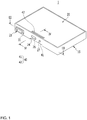
FIG. 1 illustrates a perspective view of a rechargeable battery in accordance with a first embodiment of the present invention. -
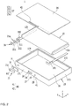
FIG. 2 illustrates an exploded perspective view of the rechargeable battery inFIG. 1 . -
FIG. 3 illustrates a cross-sectional view across a line III-III inFIG. 1 . -
FIG. 4 illustrates a cross-sectional view across a line IV-IV inFIG. 1 . -
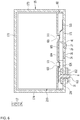
FIG. 5 illustrates an exploded perspective view of a rechargeable battery in accordance with a second embodiment of the present invention. -
FIG. 6 illustrates a cross-sectional view across a line VI-VI inFIG. 5 . -
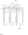
FIG. 7 illustrates a perspective view of a rechargeable battery pack in accordance with an embodiment of the present invention. -
FIG. 1 illustrates a perspective view of a rechargeable battery in accordance with a first embodiment of the present invention, andFIG. 2 illustrates an exploded perspective view of the rechargeable battery inFIG. 1 . Referring toFIGS. 1 and2 , therechargeable battery 1 includes anelectrode assembly 10 for charging and discharging a current, acase 15 for housing theelectrode assembly 10 therein, and anelectrode terminal 21 mounted in a terminal hole H in thecase 15 and electrically connected to theelectrode assembly 10. -
FIG. 3 illustrates a cross-sectional view across a line III-III inFIG. 1 . Referring toFIGS. 2 and3 , theelectrode assembly 10 has a shape of table to be housed in thecase 15, in which a first electrode 11 (also called a "positive electrode") and a second electrode 12 (also called a "negative electrode") arranged at respective sides of aseparator 13 which is an insulator are spirally wound in a jelly-roll shape. - The positive and
negative electrodes portion uncoated portion - The
uncoated portion 11b of thepositive electrode 11 is formed on one end portion of thepositive electrode 11 which is spirally wound. Theuncoated portion 12b of thenegative electrode 12 is formed on one end portion of thenegative electrode 12 which is spirally wound. Further, theuncoated portions electrode assembly 10. - The
case 15 may have a polyhedral shape and preferably a substantially rectangular hexahedral shape having one opened side to form a space for housing theelectrode assembly 10. The opening in thecase 15 is formed in a direction (an z-axis direction) which intersects a plane (xy-plane) of theelectrode assembly 10. The plane contacts the plane having the widest area among the planes forming the case (15). In other words, the opening is formed in a wide side of thecase 15. - Therefore, the
electrode assembly 10 may be placed in thecase 15 in the z-axis direction which intersects the xy-plane. In other words, since theelectrode assembly 10 is placed in the wide opening of thecase 15, the assembling for placing theelectrode assembly 10 in thecase 15 becomes easier. - In one embodiment, the
case 15 has abottom 16 for supporting a flat portion of theelectrode assembly 10 on an opposite side of the rectangular opening, and aside wall 17 having a substantially constant height along an outside circumference of thebottom 16. Thebottom 16 is formed in a substantially rectangular shape that is matched to the flat portion of theelectrode assembly 10, and theside wall 17 is matched to the height of theelectrode assembly 10 in the z-axis direction. - The
side wall 17 includes one pair of a firstlong side wall 171 and a secondlong side wall 172 that are parallel to each other and one pair of a firstshort side wall 173 and a secondshort side wall 174 that are parallel to each other and intersected with and connected to the firstlong side wall 171 and the secondlong side wall 172. The first and secondlong side walls short side walls long side wall 171 has a terminal hole H formed for mounting theelectrode terminal 21 therein. - The
case 15 has avent 26 integral with the case on one side thereof in a direction of extension from the xy-plane of the electrode assembly 10 (an x-axis direction inFIG. 2 ), and a ventprotective portion 40 formed around thevent 16. In one embodiment, thevent 26 is formed in the firstlong side wall 171 to be thinner than the firstlong side wall 171 at the firstlong side wall 171 having the terminal hole H formed therein. - The
case 15 is electrically connected to thepositive electrode 11 and houses theelectrode assembly 10. In one embodiment, thepositive electrode 11 is directly electrically connected to an inside surface of the firstlong side wall 171. Theelectrode assembly 10 is housed in thecase 15 such that the flat portion faces thebottom 16. Accordingly, the spirally wound end portions of thetabular electrode assembly 10 face the first and secondshort side walls - The first
long side wall 171 of thecase 15 has anelectrolyte injection hole 29 adjacent to thevent 26. Theelectrolyte injection hole 29 enables injection of the electrolyte into thecase 15 after coupling and welding the cover 50 to thecase 15. After injecting the electrolyte, theelectrolyte injection hole 29 is closed with asealing plug 27. - Since the
vent 26 is formed by compressing the firstlong side wall 171, arecessed vent hole 24 is formed therein. If the inside pressure of therechargeable battery 1 reaches a preset pressure due to the charging and discharging of the electrode assembly, thevent 26 is opened at thevent hole 24 for discharging the gas, and consequently, the inside pressure is reduced. In one embodiment, thevent 26 may have a notch for inducing the cut open. - The
cover 20 is mounted to the opening of thecase 15 to seal thecase 15. In one embodiment, thecase 15 and thecover 20 of aluminum may be welded together at the opening. - The
positive electrode 11 of theelectrode assembly 10 may be electrically connected to the firstlong side wall 171 of thecase 15 through a first lead tab 181 (hereinafter, "positive electrode lead tab"). In one embodiment, the positiveelectrode lead tab 181 may be directly connected to the inside surface of the firstlong side wall 171 by welding. Accordingly, thecase 15 and thecover 20 in therechargeable battery 1 are charged as the positive electrode and thecase 15 functions as a positive electrode terminal. - The
negative electrode 12 of theelectrode assembly 10 is electrically connected to theelectrode terminal 21 mounted in the terminal hole H in the firstlong side wall 171 through a second lead tab 182 (hereinafter, "negative electrode lead tab"). Theelectrode terminal 21 functions as a negative electrode terminal. - In one embodiment, the
electrode terminal 21 includes aplate terminal 21c arranged on an outside of the firstlong side wall 171 matched to the terminal hole H, and arivet terminal 21a mounted to the firstlong side wall 171 and passed through the terminal hole H to be electrically connected to theelectrode assembly 10 and fastened to theplate terminal 21c. - The
plate terminal 21c has a pass through hole H3, and therivet terminal 21a passes through the terminal hole H with an upper side thereof and is placed in the pass through hole H3. Therivet terminal 21a includes acolumn portion 211 placed in the terminal hole H in the firstlong side wall 171, and aflange portion 212 formed on one end of thecolumn portion 211. Theflange portion 212 has a larger area than a cross-section of thecolumn portion 211 arranged inside of the firstlong side wall 171. -
Gaskets 36 are respectively mounted between thecolumn portion 211 of therivet terminal 21a and an inside surface of the terminal hole H in the firstlong side wall 171 for sealing, and electrically insulating, between thecolumn portion 211 of therivet terminal 21a and the terminal hole H in the firstlong side wall 171. - The
gasket 36 has an extension between theflange portion 212 and the inside surface of the firstlong side wall 171, for further sealing and electrically insulating between theflange portion 212 and the firstlong side wall 171. In other words, at the time theelectrode terminal 21 is mounted to the firstlong side wall 171, thegasket 36 prevents the electrolyte from leaking through the terminal hole H. - The positive and negative
electrode lead tabs long side wall 171 and theelectrode terminal 21 to the positive andnegative electrodes electrode assembly 10, respectively. In other words, the positive and negativeelectrode lead tabs long side wall 171 and therivet terminal 21a on one side, and are connected to theuncoated portions electrode assembly 10 by welding on the other side. - As the
column portion 211 of therivet terminal 21a is placed in acoupling hole 511 in the negativeelectrode lead tab 182, and theflange portion 212 supports surroundings of thecoupling hole 511, therivet terminal 21a is electrically connected to the negativeelectrode lead tab 182. A periphery of thecolumn portion 211 and thecoupling hole 511 may be subjected to caulking or welding. - An insulating
member 31 is placed between theplate terminal 21c on a side of theelectrode terminal 21 and the firstlong side wall 171 for electrically insulating theplate terminal 21c from the firstlong side wall 171. In other words, the firstlong side wall 171 and thecase 15 maintain an insulated state from theelectrode terminal 21. - By coupling the insulating
member 31 and theplate terminal 21c to a top side of therivet terminal 21a and riveting or welding the top side, the insulatingmember 31 and theplate terminal 21c are fastened to the top side of therivet terminal 21a. Theplate terminal 21c is mounted to an outside of the firstlong side wall 171 and the insulatingmember 31 is interposed therebetween. -
FIG. 4 illustrates a cross-sectional view across a line IV-IV inFIG. 1 . Referring toFIG. 4 , the ventprotective portion 40 is constructed of the firstlong side wall 171 adjacent to thevent 26 and thevent hole 24, and a first protrudedportion 41 protruded from the bottom 16 toward an inner side of thecase 15. - By cutting off a path of a swelling pressure which may influence the
vent 26 once as the swelling pressure is transmitted in a direction of the xy-plane of thecase 15, the first protrudedportion 41 provides strong resistance against the swelling pressure acting in the z-axis direction of therechargeable battery 1. In other words, the first protrudedportion 41 increases strength of the firstlong side wall 171 around thevent 26 against the swelling pressure in thecase 15. - Therefore, when swelling pressure acts on the
rechargeable battery 1, the first protrudedportion 41 and the firstlong side wall 171 around the first protrudedportion 41 may maintain shapes thereof, even if thecase 15 and thecover 20 are deformed. In other words, at the time of swelling, the deformation of thevent 26 may be prevented or minimized. Accordingly, even if the swelling occurs at therechargeable battery 1, thevent 26 may open securely under a preset internal pressure. - Further, the vent
protective portion 40 may further include a second protrudedportion 42 protruded to an inner side of thecase 15 from thecover 20 adjacent to thevent 26. By cutting off the path of the swelling pressure which may influence thevent 26 once as the swelling pressure is transmitted in the xy-plane direction of thecase 20, the second protrudedportion 42 provides strong resistance against the swelling pressure acting in the z-axis direction of therechargeable battery 1. In other words, the second protrudedportion 42 increases strength of the firstlong side wall 171 around thevent 26 against the swelling pressure in thecover 20. - Therefore, when the swelling pressure acts on the
rechargeable battery 1, the second protrudedportion 42 and the firstlong side wall 171 around the second protrudedportion 42 may maintain shapes thereof even if thecase 15 and thecover 20 are deformed. In other words, at the time of swelling, deformation of thevent 26 may be prevented. Therefore, even if the swelling occurs at therechargeable battery 1, thevent 26 may open securely at the preset internal pressure. - The
electrolyte injection hole 29 is provided in the firstlong side wall 171 on one side of the first protrudedportion 41 or between the first protrudedportion 41 and the second protrudedportion 42. Therefore, the first protrudedportion 41 or the first and second protrudedportions long side wall 171 which may be weakened by theelectrolyte injection hole 29. - Hereafter, the rechargeable battery in accordance with a second embodiment of the present invention will be described. Configurations that are identical or substantially similar to those of the first preferred embodiment of the present invention will be omitted, and different configurations will be described.
-
FIG. 5 illustrates an exploded perspective view of a rechargeable battery in accordance with a second preferred embodiment of the present invention, andFIG. 6 illustrates a cross-sectional view across a line VI-VI inFIG. 5 . Referring toFIGS. 5 and6 , in the second embodiment of the present invention, therechargeable battery 2 has the spirally wound end portions of anelectrode assembly 210 facing the firstlong side wall 171 and the secondlong side wall 172, respectively. - Even if the spirally wound end portions of the
electrode assembly 210 face the first and secondlong side walls electrode assembly 210 is placed in the z-axis direction which intersects the wide opening of thecase 15, assembling in which theelectrode assembly 210 is placed in thecase 15 becomes easier. - The
rechargeable battery 2 in accordance with the second embodiment of the present invention further includes an insulatingplate 60 mounted between the firstlong side wall 171 and theelectrode assembly 210. The insulatingplate 60 is arranged to an inside surface of the firstlong side wall 171 for insulating the firstlong side wall 171 from theelectrode assembly 210. - The insulating
plate 60 has aninside vent hole 604 matched to thevent hole 24. Since theinside vent hole 604 is formed matched to thevent hole 24 in the firstlong side wall 171, theinside vent hole 604 may transmit the inside pressure raised by the gas generated in theelectrode assembly 210 to thevent hole 24 and discharge it therefrom. - Further, the insulating
plate 60 has an insideelectrolyte injection hole 605 provided matched to theelectrolyte injection hole 29. Since the insideelectrolyte injection hole 605 is formed matched to theelectrolyte injection hole 29 provided to the firstlong side wall 171, the electrolyte injected through theelectrolyte injection hole 29 may be injected into the insulatingplate 60. - The insulating
plate 60 has afirst recess portion 416 matched to the first protrudedportion 41 and asecond recess portion 426 matched to the second protrudedportion 42. Thefirst recess portion 416 receives and supports a side of the first protrudedportion 41 of thecase 15 for preventing interference between thefirst recess portion 416 and the first protrudedportion 41, and thesecond recess portion 426 receives and supports a side of the second protrudedportion 42 of thecover 20 for preventing interference between thesecond recess portion 426 and the second protrudedportion 42. - In one embodiment,
uncoated portions electrode assembly 210 housed in thecase 15 are electrically connected to the firstlong side wall 171 and anelectrode terminal 61 via pass throughholes plate 60, respectively. - The
uncoated portion 111 of the positive electrode is connected to an inside surface of the firstlong side wall 171 with a positiveelectrode lead tab 515 provided between the insulatingplate 60 and the firstlong side wall 171 by welding. Therefore, in therechargeable battery 2, thecase 15 and thecover 20 are charged as positive electrodes and thecase 15 functions as a positive terminal. - The
uncoated portion 121 of thenegative electrode 12 is connected to theelectrode terminal 61 with a negativeelectrode lead tab 525 provided between the insulatingplate 60 and the firstlong side wall 171. Therefore, theelectrode terminal 61 functions as a negative terminal. - The negative
electrode lead tab 525 is welded to arivet terminal 611 of theelectrode terminal 61 between the insulatingplate 60 and the firstlong side wall 171, and therivet terminal 611 is connected to aplate terminal 612 passed through the terminal hole H. In one embodiment, the insulatingmember 31 is located between theplate terminal 612 and the firstlong side wall 171, and agasket 236 is located between therivet terminal 611 and the terminal hole H. - The
rechargeable battery 2 illustrates protection of thevent 26 from the swelling pressure by respectively providing the first and second protrudedportions case 15 and thecover 20, even if the spirally wound end portions of theelectrode assembly 210 face the firstlong side wall 171 and the secondlong side wall 172, respectively. - Hereinafter, a rechargeable battery pack having the rechargeable battery in accordance with an embodiment of the present invention applied thereto will be described. Configurations that are identical or substantially similar to configurations of the rechargeable battery will be omitted, while configurations that are different from the configurations of the rechargeable battery will be described.
-
FIG. 7 illustrates a perspective view of a rechargeable battery pack in accordance with a preferred embodiment of the present invention. Referring toFIG. 7 , therechargeable battery pack 100 in accordance with a first preferred embodiment of the present invention includes a plurality of unit cells (i.e., afirst unit cell 101, asecond unit cell 102, and a third unit cell 103), andbus bars 3 electrically connecting the first, second, andthird unit cells - The
rechargeable battery pack 100 will be described taking therechargeable battery 1 in accordance with the first embodiment of the present invention as an example. Theelectrode terminal 21 of thefirst unit cell 101 and thecase 15 of thesecond unit cell 102 have a height difference ΔH therebetween. Accordingly, thebus bar 3 connects theelectrode terminal 21 of thefirst unit cell 101 to thecase 15 of thesecond unit cell 102 with the height difference ΔH. - As an example, the
bus bar 3 is connected to the firstlong side wall 171 of thecase 15 while being bent to have the height difference ΔH. In this instance, thebus bar 3 is connected to the firstlong side wall 171 of thecase 15 of thesecond unit cell 102. - In other words, by connecting the
bus bars 3 having the height difference ΔH to theelectrode terminals 21 and thecases 15 of the first andsecond unit cells - In the first and
second unit cells rechargeable battery pack 100 that are adjacent to each other, the ventprotective portions 40, i.e., one pair of first protrudedportions 41, are protruded to inner sides of thecases 15 from theside walls 17 and thebottoms 16 of thecases 15, respectively. - Accordingly, the one pair of the first protruded
portions 41 form a first buffering recess G1 between the first andsecond unit cells second unit cell - Further, one pair of the second protruded
portions 42 are protruded to inner sides of thecases 15 from thecovers 20 adjacent to thevents 26, respectively. According to this, the one pair of the second protrudedportions 42 form a second buffering recess G2 between the second andthird unit cells third unit cell - In other words, in the
rechargeable battery pack 100, the first and second buffer recesses G1 and G3 prevent thevents 26 of the other adjacent unit cells from being damaged by swelling of the first, second, orthird unit cell - Although the rechargeable battery and the rechargeable battery pack in accordance with embodiments of the present invention have been described, the present invention is not limited to this, and variations and modifications are possible within the scope of the claims, detailed description of the present invention, and accompanying drawings, which belong to the scope of the present invention.
Claims (10)
- A rechargeable battery comprising:an electrode assembly (10);a case (15) for accommodating the electrode assembly (10), said case being in a polyhedral shape and comprising a bottom (16) for supporting a flat portion of the electrode assembly (10), a side wall (17) extending along a circumference of the bottom (16) with a height less than the lengths of each lateral side of the bottom (16) and an opening formed in a side of the case opposite the bottom (16);a cover (20) for sealing the opening of the case (15);a vent (26) integral with the side wall of the case (15), anda vent protective portion (40) adjacent to the vent (26),characterized in thatthe vent protective portion (40) comprises a first protruded portion (41) protruding to an inner side of the case (15) from the bottom (16) and from the side wall (17), and a second protruded portion (42) protruding to the inner side of the case (15) from the cover (20) adjacent to the vent (26).
- The rechargeable battery of claim 1, wherein the side wall (17) includes:one pair of a first long side wall (171) and a second long side wall (172) parallel to each other; andone pair of a first short side wall (173) and a second short side wall (174) intersecting and connected to the first long side wall (171) and the second long side wall (172) parallel to each other, andwherein the vent (26) is in the first long side wall (171).
- The rechargeable battery of claim 2, wherein the vent protective portion (40) includes the first long side wall (171) adjacent to the vent (26) and a first protruded portion (41) protruding to an inner side of the case (15) from the bottom (16).
- The rechargeable battery of claim 2 or 3, wherein the first long side wall (171) further includes an electrolyte injection hole (29) between the first protruding portion (41) of the case (15) and the second protruding portion (42) of the cover (20) adjacent to the vent (26).
- The rechargeable battery of any one of claims 2 to 4, wherein the electrode assembly (10) has spirally wound end portions facing the first short side wall (173) and the second short side wall (174), respectively.
- The rechargeable battery of one of the preceding claims, wherein the case (15) is electrically connected to a first electrode (11) of the electrode assembly (10), and wherein the case (15) has a terminal hole (H) with an electrode terminal (21) mounted thereto in an insulated state and electrically connected to a second electrode (12) of the electrode assembly (10).
- The rechargeable battery of claim 2, wherein the electrode assembly (210) has spirally wound portions facing the first long side wall (171) and the second long side wall (172), respectively.
- The rechargeable battery of claim 7, further comprising an insulating plate (60) mounted between the first long side wall (171) and the electrode assembly (210),
wherein the electrode assembly (210) has an uncoated portion (111) of the first electrode (11) connected to an inside wall of the first long side wall (171) with a first lead tab (515) by welding, and
wherein the electrode assembly (210) has an uncoated portion (121) of the second electrode (12) connected to the electrode terminal with a second lead tab (525). - A rechargeable battery pack comprising:a plurality of rechargeable batteries according to any one of claims 1 to 8 as unit cells (1); andbus bars (3) for electrically connecting adjacent unit cells (1).wherein the first protruded portion (41) is protruding to an inner side of the case (15) from a side wall (17) and a bottom (16) of the case (15) adjacent to the vent (26) to form a first buffering recess (G1) between adjacent unit cells.
- The rechargeable battery pack of claim 9, wherein the second protruded portion (42) is configured to form a second buffering recess (G2) between adjacent unit cells.
Applications Claiming Priority (1)
| Application Number | Priority Date | Filing Date | Title |
|---|---|---|---|
| KR1020150006989A KR102332446B1 (en) | 2015-01-14 | 2015-01-14 | Rechargeable battery and pack of the same |
Publications (2)
| Publication Number | Publication Date |
|---|---|
| EP3046158A1 EP3046158A1 (en) | 2016-07-20 |
| EP3046158B1 true EP3046158B1 (en) | 2019-10-09 |
Family
ID=54707697
Family Applications (1)
| Application Number | Title | Priority Date | Filing Date |
|---|---|---|---|
| EP15196979.7A Active EP3046158B1 (en) | 2015-01-14 | 2015-11-30 | Rechargeable battery and pack of the same |
Country Status (4)
| Country | Link |
|---|---|
| US (1) | US9705153B2 (en) |
| EP (1) | EP3046158B1 (en) |
| KR (1) | KR102332446B1 (en) |
| CN (1) | CN105789493B (en) |
Families Citing this family (8)
| Publication number | Priority date | Publication date | Assignee | Title |
|---|---|---|---|---|
| KR102260826B1 (en) * | 2016-09-06 | 2021-06-03 | 삼성에스디아이 주식회사 | Rechargeable battery |
| KR102255532B1 (en) * | 2017-05-12 | 2021-05-25 | 주식회사 엘지에너지솔루션 | Secondary battery and the method of manufacturing the same |
| KR102399621B1 (en) * | 2017-05-12 | 2022-05-18 | 현대자동차주식회사 | Battery system |
| US20210074958A1 (en) * | 2019-09-09 | 2021-03-11 | Apple Inc. | Metal can battery |
| JP2021082477A (en) * | 2019-11-19 | 2021-05-27 | トヨタ自動車株式会社 | Battery pack |
| JP2023547007A (en) * | 2021-09-30 | 2023-11-09 | 寧徳時代新能源科技股▲分▼有限公司 | Battery cells, batteries, power consumption devices, and battery cell manufacturing methods and manufacturing equipment |
| WO2023070677A1 (en) * | 2021-11-01 | 2023-05-04 | 宁德时代新能源科技股份有限公司 | Battery cell, battery, electrical device, and method and device for manufacturing battery cell |
| CN217719785U (en) * | 2022-07-19 | 2022-11-01 | 宁德时代新能源科技股份有限公司 | Battery cell, battery and power consumption device |
Citations (1)
| Publication number | Priority date | Publication date | Assignee | Title |
|---|---|---|---|---|
| US20130216873A1 (en) * | 2010-08-17 | 2013-08-22 | Li-Tec Battery Gmbh | Electrochemical cell having at least one pressure relief means |
Family Cites Families (12)
| Publication number | Priority date | Publication date | Assignee | Title |
|---|---|---|---|---|
| JPH10112295A (en) * | 1996-08-12 | 1998-04-28 | Sony Corp | Battery and set battery |
| JP4716538B2 (en) | 2000-03-09 | 2011-07-06 | 三洋電機株式会社 | Battery safety valve and manufacturing method thereof |
| JP2001283793A (en) | 2000-03-31 | 2001-10-12 | Sanyo Electric Co Ltd | Battery |
| KR20040048295A (en) * | 2002-12-02 | 2004-06-07 | 히다치 막셀 가부시키가이샤 | Battery |
| JP2007179793A (en) | 2005-12-27 | 2007-07-12 | Denso Corp | Cover for sealed battery |
| KR20090099241A (en) * | 2008-03-17 | 2009-09-22 | 삼성에스디아이 주식회사 | Cap assembly and secondary battery using the same |
| JP2009224228A (en) | 2008-03-17 | 2009-10-01 | Toshiba Corp | Battery module and battery pack |
| DE102009035457A1 (en) | 2009-07-31 | 2011-02-03 | Daimler Ag | Battery, in particular vehicle battery |
| KR101201743B1 (en) * | 2011-04-07 | 2012-11-15 | 에스비리모티브 주식회사 | Rechargeable battery |
| KR20130052892A (en) | 2011-11-14 | 2013-05-23 | 에스케이이노베이션 주식회사 | Battery cell, and secondary battery |
| KR101595607B1 (en) * | 2011-12-07 | 2016-02-18 | 주식회사 엘지화학 | Secondary battery with improved safety |
| CN103597631B (en) | 2012-03-28 | 2016-02-03 | 株式会社奥普特尼克斯精密 | Safety valve and electrochemical element |
-
2015
- 2015-01-14 KR KR1020150006989A patent/KR102332446B1/en active IP Right Grant
- 2015-08-25 US US14/835,453 patent/US9705153B2/en active Active
- 2015-10-15 CN CN201510666306.5A patent/CN105789493B/en active Active
- 2015-11-30 EP EP15196979.7A patent/EP3046158B1/en active Active
Patent Citations (1)
| Publication number | Priority date | Publication date | Assignee | Title |
|---|---|---|---|---|
| US20130216873A1 (en) * | 2010-08-17 | 2013-08-22 | Li-Tec Battery Gmbh | Electrochemical cell having at least one pressure relief means |
Also Published As
| Publication number | Publication date |
|---|---|
| CN105789493B (en) | 2020-07-03 |
| CN105789493A (en) | 2016-07-20 |
| EP3046158A1 (en) | 2016-07-20 |
| KR102332446B1 (en) | 2021-11-29 |
| US20160204463A1 (en) | 2016-07-14 |
| US9705153B2 (en) | 2017-07-11 |
| KR20160087973A (en) | 2016-07-25 |
Similar Documents
| Publication | Publication Date | Title |
|---|---|---|
| EP3046158B1 (en) | Rechargeable battery and pack of the same | |
| US20210376430A1 (en) | Rechargeable battery and pack of the same | |
| US10050241B2 (en) | Rechargeable battery | |
| US10056580B2 (en) | Rechargeable battery | |
| US8658296B2 (en) | Rechargeable battery | |
| EP2768069B1 (en) | Battery module | |
| EP3007246B1 (en) | Rechargeable battery | |
| KR102439847B1 (en) | Rechargeable battery | |
| US10910626B2 (en) | Secondary battery including bottom retainer | |
| EP2849263B1 (en) | Rechargeable battery | |
| EP3062362B1 (en) | Recharcheable battery and module thereof | |
| EP3062368B1 (en) | Rechargeable battery | |
| KR101805652B1 (en) | Rechargeable battery pack | |
| JP2015008115A (en) | Secondary battery | |
| US10651455B2 (en) | Rechargeable battery | |
| US9865864B2 (en) | Rechargeable battery | |
| US20140205877A1 (en) | Rechargeable battery | |
| EP3518313B1 (en) | Secondary battery | |
| US20150024241A1 (en) | Rechargeable battery |
Legal Events
| Date | Code | Title | Description |
|---|---|---|---|
| PUAI | Public reference made under article 153(3) epc to a published international application that has entered the european phase |
Free format text: ORIGINAL CODE: 0009012 |
|
| AK | Designated contracting states |
Kind code of ref document: A1 Designated state(s): AL AT BE BG CH CY CZ DE DK EE ES FI FR GB GR HR HU IE IS IT LI LT LU LV MC MK MT NL NO PL PT RO RS SE SI SK SM TR |
|
| AX | Request for extension of the european patent |
Extension state: BA ME |
|
| STAA | Information on the status of an ep patent application or granted ep patent |
Free format text: STATUS: REQUEST FOR EXAMINATION WAS MADE |
|
| 17P | Request for examination filed |
Effective date: 20170120 |
|
| RBV | Designated contracting states (corrected) |
Designated state(s): AL AT BE BG CH CY CZ DE DK EE ES FI FR GB GR HR HU IE IS IT LI LT LU LV MC MK MT NL NO PL PT RO RS SE SI SK SM TR |
|
| STAA | Information on the status of an ep patent application or granted ep patent |
Free format text: STATUS: EXAMINATION IS IN PROGRESS |
|
| 17Q | First examination report despatched |
Effective date: 20180522 |
|
| GRAP | Despatch of communication of intention to grant a patent |
Free format text: ORIGINAL CODE: EPIDOSNIGR1 |
|
| STAA | Information on the status of an ep patent application or granted ep patent |
Free format text: STATUS: GRANT OF PATENT IS INTENDED |
|
| INTG | Intention to grant announced |
Effective date: 20190524 |
|
| GRAS | Grant fee paid |
Free format text: ORIGINAL CODE: EPIDOSNIGR3 |
|
| GRAA | (expected) grant |
Free format text: ORIGINAL CODE: 0009210 |
|
| STAA | Information on the status of an ep patent application or granted ep patent |
Free format text: STATUS: THE PATENT HAS BEEN GRANTED |
|
| AK | Designated contracting states |
Kind code of ref document: B1 Designated state(s): AL AT BE BG CH CY CZ DE DK EE ES FI FR GB GR HR HU IE IS IT LI LT LU LV MC MK MT NL NO PL PT RO RS SE SI SK SM TR |
|
| REG | Reference to a national code |
Ref country code: GB Ref legal event code: FG4D |
|
| REG | Reference to a national code |
Ref country code: CH Ref legal event code: EP |
|
| REG | Reference to a national code |
Ref country code: IE Ref legal event code: FG4D |
|
| REG | Reference to a national code |
Ref country code: DE Ref legal event code: R096 Ref document number: 602015039384 Country of ref document: DE |
|
| REG | Reference to a national code |
Ref country code: AT Ref legal event code: REF Ref document number: 1189847 Country of ref document: AT Kind code of ref document: T Effective date: 20191115 |
|
| REG | Reference to a national code |
Ref country code: NL Ref legal event code: MP Effective date: 20191009 |
|
| REG | Reference to a national code |
Ref country code: LT Ref legal event code: MG4D |
|
| REG | Reference to a national code |
Ref country code: AT Ref legal event code: MK05 Ref document number: 1189847 Country of ref document: AT Kind code of ref document: T Effective date: 20191009 |
|
| PG25 | Lapsed in a contracting state [announced via postgrant information from national office to epo] |
Ref country code: ES Free format text: LAPSE BECAUSE OF FAILURE TO SUBMIT A TRANSLATION OF THE DESCRIPTION OR TO PAY THE FEE WITHIN THE PRESCRIBED TIME-LIMIT Effective date: 20191009 Ref country code: LV Free format text: LAPSE BECAUSE OF FAILURE TO SUBMIT A TRANSLATION OF THE DESCRIPTION OR TO PAY THE FEE WITHIN THE PRESCRIBED TIME-LIMIT Effective date: 20191009 Ref country code: SE Free format text: LAPSE BECAUSE OF FAILURE TO SUBMIT A TRANSLATION OF THE DESCRIPTION OR TO PAY THE FEE WITHIN THE PRESCRIBED TIME-LIMIT Effective date: 20191009 Ref country code: AT Free format text: LAPSE BECAUSE OF FAILURE TO SUBMIT A TRANSLATION OF THE DESCRIPTION OR TO PAY THE FEE WITHIN THE PRESCRIBED TIME-LIMIT Effective date: 20191009 Ref country code: PL Free format text: LAPSE BECAUSE OF FAILURE TO SUBMIT A TRANSLATION OF THE DESCRIPTION OR TO PAY THE FEE WITHIN THE PRESCRIBED TIME-LIMIT Effective date: 20191009 Ref country code: LT Free format text: LAPSE BECAUSE OF FAILURE TO SUBMIT A TRANSLATION OF THE DESCRIPTION OR TO PAY THE FEE WITHIN THE PRESCRIBED TIME-LIMIT Effective date: 20191009 Ref country code: NL Free format text: LAPSE BECAUSE OF FAILURE TO SUBMIT A TRANSLATION OF THE DESCRIPTION OR TO PAY THE FEE WITHIN THE PRESCRIBED TIME-LIMIT Effective date: 20191009 Ref country code: PT Free format text: LAPSE BECAUSE OF FAILURE TO SUBMIT A TRANSLATION OF THE DESCRIPTION OR TO PAY THE FEE WITHIN THE PRESCRIBED TIME-LIMIT Effective date: 20200210 Ref country code: NO Free format text: LAPSE BECAUSE OF FAILURE TO SUBMIT A TRANSLATION OF THE DESCRIPTION OR TO PAY THE FEE WITHIN THE PRESCRIBED TIME-LIMIT Effective date: 20200109 Ref country code: GR Free format text: LAPSE BECAUSE OF FAILURE TO SUBMIT A TRANSLATION OF THE DESCRIPTION OR TO PAY THE FEE WITHIN THE PRESCRIBED TIME-LIMIT Effective date: 20200110 Ref country code: FI Free format text: LAPSE BECAUSE OF FAILURE TO SUBMIT A TRANSLATION OF THE DESCRIPTION OR TO PAY THE FEE WITHIN THE PRESCRIBED TIME-LIMIT Effective date: 20191009 Ref country code: BG Free format text: LAPSE BECAUSE OF FAILURE TO SUBMIT A TRANSLATION OF THE DESCRIPTION OR TO PAY THE FEE WITHIN THE PRESCRIBED TIME-LIMIT Effective date: 20200109 |
|
| PG25 | Lapsed in a contracting state [announced via postgrant information from national office to epo] |
Ref country code: HR Free format text: LAPSE BECAUSE OF FAILURE TO SUBMIT A TRANSLATION OF THE DESCRIPTION OR TO PAY THE FEE WITHIN THE PRESCRIBED TIME-LIMIT Effective date: 20191009 Ref country code: RS Free format text: LAPSE BECAUSE OF FAILURE TO SUBMIT A TRANSLATION OF THE DESCRIPTION OR TO PAY THE FEE WITHIN THE PRESCRIBED TIME-LIMIT Effective date: 20191009 Ref country code: IS Free format text: LAPSE BECAUSE OF FAILURE TO SUBMIT A TRANSLATION OF THE DESCRIPTION OR TO PAY THE FEE WITHIN THE PRESCRIBED TIME-LIMIT Effective date: 20200224 |
|
| PG25 | Lapsed in a contracting state [announced via postgrant information from national office to epo] |
Ref country code: AL Free format text: LAPSE BECAUSE OF FAILURE TO SUBMIT A TRANSLATION OF THE DESCRIPTION OR TO PAY THE FEE WITHIN THE PRESCRIBED TIME-LIMIT Effective date: 20191009 |
|
| REG | Reference to a national code |
Ref country code: CH Ref legal event code: PL |
|
| REG | Reference to a national code |
Ref country code: DE Ref legal event code: R097 Ref document number: 602015039384 Country of ref document: DE |
|
| PG2D | Information on lapse in contracting state deleted |
Ref country code: IS |
|
| PG25 | Lapsed in a contracting state [announced via postgrant information from national office to epo] |
Ref country code: RO Free format text: LAPSE BECAUSE OF FAILURE TO SUBMIT A TRANSLATION OF THE DESCRIPTION OR TO PAY THE FEE WITHIN THE PRESCRIBED TIME-LIMIT Effective date: 20191009 Ref country code: CZ Free format text: LAPSE BECAUSE OF FAILURE TO SUBMIT A TRANSLATION OF THE DESCRIPTION OR TO PAY THE FEE WITHIN THE PRESCRIBED TIME-LIMIT Effective date: 20191009 Ref country code: CH Free format text: LAPSE BECAUSE OF NON-PAYMENT OF DUE FEES Effective date: 20191130 Ref country code: LI Free format text: LAPSE BECAUSE OF NON-PAYMENT OF DUE FEES Effective date: 20191130 Ref country code: LU Free format text: LAPSE BECAUSE OF NON-PAYMENT OF DUE FEES Effective date: 20191130 Ref country code: MC Free format text: LAPSE BECAUSE OF FAILURE TO SUBMIT A TRANSLATION OF THE DESCRIPTION OR TO PAY THE FEE WITHIN THE PRESCRIBED TIME-LIMIT Effective date: 20191009 Ref country code: DK Free format text: LAPSE BECAUSE OF FAILURE TO SUBMIT A TRANSLATION OF THE DESCRIPTION OR TO PAY THE FEE WITHIN THE PRESCRIBED TIME-LIMIT Effective date: 20191009 Ref country code: EE Free format text: LAPSE BECAUSE OF FAILURE TO SUBMIT A TRANSLATION OF THE DESCRIPTION OR TO PAY THE FEE WITHIN THE PRESCRIBED TIME-LIMIT Effective date: 20191009 Ref country code: IS Free format text: LAPSE BECAUSE OF FAILURE TO SUBMIT A TRANSLATION OF THE DESCRIPTION OR TO PAY THE FEE WITHIN THE PRESCRIBED TIME-LIMIT Effective date: 20200209 |
|
| PLBE | No opposition filed within time limit |
Free format text: ORIGINAL CODE: 0009261 |
|
| STAA | Information on the status of an ep patent application or granted ep patent |
Free format text: STATUS: NO OPPOSITION FILED WITHIN TIME LIMIT |
|
| REG | Reference to a national code |
Ref country code: BE Ref legal event code: MM Effective date: 20191130 |
|
| PG25 | Lapsed in a contracting state [announced via postgrant information from national office to epo] |
Ref country code: SM Free format text: LAPSE BECAUSE OF FAILURE TO SUBMIT A TRANSLATION OF THE DESCRIPTION OR TO PAY THE FEE WITHIN THE PRESCRIBED TIME-LIMIT Effective date: 20191009 Ref country code: IT Free format text: LAPSE BECAUSE OF FAILURE TO SUBMIT A TRANSLATION OF THE DESCRIPTION OR TO PAY THE FEE WITHIN THE PRESCRIBED TIME-LIMIT Effective date: 20191009 Ref country code: SK Free format text: LAPSE BECAUSE OF FAILURE TO SUBMIT A TRANSLATION OF THE DESCRIPTION OR TO PAY THE FEE WITHIN THE PRESCRIBED TIME-LIMIT Effective date: 20191009 |
|
| 26N | No opposition filed |
Effective date: 20200710 |
|
| PG25 | Lapsed in a contracting state [announced via postgrant information from national office to epo] |
Ref country code: IE Free format text: LAPSE BECAUSE OF NON-PAYMENT OF DUE FEES Effective date: 20191130 |
|
| REG | Reference to a national code |
Ref country code: DE Ref legal event code: R079 Ref document number: 602015039384 Country of ref document: DE Free format text: PREVIOUS MAIN CLASS: H01M0002020000 Ipc: H01M0050100000 |
|
| PG25 | Lapsed in a contracting state [announced via postgrant information from national office to epo] |
Ref country code: SI Free format text: LAPSE BECAUSE OF FAILURE TO SUBMIT A TRANSLATION OF THE DESCRIPTION OR TO PAY THE FEE WITHIN THE PRESCRIBED TIME-LIMIT Effective date: 20191009 Ref country code: BE Free format text: LAPSE BECAUSE OF NON-PAYMENT OF DUE FEES Effective date: 20191130 |
|
| PG25 | Lapsed in a contracting state [announced via postgrant information from national office to epo] |
Ref country code: CY Free format text: LAPSE BECAUSE OF FAILURE TO SUBMIT A TRANSLATION OF THE DESCRIPTION OR TO PAY THE FEE WITHIN THE PRESCRIBED TIME-LIMIT Effective date: 20191009 |
|
| PG25 | Lapsed in a contracting state [announced via postgrant information from national office to epo] |
Ref country code: MT Free format text: LAPSE BECAUSE OF FAILURE TO SUBMIT A TRANSLATION OF THE DESCRIPTION OR TO PAY THE FEE WITHIN THE PRESCRIBED TIME-LIMIT Effective date: 20191009 Ref country code: HU Free format text: LAPSE BECAUSE OF FAILURE TO SUBMIT A TRANSLATION OF THE DESCRIPTION OR TO PAY THE FEE WITHIN THE PRESCRIBED TIME-LIMIT; INVALID AB INITIO Effective date: 20151130 |
|
| PG25 | Lapsed in a contracting state [announced via postgrant information from national office to epo] |
Ref country code: TR Free format text: LAPSE BECAUSE OF FAILURE TO SUBMIT A TRANSLATION OF THE DESCRIPTION OR TO PAY THE FEE WITHIN THE PRESCRIBED TIME-LIMIT Effective date: 20191009 |
|
| PG25 | Lapsed in a contracting state [announced via postgrant information from national office to epo] |
Ref country code: MK Free format text: LAPSE BECAUSE OF FAILURE TO SUBMIT A TRANSLATION OF THE DESCRIPTION OR TO PAY THE FEE WITHIN THE PRESCRIBED TIME-LIMIT Effective date: 20191009 |
|
| P01 | Opt-out of the competence of the unified patent court (upc) registered |
Effective date: 20230528 |
|
| PGFP | Annual fee paid to national office [announced via postgrant information from national office to epo] |
Ref country code: GB Payment date: 20231102 Year of fee payment: 9 |
|
| PGFP | Annual fee paid to national office [announced via postgrant information from national office to epo] |
Ref country code: FR Payment date: 20231108 Year of fee payment: 9 Ref country code: DE Payment date: 20231031 Year of fee payment: 9 |