EP4415112A1 - Battery module - Google Patents
Battery module Download PDFInfo
- Publication number
- EP4415112A1 EP4415112A1 EP22890297.9A EP22890297A EP4415112A1 EP 4415112 A1 EP4415112 A1 EP 4415112A1 EP 22890297 A EP22890297 A EP 22890297A EP 4415112 A1 EP4415112 A1 EP 4415112A1
- Authority
- EP
- European Patent Office
- Prior art keywords
- heat insulator
- battery module
- battery cell
- heat insulation
- heat
- Prior art date
- Legal status (The legal status is an assumption and is not a legal conclusion. Google has not performed a legal analysis and makes no representation as to the accuracy of the status listed.)
- Granted
Links
Images


Classifications
-
- H—ELECTRICITY
- H01—ELECTRIC ELEMENTS
- H01M—PROCESSES OR MEANS, e.g. BATTERIES, FOR THE DIRECT CONVERSION OF CHEMICAL ENERGY INTO ELECTRICAL ENERGY
- H01M50/00—Constructional details or processes of manufacture of the non-active parts of electrochemical cells other than fuel cells, e.g. hybrid cells
- H01M50/20—Mountings; Secondary casings or frames; Racks, modules or packs; Suspension devices; Shock absorbers; Transport or carrying devices; Holders
- H01M50/204—Racks, modules or packs for multiple batteries or multiple cells
- H01M50/207—Racks, modules or packs for multiple batteries or multiple cells characterised by their shape
- H01M50/211—Racks, modules or packs for multiple batteries or multiple cells characterised by their shape adapted for pouch cells
-
- H—ELECTRICITY
- H01—ELECTRIC ELEMENTS
- H01M—PROCESSES OR MEANS, e.g. BATTERIES, FOR THE DIRECT CONVERSION OF CHEMICAL ENERGY INTO ELECTRICAL ENERGY
- H01M10/00—Secondary cells; Manufacture thereof
- H01M10/60—Heating or cooling; Temperature control
- H01M10/65—Means for temperature control structurally associated with the cells
- H01M10/658—Means for temperature control structurally associated with the cells by thermal insulation or shielding
-
- H—ELECTRICITY
- H01—ELECTRIC ELEMENTS
- H01M—PROCESSES OR MEANS, e.g. BATTERIES, FOR THE DIRECT CONVERSION OF CHEMICAL ENERGY INTO ELECTRICAL ENERGY
- H01M10/00—Secondary cells; Manufacture thereof
- H01M10/60—Heating or cooling; Temperature control
- H01M10/61—Types of temperature control
- H01M10/613—Cooling or keeping cold
-
- H—ELECTRICITY
- H01—ELECTRIC ELEMENTS
- H01M—PROCESSES OR MEANS, e.g. BATTERIES, FOR THE DIRECT CONVERSION OF CHEMICAL ENERGY INTO ELECTRICAL ENERGY
- H01M10/00—Secondary cells; Manufacture thereof
- H01M10/60—Heating or cooling; Temperature control
- H01M10/65—Means for temperature control structurally associated with the cells
- H01M10/653—Means for temperature control structurally associated with the cells characterised by electrically insulating or thermally conductive materials
-
- H—ELECTRICITY
- H01—ELECTRIC ELEMENTS
- H01M—PROCESSES OR MEANS, e.g. BATTERIES, FOR THE DIRECT CONVERSION OF CHEMICAL ENERGY INTO ELECTRICAL ENERGY
- H01M10/00—Secondary cells; Manufacture thereof
- H01M10/60—Heating or cooling; Temperature control
- H01M10/65—Means for temperature control structurally associated with the cells
- H01M10/655—Solid structures for heat exchange or heat conduction
- H01M10/6554—Rods or plates
- H01M10/6555—Rods or plates arranged between the cells
-
- H—ELECTRICITY
- H01—ELECTRIC ELEMENTS
- H01M—PROCESSES OR MEANS, e.g. BATTERIES, FOR THE DIRECT CONVERSION OF CHEMICAL ENERGY INTO ELECTRICAL ENERGY
- H01M50/00—Constructional details or processes of manufacture of the non-active parts of electrochemical cells other than fuel cells, e.g. hybrid cells
- H01M50/20—Mountings; Secondary casings or frames; Racks, modules or packs; Suspension devices; Shock absorbers; Transport or carrying devices; Holders
- H01M50/204—Racks, modules or packs for multiple batteries or multiple cells
-
- H—ELECTRICITY
- H01—ELECTRIC ELEMENTS
- H01M—PROCESSES OR MEANS, e.g. BATTERIES, FOR THE DIRECT CONVERSION OF CHEMICAL ENERGY INTO ELECTRICAL ENERGY
- H01M50/00—Constructional details or processes of manufacture of the non-active parts of electrochemical cells other than fuel cells, e.g. hybrid cells
- H01M50/20—Mountings; Secondary casings or frames; Racks, modules or packs; Suspension devices; Shock absorbers; Transport or carrying devices; Holders
- H01M50/233—Mountings; Secondary casings or frames; Racks, modules or packs; Suspension devices; Shock absorbers; Transport or carrying devices; Holders characterised by physical properties of casings or racks, e.g. dimensions
-
- H—ELECTRICITY
- H01—ELECTRIC ELEMENTS
- H01M—PROCESSES OR MEANS, e.g. BATTERIES, FOR THE DIRECT CONVERSION OF CHEMICAL ENERGY INTO ELECTRICAL ENERGY
- H01M50/00—Constructional details or processes of manufacture of the non-active parts of electrochemical cells other than fuel cells, e.g. hybrid cells
- H01M50/20—Mountings; Secondary casings or frames; Racks, modules or packs; Suspension devices; Shock absorbers; Transport or carrying devices; Holders
- H01M50/289—Mountings; Secondary casings or frames; Racks, modules or packs; Suspension devices; Shock absorbers; Transport or carrying devices; Holders characterised by spacing elements or positioning means within frames, racks or packs
- H01M50/293—Mountings; Secondary casings or frames; Racks, modules or packs; Suspension devices; Shock absorbers; Transport or carrying devices; Holders characterised by spacing elements or positioning means within frames, racks or packs characterised by the material
-
- H—ELECTRICITY
- H01—ELECTRIC ELEMENTS
- H01M—PROCESSES OR MEANS, e.g. BATTERIES, FOR THE DIRECT CONVERSION OF CHEMICAL ENERGY INTO ELECTRICAL ENERGY
- H01M50/00—Constructional details or processes of manufacture of the non-active parts of electrochemical cells other than fuel cells, e.g. hybrid cells
- H01M50/30—Arrangements for facilitating escape of gases
- H01M50/383—Flame arresting or ignition-preventing means
-
- H—ELECTRICITY
- H01—ELECTRIC ELEMENTS
- H01M—PROCESSES OR MEANS, e.g. BATTERIES, FOR THE DIRECT CONVERSION OF CHEMICAL ENERGY INTO ELECTRICAL ENERGY
- H01M50/00—Constructional details or processes of manufacture of the non-active parts of electrochemical cells other than fuel cells, e.g. hybrid cells
- H01M50/50—Current conducting connections for cells or batteries
- H01M50/502—Interconnectors for connecting terminals of adjacent batteries; Interconnectors for connecting cells outside a battery casing
- H01M50/507—Interconnectors for connecting terminals of adjacent batteries; Interconnectors for connecting cells outside a battery casing comprising an arrangement of two or more busbars within a container structure, e.g. busbar modules
-
- H—ELECTRICITY
- H01—ELECTRIC ELEMENTS
- H01M—PROCESSES OR MEANS, e.g. BATTERIES, FOR THE DIRECT CONVERSION OF CHEMICAL ENERGY INTO ELECTRICAL ENERGY
- H01M50/00—Constructional details or processes of manufacture of the non-active parts of electrochemical cells other than fuel cells, e.g. hybrid cells
- H01M50/50—Current conducting connections for cells or batteries
- H01M50/572—Means for preventing undesired use or discharge
- H01M50/584—Means for preventing undesired use or discharge for preventing incorrect connections inside or outside the batteries
- H01M50/588—Means for preventing undesired use or discharge for preventing incorrect connections inside or outside the batteries outside the batteries, e.g. incorrect connections of terminals or busbars
-
- H—ELECTRICITY
- H01—ELECTRIC ELEMENTS
- H01M—PROCESSES OR MEANS, e.g. BATTERIES, FOR THE DIRECT CONVERSION OF CHEMICAL ENERGY INTO ELECTRICAL ENERGY
- H01M50/00—Constructional details or processes of manufacture of the non-active parts of electrochemical cells other than fuel cells, e.g. hybrid cells
- H01M50/50—Current conducting connections for cells or batteries
- H01M50/572—Means for preventing undesired use or discharge
- H01M50/584—Means for preventing undesired use or discharge for preventing incorrect connections inside or outside the batteries
- H01M50/59—Means for preventing undesired use or discharge for preventing incorrect connections inside or outside the batteries characterised by the protection means
- H01M50/593—Spacers; Insulating plates
-
- H—ELECTRICITY
- H01—ELECTRIC ELEMENTS
- H01M—PROCESSES OR MEANS, e.g. BATTERIES, FOR THE DIRECT CONVERSION OF CHEMICAL ENERGY INTO ELECTRICAL ENERGY
- H01M2200/00—Safety devices for primary or secondary batteries
- H01M2200/10—Temperature sensitive devices
-
- Y—GENERAL TAGGING OF NEW TECHNOLOGICAL DEVELOPMENTS; GENERAL TAGGING OF CROSS-SECTIONAL TECHNOLOGIES SPANNING OVER SEVERAL SECTIONS OF THE IPC; TECHNICAL SUBJECTS COVERED BY FORMER USPC CROSS-REFERENCE ART COLLECTIONS [XRACs] AND DIGESTS
- Y02—TECHNOLOGIES OR APPLICATIONS FOR MITIGATION OR ADAPTATION AGAINST CLIMATE CHANGE
- Y02E—REDUCTION OF GREENHOUSE GAS [GHG] EMISSIONS, RELATED TO ENERGY GENERATION, TRANSMISSION OR DISTRIBUTION
- Y02E60/00—Enabling technologies; Technologies with a potential or indirect contribution to GHG emissions mitigation
- Y02E60/10—Energy storage using batteries
Definitions
- the present disclosure relates to a battery module, more particularly, to a battery module including a first heat insulator of a heat insulation pad type disposed between individual battery cells and a second heat insulator made of a thermally expandable material and placed between individual electrode leads, to effectively reduce the risk of fire and explosion by blocking heat and high-temperature particles from moving between the individual battery cells and a bus bar plate.
- a method of adding other components to at least battery module configured of at least one battery cell is generally applied.
- a battery module formed of a U-frame structure capable of improving the quality of components and increasing space utilization has been developed for providing a frame for protecting the inside of the single battery module.
- the battery module having the U-frame structure may include a battery-cell-layered body in which a plurality of battery cells are disposed, an U-structured lower frame forming a bottom surface and both lateral surfaces covering an lower surface and both lateral surfaces of the battery-cell-layered body, and an upper frame covering an upper surface of the battery-cell-layered body.
- the battery cell layered body inevitably generates heat when power is supplied. If heat generation is not effectively controlled, the efficiency of the battery cell layered body might suddenly be deteriorated. In some cases, there could be a risk of fire and explosion.
- Such fire and explosion generally occur from, as heat and high-temperature particles are diffused from one of the battery cells and to other battery cells adjacent to the one.
- KR10-2020-0106378A1 discloses a battery module that may prevent heat or particles from moving to adjacent cells 11 by providing a heat insulation pad 60 in a gap formed between adjacent batter cells 11, as shown in FIG. 1 .
- the heat and high-temperature particles generated in the first battery cell 11 may be prevented from moving to the other battery cell 11 disposed on the right of a fourth battery cell 11 by the heat insulation pad 60 disposed between the fourth battery cell 11 and a fifth battery cell 11.
- the heat and high-temperature particles generated in the first battery cell 11 could be diffused through the open space as a whole, so that the conventional battery cell cannot but have a limitation that the fire and explosion prevention effect using the heat insulation pad 60 can only be halved.
- one object of the present disclosure is invented to solve the above-noted disadvantages of the prior art, and to provide a battery module that may include a first heat insulator formed in a heat insulation pad disposed between individual battery cells, and a second heat insulator formed of a heat expansion material disposed between individual electrode leads, so that a risk of fires and explosion may be effectively reduced by blocking heat and high-temperature particles from moving between individual battery cells and a bus bar plate.
- a further object of the present disclosure is to provide a battery module formed to have a volume smaller than a space formed between individual battery cells and a bus bar plate so that a space formed between the individual battery cells and the bus bar plate can serve as an air passage, thereby effectively maintaining cooling performance when operating in a range of normal temperatures.
- a battery module may include a stacked battery cell body having a first battery cell and a second battery cell adjacent to each other; a plurality of electrode leads electrically connected to the first battery cell and the second battery cell, respectively; a first heat insulator disposed between the first battery cell and the second battery cell; and a second heat insulator disposed between the plurality of electrode leads, and the second heat insulator may be made of a material having a higher coefficient of thermal expansion than the first heat insulator.
- the second heat insulator may be made of a thermally expandable material configured to increase in volume when a predetermined critical temperature is reached.
- the thermally expandable material may include an expanding paper.
- the first heat insulator may be made of a silicone-based material.
- the battery module may further include a bus bar plate configured to electrically connect the plurality of electrode leads to each other.
- the second heat insulator may have a plate shape with a first side fixed to the bus bar plate.
- the second heat insulator may be separated from the first heat insulator prior to expansion of the second heat insulator.
- a second side of the second heat insulator may come into contact with the first heat insulator when the expansion of the second heat insulator starts after the predetermined critical temperature is reached.
- the second heat insulator may be separated from each of the plurality of electrode leads before the expansion of the second heat insulator starts.
- lateral surfaces of the second heat insulator may come into contact with the plurality of electrode leads, respectively.
- a space between the plurality of electric leads may be closed.
- the battery module according to the present disclosure may include a first heat insulator formed in a heat insulation pad disposed between individual battery cells, and a second heat insulator formed of a heat expansion material disposed between individual electrode leads. Accordingly, a risk of fires and explosion may be effectively reduced by blocking heat and high-temperature particles from moving between individual battery cells and a bus bar plate.
- the battery module may be formed to have a volume smaller than a space formed between individual battery cells and a bus bar plate. Accordingly, a space formed between the individual battery cells and the bus bar plate can serve as an air passage, thereby effectively maintaining cooling performance when operating in a range of normal temperatures.
- Battery module 100 Battery cell layered body 110: Battery cell 111: Electrode lead 200: Frame 210: Lower frame 211: Bottom frame 212: Side frame 220: Upper frame 300: End plate 310: First end plate 320: Second end plate 400: Heat insulation cover 410: First heat insulation cover 420: Second heat insulation cover 500: Bus bar plate 600: First heat insulator 700: Second heat insulator
- first may be used to describe various components, these components are not limited by these terms. These terms are only used to distinguish one component from another component, and unless otherwise stated, the first component may be the second component, of course.
- the arrangement of an arbitrary component on the "upper portion (or lower portion)" or “upper (or lower)” of a component means that an arbitrary component is placed in contact with the upper (or lower) surface of the component.
- ком ⁇ онент when a component is described as “linked”, “coupled” or “connected” to another component, the components may be directly connected or connected to each other, but other components may be “interposed” between each component. ", or each component may be “linked”, “coupled” or “connected” through other components.
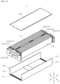
- FIG. 2 is an exploded perspective view of a battery module 1 according to an embodiment of the present disclosure.
- the battery module 1 may include a frame 200 configured of a lower frame 210 and an upper frame 220; a battery cell layered body 100 mounted inside the frame 200, a pair of end plates 300 coupled to an open front and an open rear of the frame 200, a heat insulation cover 400 disposed between the end plate 300 and the frame 200 to heat-insulate between the end plate 300 and the frame 200, and a bus bar plate 500 disposed between the heat insulation cover 400 and the battery cell layered body 100.
- a plurality of battery cells 110 may be layered in close contact, to form the battery cell layered body 100.
- the first heat insulation unit 600 formed as a heat insulation pad may be disposed between adjacent battery cells 110, which will be described later.
- the first heat insulation units 600 may be disposed with one or several battery cells 110 interposed therebetween. In the embodiment shown in FIG. 3 , the first heat insulation units 600 may be disposed with four battery cells 110 interposed therebetween.
- the frame 200 may include a lower frame 210 having a structure surrounding a lower surface and both lateral surfaces of the battery cell layered body 100 in order to accommodate the battery cell layered body 100, and an upper frame 220 disposed on a top surface of the battery cell layered body 100.
- the lower frame 210 may include a bottom frame 220 defining the bottom, and a pair of side frames 210 defining two lateral walls.
- the bottom frame 220 may integrally formed with the pair of side frames 210 as one by a press process of pressing a metal plate having a predetermined strength.
- the upper frame 220 may be configured to cover the upper surface of the battery cell layered body 100, and may be made of a metal plate having a predetermined strength like the lower frame 210.
- the upper frame 220 may be coupled to upper ends of the pair of side frames 210 to be assembled to the lower frame.
- Back ends of both sides of the upper frame 220 and an upper end of the side frame 210 may be coupled to each other by laser welding (L).
- the plurality of battery cells 110 may be pouch- type battery cells, and may be bidirectional battery cells in which positive and negative leads constituting the electrode lead 111 protrude in opposite directions.
- the electrode leads 111 may be electrically connected by using the bus bar plate 500 to connect the plurality of battery cells 110 in series or parallel based on needed output and capacity of a battery module 1.
- the battery cell layered body 100 may further include a cartridge for accommodating the battery cell 110, a buffer member or a cooling means.
- front and rear of the frame 200 may be open.
- the electrode lead 111 of the battery cell layered body 100 may be exposed to the outside through the open front and rear.
- a pair of insulation covers 400, a pair of end plates 300 and a pair of bus bar plates 500 may be disposed on the open front and rear of the frame to face the electrode lead 111.
- the end plates 300 connected with the battery layered body 100 and the bus bar plate plates 500 may be disposed on the frame 200 together with the battery cell layered body 100.
- the battery cell layered body 100 and the bus bar plates 500 may be disposed in the frame 200, and the end plates 300 may be coupled to the frame 200, in a state in which the upper frame 220 is coupled to the frame 200.
- the end plate 300 may be fabricated by a casting method using a metal material, preferably, an iron or alloy material to maintain a predetermined strength.
- the insulation cover 400 may be disposed between the end plate 300 and the bus bar plate 500, and may be configured to insulate heat by physically separate at least the end plate 300 and the bus bar plate 500.
- the insulation cover 400 may include a first insulation cover 420 disposed on the front side and a second insulation cover 420 disposed on the rear side.
- the insulation cover 400 may be fabricated by injection-molding a plastic material capable of maintaining a predetermined strength and low electric conductivity.
- the battery module 1 may further include a first heat insulation unit 600 that is a heat insulation pad or sheet disposed between the battery cells 110.
- the first heat insulation unit 600 may be configured to prevent heat, flame, or high-temperature particles generated in one battery cell 110 from being transferred to adjacent battery cells 110.
- the first heat insulation unit 600 may be formed by processing a silicone material having high insulation performance and electrical insulation into a pad or sheet shape, and may be disposed between the battery cells 111.
- the first heat insulation unit 600 may be formed to have a predetermined elasticity. Through this, when the volume of the battery cell 110 is expanded or cooled to be contracted due to heat or a swelling phenomenon, the first heat insulation unit 600 may be effectively expanded or contracted in response thereto.
- the first heat insulation unit 600 may be disposed to entirely cover one lateral surface of the battery cell 110. However, it is preferred that the first heat insulation unit 600 is disposed not to exceed a front end or a rear end of the battery cell 110. If the first heat insulation unit 600 is disposed to exceed the front end and the rear end of the battery cell 110, it could be difficult to secure the space for connecting the plurality of electrode leads 111 to the bus bar plate 500.
- a single open space may be formed between the front end of the battery cell 110 and between the rear end thereof and the bus bar plate 500.
- Such an open space may serve as a cooling channel through which air flows.
- the first heat insulation unit 600 may be disposed between each two of all the battery cells 111 or intermittently disposed between a predetermined number of battery cells.
- the total of five first heat insulation units 600 may be intermittently provided.
- the present disclosure is not limited thereto. As shown in the drawing, description will be made based on the embodiment in which a total of five first heat insulation units 600 are intermittently disposed.
- the open spaces formed between the front end of the battery cell 110 and the rear end thereof and the bus bar plate 500 may not be blocked or shut off, heat, flame and high-temperature particles might be diffused through the open spaces.
- the battery module 1 may further include a plurality of second heat insulation units 700 disposed between adjacent electrode leads 111.
- the second heat insulation unit 700 formed in a pad or sheet shape may be disposed between the electrode leads, similar to the first heat insulation unit 600.
- the second heat insulation unit 700 may be made of a material having a thermal expansion greater than that of the first heat insulation unit 600.
- the second heat insulation unit 700 may be made of a thermally expandable material whose volume expands when a predetermined critical temperature is reached, for example, an expanding paper.
- the expanding paper is a material characterized of having a volume that increases when a critical temperature of about 100 to 200 is reached.
- the volume of the second heat insulation unit made of the expanding paper may be maintained in an initial state (i.e., an unexpanded state).
- the ambient temperature of the battery cell 110 reaches a critical temperature due to overheating of the battery cell 110, the expanding paper will expand enough to close the open space formed between the battery cell 110 and the bus bar plate 500 as described, referring to FIG. 6 .
- one end of the second heat insulation unit 700 may be fixed to the bus bar plate 500.
- the plurality of second heat insulation units 700 provided in the form of pads may be fixed to a rear surface 511 of a first bus bar plate 510 disposed on the front side or a front surface of a second bus bar plate 520 disposed in the rear side, respectively.
- the space required for assembling between the first bar plate 510, the second bus bar plate 520 and the electrode leads 111 which are coupled to each other may be prevented from being reduced by the second heat insulation unit 700.
- the second heat insulation unit 700 may be arranged parallel to the first heat insulation unit 600, spaced a preset distance apart from the first heat insulation unit 600.
- the second heat insulation unit 700 may be intermittently disposed between the electrode leads 111, similar to the first heat insulation unit 600.
- the second heat insulation unit 700 may be aligned on an extension line of the first heat insulation unit 600 in a front-rear direction (i.e., F-R direction).
- the open space may be effectively closed by direct contact of the second heat insulation unit with the front end and the rear end of the first heat insulation unit 600, which will be described later.
- the second heat insulation unit 700 Before the expansion starts, the second heat insulation unit 700 may be in a state of being separated from the electrode leads 111. When the expansion starts right after the ambient temperature reaches a predetermined critical temperature, both lateral surfaces of the second heat insulation unit 700 may contact the electrode leads 111.
- the open space formed between the electrode leads and between the battery cell 110 and the bus bar plate 500 may be closed by the second heat insulation units 700 of which at least some are expanded.
- the process in which the second heat insulation unit 700 closes the open space formed between the electrode leads 111 and between the battery cell 110 and the bus bar plate 500 will be described based on the second heat insulation unit 700 of which a first end 701 is fixed to the second bus bar plate 520.
- a second end 702 of the second heat insulation unit 700 may keep a state of being separated from the first heat insulation unit 600 with respect to the front-rear direction (i.e., F-R direction).
- the front-rear direction gap G1 between the second end 702 of the second heat insulation unit 700 and the first heat insulation unit 600 may be equal to or smaller than the front-rear direction width S2 of the second heat insulation unit 700. Accordingly, the function of the open space between the battery cells 110 and the second bus bar plate as the cooling channel may be maintained at a proper level.
- the left-right direction width W1 of the second heat insulation unit 700 may be formed smaller than a distance between a pair of adjacent electrode leads 111. Accordingly, interference of the second heat insulation unit 700 with respect to the electrode leads may be minimized.
- the expansion of the second heat insulation unit 700 may start.
- the expansion may proceed simultaneously in the front-rear direction (i.e., F-R direction) and the left-right direction (i.e., Le-Ri direction).
- the second end 702 of the second heat insulation unit 700 may gradually move toward the first heat insulation unit 600.
- the front-rear direction gap G1 between the other end of the second heat insulation unit 700 and the first heat insulation unit 600 may gradually decrease.
- Both lateral surfaces of the second heat insulation unit 700 may move toward the pair of electrode lead 111 facing them, and a gap between the pair of electrode leads may gradually decrease.
- the second end 702 of the second heat insulation unit 700 may be expanded to the first heat insulation unit 600 and both the lateral surfaces of the second heat insulation unit 700 may be expanded to the pair of electrode leads 111.
- the open space formed between the battery cells 110 and the bus bar plate 500 and between the pair of electrode leads 111 may be entirely closed by the second heat insulation unit 700 so that the path P through which heat, flame and high-temperature particles flow may be blocked.
Landscapes
- Chemical & Material Sciences (AREA)
- Chemical Kinetics & Catalysis (AREA)
- Electrochemistry (AREA)
- General Chemical & Material Sciences (AREA)
- Engineering & Computer Science (AREA)
- Manufacturing & Machinery (AREA)
- Connection Of Batteries Or Terminals (AREA)
- Battery Mounting, Suspending (AREA)
- Secondary Cells (AREA)
Abstract
Description
- This application is claims priority to Patent Application No.
10-2021-0150268 filed in the Republic of Korea on November 4, 2021 - The present disclosure relates to a battery module, more particularly, to a battery module including a first heat insulator of a heat insulation pad type disposed between individual battery cells and a second heat insulator made of a thermally expandable material and placed between individual electrode leads, to effectively reduce the risk of fire and explosion by blocking heat and high-temperature particles from moving between the individual battery cells and a bus bar plate.
- With heightened interest in the environment, efforts to reduce carbon emissions are spreading worldwide. To reduce carbon emissions, production of conventional vehicles provided with combustion engines powered by burning fossil fuels is continuously decreasing, while production of electric vehicles powered by electricity is continuously increasing.
- There is increasing demand for secondary batteries, which are mounted in electric vehicles and configured to store electricity. In a situation where the use of personal mobile devices such as smart phones and tablet PCs has become commonplace, there is also continuously increasing demand for such secondary batteries to supply electricity to mobile devices.
- Due to such an increase in demand for secondary batteries, research and development on secondary batteries are being actively conducted.
- At this time, in order to improve the capacity and efficiency of the secondary battery, there is an increasing demand for a battery pack having a multi-module structure in which a plurality of secondary batteries are connected in series and parallel.
- When a battery pack is formed by connecting the plurality of battery cells in series and parallel, a method of adding other components to at least battery module configured of at least one battery cell is generally applied.
- A battery module formed of a U-frame structure capable of improving the quality of components and increasing space utilization has been developed for providing a frame for protecting the inside of the single battery module.
- The battery module having the U-frame structure may include a battery-cell-layered body in which a plurality of battery cells are disposed, an U-structured lower frame forming a bottom surface and both lateral surfaces covering an lower surface and both lateral surfaces of the battery-cell-layered body, and an upper frame covering an upper surface of the battery-cell-layered body.
- Meanwhile, the battery cell layered body inevitably generates heat when power is supplied. If heat generation is not effectively controlled, the efficiency of the battery cell layered body might suddenly be deteriorated. In some cases, there could be a risk of fire and explosion.
- Such fire and explosion generally occur from, as heat and high-temperature particles are diffused from one of the battery cells and to other battery cells adjacent to the one.
- To prevent the fire and explosion,
KR10-2020-0106378A1 adjacent cells 11 by providing aheat insulation pad 60 in a gap formed betweenadjacent batter cells 11, as shown inFIG. 1 . - As shown in the drawing, if a
first battery cell 11 disposed in the leftmost position is overheated, the heat and high-temperature particles generated in thefirst battery cell 11 may be prevented from moving to theother battery cell 11 disposed on the right of afourth battery cell 11 by theheat insulation pad 60 disposed between thefourth battery cell 11 and afifth battery cell 11. - However, according to the configuration of
KR10-2020-0106378A1 bus bar plate 50 and a front end or a rear end of theindividual battery cells 11, which is not blocked from thefirst battery cell 11 to a twenty-fourth battery cell 11. - Accordingly, the heat and high-temperature particles generated in the
first battery cell 11 could be diffused through the open space as a whole, so that the conventional battery cell cannot but have a limitation that the fire and explosion prevention effect using theheat insulation pad 60 can only be halved. - Accordingly, one object of the present disclosure is invented to solve the above-noted disadvantages of the prior art, and to provide a battery module that may include a first heat insulator formed in a heat insulation pad disposed between individual battery cells, and a second heat insulator formed of a heat expansion material disposed between individual electrode leads, so that a risk of fires and explosion may be effectively reduced by blocking heat and high-temperature particles from moving between individual battery cells and a bus bar plate.
- A further object of the present disclosure is to provide a battery module formed to have a volume smaller than a space formed between individual battery cells and a bus bar plate so that a space formed between the individual battery cells and the bus bar plate can serve as an air passage, thereby effectively maintaining cooling performance when operating in a range of normal temperatures.
- Objects of the present invention are not limited to the above-described objects, and other objects and advantages of the present invention will be understood by the following description and will be more definitely understood through the embodiments of the present invention. It is also to be easily understood that the objectives and advantages of the present invention may be realized and attained by means and a combination thereof described in the appended claims.
- A battery module according to an embodiment of the present disclosure may include a stacked battery cell body having a first battery cell and a second battery cell adjacent to each other; a plurality of electrode leads electrically connected to the first battery cell and the second battery cell, respectively; a first heat insulator disposed between the first battery cell and the second battery cell; and a second heat insulator disposed between the plurality of electrode leads, and the second heat insulator may be made of a material having a higher coefficient of thermal expansion than the first heat insulator.
- The second heat insulator may be made of a thermally expandable material configured to increase in volume when a predetermined critical temperature is reached.
- The thermally expandable material may include an expanding paper.
- The first heat insulator may be made of a silicone-based material.
- The battery module may further include a bus bar plate configured to electrically connect the plurality of electrode leads to each other.
- The second heat insulator may have a plate shape with a first side fixed to the bus bar plate.
- The second heat insulator may be separated from the first heat insulator prior to expansion of the second heat insulator.
- A second side of the second heat insulator may come into contact with the first heat insulator when the expansion of the second heat insulator starts after the predetermined critical temperature is reached.
- The second heat insulator may be separated from each of the plurality of electrode leads before the expansion of the second heat insulator starts.
- When the expansion of the second heat insulator starts after the predetermined critical temperature is reached, lateral surfaces of the second heat insulator may come into contact with the plurality of electrode leads, respectively.
- Once the expansion of the second heat insulator is completed, a space between the plurality of electric leads may be closed.
- The battery module according to the present disclosure may include a first heat insulator formed in a heat insulation pad disposed between individual battery cells, and a second heat insulator formed of a heat expansion material disposed between individual electrode leads. Accordingly, a risk of fires and explosion may be effectively reduced by blocking heat and high-temperature particles from moving between individual battery cells and a bus bar plate.
- In addition, the battery module may be formed to have a volume smaller than a space formed between individual battery cells and a bus bar plate. Accordingly, a space formed between the individual battery cells and the bus bar plate can serve as an air passage, thereby effectively maintaining cooling performance when operating in a range of normal temperatures.
- In addition to the above-described effects, specific effects of the present invention will be described together with the following detailed description for implementing the present invention.
-
-
FIG. 1 is a schematically sectional view of a battery cell according to prior art; -
FIG. 2 is an exploded perspective view of a battery module according to an embodiment of the present disclosure; -
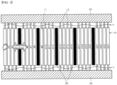
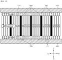
FIG. 3 is a schematic sectional view of the battery module shown inFIG. 2 ; -
FIG. 4 is a rear perspective view showing a state where a second heat insulator is disposed on a first bus bar plate shown inFIG. 2 ; -
FIG. 5 is a partially enlarged view ofFIG. 3 , showing a state where a second heat insulator is not expanded; and -
FIGS. 6 and7 are partially enlarged views ofFIG. 3 , showing a process of expanding a second heat insulator when a critical temperature is reached. - 1: Battery module 100: Battery cell layered body 110: Battery cell 111: Electrode lead 200: Frame 210: Lower frame 211: Bottom frame 212: Side frame 220: Upper frame 300: End plate 310: First end plate 320: Second end plate 400: Heat insulation cover 410: First heat insulation cover 420: Second heat insulation cover 500: Bus bar plate 600: First heat insulator 700: Second heat insulator
- The above-described aspects, features and advantages are specifically described hereunder with reference to the accompanying drawings such that one having ordinary skill in the art to which the present disclosure pertains can easily implement the technical spirit of the disclosure. In the disclosure, detailed descriptions of known technologies in relation to the disclosure are omitted if they are deemed to make the gist of the disclosure unnecessarily vague. Below, preferred embodiments according to the disclosure are specifically described with reference to the accompanying drawings. In the drawings, identical reference numerals can denote identical or similar components.
- Although "first", "second", and the like may be used to describe various components, these components are not limited by these terms. These terms are only used to distinguish one component from another component, and unless otherwise stated, the first component may be the second component, of course.
- Throughout the specification, unless otherwise stated, each component may be singular or plural.
- Hereinafter, the arrangement of an arbitrary component on the "upper portion (or lower portion)" or "upper (or lower)" of a component means that an arbitrary component is placed in contact with the upper (or lower) surface of the component. In addition, it may mean that other components may be interposed between the component and any component disposed on (or under) the component.
- In addition, when a component is described as "linked", "coupled" or "connected" to another component, the components may be directly connected or connected to each other, but other components may be "interposed" between each component. ", or each component may be "linked", "coupled" or "connected" through other components.
- Singular expressions used herein include plural expressions unless the context clearly dictates otherwise. In this application, terms such as "consisting of" or "comprising" should not be construed as necessarily including all of the various components or steps described in the specification. It should be construed that it may not include some of the components or some of the steps. Or may further include additional components or steps.
- Further, singular expressions used herein include plural expressions unless the context clearly dictates otherwise. In this application, terms such as "consisting of" or "comprising" should not be construed as necessarily including all of the various components or steps described in the specification. It should be construed that it may not include some of the components or some of the steps. Or may further include additional components or steps.
- Throughout the specification, when it states "A and/or B", it means A, B or A and B, unless otherwise specified, and when it says "C to D", it means C or more and D or less, unless otherwise specified.
- Hereinafter, referring to the accompanying drawings, a
battery module 1 according to an embodiment of the present disclosure will be described. - Hereinafter, referring to the accompanying drawings, an overall structure of a
battery module 1 according to an embodiment of the present disclosure will be described in detail. -
FIG. 2 is an exploded perspective view of abattery module 1 according to an embodiment of the present disclosure. - Referring to
FIG. 2 , thebattery module 1 according to the embodiment may include aframe 200 configured of alower frame 210 and anupper frame 220; a battery cell layeredbody 100 mounted inside theframe 200, a pair ofend plates 300 coupled to an open front and an open rear of theframe 200, aheat insulation cover 400 disposed between theend plate 300 and theframe 200 to heat-insulate between theend plate 300 and theframe 200, and abus bar plate 500 disposed between theheat insulation cover 400 and the battery cell layeredbody 100. - As shown in the drawing, a plurality of
battery cells 110 may be layered in close contact, to form the battery cell layeredbody 100. - The first
heat insulation unit 600 formed as a heat insulation pad may be disposed betweenadjacent battery cells 110, which will be described later. The firstheat insulation units 600 may be disposed with one orseveral battery cells 110 interposed therebetween. In the embodiment shown inFIG. 3 , the firstheat insulation units 600 may be disposed with fourbattery cells 110 interposed therebetween. - To form a case or housing of the
battery module 1, theframe 200 may include alower frame 210 having a structure surrounding a lower surface and both lateral surfaces of the battery cell layeredbody 100 in order to accommodate the battery cell layeredbody 100, and anupper frame 220 disposed on a top surface of the battery cell layeredbody 100. - As shown in the drawing, the
lower frame 210 may include abottom frame 220 defining the bottom, and a pair of side frames 210 defining two lateral walls. As one example, thebottom frame 220 may integrally formed with the pair of side frames 210 as one by a press process of pressing a metal plate having a predetermined strength. - The
upper frame 220 may be configured to cover the upper surface of the battery cell layeredbody 100, and may be made of a metal plate having a predetermined strength like thelower frame 210. - The
upper frame 220 may be coupled to upper ends of the pair of side frames 210 to be assembled to the lower frame. - Back ends of both sides of the
upper frame 220 and an upper end of theside frame 210 may be coupled to each other by laser welding (L). - The plurality of
battery cells 110 may be pouch- type battery cells, and may be bidirectional battery cells in which positive and negative leads constituting theelectrode lead 111 protrude in opposite directions. - The electrode leads 111 may be electrically connected by using the
bus bar plate 500 to connect the plurality ofbattery cells 110 in series or parallel based on needed output and capacity of abattery module 1. Depending on specification of the applied product, the battery cell layeredbody 100 may further include a cartridge for accommodating thebattery cell 110, a buffer member or a cooling means. - With respect to the drawing, front and rear of the
frame 200 may be open. Theelectrode lead 111 of the battery cell layeredbody 100 may be exposed to the outside through the open front and rear. - A pair of insulation covers 400, a pair of
end plates 300 and a pair ofbus bar plates 500 may be disposed on the open front and rear of the frame to face theelectrode lead 111. - The
end plates 300 connected with the battery layeredbody 100 and the busbar plate plates 500 may be disposed on theframe 200 together with the battery cell layeredbody 100. Or, the battery cell layeredbody 100 and thebus bar plates 500 may be disposed in theframe 200, and theend plates 300 may be coupled to theframe 200, in a state in which theupper frame 220 is coupled to theframe 200. - The
end plate 300 may be fabricated by a casting method using a metal material, preferably, an iron or alloy material to maintain a predetermined strength. - The
insulation cover 400 may be disposed between theend plate 300 and thebus bar plate 500, and may be configured to insulate heat by physically separate at least theend plate 300 and thebus bar plate 500. Theinsulation cover 400 may include afirst insulation cover 420 disposed on the front side and asecond insulation cover 420 disposed on the rear side. - Accordingly, the
insulation cover 400 may be fabricated by injection-molding a plastic material capable of maintaining a predetermined strength and low electric conductivity. - Hereinafter, referring to
FIG. 3 , the specific structure of the firstheat insulation unit 600 and the secondheat insulation unit 700 provided in thebattery module 1 according to an embodiment of the present disclosure will be described in detail. - As shown in
FIG. 2 , thebattery module 1 according to the embodiment of the present disclosure may further include a firstheat insulation unit 600 that is a heat insulation pad or sheet disposed between thebattery cells 110. - The first
heat insulation unit 600 may be configured to prevent heat, flame, or high-temperature particles generated in onebattery cell 110 from being transferred toadjacent battery cells 110. - To prevent movement of heat, flame or high-temperature particles, the first
heat insulation unit 600 may be formed by processing a silicone material having high insulation performance and electrical insulation into a pad or sheet shape, and may be disposed between thebattery cells 111. - In addition, the first
heat insulation unit 600 may be formed to have a predetermined elasticity. Through this, when the volume of thebattery cell 110 is expanded or cooled to be contracted due to heat or a swelling phenomenon, the firstheat insulation unit 600 may be effectively expanded or contracted in response thereto. - The first
heat insulation unit 600 may be disposed to entirely cover one lateral surface of thebattery cell 110. However, it is preferred that the firstheat insulation unit 600 is disposed not to exceed a front end or a rear end of thebattery cell 110. If the firstheat insulation unit 600 is disposed to exceed the front end and the rear end of thebattery cell 110, it could be difficult to secure the space for connecting the plurality of electrode leads 111 to thebus bar plate 500. - Accordingly, a single open space may be formed between the front end of the
battery cell 110 and between the rear end thereof and thebus bar plate 500. Such an open space may serve as a cooling channel through which air flows. - The first
heat insulation unit 600 may be disposed between each two of all thebattery cells 111 or intermittently disposed between a predetermined number of battery cells. - In the embodiment shown in
FIG. 3 , the total of five firstheat insulation units 600 may be intermittently provided. However, the present disclosure is not limited thereto. As shown in the drawing, description will be made based on the embodiment in which a total of five firstheat insulation units 600 are intermittently disposed. - Since the open spaces formed between the front end of the
battery cell 110 and the rear end thereof and thebus bar plate 500 may not be blocked or shut off, heat, flame and high-temperature particles might be diffused through the open spaces. - As means for preventing the heat, flame and high-temperature particles from being diffused through the open space, the
battery module 1 according to an embodiment may further include a plurality of secondheat insulation units 700 disposed between adjacent electrode leads 111. - The second
heat insulation unit 700 formed in a pad or sheet shape may be disposed between the electrode leads, similar to the firstheat insulation unit 600. However, the secondheat insulation unit 700 may be made of a material having a thermal expansion greater than that of the firstheat insulation unit 600. - The second
heat insulation unit 700 may be made of a thermally expandable material whose volume expands when a predetermined critical temperature is reached, for example, an expanding paper. - The expanding paper is a material characterized of having a volume that increases when a critical temperature of about 100 to 200 is reached.
- Accordingly, when the
battery cell 110 is operating in a normal operation temperature range, the volume of the second heat insulation unit made of the expanding paper may be maintained in an initial state (i.e., an unexpanded state). However, when the ambient temperature of thebattery cell 110 reaches a critical temperature due to overheating of thebattery cell 110, the expanding paper will expand enough to close the open space formed between thebattery cell 110 and thebus bar plate 500 as described, referring toFIG. 6 . - When the opening space is closed, a path (P) through which heat, flame and high-temperature particles move to an
adjacent battery cell 110 to the open space may be effectively blocked. - Meanwhile, as shown in
FIGS. 3 and4 , one end of the secondheat insulation unit 700 may be fixed to thebus bar plate 500. - In other words, the plurality of second
heat insulation units 700 provided in the form of pads may be fixed to arear surface 511 of a firstbus bar plate 510 disposed on the front side or a front surface of a secondbus bar plate 520 disposed in the rear side, respectively. - Through this, the space required for assembling between the
first bar plate 510, the secondbus bar plate 520 and the electrode leads 111 which are coupled to each other may be prevented from being reduced by the secondheat insulation unit 700. - To maximize the effect of blocking the heat, flame and high-temperature particles, the second
heat insulation unit 700 may be arranged parallel to the firstheat insulation unit 600, spaced a preset distance apart from the firstheat insulation unit 600. - As shown in the drawing, the second
heat insulation unit 700 may be intermittently disposed between the electrode leads 111, similar to the firstheat insulation unit 600. The secondheat insulation unit 700 may be aligned on an extension line of the firstheat insulation unit 600 in a front-rear direction (i.e., F-R direction). - Accordingly, when the second heat insulation unit is expanded, the open space may be effectively closed by direct contact of the second heat insulation unit with the front end and the rear end of the first
heat insulation unit 600, which will be described later. - Before the expansion starts, the second
heat insulation unit 700 may be in a state of being separated from the electrode leads 111. When the expansion starts right after the ambient temperature reaches a predetermined critical temperature, both lateral surfaces of the secondheat insulation unit 700 may contact the electrode leads 111. - Through this, the open space formed between the electrode leads and between the
battery cell 110 and thebus bar plate 500 may be closed by the secondheat insulation units 700 of which at least some are expanded. - Hereinafter, referring to
FIGS. 5 to 7 , the process in which the secondheat insulation unit 700 closes the open space formed between the electrode leads 111 and between thebattery cell 110 and thebus bar plate 500 will be described based on the secondheat insulation unit 700 of which afirst end 701 is fixed to the secondbus bar plate 520. - As shown in
FIG. 5 , during the operation in a range of normal temperatures, asecond end 702 of the secondheat insulation unit 700 may keep a state of being separated from the firstheat insulation unit 600 with respect to the front-rear direction (i.e., F-R direction). - At this time, the front-rear direction gap G1 between the
second end 702 of the secondheat insulation unit 700 and the firstheat insulation unit 600 may be equal to or smaller than the front-rear direction width S2 of the secondheat insulation unit 700. Accordingly, the function of the open space between thebattery cells 110 and the second bus bar plate as the cooling channel may be maintained at a proper level. - Alternatively, during the operation in a range of normal temperatures, the left-right direction width W1 of the second
heat insulation unit 700 may be formed smaller than a distance between a pair of adjacent electrode leads 111. Accordingly, interference of the secondheat insulation unit 700 with respect to the electrode leads may be minimized. - Meanwhile, as shown in
FIG. 6 , when the ambient temperature of the secondheat insulation unit 700 rises to a predetermined temperature, the expansion of the secondheat insulation unit 700 may start. - At this time, the expansion may proceed simultaneously in the front-rear direction (i.e., F-R direction) and the left-right direction (i.e., Le-Ri direction).
- Accordingly, the
second end 702 of the secondheat insulation unit 700 may gradually move toward the firstheat insulation unit 600. The front-rear direction gap G1 between the other end of the secondheat insulation unit 700 and the firstheat insulation unit 600 may gradually decrease. - Both lateral surfaces of the second
heat insulation unit 700 may move toward the pair ofelectrode lead 111 facing them, and a gap between the pair of electrode leads may gradually decrease. - When such the expansion of the second
heat insulation unit 700 continuously proceeds, thesecond end 702 of the secondheat insulation unit 700 may be expanded to the firstheat insulation unit 600 and both the lateral surfaces of the secondheat insulation unit 700 may be expanded to the pair of electrode leads 111. - Once the expansion of the second
heat insulation unit 700 is completed, the open space formed between thebattery cells 110 and thebus bar plate 500 and between the pair of electrode leads 111 may be entirely closed by the secondheat insulation unit 700 so that the path P through which heat, flame and high-temperature particles flow may be blocked. - Although the present invention has been described with reference to the exemplified drawings, it is to be understood that the present invention is not limited to the embodiments and drawings disclosed in this specification, and those skilled in the art will appreciate that various modifications are possible without departing from the scope and idea of the present invention. Further, although the operating effects according to the configuration of the present invention are not explicitly described while describing an embodiment of the present invention, it should be appreciated that predictable effects are also to be recognized by the configuration.
Claims (10)
- A battery module comprising:a stacked battery cell body having a first battery cell and a second battery cell adjacent to each other;a plurality of electrode leads electrically connected to the first battery cell and the second battery cell, respectively;a first heat insulator disposed between the first battery cell and the second battery cell; anda second heat insulator disposed between the plurality of electrode leads,wherein the second heat insulator is made of a material having a higher coefficient of thermal expansion than that of the first heat insulator.
- The battery module of claim 1, wherein the second heat insulator is made of a thermally expandable material configured to increase in volume when a predetermined critical temperature is reached.
- The battery module of claim 2, wherein the thermally expandable material comprises an expanding paper.
- The battery module of claim 1 or 3, wherein the first heat insulator is made of a silicone-based material.
- The battery module of claim 2, further comprising a bus bar plate configured to electrically connect the plurality of electrode leads to each other,
wherein the second heat insulator has a plate shape with a first side fixed to the bus bar plate. - The battery module of claim 5, wherein the second heat insulator is configured to be separated from the first heat insulator prior to expansion of the second heat insulator.
- The battery module of claim 6, wherein a second side of the second heat insulator is configured to come into contact with the first heat insulator after the expansion of the second heat insulator starts after the predetermined critical temperature is reached.
- The battery module of one of claims 5 to 7, wherein the second heat insulator is configured to be separated from each of the plurality of electrode leads before the expansion of the second heat insulator starts.
- The battery module of claim 8, wherein, when the expansion of the second heat insulator starts after the predetermined critical temperature is reached, lateral surfaces of the second heat insulator are configured to come into contact with the plurality of electrode leads, respectively.
- The battery module of claim 6, wherein, once the expansion of the second heat insulator is completed, a space between the plurality of electric leads is closed.
Applications Claiming Priority (2)
| Application Number | Priority Date | Filing Date | Title |
|---|---|---|---|
| KR1020210150268A KR20230064784A (en) | 2021-11-04 | 2021-11-04 | Battery module |
| PCT/KR2022/016734 WO2023080566A1 (en) | 2021-11-04 | 2022-10-28 | Battery module |
Publications (3)
| Publication Number | Publication Date |
|---|---|
| EP4415112A1 true EP4415112A1 (en) | 2024-08-14 |
| EP4415112A4 EP4415112A4 (en) | 2025-04-30 |
| EP4415112B1 EP4415112B1 (en) | 2026-03-04 |
Family
ID=86241424
Family Applications (1)
| Application Number | Title | Priority Date | Filing Date |
|---|---|---|---|
| EP22890297.9A Active EP4415112B1 (en) | 2021-11-04 | 2022-10-28 | Battery module |
Country Status (6)
| Country | Link |
|---|---|
| US (1) | US20250096366A1 (en) |
| EP (1) | EP4415112B1 (en) |
| JP (1) | JP7823979B2 (en) |
| KR (1) | KR20230064784A (en) |
| CN (1) | CN118202505A (en) |
| WO (1) | WO2023080566A1 (en) |
Families Citing this family (1)
| Publication number | Priority date | Publication date | Assignee | Title |
|---|---|---|---|---|
| KR20250159787A (en) * | 2024-05-03 | 2025-11-11 | 주식회사 엘지에너지솔루션 | Battery assembly and method of manufacturing the same |
Family Cites Families (13)
| Publication number | Priority date | Publication date | Assignee | Title |
|---|---|---|---|---|
| JP4900534B2 (en) * | 2009-02-24 | 2012-03-21 | パナソニック株式会社 | Battery module and battery module assembly using the same |
| JP5993209B2 (en) * | 2012-05-24 | 2016-09-14 | タイガースポリマー株式会社 | Battery cooling structure |
| JP5933344B2 (en) * | 2012-05-31 | 2016-06-08 | 三洋電機株式会社 | Power supply |
| JP2018098074A (en) * | 2016-12-14 | 2018-06-21 | 三菱自動車工業株式会社 | Battery pack |
| JP6912217B2 (en) * | 2017-02-20 | 2021-08-04 | 三菱ケミカル株式会社 | Variable thermal conductivity material |
| DE102018000421A1 (en) * | 2017-12-21 | 2019-06-27 | H.K.O. Isolier- Und Textiltechnik Gmbh | Multilayer thermal insulation element for batteries |
| KR102762534B1 (en) | 2019-03-04 | 2025-02-03 | 주식회사 엘지에너지솔루션 | A battery module comprising a pad composite having swelling absorption and heat shielding function, a battery pack and a vehicle comprising the same |
| KR102380225B1 (en) * | 2019-03-06 | 2022-03-28 | 주식회사 엘지에너지솔루션 | A ESS module having a structure capable of preventing external exposure of a flame and a ESS pack comprising the same |
| KR102814054B1 (en) * | 2019-07-23 | 2025-05-29 | 에스케이온 주식회사 | Bettery module |
| KR102805857B1 (en) * | 2019-10-10 | 2025-05-12 | 주식회사 엘지에너지솔루션 | Battery Module Comprising Heat Insulating Member and Battery Pack Including the Same |
| KR102441418B1 (en) | 2020-06-03 | 2022-09-07 | 현대중공업 주식회사 | Gas supply pump for ship dual fuel engine |
| KR102280326B1 (en) * | 2021-06-08 | 2021-07-22 | 덕양산업 주식회사 | Battery module with thermal runaway delay structure and gas emission structure |
| WO2023080581A1 (en) * | 2021-11-03 | 2023-05-11 | 주식회사 엘지에너지솔루션 | Battery module and battery pack with reinforced safety |
-
2021
- 2021-11-04 KR KR1020210150268A patent/KR20230064784A/en active Pending
-
2022
- 2022-10-28 CN CN202280073129.8A patent/CN118202505A/en active Pending
- 2022-10-28 JP JP2024526709A patent/JP7823979B2/en active Active
- 2022-10-28 EP EP22890297.9A patent/EP4415112B1/en active Active
- 2022-10-28 US US18/707,477 patent/US20250096366A1/en active Pending
- 2022-10-28 WO PCT/KR2022/016734 patent/WO2023080566A1/en not_active Ceased
Also Published As
| Publication number | Publication date |
|---|---|
| KR20230064784A (en) | 2023-05-11 |
| EP4415112B1 (en) | 2026-03-04 |
| WO2023080566A1 (en) | 2023-05-11 |
| JP7823979B2 (en) | 2026-03-04 |
| JP2024540736A (en) | 2024-11-01 |
| US20250096366A1 (en) | 2025-03-20 |
| CN118202505A (en) | 2024-06-14 |
| EP4415112A4 (en) | 2025-04-30 |
Similar Documents
| Publication | Publication Date | Title |
|---|---|---|
| EP3979396B1 (en) | Battery module including heat insulation member and battery pack including the same | |
| KR102397774B1 (en) | Battery module and battery pack having the same | |
| KR102005488B1 (en) | Cell Cover for secondary battery and battery module including the same | |
| JP6804662B2 (en) | Battery module, battery pack including it and automobile | |
| CN111052494A (en) | Battery modules and battery packs | |
| JP2011503800A (en) | Battery assembly having temperature control device | |
| TWI791638B (en) | Battery pack having a bidirectional cooling structure | |
| JP6536497B2 (en) | Battery pack | |
| EP4175044B1 (en) | Battery pack with improved fire protection performance | |
| KR102659210B1 (en) | A battery module that integrates a gas venting channel and a cooling channel, a battery pack including the same, and a method for manufacturing the battery module | |
| KR20220132503A (en) | Battery module with safety device | |
| EP3472891A1 (en) | Cell carrier comprising phase change material | |
| EP4415112A1 (en) | Battery module | |
| JP2015079655A (en) | Battery structure | |
| US20230201640A1 (en) | Battery module with improved fire protection performance | |
| KR20230063249A (en) | Battery module | |
| KR20230015217A (en) | Cooling member and battery pack including the same | |
| JP7789920B2 (en) | Battery module | |
| EP4668449A1 (en) | Battery pack | |
| EP4730490A1 (en) | Battery pack | |
| KR102960996B1 (en) | Battery module with improved fire protection performance | |
| JP7636097B2 (en) | Cooling fin, battery module, battery pack and device including same | |
| JP2026503945A (en) | Devices containing battery packs | |
| KR20260053635A (en) | Battery pack and device including the same | |
| KR20240109837A (en) | Battery pack and device including the same |
Legal Events
| Date | Code | Title | Description |
|---|---|---|---|
| STAA | Information on the status of an ep patent application or granted ep patent |
Free format text: STATUS: THE INTERNATIONAL PUBLICATION HAS BEEN MADE |
|
| PUAI | Public reference made under article 153(3) epc to a published international application that has entered the european phase |
Free format text: ORIGINAL CODE: 0009012 |
|
| STAA | Information on the status of an ep patent application or granted ep patent |
Free format text: STATUS: REQUEST FOR EXAMINATION WAS MADE |
|
| 17P | Request for examination filed |
Effective date: 20240510 |
|
| AK | Designated contracting states |
Kind code of ref document: A1 Designated state(s): AL AT BE BG CH CY CZ DE DK EE ES FI FR GB GR HR HU IE IS IT LI LT LU LV MC ME MK MT NL NO PL PT RO RS SE SI SK SM TR |
|
| DAV | Request for validation of the european patent (deleted) | ||
| DAX | Request for extension of the european patent (deleted) | ||
| A4 | Supplementary search report drawn up and despatched |
Effective date: 20250331 |
|
| RIC1 | Information provided on ipc code assigned before grant |
Ipc: H01M 50/383 20210101ALI20250325BHEP Ipc: H01M 50/233 20210101ALI20250325BHEP Ipc: H01M 50/211 20210101ALI20250325BHEP Ipc: H01M 10/613 20140101ALI20250325BHEP Ipc: H01M 10/658 20140101AFI20250325BHEP |
|
| GRAP | Despatch of communication of intention to grant a patent |
Free format text: ORIGINAL CODE: EPIDOSNIGR1 |
|
| STAA | Information on the status of an ep patent application or granted ep patent |
Free format text: STATUS: GRANT OF PATENT IS INTENDED |
|
| INTG | Intention to grant announced |
Effective date: 20251029 |
|
| P01 | Opt-out of the competence of the unified patent court (upc) registered |
Free format text: CASE NUMBER: UPC_APP_0012217_4415112/2025 Effective date: 20251105 |
|
| GRAS | Grant fee paid |
Free format text: ORIGINAL CODE: EPIDOSNIGR3 |
|
| GRAA | (expected) grant |
Free format text: ORIGINAL CODE: 0009210 |
|
| STAA | Information on the status of an ep patent application or granted ep patent |
Free format text: STATUS: THE PATENT HAS BEEN GRANTED |
|
| AK | Designated contracting states |
Kind code of ref document: B1 Designated state(s): AL AT BE BG CH CY CZ DE DK EE ES FI FR GB GR HR HU IE IS IT LI LT LU LV MC ME MK MT NL NO PL PT RO RS SE SI SK SM TR |
|
| REG | Reference to a national code |
Ref country code: CH Ref legal event code: F10 Free format text: ST27 STATUS EVENT CODE: U-0-0-F10-F00 (AS PROVIDED BY THE NATIONAL OFFICE) Effective date: 20260304 Ref country code: GB Ref legal event code: FG4D |
|
| REG | Reference to a national code |
Ref country code: DE Ref legal event code: R096 Ref document number: 602022031881 Country of ref document: DE |
|
| REG | Reference to a national code |
Ref country code: IE Ref legal event code: FG4D |