EP4415106A1 - All-solid-state battery and method for manufacturing all-solid-state battery - Google Patents
All-solid-state battery and method for manufacturing all-solid-state battery Download PDFInfo
- Publication number
- EP4415106A1 EP4415106A1 EP22878024.3A EP22878024A EP4415106A1 EP 4415106 A1 EP4415106 A1 EP 4415106A1 EP 22878024 A EP22878024 A EP 22878024A EP 4415106 A1 EP4415106 A1 EP 4415106A1
- Authority
- EP
- European Patent Office
- Prior art keywords
- active material
- positive electrode
- electrode active
- material layer
- solid
- Prior art date
- Legal status (The legal status is an assumption and is not a legal conclusion. Google has not performed a legal analysis and makes no representation as to the accuracy of the status listed.)
- Pending
Links
Images



Classifications
-
- H—ELECTRICITY
- H01—ELECTRIC ELEMENTS
- H01M—PROCESSES OR MEANS, e.g. BATTERIES, FOR THE DIRECT CONVERSION OF CHEMICAL ENERGY INTO ELECTRICAL ENERGY
- H01M10/00—Secondary cells; Manufacture thereof
- H01M10/05—Accumulators with non-aqueous electrolyte
- H01M10/056—Accumulators with non-aqueous electrolyte characterised by the materials used as electrolytes, e.g. mixed inorganic/organic electrolytes
- H01M10/0561—Accumulators with non-aqueous electrolyte characterised by the materials used as electrolytes, e.g. mixed inorganic/organic electrolytes the electrolyte being constituted of inorganic materials only
- H01M10/0562—Solid materials
-
- H—ELECTRICITY
- H01—ELECTRIC ELEMENTS
- H01M—PROCESSES OR MEANS, e.g. BATTERIES, FOR THE DIRECT CONVERSION OF CHEMICAL ENERGY INTO ELECTRICAL ENERGY
- H01M50/00—Constructional details or processes of manufacture of the non-active parts of electrochemical cells other than fuel cells, e.g. hybrid cells
- H01M50/40—Separators; Membranes; Diaphragms; Spacing elements inside cells
- H01M50/463—Separators, membranes or diaphragms characterised by their shape
-
- H—ELECTRICITY
- H01—ELECTRIC ELEMENTS
- H01M—PROCESSES OR MEANS, e.g. BATTERIES, FOR THE DIRECT CONVERSION OF CHEMICAL ENERGY INTO ELECTRICAL ENERGY
- H01M10/00—Secondary cells; Manufacture thereof
- H01M10/04—Construction or manufacture in general
- H01M10/0486—Frames for plates or membranes
-
- H—ELECTRICITY
- H01—ELECTRIC ELEMENTS
- H01M—PROCESSES OR MEANS, e.g. BATTERIES, FOR THE DIRECT CONVERSION OF CHEMICAL ENERGY INTO ELECTRICAL ENERGY
- H01M10/00—Secondary cells; Manufacture thereof
- H01M10/05—Accumulators with non-aqueous electrolyte
- H01M10/052—Li-accumulators
-
- H—ELECTRICITY
- H01—ELECTRIC ELEMENTS
- H01M—PROCESSES OR MEANS, e.g. BATTERIES, FOR THE DIRECT CONVERSION OF CHEMICAL ENERGY INTO ELECTRICAL ENERGY
- H01M10/00—Secondary cells; Manufacture thereof
- H01M10/05—Accumulators with non-aqueous electrolyte
- H01M10/058—Construction or manufacture
- H01M10/0585—Construction or manufacture of accumulators having only flat construction elements, i.e. flat positive electrodes, flat negative electrodes and flat separators
-
- H—ELECTRICITY
- H01—ELECTRIC ELEMENTS
- H01M—PROCESSES OR MEANS, e.g. BATTERIES, FOR THE DIRECT CONVERSION OF CHEMICAL ENERGY INTO ELECTRICAL ENERGY
- H01M4/00—Electrodes
- H01M4/02—Electrodes composed of, or comprising, active material
- H01M4/13—Electrodes for accumulators with non-aqueous electrolyte, e.g. for lithium-accumulators; Processes of manufacture thereof
-
- H—ELECTRICITY
- H01—ELECTRIC ELEMENTS
- H01M—PROCESSES OR MEANS, e.g. BATTERIES, FOR THE DIRECT CONVERSION OF CHEMICAL ENERGY INTO ELECTRICAL ENERGY
- H01M4/00—Electrodes
- H01M4/02—Electrodes composed of, or comprising, active material
- H01M4/36—Selection of substances as active materials, active masses, active liquids
- H01M4/362—Composites
- H01M4/366—Composites as layered products
-
- H—ELECTRICITY
- H01—ELECTRIC ELEMENTS
- H01M—PROCESSES OR MEANS, e.g. BATTERIES, FOR THE DIRECT CONVERSION OF CHEMICAL ENERGY INTO ELECTRICAL ENERGY
- H01M50/00—Constructional details or processes of manufacture of the non-active parts of electrochemical cells other than fuel cells, e.g. hybrid cells
- H01M50/40—Separators; Membranes; Diaphragms; Spacing elements inside cells
- H01M50/409—Separators, membranes or diaphragms characterised by the material
- H01M50/411—Organic material
- H01M50/414—Synthetic resins, e.g. thermoplastics or thermosetting resins
-
- Y—GENERAL TAGGING OF NEW TECHNOLOGICAL DEVELOPMENTS; GENERAL TAGGING OF CROSS-SECTIONAL TECHNOLOGIES SPANNING OVER SEVERAL SECTIONS OF THE IPC; TECHNICAL SUBJECTS COVERED BY FORMER USPC CROSS-REFERENCE ART COLLECTIONS [XRACs] AND DIGESTS
- Y02—TECHNOLOGIES OR APPLICATIONS FOR MITIGATION OR ADAPTATION AGAINST CLIMATE CHANGE
- Y02E—REDUCTION OF GREENHOUSE GAS [GHG] EMISSIONS, RELATED TO ENERGY GENERATION, TRANSMISSION OR DISTRIBUTION
- Y02E60/00—Enabling technologies; Technologies with a potential or indirect contribution to GHG emissions mitigation
- Y02E60/10—Energy storage using batteries
-
- Y—GENERAL TAGGING OF NEW TECHNOLOGICAL DEVELOPMENTS; GENERAL TAGGING OF CROSS-SECTIONAL TECHNOLOGIES SPANNING OVER SEVERAL SECTIONS OF THE IPC; TECHNICAL SUBJECTS COVERED BY FORMER USPC CROSS-REFERENCE ART COLLECTIONS [XRACs] AND DIGESTS
- Y02—TECHNOLOGIES OR APPLICATIONS FOR MITIGATION OR ADAPTATION AGAINST CLIMATE CHANGE
- Y02P—CLIMATE CHANGE MITIGATION TECHNOLOGIES IN THE PRODUCTION OR PROCESSING OF GOODS
- Y02P70/00—Climate change mitigation technologies in the production process for final industrial or consumer products
- Y02P70/50—Manufacturing or production processes characterised by the final manufactured product
Definitions
- the present invention relates to an all solid-state battery and a method for manufacturing all solid-state battery.
- This all solid-state battery includes, for example, a positive electrode current collector layer, a positive electrode active material layer, a solid electrolyte layer, a negative electrode active material layer, and a negative electrode current collector layer in this order (See, for example, JP 2020-21551 A ).
- an object of the present invention is to provide an all solid-state battery and a method for manufacturing all solid-state battery capable of reducing damage during the manufacturing process.
- An all solid-state battery includes: a positive electrode current collector; a positive electrode active material layer provided on a surface of the positive electrode current collector; a first elastic member covering a periphery of the positive electrode active material layer and having an elastic modulus less than or equal to an elastic modulus of the positive electrode active material layer; a solid electrolyte layer facing the positive electrode current collector with the first elastic member and the positive electrode active material layer in between; a negative electrode current collector facing the positive electrode current collector with the solid electrolyte layer in between; and a negative electrode active material layer provided between the negative electrode current collector and the solid electrolyte layer and disposed inside a periphery of the solid electrolyte layer.
- An all solid-state battery includes: a positive electrode current collector; a positive electrode active material layer provided on a surface of the positive electrode current collector; a first elastic member covering a periphery of the positive electrode active material layer and having an elastic modulus less than or equal to an elastic modulus of the positive electrode active material layer; a solid electrolyte layer facing the positive electrode current collector with the first elastic member and the positive electrode active material layer in between; a negative electrode current collector facing the positive electrode current collector with the solid electrolyte layer in between; and a negative electrode active material layer provided between the negative electrode current collector and the solid electrolyte layer and disposed inside a periphery of the solid electrolyte layer.
- a first elastic member covering a periphery of a positive electrode active material layer is provided, and a solid electrolyte layer facing a positive electrode current collector with the first elastic member and the positive electrode active material layer in between is provided. Consequently, even when the solid electrolyte layer is pressed during manufacturing, a local force is less likely to be applied to the solid electrolyte layer, and the occurrence of cracking or the like of the solid electrolyte layer is reduced. Thus, it is possible to reduce damage during the manufacturing process.
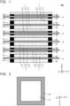
- Fig. 1 shows an example of a configuration of an all solid-state battery 100 according to one embodiment of the present invention.
- the all solid-state battery 100 is, for example, an all-solid lithium secondary battery, and can be charged and discharged a plurality of times.
- the all solid-state battery 100 includes, for example, a plurality of power-generating element portions 1, a plurality of positive electrode current collectors 2, a plurality of negative electrode current collectors 3, a plurality of first elastic members 41, and a plurality of second elastic members 42.
- the positive electrode current collectors 2 and the negative electrode current collectors 3 are alternately laminated, and each of the power-generating element portions 1 is disposed between each of the positive electrode current collectors 2 and each of the negative electrode current collectors 3.
- the positive electrode current collectors 2 are connected in parallel to one another, and the negative electrode current collectors 3 are connected in parallel to one another.
- a direction of lamination of the positive electrode current collectors 2 and the negative electrode current collectors 3 may be referred to as a Z direction, and a direction parallel to principal surfaces of the positive electrode current collectors 2 and the negative electrode current collectors 3 may be referred to as an X direction and a Y direction.
- a laminated structure of the power-generating element portions 1, the positive electrode current collectors 2, and the negative electrode current collectors 3 is sealed with a battery outer casing material (not illustrated) such as a laminate film, and is further sandwiched between two metal plates.
- This laminated structure is pressurized (confined) in the direction of lamination (Z direction).
- the lower limit value of the confining pressure in the direction of lamination applied to the power-generating element portions 1 is, for example, 0.1 MPa or more, preferably 1 MPa or more, more preferably 3 MPa or more, and still more preferably 5 MPa or more.
- the upper limit value of the confining pressure in the direction of lamination applied to the power-generating element portions 1 is, for example, 100 MPa or less, preferably 70 MPa or less, more preferably 40 MPa or less, and still more preferably 10 MPa or less.
- the power-generating element portion 1 includes, for example, a positive electrode active material layer 11, a solid electrolyte layer 12, and a negative electrode active material layer 13. In the all solid-state battery 100, these layers are laminated in the order of the positive electrode active material layer 11, the solid electrolyte layer 12, and the negative electrode active material layer 13 from the positive electrode current collector 2 side.
- the periphery of the power-generating element portion 1 (periphery of the XY plane surface) is provided inside the peripheries of the positive electrode current collector 2 and the negative electrode current collector 3.
- each of the positive electrode active material layer 11, the solid electrolyte layer 12, and the negative electrode active material layer 13 is, for example, a quadrangle such as a rectangle, a circle, an ellipse, or the like.
- the insulating first elastic member 41 is provided together with the positive electrode active material layer 11 between the positive electrode current collector 2 and the solid electrolyte layer 12.
- the insulating second elastic member 42 is provided together with the negative electrode active material layer 13 between the negative electrode current collector 3 and the solid electrolyte layer 12.
- the positive electrode current collector 2 and the negative electrode current collector 3 are conductive members that function as a flow path of electrons during a battery reaction (charge and discharge reaction), and have, for example, a thin plate (foil) shape.
- the negative electrode current collector 3 faces the positive electrode current collector 2 with the power-generating element portion 1 (the solid electrolyte layer 12) in between.
- the materials constituting the positive electrode current collector 2 and the negative electrode current collector 3 are not particularly limited. As the materials constituting the positive electrode current collector 2 and the negative electrode current collector 3, for example, a metal or a resin having conductivity can be adopted.
- the metal examples include aluminum (Al), nickel (Ni), iron (Fe), stainless steel (SUS), titanium (Ti), copper (Cu), and the like.
- a clad material of nickel and aluminum, a clad material of copper and aluminum, or the like may be used.
- the foil may be a foil in which a metal surface is coated with aluminum.
- aluminum, stainless steel, copper, and nickel are preferred from the viewpoint of the electron conductivity, the battery operating potential, and the like.
- the resin having conductivity examples include a resin obtained by adding a conductive filler to a non-conductive polymer material.
- the thicknesses of the positive electrode current collector 2 and the negative electrode current collector 3 are not particularly limited, and are, for example, 10 um to 100 ⁇ m.
- the positive electrode current collector 2 and the negative electrode current collector 3 may have a single-layer structure made of a single material, or may have a laminated structure in which layers made of these materials are appropriately combined. From the viewpoint of weight reduction, it is preferable that the positive electrode current collector 2 and the negative electrode current collector 3 include at least a conductive resin layer made of a resin having conductivity. From the viewpoint of blocking the movement of lithium ions between single battery layers, a metal layer may be provided on a part of the positive electrode current collector 2 and a part of the negative electrode current collector 3.
- the planar (XY plane surface) shape of the positive electrode current collector 2 and the negative electrode current collector 3 is, for example, a quadrangle such as a rectangle, a circle, an ellipse, or the like.
- the size of the XY plane surface of the positive electrode current collector 2 and the size of the XY plane surface of the negative electrode current collector 3 are, for example, approximately identical.
- the positive electrode active material layer 11 is provided on the surface of the positive electrode current collector 2, more specifically, on the principal surface of the positive electrode current collector 2.
- the positive electrode active material layer 11 is provided, for example, on one principal surface and the other principal surface of the positive electrode current collector 2, and the positive electrode current collector 2 is disposed between a pair of the positive electrode active material layers 11.
- the positive electrode active material layer 11 is formed using, for example, NMC 811 (lithium nickel manganese cobalt oxide) as a main raw material. Further, it is preferable that the positive electrode active material layer 11 contains a sulfur-containing positive electrode active material.
- the kind of the sulfur-containing positive electrode active material is not particularly limited, but examples thereof include particles or thin films of an organic sulfur compound or an inorganic sulfur compound in addition to the sulfur simple substance (S), and any material may be used as long as the material can release lithium ions during charging and occlude lithium ions during discharging by utilizing the oxidation-reduction reaction of sulfur.
- the thickness (size in the Z direction) of the positive electrode active material layer 11 varies depending on the configuration of the intended lithium secondary battery, but is, for example, preferably within a range of 0.1 um to 1000 ⁇ m, and more preferably within a range of 40 um to 100 um.
- the thickness of the positive electrode active material layer 11 is preferably larger than the thickness of the negative electrode active material layer 13 at a SOC of 100%.
- the elastic modulus of the positive electrode active material layer 11, specifically, the compressive elastic modulus of the positive electrode active material layer 11 is, for example, 0.1 GPa to 100 GPa, and desirably 3 GPa to 20 GPa.
- the compressive elastic modulus can be determined, for example, as follows. First, a test piece having a diameter of 2 mm is used and the thickness deformation amount is measured by a uniaxial compression test using a universal testing machine. Thereafter, the compressive strain is calculated based on the thickness deformation amount and the initial thickness. Next, a stress-strain diagram is created using the compressive stress measured simultaneously with the thickness deformation amount. The compressive elastic modulus can be obtained from the slope of the stress-strain diagram.
- the solid electrolyte layer 12 is provided to be widened from the positive electrode active material layer 11 and the negative electrode active material layer 13.
- the size of the XY plane surface of the solid electrolyte layer 12 is larger than the size of the XY plane surfaces of the positive electrode active material layer 11 and the negative electrode active material layer 13.
- the solid electrolyte layer 12 is widened from the positive electrode active material layer 11 and the negative electrode active material layer 13, which makes it possible to reduce the occurrence of a short-circuit at the ends of the positive electrode active material layer 11 and the negative electrode active material layer 13.
- the solid electrolyte layer 12 is preferably widened from the positive electrode active material layer 11 and the negative electrode active material layer 13 over the entire periphery.
- the positive electrode active material layer 11 and the first elastic member 41 are provided between the solid electrolyte layer 12 and the positive electrode current collector 2.
- the solid electrolyte layer 12 faces the positive electrode current collector 2 with the first elastic member 41 and the positive electrode active material layer 11 in between.
- the negative electrode active material layer 13 and the second elastic member 42 are provided between the solid electrolyte layer 12 and the negative electrode current collector 3.
- the solid electrolyte layer 12 faces the negative electrode current collector 3 with the second elastic member 42 and the negative electrode active material layer 13 in between.
- the solid electrolyte layer 12 interposed between the positive electrode active material layer 11 and the negative electrode active material layer 13 contains a solid electrolyte as a main component.
- the solid electrolyte include a sulfide solid electrolyte and an oxide solid electrolyte, and a sulfide solid electrolyte is preferred.
- the sulfide solid electrolyte include LPS-based (e.g. argyrodite (Li 6 PS 5 Cl)) materials and LGPS-based (e.g. Li 10 GeP 2 S 12 ) materials.
- the thickness of the solid electrolyte layer 12 varies depending on the configuration of the intended lithium secondary battery, but is, for example, preferably within a range of 0.1 um to 1000 ⁇ m, and more preferably within a range of 10 um to 40 ⁇ m.
- the negative electrode active material layer 13 is provided on the surface of the negative electrode current collector 3, more specifically, on the principal surface of the negative electrode current collector 3.
- the negative electrode active material layer 13 is provided, for example, on one principal surface and the other principal surface of the negative electrode current collector 3, and the negative electrode current collector 3 is disposed between a pair of the negative electrode active material layers 13.
- the negative electrode active material layer 13 provided between the negative electrode current collector 3 and the solid electrolyte layer 12 is disposed inside a periphery (periphery of the XY plane surface) of the solid electrolyte layer 12.
- the negative electrode active material layer 13 is made of a material having electrical conductivity and/or lithium ion conductivity.
- the negative electrode active material layer 13 is made of, for example, a negative electrode active material containing a lithium alloy or a lithium metal.
- the negative electrode active material layer 13 is preferably made of lithium metal.
- the negative electrode active material layer 13 may be made of stainless steel (SUS), copper (Cu), carbon black (carbon fine particles), or the like.
- the thickness of the negative electrode active material layer 13 is, for example, within a range of 0.1 um to 1000 um.
- the compressive elastic modulus of the negative electrode active material layer 13 is, for example, 0.1 GPa to 100 GPa, and desirably 3 GPa to 20 GPa.
- a lithium metal layer (a metal layer 14 in Fig. 15B described later) is deposited between the negative electrode current collector 3 and the solid electrolyte layer 12.
- the negative electrode active material layer 13 at a SOC of 1000 contains an alkali metal such as lithium as a main component, as a result of which the battery capacity of the all solid-state battery 100 can be secured.
- the insulating first elastic member 41 provided between the positive electrode current collector 2 and the solid electrolyte layer 12 covers a periphery of the positive electrode active material layer 11. Hence, the first elastic member 41 is provided in the same layer as the positive electrode active material layer 11. Although details will be described later, the first elastic member 41 is provided, and thus even when the solid electrolyte layer 12 is pressed during manufacturing, a local force is less likely to be applied to the solid electrolyte layer 12, and cracking or the like of the solid electrolyte layer 12 during manufacturing can be reduced.
- Fig. 2 shows an example of planar (XY plane surfaces) shapes of the first elastic member 41 and the positive electrode active material layer 11.
- the first elastic member 41 covers the periphery of the positive electrode active material layer 11 over the entire periphery of the positive electrode active material layer 11.
- the first elastic member 41 is provided, for example, in a frame shape around the positive electrode active material layer 11.
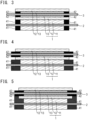
- Fig. 3 shows a part of the all solid-state battery 100 shown in Fig. 1 .
- the thickness (natural length) of the first elastic member 41 provided in the same layer as the positive electrode active material layer 11 is, for example, preferably within a range of 0.1 um to 1000 ⁇ m, and more preferably within a range of 40 um to 100 um.
- the thickness of the first elastic member 41 is preferably approximately the same as the thickness of the positive electrode active material layer 11 at a SOC (State of charge) of 0%, and for example, is preferably 0.9 times or more and 1.0 times or less the thickness of the positive electrode active material layer 11. This makes it possible to more effectively reduce damage of the solid electrolyte layer 12 during manufacturing.
- the thickness of the first elastic member 41 may be larger than the thickness of the positive electrode active material layer 11 as long as the effect is not impaired, and may be, for example, 1.1 times or less the thickness of the positive electrode active material layer 11 at a SOC of 0%.
- the first elastic member 41 is provided, for example, from the position of the periphery of the positive electrode active material layer 11 to the position overlapping the periphery of the solid electrolyte layer 12.
- the periphery of the first elastic member 41 is disposed at the same position as the periphery of the solid electrolyte layer 12 in a planar view (XY plane surface).
- Fig. 4 shows another example of the first elastic member 41.
- the first elastic member 41 may be provided to be widened from the solid electrolyte layer 12, and the periphery of the first elastic member 41 may be disposed outside the periphery of the solid electrolyte layer 12 in a planar view (XY plane surface).
- the first elastic member 41 is provided from the position of the periphery of the positive electrode active material layer 11 to the position overlapping at least the periphery of the solid electrolyte layer 12, whereby damage of the solid electrolyte layer 12 during manufacturing can be more effectively reduced.
- the first elastic member 41 is preferably disposed inside the positive electrode current collector 2 and the negative electrode current collector 3 in a planar view (XY plane surface).
- the first elastic member 41 is provided inside the positive electrode current collector 2 and the negative electrode current collector 3, and thus even when the volume of the all solid-state battery 100 is changed due to charging and discharging, the first elastic member 41 is less likely to be affected by the change. Consequently, a deterioration in the first elastic member 41 can be reduced, and a decrease in reliability of the all solid-state battery 100 can be reduced.
- Figs. 5 and 6 show another example of the first elastic member 41.
- the first elastic member 41 widened from solid electrolyte layer 12 may cover the whole ( Fig. 5 ) or a part ( Fig. 6 ) of the end surface of the solid electrolyte layer 12.
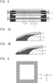
- Figs. 7A and 7B each show the vicinity of an end surface of the solid electrolyte layer 12 in an enlarged manner.
- Fig. 7A shows the end surface of the solid electrolyte layer 12 (e.g. Fig. 4 ) not covered with the first elastic member 41
- Fig. 7B shows the end surface of the solid electrolyte layer 12 (e.g. Fig. 6 ) covered with the first elastic member 41.
- the first elastic member 41 covers the end surface of the solid electrolyte layer 12, whereby the area of contact between the solid electrolyte layer 12 and the first elastic member 41 increases, and the adhesion between them is improved.
- the first elastic member 41 widened from the solid electrolyte layer 12 is preferably disposed from one end (e.g. the lower end) to another end (e.g. the upper end) in the thickness direction (Z direction) of the solid electrolyte layer 12, and is preferably disposed at a position not exceeding the other end of the solid electrolyte layer 12.
- the first elastic member 41 is provided at a position not exceeding the other end in the thickness direction of the solid electrolyte layer 12, whereby a deterioration in battery performance caused by the first elastic member 41 is reduced.
- the first elastic member 41 has an elastic modulus less than or equal to an elastic modulus of the positive electrode active material layer 11.
- the first elastic member 41 is deformed to the same extent as the positive electrode active material layer 11. Accordingly, a predetermined confining pressure is applied to the positive electrode active material layer 11, and the all solid-state battery 100 exhibits desired battery performance.
- the first elastic member 41 is deformed following a volume change of the positive electrode active material layer 11 during charging and discharging of the all solid-state battery 100.
- the elastic modulus of the first elastic member 41 specifically, the compressive elastic modulus is, for example, 0.1 GPa to 100 GPa, and desirably 1 GPa to 10 GPa. Further, the elastic modulus of the first elastic member 41 is preferably equal to the elastic modulus of the positive electrode active material layer 11. This makes it possible to more effectively reduce damage of the solid electrolyte layer 12 during manufacturing.
- the first elastic member 41 is made of, for example, a green compact of an inorganic powder containing polyimide, polyethylene, or a binder.
- the first elastic member 41 may be made of aluminum oxide (Al 2 O 3 , bulk), zirconia (ZrO 2 ), polyethylene terephthalate (PET), Kapton (registered trademark), epoxy resin, polytetrafluoroethylene (PTFE), rubber (natural rubber or synthetic rubber), or the like.
- the insulating second elastic member 42 provided between the negative electrode current collector 3 and the solid electrolyte layer 12 covers the periphery of the negative electrode active material layer 13. Hence, the second elastic member 42 is provided in the same layer as the negative electrode active material layer 13. Providing the second elastic member 42 makes it possible to more effectively reduce cracking or the like of the solid electrolyte layer 12 during manufacturing.
- Fig. 8 shows an example of planar (XY plane surfaces) shapes of the second elastic member 42 and the negative electrode active material layer 13.
- the second elastic member 42 covers the periphery of the negative electrode active material layer 13 over the entire periphery of the negative electrode active material layer 13.
- the second elastic member 42 is provided, for example, in a frame shape around the negative electrode active material layer 13.
- the thickness of the second elastic member 42 provided in the same layer as the negative electrode active material layer 13 is, for example, within a range of 0.1 um to 1000 um.
- the thickness (natural length) of the second elastic member 42 is the same as the thickness of the negative electrode active material layer 13 at a SOC of 0%, or larger than the thickness of the negative electrode active material layer 13. This makes it possible to more effectively reduce damage of the solid electrolyte layer 12 during manufacturing.
- the second elastic member 42 is provided, for example, from the position of the periphery of the negative electrode active material layer 13 to the position overlapping the periphery of the solid electrolyte layer 12, and the periphery of the second elastic member 42 is disposed at the same position as the periphery of the solid electrolyte layer 12 in a planar view (XY plane surface) ( Fig. 3 ).
- the second elastic member 42 may be provided to be widened from the solid electrolyte layer 12, and the periphery of the second elastic member 42 may be disposed outside the periphery of the solid electrolyte layer 12 in a planar view (XY plane surface).
- the position of the periphery of the first elastic member 41 may be different from the position of the periphery of the second elastic member 42.
- the second elastic member 42 is provided from the position of the periphery of the negative electrode active material layer 13 to the position overlapping at least the periphery of the solid electrolyte layer 12, whereby damage of the solid electrolyte layer 12 during manufacturing can be more effectively reduced.
- the second elastic member 42 is preferably disposed inside the positive electrode current collector 2 and the negative electrode current collector 3 in a planar view (XY plane surface).
- the second elastic member 42 is provided inside the positive electrode current collector 2 and the negative electrode current collector 3, and thus even when the volume of the all solid-state battery 100 is changed due to charging and discharging, the second elastic member 42 is less likely to be affected by the change. Consequently, a deterioration in the second elastic member 42 can be reduced, and a decrease in reliability of the all solid-state battery 100 can be reduced.
- Figs. 9 and 10 show another example of the second elastic member 42.
- the second elastic member 42 widened from solid electrolyte layer 12 may cover the whole ( Fig. 9 ) or a part ( Fig. 10 ) of the end surface of solid electrolyte layer 12.
- a part of the end surface of the solid electrolyte layer 12 may be covered with the first elastic member 41, and the rest may be covered with the second elastic member 42 ( Fig. 10 ).
- the second elastic member 42 preferably has an elastic modulus less than or equal to an elastic modulus of the negative electrode active material layer 13, and more preferably has the elastic modulus equal to the elastic modulus of the negative electrode active material layer 13. This makes it possible to more effectively reduce damage of the solid electrolyte layer 12 during manufacturing.
- the second elastic member 42 preferably has an elastic modulus smaller than the elastic modulus of the first elastic member 41.
- the volume of the negative electrode active material layer 13 during charging and discharging is greatly changed as compared with the positive electrode active material layer 11.
- the second elastic member 42 having a smaller elastic modulus is provided at the periphery of the negative electrode active material layer 13, whereby the first elastic member 41 and the second elastic member 42 are easily deformed following the process of charging and discharging of the all solid-state battery 100.
- the second elastic member 42 is deformed following a volume change of the negative electrode active material layer 13 during charging and discharging of the all solid-state battery 100.
- the elastic modulus of the second elastic member 42 is, for example, 0.1 GPa to 100 GPa, and desirably 1 GPa to 10 GPa.
- the second elastic member 42 is made of, for example, polyimide, polyethylene, or ethylene propylene diene rubber (EPDM).
- the second elastic member 42 may be made of aluminum oxide, zirconia, polyethylene terephthalate (PET), Kapton (registered trademark), epoxy resin, polytetrafluoroethylene (PTFE), rubber (natural rubber or synthetic rubber), or the like.
- the second elastic member 42 preferably has rubber elasticity, and preferably contains a rubber material. This makes it possible to more effectively reduce damage of the solid electrolyte layer 12 during manufacturing.
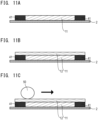
- Figs. 11A to 11C and 12 sequentially show each step of the method for manufacturing the all solid-state battery 100.
- the positive electrode current collector 2 is formed, and then the positive electrode active material layer 11 and the first elastic member 41 are formed on the surface (principal surface) of the positive electrode current collector 2 ( Fig. 11A ).
- the first elastic member 41 is formed using a mask, for example, after forming the positive electrode active material layer 11 on the positive electrode current collector 2.
- the first elastic member 41 is formed by, for example, applying a resin material to the surface of the positive electrode current collector 2.
- the first elastic member 41 may be formed using a transfer method, or the first elastic member 41 may be fixed onto the positive electrode current collector 2 using an adhesive layer.
- the positive electrode active material layer 11 and the first elastic member 41 may be formed on one principal surface and the other principal surface of the positive electrode current collector 2 (see Fig. 13 described later).
- the solid electrolyte layer 12 is formed on the positive electrode active material layer 11 and the first elastic member 41 ( Fig. 11B ).
- the solid electrolyte layer 12 is formed by applying a solid electrolyte onto the positive electrode active material layer 11 and the first elastic member 41 using, for example, a die coater.
- the solid electrolyte layer 12 may be formed using a transfer method.
- the solid electrolyte layer 12 is pressed using a roll press 50 ( Fig. 11C ) to bring the solid electrolyte layer 12 into close contact with the positive electrode active material layer 11.
- the solid electrolyte layer 12 and the positive electrode active material layer 11 are in close contact with each other, as a result of which the contact resistance between the solid electrolyte layer 12 and the positive electrode active material layer 11 is reduced, and the battery performance of the all solid-state battery 100 is improved.
- the first elastic member 41 is formed on the periphery of the positive electrode active material layer 11, a local force is less likely to be applied to the solid electrolyte layer 12 when the solid electrolyte layer 12 is pressed using the roll press 50.
- the solid electrolyte layer 12 may be brought into close contact with the positive electrode active material layer 11 by using isotropic pressure press.
- Fig. 13 shows another example of the step shown in Fig. 11C .
- the solid electrolyte layer 12 formed on one principal surface side and the other principal surface side of the positive electrode current collector 2 may be pressed using the roll press 50 or isotropic pressure press.
- the negative electrode active material layer 13 and the negative electrode current collector 3 are assembled thereto ( Fig. 12 ). Specifically, the negative electrode active material layer 13 and the second elastic member 42 are formed on the surface of the negative electrode current collector 3, and then the negative electrode active material layer 13 is brought into close contact with the solid electrolyte layer 12.
- the positive electrode current collector 2, the positive electrode active material layer 11, the solid electrolyte layer 12, and the negative electrode active material layer 13, and the negative electrode current collector 3 are pressed in the direction of lamination thereof, thereby bringing the negative electrode active material layer 13 into close contact with the solid electrolyte layer 12.
- the second elastic member 42 is formed on the periphery of the negative electrode active material layer 13, a local force is less likely to be applied to the solid electrolyte layer 12 during assembling. Hence, bending stress to the solid electrolyte layer 12 is relaxed, and damage of the solid electrolyte layer 12 during manufacturing can be reduced.
- Fig. 14 shows another example of the step shown in Fig. 12 .
- the negative electrode active material layer 13 and the negative electrode current collector 3 may be assembled to one principal surface side and the other principal surface side of the positive electrode current collector 2.
- Figs. 15A and 15B show examples of the configurations of the all solid-state battery 100 when the SOC is 0% and the all solid-state battery 100 when the SOC is 100 (fully charged state), respectively.
- the all solid-state battery 100 operates, for example, in a state where a predetermined confining pressure is applied in the direction of lamination of the power-generating element portion 1.
- the metal layer 14 is formed between the negative electrode current collector 3 and the solid electrolyte layer 12, more specifically, between the negative electrode current collector 3 and the negative electrode active material layer 13 ( Fig. 15B ).
- the metal layer 14 is formed by lithium (Li) ions in the positive electrode active material layer 11 which have passed through the solid electrolyte layer 12 and precipitated as lithium metal (LiM) on the surface of the negative electrode current collector 3, and functions as the negative electrode active material layer 13.
- the negative electrode active material layer 13 includes the metal layer 14.
- lithium ions pass through the solid electrolyte layer 12 from the negative electrode active material layer 13 and are absorbed in the positive electrode active material layer 11.
- the metal layer 14 disappears ( Fig. 15A ).
- the first elastic member 41 covering the periphery of the positive electrode active material layer 11 is provided, and the solid electrolyte layer 12 facing the positive electrode current collector 2 with the first elastic member 41 and the positive electrode active material layer 11 in between is provided. Consequently, even when the solid electrolyte layer 12 is pressed during manufacturing, a local force is less likely to be applied to the solid electrolyte layer 12, and the occurrence of cracking or the like of the solid electrolyte layer 12 is reduced.
- this action and effect will be described in detail.
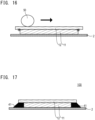
- Fig. 16 shows a step of the method for manufacturing all solid-state battery according to the comparative example, and the step corresponds to the step of Fig. 11C described above.
- the first elastic member e.g. the first elastic member 41 in Fig. 11C
- the solid electrolyte layer 12 is formed to be widened from the positive electrode active material layer 11
- a force is locally applied to the solid electrolyte layer 12 in the vicinity of the periphery of the positive electrode active material layer 11 at the time of pressing by the roll press 50, and bending stress is generated. Due to the bending stress generated in the solid electrolyte layer 12, cracking or the like of the solid electrolyte layer 12 may occur.
- the solid electrolyte layer 12 is formed on the positive electrode active material layer 11 and the first elastic member 41.
- the solid electrolyte layer 12 at the portion widened from the positive electrode active material layer 11 is supported by the first elastic member 41, the bending stress applied to the solid electrolyte layer 12 is relaxed even at the time of pressing by the roll press 50.
- the first elastic member 41 is provided from the position of the periphery of the positive electrode active material layer 11 to the position overlapping at least the periphery of the solid electrolyte layer 12, and thus the entire solid electrolyte layer 12 at the portion widened from the positive electrode active material layer 11 is supported by the first elastic member 41. Therefore, the bending stress applied to solid electrolyte layer 12 is relaxed more effectively.
- the first elastic member 41 has the elastic modulus equal to the elastic modulus of the positive electrode active material layer 11 and has approximately the same thickness as the thickness of the positive electrode active material layer 11, and thus the bending stress applied to the solid electrolyte layer 12 is more effectively relaxed.
- the second elastic member 42 is formed on the periphery of the negative electrode active material layer 13, and thus, when the positive electrode side and the negative electrode side are assembled with the solid electrolyte layer 12 in between, the solid electrolyte layer 12 at the portion widened from the negative electrode active material layer 13 is protected by the second elastic member 42. Therefore, the bending stress applied to the solid electrolyte layer 12 is also relaxed in the assembling step.
- the second elastic member 42 is provided from the position of the periphery of the negative electrode active material layer 13 to the position overlapping at least the periphery of the solid electrolyte layer 12, and thus the entire solid electrolyte layer 12 at the portion widened from the negative electrode active material layer 13 is protected by the second elastic member 42. Therefore, the bending stress applied to solid electrolyte layer 12 is relaxed more effectively.
- the second elastic member 42 has the elastic modulus equal to the elastic modulus of the negative electrode active material layer 13, and thus the bending stress applied to the solid electrolyte layer 12 is relaxed more effectively.
- the first elastic member 41 covering the periphery of the positive electrode active material layer 11 is provided, and the solid electrolyte layer 12 facing the positive electrode current collector 2 with the first elastic member 41 and the positive electrode active material layer 11 in between is provided. Consequently, even when the solid electrolyte layer 12 is pressed during manufacturing, a local force is less likely to be applied to the solid electrolyte layer 12, and the occurrence of cracking or the like of the solid electrolyte layer 12 is reduced. Thus, it is possible to reduce damage during the manufacturing process.
- Fig. 17 shows a configuration of a main part of the all solid-state battery 100 according to a modified example.
- the first elastic member 41 of the all solid-state battery 100 has a tapered shape. Except for this point, the all solid-state battery 100 according to the modified example has the same configuration as the all solid-state battery 100 described in the above embodiment, and exerts a similar action and effect to that of the all solid-state battery 100 described in the above embodiment.
- the first elastic member 41 provided between the solid electrolyte layer 12 and the positive electrode current collector 2 gradually increases from the solid electrolyte layer 12 toward the positive electrode current collector 2.
- the tapered first elastic member 41 has an inclined surface directed outward from the solid electrolyte layer 12 side to the positive electrode current collector 2 side.
- the all solid-state battery 100 is manufactured, for example, as follows. First, the positive electrode current collector 2 is formed, and then the positive electrode active material layer 11 and the tapered first elastic member 41 are formed on the surface of the positive electrode current collector 2 (see Fig. 11A ). Next, the solid electrolyte layer 12 is formed on the positive electrode active material layer 11 and the first elastic member 41 (see Fig. 11B ). Thereafter, for example, the solid electrolyte layer 12 is pressed using the roll press 50 to bring the solid electrolyte layer 12 into close contact with the positive electrode active material layer 11 (see Fig. 11C ). At this time, the roll press 50 is moved along the inclined surface of the first elastic member 41, as a result of which stress is less likely to be applied to the end of the solid electrolyte layer 12.
- the all solid-state battery 100 includes the first elastic member 41 on the periphery of the positive electrode active material layer 11 as described in the above embodiment.
- first elastic member 41 since the first elastic member 41 has a tapered shape, stress is less likely to be applied to the end of the solid electrolyte layer 12. Thus, it is possible reduce damage in the manufacturing process more effectively.
- the all solid-state battery of the present invention has been described above using the embodiment and the modified example.
- the present invention can be appropriately added, modified, and omitted by those skilled in the art within the scope of the technical idea.
- the configuration, shape, size, and the like of each layer of the all solid-state battery described in the above embodiment and modified example are merely examples, and other configurations, shapes, sizes, and the like may be contemplated.
- the laminate type (internal parallel connection type) all-solid lithium secondary battery has been described as an example, but the present invention is also applicable to other secondary batteries such as a bipolar type (bipolar type).
- the all solid-state battery 100 including the plurality of power-generating element portions 1, the plurality of positive electrode current collectors 2, and the plurality of negative electrode current collectors 3 has been described, but the all solid-state battery 100 may have a single-layer structure.
- the positive electrode active material layer 11 and the negative electrode active material layer 13 each having a quadrangular planar shape are illustrated, but the positive electrode active material layer 11 and the negative electrode active material layer 13 may have another planar shape such as a circle or an ellipse.
- the planar shape of the all solid-state battery 100 may be any shape such as a circle, an ellipse, or a quadrangle.
- the metal layer 14 containing a lithium metal is deposited on the negative electrode active material layer 13 when the all solid-state battery 100 is charged.
- the metal layer 14 containing an alkali metal such as sodium (Na) or potassium (K) may be deposited during charging.
- the example in which the negative electrode active material layer 13 is also provided in the all solid-state battery 100 at a SOC of 0% has been described, but the all solid-state battery 100 at a SOC of 0% does not necessarily include the negative electrode active material layer 13.
- the all solid-state battery 100 at a SOC of 0% does not necessarily include the negative electrode active material layer 13.
- only the metal layer 14 deposited during charging may function as the negative electrode active material layer, and the metal layer 14 may correspond to a specific example of the negative electrode active material layer of the present invention.
- the all solid-state battery according to aspect 1 including the features of aspect 2; the all solid-state battery according to aspect 1 or 2, including the features of aspect 3; the all solid-state battery according to any one of aspects 1 to 3, including the features of aspect 4; the all solid-state battery according to any one of aspects 1 to 4, including the features of aspect 5; the all solid-state battery according to any one of aspects 1 to 5, including the features of aspect 6; the all solid-state battery according to aspect 6, including the features of aspect 7; the all solid-state battery according to aspect 6 or 7, including the features of aspect 8; the all solid-state battery according to any one of aspects 6 to 8, including the features of aspect 9; the all solid-state battery according to any one of aspects 1 to 9, including the features of aspect 10; the all solid-state battery according to any one of aspects 1 to 10, including the features of aspect 11; the all solid-state battery according to any one of aspects 1 to 11, including the features of aspect 12; the all solid-state battery according to aspect 12, including the
Landscapes
- Chemical & Material Sciences (AREA)
- Chemical Kinetics & Catalysis (AREA)
- Electrochemistry (AREA)
- General Chemical & Material Sciences (AREA)
- Engineering & Computer Science (AREA)
- Manufacturing & Machinery (AREA)
- Composite Materials (AREA)
- Materials Engineering (AREA)
- Physics & Mathematics (AREA)
- Condensed Matter Physics & Semiconductors (AREA)
- General Physics & Mathematics (AREA)
- Inorganic Chemistry (AREA)
- Secondary Cells (AREA)
- Battery Electrode And Active Subsutance (AREA)
Abstract
Description
- The present invention relates to an all solid-state battery and a method for manufacturing all solid-state battery.
- The development of an all solid-state battery such as an all-solid lithium secondary battery has been actively promoted. This all solid-state battery includes, for example, a positive electrode current collector layer, a positive electrode active material layer, a solid electrolyte layer, a negative electrode active material layer, and a negative electrode current collector layer in this order (See, for example,
JP 2020-21551 A - In such an all solid-state battery, it is desirable to reduce damage during a manufacturing process, such as cracking of each layer. Therefore, an object of the present invention is to provide an all solid-state battery and a method for manufacturing all solid-state battery capable of reducing damage during the manufacturing process.
- An all solid-state battery according to one embodiment of the present invention includes: a positive electrode current collector; a positive electrode active material layer provided on a surface of the positive electrode current collector; a first elastic member covering a periphery of the positive electrode active material layer and having an elastic modulus less than or equal to an elastic modulus of the positive electrode active material layer; a solid electrolyte layer facing the positive electrode current collector with the first elastic member and the positive electrode active material layer in between; a negative electrode current collector facing the positive electrode current collector with the solid electrolyte layer in between; and a negative electrode active material layer provided between the negative electrode current collector and the solid electrolyte layer and disposed inside a periphery of the solid electrolyte layer.
-
-
Fig. 1 is a cross-sectional view showing an example of a configuration of an all solid-state battery according to one embodiment of the present invention. -
Fig. 2 is a view showing planar configurations of a positive electrode active material layer and a first elastic member shown inFig. 1 . -
Fig. 3 is a cross-sectional view showing a part of the all solid-state battery shown inFig. 1 . -
Fig. 4 is a cross-sectional view showing another example of the all solid-state battery shown inFig. 3 . -
Fig. 5 is a cross-sectional view showing another example of the all solid-state battery shown inFig. 3 . -
Fig. 6 is a cross-sectional view showing another example of the all solid-state battery shown inFig. 3 . -
Fig. 7A is an enlarged view showing a part of the solid electrolyte layer and a part of the first elastic member shown inFig. 4 . -
Fig. 7B is an enlarged view showing a part of the solid electrolyte layer and a part of the first elastic member shown inFig. 6 . -
Fig. 8 is a view showing a planar configuration of a negative electrode active material layer and a second elastic member shown inFig. 1 . -
Fig. 9 is a cross-sectional view showing another example of the all solid-state battery shown inFig. 3 . -
Fig. 10 is a cross-sectional view showing another example of the all solid-state battery shown inFig. 3 . -
Fig. 11A is a cross-sectional view showing one step of the method for manufacturing all solid-state battery shown inFig. 1 . -
Fig. 11B is a cross-sectional view showing a step subsequent to the step shown inFig. 11A . -
Fig. 11C is a cross-sectional view showing a step subsequent to the step shown inFig. 11B . -
Fig. 12 is a cross-sectional view showing a step subsequent to the step shown inFig. 11C . -
Fig. 13 is a cross-sectional view showing another example of the step shown inFig. 11C . -
Fig. 14 is a cross-sectional view showing another example of the step shown inFig. 12 . -
Fig. 15A is a cross-sectional view showing a configuration of an all solid-state battery at a SOC (State of charge) of 0%. -
Fig. 15B is a cross-sectional view showing a configuration of an all solid-state battery at a SOC of 100%. -
Fig. 16 is a cross-sectional view showing a method for manufacturing all solid-state battery according to a comparative example. -
Fig. 17 is a cross-sectional view showing a configuration of a main part of an all solid-state battery according to a modified example. - An all solid-state battery according to one embodiment of the present invention includes: a positive electrode current collector; a positive electrode active material layer provided on a surface of the positive electrode current collector; a first elastic member covering a periphery of the positive electrode active material layer and having an elastic modulus less than or equal to an elastic modulus of the positive electrode active material layer; a solid electrolyte layer facing the positive electrode current collector with the first elastic member and the positive electrode active material layer in between; a negative electrode current collector facing the positive electrode current collector with the solid electrolyte layer in between; and a negative electrode active material layer provided between the negative electrode current collector and the solid electrolyte layer and disposed inside a periphery of the solid electrolyte layer. According to the present invention, a first elastic member covering a periphery of a positive electrode active material layer is provided, and a solid electrolyte layer facing a positive electrode current collector with the first elastic member and the positive electrode active material layer in between is provided. Consequently, even when the solid electrolyte layer is pressed during manufacturing, a local force is less likely to be applied to the solid electrolyte layer, and the occurrence of cracking or the like of the solid electrolyte layer is reduced. Thus, it is possible to reduce damage during the manufacturing process.
- Hereinafter, embodiments of the present invention will be described with reference to the drawings, but the technical scope of the present invention is not limited to the following embodiments. Note that dimensional ratios in the drawings are exaggerated for convenience of description, and may be different from actual ratios. Hereinafter, when it is described that the thicknesses of respective parts, the elastic moduli of respective parts, and the like are identical (equal), they may be substantially identical, and include manufacturing errors (e.g. about ± 5%) and the like.
-
Fig. 1 shows an example of a configuration of an all solid-state battery 100 according to one embodiment of the present invention. The all solid-state battery 100 is, for example, an all-solid lithium secondary battery, and can be charged and discharged a plurality of times. The all solid-state battery 100 includes, for example, a plurality of power-generatingelement portions 1, a plurality of positive electrodecurrent collectors 2, a plurality of negative electrodecurrent collectors 3, a plurality of firstelastic members 41, and a plurality of secondelastic members 42. The positiveelectrode current collectors 2 and the negativeelectrode current collectors 3 are alternately laminated, and each of the power-generatingelement portions 1 is disposed between each of the positive electrodecurrent collectors 2 and each of the negativeelectrode current collectors 3. In the all solid-state battery 100, for example, the positive electrodecurrent collectors 2 are connected in parallel to one another, and the negativeelectrode current collectors 3 are connected in parallel to one another. In the following description, a direction of lamination of the positive electrodecurrent collectors 2 and the negative electrodecurrent collectors 3 may be referred to as a Z direction, and a direction parallel to principal surfaces of the positive electrodecurrent collectors 2 and the negative electrodecurrent collectors 3 may be referred to as an X direction and a Y direction. - In the all solid-
state battery 100, for example, a laminated structure of the power-generatingelement portions 1, the positiveelectrode current collectors 2, and the negativeelectrode current collectors 3 is sealed with a battery outer casing material (not illustrated) such as a laminate film, and is further sandwiched between two metal plates. This laminated structure is pressurized (confined) in the direction of lamination (Z direction). The lower limit value of the confining pressure in the direction of lamination applied to the power-generatingelement portions 1 is, for example, 0.1 MPa or more, preferably 1 MPa or more, more preferably 3 MPa or more, and still more preferably 5 MPa or more. The upper limit value of the confining pressure in the direction of lamination applied to the power-generatingelement portions 1 is, for example, 100 MPa or less, preferably 70 MPa or less, more preferably 40 MPa or less, and still more preferably 10 MPa or less. - The power-generating
element portion 1 includes, for example, a positive electrodeactive material layer 11, asolid electrolyte layer 12, and a negative electrodeactive material layer 13. In the all solid-state battery 100, these layers are laminated in the order of the positive electrodeactive material layer 11, thesolid electrolyte layer 12, and the negative electrodeactive material layer 13 from the positiveelectrode current collector 2 side. The periphery of the power-generating element portion 1 (periphery of the XY plane surface) is provided inside the peripheries of the positive electrodecurrent collector 2 and the negative electrodecurrent collector 3. The planar (XY plane surface) shape of each of the positive electrodeactive material layer 11, thesolid electrolyte layer 12, and the negative electrodeactive material layer 13 is, for example, a quadrangle such as a rectangle, a circle, an ellipse, or the like. The insulating firstelastic member 41 is provided together with the positive electrodeactive material layer 11 between the positive electrodecurrent collector 2 and thesolid electrolyte layer 12. The insulating secondelastic member 42 is provided together with the negative electrodeactive material layer 13 between the negative electrodecurrent collector 3 and thesolid electrolyte layer 12. - The positive electrode
current collector 2 and the negative electrodecurrent collector 3 are conductive members that function as a flow path of electrons during a battery reaction (charge and discharge reaction), and have, for example, a thin plate (foil) shape. The negative electrodecurrent collector 3 faces the positive electrodecurrent collector 2 with the power-generating element portion 1 (the solid electrolyte layer 12) in between. The materials constituting the positive electrodecurrent collector 2 and the negative electrodecurrent collector 3 are not particularly limited. As the materials constituting the positive electrodecurrent collector 2 and the negative electrodecurrent collector 3, for example, a metal or a resin having conductivity can be adopted. - Examples of the metal include aluminum (Al), nickel (Ni), iron (Fe), stainless steel (SUS), titanium (Ti), copper (Cu), and the like. In addition to these, a clad material of nickel and aluminum, a clad material of copper and aluminum, or the like may be used. Further, the foil may be a foil in which a metal surface is coated with aluminum. Above all, aluminum, stainless steel, copper, and nickel are preferred from the viewpoint of the electron conductivity, the battery operating potential, and the like. Examples of the resin having conductivity include a resin obtained by adding a conductive filler to a non-conductive polymer material. The thicknesses of the positive electrode
current collector 2 and the negative electrodecurrent collector 3 are not particularly limited, and are, for example, 10 um to 100 µm. - The positive electrode
current collector 2 and the negative electrodecurrent collector 3 may have a single-layer structure made of a single material, or may have a laminated structure in which layers made of these materials are appropriately combined. From the viewpoint of weight reduction, it is preferable that the positive electrodecurrent collector 2 and the negative electrodecurrent collector 3 include at least a conductive resin layer made of a resin having conductivity. From the viewpoint of blocking the movement of lithium ions between single battery layers, a metal layer may be provided on a part of the positive electrodecurrent collector 2 and a part of the negative electrodecurrent collector 3. - The planar (XY plane surface) shape of the positive electrode
current collector 2 and the negative electrodecurrent collector 3 is, for example, a quadrangle such as a rectangle, a circle, an ellipse, or the like. The size of the XY plane surface of the positive electrodecurrent collector 2 and the size of the XY plane surface of the negative electrodecurrent collector 3 are, for example, approximately identical. - The positive electrode
active material layer 11 is provided on the surface of the positive electrodecurrent collector 2, more specifically, on the principal surface of the positive electrodecurrent collector 2. The positive electrodeactive material layer 11 is provided, for example, on one principal surface and the other principal surface of the positive electrodecurrent collector 2, and the positive electrodecurrent collector 2 is disposed between a pair of the positive electrode active material layers 11. - Preferably, the positive electrode
active material layer 11 is formed using, for example, NMC 811 (lithium nickel manganese cobalt oxide) as a main raw material. Further, it is preferable that the positive electrodeactive material layer 11 contains a sulfur-containing positive electrode active material. The kind of the sulfur-containing positive electrode active material is not particularly limited, but examples thereof include particles or thin films of an organic sulfur compound or an inorganic sulfur compound in addition to the sulfur simple substance (S), and any material may be used as long as the material can release lithium ions during charging and occlude lithium ions during discharging by utilizing the oxidation-reduction reaction of sulfur. - The thickness (size in the Z direction) of the positive electrode
active material layer 11 varies depending on the configuration of the intended lithium secondary battery, but is, for example, preferably within a range of 0.1 um to 1000 µm, and more preferably within a range of 40 um to 100 um. The thickness of the positive electrodeactive material layer 11 is preferably larger than the thickness of the negative electrodeactive material layer 13 at a SOC of 100%. - The elastic modulus of the positive electrode
active material layer 11, specifically, the compressive elastic modulus of the positive electrodeactive material layer 11 is, for example, 0.1 GPa to 100 GPa, and desirably 3 GPa to 20 GPa. The compressive elastic modulus can be determined, for example, as follows. First, a test piece having a diameter of 2 mm is used and the thickness deformation amount is measured by a uniaxial compression test using a universal testing machine. Thereafter, the compressive strain is calculated based on the thickness deformation amount and the initial thickness. Next, a stress-strain diagram is created using the compressive stress measured simultaneously with the thickness deformation amount. The compressive elastic modulus can be obtained from the slope of the stress-strain diagram. - The
solid electrolyte layer 12 is provided to be widened from the positive electrodeactive material layer 11 and the negative electrodeactive material layer 13. In other words, the size of the XY plane surface of thesolid electrolyte layer 12 is larger than the size of the XY plane surfaces of the positive electrodeactive material layer 11 and the negative electrodeactive material layer 13. Thesolid electrolyte layer 12 is widened from the positive electrodeactive material layer 11 and the negative electrodeactive material layer 13, which makes it possible to reduce the occurrence of a short-circuit at the ends of the positive electrodeactive material layer 11 and the negative electrodeactive material layer 13. Thesolid electrolyte layer 12 is preferably widened from the positive electrodeactive material layer 11 and the negative electrodeactive material layer 13 over the entire periphery. - The positive electrode
active material layer 11 and the firstelastic member 41 are provided between thesolid electrolyte layer 12 and the positive electrodecurrent collector 2. In other words, thesolid electrolyte layer 12 faces the positive electrodecurrent collector 2 with the firstelastic member 41 and the positive electrodeactive material layer 11 in between. - The negative electrode
active material layer 13 and the secondelastic member 42 are provided between thesolid electrolyte layer 12 and the negative electrodecurrent collector 3. In other words, thesolid electrolyte layer 12 faces the negative electrodecurrent collector 3 with the secondelastic member 42 and the negative electrodeactive material layer 13 in between. - The
solid electrolyte layer 12 interposed between the positive electrodeactive material layer 11 and the negative electrodeactive material layer 13 contains a solid electrolyte as a main component. Examples of the solid electrolyte include a sulfide solid electrolyte and an oxide solid electrolyte, and a sulfide solid electrolyte is preferred. Examples of the sulfide solid electrolyte include LPS-based (e.g. argyrodite (Li6PS5Cl)) materials and LGPS-based (e.g. Li10GeP2S12) materials. - The thickness of the
solid electrolyte layer 12 varies depending on the configuration of the intended lithium secondary battery, but is, for example, preferably within a range of 0.1 um to 1000 µm, and more preferably within a range of 10 um to 40 µm. - The negative electrode
active material layer 13 is provided on the surface of the negative electrodecurrent collector 3, more specifically, on the principal surface of the negative electrodecurrent collector 3. The negative electrodeactive material layer 13 is provided, for example, on one principal surface and the other principal surface of the negative electrodecurrent collector 3, and the negative electrodecurrent collector 3 is disposed between a pair of the negative electrode active material layers 13. The negative electrodeactive material layer 13 provided between the negative electrodecurrent collector 3 and thesolid electrolyte layer 12 is disposed inside a periphery (periphery of the XY plane surface) of thesolid electrolyte layer 12. - The negative electrode
active material layer 13 is made of a material having electrical conductivity and/or lithium ion conductivity. The negative electrodeactive material layer 13 is made of, for example, a negative electrode active material containing a lithium alloy or a lithium metal. The negative electrodeactive material layer 13 is preferably made of lithium metal. The negative electrodeactive material layer 13 may be made of stainless steel (SUS), copper (Cu), carbon black (carbon fine particles), or the like. The thickness of the negative electrodeactive material layer 13 is, for example, within a range of 0.1 um to 1000 um. The compressive elastic modulus of the negative electrodeactive material layer 13 is, for example, 0.1 GPa to 100 GPa, and desirably 3 GPa to 20 GPa. When the all solid-state battery 100 is charged, a lithium metal layer (ametal layer 14 inFig. 15B described later) is deposited between the negative electrodecurrent collector 3 and thesolid electrolyte layer 12. The negative electrodeactive material layer 13 at a SOC of 1000 contains an alkali metal such as lithium as a main component, as a result of which the battery capacity of the all solid-state battery 100 can be secured. - The insulating first
elastic member 41 provided between the positive electrodecurrent collector 2 and thesolid electrolyte layer 12 covers a periphery of the positive electrodeactive material layer 11. Hence, the firstelastic member 41 is provided in the same layer as the positive electrodeactive material layer 11. Although details will be described later, the firstelastic member 41 is provided, and thus even when thesolid electrolyte layer 12 is pressed during manufacturing, a local force is less likely to be applied to thesolid electrolyte layer 12, and cracking or the like of thesolid electrolyte layer 12 during manufacturing can be reduced. -
Fig. 2 shows an example of planar (XY plane surfaces) shapes of the firstelastic member 41 and the positive electrodeactive material layer 11. The firstelastic member 41 covers the periphery of the positive electrodeactive material layer 11 over the entire periphery of the positive electrodeactive material layer 11. The firstelastic member 41 is provided, for example, in a frame shape around the positive electrodeactive material layer 11. -
Fig. 3 shows a part of the all solid-state battery 100 shown inFig. 1 . The thickness (natural length) of the firstelastic member 41 provided in the same layer as the positive electrodeactive material layer 11 is, for example, preferably within a range of 0.1 um to 1000 µm, and more preferably within a range of 40 um to 100 um. The thickness of the firstelastic member 41 is preferably approximately the same as the thickness of the positive electrodeactive material layer 11 at a SOC (State of charge) of 0%, and for example, is preferably 0.9 times or more and 1.0 times or less the thickness of the positive electrodeactive material layer 11. This makes it possible to more effectively reduce damage of thesolid electrolyte layer 12 during manufacturing. The thickness of the firstelastic member 41 may be larger than the thickness of the positive electrodeactive material layer 11 as long as the effect is not impaired, and may be, for example, 1.1 times or less the thickness of the positive electrodeactive material layer 11 at a SOC of 0%. - The first
elastic member 41 is provided, for example, from the position of the periphery of the positive electrodeactive material layer 11 to the position overlapping the periphery of thesolid electrolyte layer 12. The periphery of the firstelastic member 41 is disposed at the same position as the periphery of thesolid electrolyte layer 12 in a planar view (XY plane surface). -
Fig. 4 shows another example of the firstelastic member 41. The firstelastic member 41 may be provided to be widened from thesolid electrolyte layer 12, and the periphery of the firstelastic member 41 may be disposed outside the periphery of thesolid electrolyte layer 12 in a planar view (XY plane surface). As described above, the firstelastic member 41 is provided from the position of the periphery of the positive electrodeactive material layer 11 to the position overlapping at least the periphery of thesolid electrolyte layer 12, whereby damage of thesolid electrolyte layer 12 during manufacturing can be more effectively reduced. - The first
elastic member 41 is preferably disposed inside the positive electrodecurrent collector 2 and the negative electrodecurrent collector 3 in a planar view (XY plane surface). The firstelastic member 41 is provided inside the positive electrodecurrent collector 2 and the negative electrodecurrent collector 3, and thus even when the volume of the all solid-state battery 100 is changed due to charging and discharging, the firstelastic member 41 is less likely to be affected by the change. Consequently, a deterioration in the firstelastic member 41 can be reduced, and a decrease in reliability of the all solid-state battery 100 can be reduced. -
Figs. 5 and6 show another example of the firstelastic member 41. The firstelastic member 41 widened fromsolid electrolyte layer 12 may cover the whole (Fig. 5 ) or a part (Fig. 6 ) of the end surface of thesolid electrolyte layer 12. -
Figs. 7A and 7B each show the vicinity of an end surface of thesolid electrolyte layer 12 in an enlarged manner.Fig. 7A shows the end surface of the solid electrolyte layer 12 (e.g.Fig. 4 ) not covered with the firstelastic member 41, andFig. 7B shows the end surface of the solid electrolyte layer 12 (e.g.Fig. 6 ) covered with the firstelastic member 41. The firstelastic member 41 covers the end surface of thesolid electrolyte layer 12, whereby the area of contact between thesolid electrolyte layer 12 and the firstelastic member 41 increases, and the adhesion between them is improved. Therefore, for example, even when the all solid-state battery 100 is mounted on a vehicle or the like, it is possible to reduce peeling between thesolid electrolyte layer 12 and the firstelastic member 41 and damage of thesolid electrolyte layer 12 due to vibration impact or the like. - The first
elastic member 41 widened from thesolid electrolyte layer 12 is preferably disposed from one end (e.g. the lower end) to another end (e.g. the upper end) in the thickness direction (Z direction) of thesolid electrolyte layer 12, and is preferably disposed at a position not exceeding the other end of thesolid electrolyte layer 12. The firstelastic member 41 is provided at a position not exceeding the other end in the thickness direction of thesolid electrolyte layer 12, whereby a deterioration in battery performance caused by the firstelastic member 41 is reduced. - The first
elastic member 41 has an elastic modulus less than or equal to an elastic modulus of the positive electrodeactive material layer 11. Thus, when the confining pressure is applied to the direction of lamination of the power-generatingelement portion 1 during the operation of the all solid-state battery 100, the firstelastic member 41 is deformed to the same extent as the positive electrodeactive material layer 11. Accordingly, a predetermined confining pressure is applied to the positive electrodeactive material layer 11, and the all solid-state battery 100 exhibits desired battery performance. The firstelastic member 41 is deformed following a volume change of the positive electrodeactive material layer 11 during charging and discharging of the all solid-state battery 100. - The elastic modulus of the first
elastic member 41, specifically, the compressive elastic modulus is, for example, 0.1 GPa to 100 GPa, and desirably 1 GPa to 10 GPa. Further, the elastic modulus of the firstelastic member 41 is preferably equal to the elastic modulus of the positive electrodeactive material layer 11. This makes it possible to more effectively reduce damage of thesolid electrolyte layer 12 during manufacturing. - The first
elastic member 41 is made of, for example, a green compact of an inorganic powder containing polyimide, polyethylene, or a binder. The firstelastic member 41 may be made of aluminum oxide (Al2O3, bulk), zirconia (ZrO2), polyethylene terephthalate (PET), Kapton (registered trademark), epoxy resin, polytetrafluoroethylene (PTFE), rubber (natural rubber or synthetic rubber), or the like. - The insulating second
elastic member 42 provided between the negative electrodecurrent collector 3 and thesolid electrolyte layer 12 covers the periphery of the negative electrodeactive material layer 13. Hence, the secondelastic member 42 is provided in the same layer as the negative electrodeactive material layer 13. Providing the secondelastic member 42 makes it possible to more effectively reduce cracking or the like of thesolid electrolyte layer 12 during manufacturing. -
Fig. 8 shows an example of planar (XY plane surfaces) shapes of the secondelastic member 42 and the negative electrodeactive material layer 13. The secondelastic member 42 covers the periphery of the negative electrodeactive material layer 13 over the entire periphery of the negative electrodeactive material layer 13. The secondelastic member 42 is provided, for example, in a frame shape around the negative electrodeactive material layer 13. - The thickness of the second
elastic member 42 provided in the same layer as the negative electrodeactive material layer 13 is, for example, within a range of 0.1 um to 1000 um. Preferably, the thickness (natural length) of the secondelastic member 42 is the same as the thickness of the negative electrodeactive material layer 13 at a SOC of 0%, or larger than the thickness of the negative electrodeactive material layer 13. This makes it possible to more effectively reduce damage of thesolid electrolyte layer 12 during manufacturing. - The second
elastic member 42 is provided, for example, from the position of the periphery of the negative electrodeactive material layer 13 to the position overlapping the periphery of thesolid electrolyte layer 12, and the periphery of the secondelastic member 42 is disposed at the same position as the periphery of thesolid electrolyte layer 12 in a planar view (XY plane surface) (Fig. 3 ). Alternatively, the secondelastic member 42 may be provided to be widened from thesolid electrolyte layer 12, and the periphery of the secondelastic member 42 may be disposed outside the periphery of thesolid electrolyte layer 12 in a planar view (XY plane surface). The position of the periphery of the firstelastic member 41 may be different from the position of the periphery of the secondelastic member 42. The secondelastic member 42 is provided from the position of the periphery of the negative electrodeactive material layer 13 to the position overlapping at least the periphery of thesolid electrolyte layer 12, whereby damage of thesolid electrolyte layer 12 during manufacturing can be more effectively reduced. - The second
elastic member 42 is preferably disposed inside the positive electrodecurrent collector 2 and the negative electrodecurrent collector 3 in a planar view (XY plane surface). The secondelastic member 42 is provided inside the positive electrodecurrent collector 2 and the negative electrodecurrent collector 3, and thus even when the volume of the all solid-state battery 100 is changed due to charging and discharging, the secondelastic member 42 is less likely to be affected by the change. Consequently, a deterioration in the secondelastic member 42 can be reduced, and a decrease in reliability of the all solid-state battery 100 can be reduced. -
Figs. 9 and 10 show another example of the secondelastic member 42. The secondelastic member 42 widened fromsolid electrolyte layer 12 may cover the whole (Fig. 9 ) or a part (Fig. 10 ) of the end surface ofsolid electrolyte layer 12. A part of the end surface of thesolid electrolyte layer 12 may be covered with the firstelastic member 41, and the rest may be covered with the second elastic member 42 (Fig. 10 ). - The second
elastic member 42 preferably has an elastic modulus less than or equal to an elastic modulus of the negative electrodeactive material layer 13, and more preferably has the elastic modulus equal to the elastic modulus of the negative electrodeactive material layer 13. This makes it possible to more effectively reduce damage of thesolid electrolyte layer 12 during manufacturing. - In addition, the second
elastic member 42 preferably has an elastic modulus smaller than the elastic modulus of the firstelastic member 41. In the all solid-state battery 100, the volume of the negative electrodeactive material layer 13 during charging and discharging is greatly changed as compared with the positive electrodeactive material layer 11. Thus, the secondelastic member 42 having a smaller elastic modulus is provided at the periphery of the negative electrodeactive material layer 13, whereby the firstelastic member 41 and the secondelastic member 42 are easily deformed following the process of charging and discharging of the all solid-state battery 100. The secondelastic member 42 is deformed following a volume change of the negative electrodeactive material layer 13 during charging and discharging of the all solid-state battery 100. - The elastic modulus of the second
elastic member 42, specifically, the compressive elastic modulus is, for example, 0.1 GPa to 100 GPa, and desirably 1 GPa to 10 GPa. - The second
elastic member 42 is made of, for example, polyimide, polyethylene, or ethylene propylene diene rubber (EPDM). The secondelastic member 42 may be made of aluminum oxide, zirconia, polyethylene terephthalate (PET), Kapton (registered trademark), epoxy resin, polytetrafluoroethylene (PTFE), rubber (natural rubber or synthetic rubber), or the like. The secondelastic member 42 preferably has rubber elasticity, and preferably contains a rubber material. This makes it possible to more effectively reduce damage of thesolid electrolyte layer 12 during manufacturing. -
Figs. 11A to 11C and12 sequentially show each step of the method for manufacturing the all solid-state battery 100. - First, the positive electrode
current collector 2 is formed, and then the positive electrodeactive material layer 11 and the firstelastic member 41 are formed on the surface (principal surface) of the positive electrode current collector 2 (Fig. 11A ). The firstelastic member 41 is formed using a mask, for example, after forming the positive electrodeactive material layer 11 on the positive electrodecurrent collector 2. The firstelastic member 41 is formed by, for example, applying a resin material to the surface of the positive electrodecurrent collector 2. The firstelastic member 41 may be formed using a transfer method, or the firstelastic member 41 may be fixed onto the positive electrodecurrent collector 2 using an adhesive layer. The positive electrodeactive material layer 11 and the firstelastic member 41 may be formed on one principal surface and the other principal surface of the positive electrode current collector 2 (seeFig. 13 described later). - After the positive electrode
active material layer 11 and the firstelastic member 41 are formed on the surface of the positive electrodecurrent collector 2, thesolid electrolyte layer 12 is formed on the positive electrodeactive material layer 11 and the first elastic member 41 (Fig. 11B ). Thesolid electrolyte layer 12 is formed by applying a solid electrolyte onto the positive electrodeactive material layer 11 and the firstelastic member 41 using, for example, a die coater. Thesolid electrolyte layer 12 may be formed using a transfer method. - After the
solid electrolyte layer 12 is formed, thesolid electrolyte layer 12 is pressed using a roll press 50 (Fig. 11C ) to bring thesolid electrolyte layer 12 into close contact with the positive electrodeactive material layer 11. Thesolid electrolyte layer 12 and the positive electrodeactive material layer 11 are in close contact with each other, as a result of which the contact resistance between thesolid electrolyte layer 12 and the positive electrodeactive material layer 11 is reduced, and the battery performance of the all solid-state battery 100 is improved. Here, since the firstelastic member 41 is formed on the periphery of the positive electrodeactive material layer 11, a local force is less likely to be applied to thesolid electrolyte layer 12 when thesolid electrolyte layer 12 is pressed using theroll press 50. Hence, bending stress to thesolid electrolyte layer 12 is relaxed, and damage of thesolid electrolyte layer 12 during manufacturing can be reduced. Instead of theroll press 50, thesolid electrolyte layer 12 may be brought into close contact with the positive electrodeactive material layer 11 by using isotropic pressure press. -
Fig. 13 shows another example of the step shown inFig. 11C . Thesolid electrolyte layer 12 formed on one principal surface side and the other principal surface side of the positive electrodecurrent collector 2 may be pressed using theroll press 50 or isotropic pressure press. - After the
solid electrolyte layer 12 is brought into close contact with the positive electrodeactive material layer 11, the negative electrodeactive material layer 13 and the negative electrodecurrent collector 3 are assembled thereto (Fig. 12 ). Specifically, the negative electrodeactive material layer 13 and the secondelastic member 42 are formed on the surface of the negative electrodecurrent collector 3, and then the negative electrodeactive material layer 13 is brought into close contact with thesolid electrolyte layer 12. For example, the positive electrodecurrent collector 2, the positive electrodeactive material layer 11, thesolid electrolyte layer 12, and the negative electrodeactive material layer 13, and the negative electrodecurrent collector 3 are pressed in the direction of lamination thereof, thereby bringing the negative electrodeactive material layer 13 into close contact with thesolid electrolyte layer 12. Here, since the secondelastic member 42 is formed on the periphery of the negative electrodeactive material layer 13, a local force is less likely to be applied to thesolid electrolyte layer 12 during assembling. Hence, bending stress to thesolid electrolyte layer 12 is relaxed, and damage of thesolid electrolyte layer 12 during manufacturing can be reduced. -
Fig. 14 shows another example of the step shown inFig. 12 . The negative electrodeactive material layer 13 and the negative electrodecurrent collector 3 may be assembled to one principal surface side and the other principal surface side of the positive electrodecurrent collector 2. -
Figs. 15A and 15B show examples of the configurations of the all solid-state battery 100 when the SOC is 0% and the all solid-state battery 100 when the SOC is 100 (fully charged state), respectively. The all solid-state battery 100 operates, for example, in a state where a predetermined confining pressure is applied in the direction of lamination of the power-generatingelement portion 1. When the all solid-state battery 100 is charged, themetal layer 14 is formed between the negative electrodecurrent collector 3 and thesolid electrolyte layer 12, more specifically, between the negative electrodecurrent collector 3 and the negative electrode active material layer 13 (Fig. 15B ). Themetal layer 14 is formed by lithium (Li) ions in the positive electrodeactive material layer 11 which have passed through thesolid electrolyte layer 12 and precipitated as lithium metal (LiM) on the surface of the negative electrodecurrent collector 3, and functions as the negative electrodeactive material layer 13. Hence, in the charged all solid-state battery 100, the negative electrodeactive material layer 13 includes themetal layer 14. Meanwhile, when the all solid-state battery 100 is discharged, lithium ions pass through thesolid electrolyte layer 12 from the negative electrodeactive material layer 13 and are absorbed in the positive electrodeactive material layer 11. At a SOC of 0%, themetal layer 14 disappears (Fig. 15A ). - In the all solid-
state battery 100 according to the present embodiment, the firstelastic member 41 covering the periphery of the positive electrodeactive material layer 11 is provided, and thesolid electrolyte layer 12 facing the positive electrodecurrent collector 2 with the firstelastic member 41 and the positive electrodeactive material layer 11 in between is provided. Consequently, even when thesolid electrolyte layer 12 is pressed during manufacturing, a local force is less likely to be applied to thesolid electrolyte layer 12, and the occurrence of cracking or the like of thesolid electrolyte layer 12 is reduced. Hereinafter, this action and effect will be described in detail. -
Fig. 16 shows a step of the method for manufacturing all solid-state battery according to the comparative example, and the step corresponds to the step ofFig. 11C described above. In this method for manufacturing all solid-state battery, the first elastic member (e.g. the firstelastic member 41 inFig. 11C ) is not formed on the periphery of the positive electrodeactive material layer 11. In the method for manufacturing all solid-state battery, when thesolid electrolyte layer 12 is formed to be widened from the positive electrodeactive material layer 11, a force is locally applied to thesolid electrolyte layer 12 in the vicinity of the periphery of the positive electrodeactive material layer 11 at the time of pressing by theroll press 50, and bending stress is generated. Due to the bending stress generated in thesolid electrolyte layer 12, cracking or the like of thesolid electrolyte layer 12 may occur. - On the other hand, in the all solid-
state battery 100, after the firstelastic member 41 is formed on the periphery of the positive electrodeactive material layer 11, thesolid electrolyte layer 12 is formed on the positive electrodeactive material layer 11 and the firstelastic member 41. Thus, thesolid electrolyte layer 12 at the portion widened from the positive electrodeactive material layer 11 is supported by the firstelastic member 41, the bending stress applied to thesolid electrolyte layer 12 is relaxed even at the time of pressing by theroll press 50. - In addition, the first
elastic member 41 is provided from the position of the periphery of the positive electrodeactive material layer 11 to the position overlapping at least the periphery of thesolid electrolyte layer 12, and thus the entiresolid electrolyte layer 12 at the portion widened from the positive electrodeactive material layer 11 is supported by the firstelastic member 41. Therefore, the bending stress applied tosolid electrolyte layer 12 is relaxed more effectively. - Furthermore, the first
elastic member 41 has the elastic modulus equal to the elastic modulus of the positive electrodeactive material layer 11 and has approximately the same thickness as the thickness of the positive electrodeactive material layer 11, and thus the bending stress applied to thesolid electrolyte layer 12 is more effectively relaxed. - In the all solid-
state battery 100, the secondelastic member 42 is formed on the periphery of the negative electrodeactive material layer 13, and thus, when the positive electrode side and the negative electrode side are assembled with thesolid electrolyte layer 12 in between, thesolid electrolyte layer 12 at the portion widened from the negative electrodeactive material layer 13 is protected by the secondelastic member 42. Therefore, the bending stress applied to thesolid electrolyte layer 12 is also relaxed in the assembling step. - Furthermore, the second
elastic member 42 is provided from the position of the periphery of the negative electrodeactive material layer 13 to the position overlapping at least the periphery of thesolid electrolyte layer 12, and thus the entiresolid electrolyte layer 12 at the portion widened from the negative electrodeactive material layer 13 is protected by the secondelastic member 42. Therefore, the bending stress applied tosolid electrolyte layer 12 is relaxed more effectively. - In addition, the second
elastic member 42 has the elastic modulus equal to the elastic modulus of the negative electrodeactive material layer 13, and thus the bending stress applied to thesolid electrolyte layer 12 is relaxed more effectively. - As described above, in the all solid-
state battery 100 according to the present embodiment, the firstelastic member 41 covering the periphery of the positive electrodeactive material layer 11 is provided, and thesolid electrolyte layer 12 facing the positive electrodecurrent collector 2 with the firstelastic member 41 and the positive electrodeactive material layer 11 in between is provided. Consequently, even when thesolid electrolyte layer 12 is pressed during manufacturing, a local force is less likely to be applied to thesolid electrolyte layer 12, and the occurrence of cracking or the like of thesolid electrolyte layer 12 is reduced. Thus, it is possible to reduce damage during the manufacturing process. - Hereinafter, a modified example of the all solid-
state battery 100 described in the above embodiment will be described. In this regard, hereinafter, a detailed description of the same configuration as each configuration of the all solid-state battery described in the above embodiment will be omitted to avoid duplication of description. -
Fig. 17 shows a configuration of a main part of the all solid-state battery 100 according to a modified example. The firstelastic member 41 of the all solid-state battery 100 has a tapered shape. Except for this point, the all solid-state battery 100 according to the modified example has the same configuration as the all solid-state battery 100 described in the above embodiment, and exerts a similar action and effect to that of the all solid-state battery 100 described in the above embodiment. - The first
elastic member 41 provided between thesolid electrolyte layer 12 and the positive electrodecurrent collector 2 gradually increases from thesolid electrolyte layer 12 toward the positive electrodecurrent collector 2. In other words, the tapered firstelastic member 41 has an inclined surface directed outward from thesolid electrolyte layer 12 side to the positive electrodecurrent collector 2 side. - The all solid-
state battery 100 is manufactured, for example, as follows. First, the positive electrodecurrent collector 2 is formed, and then the positive electrodeactive material layer 11 and the tapered firstelastic member 41 are formed on the surface of the positive electrode current collector 2 (seeFig. 11A ). Next, thesolid electrolyte layer 12 is formed on the positive electrodeactive material layer 11 and the first elastic member 41 (seeFig. 11B ). Thereafter, for example, thesolid electrolyte layer 12 is pressed using theroll press 50 to bring thesolid electrolyte layer 12 into close contact with the positive electrode active material layer 11 (seeFig. 11C ). At this time, theroll press 50 is moved along the inclined surface of the firstelastic member 41, as a result of which stress is less likely to be applied to the end of thesolid electrolyte layer 12. - The all solid-
state battery 100 according to this modified example includes the firstelastic member 41 on the periphery of the positive electrodeactive material layer 11 as described in the above embodiment. Thus, even if thesolid electrolyte layer 12 is pressed during manufacturing, a local force is less likely to be applied to thesolid electrolyte layer 12, and the occurrence of cracking or the like of thesolid electrolyte layer 12 is reduced. In addition, since the firstelastic member 41 has a tapered shape, stress is less likely to be applied to the end of thesolid electrolyte layer 12. Thus, it is possible reduce damage in the manufacturing process more effectively. - The all solid-state battery of the present invention has been described above using the embodiment and the modified example. However, the present invention can be appropriately added, modified, and omitted by those skilled in the art within the scope of the technical idea. For example, the configuration, shape, size, and the like of each layer of the all solid-state battery described in the above embodiment and modified example are merely examples, and other configurations, shapes, sizes, and the like may be contemplated.
- For example, in the above embodiment, the laminate type (internal parallel connection type) all-solid lithium secondary battery has been described as an example, but the present invention is also applicable to other secondary batteries such as a bipolar type (bipolar type). Further, in the above embodiment, the all solid-
state battery 100 including the plurality of power-generatingelement portions 1, the plurality of positive electrodecurrent collectors 2, and the plurality of negative electrodecurrent collectors 3 has been described, but the all solid-state battery 100 may have a single-layer structure. - In
Figs. 2 and8 , the positive electrodeactive material layer 11 and the negative electrodeactive material layer 13 each having a quadrangular planar shape are illustrated, but the positive electrodeactive material layer 11 and the negative electrodeactive material layer 13 may have another planar shape such as a circle or an ellipse. The planar shape of the all solid-state battery 100 may be any shape such as a circle, an ellipse, or a quadrangle. - In the above embodiment, an example has been described in which the
metal layer 14 containing a lithium metal is deposited on the negative electrodeactive material layer 13 when the all solid-state battery 100 is charged. However, in the all solid-state battery 100, themetal layer 14 containing an alkali metal such as sodium (Na) or potassium (K) may be deposited during charging. - In the above embodiment, the example in which the negative electrode
active material layer 13 is also provided in the all solid-state battery 100 at a SOC of 0% has been described, but the all solid-state battery 100 at a SOC of 0% does not necessarily include the negative electrodeactive material layer 13. In other words, only themetal layer 14 deposited during charging may function as the negative electrode active material layer, and themetal layer 14 may correspond to a specific example of the negative electrode active material layer of the present invention. - This application is based on
Japanese Patent Application No. 2021-163922 filed on October 5, 2021 - Note that the following embodiments are also included in the scope of the present invention; the all solid-state battery according to aspect 1, including the features of aspect 2; the all solid-state battery according to aspect 1 or 2, including the features of aspect 3; the all solid-state battery according to any one of aspects 1 to 3, including the features of aspect 4; the all solid-state battery according to any one of aspects 1 to 4, including the features of aspect 5; the all solid-state battery according to any one of aspects 1 to 5, including the features of aspect 6; the all solid-state battery according to aspect 6, including the features of aspect 7; the all solid-state battery according to aspect 6 or 7, including the features of aspect 8; the all solid-state battery according to any one of aspects 6 to 8, including the features of aspect 9; the all solid-state battery according to any one of aspects 1 to 9, including the features of aspect 10; the all solid-state battery according to any one of aspects 1 to 10, including the features of aspect 11; the all solid-state battery according to any one of aspects 1 to 11, including the features of aspect 12; the all solid-state battery according to aspect 12, including the features of aspect 13; the all solid-state battery according to any one of aspects 1 to 13, including the features of aspect 14; and the method for manufacturing all solid-state battery according to any one of aspects 1 to 14, including the features of aspect 15.
Claims (15)
- An all solid-state battery comprising:a positive electrode current collector;a positive electrode active material layer provided on a surface of the positive electrode current collector;a first elastic member covering a periphery of the positive electrode active material layer and having an elastic modulus less than or equal to an elastic modulus of the positive electrode active material layer;a solid electrolyte layer facing the positive electrode current collector with the first elastic member and the positive electrode active material layer in between;a negative electrode current collector facing the positive electrode current collector with the solid electrolyte layer in between; anda negative electrode active material layer provided between the negative electrode current collector and the solid electrolyte layer and disposed inside a periphery of the solid electrolyte layer.
- The all solid-state battery according to claim 1, wherein the elastic modulus of the first elastic member is equal to the elastic modulus of the positive electrode active material layer.
- The all solid-state battery according to claim 1 or 2, wherein the first elastic member is provided from a position of the periphery of the positive electrode active material layer to a position overlapping at least the periphery of the solid electrolyte layer.
- The all solid-state battery according to claim 1 or 2, wherein a thickness of the first elastic member is 0.9 times or more and 1.1 times or less a thickness of the positive electrode active material layer.
- The all solid-state battery according to claim 1 or 2, wherein the first elastic member has a tapered shape.
- The all solid-state battery according to claim 1 or 2, further comprising a second elastic member provided between the negative electrode current collector and the solid electrolyte layer, covering a periphery of the negative electrode active material layer, and having an elastic modulus smaller than the elastic modulus of the first elastic member.
- The all solid-state battery according to claim 6, wherein the elastic modulus of the second elastic member is less than or equal to an elastic modulus of the negative electrode active material layer.
- The all solid-state battery according to claim 6, wherein the elastic modulus of the second elastic member is equal to an elastic modulus of the negative electrode active material layer.
- The all solid-state battery according to claim 6, wherein the second elastic member contains a rubber.
- The all solid-state battery according to claim 1 or 2, wherein the first elastic member is provided to be widened from the solid electrolyte layer, and the first elastic member widened from the solid electrolyte layer is disposed between one end and another end in a thickness direction of the solid electrolyte layer.
- The all solid-state battery according to claim 1 or 2, wherein the first elastic member is provided inside a position of a periphery of the positive electrode current collector.
- The all solid-state battery according to claim 1 or 2, wherein, in a fully charged state, the negative electrode active material layer contains an alkali metal.
- The all solid-state battery according to claim 12, wherein the alkali metal is lithium.
- The all solid-state battery according to claim 1 or 2, wherein a thickness of the positive electrode active material layer is larger than a thickness of the negative electrode active material layer in a fully charged state.
- A method for manufacturing all solid-state battery, comprising:forming a positive electrode current collector;forming a positive electrode active material layer and a first elastic member on a surface of the positive electrode current collector, the first elastic member covering a periphery of the positive electrode active material layer and having an elastic modulus less than or equal to an elastic modulus of the positive electrode active material layer;forming a solid electrolyte layer on the first elastic member and the positive electrode active material layer; andpressing the solid electrolyte layer to bring the solid electrolyte layer into close contact with the positive electrode active material layer.
Applications Claiming Priority (2)
| Application Number | Priority Date | Filing Date | Title |
|---|---|---|---|
| JP2021163922 | 2021-10-05 | ||
| PCT/IB2022/000498 WO2023057811A1 (en) | 2021-10-05 | 2022-08-31 | All-solid-state battery and method for manufacturing all-solid-state battery |
Publications (2)
| Publication Number | Publication Date |
|---|---|
| EP4415106A1 true EP4415106A1 (en) | 2024-08-14 |
| EP4415106A4 EP4415106A4 (en) | 2025-08-13 |
Family
ID=85803944
Family Applications (1)
| Application Number | Title | Priority Date | Filing Date |
|---|---|---|---|
| EP22878024.3A Pending EP4415106A4 (en) | 2021-10-05 | 2022-08-31 | SOLID-STATE BATTERY AND METHOD FOR MANUFACTURING A SOLID-STATE BATTERY |
Country Status (5)
| Country | Link |
|---|---|
| US (1) | US20240421434A1 (en) |
| EP (1) | EP4415106A4 (en) |
| JP (1) | JP7754182B2 (en) |
| CN (1) | CN118056311A (en) |
| WO (1) | WO2023057811A1 (en) |
Family Cites Families (12)
| Publication number | Priority date | Publication date | Assignee | Title |
|---|---|---|---|---|
| JP2007273350A (en) * | 2006-03-31 | 2007-10-18 | Toyota Motor Corp | Multilayer battery and manufacturing method thereof |
| JP5145701B2 (en) | 2006-11-22 | 2013-02-20 | 日産自動車株式会社 | Bipolar battery |
| WO2012020699A1 (en) * | 2010-08-09 | 2012-02-16 | 株式会社 村田製作所 | Layered solid-state battery |
| JP5796594B2 (en) * | 2013-04-05 | 2015-10-21 | トヨタ自動車株式会社 | Electrode body |
| JP6726503B2 (en) * | 2016-03-31 | 2020-07-22 | 日立造船株式会社 | All-solid secondary battery and manufacturing method thereof |
| WO2019103008A1 (en) * | 2017-11-21 | 2019-05-31 | トヨタ自動車株式会社 | Electrode body for all-solid-state batteries, and method for producing same |
| US20200313229A1 (en) * | 2017-11-21 | 2020-10-01 | Toyota Jidosha Kabushiki Kaisha | Electrode body for all-solid-state battery and production method thereof |
| JP6856042B2 (en) * | 2018-03-06 | 2021-04-07 | トヨタ自動車株式会社 | All solid state battery |
| JP6962287B2 (en) | 2018-07-30 | 2021-11-05 | トヨタ自動車株式会社 | All-solid-state battery and its manufacturing method |
| JP6936419B2 (en) * | 2019-03-01 | 2021-09-15 | 積水化学工業株式会社 | Electrodes for lithium-ion secondary batteries and lithium-ion secondary batteries |
| JP7411484B2 (en) | 2020-04-02 | 2024-01-11 | 浜松ホトニクス株式会社 | Quantum cascade laser device, quantum cascade laser device, and method for manufacturing quantum cascade laser device |
| WO2021230009A1 (en) * | 2020-05-12 | 2021-11-18 | パナソニックIpマネジメント株式会社 | Battery |
-
2022
- 2022-08-31 JP JP2023552398A patent/JP7754182B2/en active Active
- 2022-08-31 WO PCT/IB2022/000498 patent/WO2023057811A1/en not_active Ceased
- 2022-08-31 US US18/697,949 patent/US20240421434A1/en active Pending
- 2022-08-31 EP EP22878024.3A patent/EP4415106A4/en active Pending
- 2022-08-31 CN CN202280067206.9A patent/CN118056311A/en active Pending
Also Published As
| Publication number | Publication date |
|---|---|
| EP4415106A4 (en) | 2025-08-13 |
| WO2023057811A1 (en) | 2023-04-13 |
| US20240421434A1 (en) | 2024-12-19 |
| JP7754182B2 (en) | 2025-10-15 |
| JPWO2023057811A1 (en) | 2023-04-13 |
| CN118056311A (en) | 2024-05-17 |
Similar Documents
| Publication | Publication Date | Title |
|---|---|---|
| KR102508381B1 (en) | All-solid-state secondary battery and its manufacturing method | |
| CN101567465B (en) | Solid lithium secondary cell, and production method therefor | |
| EP3654438B1 (en) | Coin-shaped battery and method for producing same | |
| JP6960271B2 (en) | All solid state battery | |
| US11888158B2 (en) | Battery | |
| KR20180020150A (en) | All-solid-state secondary battery and production method therefor | |
| US20220231343A1 (en) | Solid-state battery and solid-state battery unit | |
| JP2021197204A (en) | battery | |
| US12401079B2 (en) | All-solid-state battery | |
| JP2007273350A (en) | Multilayer battery and manufacturing method thereof | |
| JP7312969B2 (en) | battery | |
| JP7821670B2 (en) | secondary battery | |
| US11735799B2 (en) | Lithium ion secondary battery | |
| US20240421434A1 (en) | All-Solid-State Battery and Method for Manufacturing All-Solid-State Battery | |
| JP7801097B2 (en) | All-solid-state battery and method for manufacturing the same | |
| JP3494607B2 (en) | Lithium secondary battery | |
| JP2022044268A (en) | battery | |
| JP7765295B2 (en) | all solid state battery | |
| JP7836962B2 (en) | Battery, battery system, and method for manufacturing a battery | |
| JP2024068107A (en) | Secondary battery manufacturing apparatus, secondary battery manufacturing method and secondary battery | |
| JP2023024145A (en) | All-solid battery and method for manufacturing all-solid battery | |
| JP7815085B2 (en) | All solid state battery | |
| US20220407120A1 (en) | Battery | |
| WO2025155945A1 (en) | Composite electrode plate and manufacturing method therefor, and solid state battery | |
| CN120239915A (en) | Curved secondary battery including electrode support and manufacturing method thereof |
Legal Events
| Date | Code | Title | Description |
|---|---|---|---|
| STAA | Information on the status of an ep patent application or granted ep patent |
Free format text: STATUS: THE INTERNATIONAL PUBLICATION HAS BEEN MADE |
|
| PUAI | Public reference made under article 153(3) epc to a published international application that has entered the european phase |
Free format text: ORIGINAL CODE: 0009012 |
|
| STAA | Information on the status of an ep patent application or granted ep patent |
Free format text: STATUS: REQUEST FOR EXAMINATION WAS MADE |
|
| 17P | Request for examination filed |
Effective date: 20240405 |
|
| AK | Designated contracting states |
Kind code of ref document: A1 Designated state(s): AL AT BE BG CH CY CZ DE DK EE ES FI FR GB GR HR HU IE IS IT LI LT LU LV MC MK MT NL NO PL PT RO RS SE SI SK SM TR |
|
| DAV | Request for validation of the european patent (deleted) | ||
| DAX | Request for extension of the european patent (deleted) | ||
| REG | Reference to a national code |
Ref country code: DE Ref legal event code: R079 Free format text: PREVIOUS MAIN CLASS: H01M0010058500 Ipc: H01M0010040000 |
|
| A4 | Supplementary search report drawn up and despatched |
Effective date: 20250710 |
|
| RIC1 | Information provided on ipc code assigned before grant |
Ipc: H01M 10/04 20060101AFI20250704BHEP Ipc: H01M 10/0562 20100101ALI20250704BHEP Ipc: H01M 10/0585 20100101ALI20250704BHEP Ipc: H01M 4/134 20100101ALI20250704BHEP Ipc: H01M 4/40 20060101ALI20250704BHEP Ipc: H01M 4/13 20100101ALI20250704BHEP Ipc: H01M 10/052 20100101ALI20250704BHEP |