EP4415014A1 - Low-voltage switch pole - Google Patents
Low-voltage switch pole Download PDFInfo
- Publication number
- EP4415014A1 EP4415014A1 EP23155404.9A EP23155404A EP4415014A1 EP 4415014 A1 EP4415014 A1 EP 4415014A1 EP 23155404 A EP23155404 A EP 23155404A EP 4415014 A1 EP4415014 A1 EP 4415014A1
- Authority
- EP
- European Patent Office
- Prior art keywords
- contacts
- switch pole
- movable
- pole
- contact assembly
- Prior art date
- Legal status (The legal status is an assumption and is not a legal conclusion. Google has not performed a legal analysis and makes no representation as to the accuracy of the status listed.)
- Pending
Links
- 230000005291 magnetic effect Effects 0.000 claims abstract description 78
- 239000004020 conductor Substances 0.000 claims abstract description 53
- 238000004804 winding Methods 0.000 claims description 11
- 238000000926 separation method Methods 0.000 claims description 8
- 239000012777 electrically insulating material Substances 0.000 description 7
- 230000009471 action Effects 0.000 description 4
- 238000009434 installation Methods 0.000 description 4
- 238000010791 quenching Methods 0.000 description 4
- 230000000171 quenching effect Effects 0.000 description 3
- 230000008878 coupling Effects 0.000 description 2
- 238000010168 coupling process Methods 0.000 description 2
- 238000005859 coupling reaction Methods 0.000 description 2
- 238000009826 distribution Methods 0.000 description 2
- 238000004519 manufacturing process Methods 0.000 description 2
- 230000007246 mechanism Effects 0.000 description 2
- 125000006850 spacer group Chemical group 0.000 description 2
- 230000008646 thermal stress Effects 0.000 description 2
- 239000012815 thermoplastic material Substances 0.000 description 2
- 229920001187 thermosetting polymer Polymers 0.000 description 2
- 230000007704 transition Effects 0.000 description 2
- 230000002411 adverse Effects 0.000 description 1
- 230000000712 assembly Effects 0.000 description 1
- 238000000429 assembly Methods 0.000 description 1
- 239000000919 ceramic Substances 0.000 description 1
- 238000004891 communication Methods 0.000 description 1
- 230000002860 competitive effect Effects 0.000 description 1
- 230000001419 dependent effect Effects 0.000 description 1
- 239000003302 ferromagnetic material Substances 0.000 description 1
- 239000007789 gas Substances 0.000 description 1
- 239000000696 magnetic material Substances 0.000 description 1
- 239000007769 metal material Substances 0.000 description 1
- 238000000034 method Methods 0.000 description 1
- 230000000116 mitigating effect Effects 0.000 description 1
- 230000008569 process Effects 0.000 description 1
- 230000002035 prolonged effect Effects 0.000 description 1
- 230000035882 stress Effects 0.000 description 1
- 230000001052 transient effect Effects 0.000 description 1
Images








Classifications
-
- H—ELECTRICITY
- H01—ELECTRIC ELEMENTS
- H01H—ELECTRIC SWITCHES; RELAYS; SELECTORS; EMERGENCY PROTECTIVE DEVICES
- H01H9/00—Details of switching devices, not covered by groups H01H1/00 - H01H7/00
- H01H9/30—Means for extinguishing or preventing arc between current-carrying parts
- H01H9/34—Stationary parts for restricting or subdividing the arc, e.g. barrier plate
- H01H9/346—Details concerning the arc formation chamber
-
- H—ELECTRICITY
- H01—ELECTRIC ELEMENTS
- H01H—ELECTRIC SWITCHES; RELAYS; SELECTORS; EMERGENCY PROTECTIVE DEVICES
- H01H33/00—High-tension or heavy-current switches with arc-extinguishing or arc-preventing means
- H01H33/02—Details
- H01H33/04—Means for extinguishing or preventing arc between current-carrying parts
- H01H33/08—Stationary parts for restricting or subdividing the arc, e.g. barrier plate
- H01H33/10—Metal parts
-
- H—ELECTRICITY
- H01—ELECTRIC ELEMENTS
- H01H—ELECTRIC SWITCHES; RELAYS; SELECTORS; EMERGENCY PROTECTIVE DEVICES
- H01H9/00—Details of switching devices, not covered by groups H01H1/00 - H01H7/00
- H01H9/30—Means for extinguishing or preventing arc between current-carrying parts
- H01H9/44—Means for extinguishing or preventing arc between current-carrying parts using blow-out magnet
-
- H—ELECTRICITY
- H01—ELECTRIC ELEMENTS
- H01H—ELECTRIC SWITCHES; RELAYS; SELECTORS; EMERGENCY PROTECTIVE DEVICES
- H01H1/00—Contacts
- H01H1/12—Contacts characterised by the manner in which co-operating contacts engage
- H01H1/14—Contacts characterised by the manner in which co-operating contacts engage by abutting
-
- H—ELECTRICITY
- H01—ELECTRIC ELEMENTS
- H01H—ELECTRIC SWITCHES; RELAYS; SELECTORS; EMERGENCY PROTECTIVE DEVICES
- H01H1/00—Contacts
- H01H1/58—Electric connections to or between contacts; Terminals
-
- H—ELECTRICITY
- H01—ELECTRIC ELEMENTS
- H01H—ELECTRIC SWITCHES; RELAYS; SELECTORS; EMERGENCY PROTECTIVE DEVICES
- H01H33/00—High-tension or heavy-current switches with arc-extinguishing or arc-preventing means
- H01H33/02—Details
- H01H33/53—Cases; Reservoirs, tanks, piping or valves, for arc-extinguishing fluid; Accessories therefor, e.g. safety arrangements, pressure relief devices
-
- H—ELECTRICITY
- H01—ELECTRIC ELEMENTS
- H01H—ELECTRIC SWITCHES; RELAYS; SELECTORS; EMERGENCY PROTECTIVE DEVICES
- H01H33/00—High-tension or heavy-current switches with arc-extinguishing or arc-preventing means
- H01H33/60—Switches wherein the means for extinguishing or preventing the arc do not include separate means for obtaining or increasing flow of arc-extinguishing fluid
- H01H33/66—Vacuum switches
- H01H33/662—Housings or protective screens
-
- H—ELECTRICITY
- H01—ELECTRIC ELEMENTS
- H01H—ELECTRIC SWITCHES; RELAYS; SELECTORS; EMERGENCY PROTECTIVE DEVICES
- H01H71/00—Details of the protective switches or relays covered by groups H01H73/00 - H01H83/00
- H01H71/08—Terminals; Connections
-
- H—ELECTRICITY
- H01—ELECTRIC ELEMENTS
- H01H—ELECTRIC SWITCHES; RELAYS; SELECTORS; EMERGENCY PROTECTIVE DEVICES
- H01H73/00—Protective overload circuit-breaking switches in which excess current opens the contacts by automatic release of mechanical energy stored by previous operation of a hand reset mechanism
- H01H73/02—Details
- H01H73/04—Contacts
-
- H—ELECTRICITY
- H01—ELECTRIC ELEMENTS
- H01H—ELECTRIC SWITCHES; RELAYS; SELECTORS; EMERGENCY PROTECTIVE DEVICES
- H01H73/00—Protective overload circuit-breaking switches in which excess current opens the contacts by automatic release of mechanical energy stored by previous operation of a hand reset mechanism
- H01H73/02—Details
- H01H73/18—Means for extinguishing or suppressing arc
-
- H—ELECTRICITY
- H01—ELECTRIC ELEMENTS
- H01H—ELECTRIC SWITCHES; RELAYS; SELECTORS; EMERGENCY PROTECTIVE DEVICES
- H01H9/00—Details of switching devices, not covered by groups H01H1/00 - H01H7/00
- H01H9/30—Means for extinguishing or preventing arc between current-carrying parts
- H01H9/34—Stationary parts for restricting or subdividing the arc, e.g. barrier plate
-
- H—ELECTRICITY
- H01—ELECTRIC ELEMENTS
- H01H—ELECTRIC SWITCHES; RELAYS; SELECTORS; EMERGENCY PROTECTIVE DEVICES
- H01H9/00—Details of switching devices, not covered by groups H01H1/00 - H01H7/00
- H01H9/30—Means for extinguishing or preventing arc between current-carrying parts
- H01H9/34—Stationary parts for restricting or subdividing the arc, e.g. barrier plate
- H01H9/36—Metal parts
-
- H—ELECTRICITY
- H01—ELECTRIC ELEMENTS
- H01H—ELECTRIC SWITCHES; RELAYS; SELECTORS; EMERGENCY PROTECTIVE DEVICES
- H01H9/00—Details of switching devices, not covered by groups H01H1/00 - H01H7/00
- H01H9/30—Means for extinguishing or preventing arc between current-carrying parts
- H01H9/38—Auxiliary contacts on to which the arc is transferred from the main contacts
-
- H—ELECTRICITY
- H01—ELECTRIC ELEMENTS
- H01H—ELECTRIC SWITCHES; RELAYS; SELECTORS; EMERGENCY PROTECTIVE DEVICES
- H01H1/00—Contacts
- H01H1/12—Contacts characterised by the manner in which co-operating contacts engage
- H01H1/14—Contacts characterised by the manner in which co-operating contacts engage by abutting
- H01H1/22—Contacts characterised by the manner in which co-operating contacts engage by abutting with rigid pivoted member carrying the moving contact
- H01H1/221—Contacts characterised by the manner in which co-operating contacts engage by abutting with rigid pivoted member carrying the moving contact and a contact pressure spring acting between the pivoted member and a supporting member
- H01H1/226—Contacts characterised by the manner in which co-operating contacts engage by abutting with rigid pivoted member carrying the moving contact and a contact pressure spring acting between the pivoted member and a supporting member having a plurality of parallel contact bars
-
- H—ELECTRICITY
- H01—ELECTRIC ELEMENTS
- H01H—ELECTRIC SWITCHES; RELAYS; SELECTORS; EMERGENCY PROTECTIVE DEVICES
- H01H9/00—Details of switching devices, not covered by groups H01H1/00 - H01H7/00
- H01H9/30—Means for extinguishing or preventing arc between current-carrying parts
- H01H9/34—Stationary parts for restricting or subdividing the arc, e.g. barrier plate
- H01H2009/348—Provisions for recirculation of arcing gasses to improve the arc extinguishing, e.g. move the arc quicker into the arcing chamber
-
- H—ELECTRICITY
- H01—ELECTRIC ELEMENTS
- H01H—ELECTRIC SWITCHES; RELAYS; SELECTORS; EMERGENCY PROTECTIVE DEVICES
- H01H9/00—Details of switching devices, not covered by groups H01H1/00 - H01H7/00
- H01H9/30—Means for extinguishing or preventing arc between current-carrying parts
- H01H9/38—Auxiliary contacts on to which the arc is transferred from the main contacts
- H01H9/383—Arcing contact pivots relative to the movable contact assembly
-
- H—ELECTRICITY
- H01—ELECTRIC ELEMENTS
- H01H—ELECTRIC SWITCHES; RELAYS; SELECTORS; EMERGENCY PROTECTIVE DEVICES
- H01H9/00—Details of switching devices, not covered by groups H01H1/00 - H01H7/00
- H01H9/30—Means for extinguishing or preventing arc between current-carrying parts
- H01H9/46—Means for extinguishing or preventing arc between current-carrying parts using arcing horns
Definitions
- the present invention relates to a switch pole for a switching device suitable for installation in low-voltage electrical systems.
- the invention likewise relates to a switching device comprising one or more of said switch poles.
- Low-voltage switching devices such as for example circuit breakers, disconnectors, contactors, or the like, comprise one or more switch poles, each including one or more fixed contacts and movable contacts that can be coupled to and uncoupled from one another.
- Switching devices of the known art also comprise driving means designed to move the movable contacts relative to said fixed contacts, so that these electric contacts can be mutually coupled or uncoupled, thereby allowing or preventing electric currents to flow along the switch poles.
- driving means comprise, for instance, a number of mechanisms terminating in a shaft operatively connected to a movable contact assembly including the movable contacts.
- a switching device In order to break currents circulating along the switch poles, such arcing phenomena have to be extinguished as quickly as possible.
- a switching device generally comprises, for each switch pole, an arc chamber including a number of arc-breaking elements positioned near the electric contacts and designed to split possible electric arcs arising between the electric contacts.
- an uneven distribution of electric arcs among the arc-breaking elements of the arc chamber often occurs during the opening manoeuvre of a switch pole.
- the arc-quenching action exerted by the arc-breaking elements is not uniform and efficient, which may adversely affect the lifetime of the arc chamber itself and lead to an early decay of its functionalities, thereby remarkably limiting the overall performances of the switching device.
- the main purpose of the present invention is to provide a switch pole for low-voltage switching devices, which allows overcoming or mitigating the above-mentioned shortcomings.
- the present invention is aimed at providing a switch pole, in which electric arcs arising between the electric contacts under separation during the opening manoeuvres of the switching device develop uniformly along the arc chamber and are efficiently confined in the arc breaking region of the switch pole.
- a further object of the present invention is to provide a switch pole, in which arcing phenomena towards parts outside the arc-extinguishing region of the switch pole are prevented or remarkably reduced.
- a still further object of the present invention is to provide a switch pole reliable in operation and relatively easy and cheap to manufacture at industrial level.
- the switch pole for a low-voltage switching device, according to the following claim 1 and the related dependent claims.
- the switch pole comprises an insulating casing, which defines an internal space including a contact region and an arc extinguishing region.
- the switch pole comprises a first pole terminal and a second pole terminal configured to be coupled with corresponding line conductors of an electric line.
- the switch pole comprises a fixed contact assembly arranged in said contact region and including a plurality of fixed electric contacts electrically connected to said first pole terminal.
- Said fixed electric contacts include one or more first fixed contacts and one or more second fixed contacts electrically insulated from said first fixed contacts.
- the switch pole comprises a movable contact assembly arranged in said contact region and including a plurality of movable electric contacts electrically connected to said second pole terminal.
- Said movable electric contacts include one or more first movable contacts and one or more second movable contacts.
- Said movable contact assembly is reversibly movable around a rotation axis, so that said first movable contacts can be coupled to or decoupled from said first fixed contacts and said second movable contacts can be coupled to or decoupled from said second fixed contacts, when said movable contact assembly moves about said rotation axis.
- the switch pole comprises an arc chamber arranged in said arc extinguishing region and comprising a plurality of arc-breaking elements.
- the switch pole comprises a magnetic field generation arrangement including a first coil conductor and a second coil conductor wound around a winding axis parallel to the rotation axis of said movable contact assembly. Said first and second coil conductors are spaced one from another along said winding axis and are electrically connected in series between said second fixed contacts and said first pole terminal.
- the magnetic field generation arrangement is configured to generate a magnetic field during an opening manoeuvre of the switch pole.
- the magnetic field generated by said magnetic field generation arrangement is directed in such a way to make possible electric arcs, which arise between said fixed contact assembly and said movable contact assembly under separation during said opening manoeuvre, displace towards the arc extinguishing region of said switch pole.
- said first and second coil conductors are arranged at opposite lateral walls of said insulating casing.
- said first and second coil conductors comprise first and second coil terminals and third and fourth coil terminals respectively.
- the first coil terminal of said first coil conductor is electrically connected to said second fixed contacts through a first electric bus.
- the second coil terminal of said first coil conductor is electrically connected to the third coil terminal of said second coil conductor through a second electric bus.
- the fourth coil terminal of said second coil conductor is electrically connected to said first pole terminal through a third electric bus.
- the switch pole comprises an additional casing structure to accommodate said first and second coil conductors and said first, second and third electric buses.
- Said additional casing structure is fixed to said insulating casing.
- the switch pole comprises a magnetic shield arrangement combined with said magnetic field generation arrangement and located at an opposite side of the switch pole relative to said fixed contact assembly.
- Said magnetic field arrangement is configured to confine better the magnetic field generated by said magnetic field generation arrangement, during an opening manoeuvre of the switch pole, within the internal volume defined by the insulating casing.
- the magnetic shield arrangement comprises a U-shaped magnetic yoke having a central portion, which is arranged at a front wall of said insulating casing, and a pair of lateral portions, which are arranged at opposite lateral walls of said insulating casing.
- the central portion of said magnetic yoke is arranged on a first support fixed to said insulating casing at said front wall.
- the lateral portions of said magnetic yoke are arranged on corresponding second supports fixed to said additional casing structure, at opposite lateral walls of said insulating casing.
- said movable contact assembly is reversibly movable, about the aforesaid rotation axis, between a first position, which corresponds to a closed condition of said switch pole, and a second position, which corresponds to an open condition of said switch pole.
- said movable contact assembly moves from said first position to a first intermediate position, in which:
- said movable contact assembly then moves from said first intermediate position to a second intermediate position, in which:
- said movable contact assembly then moves from said second intermediate position to said second position.
- the present invention relates to a low-voltage switching device, preferably a circuit breaker, including at least a switch pole, according to invention, as described above. Further features and advantages of the present invention will be evident from the description of preferred but not exclusive embodiments of a switch pole, according to the invention, shown by way of examples in the accompanying drawings, wherein:
- the present invention relates to a switch pole 1 for a low-voltage switching device, e.g. a circuit breaker, a disconnector, a contactor, or the like.
- a low-voltage switching device e.g. a circuit breaker, a disconnector, a contactor, or the like.
- the switching device is particularly adapted for use in AC low-voltage electrical systems and it will be described with particular reference to these applications. However, in principle, it may be used also in electric systems of different type, e.g. in DC low-voltage electrical systems.
- low-voltage typically relates to operating voltages up to 2,0 kV AC and 2,5 kV DC.
- the switching device comprises one or more switch poles, according to the invention.
- the number of switch poles may vary, according to the needs.
- the switching device may be of the three-phase type and it comprises three switch poles.
- the switching device may include a different number of switch poles depending on the number of electric phases of the electric circuit, in which it has to be installed.
- the switch pole 1 comprises an insulating casing 2 defining an internal volume including a contact region 3 and an arc extinguishing region 4 ( figures 8-13 ).
- the contact region 3 is a portion of internal volume of the switch pole where the contact assemblies of the switch pole are arranged and operate.
- the arc-extinguishing region 4 is a portion of internal volume of the switch pole where there are arranged arc-quenching means designed to extinguish possible electric arcs arising between the electric contacts of the switch pole, during the opening manoeuvres.
- the contact region 3 and the arc extinguishing region 4 are adjacent and in fluid-dynamic communication one with another.
- the arc extinguishing region 4 is positioned at an upper level with respect to the contact region 3, i.e. in proximal position relative to a top side of this latter.
- the insulating casing 2 of the switch pole is shaped as a contoured box with opposite first and second lateral walls 21, 22, opposite front and rear walls 23, 24 and opposite top and bottom walls 25, 26.
- the insulating casing 2 is formed by first and second half shells joined to each other.
- the top wall 25 of the insulating casing 2 may be fixed to the insulating enclosure of another component (the arc chamber) of the switch pole and it may be removably installed in the switch pole together with such a component.
- the insulating casing 2 of the switch pole may be arranged differently.
- the top wall 25 may be integral with other walls of the insulating casing or it may be self-standing so as to be removably couplable with the remaining walls of the insulating casing.
- the top wall 25 is provided with a number of through openings to allow the exit of hot gases from the internal space of the switch pole, in particular from the arc extinguishing region 4.
- the insulating casing 2 is made of an electrically insulating material, e.g. a thermosetting or thermoplastic material.
- the switch pole 1 comprises a first pole terminal 7 and a second pole terminal 8 couplable with corresponding line conductors of an electric line.
- the pole terminals 7, 8 are electrically coupled (in a known manner) with corresponding line conductors of an electric line.
- Such line conductors are, in turn, electrically connected to an electric power source (e.g. an electric power feeding or generation system or a section of electric grid) and to an electric load (e.g. an electric system or apparatus or a section of electric grid), respectively.
- an electric power source e.g. an electric power feeding or generation system or a section of electric grid
- an electric load e.g. an electric system or apparatus or a section of electric grid
- Coupled means that the terms “coupled”, “decoupled” or “couplable” used in this disclosure relate to both an electrical and mechanical coupling/decoupling of different parts unless otherwise specified or self-evident from the description or figures.
- the pole terminals 7, 8 are positioned at the rear wall 24 of the insulating casing of the switch pole.
- a switch pole 1 comprises a fixed contact assembly 5 and a movable contact assembly 6 arranged in the contact region 3 of the switch pole.
- the fixed contact assembly 5 comprises one or more fixed electric contacts 51, 52 that, in general, are electrically connected to the first pole terminal 7.
- the fixed contact assembly 5 includes one or more first fixed contacts 51 and one or more second fixed contacts 52, which are spaced apart from the fixed contacts 51 and electrically insulated from these latter.
- the first and second fixed contacts 51, 52 are therefore electrically connected in parallel to the first pole terminal 7 but they are mutually spaced and electrically insulated.
- the first and second fixed contacts 51, 52 are positioned at the rear wall 24 of the insulating casing of the switch pole.
- the first and second fixed contacts 51, 52 are arranged respectively in distal position and in proximal position relative to the arc-extinguishing region 4 of the switch pole.
- the first fixed contacts 51 are formed by a pair of conductive tips arranged on a first conductive base 51A directly coupled to the first pole terminal 7 ( figures 10-13 ).
- the second fixed contacts 52 are preferably formed by a pair of conductive tips arranged on a second conductive base 52A electrically connected to the first pole terminal 7 through other conductive components of the switch pole ( figures 10-13 ) as it will better emerge from the following.
- the first and second fixed contacts 51, 52 protrude at different heights relative to a common reference plane defined by the respective conductive bases 51A, 52A. More particularly, the first fixed contacts 51 protrude at a greater height compared to the second fixed contacts 52 ( figures 10-13 ).
- the fixed contact assembly 5 comprises a first spacer 53 of electrically insulating material interposed between the first and second fixed contacts 51, 52 in order to insulate electrically these latter one from another.
- the fixed contact assembly 5 comprises a second spacer 54 of electrically insulating material interposed between the first pole terminal 7 and the second fixed contacts 52 in order to prevent a direct electrical coupling between these components (which are electrically connected through other conductive components of the switch pole as it will better emerge from the following).
- the fixed contact assembly 5 comprises an elongated conductive plate 55 (e.g. formed by a metal material) electrically connected to the second fixed contacts 52.
- the conductive plate 55 extends from the second fixed contacts 52 towards the arc extinguishing region 4 and it is arranged at the rear wall 24 of the insulating casing 2.
- the movable contact assembly 6 comprises one or more movable electric contacts 61, 62 that are, in general, electrically connected to the second pole terminal 8.
- the movable contact assembly 6 includes one or more first movable contacts 61 and one or more second movable contacts 62 ( figures 10-13 ).
- the first and second movable electric contacts 61, 62 are electrically connected one to another and electrically connected in parallel to the second pole terminal 8.
- the first and second movable contacts 61, 62 are arranged in distal position and in proximal position relative to the arc-extinguishing region 4 of the switch pole, respectively.
- the first and second movable contacts 61, 62 are formed by first and second pairs of conductive fingers, respectively, which protrude from a conductive head 65 electrically connected to the second pole terminal 8.
- the movable contact assembly 6 is reversibly movable around a rotation axis A1, which is preferably perpendicular to the lateral walls 21, 22 of the insulating casing of the switch pole.
- the movable contact assembly 6 comprises a supporting structure 63 for the movable contacts 61, 62.
- a supporting structure can conveniently rotate about the rotation axis A1 and it comprises a connecting element 64, which protrudes outside the insulating casing of the switch pole (preferably from a suitable window of the front wall 23) for connection with a driving mechanism (not shown).
- the conductive head 65 on which the movable contacts 61, 62 are mounted is hinged to the supporting structure 63.
- the conductive head 65 thus rotates together with the supporting structure 63 and it can slightly tilt relative to said supporting structure, when this latter moves. In this way, when the supporting structure 63 rotates according to a rotation direction, the conductive head 65 can tilt slightly with an opposite rotation movement relative to the supporting structure 63.
- the movable contact assembly 6 is movable, about the rotation axis A1, between a first position P1 ( figures 8 and 10 ) and a second position P2 ( figures 9 and 13 ). In this way, the first movable contacts 61 can be coupled to or decoupled from the first fixed contacts 51 while the second movable contacts 62 can be coupled to or decoupled from the second fixed contacts 52.
- the first position P1 of the movable contact assembly 6 corresponds to a closed condition of the switch pole, in which electric currents are allowed to flow between the pole terminals of the switch pole, whereas the second position P2 of the movable contact assembly 6 corresponds to an open condition of the switch pole, in which electric currents flowing along the switch pole are interrupted.
- the movable contact assembly 6 moves between the first and second positions P1, P2 by rotating about the rotation axis A1 according to opposite rotation directions.
- a transition of the movable contact assembly 6 from the first position P1 to the second position P2 constitutes an opening manoeuvre of the switch pole whereas an opposite transition of the movable contact assembly 6 from the second position P2 to the first position P1 constitutes a closing manoeuvre of the switch pole.
- the movable contact assembly 6 and the fixed contact assembly 5 are arranged so that the first and second movable contacts 61, 62 decouple from the first and second fixed contacts 51, 52, according to a specific opening sequence (described in the following), during an opening manoeuvre of the switch pole ( figures 10-13 ).
- the movable contact assembly 6 When the movable contact assembly 6 is the first position P1 (closed condition of the switch pole), the first movable contacts 61 are coupled to the first fixed contacts 51 while the second movable contacts 62 are decoupled from the second fixed contacts 52 ( figure 9 ).
- the movable contact assembly 6 moves from the second intermediate position P4 to the second position P2 ( figure 13 ).
- the first movable contacts 61 are decoupled from the first fixed contacts 51 while the second movable contacts 62 are decoupled from the second fixed contacts 52.
- the movable contact assembly 6 and the fixed contact assembly 5 are arranged so that the first and second movable contacts 61, 62 couple to the first and second fixed contacts 51, 52, according to a specific closing sequence, during a closing manoeuvre of the switch pole.
- the closing sequence of the electric contacts is basically opposite compared to the opening sequence described above.
- the movable contact assembly 6 passes first through the second intermediate position P4 and then through the first intermediate position P3 before reaching the first position P1.
- the switch pole 1 comprises an arc chamber 40 positioned in the arc extinguishing region 4, conveniently above the contact region 3.
- the arc chamber 40 comprises a plurality of arc-breaking elements 41 designed to extinguish possible electric arcs arising between the electric contacts 51, 52, 61, 62 when these latter separate during an opening manoeuvre of the switch pole ( figures 10-13 ).
- the arc chamber 40 may be formed by a self-standing structure that can be removably installed in the corresponding switch pole.
- the arc chamber 40 comprises an insulating enclosure (made of an electrically insulating material, e.g. a thermosetting or thermoplastic material) removably fixable to the insulating casing of the switch pole.
- the arc-breaking elements 41 are conveniently fixed to said insulating enclosure (not shown).
- the top wall 25 of the insulating casing of the switch pole is fixed to said insulating enclosure, so that it can be installed or removed together with the arc chamber 40.
- the arc-breaking elements 41 of the arc chamber 40 include a series of arc-breaking plates arranged in parallel, preferably along reference planes parallel to the front and rear walls 23, 24 and perpendicular to the lateral walls 21, 22 of the insulating casing 2.
- the arc-breaking plates 41 are preferably arranged at subsequent positions between the front and rear walls 23, 24, at increasing distances from the fixed contact assembly 5.
- the arc-breaking plates 41 are formed by contoured metallic or ceramic plates, which can have different dimensions and shapes according to the needs.
- An essential aspect of the invention consists in that the switch pole 1 comprises a magnetic field generation arrangement 10 configured to generate a magnetic field B, during an opening manoeuvre of the switch pole.
- the magnetic field generation arrangement 10 includes a first coil conductor 11 and a second coil conductor 12 wound around a winding axis A2 parallel to the rotation axis A1 of the movable contact assembly 6 and electrically connected mutually.
- the first and second coil conductors 11, 12 are conveniently arranged according to a Helmholtz coil configuration. They are thus centered on the winding axis A2, spaced one from another along the winding axis A2 and electrically connected in series, so that a same current flows along the coil conductors 11, 12 according to concordant directions.
- the first and second coil conductors 11, 12 are arranged at opposite lateral walls 21, 22 of the insulating casing of the switch pole, outside the internal volume of the switch pole.
- first and second coil conductors 11, 12 are electrically connected in series between the second fixed contacts 52 and the first pole terminal 7 of the switch pole.
- the first and second coil conductors 11, 12 have first and second coil terminals 13, 14 and third and fourth coil terminals 15, 16 respectively.
- the first and second coil conductors 11, 12 are formed by corresponding conductive bars forming a single turn around the winding axis A2.
- the first second and third electric buses 17, 18, 19 are formed by shaped conductive bars.
- each coil conductor 11, 12 may be formed by multiple turns of a conductive wire wound on a suitable rigid insulating support forming a loop centered on the winding axis A2 while the electric buses 17, 18, 19 may be formed by suitable conductive wires.
- the winding axis A2 is parallel to the rotation axis of the movable contact assembly 6. In this way, when a current circulates along the coil conductors 11, 12 during an opening manoeuvre of the switching apparatus, a magnetic field B crossing the contact region 3 of the switch pole (basically according to a direction perpendicular to the opposite walls 21, 22 of the insulating casing 2) is formed.
- the generated magnetic field B has field lines uniformly distributed across the transversal section of the contact region 3.
- any current (AC or DC) flowing along the coil conductors 11, 12 generates a magnetic field B having concordant field lines.
- possible electric arcs arising between the fixed contact assembly 5 and the movable contact assembly 6 are "blown" by the generated magnetic field B towards the arc extinguishing region 4. They can thus distribute uniformly among the arc-breaking elements 41 of the arc chamber 40, which can efficiently exert their quenching action on them.
- the magnetic field B generated by the magnetic field generation arrangement 10 allows confining efficiently the electric arcs in the arc extinguishing region 4, thereby reducing the probability of re-strikes towards other conductive parts of the switch pole.
- the switch pole 1 comprises an additional casing structure 20 made of electrically insulating material and configured to accommodate the first and second coil conductors 11, 12 and the first, second and third electric buses 17, 18, 19.
- the additional casing structure 20 comprises a pair of insulating shells to enclose the coil conductors 11, 12 and a number of insulating covers to segregate the electric buses 17, 18, 19 from the surrounding environment.
- the additional casing structure 20 is fixed to the insulating casing 2, conveniently at the lateral walls 21, 22 and at the rear wall 24.
- the switch pole 1 comprises a magnetic shield arrangement 9 combined with the magnetic field generation arrangement 10 ( figures 3-4 ).
- the magnetic shield arrangement 9 is configured to confine the magnetic field B generated by the magnetic field generation arrangement 10, during an opening manoeuvre of the switch pole.
- the magnetic shield arrangement 9 is located at an opposite side of the switch pole relative to the fixed contact assembly 5.
- the magnetic shield arrangement 9 comprises a U-shaped magnetic yoke having a central portion 91 arranged at the front wall 23 of the insulating casing 2 and a pair of lateral portions 92 arranged at the opposite lateral walls 21, 22 of said insulating casing.
- the central and lateral portions 91, 92 of the magnetic yoke are formed by plates of magnetic material, preferably ferromagnetic material.
- the central and lateral portions 91, 92 of the magnetic yoke are spaced one from another. This solution allows reducing the overall size of the switch pole even if the confinement action of the magnetic field is slightly less effective compared to an alternative arrangement, in which no air gaps are present between the different portions of the magnetic yoke.
- the central portion 91 is arranged (e.g. glued) on a first support 910 of electrically insulating material, which is fixed to the insulating casing 2 at the front wall 23, while the lateral portions 92 are arranged (e.g. glued) on corresponding second supports 920 of electrically insulating material, which are fixed to the additional casing structure 20 enclosing the magnetic field generation arrangement 10, at the opposite lateral walls 21, 22 of the insulating casing 2.
- the magnetic shield arrangement 9 allows confining better the generated magnetic field B within the internal volume defined by the insulating casing 2, particularly limiting its expansion in the surrounding environment at the frontal wall 23 of the insulating casing.
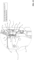
- FIGS 9-16 show the operation of the switch pole 1 during an opening manoeuvre.
- Figure 10 shows the switch pole with the movable contact assembly 6 in the first position P1 (closed condition of the switch pole).
- the first movable contacts 61 are coupled to the first fixed contacts 51 while the second movable contacts 62 are decoupled from the second fixed contacts 52.
- a pole current I can flow along the switch pole between the pole terminals 7, 8.
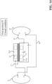
- the pole current I passes entirely through the first movable contacts 61 and the first fixed contacts 51 ( figure 14 ). No currents flow along the coil conductors 11, 12 as the second movable contacts 62 and the second fixed contacts 51 are decoupled.
- Figure 11 shows the switch pole with the movable contact assembly 6 in the first intermediate position P3, which is reached upon an initial slight movement of the movable contact assembly according to a rotation direction R about the rotation axis A1 ( figures 10-11 ).
- first movable contacts 61 are coupled to the first fixed contacts 51 and the second movable contacts 62 are coupled to the second fixed contacts 52.
- a pole current I can still flow between the pole terminals 7, 8.
- the pole current I is however split between a first current I1 passing through the first movable contacts 61 and the first fixed contacts 51 and a second current I2 passing through the second movable contacts 62, the second fixed contacts 52 and the first and second coil conductors 11, 12 ( figure 15 ).
- the second current I2 is very lower than the first current I1 as it circulates along a conductive path having a very higher equivalent resistance.
- the second current I2 circulating along the coil conductors 11, 12 generates a magnetic field B having a relatively small intensity.
- Figure 12 shows the switch pole with the movable contact assembly 6 in the second intermediate position P3, which is reached upon a further movement of the movable contact assembly according to a rotation direction R ( figures 11-12 ).
- the first movable contacts 61 are decoupled from the first fixed contacts 51 while the second movable contacts 62 are coupled to the second fixed contacts 52.
- a pole current I can still flow along the switch pole between the pole terminals 7, 8 as these latter are still short-circuited.
- the pole current I passes entirely through the second movable contacts 62, the second fixed contacts 52 and the coil conductors 11, 12 ( figure 16 ). No currents flow along the first movable contacts 61 and the first fixed contacts 51 as these latter are decoupled.
- the pole current I circulating along the coil conductors 11, 12 generates a magnetic field B having a relatively high intensity.
- the second pole terminal (and the movable contacts 61, 62) may have a positive voltage polarity while the first pole terminal 7 (and the fixed contacts 51, 52) may have a negative voltage polarity, or vice-versa). Since the dielectric distance between the movable contacts 61, 62 and the fixed contacts 51, 52 is quite short, electric arcs develop between the movable contact assembly 6 and the fixed contact assembly 5 under separation.
- the arc currents Iarc By flowing through the magnetic field generation arrangement 10, the arc currents Iarc generate a magnetic field B having a relatively high intensity, which displaces the electric arcs towards the arc-extinguishing region 4.
- Electric arcs are thus forced to pass through the arc-breaking plates 41 of the arc-chamber 40, which can therefore exert their arc-quenching action.
- the magnetic field generation arrangement 10 continues to generate a magnetic field B driving the electric arcs towards the arc extinguishing region 4 until said electric arcs are fully quenched.
- the magnetic field generation arrangement 10 can therefore be used also in AC applications.
- the intensity of the magnetic field B generated by the magnetic field generation arrangement 10 increases with the current and thus with the energy of the electric arcs.
- the magnetic field arrangement 10 can thus effectively operate even if the switch pole operates at relatively high voltages (e.g. up to 2,0 - 2,5 kV either AC or DC) and electric arcs with a huge energy content may therefore arise between the electric contacts under separation during an opening manoeuvre of the switch pole.
- the magnetic field generation arrangement 10 does not influence the operation of the switch pole in any way. At most, the magnetic field generation arrangement forms an alternative path for the pole current flowing along the switch pole.
- the magnetic field generation arrangement included in the switch pole it is possible to achieve an optimal utilization of the arc-breaking elements of the arc chamber, which are progressively involved in the arcing phenomena during an opening manoeuvre of the switching device.
- substantially all arc breaking plates of the arc chamber can be involved in the quenching action of electric arcs, thereby allowing a uniform and efficient utilization of the arc chamber. Less mechanical and thermal stresses are thus generated into the arc chamber with a consequent prolonged lifetime of this latter.
- the switch pole of the invention has a relatively simple and compact structure, relatively easy to manufacture at industrial level, at competitive costs compared to the currently available solutions on the market.
- the present invention relates also to a low-voltage switching device comprising at least a switch pole, according to the invention, as previously described.
- a switching device is a circuit breaker comprising three switch poles, according to the invention.
Landscapes
- Physics & Mathematics (AREA)
- Electromagnetism (AREA)
- Arc-Extinguishing Devices That Are Switches (AREA)
Abstract
A switch pole for a low-voltage switching device comprising:- an insulating casing defining an internal space with a contact region and an arc extinguishing region of said switch pole;- a first pole terminal and a second pole terminal couplable with corresponding line conductors of an electric line;- a fixed contact assembly and a movable contact assembly positioned in said contact region and including one or more fixed contacts and one or more movable contacts, respectively, which can be mutually coupled or uncoupled;- an arc chamber positioned in said arc extinguishing region and comprising a plurality of parallel arc-breaking plates;- a magnetic field generation arrangement configured to generate a magnetic field during an opening manoeuvre of the switch pole.
Description
- The present invention relates to a switch pole for a switching device suitable for installation in low-voltage electrical systems. The invention likewise relates to a switching device comprising one or more of said switch poles.
- Low-voltage switching devices, such as for example circuit breakers, disconnectors, contactors, or the like, comprise one or more switch poles, each including one or more fixed contacts and movable contacts that can be coupled to and uncoupled from one another.
- Switching devices of the known art also comprise driving means designed to move the movable contacts relative to said fixed contacts, so that these electric contacts can be mutually coupled or uncoupled, thereby allowing or preventing electric currents to flow along the switch poles. These driving means comprise, for instance, a number of mechanisms terminating in a shaft operatively connected to a movable contact assembly including the movable contacts.
- As is known, during an opening manoeuvre of a switching device, electric arcs may arise between the electric contacts under separation of the switch poles, particularly under stress conditions (e.g. in presence of overload currents or short-circuit currents).
- In order to break currents circulating along the switch poles, such arcing phenomena have to be extinguished as quickly as possible. To this aim, a switching device generally comprises, for each switch pole, an arc chamber including a number of arc-breaking elements positioned near the electric contacts and designed to split possible electric arcs arising between the electric contacts. Unfortunately, an uneven distribution of electric arcs among the arc-breaking elements of the arc chamber often occurs during the opening manoeuvre of a switch pole. As a result, the arc-quenching action exerted by the arc-breaking elements is not uniform and efficient, which may adversely affect the lifetime of the arc chamber itself and lead to an early decay of its functionalities, thereby remarkably limiting the overall performances of the switching device. Moreover, it has been seen that electric arcs may sometime strike towards other conductive parts of the switch pole, which are located outside the arc chamber of the switch pole. Obviously, the switch components possibly affected by these electric arcs may be subject to serious damages, since they are not generally designed to bear high electric and thermal stresses.
- The above-mentioned problems of the state of the art are even made more critical by the circumstance that, in modern electric power distribution grids, switching devices are often brought to operate to relatively high operating voltages (e.g. up to 2,0-2,5 kV either AC or DC). Electric arcs with a huge energy content may therefore arise between the electric contacts under separation during the opening manoeuvres of the switching device.
- The main purpose of the present invention is to provide a switch pole for low-voltage switching devices, which allows overcoming or mitigating the above-mentioned shortcomings.
- In particular, the present invention is aimed at providing a switch pole, in which electric arcs arising between the electric contacts under separation during the opening manoeuvres of the switching device develop uniformly along the arc chamber and are efficiently confined in the arc breaking region of the switch pole.
- A further object of the present invention is to provide a switch pole, in which arcing phenomena towards parts outside the arc-extinguishing region of the switch pole are prevented or remarkably reduced.
- A still further object of the present invention is to provide a switch pole reliable in operation and relatively easy and cheap to manufacture at industrial level.
- The above aims and purposes, as well as other purposes that will emerge clearly from the following description and attached drawings, are provided, according to the invention, by a switch pole for a low-voltage switching device, according to the following
claim 1 and the related dependent claims. In a general definition, the switch pole, according to the invention, comprises an insulating casing, which defines an internal space including a contact region and an arc extinguishing region. - The switch pole, according to the invention, comprises a first pole terminal and a second pole terminal configured to be coupled with corresponding line conductors of an electric line.
- The switch pole, according to the invention, comprises a fixed contact assembly arranged in said contact region and including a plurality of fixed electric contacts electrically connected to said first pole terminal. Said fixed electric contacts include one or more first fixed contacts and one or more second fixed contacts electrically insulated from said first fixed contacts.
- The switch pole, according to the invention, comprises a movable contact assembly arranged in said contact region and including a plurality of movable electric contacts electrically connected to said second pole terminal. Said movable electric contacts include one or more first movable contacts and one or more second movable contacts. Said movable contact assembly is reversibly movable around a rotation axis, so that said first movable contacts can be coupled to or decoupled from said first fixed contacts and said second movable contacts can be coupled to or decoupled from said second fixed contacts, when said movable contact assembly moves about said rotation axis.
- The switch pole, according to the invention, comprises an arc chamber arranged in said arc extinguishing region and comprising a plurality of arc-breaking elements.
- The switch pole, according to the invention, comprises a magnetic field generation arrangement including a first coil conductor and a second coil conductor wound around a winding axis parallel to the rotation axis of said movable contact assembly. Said first and second coil conductors are spaced one from another along said winding axis and are electrically connected in series between said second fixed contacts and said first pole terminal.
- The magnetic field generation arrangement is configured to generate a magnetic field during an opening manoeuvre of the switch pole. The magnetic field generated by said magnetic field generation arrangement is directed in such a way to make possible electric arcs, which arise between said fixed contact assembly and said movable contact assembly under separation during said opening manoeuvre, displace towards the arc extinguishing region of said switch pole. Preferably, said first and second coil conductors are arranged at opposite lateral walls of said insulating casing.
- According to an aspect of the invention, said first and second coil conductors comprise first and second coil terminals and third and fourth coil terminals respectively.
- The first coil terminal of said first coil conductor is electrically connected to said second fixed contacts through a first electric bus.
- The second coil terminal of said first coil conductor is electrically connected to the third coil terminal of said second coil conductor through a second electric bus.
- The fourth coil terminal of said second coil conductor is electrically connected to said first pole terminal through a third electric bus.
- According to an aspect of the invention, the switch pole comprises an additional casing structure to accommodate said first and second coil conductors and said first, second and third electric buses. Said additional casing structure is fixed to said insulating casing.
- According to an aspect of the invention, the switch pole comprises a magnetic shield arrangement combined with said magnetic field generation arrangement and located at an opposite side of the switch pole relative to said fixed contact assembly. Said magnetic field arrangement is configured to confine better the magnetic field generated by said magnetic field generation arrangement, during an opening manoeuvre of the switch pole, within the internal volume defined by the insulating casing.
- Preferably, the magnetic shield arrangement comprises a U-shaped magnetic yoke having a central portion, which is arranged at a front wall of said insulating casing, and a pair of lateral portions, which are arranged at opposite lateral walls of said insulating casing.
- Preferably, the central portion of said magnetic yoke is arranged on a first support fixed to said insulating casing at said front wall.
- Preferably, the lateral portions of said magnetic yoke are arranged on corresponding second supports fixed to said additional casing structure, at opposite lateral walls of said insulating casing. According to an aspect of the invention, said movable contact assembly is reversibly movable, about the aforesaid rotation axis, between a first position, which corresponds to a closed condition of said switch pole, and a second position, which corresponds to an open condition of said switch pole.
- When said movable contact assembly is in said first position:
- said first movable contacts are coupled to said first fixed contacts;
- said second movable contacts are decoupled from said second fixed contacts.
- When said movable contact assembly is in said second position:
- said first movable contacts are decoupled from said first fixed contacts;
- said second movable contacts are decoupled from said second fixed contacts.
- During an opening manoeuvre of said switch pole, said movable contact assembly moves from said first position to a first intermediate position, in which:
- said first movable contacts are coupled to said first fixed contacts;
- said second movable contacts are coupled to said second fixed contacts.
- During said opening manoeuvre, said movable contact assembly then moves from said first intermediate position to a second intermediate position, in which:
- said first movable contacts are decoupled from said first fixed contacts;
- said second movable contacts are coupled to said second fixed contacts.
- During said opening manoeuvre, said movable contact assembly then moves from said second intermediate position to said second position.
- In a further aspect, the present invention relates to a low-voltage switching device, preferably a circuit breaker, including at least a switch pole, according to invention, as described above. Further features and advantages of the present invention will be evident from the description of preferred but not exclusive embodiments of a switch pole, according to the invention, shown by way of examples in the accompanying drawings, wherein:
-
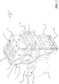
Figure 1 is a schematic view of the switch pole, according to the invention; -
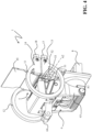
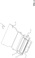
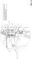
Figures 2-9 are additional schematic views of the switch pole, according to the invention; -
Figures 10-17 are schematic views showing the operation of the switch pole, according to the invention, during an opening manoeuvre. - With reference to the attached figures, the present invention relates to a
switch pole 1 for a low-voltage switching device, e.g. a circuit breaker, a disconnector, a contactor, or the like. - The switching device is particularly adapted for use in AC low-voltage electrical systems and it will be described with particular reference to these applications. However, in principle, it may be used also in electric systems of different type, e.g. in DC low-voltage electrical systems.
- For the purposes of the present invention, the term "low-voltage" typically relates to operating voltages up to 2,0 kV AC and 2,5 kV DC.
- The switching device comprises one or more switch poles, according to the invention.
- The number of switch poles may vary, according to the needs.
- In some embodiments, the switching device may be of the three-phase type and it comprises three switch poles. However, according to other embodiments of the invention, the switching device may include a different number of switch poles depending on the number of electric phases of the electric circuit, in which it has to be installed.
- According to the invention, the
switch pole 1 comprises an insulatingcasing 2 defining an internal volume including acontact region 3 and an arc extinguishing region 4 (figures 8-13 ). In general, thecontact region 3 is a portion of internal volume of the switch pole where the contact assemblies of the switch pole are arranged and operate. On the other hand, the arc-extinguishingregion 4 is a portion of internal volume of the switch pole where there are arranged arc-quenching means designed to extinguish possible electric arcs arising between the electric contacts of the switch pole, during the opening manoeuvres. - The
contact region 3 and thearc extinguishing region 4 are adjacent and in fluid-dynamic communication one with another. Preferably, thearc extinguishing region 4 is positioned at an upper level with respect to thecontact region 3, i.e. in proximal position relative to a top side of this latter. - For the sake of clarity, it is specified that relative terms used in this disclosure, e.g. "front", "rear", "lateral", "upper", "lower", "top" and "bottom" relate to the
switch pole 1 in its normal installation conditions, namely in the "vertical" installation (figure 1 ). - The insulating
casing 2 of the switch pole is shaped as a contoured box with opposite first and secondlateral walls rear walls bottom walls - Preferably, the insulating
casing 2 is formed by first and second half shells joined to each other. In this case, thetop wall 25 of the insulatingcasing 2 may be fixed to the insulating enclosure of another component (the arc chamber) of the switch pole and it may be removably installed in the switch pole together with such a component. However, according to other embodiments of the invention (not shown), the insulatingcasing 2 of the switch pole may be arranged differently. For example, thetop wall 25 may be integral with other walls of the insulating casing or it may be self-standing so as to be removably couplable with the remaining walls of the insulating casing. - Preferably, the
top wall 25 is provided with a number of through openings to allow the exit of hot gases from the internal space of the switch pole, in particular from thearc extinguishing region 4. The insulatingcasing 2 is made of an electrically insulating material, e.g. a thermosetting or thermoplastic material. - According to the invention, the
switch pole 1 comprises afirst pole terminal 7 and asecond pole terminal 8 couplable with corresponding line conductors of an electric line. - In operation, the
pole terminals - For the sake of clarity, it is specified that the terms "coupled", "decoupled" or "couplable" used in this disclosure relate to both an electrical and mechanical coupling/decoupling of different parts unless otherwise specified or self-evident from the description or figures.
- Preferably, the
pole terminals rear wall 24 of the insulating casing of the switch pole. - According to the invention, a
switch pole 1 comprises a fixedcontact assembly 5 and amovable contact assembly 6 arranged in thecontact region 3 of the switch pole. - The fixed
contact assembly 5 comprises one or more fixedelectric contacts first pole terminal 7. - More particularly, the fixed
contact assembly 5 includes one or more firstfixed contacts 51 and one or more secondfixed contacts 52, which are spaced apart from the fixedcontacts 51 and electrically insulated from these latter. - The first and second
fixed contacts first pole terminal 7 but they are mutually spaced and electrically insulated. - Preferably, the first and second
fixed contacts rear wall 24 of the insulating casing of the switch pole. - Preferably, the first and second
fixed contacts region 4 of the switch pole. - Preferably, the first
fixed contacts 51 are formed by a pair of conductive tips arranged on a firstconductive base 51A directly coupled to the first pole terminal 7 (figures 10-13 ). - Similarly, the second
fixed contacts 52 are preferably formed by a pair of conductive tips arranged on a secondconductive base 52A electrically connected to thefirst pole terminal 7 through other conductive components of the switch pole (figures 10-13 ) as it will better emerge from the following. - Preferably, the first and second
fixed contacts conductive bases fixed contacts 51 protrude at a greater height compared to the second fixed contacts 52 (figures 10-13 ). - Preferably, the fixed
contact assembly 5 comprises afirst spacer 53 of electrically insulating material interposed between the first and secondfixed contacts - Preferably, the fixed
contact assembly 5 comprises asecond spacer 54 of electrically insulating material interposed between thefirst pole terminal 7 and the secondfixed contacts 52 in order to prevent a direct electrical coupling between these components (which are electrically connected through other conductive components of the switch pole as it will better emerge from the following). - Preferably, the fixed
contact assembly 5 comprises an elongated conductive plate 55 (e.g. formed by a metal material) electrically connected to the secondfixed contacts 52. Theconductive plate 55 extends from the secondfixed contacts 52 towards thearc extinguishing region 4 and it is arranged at therear wall 24 of the insulatingcasing 2. - The
movable contact assembly 6 comprises one or more movableelectric contacts second pole terminal 8. - More particularly, the
movable contact assembly 6 includes one or more firstmovable contacts 61 and one or more second movable contacts 62 (figures 10-13 ). - Preferably, the first and second movable
electric contacts second pole terminal 8. - Preferably, the first and second
movable contacts region 4 of the switch pole, respectively. Preferably, the first and secondmovable contacts conductive head 65 electrically connected to thesecond pole terminal 8. - The
movable contact assembly 6 is reversibly movable around a rotation axis A1, which is preferably perpendicular to thelateral walls - Preferably, the
movable contact assembly 6 comprises a supportingstructure 63 for themovable contacts element 64, which protrudes outside the insulating casing of the switch pole (preferably from a suitable window of the front wall 23) for connection with a driving mechanism (not shown). - Preferably, the
conductive head 65 on which themovable contacts structure 63. Theconductive head 65 thus rotates together with the supportingstructure 63 and it can slightly tilt relative to said supporting structure, when this latter moves. In this way, when the supportingstructure 63 rotates according to a rotation direction, theconductive head 65 can tilt slightly with an opposite rotation movement relative to the supportingstructure 63. - The
movable contact assembly 6 is movable, about the rotation axis A1, between a first position P1 (figures 8 and10 ) and a second position P2 (figures 9 and13 ). In this way, the firstmovable contacts 61 can be coupled to or decoupled from the firstfixed contacts 51 while the secondmovable contacts 62 can be coupled to or decoupled from the secondfixed contacts 52. - The first position P1 of the
movable contact assembly 6 corresponds to a closed condition of the switch pole, in which electric currents are allowed to flow between the pole terminals of the switch pole, whereas the second position P2 of themovable contact assembly 6 corresponds to an open condition of the switch pole, in which electric currents flowing along the switch pole are interrupted. - Conveniently, the
movable contact assembly 6 moves between the first and second positions P1, P2 by rotating about the rotation axis A1 according to opposite rotation directions. A transition of themovable contact assembly 6 from the first position P1 to the second position P2 constitutes an opening manoeuvre of the switch pole whereas an opposite transition of themovable contact assembly 6 from the second position P2 to the first position P1 constitutes a closing manoeuvre of the switch pole. - According to an aspect of the invention, the
movable contact assembly 6 and the fixedcontact assembly 5 are arranged so that the first and secondmovable contacts fixed contacts figures 10-13 ). - When the
movable contact assembly 6 is the first position P1 (closed condition of the switch pole), the firstmovable contacts 61 are coupled to the firstfixed contacts 51 while the secondmovable contacts 62 are decoupled from the second fixed contacts 52 (figure 9 ). - During an opening manoeuvre of the switch pole, upon an initial movement according to a rotation direction R about the rotation axis A1 (
figures 10-11 ), themovable contact assembly 6 moves from the first position P1 to a first intermediate position P3 (figure 11 ), in which: - the first
movable contacts 61 are coupled to the firstfixed contacts 51; - the second
movable contacts 62 are coupled to the secondfixed contacts 52. - Upon a further movement according to the rotation direction R (
figures 11-12 ), themovable contact assembly 6 moves from the first intermediate position P3 to a second intermediate position P4 (figure 12 ), in which: - the first
movable contacts 61 are decoupled from the firstfixed contacts 51; - the second
movable contacts 62 are coupled to the secondfixed contacts 52. - Upon yet a further movement according to a rotation direction R (
figures 12-13 ), themovable contact assembly 6 moves from the second intermediate position P4 to the second position P2 (figure 13 ). - When the
movable contact assembly 6 is the second position P2, the firstmovable contacts 61 are decoupled from the firstfixed contacts 51 while the secondmovable contacts 62 are decoupled from the secondfixed contacts 52. - As it is evident from
figures 10-13 , the implementation of the above-described opening sequence of theelectric contacts movable contacts 61, 62 (which are mounted on the tilting head 65) and the special arrangement of the fixedcontacts 51, 52 (which protrude at different heights from the respectiveconductive bases - According to an aspect of the invention, the
movable contact assembly 6 and the fixedcontact assembly 5 are arranged so that the first and secondmovable contacts fixed contacts - Thus, starting from the second position P2, the
movable contact assembly 6 passes first through the second intermediate position P4 and then through the first intermediate position P3 before reaching the first position P1. - According to the invention, the
switch pole 1 comprises anarc chamber 40 positioned in thearc extinguishing region 4, conveniently above thecontact region 3. - The
arc chamber 40 comprises a plurality of arc-breakingelements 41 designed to extinguish possible electric arcs arising between theelectric contacts figures 10-13 ). - According to some embodiments, the
arc chamber 40 may be formed by a self-standing structure that can be removably installed in the corresponding switch pole. In this case, thearc chamber 40 comprises an insulating enclosure (made of an electrically insulating material, e.g. a thermosetting or thermoplastic material) removably fixable to the insulating casing of the switch pole. The arc-breakingelements 41 are conveniently fixed to said insulating enclosure (not shown). Preferably, thetop wall 25 of the insulating casing of the switch pole is fixed to said insulating enclosure, so that it can be installed or removed together with thearc chamber 40. - The arc-breaking
elements 41 of thearc chamber 40 include a series of arc-breaking plates arranged in parallel, preferably along reference planes parallel to the front andrear walls lateral walls casing 2. The arc-breakingplates 41 are preferably arranged at subsequent positions between the front andrear walls contact assembly 5. - Preferably, the arc-breaking
plates 41 are formed by contoured metallic or ceramic plates, which can have different dimensions and shapes according to the needs. - An essential aspect of the invention consists in that the
switch pole 1 comprises a magneticfield generation arrangement 10 configured to generate a magnetic field B, during an opening manoeuvre of the switch pole. - The magnetic
field generation arrangement 10 includes afirst coil conductor 11 and asecond coil conductor 12 wound around a winding axis A2 parallel to the rotation axis A1 of themovable contact assembly 6 and electrically connected mutually. - The first and
second coil conductors coil conductors - Preferably, the first and
second coil conductors lateral walls - As mentioned above, the first and
second coil conductors fixed contacts 52 and thefirst pole terminal 7 of the switch pole. - The first and
second coil conductors second coil terminals fourth coil terminals - According to an aspect of the invention:
- the
first coil terminal 13 of thefirst coil conductor 11 is electrically connected to the secondfixed contacts 52 through a firstelectric bus 17; - the
second coil terminal 14 of thefirst coil conductor 11 is electrically connected to thethird coil terminal 15 of thesecond coil conductor 12 through a secondelectric bus 18; - the
fourth coil terminal 16 of thesecond coil conductor 12 is electrically connected to thefirst pole terminal 7 through a thirdelectric bus 19. - In the embodiments shown in the cited figures, the first and
second coil conductors electric buses - The employment of
rigid conductors - According to alternative embodiments (not shown), however, each
coil conductor electric buses - As mentioned above, the winding axis A2 is parallel to the rotation axis of the
movable contact assembly 6. In this way, when a current circulates along thecoil conductors contact region 3 of the switch pole (basically according to a direction perpendicular to theopposite walls - Given that the
coil conductors contact region 3, the generated magnetic field B has field lines uniformly distributed across the transversal section of thecontact region 3. - Additionally, since the
coil conductors fixed contacts 52 and thefirst pole terminal 7, any current (AC or DC) flowing along thecoil conductors - By virtue of the generated magnetic field B, possible electric arcs arising between the
fixed contact assembly 5 and themovable contact assembly 6 under separation are affected by a magnetic force Fm (Lorentz force) directed towards the arc-extinguishingregion 4 of the switch pole. Such a magnetic force makes said electric arcs displace towards thearc extinguishing region 4. - In practice, possible electric arcs arising between the
fixed contact assembly 5 and themovable contact assembly 6 are "blown" by the generated magnetic field B towards thearc extinguishing region 4. They can thus distribute uniformly among the arc-breakingelements 41 of thearc chamber 40, which can efficiently exert their quenching action on them. - The magnetic field B generated by the magnetic
field generation arrangement 10 allows confining efficiently the electric arcs in thearc extinguishing region 4, thereby reducing the probability of re-strikes towards other conductive parts of the switch pole. - Preferably, the
switch pole 1 comprises anadditional casing structure 20 made of electrically insulating material and configured to accommodate the first andsecond coil conductors electric buses - Conveniently, the
additional casing structure 20 comprises a pair of insulating shells to enclose thecoil conductors electric buses - The
additional casing structure 20 is fixed to the insulatingcasing 2, conveniently at thelateral walls rear wall 24. - According to an aspect of the invention, the
switch pole 1 comprises a magnetic shield arrangement 9 combined with the magnetic field generation arrangement 10 (figures 3-4 ). - The magnetic shield arrangement 9 is configured to confine the magnetic field B generated by the magnetic
field generation arrangement 10, during an opening manoeuvre of the switch pole. - The magnetic shield arrangement 9 is located at an opposite side of the switch pole relative to the fixed
contact assembly 5. - Preferably, the magnetic shield arrangement 9 comprises a U-shaped magnetic yoke having a
central portion 91 arranged at thefront wall 23 of the insulatingcasing 2 and a pair oflateral portions 92 arranged at the oppositelateral walls - Preferably, the central and
lateral portions - Preferably, the central and
lateral portions - According to this embodiment, the
central portion 91 is arranged (e.g. glued) on afirst support 910 of electrically insulating material, which is fixed to the insulatingcasing 2 at thefront wall 23, while thelateral portions 92 are arranged (e.g. glued) on correspondingsecond supports 920 of electrically insulating material, which are fixed to theadditional casing structure 20 enclosing the magneticfield generation arrangement 10, at the oppositelateral walls casing 2. - It is evident from the above how the magnetic shield arrangement 9 allows confining better the generated magnetic field B within the internal volume defined by the insulating
casing 2, particularly limiting its expansion in the surrounding environment at thefrontal wall 23 of the insulating casing. -
Figures 9-16 show the operation of theswitch pole 1 during an opening manoeuvre. -
Figure 10 shows the switch pole with themovable contact assembly 6 in the first position P1 (closed condition of the switch pole). - In this situation, the first
movable contacts 61 are coupled to the firstfixed contacts 51 while the secondmovable contacts 62 are decoupled from the secondfixed contacts 52. - A pole current I can flow along the switch pole between the
pole terminals movable contacts 61 and the first fixed contacts 51 (figure 14 ). No currents flow along thecoil conductors movable contacts 62 and the secondfixed contacts 51 are decoupled. - No magnetic field is generated by the magnetic
field generation arrangement 10 as no currents flow along thecoil conductors - No electric arcs arise between the
movable contact assembly 6 and the fixedcontact assembly 5 as thepole terminals -
Figure 11 shows the switch pole with themovable contact assembly 6 in the first intermediate position P3, which is reached upon an initial slight movement of the movable contact assembly according to a rotation direction R about the rotation axis A1 (figures 10-11 ). - In this situation, the first
movable contacts 61 are coupled to the firstfixed contacts 51 and the secondmovable contacts 62 are coupled to the secondfixed contacts 52. - A pole current I can still flow between the
pole terminals movable contacts 61 and the firstfixed contacts 51 and a second current I2 passing through the secondmovable contacts 62, the secondfixed contacts 52 and the first andsecond coil conductors 11, 12 (figure 15 ). The second current I2 is very lower than the first current I1 as it circulates along a conductive path having a very higher equivalent resistance. - The second current I2 circulating along the
coil conductors - No electric arcs arise between the
movable contact assembly 6 and the fixedcontact assembly 5 as thepole terminals -
Figure 12 shows the switch pole with themovable contact assembly 6 in the second intermediate position P3, which is reached upon a further movement of the movable contact assembly according to a rotation direction R (figures 11-12 ). - In this situation, the first
movable contacts 61 are decoupled from the firstfixed contacts 51 while the secondmovable contacts 62 are coupled to the secondfixed contacts 52. - A pole current I can still flow along the switch pole between the
pole terminals movable contacts 62, the secondfixed contacts 52 and thecoil conductors 11, 12 (figure 16 ). No currents flow along the firstmovable contacts 61 and the firstfixed contacts 51 as these latter are decoupled. - The pole current I circulating along the
coil conductors - No electric arcs arise between the
movable contact assembly 6 and the fixedcontact assembly 5 as thepole terminals - Upon yet a further movement according to the rotation direction R (
figures 12-13 ), also the secondmovable contacts 62 decouple from the secondfixed contacts 52. - As the movable
electric contacts electric contacts second pole terminals movable contacts 61, 62) may have a positive voltage polarity while the first pole terminal 7 (and the fixedcontacts 51, 52) may have a negative voltage polarity, or vice-versa). Since the dielectric distance between themovable contacts contacts movable contact assembly 6 and the fixedcontact assembly 5 under separation. - The onset of these electric arcs allows arc currents Iarc to circulate along the
coil conductors pole terminals - By flowing through the magnetic
field generation arrangement 10, the arc currents Iarc generate a magnetic field B having a relatively high intensity, which displaces the electric arcs towards the arc-extinguishingregion 4. - Electric arcs are thus forced to pass through the arc-breaking
plates 41 of the arc-chamber 40, which can therefore exert their arc-quenching action. - Finally, when the
movable contact assembly 6 reaches the second position P2 (open condition of the switch pole), electric arcs may be finally quenched or continue their quenching process through the full extension of the arc-breakingelements 41. - However, the magnetic
field generation arrangement 10 continues to generate a magnetic field B driving the electric arcs towards thearc extinguishing region 4 until said electric arcs are fully quenched. - It is evidenced how the magnetic
field generation arrangement 10 exploits the energy provided by the electric arcs between themovable contact assembly 6 and the fixedcontact assembly 5 to generate the magnetic field B displacing the electric arcs. - This allows avoiding the installation of permanent magnets to blow the electric arcs towards arc-extinguishing
region 4. Differently from the solutions employing permanent magnets, the magneticfield generation arrangement 10 can therefore be used also in AC applications. - The intensity of the magnetic field B generated by the magnetic
field generation arrangement 10 increases with the current and thus with the energy of the electric arcs. In other words, the higher is the current of the electric arcs, the stronger is the driving action of the magnetic field B generated by the magneticfield generation arrangement 10. Themagnetic field arrangement 10 can thus effectively operate even if the switch pole operates at relatively high voltages (e.g. up to 2,0 - 2,5 kV either AC or DC) and electric arcs with a huge energy content may therefore arise between the electric contacts under separation during an opening manoeuvre of the switch pole. - On the other hand, in absence of electric arcs (e.g. at the early stages of the opening manoeuvre or during a closing manoeuvre or when the switch pole is in a closed condition, the magnetic
field generation arrangement 10 does not influence the operation of the switch pole in any way. At most, the magnetic field generation arrangement forms an alternative path for the pole current flowing along the switch pole. - The technical solutions adopted for the low-voltage switch pole, according to the present invention, allow the proposed aims and the objects to be achieved.
- By virtue of the magnetic field generation arrangement included in the switch pole, according to the present invention, it is possible to achieve an optimal utilization of the arc-breaking elements of the arc chamber, which are progressively involved in the arcing phenomena during an opening manoeuvre of the switching device. In particular, substantially all arc breaking plates of the arc chamber can be involved in the quenching action of electric arcs, thereby allowing a uniform and efficient utilization of the arc chamber. Less mechanical and thermal stresses are thus generated into the arc chamber with a consequent prolonged lifetime of this latter.
- Additionally, thanks to the magnetic field generation arrangement, the probability that electric arcs strike towards other conductive components of the switch pole, outside the arc-extinguishing region, is remarkably reduced.
- The switch pole of the invention has a relatively simple and compact structure, relatively easy to manufacture at industrial level, at competitive costs compared to the currently available solutions on the market.
- As mentioned above, the present invention relates also to a low-voltage switching device comprising at least a switch pole, according to the invention, as previously described. Preferably, such a switching device is a circuit breaker comprising three switch poles, according to the invention.
Claims (14)
- A switch pole (1) for a low-voltage switching device (100) comprising:- an insulating casing (2) defining an internal space with a contact region (3) and an arc extinguishing region (4) of said switch pole;- a first pole terminal (7) and a second pole terminal (8) couplable with corresponding line conductors of an electric line;- a fixed contact assembly (5) arranged in said contact region (3) and including a plurality of fixed electric contacts (51, 52) electrically connected to said first pole terminal (7), said fixed electric contacts including one or more first fixed contacts (51) and one or more second fixed contacts (52) electrically insulated from said first fixed contacts;- a movable contact assembly (6) arranged in said contact region (3) and including a plurality of movable electric contacts (61, 62) electrically connected to said second pole terminal (8), said movable electric contacts including one or more first movable contacts (61) and one or more second movable contacts (62), said movable contact assembly being reversibly movable around a rotation axis (A1), so that said first movable contacts (61) can be coupled to or decoupled from said first fixed contacts (51) and said second movable contacts (62) can be coupled to or decoupled from said second fixed contacts (52), when said movable contact assembly (6) moves about said rotation axis (A1);- an arc chamber (40) arranged in said arc extinguishing region (4) and comprising a plurality of arc-breaking elements (41);characterized in that said switch pole comprises a magnetic field generation arrangement (10) including a first coil conductor (11) and a second coil conductor (12) wound around a winding axis (A2) parallel to the rotation axis (A1) of said movable contact assembly (6), said first and second coil conductors (11, 12) being spaced one from another along said winding axis (A2) and being electrically connected in series between said second fixed contacts (52) and said first pole terminal (7),
wherein, said magnetic field generation arrangement (10) is configured to generate a magnetic field (B) during an opening manoeuvre of the switch pole, the generated magnetic field being directed in such a way to make electric arcs, which arise between said fixed contact assembly (5) and said movable contact assembly (6) under separation, displace towards the arc extinguishing region (4) of said switch pole. - Switch pole, according to claim 1, characterised in that said first and second coil conductors (11, 12) are arranged at opposite lateral walls (21, 22) of said insulating casing (2).
- Switch pole, according to one of the previous claims, characterised in that said first and second coil conductors (11, 12) comprise first and second coil terminals (13, 14) and third and fourth coil terminals (15, 16) respectively,wherein the first coil terminal (13) of said first coil conductor (11) is electrically connected to said second fixed contacts (52) through a first electric bus (17),wherein the second coil terminal (14) of said first coil conductor (11) is electrically connected to the third coil terminal (15) of said second coil conductor (12) through a second electric bus (18),wherein the fourth coil terminal (16) of said second coil conductor (12) is electrically connected to said first pole terminal (7) through a third electric bus (19).
- Switch pole, according to one of the previous claims, characterised in that said switch pole comprises an additional casing structure (20) to accommodate said first and second coil conductors (11) and said first, second and third electric buses (17, 18, 19), said additional casing structure being fixed to said insulating casing (2).
- Switch pole, according to one of the previous claims, characterised in that it comprises a magnetic shield arrangement (9) arranged at an opposite side of the switch pole relative to said fixed contact assembly (5), said magnetic shield arrangement being configured to confine the magnetic field generated by said magnetic field generation arrangement (10), during an opening manoeuvre of said switch pole.
- Switch pole, according to claim 5, characterised in that said magnetic shield arrangement (9) comprises a U-shaped magnetic yoke having a central magnetic portion (91) arranged at a front wall (23) of said insulating casing (2) and a pair of lateral magnetic portions (92) arranged at opposite lateral walls (21, 22) of said insulating casing (2).
- Switch pole, according to claim 3 and 6, characterised in that said central magnetic portion (91) is arranged on a first support (910) fixed to said insulating casing (2) at said front wall (23) and in that said second magnetic portions (92) are arranged on corresponding second supports (920) fixed to said additional casing structure (20), at opposite lateral walls (21, 22) of said insulating casing.
- Switch pole, according to one of the previous claims, characterised in that said movable contact assembly (6) is reversibly movable, about said rotation axis (A1), between a first position (P1), which corresponds to a closed condition of said switch pole, and a second position (P2), which corresponds to an open condition of said switch pole.
- Switch pole, according to claim 8, characterised in that, when said movable contact assembly (6) is in said first position (P1):- said first movable contacts (61) are coupled to said first fixed contacts (51);- said second movable contacts (62) are decoupled from said second fixed contacts (52).
- Switch pole, according to one of the claims from 8 to 9, characterised in that when said movable contact assembly (6) is in said second position (P2):- said first movable contacts (61) are decoupled from said first fixed contacts (51);- said second movable contacts (62) are decoupled from said second fixed contacts (52).
- Switch pole, according to claims 9 and 10, characterised in that, during an opening manoeuvre of said switch pole, said movable contact assembly (6) moves from said first position (P1) to a first intermediate position (P3), in which:- said first movable contacts (61) are coupled to said first fixed contacts (51);- said second movable contacts (62) are coupled to said second fixed contacts (52).
- Switch pole, according to claim 11, characterised in that, during an opening manoeuvre of said switch pole, said movable contact assembly (6) subsequently moves from said first intermediate position (P3) to a second intermediate position (P4), in which:- said first movable contacts (61) are decoupled from said first fixed contacts (51);- said second movable contacts (62) are coupled to said second fixed contacts (52).
- Switch pole, according to claim 12, characterised in that, during an opening manoeuvre of said switch pole, said movable contact assembly (6) subsequently moves from said second intermediate position (P4) to said second position (P2).
- A low-voltage switching device characterized in that it comprises at least a switch pole (1), according to one of the previous claims.
Priority Applications (4)
| Application Number | Priority Date | Filing Date | Title |
|---|---|---|---|
| EP23155404.9A EP4415014A1 (en) | 2023-02-07 | 2023-02-07 | Low-voltage switch pole |
| US18/426,655 US20240266127A1 (en) | 2023-02-07 | 2024-01-30 | Low-voltage switch pole |
| KR1020240016444A KR20240123758A (en) | 2023-02-07 | 2024-02-02 | Low-voltage switch pole |
| CN202410165620.4A CN118471712A (en) | 2023-02-07 | 2024-02-05 | Low-voltage switch pole |
Applications Claiming Priority (1)
| Application Number | Priority Date | Filing Date | Title |
|---|---|---|---|
| EP23155404.9A EP4415014A1 (en) | 2023-02-07 | 2023-02-07 | Low-voltage switch pole |
Publications (1)
| Publication Number | Publication Date |
|---|---|
| EP4415014A1 true EP4415014A1 (en) | 2024-08-14 |
Family
ID=85199548
Family Applications (1)
| Application Number | Title | Priority Date | Filing Date |
|---|---|---|---|
| EP23155404.9A Pending EP4415014A1 (en) | 2023-02-07 | 2023-02-07 | Low-voltage switch pole |
Country Status (4)
| Country | Link |
|---|---|
| US (1) | US20240266127A1 (en) |
| EP (1) | EP4415014A1 (en) |
| KR (1) | KR20240123758A (en) |
| CN (1) | CN118471712A (en) |
Citations (5)
| Publication number | Priority date | Publication date | Assignee | Title |
|---|---|---|---|---|
| DE143003C (en) * | 1902-04-02 | 1903-08-01 | Siemens Ag | ELECTRICAL SWITCH WITH FIXED AUXILIARY CONTACT FOR OPENING SPARK SENSING |
| US2555799A (en) * | 1947-02-05 | 1951-06-05 | Allis Chalmers Mfg Co | Electric switch |
| US3070681A (en) * | 1958-10-29 | 1962-12-25 | Ite Circuit Breaker Ltd | Face wound blowout coil |
| US3155801A (en) * | 1960-12-21 | 1964-11-03 | Ite Circuit Breaker Ltd | Arc chute side with encapsulated face wound blowout coil |
| CN114843159A (en) * | 2022-04-22 | 2022-08-02 | 江苏大全凯帆开关股份有限公司 | Direct current breaker static contact device with non-polarity magnetic blow |
Family Cites Families (4)
| Publication number | Priority date | Publication date | Assignee | Title |
|---|---|---|---|---|
| US3081389A (en) * | 1960-12-19 | 1963-03-12 | Ite Circuit Breaker Ltd | Uninterrupted arc chute venteng path for jump gap and runner |
| GB1297238A (en) * | 1970-02-12 | 1972-11-22 | ||
| EP1615247B1 (en) * | 2004-07-08 | 2008-09-03 | ABB Schweiz AG | Arc extinguishing device for circuit breaker |
| ES2645855T3 (en) * | 2015-01-23 | 2017-12-11 | Abb S.P.A. | Low voltage switch pole |
-
2023
- 2023-02-07 EP EP23155404.9A patent/EP4415014A1/en active Pending
-
2024
- 2024-01-30 US US18/426,655 patent/US20240266127A1/en active Pending
- 2024-02-02 KR KR1020240016444A patent/KR20240123758A/en active Pending
- 2024-02-05 CN CN202410165620.4A patent/CN118471712A/en active Pending
Patent Citations (5)
| Publication number | Priority date | Publication date | Assignee | Title |
|---|---|---|---|---|
| DE143003C (en) * | 1902-04-02 | 1903-08-01 | Siemens Ag | ELECTRICAL SWITCH WITH FIXED AUXILIARY CONTACT FOR OPENING SPARK SENSING |
| US2555799A (en) * | 1947-02-05 | 1951-06-05 | Allis Chalmers Mfg Co | Electric switch |
| US3070681A (en) * | 1958-10-29 | 1962-12-25 | Ite Circuit Breaker Ltd | Face wound blowout coil |
| US3155801A (en) * | 1960-12-21 | 1964-11-03 | Ite Circuit Breaker Ltd | Arc chute side with encapsulated face wound blowout coil |
| CN114843159A (en) * | 2022-04-22 | 2022-08-02 | 江苏大全凯帆开关股份有限公司 | Direct current breaker static contact device with non-polarity magnetic blow |
Also Published As
| Publication number | Publication date |
|---|---|
| US20240266127A1 (en) | 2024-08-08 |
| CN118471712A (en) | 2024-08-09 |
| KR20240123758A (en) | 2024-08-14 |
Similar Documents
| Publication | Publication Date | Title |
|---|---|---|
| EP3223293B1 (en) | Electrical switching apparatus, and arc chamber assembly and associated circuit protection method | |
| CN213184182U (en) | Switch electric appliance | |
| CN112543985A (en) | Switching device and method for operating a switching device | |
| KR20000008930A (en) | Electrode Structure for Vacuum Interrupter | |
| CN114551131A (en) | Direct current arc extinguishing device and motor type direct current switch equipment | |
| KR20140036111A (en) | Arc extinguishing mechanism of direct current switch and direct current switch and direct current circuit breaker having arc extinguishing mechanism | |
| KR20130000093U (en) | A circuit braker | |
| EP3734631B1 (en) | Dc circuit breaker | |
| CA1314579C (en) | Multiphase gas expansion circuit breaker for a gas-insulated metalclad cell | |
| US4525612A (en) | Gas insulated switch | |
| US2343323A (en) | Electric switch | |
| KR20210007390A (en) | Arc Extinguishing Unit of Molded Case Circuit Breaker | |
| EP4099522B1 (en) | Gas-insulated switchgear | |
| US20240266127A1 (en) | Low-voltage switch pole | |
| US20210035762A1 (en) | Device for door and phase segregation in molded case circuit breakers | |
| WO2025140151A1 (en) | Arc extinguishing structure of circuit breaker, and circuit breaker | |
| KR100297622B1 (en) | SF6 Gas-Insulated Switch Installation for Electricity Distribution Supply Networks | |
| KR102353017B1 (en) | Direct Current Circuit Breaker | |
| US12362113B2 (en) | Low voltage switch pole | |
| EP4641602A1 (en) | Switching apparatus for electrical systems | |
| EP4439603A1 (en) | Low voltage switch pole with a baffle arrangement | |
| US12444557B2 (en) | Low voltage switch pole | |
| US12087525B2 (en) | Low voltage switch pole | |
| CN216435773U (en) | Contact system, circuit breaker and isolator with increase magnetic component | |
| KR200413970Y1 (en) | Pole insulation guide of disconnector and earthing switch of gas insulated switchgear |
Legal Events
| Date | Code | Title | Description |
|---|---|---|---|
| PUAI | Public reference made under article 153(3) epc to a published international application that has entered the european phase |
Free format text: ORIGINAL CODE: 0009012 |
|
| STAA | Information on the status of an ep patent application or granted ep patent |
Free format text: STATUS: THE APPLICATION HAS BEEN PUBLISHED |
|
| AK | Designated contracting states |
Kind code of ref document: A1 Designated state(s): AL AT BE BG CH CY CZ DE DK EE ES FI FR GB GR HR HU IE IS IT LI LT LU LV MC ME MK MT NL NO PL PT RO RS SE SI SK SM TR |
|
| STAA | Information on the status of an ep patent application or granted ep patent |
Free format text: STATUS: REQUEST FOR EXAMINATION WAS MADE |
|
| 17P | Request for examination filed |
Effective date: 20250123 |