EP4414686A1 - Jig for assessing delayed fracture, method for assessing delayed fracture in sheared end surface, and test piece - Google Patents
Jig for assessing delayed fracture, method for assessing delayed fracture in sheared end surface, and test piece Download PDFInfo
- Publication number
- EP4414686A1 EP4414686A1 EP22892523.6A EP22892523A EP4414686A1 EP 4414686 A1 EP4414686 A1 EP 4414686A1 EP 22892523 A EP22892523 A EP 22892523A EP 4414686 A1 EP4414686 A1 EP 4414686A1
- Authority
- EP
- European Patent Office
- Prior art keywords
- test piece
- end surface
- pin
- delayed fracture
- assessing
- Prior art date
- Legal status (The legal status is an assumption and is not a legal conclusion. Google has not performed a legal analysis and makes no representation as to the accuracy of the status listed.)
- Pending
Links
Images





Classifications
-
- G—PHYSICS
- G01—MEASURING; TESTING
- G01N—INVESTIGATING OR ANALYSING MATERIALS BY DETERMINING THEIR CHEMICAL OR PHYSICAL PROPERTIES
- G01N3/00—Investigating strength properties of solid materials by application of mechanical stress
- G01N3/02—Details
- G01N3/04—Chucks
-
- G—PHYSICS
- G01—MEASURING; TESTING
- G01N—INVESTIGATING OR ANALYSING MATERIALS BY DETERMINING THEIR CHEMICAL OR PHYSICAL PROPERTIES
- G01N17/00—Investigating resistance of materials to the weather, to corrosion, or to light
-
- G—PHYSICS
- G01—MEASURING; TESTING
- G01N—INVESTIGATING OR ANALYSING MATERIALS BY DETERMINING THEIR CHEMICAL OR PHYSICAL PROPERTIES
- G01N3/00—Investigating strength properties of solid materials by application of mechanical stress
- G01N3/08—Investigating strength properties of solid materials by application of mechanical stress by applying steady tensile or compressive forces
-
- G—PHYSICS
- G01—MEASURING; TESTING
- G01N—INVESTIGATING OR ANALYSING MATERIALS BY DETERMINING THEIR CHEMICAL OR PHYSICAL PROPERTIES
- G01N17/00—Investigating resistance of materials to the weather, to corrosion, or to light
- G01N17/006—Investigating resistance of materials to the weather, to corrosion, or to light of metals
-
- G—PHYSICS
- G01—MEASURING; TESTING
- G01N—INVESTIGATING OR ANALYSING MATERIALS BY DETERMINING THEIR CHEMICAL OR PHYSICAL PROPERTIES
- G01N2203/00—Investigating strength properties of solid materials by application of mechanical stress
- G01N2203/0014—Type of force applied
- G01N2203/0016—Tensile or compressive
- G01N2203/0017—Tensile
-
- G—PHYSICS
- G01—MEASURING; TESTING
- G01N—INVESTIGATING OR ANALYSING MATERIALS BY DETERMINING THEIR CHEMICAL OR PHYSICAL PROPERTIES
- G01N2203/00—Investigating strength properties of solid materials by application of mechanical stress
- G01N2203/003—Generation of the force
- G01N2203/0032—Generation of the force using mechanical means
- G01N2203/0037—Generation of the force using mechanical means involving a rotating movement, e.g. gearing, cam, eccentric, or centrifuge effects
-
- G—PHYSICS
- G01—MEASURING; TESTING
- G01N—INVESTIGATING OR ANALYSING MATERIALS BY DETERMINING THEIR CHEMICAL OR PHYSICAL PROPERTIES
- G01N2203/00—Investigating strength properties of solid materials by application of mechanical stress
- G01N2203/0058—Kind of property studied
- G01N2203/006—Crack, flaws, fracture or rupture
- G01N2203/0067—Fracture or rupture
-
- G—PHYSICS
- G01—MEASURING; TESTING
- G01N—INVESTIGATING OR ANALYSING MATERIALS BY DETERMINING THEIR CHEMICAL OR PHYSICAL PROPERTIES
- G01N2203/00—Investigating strength properties of solid materials by application of mechanical stress
- G01N2203/02—Details not specific for a particular testing method
- G01N2203/022—Environment of the test
- G01N2203/0236—Other environments
-
- G—PHYSICS
- G01—MEASURING; TESTING
- G01N—INVESTIGATING OR ANALYSING MATERIALS BY DETERMINING THEIR CHEMICAL OR PHYSICAL PROPERTIES
- G01N2203/00—Investigating strength properties of solid materials by application of mechanical stress
- G01N2203/02—Details not specific for a particular testing method
- G01N2203/022—Environment of the test
- G01N2203/0236—Other environments
- G01N2203/024—Corrosive
-
- G—PHYSICS
- G01—MEASURING; TESTING
- G01N—INVESTIGATING OR ANALYSING MATERIALS BY DETERMINING THEIR CHEMICAL OR PHYSICAL PROPERTIES
- G01N2203/00—Investigating strength properties of solid materials by application of mechanical stress
- G01N2203/02—Details not specific for a particular testing method
- G01N2203/026—Specifications of the specimen
- G01N2203/0262—Shape of the specimen
- G01N2203/027—Specimens with holes or notches
-
- G—PHYSICS
- G01—MEASURING; TESTING
- G01N—INVESTIGATING OR ANALYSING MATERIALS BY DETERMINING THEIR CHEMICAL OR PHYSICAL PROPERTIES
- G01N2203/00—Investigating strength properties of solid materials by application of mechanical stress
- G01N2203/02—Details not specific for a particular testing method
- G01N2203/026—Specifications of the specimen
- G01N2203/0262—Shape of the specimen
- G01N2203/0278—Thin specimens
- G01N2203/0282—Two dimensional, e.g. tapes, webs, sheets, strips, disks or membranes
-
- G—PHYSICS
- G01—MEASURING; TESTING
- G01N—INVESTIGATING OR ANALYSING MATERIALS BY DETERMINING THEIR CHEMICAL OR PHYSICAL PROPERTIES
- G01N2203/00—Investigating strength properties of solid materials by application of mechanical stress
- G01N2203/02—Details not specific for a particular testing method
- G01N2203/04—Chucks, fixtures, jaws, holders or anvils
Definitions
- the present invention relates to a technology for assessing delayed fracture in a sheared end surface of a metal sheet in press forming.
- the present invention is a technology suitable for a delayed fracture assessment on a sheared end surface of a high-strength steel sheet having a tensile strength of 980 MPa or more.
- the present invention is a technology particularly suitable for assessment of automobile components.
- a high-strength steel sheet having a tensile strength of 980 MPa or more is used for the purpose of achieving both the weight reduction of a vehicle body and protection of an occupant in the event of a collision.
- an ultra-high-strength steel sheet having a tensile strength of 1470 MPa or more has been applied to the vehicle body.
- One of the problems in applying the high-strength steel sheet to the vehicle body is delayed fracture.
- delayed fracture occurred from an end surface (hereinafter, referred to as a sheared end surface) after a shearing process has become an important problem.
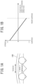
- FIG. 1B illustrates a stress distribution in the sheet thickness direction due to the bending deformation.
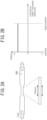
- FIG. 1B illustrates the stress distribution in the sheet thickness direction due to the uniaxial deformation.
- FIG. 3 is a diagram illustrating a schematic diagram of a stress-strain relationship in a case where the constant displacement restraint and constant load application are held for a sufficiently long time.
- the inventors applied a load to a high-strength steel sheet and compared a case where the restraint state is set to the constant displacement restraint with a case where the restraint state is set to the constant load application. Then, as a result of the examination by the inventors, it was found that the stress is relaxed as illustrated in FIG. 3 in the case of the constant displacement restraint even if the load stress at the start of the restraint is the same. Therefore, it was found that an apparent delayed fracture limit stress is higher in the case of the constant displacement restraint than in the case of the constant load application. As described in NPL 1, it is presumed that this is due to the effect of gradually creep deformation of high-strength steel when it is held under a constant stress even at room temperature. Further, as described in NPL 2, it is presumed that this is due to the effect of generation of stress relaxation in the case of constant displacement restraint.
- the stress load actually received by the actual automobile component is mainly the residual stress due to press forming. Therefore, the press-formed article as the automobile component is deformed into a certain shape and is held and used in that state. Therefore, it can be said that the constant displacement restraint is closer to a situation of the stress load received by the actual automobile component than in the case of being restrained by a constant load application after the load is applied.
- the methods of PTL 1 and PTL 2 are excellent methods for the load due to bending. That is, in the methods of PTL 1 and PTL 2, a load due to bending is applied to the sheared end surface, which is a straight portion of flat cutting, by constant displacement restraint. Accordingly, in the methods of PTL 1 and PTL 2, it is possible to assess the delayed fracture by applying a load close to uniform to the sheared end surface of a predetermined region.
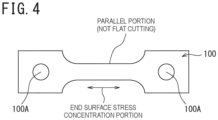
- FIG. 4 is a schematic view illustrating a shape of a tensile test piece 100 having pin holes 100A on the left and right, and a parallel portion to be applicable to a constant load test.
- the test piece 100 as illustrated in FIG. 4 is not processed for flat cutting even if a part of the sheared end surface is a straight line along a longitudinal direction. Therefore, in the test piece 100 as illustrated in FIG. 4 , it is difficult to assess a portion such as the straight portion of flat cutting.
- the sheared end surface cannot be formed by linear flat cutting, and it is necessary to perform shearing with a shear blade that has a curvature according to the notch. As a result, it is difficult to adjust the shear angle or the clearance when the test piece is produced.
- FIG. 5 is a view illustrating a rectangular-shaped test piece 100 having a sheared end surface of flat cutting.
- a uniaxial stress is applied by penetrating pins into pin holes formed on the left and right and displacing a portion between the pins. Then, the test piece 100 of FIG. 5 can be restrained in a state of being tensile-deformed. Further, a uniaxial stress can be applied by interposing the left and right both end portions of the test piece 100 with a chuck. When the uniaxial stress is applied in this way, at first glance, it seems that it is possible to assess the sheared end surface of the straight portion of flat cutting by the displacement restraint due to the uniaxial deformation.
- the material of the test piece is a high-strength steel sheet
- the following problems arise. That is, in practice, in a case where the pins are used, in the rectangular test piece 100 as illustrated in FIG. 5 , a tensile stress is applied to only a small part around the pin hole 100A (arrow portions in FIG. 5 ). Therefore, the test piece 100 does not have a uniform stress distribution along the longitudinal direction. Further, a case where the uniaxial stress is applied to the left and right both end portions of the test piece 100 made of the high-strength steel sheet by being interposed with the chuck is considered. In this case, correct assessment is difficult because the stress is concentrated on a portion of the end of the chuck (arrow portion in FIG. 5 ) or the chuck slips.
- the present invention has been made by paying attention to the above points, and an object of the present invention is to provide a jig and a test piece capable of assessing a delayed fracture in a sheared end surface more accurately and easily, and a method for assessing a delayed fracture using the same.
- the inventors obtained the following findings through various examinations.
- the sheared end surface formed on the test piece has a linear shape formed by flat cutting.
- the shear angle or the clearance which are conditions for shearing, can be easily adjusted.
- the test piece is effective to perform a delayed fracture assessment by applying a displacement restraint due to uniaxial deformation and applying a tensile stress as uniform as possible to the flat-cutting straight portion as much as possible on the test piece.
- the assessment is particularly effective for a metal sheet which is an automobile component or the like.
- the following phenomenon occurs in a case where a tensile load is simply applied through the left and right pin holes. That is, in a case where the test piece is a high-strength steel sheet, the stress is concentrated in a narrow range near the pin holes.
- the jig that realizes the displacement restraint by the uniaxial deformation with respect to the test piece is preferably a jig that can easily perform the uniaxial deformation and can be installed in a hydrogen intrusion environment.
- the jig that applies stress to the test piece and restrains the test piece in that state is made of a material of, for example, stainless steel or aluminum and the material is a dissimilar metal to the test piece will be considered.
- a corrosion current is generated for the test piece in a corrosive environment, and the hydrogen intrusion environment changes. Therefore, it is desirable that the test piece and the jig are electrically insulated.
- the cross section cut by flat cutting has an extension of the cross section on a straight line. Therefore, there is an advantage that it is easy to adjust a clearance or the like of the shear blade for forming the sheared end surface. In a case of a shape having non-parallel portions as in FIG. 4 , it is difficult to form the sheared end surface by flat cutting.
- one aspect of the present invention is a jig for assessing a delayed fracture configured to apply a tensile load along a longitudinal direction to a test piece made of a strip-shaped metal sheet having pin holes respective opened on both sides in the longitudinal direction, and restrain the test piece in a load state, and installed in a hydrogen intrusion environment together with the test piece, including a first pin configured to penetrate one pin hole of two pin holes formed in the test piece, and a second pin configured to penetrate the other pin hole; a frame component provided with first insertion holes into which respective both end portions of the first pin that penetrates the one pin hole is inserted; a slide component provided with second insertion holes into which respective both end portions of the second pin that penetrates the other pin hole is inserted; and a tensile force adjustment mechanism configured to connect the slide component to the frame component to be able to advance and retreat along the longitudinal direction of the test piece, in which the tensile force adjustment mechanism is a mechanism configured to advance and retreat the slide component by a
- an aspect of the present invention is a method for assessing a delayed fracture in a sheared end surface, the method includes attaching a test piece to the jig described in an aspect of the present invention; applying a tensile load to a sheared end surface of the test piece by advancing and retreating the slide component; and install the test piece in a hydrogen intrusion environment together with the jig in a load state.
- an aspect of the present invention is a test piece for assessing a delayed fracture in a sheared end surface, which is installed in a hydrogen intrusion environment in a state where a tensile load is applied along a longitudinal direction, in which the test piece is made of a high-strength steel sheet, and is strip-shaped with pin holes opened for applying a load to respective both sides in the longitudinal direction, one of end surfaces extending in the longitudinal direction is a sheared end surface extending on a straight line between at least two pin holes, in a region between the two pin holes, one or two or more lightened portions are provided, and each lightened portion is configured of an opening formed in the test piece, or a region with a reduced wall thickness, and the region is formed away from the sheared end surface.
- the jig of the aspect of the present invention can easily apply a tensile load to the test piece, and can be installed in a hydrogen intrusion environment to perform a test for delayed fracture assessment.
- test piece according to the aspect of the present invention is made of a high-strength steel sheet, the following effects are exhibited. That is, by the tensile load through the left and right pin holes, it is possible to apply a near-uniform tensile stress to a region longer than the conventional one in the sheared end surface. As a result, the jig of the aspect of the present invention can realize a test for delayed fracture assessment more accurately.
- the aspect of the present invention it becomes easy to predict the occurrence of delayed fracture when, for example, the high-strength steel sheet is applied to various components such as panel components, and structure/frame components of an automobile. According to the aspect of the present invention, a weight of an automobile body can be reduced by applying the high-strength steel sheet.
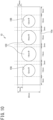
- the jig 1 for assessing the delayed fracture of the present embodiment is a jig for applying a tensile load along a longitudinal direction to a test piece 10.
- the jig 1 is a jig that restrains the test piece 10 in a load state, that is, in a constant displacement state.
- the jig 1 of the present embodiment is premised on being installed in a hydrogen intrusion environment together with the restrained test piece 10.
- test piece 10 is assumed to be a metal sheet formed of a strip-shaped metal sheet and having pin holes 10A and 10B opened each of on both sides in the longitudinal direction. A suitable shape of the test piece 10 will be described later.
- the jig 1 includes two pins 2 and 3, a frame component 5, a slide component 6, and a tensile force adjustment mechanism.
- Each of the two pins 2 and 3 penetrate any of the two pin holes 10A and 10B formed in the target test piece 10. That is, the two pins 2 and 3 are formed of the first pin 2 that penetrates one pin hole 10A and the second pin 3 that penetrates the other pin hole 10B.
- the pins 2 and 3 are not limited to cylindrical rods. It is sufficient that the pins 2 and 3 can penetrate the pin holes 10A and 10B and fix the test piece 10, and may be prismatic rods or the like. Contact surfaces of the pins 2 and 3 with the test piece 10 to be assessed are preferably insulated.
- the frame component 5 is formed with a first insertion hole for inserting each of both end portions of the first pin 2 that penetrates one pin hole 10A of the test piece 10.
- the frame component 5 of the present embodiment includes a frame-shaped structure that surrounds a space, in which the target test piece 10 is able to be disposed, by a pair of longitudinal members 5A and 5B, and a pair of lateral members 5C and 5D.
- the pair of longitudinal members 5A and 5B face each other in the sheet thickness direction of the test piece 10 with the target test piece 10 interposed therebetween.
- the pair of lateral members 5C and 5D face each other in the longitudinal direction of the test piece 10 with the test piece 10 interposed therebetween, and each connects end portions of the pair of longitudinal members 5A and 5B.
- the frame component 5 forms a rectangular frame.
- first insertion holes 5Aa and 5Ba are formed in each of the pair of longitudinal members 5A and 5B.
- the two first insertion holes 5Aa and 5Ba are formed coaxially with the pair of longitudinal members 5A and 5B in opposite directions.
- FIGS. 6 and 7 illustrate a case where the two first insertion holes 5Aa and 5Ba are both formed of through-holes.
- one of the first insertion holes 5Aa and 5Ba may be a bottomed hole.
- a width of a part of the pair of longitudinal members 5A and 5B along the longitudinal direction is smaller than the width of the test piece 10.
- the slide component 6 is formed with a second insertion hole for inserting each of both end portions of the second pin 3 that penetrates the other pin hole 10B of the test piece 10.
- the slide component 6 of the present embodiment is a component having a U-shaped cross section including a pair of foot portions 6A and 6B and root portion 6C that connects end portions of the foot portions 6A and 6B.
- the pair of foot portions 6A and 6B face each other in the sheet thickness direction of the test piece 10 with the second pin holes 10A and 10B of the target test piece 10 interposed therebetween.
- the slide component 6 is disposed in a space between the pair of longitudinal members 5A and 5B of the frame component 5 in use. At this time, a longitudinal direction of the pair of foot portions 6A and 6B, and a longitudinal direction of the pair of the longitudinal members 5A and 5B are disposed to be the same direction.
- a distance between outer surfaces of the pair of foot portions 6A and 6B is equal to or less than a facing distance between the pair of longitudinal members 5A and 5B.
- the outer surfaces of the pair of foot portions 6A and 6B may come into contact with inner surfaces of the pair of longitudinal members 5A and 5B, or may be in a non-contact state.
- the upper surface of the lower longitudinal direction member is a flat surface along the longitudinal direction.
- the upper surface of the lower longitudinal direction member is a guide surface that guides the slide component 6 in the longitudinal direction.
- the slide component 6 is disposed between the pair of longitudinal members 5A and 5B, and has a configuration in which the pair of longitudinal members 5A and 5B can advance and retreat in the longitudinal direction.
- the slide component 6 is installed in a space surrounded by the frame component 5, that is, in use.
- the root portion 6C is disposed to face one lateral member 5D (lateral member 5D on the right side in FIG. 6 ) in the longitudinal direction of the target test piece 10.
- second insertion holes 6Aa and 6Ba are formed in each of the pair of foot portions 6A and 6B.
- the second insertion holes 6Aa and 6Ba formed in each of the pair of foot portions 6A and 6B are both through-holes is illustrated.
- One of the two second insertion holes 6Aa and 6Ba may be a bottomed hole.
- the pair of longitudinal members 5A and 5B have long holes that are open through which the second pin 3 can penetrate.
- the long hole may not be provided.
- the tensile force adjustment mechanism is a mechanism for connecting the slide component 6 to the frame component 5 to be able to advance and retreat along the longitudinal direction of the test piece 10.
- the tensile force adjustment mechanism is configured of a feeding screw mechanism that moves linearly with rotation of a screw 7.
- the tensile force adjustment mechanism is a mechanism in which the slide component 6 advances and retreats with respect to the frame component 5.
- the tensile force adjustment mechanism includes a screw hole 6Ca of which a female thread is formed on an inner surface thereof and the screw 7 (bolt) screwed into the screw hole 6Ca, which configures the feeding screw mechanism.
- the screw hole 6Ca is a through-hole.
- the screw hole 6Ca is formed in the root portion 6C of the slide component 6 and penetrates the root portion 6C toward a shaft in the longitudinal direction of the test piece 10.
- a through-hole 5Da which is coaxial with the screw hole 6Ca, is opened in the lateral members 5C and 5D proximal to the root portion 6C.
- An opening area of the through-hole 5Da is smaller than a head portion of the screw 7, through which a shaft 7B of the screw 7 is able to pass.
- the screw shaft 7B of the screw 7 penetrates the through-hole 5Da and is screwed into the screw hole 6Ca from the outside of the lateral members 5C and 5D proximal thereto.
- a washer 8 is interposed between the outer surface of the proximal lateral member 5D and the head portion 7A of the screw 7.
- the screw hole 6Ca, the through-hole 5Da, and the screw 7 constitute the tensile force adjustment mechanism.
- a position of the screw hole 6Ca is displaced with respect to the screw shaft 7B by rotating the shaft of the screw 7.
- the slide component 6 advances and retreats with respect to the frame component 5 due to the displacement of the position.
- the configuration is such that a tensile force in the longitudinal direction can be applied to the target test piece 10 by advancing and retreating thereof.
- the contact surface of the jig 1 which comes into contact with the test piece 10 is configured to be electrically insulated from the test piece 10.
- the first pin 2 and the second pin 3 are made of an insulating material.
- an insulating coating film is formed to a surface of the surfaces of the first pin 2 and the second pin 3, which comes into contact with the test piece 10.
- the first method is a method in which an insulating material, for example, ceramics, a polymer, or the like is used for the pins 2 and 3.
- an insulating material for example, ceramics, a polymer, or the like is used for the pins 2 and 3.
- the pins 2 and 3 are subjected to a strong shear load from the test piece 10, there is a high possibility that the ceramics have a high risk of fracture and the polymer has an insufficient strength.
- the material of the pins 2 and 3 is preferably metal and has sufficient strength. Furthermore, since the jig 1 is placed in a hydrogen intrusion environment, as the material of the pins 2 and 3, stainless steel having sufficient corrosion resistance is the most appropriate. Therefore, it is effective to electrically insulate a contact portion between the test piece 10 and the stainless steel pins 2 and 3 by disposing the insulating coating film thereon.
- a tensile load is applied to the test piece 10 by the jig 1 of the present disclosure described above. Then, the test piece 10 having the sheared end surface that is displacement-restrained is installed under any hydrogen environment for any time. Then, the test piece 10 is determined whether the delayed fracture occurs according to the applied stress.
- the jig 1 applies a uniaxial tension to the test piece 10, and the test piece 10 can be restrained in the load state.
- the jig 1 since being placed under a hydrogen intrusion environment, the jig 1 needs to have sufficient corrosion resistance, and needs to have sufficient strength to apply a tensile stress. Therefore, the material of the jig 1 is preferably, for example, stainless steel.
- the test piece 10 of the present embodiment is made of a high-strength steel sheet and preferably has a sheared end surface extending along the longitudinal direction.
- FIG. 8 illustrates an example of a strip-shaped test piece shape that can be used in the present disclosure.
- a test piece A illustrated in FIG. 8A has a general test piece shape.
- the test piece A has a narrow gauge portion between the two pin holes 10A and 10B.
- a test piece B illustrated in FIG. 8B is a rectangular test piece 10 having an end portion extending in the longitudinal direction has a linear sheared end surface. Of the two end portions extending in the longitudinal direction, only one end portion may be used as the sheared surface. The other end portion may be a side for which dimensions such as the width of the test piece 10 are adjusted by cutting process or the like.
- the test piece B can easily adjust shearing conditions.
- a test piece C illustrated in FIG. 8C is an example of the most suitable test piece 10 in a case of being made of a high-strength steel sheet.
- test piece C is the same as that of the test piece B and has a rectangular shape. That is, the test piece C is the rectangular (strip-shaped) test piece 10 having a sheared end surface extending on a straight line along the longitudinal direction between the two pin holes 10A and 10B.
- test piece C has one or two or more lightened portions 10C for stress distribution adjustment in a region between the two pin holes 10A and 10B.
- the pin holes 10A and 10B, and the lightened portions 10C are formed by mechanical processing or discharge processing.
- the pin holes 10A and 10B, and the lightened portions 10C have small damage caused by the processing on the end surfaces thereof, and thereby the delayed fracture does not occur. Therefore, the delayed fracture occurs only in the sheared end surface portion. Therefore, only the stress distribution applied to the sheared end surface by the tension is important in the delayed fracture assessment.
- the tensile test piece 10 which is preferable in the present disclosure is the tensile test piece C which is capable of applying a uniform tensile stress to the linear sheared end surface.
- FIG. 9 illustrates an example of a stress distribution of sheared end surface in a case where tension is applied to the test piece C by the two pins 2 and 3.
- the test piece A it is possible to apply a uniform tensile stress to the sheared end surface thereof in the narrow width portion (gauge portion).
- the uniform stress portion of the sheared end surface is a region inside a curved concave region. Therefore, the test piece A is not easy to adjust the shearing conditions as in the linear sheared end surface.
- test piece A a dedicated shear die for producing the tensile test piece 10 is required.
- the test piece A cannot form the sheared end surface using a commonly used shearing machine. Therefore, the test piece A has a drawback that it is difficult to adjust a clearance or a shear angle of a blade of the shearing machine for assessment, and the like.
- the linear sheared end surface can be assessed.
- the test piece B applies the tensile stress only to a small region (portion indicated by an arrow in FIG. 8 ) directly below the pin holes 10A and 10B. Therefore, the test piece B can be assessed for the delayed fracture.
- the test piece B has a problem that the assessment result depends on a local shearing state at a location where the stress is concentrated and there is a concern about variation.
- the lightened portion 10C is used to adjust the strength distribution in the longitudinal direction in a region between the two pin holes 10A and 10B inside the both end surfaces.
- the stress is dispersed around a central portion of the test piece 10.
- it is possible to uniformly apply the tensile stress to a predetermined distance or more along the longitudinal direction in the sheared end surface extending linearly for flat cutting.
- the test piece C is capable of uniformly applying the tensile stress to the sheared end surface.
- the test piece C is a simple shape in which the outer peripheral contour shape of the test piece C is a rectangular shape similar to the test piece B, and the test piece 10 is easy to produce.
- the sheared surface of the test piece C has a linear shape of flat cutting, it is easy to adjust the shear conditions such as shear clearance. That is, the test piece C has a test piece shape that can easily form a sheared end surface under the shearing conditions according to the actual site.
- the lightened portion 10C is configured with an opening (through-hole) is illustrated.
- the lightened portion 10C may be formed by a method other than the opening.
- a wall thickness of a region where the opening is formed may be thinned by cutting or the like to form the lightened portion 10C.
- the lightened portions 10C may be formed by aligning two or more openings parallel in the width direction, in the longitudinal direction or by forming the openings in a staggered manner.
- the strength of the region between the left and right pin holes 10A and 10B in the test piece 10 along the longitudinal direction is reduced while keeping the sheared end surface linear.
- the strength of the portion where the lightened portion 10C is provided is reduced. Therefore, to lower the strength uniformly along the longitudinal direction, as described above, it is preferable to provide a plurality of lightened portions 10C along the longitudinal direction.
- the lightened portion 10C is adjusted to be formed, and thereby such a region is continuously formed by 3 mm or more along a longitudinal direction of the sheared end surface.
- the lightened portion 10C is formed away from the sheared end surface.
- the position closest to the sheared end surface of the lightened portion 10C is separated from the sheared end surface by 1 mm or more.
- a region (contour of the outer periphery) of each lightened portion 10C is not limited to a circular shape, and may have a polygonal shape such as an elliptical shape or a rectangular shape.
- each lightened portion 10C has a circular or elliptical shape without corners serving as a stress concentration portion.
- FIG. 9 illustrates an example of a stress distribution in the tensile deformation generated in the test piece 10 in a case where the CAE analysis is performed under the condition that the tensile force is applied to the test piece C through the two pin holes 10A and 10B.
- test piece C when the test piece C is used, it is possible to assess the linear sheared end surface. Moreover, the tensile stress can be applied relatively uniformly to a wide range of the sheared end surfaces.
- the stress is applied to the test piece 10 by applying the tensile force through the two pin holes 10A and 10B.
- the stress may be measured, for example, by attaching a strain gauge in the vicinity of the sheared end surface.
- the tensile strain which is applied to the sheared end surface of the test piece 10 is measured thereby capable of being easily obtained by comparing with a stress-strain curve of the assessment material.
- the relative positional relationship of the jig 1 and the tightening torque of the bolt or the like may be used as an index of the stress applied to the test piece 10.
- the test piece 10 As the strip-shaped test piece 10, the test piece 10 having the pin holes 10A and 10B opened on the left and right sides is used.
- the test piece 10 is attached to the jig 1 of the present disclosure. That is, the test piece 10 to be assessed is disposed in the space surrounded by the frame components 5. Then, the first pin 2 and the second pin 3 are inserted into the respective pin holes 10A and 10B, and the test piece 10 is attached to the jig 1. After this, by rotating the head portion of the nut, the slide component 6 is advanced and retreated, and the tensile load is applied to the sheared end surface of the test piece 10. By stopping the rotation of the head portion of the nut, the test piece 10 is restrained by the jig 1 in a constant displacement state to which tensile deformation is applied.
- the strain gauge may be attached to the vicinity of the sheared end surface of the test piece 10 to measure the strain of the sheared end surface. That is, the amount of strain is also measured together with the tensile force applied by the jig 1. The strain gauge is removed when the environment is set for hydrogen intrusion.
- test piece 10 is installed together with the jig 1 for a preset time with respect to the hydrogen intrusion environment set in advance.
- the situation of occurrence of cracks is assessed with the test piece 10 in this state.
- the hydrogen intrusion environment and the installation time are preferably set to conditions under which an amount of hydrogen intrusion equivalent to the amount of hydrogen, which is presumed to intrude under an environment where the material to be a target of assessment is actually used, is obtained.
- the installation of the test piece 10 under the hydrogen intrusion environment is performed, for example, by immersing the test piece 10 in a bath containing an acid solution such as hydrochloric acid or an aqueous NH 4 SCN solution.
- the concentration of the acid solution and the immersion time are set such that the amount of hydrogen set in advance as the allowable upper limit is a condition for intruding the test piece 10.
- the above test is executed by changing the condition of the tensile force applied to the jig 1.
- test piece 10 any of the test pieces A, B, and C as illustrated in FIG. 8 can be used in the jig 1 of the present disclosure.
- a test piece having the shape like the test piece C formed of the lightened portion 10C of the present disclosure is preferable.
- a known method can be applied to a basic method of the method for assessing the delayed fracture in the sheared end surface.
- the present disclosure may have the following configurations.
- test material A which is steel of a strength 1470 MPa class with a sheet thickness of 1.4 mm
- the present disclosure is not limited to the test material A.
- the present disclosure is applicable to metal materials including high-strength steel sheets having a tensile strength of 980 MPa or more such that the delayed fracture occurs on the sheared end surface.
- test material A was subjected to a shearing process to produce the test piece 10 to be assessed. That is, in the present example, the strip-shaped (rectangular shape) test piece 10 having a linear sheared end surface having a length of 80 mm ⁇ 30 mm was produced. The shear clearance during the shearing process was 12% with respect to the sheet thickness.
- the end surface of a portion not to be assessed was subjected to cutting process, leaving a sheared end surface on one side.
- the lower end surface was left as the sheared end surface.
- the upper end surface side was subjected to cutting process to adjust the width of the test piece 10 to a desired width.
- the pin holes 10A and 10B, and the holes (lightened portions 10C) for adjusting the stress distribution on the end surface were opened and produced by cutting process to the test piece 10.
- a strain gauge was attached to the test piece 10 in the vicinity of a location where the tensile stress on the sheared end surface is presumed to be maximum.
- test pieces 10 as described above were prepared.
- each of the test pieces 10 was attached to the jig 1 (see FIGS. 6 and 7 ) of the present embodiment. Then, the tensile load was applied to the test piece 10 by tightening the nut, and the test piece 10 was displacement-restrained.
- FIG. 10 illustrates the test piece 10 having the shape of FIG. 10 .
- CAE analysis was performed under the condition that the sheared end surface thereof receives a tensile stress of about a yield stress (YS) of the uniaxial tension.
- FIG. 11 illustrates the stress distribution in the tensile direction generated on the test piece 10 based on the analysis.
- FIG. 12 illustrates the stress distribution of the flat-cutting sheared end surface under various load stresses by changing the tightening amount (tensile load) of the nut.
- FIG. 10 illustrates the stress distribution in the tensile direction of the flat-cutting sheared end surface from an end surface of 22 mm to an end surface position of 73 mm in the longitudinal direction.
- the lightened portion 10C is disposed around the vicinity of the peak of the stress.
- the lightened portion 10C is provided as illustrated in FIG. 10 .
- a region having the uniaxial tensile stress of 70% or more of the maximum reached stress is formed in a wide region along the extending direction of the sheared end surface.
- FIG. 12 it was confirmed that the region could be applied over a region of at least 3 mm or more.
- Example 2 in the same manner as in Example 1, the jig 1 of the present embodiment was used to apply the stress to the test piece 10 having the above-described shape by tightening the screw 7.
- the strain gauge was attached to a location where the stress load of the flat-cutting sheared end surface portion was maximum. Then, the nut was tightened while observing a strain value measured by the strain gauge to adjust an amount of strain. Then, with reference to the stress-strain curve of the test material A, tightening was stopped when the amount of strain is such that the maximum reached stress on the flat-cutting sheared end surface becomes the target stress.
- the pins 2 and 3 were made of stainless steel.
- the contact portions between pins 2 and 3, and the test piece 10 were insulated by wrapping the Teflon tape around the surfaces of pins 2 and 3 to coat them.
- conduction between the pins 2 and 3, and the test piece 10 was confirmed by a tester. According to this confirmation, electricity was conductive in a case where the Teflon tape was not coated.
- insulation was provided even in a case where the tensile load was applied.
- Example 3 the assessment was performed in a case where the pins 2 and 3 were not covered with the Teflon tape, that is, in a case where there is no insulation between the pins 2 and 3, and the test piece 10.
- Example 3 was assessed under the same conditions as Example 2 except that the pins 2 and 3 were not coated with the Teflon tape.
- pins 2 and 3 were each assessed in cases where the Teflon tape was used and was not used.
- Example 2 the test piece 10 to which the tensile force (load stress) was applied by tightening the screw 7 was immersed in hydrochloric acid at pH 2 for 96 hours together with the jig 1 in the same manner as in Example 1. Then, the delayed fracture with respect to the magnitude of the load stress was assessed.
- the assessment of the occurrence of the delayed fracture was determined as OK when there was no "sheet thickness penetration of crack” and NG when there was.
- the crack was determined by confirming that the crack was generated and advanced during the delayed fracture test by a camera provided vertically above the jig 1 that restrains the test piece 10.
- Table 1 illustrates assessment results in Example 2.
- Table 2 illustrates assessment results in Example 3.
- the delayed fracture limit stress of the test piece 10 under the hydrogen intrusion environment was 600 MPa in a case of being insulated with the Teflon tape.
- the delayed fracture limit stress was 1000 MPa in a case of not being insulated with the Teflon tape.
- the assessment differs depending on the presence or absence of insulation. That is, it was found that, by insulating the test piece 10, and the pins 2 and 3, the influence of the change in the delayed fracture limit stress due to the contact between dissimilar metals can be eliminated.
- the delayed fracture limit stress is around 600 MPa under the above conditions.
- Example 3 which was not insulated is as follows. That is, in the state where the insulation is not performed, the blank (test piece 10), which is an electrically base low carbon steel, comes into contact with the electrically noble stainless steel (jig 1). As a result, the blank side becomes an anode-polarized state and the generation and intrusion of hydrogen are suppressed, which is presumed to be due to the suppression of the delayed fracture. However, in a situation where stress corrosion cracking is predominant, there is also a possibility that fracture is promoted conversely.
Landscapes
- Life Sciences & Earth Sciences (AREA)
- General Health & Medical Sciences (AREA)
- Immunology (AREA)
- Chemical & Material Sciences (AREA)
- Analytical Chemistry (AREA)
- Biochemistry (AREA)
- Physics & Mathematics (AREA)
- General Physics & Mathematics (AREA)
- Health & Medical Sciences (AREA)
- Pathology (AREA)
- Biodiversity & Conservation Biology (AREA)
- Ecology (AREA)
- Environmental & Geological Engineering (AREA)
- Environmental Sciences (AREA)
- Investigating Strength Of Materials By Application Of Mechanical Stress (AREA)
Abstract
Description
- The present invention relates to a technology for assessing delayed fracture in a sheared end surface of a metal sheet in press forming. The present invention is a technology suitable for a delayed fracture assessment on a sheared end surface of a high-strength steel sheet having a tensile strength of 980 MPa or more. In addition, the present invention is a technology particularly suitable for assessment of automobile components.
- At present, automobiles are required to improve fuel efficiency and collision safety by reducing a weight. A high-strength steel sheet having a tensile strength of 980 MPa or more is used for the purpose of achieving both the weight reduction of a vehicle body and protection of an occupant in the event of a collision. In recent years, particularly, an ultra-high-strength steel sheet having a tensile strength of 1470 MPa or more has been applied to the vehicle body. One of the problems in applying the high-strength steel sheet to the vehicle body is delayed fracture. Particularly, in the ultra-high-strength steel sheet, delayed fracture occurred from an end surface (hereinafter, referred to as a sheared end surface) after a shearing process has become an important problem.
- It is known that a large tensile stress remains on the sheared end surface. For this reason, there is a concern that delayed fracture occurs on the sheared end surfaces after press forming.
- Here, it is known that the delayed fracture in the sheared end surface is further promoted by applying an external stress. Then, there are test methods (
PTL 1 and PTL 2) in which a stress is applied by a constant displacement restraint due to bending deformation, for example, to assess delayed fracture in the sheared end surface. Further, as another test method, a test has been proposed in which stress is applied by constant load application due to uniaxial deformation (PTL 3). -
- PTL 1:
JP6380423 B - PTL 2:
JP5971058 B - PTL 3:
JP6354476 B - Non Patent Literature
- NPL 1: Cheng Liu, Ping Liu, Zhenbo Zhao and Derek O. Northwood: Room temperature creep of a high strength steel, Materials and Design, 22 (2001) 325-328.
- NPL 2: K. Harihara, O. Majidi, C. Kim, M.G. Lee and F. Barlet: Stress relaxation and its effect on tensile deformation of steels, Materials and Design, 52 (2013) 284-288.
- The inventors compared uniaxial deformation (see
FIG. 2A ) and bending deformation (seeFIG. 1A ) under the same stress load conditions. As a result of intensive examinations by the inventors, it has been found that, even with the same stress load, a critical stress at which delayed fracture does not occur in the sheared end surfaces may be lower in the uniaxial deformation. The reason is that in the bending deformation, a stress gradient exists in a sheet thickness direction as compared with the uniaxial deformation. Therefore, it is presumed that this is because the crack growth of the delayed fracture is suppressed in the bending deformation. Here,FIG. 1B illustrates a stress distribution in the sheet thickness direction due to the bending deformation.FIG. 1B illustrates the stress distribution in the sheet thickness direction due to the uniaxial deformation. - Further,
FIG. 3 is a diagram illustrating a schematic diagram of a stress-strain relationship in a case where the constant displacement restraint and constant load application are held for a sufficiently long time. - The inventors applied a load to a high-strength steel sheet and compared a case where the restraint state is set to the constant displacement restraint with a case where the restraint state is set to the constant load application. Then, as a result of the examination by the inventors, it was found that the stress is relaxed as illustrated in
FIG. 3 in the case of the constant displacement restraint even if the load stress at the start of the restraint is the same. Therefore, it was found that an apparent delayed fracture limit stress is higher in the case of the constant displacement restraint than in the case of the constant load application. As described inNPL 1, it is presumed that this is due to the effect of gradually creep deformation of high-strength steel when it is held under a constant stress even at room temperature. Further, as described inNPL 2, it is presumed that this is due to the effect of generation of stress relaxation in the case of constant displacement restraint. - Further, in a case of considering the assessment of the delayed fracture in the sheared end surface in the press-formed article used as an automobile component, the stress load actually received by the actual automobile component is mainly the residual stress due to press forming. Therefore, the press-formed article as the automobile component is deformed into a certain shape and is held and used in that state. Therefore, it can be said that the constant displacement restraint is closer to a situation of the stress load received by the actual automobile component than in the case of being restrained by a constant load application after the load is applied.
- In that respect, it can be said that the methods of
PTL 1 andPTL 2 are excellent methods for the load due to bending. That is, in the methods ofPTL 1 andPTL 2, a load due to bending is applied to the sheared end surface, which is a straight portion of flat cutting, by constant displacement restraint. Accordingly, in the methods ofPTL 1 andPTL 2, it is possible to assess the delayed fracture by applying a load close to uniform to the sheared end surface of a predetermined region. - On the other hand, it has been found that there are some difficult points in the assessment of the straight portion of flat cutting in the displacement restraint due to the uniaxial deformation by the conventional methods. For example,
PTL 3 adopts a load on atest piece 100 by a constant load using a pin. However, in thetest piece 100, a width of the region between pin holes is narrowed, and thereby the stress is the highest. However, since the plate width must be small at that location, a notch is made or the like. - In addition, most portions of the sheared end surfaces of the automobile components are not curved portions but straight portions of flat cutting produced by linear shearing. Therefore, the method for assessing a delayed fracture in which a stress is applied to the sheared end surface which is the straight portion of flat cutting is the most important.
- In addition, in a case where flat cutting is adopted, it means that a shear angle can be added and a clearance can be adjusted, which is preferable for a more practical examination.
-
FIG. 4 is a schematic view illustrating a shape of atensile test piece 100 havingpin holes 100A on the left and right, and a parallel portion to be applicable to a constant load test. However, thetest piece 100 as illustrated inFIG. 4 is not processed for flat cutting even if a part of the sheared end surface is a straight line along a longitudinal direction. Therefore, in thetest piece 100 as illustrated inFIG. 4 , it is difficult to assess a portion such as the straight portion of flat cutting. For example, the sheared end surface cannot be formed by linear flat cutting, and it is necessary to perform shearing with a shear blade that has a curvature according to the notch. As a result, it is difficult to adjust the shear angle or the clearance when the test piece is produced. -
FIG. 5 is a view illustrating a rectangular-shaped test piece 100 having a sheared end surface of flat cutting. In thetest piece 100 ofFIG. 5 , a uniaxial stress is applied by penetrating pins into pin holes formed on the left and right and displacing a portion between the pins. Then, thetest piece 100 ofFIG. 5 can be restrained in a state of being tensile-deformed. Further, a uniaxial stress can be applied by interposing the left and right both end portions of thetest piece 100 with a chuck. When the uniaxial stress is applied in this way, at first glance, it seems that it is possible to assess the sheared end surface of the straight portion of flat cutting by the displacement restraint due to the uniaxial deformation. - However, assuming a case where the material of the test piece is a high-strength steel sheet, the following problems arise. That is, in practice, in a case where the pins are used, in the
rectangular test piece 100 as illustrated inFIG. 5 , a tensile stress is applied to only a small part around thepin hole 100A (arrow portions inFIG. 5 ). Therefore, thetest piece 100 does not have a uniform stress distribution along the longitudinal direction. Further, a case where the uniaxial stress is applied to the left and right both end portions of thetest piece 100 made of the high-strength steel sheet by being interposed with the chuck is considered. In this case, correct assessment is difficult because the stress is concentrated on a portion of the end of the chuck (arrow portion inFIG. 5 ) or the chuck slips. - The present invention has been made by paying attention to the above points, and an object of the present invention is to provide a jig and a test piece capable of assessing a delayed fracture in a sheared end surface more accurately and easily, and a method for assessing a delayed fracture using the same.
- As described above, there is a concern about a delayed fracture occurred from the sheared end surface of the high-strength steel sheet.
- The inventors obtained the following findings through various examinations.
- It is preferable that the sheared end surface formed on the test piece has a linear shape formed by flat cutting. In the case of producing the linear sheared end surface, since it is sufficient to use the linear shear blade, the shear angle or the clearance, which are conditions for shearing, can be easily adjusted.
- In addition, in the case of the high-strength steel sheet, it is preferable to apply the tensile load through the left and right pin holes rather than applying the tensile load with the chuck.
- Further, it is effective to perform a delayed fracture assessment by applying a displacement restraint due to uniaxial deformation and applying a tensile stress as uniform as possible to the flat-cutting straight portion as much as possible on the test piece. The assessment is particularly effective for a metal sheet which is an automobile component or the like. However, for a target test piece having a linear sheared end surface at least in a region between the pin holes, the following phenomenon occurs in a case where a tensile load is simply applied through the left and right pin holes. That is, in a case where the test piece is a high-strength steel sheet, the stress is concentrated in a narrow range near the pin holes.
- Further, the jig that realizes the displacement restraint by the uniaxial deformation with respect to the test piece is preferably a jig that can easily perform the uniaxial deformation and can be installed in a hydrogen intrusion environment.
- At this time, a case where the jig that applies stress to the test piece and restrains the test piece in that state is made of a material of, for example, stainless steel or aluminum and the material is a dissimilar metal to the test piece will be considered. In this case, a corrosion current is generated for the test piece in a corrosive environment, and the hydrogen intrusion environment changes. Therefore, it is desirable that the test piece and the jig are electrically insulated.
- In the present disclosure, on the premise of such findings, a simple jig, a test piece shape, and an assessment method using the same to realize the findings are considered.
- The cross section cut by flat cutting has an extension of the cross section on a straight line. Therefore, there is an advantage that it is easy to adjust a clearance or the like of the shear blade for forming the sheared end surface. In a case of a shape having non-parallel portions as in
FIG. 4 , it is difficult to form the sheared end surface by flat cutting. - Then, to solve the problem, one aspect of the present invention is a jig for assessing a delayed fracture configured to apply a tensile load along a longitudinal direction to a test piece made of a strip-shaped metal sheet having pin holes respective opened on both sides in the longitudinal direction, and restrain the test piece in a load state, and installed in a hydrogen intrusion environment together with the test piece, including a first pin configured to penetrate one pin hole of two pin holes formed in the test piece, and a second pin configured to penetrate the other pin hole; a frame component provided with first insertion holes into which respective both end portions of the first pin that penetrates the one pin hole is inserted; a slide component provided with second insertion holes into which respective both end portions of the second pin that penetrates the other pin hole is inserted; and a tensile force adjustment mechanism configured to connect the slide component to the frame component to be able to advance and retreat along the longitudinal direction of the test piece, in which the tensile force adjustment mechanism is a mechanism configured to advance and retreat the slide component by a feeding screw mechanism moving linearly with rotation of a screw.
- Further, an aspect of the present invention is a method for assessing a delayed fracture in a sheared end surface, the method includes attaching a test piece to the jig described in an aspect of the present invention; applying a tensile load to a sheared end surface of the test piece by advancing and retreating the slide component; and install the test piece in a hydrogen intrusion environment together with the jig in a load state.
- Further, an aspect of the present invention is a test piece for assessing a delayed fracture in a sheared end surface, which is installed in a hydrogen intrusion environment in a state where a tensile load is applied along a longitudinal direction, in which the test piece is made of a high-strength steel sheet, and is strip-shaped with pin holes opened for applying a load to respective both sides in the longitudinal direction, one of end surfaces extending in the longitudinal direction is a sheared end surface extending on a straight line between at least two pin holes, in a region between the two pin holes, one or two or more lightened portions are provided, and each lightened portion is configured of an opening formed in the test piece, or a region with a reduced wall thickness, and the region is formed away from the sheared end surface.
- The jig of the aspect of the present invention can easily apply a tensile load to the test piece, and can be installed in a hydrogen intrusion environment to perform a test for delayed fracture assessment.
- In addition, even if the test piece according to the aspect of the present invention is made of a high-strength steel sheet, the following effects are exhibited. That is, by the tensile load through the left and right pin holes, it is possible to apply a near-uniform tensile stress to a region longer than the conventional one in the sheared end surface. As a result, the jig of the aspect of the present invention can realize a test for delayed fracture assessment more accurately.
- In addition, according to the aspect of the present invention, it becomes easy to predict the occurrence of delayed fracture when, for example, the high-strength steel sheet is applied to various components such as panel components, and structure/frame components of an automobile. According to the aspect of the present invention, a weight of an automobile body can be reduced by applying the high-strength steel sheet.
-
-
FIG. 1 is a diagram illustrating an example of bending deformation and an example of a stress distribution on an end surface of a test piece due to the bending deformation; -
FIG. 2 is a diagram illustrating an example of a load of uniaxial deformation and an example of a stress distribution on an end surface of a test piece due to the uniaxial deformation; -
FIG. 3 is a diagram comparing a stress-strain relationship in a case of constant displacement restraint and constant load application; -
FIG. 4 is a schematic view illustrating a tensile test piece having a general parallel portion; -
FIG. 5 is a schematic view of a case where a pin hole is drilled and a case where a gripping portion of a chuck is provided for a rectangular-shaped test piece having a sheared end surface of flat cutting; -
FIG. 6 is a perspective view of a jig that applies uniaxial tension to a test piece to fix (restrain) the test piece; -
FIG. 7 is a side sectional view of the jig; -
FIG. 8 is a diagram illustrating an example of a test piece shape that can be assessed with the jig of the present disclosure; -
FIG. 9 is a diagram illustrating an example of a stress distribution when the pin is pulled in a shape of a test piece C; -
FIG. 10 is a view illustrating a shape of the test piece in an example; -
FIG. 11 is a diagram illustrating the stress distribution in a test piece when applying a load of about a yield stress in an example; and -
FIG. 12 is a diagram illustrating a stress distribution of a sheared end surface portion formed of flat cutting when a tightening amount (tensile load) of a screw is changed. - Next, embodiments of the present invention will be described with reference to the drawings.
- As illustrated in
FIGS. 6 and7 , thejig 1 for assessing the delayed fracture of the present embodiment is a jig for applying a tensile load along a longitudinal direction to atest piece 10. Thejig 1 is a jig that restrains thetest piece 10 in a load state, that is, in a constant displacement state. Furthermore, thejig 1 of the present embodiment is premised on being installed in a hydrogen intrusion environment together with the restrainedtest piece 10. - Further, in the present embodiment, the
test piece 10 is assumed to be a metal sheet formed of a strip-shaped metal sheet and havingpin holes test piece 10 will be described later. - As illustrated in
FIGS. 6 and7 , thejig 1 according to the present embodiment includes twopins frame component 5, aslide component 6, and a tensile force adjustment mechanism. - Each of the two
pins pin holes target test piece 10. That is, the twopins first pin 2 that penetrates onepin hole 10A and thesecond pin 3 that penetrates theother pin hole 10B. - The
pins pins test piece 10, and may be prismatic rods or the like. Contact surfaces of thepins test piece 10 to be assessed are preferably insulated. - The
frame component 5 is formed with a first insertion hole for inserting each of both end portions of thefirst pin 2 that penetrates onepin hole 10A of thetest piece 10. - The
frame component 5 of the present embodiment includes a frame-shaped structure that surrounds a space, in which thetarget test piece 10 is able to be disposed, by a pair oflongitudinal members lateral members longitudinal members test piece 10 with thetarget test piece 10 interposed therebetween. In addition, the pair oflateral members test piece 10 with thetest piece 10 interposed therebetween, and each connects end portions of the pair oflongitudinal members frame component 5 forms a rectangular frame. - In addition, first insertion holes 5Aa and 5Ba are formed in each of the pair of
longitudinal members longitudinal members FIGS. 6 and7 illustrate a case where the two first insertion holes 5Aa and 5Ba are both formed of through-holes. However, one of the first insertion holes 5Aa and 5Ba may be a bottomed hole. - In addition, a width of a part of the pair of
longitudinal members test piece 10. As a result, the state of the sheared end surface of thetest piece 10 can be recognized from above thejig 1. - The
slide component 6 is formed with a second insertion hole for inserting each of both end portions of thesecond pin 3 that penetrates theother pin hole 10B of thetest piece 10. - The
slide component 6 of the present embodiment is a component having a U-shaped cross section including a pair offoot portions root portion 6C that connects end portions of thefoot portions foot portions test piece 10 with thesecond pin holes target test piece 10 interposed therebetween. - The
slide component 6 is disposed in a space between the pair oflongitudinal members frame component 5 in use. At this time, a longitudinal direction of the pair offoot portions longitudinal members foot portions longitudinal members - In use, the outer surfaces of the pair of
foot portions longitudinal members lower foot portions slide component 6 in the longitudinal direction. - As described above, the
slide component 6 is disposed between the pair oflongitudinal members longitudinal members - Further, consider a case where the
slide component 6 is installed in a space surrounded by theframe component 5, that is, in use. In this case, theroot portion 6C is disposed to face onelateral member 5D (lateral member 5D on the right side inFIG. 6 ) in the longitudinal direction of thetarget test piece 10. - In addition, second insertion holes 6Aa and 6Ba are formed in each of the pair of
foot portions foot portions - Further, in the present embodiment, the pair of
longitudinal members second pin 3 can penetrate. The long hole may not be provided. - The tensile force adjustment mechanism is a mechanism for connecting the
slide component 6 to theframe component 5 to be able to advance and retreat along the longitudinal direction of thetest piece 10. The tensile force adjustment mechanism is configured of a feeding screw mechanism that moves linearly with rotation of ascrew 7. The tensile force adjustment mechanism is a mechanism in which theslide component 6 advances and retreats with respect to theframe component 5. - The tensile force adjustment mechanism includes a screw hole 6Ca of which a female thread is formed on an inner surface thereof and the screw 7 (bolt) screwed into the screw hole 6Ca, which configures the feeding screw mechanism. The screw hole 6Ca is a through-hole.
- The screw hole 6Ca is formed in the
root portion 6C of theslide component 6 and penetrates theroot portion 6C toward a shaft in the longitudinal direction of thetest piece 10. - In addition, a through-hole 5Da, which is coaxial with the screw hole 6Ca, is opened in the
lateral members root portion 6C. An opening area of the through-hole 5Da is smaller than a head portion of thescrew 7, through which ashaft 7B of thescrew 7 is able to pass. - The
screw shaft 7B of thescrew 7 penetrates the through-hole 5Da and is screwed into the screw hole 6Ca from the outside of thelateral members washer 8 is interposed between the outer surface of the proximallateral member 5D and thehead portion 7A of thescrew 7. - The screw hole 6Ca, the through-hole 5Da, and the
screw 7 constitute the tensile force adjustment mechanism. - Then, a position of the screw hole 6Ca is displaced with respect to the
screw shaft 7B by rotating the shaft of thescrew 7. Theslide component 6 advances and retreats with respect to theframe component 5 due to the displacement of the position. Then, the configuration is such that a tensile force in the longitudinal direction can be applied to thetarget test piece 10 by advancing and retreating thereof. - Here, in a case where at least a part of the
jig 1 is made of metal, it is preferable that the contact surface of thejig 1 which comes into contact with thetest piece 10 is configured to be electrically insulated from thetest piece 10. - For example, the
first pin 2 and thesecond pin 3 are made of an insulating material. Alternatively, in a case where thefirst pin 2 and thesecond pin 3 are made of metal, an insulating coating film is formed to a surface of the surfaces of thefirst pin 2 and thesecond pin 3, which comes into contact with thetest piece 10. - Next, a specific example of a method of electrical insulation between the
test piece 10 and thepins jig 1 will be described. - The first method is a method in which an insulating material, for example, ceramics, a polymer, or the like is used for the
pins pins test piece 10, there is a high possibility that the ceramics have a high risk of fracture and the polymer has an insufficient strength. - Therefore, the material of the
pins jig 1 is placed in a hydrogen intrusion environment, as the material of thepins test piece 10 and thestainless steel pins - The following two methods can be illustrated as the method.
- That is, firstly, a method of using a tape-shaped polymer resin having high chemical resistance such as Teflon (registered trademark) as a coating material of the
pins - Secondly, a method of forming an insulating coating film by thermal spraying insulating ceramics on the surfaces of the
pins - A tensile load is applied to the
test piece 10 by thejig 1 of the present disclosure described above. Then, thetest piece 10 having the sheared end surface that is displacement-restrained is installed under any hydrogen environment for any time. Then, thetest piece 10 is determined whether the delayed fracture occurs according to the applied stress. - Despite the simple configuration, the
jig 1 according to the present embodiment applies a uniaxial tension to thetest piece 10, and thetest piece 10 can be restrained in the load state. - Further, since being placed under a hydrogen intrusion environment, the
jig 1 needs to have sufficient corrosion resistance, and needs to have sufficient strength to apply a tensile stress. Therefore, the material of thejig 1 is preferably, for example, stainless steel. - The
test piece 10 of the present embodiment is made of a high-strength steel sheet and preferably has a sheared end surface extending along the longitudinal direction. -
FIG. 8 illustrates an example of a strip-shaped test piece shape that can be used in the present disclosure. - A test piece A illustrated in
FIG. 8A has a general test piece shape. The test piece A has a narrow gauge portion between the twopin holes - A test piece B illustrated in
FIG. 8B is arectangular test piece 10 having an end portion extending in the longitudinal direction has a linear sheared end surface. Of the two end portions extending in the longitudinal direction, only one end portion may be used as the sheared surface. The other end portion may be a side for which dimensions such as the width of thetest piece 10 are adjusted by cutting process or the like. - Compared with the test piece A, the test piece B can easily adjust shearing conditions.
- A test piece C illustrated in
FIG. 8C is an example of the mostsuitable test piece 10 in a case of being made of a high-strength steel sheet. - The external shape of the test piece C is the same as that of the test piece B and has a rectangular shape. That is, the test piece C is the rectangular (strip-shaped)
test piece 10 having a sheared end surface extending on a straight line along the longitudinal direction between the twopin holes - However, the test piece C has one or two or more lightened
portions 10C for stress distribution adjustment in a region between the twopin holes - Here, the pin holes 10A and 10B, and the lightened
portions 10C are formed by mechanical processing or discharge processing. The pin holes 10A and 10B, and the lightenedportions 10C have small damage caused by the processing on the end surfaces thereof, and thereby the delayed fracture does not occur. Therefore, the delayed fracture occurs only in the sheared end surface portion. Therefore, only the stress distribution applied to the sheared end surface by the tension is important in the delayed fracture assessment. - The
tensile test piece 10 which is preferable in the present disclosure is the tensile test piece C which is capable of applying a uniform tensile stress to the linear sheared end surface.FIG. 9 illustrates an example of a stress distribution of sheared end surface in a case where tension is applied to the test piece C by the twopins - Here, in the test piece A, it is possible to apply a uniform tensile stress to the sheared end surface thereof in the narrow width portion (gauge portion). However, in the test piece A, the uniform stress portion of the sheared end surface is a region inside a curved concave region. Therefore, the test piece A is not easy to adjust the shearing conditions as in the linear sheared end surface.
- That is, in the test piece A, a dedicated shear die for producing the
tensile test piece 10 is required. The test piece A cannot form the sheared end surface using a commonly used shearing machine. Therefore, the test piece A has a drawback that it is difficult to adjust a clearance or a shear angle of a blade of the shearing machine for assessment, and the like. - In the test piece B, the linear sheared end surface can be assessed. However, the test piece B applies the tensile stress only to a small region (portion indicated by an arrow in
FIG. 8 ) directly below the pin holes 10A and 10B. Therefore, the test piece B can be assessed for the delayed fracture. However, the test piece B has a problem that the assessment result depends on a local shearing state at a location where the stress is concentrated and there is a concern about variation. - On the other hand, in the test piece C, the lightened
portion 10C is used to adjust the strength distribution in the longitudinal direction in a region between the twopin holes test piece 10. As a result, in the test piece C, it is possible to uniformly apply the tensile stress to a predetermined distance or more along the longitudinal direction in the sheared end surface extending linearly for flat cutting. - As described above, the test piece C is capable of uniformly applying the tensile stress to the sheared end surface. Moreover, the test piece C is a simple shape in which the outer peripheral contour shape of the test piece C is a rectangular shape similar to the test piece B, and the
test piece 10 is easy to produce.
Furthermore, as described above, since the sheared surface of the test piece C has a linear shape of flat cutting, it is easy to adjust the shear conditions such as shear clearance. That is, the test piece C has a test piece shape that can easily form a sheared end surface under the shearing conditions according to the actual site. - Here, in the test piece C, a case where the lightened
portion 10C is configured with an opening (through-hole) is illustrated. However, the lightenedportion 10C may be formed by a method other than the opening. For example, a wall thickness of a region where the opening is formed may be thinned by cutting or the like to form the lightenedportion 10C. - In addition, in a case where one opening extending in the longitudinal direction is formed between the pin holes 10A and 10B, there is a concern that deformation occurs, and thereby both sides in the width direction approach each other due to the tensile force. For this reason, it is preferable to provide a plurality of openings aligned along the longitudinal direction constituting the lightened
portions 10C. In addition, in the test piece C, a case where two openings are aligned in the longitudinal direction is illustrated. However, the lightenedportions 10C may be formed by aligning two or more openings parallel in the width direction, in the longitudinal direction or by forming the openings in a staggered manner. - Here, by providing the lightened
portion 10C, the strength of the region between the left and right pin holes 10A and 10B in thetest piece 10 along the longitudinal direction is reduced while keeping the sheared end surface linear. As a result, it is a state where a uniform uniaxial tensile stress can be applied to the sheared end surface without breaking thetest piece 10 as compared with a case where the lightened portion is not provided. The strength of the portion where the lightenedportion 10C is provided is reduced. Therefore, to lower the strength uniformly along the longitudinal direction, as described above, it is preferable to provide a plurality of lightenedportions 10C along the longitudinal direction. - When the tensile load is applied to the
test piece 10, a region of a stress of 70% or more of a maximum stress of the stress applied to the entire region of the sheared end surface is considered. It is preferable that the lightenedportion 10C is adjusted to be formed, and thereby such a region is continuously formed by 3 mm or more along a longitudinal direction of the sheared end surface. - The lightened
portion 10C is formed away from the sheared end surface. For example, it is preferable that the position closest to the sheared end surface of the lightenedportion 10C is separated from the sheared end surface by 1 mm or more. Further, a region (contour of the outer periphery) of each lightenedportion 10C is not limited to a circular shape, and may have a polygonal shape such as an elliptical shape or a rectangular shape. However, it is preferable that each lightenedportion 10C has a circular or elliptical shape without corners serving as a stress concentration portion. - Here,
FIG. 9 illustrates an example of a stress distribution in the tensile deformation generated in thetest piece 10 in a case where the CAE analysis is performed under the condition that the tensile force is applied to the test piece C through the twopin holes - As can be seen from
FIG. 9 , when the test piece C is used, it is possible to assess the linear sheared end surface. Moreover, the tensile stress can be applied relatively uniformly to a wide range of the sheared end surfaces. - Here, the stress is applied to the
test piece 10 by applying the tensile force through the twopin holes test piece 10 is measured thereby capable of being easily obtained by comparing with a stress-strain curve of the assessment material. - However, as long as sufficient accuracy can be ensured, the relative positional relationship of the
jig 1 and the tightening torque of the bolt or the like may be used as an index of the stress applied to thetest piece 10. - As the strip-shaped
test piece 10, thetest piece 10 having the pin holes 10A and 10B opened on the left and right sides is used. - The
test piece 10 is attached to thejig 1 of the present disclosure. That is, thetest piece 10 to be assessed is disposed in the space surrounded by theframe components 5. Then, thefirst pin 2 and thesecond pin 3 are inserted into therespective pin holes test piece 10 is attached to thejig 1. After this, by rotating the head portion of the nut, theslide component 6 is advanced and retreated, and the tensile load is applied to the sheared end surface of thetest piece 10. By stopping the rotation of the head portion of the nut, thetest piece 10 is restrained by thejig 1 in a constant displacement state to which tensile deformation is applied. - At this time, as described above, the strain gauge may be attached to the vicinity of the sheared end surface of the
test piece 10 to measure the strain of the sheared end surface. That is, the amount of strain is also measured together with the tensile force applied by thejig 1. The strain gauge is removed when the environment is set for hydrogen intrusion. - Then, the
test piece 10 is installed together with thejig 1 for a preset time with respect to the hydrogen intrusion environment set in advance. The situation of occurrence of cracks is assessed with thetest piece 10 in this state. - At this time, the hydrogen intrusion environment and the installation time are preferably set to conditions under which an amount of hydrogen intrusion equivalent to the amount of hydrogen, which is presumed to intrude under an environment where the material to be a target of assessment is actually used, is obtained.
- The installation of the
test piece 10 under the hydrogen intrusion environment is performed, for example, by immersing thetest piece 10 in a bath containing an acid solution such as hydrochloric acid or an aqueous NH4SCN solution. The concentration of the acid solution and the immersion time are set such that the amount of hydrogen set in advance as the allowable upper limit is a condition for intruding thetest piece 10. - The above test is executed by changing the condition of the tensile force applied to the
jig 1. - From the test result, the limit of the load stress with the amount of strain as a function can be obtained.
- In addition, as the
test piece 10, any of the test pieces A, B, and C as illustrated inFIG. 8 can be used in thejig 1 of the present disclosure. However, for more accurate measurement, a test piece having the shape like the test piece C formed of the lightenedportion 10C of the present disclosure is preferable. - Here, a known method can be applied to a basic method of the method for assessing the delayed fracture in the sheared end surface.
- The present disclosure may have the following configurations.
- (1) A jig configured to apply a tensile load along a longitudinal direction to a test piece made of a strip-shaped metal sheet having pin holes respective opened on both sides in the longitudinal direction, and restrain the test piece in a load state, and is the
jig 1 installed in a hydrogen intrusion environment together with the test piece, including- a first pin configured to penetrate one pin hole of two pin holes formed in the test piece, and a second pin configured to penetrate the other pin hole,
- a frame component provided with first insertion holes into which respective both end portions of the first pin that penetrates the one pin hole is inserted,
- a slide component provided with second insertion holes into which respective both end portions of the second pin that penetrates the other pin hole is inserted, and
- a tensile force adjustment mechanism configured to connect the slide component to the frame component to be able to advance and retreat along the longitudinal direction of the test piece,
- in which the tensile force adjustment mechanism is a mechanism configured to advance and retreat the slide component by a feeding screw mechanism moving linearly with rotation of a screw.
- (2) The frame component includes a pair of longitudinal members that face each other in a sheet thickness direction of the test piece with the test piece interposed between the pair of longitudinal members, and a pair of lateral members that face each other in the longitudinal direction of the test piece with the test piece interposed between the pair of lateral members, and each connects end portions of the pair of longitudinal members, and the first insertion hole is formed in the pair of longitudinal members,
- the slide component includes a pair of foot portions that face each other in the sheet thickness direction of the test piece with the second pin hole of the test piece interposed between the pair of foot portions, and a root portion that connects end portions of the foot portions, and the second insertion hole is formed in the pair of foot portions,
- the slide component is disposed between the pair of longitudinal members and is movable in a longitudinal direction of the pair of longitudinal members, and
- a screw hole penetrating toward a shaft in the longitudinal direction of the test piece is formed in the root portion, a through-hole coaxial with the screw hole is opened in the lateral member proximal to the root portion, a shaft portion of the screw is screwed into the screw hole through the through-hole, and the screw hole, the through-hole, and the screw constitute the tensile force adjustment mechanism.
- (3) At least a part of the jig is made of metal, and a contact surface capable of coming into contact with the test piece is electrically insulated from the
test piece 10. - (4) The first pin and the second pin are made of an insulating material.
- (5) The first pin and the second pin are made of metal, and an insulating film is formed on a surface, coming into contact with the test piece, of surfaces of the first pin and the second pin.
- (6) The jig is configured to assess the delayed fracture in a sheared end surface of the test piece made of a high-strength steel sheet and having the sheared end surface extending linearly along the longitudinal direction.
- (7) A method for assessing a delayed fracture in a sheared end surface, the method including attaching a test piece to the jig of the present disclosure; applying a tensile load to a sheared end surface of the test piece by advancing and retreating the slide component; and installing the test piece in a hydrogen intrusion environment together with the jig in a load state.
- (8) The tensile load is applied by displacement-restraining the test piece.
- (9) In the test piece, a shear cross section located between two pin holes is linear along a longitudinal direction of the
test piece 10, and a region between the two pin holes has one or two or more lightened portions for a purpose of adjusting a stress distribution of the sheared end surface. - (10) The lightened portion has a plurality of openings aligned along the longitudinal direction of the test piece.
- (11) The lightened portion is formed such that when a tensile load is applied to the test piece, a region of a stress of 70% or more of a maximum stress of the stress applied to an entire region of the sheared end surface is continuous 3 mm or more along a longitudinal direction of the sheared end surface.
- (12) A strain gauge is attached in a vicinity of the sheared end surface of the test piece, and a strain of the sheared end surface is measured.
- (13) A test piece for assessing a delayed fracture in a sheared end surface, which is installed in a hydrogen intrusion environment in a state where a tensile load is applied along a longitudinal direction,
- in which the test piece is made of a high-strength steel sheet, and is strip-shaped with pin holes opened for applying a load to respective both sides in the longitudinal direction,
- one of end surfaces extending in the longitudinal direction is a sheared end surface extending on a straight line between at least two pin holes,
- in a region between the two pin holes, one or two or more lightened portions are provided, and
- each lightened portion is configured of an opening formed in the test piece, or a region with a reduced wall thickness, and the region is formed away from the sheared end surface.
- (14) The lightened portion is formed such that when the tensile load is applied to the test piece, a region of a stress of 70% or more of a maximum stress of a stress applied to an entire region of the sheared end surface is continuous 3 mm or more along a longitudinal direction of the sheared end surface.
- (15) The lightened portion has a plurality of openings aligned along the longitudinal direction of the test piece, and each of the plurality of openings has a larger opening area than an opening area of the pin hole.
- Next, examples based on the present embodiment will be described.
- In the present example, as a material constituting the
test piece 10, a test material A, which is steel of a strength 1470 MPa class with a sheet thickness of 1.4 mm, will be described as a target. The present disclosure is not limited to the test material A. The present disclosure is applicable to metal materials including high-strength steel sheets having a tensile strength of 980 MPa or more such that the delayed fracture occurs on the sheared end surface. - First, the test material A was subjected to a shearing process to produce the
test piece 10 to be assessed. That is, in the present example, the strip-shaped (rectangular shape)test piece 10 having a linear sheared end surface having a length of 80 mm × 30 mm was produced. The shear clearance during the shearing process was 12% with respect to the sheet thickness. - Next, with respect to the produced
test piece 10 to be the shape having the dimensions ofFIG. 10 , the end surface of a portion not to be assessed was subjected to cutting process, leaving a sheared end surface on one side. For example, inFIG. 10 , the lower end surface was left as the sheared end surface. Then, the upper end surface side was subjected to cutting process to adjust the width of thetest piece 10 to a desired width. - Further, as illustrated in
FIG. 10 , the pin holes 10A and 10B, and the holes (lightenedportions 10C) for adjusting the stress distribution on the end surface were opened and produced by cutting process to thetest piece 10. - Furthermore, a strain gauge was attached to the
test piece 10 in the vicinity of a location where the tensile stress on the sheared end surface is presumed to be maximum. - A plurality of
test pieces 10 as described above were prepared. - Next, each of the
test pieces 10 was attached to the jig 1 (seeFIGS. 6 and7 ) of the present embodiment. Then, the tensile load was applied to thetest piece 10 by tightening the nut, and thetest piece 10 was displacement-restrained. - Here, with respect to the
test piece 10 having the shape ofFIG. 10 , CAE analysis was performed under the condition that the sheared end surface thereof receives a tensile stress of about a yield stress (YS) of the uniaxial tension.FIG. 11 illustrates the stress distribution in the tensile direction generated on thetest piece 10 based on the analysis. Furthermore,FIG. 12 illustrates the stress distribution of the flat-cutting sheared end surface under various load stresses by changing the tightening amount (tensile load) of the nut.FIG. 10 illustrates the stress distribution in the tensile direction of the flat-cutting sheared end surface from an end surface of 22 mm to an end surface position of 73 mm in the longitudinal direction. - In
FIG. 12 , the lightenedportion 10C is disposed around the vicinity of the peak of the stress. - The lightened
portion 10C is provided as illustrated inFIG. 10 . As a result, a region having the uniaxial tensile stress of 70% or more of the maximum reached stress is formed in a wide region along the extending direction of the sheared end surface. As can be seen fromFIG. 12 , it was confirmed that the region could be applied over a region of at least 3 mm or more. - In addition, it was confirmed that, by using the
jig 1 of the present embodiment, the tensile force was easily applied to thetest piece 10 and thetest piece 10 could be immersed in the hydrogen environment. - In Example 2, in the same manner as in Example 1, the
jig 1 of the present embodiment was used to apply the stress to thetest piece 10 having the above-described shape by tightening thescrew 7. At this time, in thetest piece 10, the strain gauge was attached to a location where the stress load of the flat-cutting sheared end surface portion was maximum. Then, the nut was tightened while observing a strain value measured by the strain gauge to adjust an amount of strain. Then, with reference to the stress-strain curve of the test material A, tightening was stopped when the amount of strain is such that the maximum reached stress on the flat-cutting sheared end surface becomes the target stress. - As the
jig 1, thepins pins test piece 10 were insulated by wrapping the Teflon tape around the surfaces ofpins pins test piece 10 was confirmed by a tester. According to this confirmation, electricity was conductive in a case where the Teflon tape was not coated. On the other hand, in a case of being coated with a Teflon tape, insulation was provided even in a case where the tensile load was applied. - Further, in Example 3, the assessment was performed in a case where the
pins pins test piece 10. Example 3 was assessed under the same conditions as Example 2 except that thepins - That is, the
pins - Then, in Examples 2 and 3, the
test piece 10 to which the tensile force (load stress) was applied by tightening thescrew 7 was immersed in hydrochloric acid atpH 2 for 96 hours together with thejig 1 in the same manner as in Example 1. Then, the delayed fracture with respect to the magnitude of the load stress was assessed. - Here, the assessment of the occurrence of the delayed fracture was determined as OK when there was no "sheet thickness penetration of crack" and NG when there was. In addition, the crack was determined by confirming that the crack was generated and advanced during the delayed fracture test by a camera provided vertically above the
jig 1 that restrains thetest piece 10. In addition, in a case where the delayed fracture occurred, all occurred in portions of the sheared end surface where the stress was high. At this time, it was possible to photograph the sheared end section of the test piece from a recessed portion of theframe component 5 of thejig 1. - Table 1 illustrates assessment results in Example 2. In addition, Table 2 illustrates assessment results in Example 3.
[Table 1] Pin insulation Maximum reaching stress/MPa OK/NG of delayed fracture Presence 100 OK 200 300 400 500 600 700 NG 800 900 1000 1100 1200 1300 1400 [Table 2] Pin insulation Maximum reaching stress/MPa OK/NG of delayed fracture Absence 100 OK 200 300 400 500 600 700 800 900 1000 1100 NG 1200 1300 1400 - From Tables 1 and 2, it was confirmed that, the delayed fracture limit stress of the
test piece 10 under the hydrogen intrusion environment was 600 MPa in a case of being insulated with the Teflon tape. In addition, it was confirmed that the delayed fracture limit stress was 1000 MPa in a case of not being insulated with the Teflon tape. - As described above, the assessment differs depending on the presence or absence of insulation. That is, it was found that, by insulating the
test piece 10, and thepins - Here, in the case of the present test piece, it is confirmed in advance that the delayed fracture limit stress is around 600 MPa under the above conditions.
- Further, it is considered that the reason why the delayed fracture limit stress was assessed to be higher in Example 3 which was not insulated is as follows. That is, in the state where the insulation is not performed, the blank (test piece 10), which is an electrically base low carbon steel, comes into contact with the electrically noble stainless steel (jig 1). As a result, the blank side becomes an anode-polarized state and the generation and intrusion of hydrogen are suppressed, which is presumed to be due to the suppression of the delayed fracture. However, in a situation where stress corrosion cracking is predominant, there is also a possibility that fracture is promoted conversely.
- As described above, according to the present invention, it is possible to be a state where displacement is restrained by applying a load by tension particularly to the linear sheared end surface, and a uniform tensile stress is applied to the sheared end surface. As a result, it was found that according to the present invention, it is possible to assess the delayed fracture property.
- Here, the entire contents of
Japanese Patent Application No. 2021-185033 (filed on November 12, 2021 -
- 1
- jig
- 2
- first pin
- 3
- second pin
- 5
- frame component
- 5A, 5B
- longitudinal member
- 5Aa, 5Ba
- first insertion hole
- 5C, 5D
- lateral member
- 5Da
- through-hole
- 6
- slide component
- 6A, 6B
- foot portion
- 6Aa, 6Ba
- second insertion hole
- 6C
- root portion
- 6Ca
- screw hole
- 7
- screw
- 7A
- head portion
- 7B
- shaft
- 10
- test piece
- 10A, 10B
- pin hole
- 10C
- lightened portion
Claims (15)
- A jig for assessing a delayed fracture configured to apply a tensile load along a longitudinal direction to a test piece made of a strip-shaped metal sheet having pin holes respective opened on both sides in the longitudinal direction, and restrain the test piece in a load state, and installed in a hydrogen intrusion environment together with the test piece, comprising:a first pin configured to penetrate one pin hole of two pin holes formed in the test piece, and a second pin configured to penetrate the other pin hole;a frame component provided with first insertion holes into which respective both end portions of the first pin that penetrates the one pin hole is inserted;a slide component provided with second insertion holes into which respective both end portions of the second pin that penetrates the other pin hole is inserted; anda tensile force adjustment mechanism configured to connect the slide component to the frame component to be able to advance and retreat along the longitudinal direction of the test piece,wherein the tensile force adjustment mechanism is a mechanism configured to advance and retreat the slide component by a feeding screw mechanism moving linearly with rotation of a screw.
- The jig for assessing a delayed fracture according to claim 1,wherein the frame component includes a pair of longitudinal members that face each other in a sheet thickness direction of the test piece with the test piece interposed between the pair of longitudinal members, and a pair of lateral members that face each other in the longitudinal direction of the test piece with the test piece interposed between the pair of lateral members, and each connects end portions of the pair of longitudinal members, and the first insertion hole is formed in the pair of longitudinal members,the slide component includes a pair of foot portions that face each other in the sheet thickness direction of the test piece with the second pin hole of the test piece interposed between the pair of foot portions, and a root portion that connects end portions of the foot portions, and the second insertion hole is formed in the pair of foot portions,the slide component is disposed between the pair of longitudinal members and is movable in a longitudinal direction of the pair of longitudinal members, anda screw hole penetrating toward a shaft in the longitudinal direction of the test piece is formed in the root portion, a through-hole coaxial with the screw hole is opened in the lateral member proximal to the root portion, a shaft portion of the screw is screwed into the screw hole through the through-hole, and the screw hole, the through-hole, and the screw constitute the tensile force adjustment mechanism.
- The jig for assessing a delayed fracture according to claim 1 or 2,
wherein at least a part of the jig is made of metal, and a contact surface capable of coming into contact with the test piece is electrically insulated from the test piece. - The jig for assessing a delayed fracture according to claim 3,
wherein the first pin and the second pin are made of an insulating material. - The jig for assessing a delayed fracture according to claim 3,
wherein the first pin and the second pin are made of metal, and an insulating film is formed on a surface, coming into contact with the test piece, of surfaces of the first pin and the second pin. - The jig for assessing a delayed fracture according to any of claims 1 to 5,
wherein the jig is configured to assess the delayed fracture in a sheared end surface of the test piece made of a high-strength steel sheet and having the sheared end surface extending linearly along the longitudinal direction. - A method for assessing a delayed fracture in a sheared end surface, the method comprising:attaching a test piece to the jig according to claim 6;applying a tensile load to a sheared end surface of the test piece by advancing and retreating the slide component; andinstalling the test piece in a hydrogen intrusion environment together with the jig in a load state.
- The method for assessing a delayed fracture in a sheared end surface according to claim 7,
wherein the tensile load is applied by displacement-restraining the test piece. - The method for assessing a delayed fracture in a sheared end surface according to claim 7 or 8,
wherein in the test piece, a shear cross section located between two pin holes is linear along a longitudinal direction of the test piece, and a region between the two pin holes has one or two or more lightened portions for a purpose of adjusting a stress distribution of the sheared end surface. - The method for assessing a delayed fracture in a sheared end surface according to claim 9,
wherein the lightened portion has a plurality of openings aligned along the longitudinal direction of the test piece. - The method for assessing a delayed fracture in a sheared end surface according to claim 9 or 10,
wherein the lightened portion is formed such that when the tensile load is applied to the test piece, a region of a stress of 70% or more of a maximum stress of the stress applied to an entire region of the sheared end surface is continuous 3 mm or more along a longitudinal direction of the sheared end surface. - The method for assessing a delayed fracture in a sheared end surface according to any one of claims 7 to 11,
wherein a strain gauge is attached in a vicinity of the sheared end surface of the test piece, and a strain of the sheared end surface is measured. - A test piece for assessing a delayed fracture in a sheared end surface, which is installed in a hydrogen intrusion environment in a state where a tensile load is applied along a longitudinal direction,wherein the test piece is made of a high-strength steel sheet, and is strip-shaped with pin holes opened for applying a load to respective both sides in the longitudinal direction,one of end surfaces extending in the longitudinal direction is a sheared end surface extending on a straight line between at least two pin holes,in a region between the two pin holes, one or two or more lightened portions are provided, andeach lightened portion is configured of an opening formed in the test piece, or a region with a reduced wall thickness, and the region is formed away from the sheared end surface.
- The test piece for assessing a delayed fracture in a sheared end surface according to claim 13,
wherein the lightened portion is formed such that when the tensile load is applied to the test piece, a region of a stress of 70% or more of a maximum stress of a stress applied to an entire region of the sheared end surface is continuous 3 mm or more along a longitudinal direction of the sheared end surface. - The test piece for assessing a delayed fracture in a sheared end surface according to claim 13 or 14,wherein the lightened portion has a plurality of openings aligned along the longitudinal direction of the test piece, andeach of the plurality of openings has a larger opening area than an opening area of the pin hole.
Applications Claiming Priority (2)
| Application Number | Priority Date | Filing Date | Title |
|---|---|---|---|
| JP2021185033A JP7367746B2 (en) | 2021-11-12 | 2021-11-12 | Jig for delayed fracture evaluation, delayed fracture evaluation method for sheared end face, and test piece |
| PCT/JP2022/038968 WO2023085023A1 (en) | 2021-11-12 | 2022-10-19 | Jig for assessing delayed fracture, method for assessing delayed fracture in sheared end surface, and test piece |
Publications (2)
| Publication Number | Publication Date |
|---|---|
| EP4414686A1 true EP4414686A1 (en) | 2024-08-14 |
| EP4414686A4 EP4414686A4 (en) | 2025-04-30 |
Family
ID=86335609
Family Applications (1)
| Application Number | Title | Priority Date | Filing Date |
|---|---|---|---|
| EP22892523.6A Pending EP4414686A4 (en) | 2021-11-12 | 2022-10-19 | Tensioning device for assessing delayed fracture, method for assessing delayed fracture in sheared end face, and test piece |
Country Status (6)
| Country | Link |
|---|---|
| EP (1) | EP4414686A4 (en) |
| JP (1) | JP7367746B2 (en) |
| KR (1) | KR20240072243A (en) |
| CN (1) | CN118215832A (en) |
| MX (1) | MX2024005621A (en) |
| WO (1) | WO2023085023A1 (en) |
Families Citing this family (4)
| Publication number | Priority date | Publication date | Assignee | Title |
|---|---|---|---|---|
| WO2025022721A1 (en) * | 2023-07-26 | 2025-01-30 | Jfeスチール株式会社 | Method for evaluating delayed fracture characteristic of metal plate for press molding, method for manufacturing press-molded article, and program |
| JP7541657B1 (en) * | 2023-09-21 | 2024-08-29 | Jfeスチール株式会社 | Method for evaluating delayed fracture, method for predicting delayed fracture, method for manufacturing press-molded product, and program |
| WO2025163984A1 (en) * | 2024-02-01 | 2025-08-07 | Jfeスチール株式会社 | Method for evaluating delayed fracture of metal plate, test piece used in same, and method for manufacturing automobile component |
| CN119643312A (en) * | 2024-12-17 | 2025-03-18 | 北京航空航天大学 | A local thermal buckling test fixture |
Family Cites Families (15)
| Publication number | Priority date | Publication date | Assignee | Title |
|---|---|---|---|---|
| JPS54127579U (en) * | 1978-02-27 | 1979-09-05 | ||
| JPS5525270U (en) * | 1978-08-09 | 1980-02-19 | ||
| JPS58205836A (en) * | 1982-05-27 | 1983-11-30 | Japan Atom Energy Res Inst | Continuous tention tester |
| JPS5971058U (en) | 1982-11-01 | 1984-05-14 | 岡田 高明 | lighter |
| JPS6354476U (en) | 1986-09-27 | 1988-04-12 | ||
| JPS6380423U (en) | 1986-11-14 | 1988-05-27 | ||
| JPH0273133A (en) * | 1988-09-09 | 1990-03-13 | Hitachi Ltd | Testing machine |
| JPH0312155U (en) * | 1989-06-21 | 1991-02-07 | ||
| JPH0445953U (en) * | 1990-08-23 | 1992-04-20 | ||
| JP5196926B2 (en) * | 2007-09-13 | 2013-05-15 | 新日鐵住金株式会社 | Apparatus for evaluating hydrogen embrittlement for thin steel sheet and method for evaluating hydrogen embrittlement of thin steel sheet |
| KR100951250B1 (en) * | 2008-03-21 | 2010-04-02 | 주식회사 포스코 | High speed tensile tester and high speed tensile method |
| JP2013124999A (en) * | 2011-12-16 | 2013-06-24 | Jfe Steel Corp | Hydrogen embrittlement resistance characteristic evaluation method for thin steel sheet |
| CN103674817A (en) * | 2012-08-28 | 2014-03-26 | 中国科学院金属研究所 | Portable variable load digital stress corrosion measurement device |
| JP2016003951A (en) * | 2014-06-17 | 2016-01-12 | Jfeスチール株式会社 | Method and device for tension-compression test |
| US20180050486A1 (en) | 2015-03-17 | 2018-02-22 | Philipds Lighting Holdsing B.V. | Making 3d printed shapes with interconnects and embedded components |
-
2021
- 2021-11-12 JP JP2021185033A patent/JP7367746B2/en active Active
-
2022
- 2022-10-19 KR KR1020247014422A patent/KR20240072243A/en active Pending
- 2022-10-19 CN CN202280074742.1A patent/CN118215832A/en active Pending
- 2022-10-19 MX MX2024005621A patent/MX2024005621A/en unknown
- 2022-10-19 WO PCT/JP2022/038968 patent/WO2023085023A1/en not_active Ceased
- 2022-10-19 EP EP22892523.6A patent/EP4414686A4/en active Pending
Also Published As
| Publication number | Publication date |
|---|---|
| KR20240072243A (en) | 2024-05-23 |
| EP4414686A4 (en) | 2025-04-30 |
| WO2023085023A1 (en) | 2023-05-19 |
| MX2024005621A (en) | 2024-05-23 |
| JP2023072460A (en) | 2023-05-24 |
| JP7367746B2 (en) | 2023-10-24 |
| CN118215832A (en) | 2024-06-18 |
Similar Documents
| Publication | Publication Date | Title |
|---|---|---|
| JP7367746B2 (en) | Jig for delayed fracture evaluation, delayed fracture evaluation method for sheared end face, and test piece | |
| Müller et al. | New experiments for determining yield loci of sheet metal | |
| Tang et al. | Experimental investigation into the electropulsing assisted punching process of 2024T4 aluminum alloy sheet | |
| CN109668785B (en) | An adjustable compression buckling test fixture for thin plate structure | |
| EP2868419A1 (en) | Spot welding method | |
| CN111122328B (en) | Universal clamp for compression creep aging and stress relaxation aging experiments of round bar-shaped sample | |
| Zhang et al. | Improving the shear test to determine shear fracture limits for thin stainless steel sheet by shape optimisation | |
| EP3540408A1 (en) | Method of manufacturing ctod test piece, and plastic strain adjusting jig | |
| Pan et al. | Failure mode and fatigue behavior of flow drill screw joints in lap-shear specimens of aluminum 6082-T6 sheets made with different processing conditions | |
| JP2019035142A (en) | Method of enhancing moldability of steel material | |
| Hino et al. | Experimental investigation of stretch flangeability of high-strength steel sheets by means of in-plane stretch bending | |
| KR101012530B1 (en) | Aluminum / Nickel Clad Material, Manufacturing Method and External Terminal for Battery | |
| Kitahara et al. | Rapid evaluation of hydrogen embrittlement resistance for spot-welds of high tensile strength steel sheet by slow rate tensile shear test under hydrogen charging conditions | |
| GB2443207A (en) | Mounting a sensor to component | |
| US12487156B2 (en) | Device and method for the thermo-electro- mechanical characterization of microscale wires | |
| RU2743618C1 (en) | Method of manufacturing a composite specimen with a surface layer and conducting tests to determine the parameters of surface hardening | |
| CN210071507U (en) | Bolt hydrogen embrittlement gauge | |
| Li et al. | Development of ati 718Plus® for high temperature high strength fastener applications | |
| Kanchanomai et al. | Time-dependent fracture mechanics approach to crack growth of solder | |
| WO2025163984A1 (en) | Method for evaluating delayed fracture of metal plate, test piece used in same, and method for manufacturing automobile component | |
| Tan et al. | Mapping the failure envelope of board-level solder joints | |
| JP2019184269A (en) | Device for environmentally corrosive cracking test | |
| DIAS‐DA‐COSTA et al. | 09.07: Observations on fracture toughness measurement: At the corners of G450 cold‐formed steel channel sections subjected to Tension | |
| CN117740491A (en) | Compression sample for thermal simulation testing machine and compression testing method | |
| JP2025165879A (en) | Self-piercing rivet, method for manufacturing a self-piercing rivet, and method for connecting two elements with a self-piercing rivet |
Legal Events
| Date | Code | Title | Description |
|---|---|---|---|
| STAA | Information on the status of an ep patent application or granted ep patent |
Free format text: STATUS: THE INTERNATIONAL PUBLICATION HAS BEEN MADE |
|
| PUAI | Public reference made under article 153(3) epc to a published international application that has entered the european phase |
Free format text: ORIGINAL CODE: 0009012 |
|
| STAA | Information on the status of an ep patent application or granted ep patent |
Free format text: STATUS: REQUEST FOR EXAMINATION WAS MADE |
|
| 17P | Request for examination filed |
Effective date: 20240506 |
|
| AK | Designated contracting states |
Kind code of ref document: A1 Designated state(s): AL AT BE BG CH CY CZ DE DK EE ES FI FR GB GR HR HU IE IS IT LI LT LU LV MC ME MK MT NL NO PL PT RO RS SE SI SK SM TR |
|
| REG | Reference to a national code |
Ref country code: DE Ref legal event code: R079 Free format text: PREVIOUS MAIN CLASS: G01N0019020000 Ipc: G01N0003040000 |
|
| RIC1 | Information provided on ipc code assigned before grant |
Ipc: G01N 17/00 20060101ALN20241230BHEP Ipc: G01N 3/08 20060101ALI20241230BHEP Ipc: G01N 3/04 20060101AFI20241230BHEP |
|
| DAV | Request for validation of the european patent (deleted) | ||
| DAX | Request for extension of the european patent (deleted) | ||
| A4 | Supplementary search report drawn up and despatched |
Effective date: 20250331 |
|
| RIC1 | Information provided on ipc code assigned before grant |
Ipc: G01N 17/00 20060101ALN20250325BHEP Ipc: G01N 3/08 20060101ALI20250325BHEP Ipc: G01N 3/04 20060101AFI20250325BHEP |
|
| GRAP | Despatch of communication of intention to grant a patent |
Free format text: ORIGINAL CODE: EPIDOSNIGR1 |
|
| STAA | Information on the status of an ep patent application or granted ep patent |
Free format text: STATUS: GRANT OF PATENT IS INTENDED |