EP4414606A1 - Integrated flame failure device - Google Patents
Integrated flame failure device Download PDFInfo
- Publication number
- EP4414606A1 EP4414606A1 EP24151000.7A EP24151000A EP4414606A1 EP 4414606 A1 EP4414606 A1 EP 4414606A1 EP 24151000 A EP24151000 A EP 24151000A EP 4414606 A1 EP4414606 A1 EP 4414606A1
- Authority
- EP
- European Patent Office
- Prior art keywords
- spring
- piston
- flame
- gas passage
- coil
- Prior art date
- Legal status (The legal status is an assumption and is not a legal conclusion. Google has not performed a legal analysis and makes no representation as to the accuracy of the status listed.)
- Granted
Links
Images
Classifications
-
- F—MECHANICAL ENGINEERING; LIGHTING; HEATING; WEAPONS; BLASTING
- F23—COMBUSTION APPARATUS; COMBUSTION PROCESSES
- F23N—REGULATING OR CONTROLLING COMBUSTION
- F23N5/00—Systems for controlling combustion
- F23N5/24—Preventing development of abnormal or undesired conditions, i.e. safety arrangements
- F23N5/245—Preventing development of abnormal or undesired conditions, i.e. safety arrangements using electrical or electromechanical means
-
- F—MECHANICAL ENGINEERING; LIGHTING; HEATING; WEAPONS; BLASTING
- F23—COMBUSTION APPARATUS; COMBUSTION PROCESSES
- F23N—REGULATING OR CONTROLLING COMBUSTION
- F23N5/00—Systems for controlling combustion
- F23N5/02—Systems for controlling combustion using devices responsive to thermal changes or to thermal expansion of a medium
- F23N5/10—Systems for controlling combustion using devices responsive to thermal changes or to thermal expansion of a medium using thermocouples
- F23N5/107—Systems for controlling combustion using devices responsive to thermal changes or to thermal expansion of a medium using thermocouples using mechanical means, e.g. safety valves
-
- F—MECHANICAL ENGINEERING; LIGHTING; HEATING; WEAPONS; BLASTING
- F24—HEATING; RANGES; VENTILATING
- F24C—DOMESTIC STOVES OR RANGES ; DETAILS OF DOMESTIC STOVES OR RANGES, OF GENERAL APPLICATION
- F24C3/00—Stoves or ranges for gaseous fuels
- F24C3/12—Arrangement or mounting of control or safety devices
- F24C3/126—Arrangement or mounting of control or safety devices on ranges
-
- F—MECHANICAL ENGINEERING; LIGHTING; HEATING; WEAPONS; BLASTING
- F23—COMBUSTION APPARATUS; COMBUSTION PROCESSES
- F23N—REGULATING OR CONTROLLING COMBUSTION
- F23N2235/00—Valves, nozzles or pumps
- F23N2235/12—Fuel valves
- F23N2235/14—Fuel valves electromagnetically operated
-
- F—MECHANICAL ENGINEERING; LIGHTING; HEATING; WEAPONS; BLASTING
- F23—COMBUSTION APPARATUS; COMBUSTION PROCESSES
- F23N—REGULATING OR CONTROLLING COMBUSTION
- F23N2241/00—Applications
- F23N2241/08—Household apparatus
Definitions
- the present invention relates to a flame failure device for a gas cooktop as well as a gas cooktop with such a flame failure device.
- Gas cooktops usually have a flame failure device (FFD), which may also be referred to as a flame supervision device (FSD).
- FFD flame failure device
- FSD flame supervision device
- thermoelectric flame failure devices thermoelectric flame failure devices
- a generic thermoelectric flame failure device may have a gas valve having a gas passage and a piston, that is arranged to open and close the gas passage.
- the piston is mechanically connected in series with a return spring and an arresting coil.
- the return spring is arranged and dimensioned to return the piston from an open position to a closed position.
- the arresting coil is electrically connected with a thermocouple, that generates an electric current while a corresponding flame is burning.
- the arresting coil is arranged and dimensioned to hold the piston against a force from the return spring in an open position as long as the thermocouple supplies the electric current to the arresting coil.
- thermoelectric flame failure device In order to open the thermoelectric flame failure device, a user presses down a knob or the like, which moves the piston to the open position, and operates the return spring and the arresting coil accordingly. Then, the user has to ignite the flame. For example, the user may press the knob further down in order to actuate a piezo ignition device. Once the user has waited a predetermined period after igniting the flame, the coil arrests the piston. The user may then release the knob or the like. Once the flame breaks down, the thermocouple cools down, the electric current is not supplied any more, the arresting coils stop holding the piston, and the return spring closes the valve.
- a flame failure device for a gas cooktop having a valve device, a spring arrangement, a coil device, and an ignition switch device.
- the valve device has a piston and a gas passage.
- the piston is configured to open and close the gas passage.
- the spring arrangement is configured to return the piston from an open position, in which the gas passage is opened by the piston, to a closed position, in which the piston closes the gas passage.
- the spring arrangement has at least a first spring and a second spring. The first spring and the second spring are connected in series.
- the coil device is configured to hold and/or arrest the piston in the open position in a state when a predetermined electric current is flowing through the coil device.
- the ignition switch device is configured to emit an electric signal to an ignition device, when pressed by an activation stroke.
- the first spring is connected in parallel to the ignition switch device.
- a compression stroke of the first spring corresponds to and preferably is the activation stroke.
- the compression stroke of the first spring and a compression stroke of the second spring together are dimensioned to push the piston to close the gas passage.
- the stroke to operate the ignition switch device is included into the stroke to open the gas passage. This is achieved by replacing the return spring by a series of two springs, wherein one of these springs is connected in parallel to the ignition switch device.
- the piston can be returned to the closed position by action of both the first and second springs together.
- the flame failure device thus saves the installation space for the ignition switch device stroke by the above series-parallel spring arrangement.
- a spring coefficient of the first spring may be smaller than a spring coefficient of the second spring.
- the spring arrangement may have a third spring connected in series with the first spring and the second spring. This feature provides additional user comfort, e.g. for compensating slack. For example, some jurisdictions may demand that there is a certain stroke of a user interface before the gas passage gets opened.
- a spring coefficient of the third spring preferably is smaller than the spring coefficients of the first spring and the second spring.
- a flame detection device may be electrically connected to the coil device.
- the flame detection device preferably is configured to then generate an electric current when it is detecting a flame.
- Preferred flame detection devices are a thermocouple device, an ionization detection device, and an optical flame detection device.
- thermocouple device may be connected to the coil device.
- the thermocouple device is configured to generate an electric current when it is exposed to a gas combustion.
- the electric current is dimensioned to cause the coil device to hold the piston in an open position.
- An ionization detection device may be connected to the coil device.
- the ionization detection device is configured to generate and/or switch an electric current when it is exposed to the ionizing field of a flame.
- the electric current is dimensioned to cause the coil device to hold the piston in an open position.
- An optical flame detection device may be connected to the coil device.
- the optical flame detection device is configured to generate and/or switch an electric current, when it detects an optical characteristic of a flame, like a color spectrum, an intensity, an infrared signature and/or a combination thereof.
- the electric current is dimensioned to cause the coil device to hold the piston in an open position.
- a flame failure device for a gas cooktop comprising: a valve device, having a gas passage and a piston for opening and closing the gas passage, a spring arrangement for returning the piston, having a first spring and a second spring connected in series, a coil device for holding the piston in an open position, when an electric current is flowing therethrough, and an ignition switch device configured to emit an electric signal to an ignition device when pressed by an activation stroke, wherein the first spring is connected in parallel to the ignition switch device, a compression stroke of the first spring corresponds to the activation stroke, and the compression stroke of the first spring and a compression stoke of the second spring together are dimensioned to push the piston to close the gas passage.
- the object of the invention is also solved by a gas cooktop having such a flame failure device and a burner.
- the burner is fluidly connected to the gas passage.
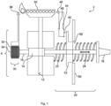
- a configuration of a gas cooktop 2 having a flame failure device 4 according to a first embodiment is discussed based on Fig. 1 .
- the gas cooktop has a valve device 10, a spring arrangement 20, a coil device 30, an ignition switch device 40, a burner 50, and a case 60.
- the burner 50 is fluidly connected to a gas passage 12 in the valve device 10.
- a piston 14 is movable within the valve device 10 between an open position and a closed position. If the piston 14 is in the open position, the piston 14 opens the gas passage 12 through the valve device, so that a combustion gas can flow through the gas passage 12 to the burner 50.
- Fig. 1 exemplarily depicts the piston 14 in the open position. If the piston 14 is located in the closed position, the piston 14 closes the gas passage 12 through the valve device 10, so that the combustion gas is blocked from flowing to the burner 50.
- the piston 14 may be a part of a shaft 16, and it is movable in the axial direction of the shaft 16 between the open position and the closed position. This movability is illustrated by a bold arrow in Fig. 1 .
- a handle 18 At one end of the shaft 16 there is a handle 18 affixed thereto. A user may move the shaft 16, including the piston 14, by gripping and moving the handle 18.
- the spring arrangement 20 is interposed between the handle 18 and a housing of the valve device fixed to the case 60. In an alternative, the spring arrangement 20 may be interposed between a section of the case 60 and the handle 18.
- the spring arrangement 20 acts like a compression spring.
- the spring arrangement 20 has two springs connected mechanically in series, which are a first spring 22 and a second spring 24.
- the first spring 22 has a lower spring coefficient than a spring coefficient of the second spring 24. That is, the first spring 22 preferably is compressible with less force compared to the second spring 24. In other words, in some embodiments, the first spring 22 may compress completely before the second spring 24 is completely compressed, when a user exerts axial pressure on the handle 18.
- the coil device 30 has a conductive coil 32, a plunger 34.
- a flame detection device 36 is connected to the coil 32 of the coil device 30.
- the flame detection device 36 preferably is a thermocouple, however there are preferred alternatives, such as an ionization detection device or an optical flame detection device.
- the flame detection device 36 is electrically connected to the conductive coil 32.
- the plunger 34 is affixed to the shaft 16.
- the plunger 34 is positioned at one distal end of the shaft 16.
- the coil 32 and the plunger 34 are arranged and/or configured such that the plunger 34 can dip into a hollow cylindrical space defined by the coil 32, when the piston 14 is in the open position.
- the plunger 34 is at least partly outside of the conductive coil 32, when the piston 14 is in the closed position.
- the flame detection device 36 When the flame detection device 36 detects a flame at the burner 50, it generates an electric current. The electric current is flowing through the conductive coil 32 to generate a magnetic field.
- the flame detection device 36, the conductive coil 32, the plunger 34, and the spring arrangement 20 are configured such that the magnetic flied can hold or arrest the plunger 34 while the spring arrangement 20 is compressed. That is, when a flame is burning, the magnetic field of the coil device 30 is opposed to a compression force of the spring arrangement 20. When a flame is burning, the magnetic force is stronger than the compression force of the spring arrangement 20.
- a plate 42 is mechanically interposed between the first spring 22 and the second spring 24.
- the plate 42 is configured to be slidable along the shaft 16 between an idle position and an activated position.
- the plate 42 may have a hat-shape that is guidable along a complete stroke of the plate by a corresponding opening 62 of the case 60, which is illustrated in Fig. 1 .
- the plate 42 is connected to a switch 44.
- the plate 42 and the switch 44 are one example for the ignition switch device 40.
- the switch 44 is configured to close an electric circuit comprising the switch 44, a power source 46, and an ignition device 48.
- the electric circuit may comprise the burner 50 as one conductor to/from the ignition device 48, and the power source 46 may be electrically interposed between the burner 50 and the switch 44.
- the first spring 22 is interposed between the plate 42 and the housing of the valve device 10.
- a stroke of the plate 42 is a compression stroke of the first spring 22.
- the stroke of the plate is an activation stroke of the switch 44.
- the compression stroke of the first spring 22 corresponds to the activation stroke of the ignition switch device 40.
- an amount of the compression stroke of the first spring 22 is not equal to an amount of the activation stroke of the ignition switch device.
- a lever is hinged at a section of the case 60 and is preferably also hinged at the plate 42 and/or the switch 44.
- the plate 42 and/or the hinged lever is arranged to compress a piezo-type ignition switch device.
- the first spring 22 is an elastic member of a piezo-type ignition switch device.
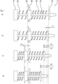
- stage a the burner 50 is off, the handle 18 is free from any external forces, the piston 14 is in the closed position, and the conductive coil 32 does not generate a magnetic field. Further, there is some slack present between the handle 18 and the second spring 24.
- the spring arrangement 20 When a user exerts additional pressure onto the handle, the spring arrangement 20 is compressed. Since the first spring device 22 is softer than the second spring device 24, the first spring 22 is more compressed than the second spring 24. This is depicted in stage c).
- the handle 18 and the piston 14 have travelled a distance L2, which is larger than the above distance L1.
- the handle 18 and the piston 14 have travelled a distance L3, and the plate 42 has travelled a distance L4.
- the distance L3 is larger than the distance L4.
- stage c the piston 14 is in the open position, although the gas passage 12 is not completely opened. That is, a small amount of gas is flowing through the gas passage 12 and from the burner 50.
- stage c the first spring device 22 is completely compressed. Since the first spring 22 is compressed by its compression stroke, the switch 44 is closed by its activation stroke, and electricity is supplied to the ignition device 48. Thus, the small flow of gas from the burner 50 gets easily ignited.
- stage d where the piston 14 is in the completely open position.
- the piston 14 and the handle 18 have travelled a distance L5, which is larger than distances L1 or L2.
- stage b) and d the handle 18 and the piston 14 have travelled a distance L6.
- stage d the second spring 24 is completely compressed.
- the distance L6 corresponds to a distance between the closed position and the completely open position of the piston 14 as well as a compression of the spring devices 22 and 24 together.
- the distance L1 may be 1 mm
- the distance L3 may be 1 mm
- the distance L4 may be 0.7 mm
- the distance L5 may be 4 mm.
- including the first spring device 22 into the spring arrangement 20 accounts to a saving of 0.7mm installation space.
Landscapes
- Engineering & Computer Science (AREA)
- Chemical & Material Sciences (AREA)
- Combustion & Propulsion (AREA)
- Mechanical Engineering (AREA)
- General Engineering & Computer Science (AREA)
- Control Of Combustion (AREA)
Abstract
Description
- The present invention relates to a flame failure device for a gas cooktop as well as a gas cooktop with such a flame failure device.
- Gas cooktops usually have a flame failure device (FFD), which may also be referred to as a flame supervision device (FSD). There are different kinds of flame failure devices, however this invention primarily concerns thermoelectric flame failure devices.
- A generic thermoelectric flame failure device may have a gas valve having a gas passage and a piston, that is arranged to open and close the gas passage. The piston is mechanically connected in series with a return spring and an arresting coil. The return spring is arranged and dimensioned to return the piston from an open position to a closed position. The arresting coil is electrically connected with a thermocouple, that generates an electric current while a corresponding flame is burning. The arresting coil is arranged and dimensioned to hold the piston against a force from the return spring in an open position as long as the thermocouple supplies the electric current to the arresting coil. In order to open the thermoelectric flame failure device, a user presses down a knob or the like, which moves the piston to the open position, and operates the return spring and the arresting coil accordingly. Then, the user has to ignite the flame. For example, the user may press the knob further down in order to actuate a piezo ignition device. Once the user has waited a predetermined period after igniting the flame, the coil arrests the piston. The user may then release the knob or the like. Once the flame breaks down, the thermocouple cools down, the electric current is not supplied any more, the arresting coils stop holding the piston, and the return spring closes the valve.
- Thus, there is a stack of a user interface, like the knob, a return spring, a piston, a coil, and an ignition device. However, a smaller construction is desired.
- It is one object of the present invention to provide a flame failure device that is reduced in size.
- Accordingly, a flame failure device for a gas cooktop is presented, having a valve device, a spring arrangement, a coil device, and an ignition switch device. The valve device has a piston and a gas passage. The piston is configured to open and close the gas passage. The spring arrangement is configured to return the piston from an open position, in which the gas passage is opened by the piston, to a closed position, in which the piston closes the gas passage. The spring arrangement has at least a first spring and a second spring. The first spring and the second spring are connected in series. The coil device is configured to hold and/or arrest the piston in the open position in a state when a predetermined electric current is flowing through the coil device. The ignition switch device is configured to emit an electric signal to an ignition device, when pressed by an activation stroke. The first spring is connected in parallel to the ignition switch device. A compression stroke of the first spring corresponds to and preferably is the activation stroke. The compression stroke of the first spring and a compression stroke of the second spring together are dimensioned to push the piston to close the gas passage.
- That is, the stroke to operate the ignition switch device is included into the stroke to open the gas passage. This is achieved by replacing the return spring by a series of two springs, wherein one of these springs is connected in parallel to the ignition switch device. Thus, the piston can be returned to the closed position by action of both the first and second springs together.
- The flame failure device according to the first embodiment thus saves the installation space for the ignition switch device stroke by the above series-parallel spring arrangement.
- A spring coefficient of the first spring may be smaller than a spring coefficient of the second spring. Thus, an operation of the ignition switch device can be ensured even if a user does not fully open the gas passage.
- In some embodiments, the spring arrangement may have a third spring connected in series with the first spring and the second spring. This feature provides additional user comfort, e.g. for compensating slack. For example, some jurisdictions may demand that there is a certain stroke of a user interface before the gas passage gets opened. In this case, a spring coefficient of the third spring preferably is smaller than the spring coefficients of the first spring and the second spring.
- A flame detection device may be electrically connected to the coil device. The flame detection device preferably is configured to then generate an electric current when it is detecting a flame. By providing the flame failure device with the flame detection device, the resulting system is easy to mount.
- Preferred flame detection devices are a thermocouple device, an ionization detection device, and an optical flame detection device.
- A thermocouple device may be connected to the coil device. The thermocouple device is configured to generate an electric current when it is exposed to a gas combustion. The electric current is dimensioned to cause the coil device to hold the piston in an open position. Thus, a thermoelectric flame failure device can be achieved, which is very reliably and durable.
- An ionization detection device may be connected to the coil device. The ionization detection device is configured to generate and/or switch an electric current when it is exposed to the ionizing field of a flame. The electric current is dimensioned to cause the coil device to hold the piston in an open position. Thus, an ionization flame failure device can be achieved, which is very reliable.
- An optical flame detection device may be connected to the coil device. The optical flame detection device is configured to generate and/or switch an electric current, when it detects an optical characteristic of a flame, like a color spectrum, an intensity, an infrared signature and/or a combination thereof. The electric current is dimensioned to cause the coil device to hold the piston in an open position. Thus, an optical flame failure device can be achieved, which also is very reliable.
- In short, it is proposed to provide a flame failure device for a gas cooktop, comprising: a valve device, having a gas passage and a piston for opening and closing the gas passage, a spring arrangement for returning the piston, having a first spring and a second spring connected in series, a coil device for holding the piston in an open position, when an electric current is flowing therethrough, and an ignition switch device configured to emit an electric signal to an ignition device when pressed by an activation stroke, wherein the first spring is connected in parallel to the ignition switch device, a compression stroke of the first spring corresponds to the activation stroke, and the compression stroke of the first spring and a compression stoke of the second spring together are dimensioned to push the piston to close the gas passage.
- The object of the invention is also solved by a gas cooktop having such a flame failure device and a burner. The burner is fluidly connected to the gas passage. The embodiments and features described with reference to the flame failure device of the present invention apply mutatis mutandis to the gas cooktop having the flame failure device.
- Further possible implementations or alternative solutions of the invention also encompass combinations - that are not explicitly mentioned herein - of features described above or below with regard to the embodiments. The person skilled in the art may also add individual or isolated aspects and features to the most basic form of the invention.
- Further embodiments, features and advantages of the present invention will become apparent from the subsequent description and dependent claims, taken in conjunction with the accompanying drawings, in which:
- Fig. 1
- schematically shows a system diagram of a gas cooktop having a flame failure device according to an embodiment of the invention; and
- Fig. 2
- schematically shows four operational stages of the flame failure device as shown in
Fig. 1 . - In the Figures, like reference numerals designate like or functionally equivalent elements, unless otherwise indicated.
- First, a configuration of a
gas cooktop 2 having aflame failure device 4 according to a first embodiment is discussed based onFig. 1 . - The gas cooktop has a
valve device 10, aspring arrangement 20, acoil device 30, anignition switch device 40, aburner 50, and acase 60. - The
burner 50 is fluidly connected to agas passage 12 in thevalve device 10. Apiston 14 is movable within thevalve device 10 between an open position and a closed position. If thepiston 14 is in the open position, thepiston 14 opens thegas passage 12 through the valve device, so that a combustion gas can flow through thegas passage 12 to theburner 50.Fig. 1 exemplarily depicts thepiston 14 in the open position. If thepiston 14 is located in the closed position, thepiston 14 closes thegas passage 12 through thevalve device 10, so that the combustion gas is blocked from flowing to theburner 50. - The
piston 14 may be a part of ashaft 16, and it is movable in the axial direction of theshaft 16 between the open position and the closed position. This movability is illustrated by a bold arrow inFig. 1 . - At one end of the
shaft 16 there is ahandle 18 affixed thereto. A user may move theshaft 16, including thepiston 14, by gripping and moving thehandle 18. - The
spring arrangement 20 is interposed between thehandle 18 and a housing of the valve device fixed to thecase 60. In an alternative, thespring arrangement 20 may be interposed between a section of thecase 60 and thehandle 18. - The
spring arrangement 20 acts like a compression spring. Thespring arrangement 20 has two springs connected mechanically in series, which are afirst spring 22 and asecond spring 24. Optionally, thefirst spring 22 has a lower spring coefficient than a spring coefficient of thesecond spring 24. That is, thefirst spring 22 preferably is compressible with less force compared to thesecond spring 24. In other words, in some embodiments, thefirst spring 22 may compress completely before thesecond spring 24 is completely compressed, when a user exerts axial pressure on thehandle 18. - The
coil device 30 has aconductive coil 32, aplunger 34. Aflame detection device 36 is connected to thecoil 32 of thecoil device 30. - The
flame detection device 36 preferably is a thermocouple, however there are preferred alternatives, such as an ionization detection device or an optical flame detection device. Theflame detection device 36 is electrically connected to theconductive coil 32. - The
plunger 34 is affixed to theshaft 16. Preferably, theplunger 34 is positioned at one distal end of theshaft 16. Thecoil 32 and theplunger 34 are arranged and/or configured such that theplunger 34 can dip into a hollow cylindrical space defined by thecoil 32, when thepiston 14 is in the open position. Preferably, theplunger 34 is at least partly outside of theconductive coil 32, when thepiston 14 is in the closed position. - When the
flame detection device 36 detects a flame at theburner 50, it generates an electric current. The electric current is flowing through theconductive coil 32 to generate a magnetic field. Theflame detection device 36, theconductive coil 32, theplunger 34, and thespring arrangement 20 are configured such that the magnetic flied can hold or arrest theplunger 34 while thespring arrangement 20 is compressed. That is, when a flame is burning, the magnetic field of thecoil device 30 is opposed to a compression force of thespring arrangement 20. When a flame is burning, the magnetic force is stronger than the compression force of thespring arrangement 20. - When the flame is extinguished, the electric current and the magnetic field weaken down towards zero, and the compression force from the
spring arrangement 20 is dimensioned and configured to return thepiston 14 to the closed position. - A
plate 42 is mechanically interposed between thefirst spring 22 and thesecond spring 24. Theplate 42 is configured to be slidable along theshaft 16 between an idle position and an activated position. - The
plate 42 may have a hat-shape that is guidable along a complete stroke of the plate by acorresponding opening 62 of thecase 60, which is illustrated inFig. 1 . - The
plate 42 is connected to aswitch 44. Theplate 42 and theswitch 44 are one example for theignition switch device 40. - The
switch 44 is configured to close an electric circuit comprising theswitch 44, apower source 46, and anignition device 48. In an alternative, the electric circuit may comprise theburner 50 as one conductor to/from theignition device 48, and thepower source 46 may be electrically interposed between theburner 50 and theswitch 44. When theplate 42 is in the idle position, theswitch 44 is open, and electricity is not supplied to theigniter 48. When theplate 42 is in the activated position, theswitch 44 is closed, and electricity is supplied to theignition device 48. - As the
plate 42 is interposed between thefirst spring 22 and thesecond spring 24, thefirst spring 22 is interposed between theplate 42 and the housing of thevalve device 10. Thus, when thespring device 20 gets compressed, a stroke of theplate 42 is a compression stroke of thefirst spring 22. The stroke of the plate is an activation stroke of theswitch 44. Thus, the compression stroke of thefirst spring 22 corresponds to the activation stroke of theignition switch device 40. - In an alternative, an amount of the compression stroke of the
first spring 22 is not equal to an amount of the activation stroke of the ignition switch device. In this case, preferably, a lever is hinged at a section of thecase 60 and is preferably also hinged at theplate 42 and/or theswitch 44. - In another alternative, the
plate 42 and/or the hinged lever is arranged to compress a piezo-type ignition switch device. - In yet another alternative, the
first spring 22 is an elastic member of a piezo-type ignition switch device. - An operation of the
flame failure device 4 is explained below with reference to Fig. 2 in four stages a) - d). - In stage a), the
burner 50 is off, thehandle 18 is free from any external forces, thepiston 14 is in the closed position, and theconductive coil 32 does not generate a magnetic field. Further, there is some slack present between thehandle 18 and thesecond spring 24. - When a user presses the
handle 18, thehandle 18 comes in contact with thesecond spring 24, thesecond spring 24 comes in contact with theplate 42, theplate 42 comes in contact with thefirst spring 22, and thefirst spring 22 comes in contact with the housing of thevalve device 10. This corresponds to stage b). Thehandle 18 and thepiston 14 have travelled a distance L1 between stages a) and b). In stage b), thepiston 14 still is in the closed position. - When a user exerts additional pressure onto the handle, the
spring arrangement 20 is compressed. Since thefirst spring device 22 is softer than thesecond spring device 24, thefirst spring 22 is more compressed than thesecond spring 24. This is depicted in stage c). - Between stages a) and c), the
handle 18 and thepiston 14 have travelled a distance L2, which is larger than the above distance L1. Between stages b) and c), thehandle 18 and thepiston 14 have travelled a distance L3, and theplate 42 has travelled a distance L4. As thesecond spring device 24 usually has an elastic behavior, the distance L3 is larger than the distance L4. - In stage c), the
piston 14 is in the open position, although thegas passage 12 is not completely opened. That is, a small amount of gas is flowing through thegas passage 12 and from theburner 50. - In stage c), the
first spring device 22 is completely compressed. Since thefirst spring 22 is compressed by its compression stroke, theswitch 44 is closed by its activation stroke, and electricity is supplied to theignition device 48. Thus, the small flow of gas from theburner 50 gets easily ignited. - Then, the user presses down the
handle 18 completely. This is stage d), where thepiston 14 is in the completely open position. Between stages a) and d), thepiston 14 and thehandle 18 have travelled a distance L5, which is larger than distances L1 or L2. Further, between stages b) and d), thehandle 18 and thepiston 14 have travelled a distance L6. In stage d), thesecond spring 24 is completely compressed. The distance L6 corresponds to a distance between the closed position and the completely open position of thepiston 14 as well as a compression of thespring devices - In a preferred embodiment, the distance L1 may be 1 mm, the distance L3 may be 1 mm, the distance L4 may be 0.7 mm, and the distance L5 may be 4 mm. In this case, including the
first spring device 22 into thespring arrangement 20 accounts to a saving of 0.7mm installation space. - Although the present invention has been described in accordance with preferred embodiments, it is obvious for the person skilled in the art that modifications are possible in all embodiments.
-
- 2
- gas cooktop
- 4
- flame failure device
- 10
- valve device
- 12
- gas passage
- 14
- piston
- 16
- shaft
- 18
- handle
- 20
- spring arrangement
- 22
- first spring
- 24
- second spring
- 30
- coil device
- 32
- conductive coil
- 34
- plunger
- 36
- flame detection device
- 40
- ignition switch device
- 42
- plate
- 44
- switch
- 46
- power source
- 48
- ignition device
- 42
- plate
- 50
- burner
- 60
- case
- 62
- opening
- a)
- stage
- b)
- stage
- c)
- stage
- d)
- stage
- L1
- distance, slack
- L2
- distance
- L3
- distance
- L4
- distance, compression stroke of first spring device
- L5
- distance
- L6
- distance, compression stroke of first and second spring devices
Claims (6)
- A flame failure device (4) for a gas cooktop (2), comprising:a valve device (10), having a gas passage (12) and a piston (14), wherein the piston (14) is configured to open and close the gas passage (12),a spring arrangement (20), that is configured to return the piston (14) from an open position to a closed position, having a first spring (22) and a second spring (24) connected in series,a coil device (30), that is configured to hold the piston (14) in the open position in a state, when an electric current is flowing through the coil device (30), andan ignition switch device (40), that is configured to emit an electric signal to an ignition device (48) when pressed by an activation stroke,wherein the first spring (22) is connected in parallel to the ignition switch device (40), and a compression stroke (L4) of the first spring (22) corresponds to the activation stroke, andwherein the compression stroke (L4) of the first spring and a compression stoke of the second spring (L6-L4) together are dimensioned to push the piston (14) to close the gas passage (12).
- The flame failure device (4) according to claim 1, wherein a spring coefficient of the first spring (22) is smaller than a spring coefficient of the second spring (24).
- The flame failure device (4) according to claim 1 or 2, wherein the spring arrangement (20) has a third spring connected in series with the first spring (22) and the second spring (24), wherein a spring coefficient of the third spring is smaller than the spring coefficients of the first spring (22) and the second spring (24).
- The flame failure device (4) according to any preceding claim, wherein a flame detection device (36) is electrically connected to the coil device (30), that is configured to generate an electric current when detecting a flame.
- The flame failure device (4) according to claim 4, wherein the flame detection device (36) is a thermocouple configured to generate an electric current when the thermocouple is exposed to a gas combustion.
- Gas cooktop (2) havinga flame failure device (4) according to any of the preceding claims, anda burner (50), that is fluidly connected to the gas passage (12).
Applications Claiming Priority (1)
| Application Number | Priority Date | Filing Date | Title |
|---|---|---|---|
| EP23382058 | 2023-01-24 |
Publications (2)
| Publication Number | Publication Date |
|---|---|
| EP4414606A1 true EP4414606A1 (en) | 2024-08-14 |
| EP4414606B1 EP4414606B1 (en) | 2025-12-03 |
Family
ID=85076062
Family Applications (1)
| Application Number | Title | Priority Date | Filing Date |
|---|---|---|---|
| EP24151000.7A Active EP4414606B1 (en) | 2023-01-24 | 2024-01-09 | Integrated flame failure device |
Country Status (1)
| Country | Link |
|---|---|
| EP (1) | EP4414606B1 (en) |
Citations (2)
| Publication number | Priority date | Publication date | Assignee | Title |
|---|---|---|---|---|
| DE68903585T2 (en) * | 1988-03-02 | 1993-05-19 | Gaz De France | GAS VALVE WITH A THERMOELECTRIC SECURITY SYSTEM AND DEVICE FOR USE OF SUCH A VALVE. |
| EP1750059A2 (en) * | 2005-08-05 | 2007-02-07 | BSH Bosch und Siemens Hausgeräte GmbH | Gas cooking hob |
-
2024
- 2024-01-09 EP EP24151000.7A patent/EP4414606B1/en active Active
Patent Citations (2)
| Publication number | Priority date | Publication date | Assignee | Title |
|---|---|---|---|---|
| DE68903585T2 (en) * | 1988-03-02 | 1993-05-19 | Gaz De France | GAS VALVE WITH A THERMOELECTRIC SECURITY SYSTEM AND DEVICE FOR USE OF SUCH A VALVE. |
| EP1750059A2 (en) * | 2005-08-05 | 2007-02-07 | BSH Bosch und Siemens Hausgeräte GmbH | Gas cooking hob |
Also Published As
| Publication number | Publication date |
|---|---|
| EP4414606B1 (en) | 2025-12-03 |
Similar Documents
| Publication | Publication Date | Title |
|---|---|---|
| CA2427366A1 (en) | Reset lockout and trip for circuit interrupting device | |
| US5233162A (en) | Electric cigar lighter with a bimetallic snap-action disc for overload protection | |
| KR20010031324A (en) | Gas regulating fixture | |
| CN104048328A (en) | Immediate ignition method of gas stove and device for realizing same | |
| EP4414606B1 (en) | Integrated flame failure device | |
| EP1909029A3 (en) | Safety electromagnetic valve with internal spring | |
| TW583055B (en) | Integrated spark and switch unit for combustion fastener driving tool | |
| US3811819A (en) | Modular gas lighter with electronic ignition | |
| US20030022120A1 (en) | Safety electronic lighter | |
| KR102194728B1 (en) | Ignition apparatus for gas range | |
| AU2003214138B2 (en) | Circuit breaker having fault-current cutoff | |
| US2850030A (en) | Safety valve devices | |
| US7690916B2 (en) | Method and apparatus for operating a gas-powered cooking and frying device | |
| US2297917A (en) | Automatic gas burner lighter | |
| EP0361474B1 (en) | Engine start facilitating valve | |
| US6682340B2 (en) | Lighter safety mechanism | |
| CA2515944C (en) | Process and circuit arrangement for igniting a gas stream | |
| ES2381115T3 (en) | Gas cooktop | |
| US4407255A (en) | Apparatus for supplying high voltage pulses | |
| US3195553A (en) | Burner control valve mechanism | |
| US3282325A (en) | Jackson etal burner control apparatus | |
| KR910000557Y1 (en) | Pressure-cooker | |
| JPS5952326B2 (en) | Gas appliance switching device | |
| WO2024170499A1 (en) | Control arrangement having a microswitch | |
| CN204063154U (en) | The gas-cooker that can immediately light a fire |
Legal Events
| Date | Code | Title | Description |
|---|---|---|---|
| PUAI | Public reference made under article 153(3) epc to a published international application that has entered the european phase |
Free format text: ORIGINAL CODE: 0009012 |
|
| STAA | Information on the status of an ep patent application or granted ep patent |
Free format text: STATUS: THE APPLICATION HAS BEEN PUBLISHED |
|
| AK | Designated contracting states |
Kind code of ref document: A1 Designated state(s): AL AT BE BG CH CY CZ DE DK EE ES FI FR GB GR HR HU IE IS IT LI LT LU LV MC ME MK MT NL NO PL PT RO RS SE SI SK SM TR |
|
| STAA | Information on the status of an ep patent application or granted ep patent |
Free format text: STATUS: REQUEST FOR EXAMINATION WAS MADE |
|
| 17P | Request for examination filed |
Effective date: 20250214 |
|
| GRAP | Despatch of communication of intention to grant a patent |
Free format text: ORIGINAL CODE: EPIDOSNIGR1 |
|
| STAA | Information on the status of an ep patent application or granted ep patent |
Free format text: STATUS: GRANT OF PATENT IS INTENDED |
|
| RIC1 | Information provided on ipc code assigned before grant |
Ipc: F23N 5/10 20060101AFI20250611BHEP Ipc: F23N 5/24 20060101ALI20250611BHEP Ipc: F24C 3/12 20060101ALI20250611BHEP |
|
| INTG | Intention to grant announced |
Effective date: 20250703 |
|
| GRAS | Grant fee paid |
Free format text: ORIGINAL CODE: EPIDOSNIGR3 |
|
| GRAA | (expected) grant |
Free format text: ORIGINAL CODE: 0009210 |
|
| STAA | Information on the status of an ep patent application or granted ep patent |
Free format text: STATUS: THE PATENT HAS BEEN GRANTED |
|
| AK | Designated contracting states |
Kind code of ref document: B1 Designated state(s): AL AT BE BG CH CY CZ DE DK EE ES FI FR GB GR HR HU IE IS IT LI LT LU LV MC ME MK MT NL NO PL PT RO RS SE SI SK SM TR |
|
| REG | Reference to a national code |
Ref country code: CH Ref legal event code: F10 Free format text: ST27 STATUS EVENT CODE: U-0-0-F10-F00 (AS PROVIDED BY THE NATIONAL OFFICE) Effective date: 20251203 Ref country code: GB Ref legal event code: FG4D |
|
| REG | Reference to a national code |
Ref country code: DE Ref legal event code: R096 Ref document number: 602024001432 Country of ref document: DE |
|
| REG | Reference to a national code |
Ref country code: IE Ref legal event code: FG4D |
|
| REG | Reference to a national code |
Ref country code: NL Ref legal event code: MP Effective date: 20251203 |
|
| PG25 | Lapsed in a contracting state [announced via postgrant information from national office to epo] |
Ref country code: ES Free format text: LAPSE BECAUSE OF FAILURE TO SUBMIT A TRANSLATION OF THE DESCRIPTION OR TO PAY THE FEE WITHIN THE PRESCRIBED TIME-LIMIT Effective date: 20251203 |
|
| REG | Reference to a national code |
Ref country code: LT Ref legal event code: MG9D |
|
| PG25 | Lapsed in a contracting state [announced via postgrant information from national office to epo] |
Ref country code: NO Free format text: LAPSE BECAUSE OF FAILURE TO SUBMIT A TRANSLATION OF THE DESCRIPTION OR TO PAY THE FEE WITHIN THE PRESCRIBED TIME-LIMIT Effective date: 20260303 |
|
| PG25 | Lapsed in a contracting state [announced via postgrant information from national office to epo] |
Ref country code: HR Free format text: LAPSE BECAUSE OF FAILURE TO SUBMIT A TRANSLATION OF THE DESCRIPTION OR TO PAY THE FEE WITHIN THE PRESCRIBED TIME-LIMIT Effective date: 20251203 Ref country code: FI Free format text: LAPSE BECAUSE OF FAILURE TO SUBMIT A TRANSLATION OF THE DESCRIPTION OR TO PAY THE FEE WITHIN THE PRESCRIBED TIME-LIMIT Effective date: 20251203 |
|
| PGFP | Annual fee paid to national office [announced via postgrant information from national office to epo] |
Ref country code: AT Payment date: 20260301 Year of fee payment: 3 |
|
| PGFP | Annual fee paid to national office [announced via postgrant information from national office to epo] |
Ref country code: IT Payment date: 20260131 Year of fee payment: 3 |
|
| PG25 | Lapsed in a contracting state [announced via postgrant information from national office to epo] |
Ref country code: RS Free format text: LAPSE BECAUSE OF FAILURE TO SUBMIT A TRANSLATION OF THE DESCRIPTION OR TO PAY THE FEE WITHIN THE PRESCRIBED TIME-LIMIT Effective date: 20260303 |
|
| PGFP | Annual fee paid to national office [announced via postgrant information from national office to epo] |
Ref country code: TR Payment date: 20260218 Year of fee payment: 3 |
|
| PG25 | Lapsed in a contracting state [announced via postgrant information from national office to epo] |
Ref country code: PL Free format text: LAPSE BECAUSE OF FAILURE TO SUBMIT A TRANSLATION OF THE DESCRIPTION OR TO PAY THE FEE WITHIN THE PRESCRIBED TIME-LIMIT Effective date: 20251203 |
|
| PG25 | Lapsed in a contracting state [announced via postgrant information from national office to epo] |
Ref country code: LV Free format text: LAPSE BECAUSE OF FAILURE TO SUBMIT A TRANSLATION OF THE DESCRIPTION OR TO PAY THE FEE WITHIN THE PRESCRIBED TIME-LIMIT Effective date: 20251203 |
|
| PG25 | Lapsed in a contracting state [announced via postgrant information from national office to epo] |
Ref country code: BG Free format text: LAPSE BECAUSE OF FAILURE TO SUBMIT A TRANSLATION OF THE DESCRIPTION OR TO PAY THE FEE WITHIN THE PRESCRIBED TIME-LIMIT Effective date: 20251203 |
|
| REG | Reference to a national code |
Ref country code: AT Ref legal event code: MK05 Ref document number: 1863962 Country of ref document: AT Kind code of ref document: T Effective date: 20251203 |
|
| PG25 | Lapsed in a contracting state [announced via postgrant information from national office to epo] |
Ref country code: NL Free format text: LAPSE BECAUSE OF FAILURE TO SUBMIT A TRANSLATION OF THE DESCRIPTION OR TO PAY THE FEE WITHIN THE PRESCRIBED TIME-LIMIT Effective date: 20251203 |
|
| PG25 | Lapsed in a contracting state [announced via postgrant information from national office to epo] |
Ref country code: LT Free format text: LAPSE BECAUSE OF FAILURE TO SUBMIT A TRANSLATION OF THE DESCRIPTION OR TO PAY THE FEE WITHIN THE PRESCRIBED TIME-LIMIT Effective date: 20251203 |
|
| PG25 | Lapsed in a contracting state [announced via postgrant information from national office to epo] |
Ref country code: SM Free format text: LAPSE BECAUSE OF FAILURE TO SUBMIT A TRANSLATION OF THE DESCRIPTION OR TO PAY THE FEE WITHIN THE PRESCRIBED TIME-LIMIT Effective date: 20251203 |
|
| PG25 | Lapsed in a contracting state [announced via postgrant information from national office to epo] |
Ref country code: AT Free format text: LAPSE BECAUSE OF FAILURE TO SUBMIT A TRANSLATION OF THE DESCRIPTION OR TO PAY THE FEE WITHIN THE PRESCRIBED TIME-LIMIT Effective date: 20251203 |
|
| PG25 | Lapsed in a contracting state [announced via postgrant information from national office to epo] |
Ref country code: EE Free format text: LAPSE BECAUSE OF FAILURE TO SUBMIT A TRANSLATION OF THE DESCRIPTION OR TO PAY THE FEE WITHIN THE PRESCRIBED TIME-LIMIT Effective date: 20251203 |
|
| PG25 | Lapsed in a contracting state [announced via postgrant information from national office to epo] |
Ref country code: PT Free format text: LAPSE BECAUSE OF FAILURE TO SUBMIT A TRANSLATION OF THE DESCRIPTION OR TO PAY THE FEE WITHIN THE PRESCRIBED TIME-LIMIT Effective date: 20260406 Ref country code: IS Free format text: LAPSE BECAUSE OF FAILURE TO SUBMIT A TRANSLATION OF THE DESCRIPTION OR TO PAY THE FEE WITHIN THE PRESCRIBED TIME-LIMIT Effective date: 20260403 |
|
| PG25 | Lapsed in a contracting state [announced via postgrant information from national office to epo] |
Ref country code: CZ Free format text: LAPSE BECAUSE OF FAILURE TO SUBMIT A TRANSLATION OF THE DESCRIPTION OR TO PAY THE FEE WITHIN THE PRESCRIBED TIME-LIMIT Effective date: 20251203 |
|
| PG25 | Lapsed in a contracting state [announced via postgrant information from national office to epo] |
Ref country code: SK Free format text: LAPSE BECAUSE OF FAILURE TO SUBMIT A TRANSLATION OF THE DESCRIPTION OR TO PAY THE FEE WITHIN THE PRESCRIBED TIME-LIMIT Effective date: 20251203 |
|
| PG25 | Lapsed in a contracting state [announced via postgrant information from national office to epo] |
Ref country code: SE Free format text: LAPSE BECAUSE OF FAILURE TO SUBMIT A TRANSLATION OF THE DESCRIPTION OR TO PAY THE FEE WITHIN THE PRESCRIBED TIME-LIMIT Effective date: 20251203 |