EP4414592A1 - Assembly of metal flange and resin tube, and method for manufacturing said assembly - Google Patents
Assembly of metal flange and resin tube, and method for manufacturing said assembly Download PDFInfo
- Publication number
- EP4414592A1 EP4414592A1 EP22878151.4A EP22878151A EP4414592A1 EP 4414592 A1 EP4414592 A1 EP 4414592A1 EP 22878151 A EP22878151 A EP 22878151A EP 4414592 A1 EP4414592 A1 EP 4414592A1
- Authority
- EP
- European Patent Office
- Prior art keywords
- resin pipe
- metal flange
- rib
- assembly
- resin
- Prior art date
- Legal status (The legal status is an assumption and is not a legal conclusion. Google has not performed a legal analysis and makes no representation as to the accuracy of the status listed.)
- Pending
Links
Images




Classifications
-
- F—MECHANICAL ENGINEERING; LIGHTING; HEATING; WEAPONS; BLASTING
- F16—ENGINEERING ELEMENTS AND UNITS; GENERAL MEASURES FOR PRODUCING AND MAINTAINING EFFECTIVE FUNCTIONING OF MACHINES OR INSTALLATIONS; THERMAL INSULATION IN GENERAL
- F16L—PIPES; JOINTS OR FITTINGS FOR PIPES; SUPPORTS FOR PIPES, CABLES OR PROTECTIVE TUBING; MEANS FOR THERMAL INSULATION IN GENERAL
- F16L23/00—Flanged joints
- F16L23/02—Flanged joints the flanges being connected by members tensioned axially
- F16L23/024—Flanged joints the flanges being connected by members tensioned axially characterised by how the flanges are joined to, or form an extension of, the pipes
-
- F—MECHANICAL ENGINEERING; LIGHTING; HEATING; WEAPONS; BLASTING
- F16—ENGINEERING ELEMENTS AND UNITS; GENERAL MEASURES FOR PRODUCING AND MAINTAINING EFFECTIVE FUNCTIONING OF MACHINES OR INSTALLATIONS; THERMAL INSULATION IN GENERAL
- F16L—PIPES; JOINTS OR FITTINGS FOR PIPES; SUPPORTS FOR PIPES, CABLES OR PROTECTIVE TUBING; MEANS FOR THERMAL INSULATION IN GENERAL
- F16L23/00—Flanged joints
- F16L23/02—Flanged joints the flanges being connected by members tensioned axially
- F16L23/024—Flanged joints the flanges being connected by members tensioned axially characterised by how the flanges are joined to, or form an extension of, the pipes
- F16L23/028—Flanged joints the flanges being connected by members tensioned axially characterised by how the flanges are joined to, or form an extension of, the pipes the flanges being held against a shoulder
- F16L23/0283—Flanged joints the flanges being connected by members tensioned axially characterised by how the flanges are joined to, or form an extension of, the pipes the flanges being held against a shoulder the collar being integral with the pipe
-
- B—PERFORMING OPERATIONS; TRANSPORTING
- B29—WORKING OF PLASTICS; WORKING OF SUBSTANCES IN A PLASTIC STATE IN GENERAL
- B29C—SHAPING OR JOINING OF PLASTICS; SHAPING OF MATERIAL IN A PLASTIC STATE, NOT OTHERWISE PROVIDED FOR; AFTER-TREATMENT OF THE SHAPED PRODUCTS, e.g. REPAIRING
- B29C45/00—Injection moulding, i.e. forcing the required volume of moulding material through a nozzle into a closed mould; Apparatus therefor
- B29C45/14—Injection moulding, i.e. forcing the required volume of moulding material through a nozzle into a closed mould; Apparatus therefor incorporating preformed parts or layers, e.g. injection moulding around inserts or for coating articles
- B29C45/14311—Injection moulding, i.e. forcing the required volume of moulding material through a nozzle into a closed mould; Apparatus therefor incorporating preformed parts or layers, e.g. injection moulding around inserts or for coating articles using means for bonding the coating to the articles
-
- B—PERFORMING OPERATIONS; TRANSPORTING
- B29—WORKING OF PLASTICS; WORKING OF SUBSTANCES IN A PLASTIC STATE IN GENERAL
- B29C—SHAPING OR JOINING OF PLASTICS; SHAPING OF MATERIAL IN A PLASTIC STATE, NOT OTHERWISE PROVIDED FOR; AFTER-TREATMENT OF THE SHAPED PRODUCTS, e.g. REPAIRING
- B29C45/00—Injection moulding, i.e. forcing the required volume of moulding material through a nozzle into a closed mould; Apparatus therefor
- B29C45/14—Injection moulding, i.e. forcing the required volume of moulding material through a nozzle into a closed mould; Apparatus therefor incorporating preformed parts or layers, e.g. injection moulding around inserts or for coating articles
- B29C45/14598—Coating tubular articles
- B29C45/14622—Lining the inner or outer surface of tubular articles
-
- B—PERFORMING OPERATIONS; TRANSPORTING
- B29—WORKING OF PLASTICS; WORKING OF SUBSTANCES IN A PLASTIC STATE IN GENERAL
- B29C—SHAPING OR JOINING OF PLASTICS; SHAPING OF MATERIAL IN A PLASTIC STATE, NOT OTHERWISE PROVIDED FOR; AFTER-TREATMENT OF THE SHAPED PRODUCTS, e.g. REPAIRING
- B29C45/00—Injection moulding, i.e. forcing the required volume of moulding material through a nozzle into a closed mould; Apparatus therefor
- B29C45/17—Component parts, details or accessories; Auxiliary operations
- B29C45/1703—Introducing an auxiliary fluid into the mould
- B29C45/1704—Introducing an auxiliary fluid into the mould the fluid being introduced into the interior of the injected material which is still in a molten state, e.g. for producing hollow articles
-
- B—PERFORMING OPERATIONS; TRANSPORTING
- B29—WORKING OF PLASTICS; WORKING OF SUBSTANCES IN A PLASTIC STATE IN GENERAL
- B29C—SHAPING OR JOINING OF PLASTICS; SHAPING OF MATERIAL IN A PLASTIC STATE, NOT OTHERWISE PROVIDED FOR; AFTER-TREATMENT OF THE SHAPED PRODUCTS, e.g. REPAIRING
- B29C49/00—Blow-moulding, i.e. blowing a preform or parison to a desired shape within a mould; Apparatus therefor
- B29C49/02—Combined blow-moulding and manufacture of the preform or the parison
- B29C49/06—Injection blow-moulding
-
- B—PERFORMING OPERATIONS; TRANSPORTING
- B29—WORKING OF PLASTICS; WORKING OF SUBSTANCES IN A PLASTIC STATE IN GENERAL
- B29C—SHAPING OR JOINING OF PLASTICS; SHAPING OF MATERIAL IN A PLASTIC STATE, NOT OTHERWISE PROVIDED FOR; AFTER-TREATMENT OF THE SHAPED PRODUCTS, e.g. REPAIRING
- B29C49/00—Blow-moulding, i.e. blowing a preform or parison to a desired shape within a mould; Apparatus therefor
- B29C49/20—Blow-moulding, i.e. blowing a preform or parison to a desired shape within a mould; Apparatus therefor of articles having inserts or reinforcements ; Handling of inserts or reinforcements
-
- F—MECHANICAL ENGINEERING; LIGHTING; HEATING; WEAPONS; BLASTING
- F16—ENGINEERING ELEMENTS AND UNITS; GENERAL MEASURES FOR PRODUCING AND MAINTAINING EFFECTIVE FUNCTIONING OF MACHINES OR INSTALLATIONS; THERMAL INSULATION IN GENERAL
- F16L—PIPES; JOINTS OR FITTINGS FOR PIPES; SUPPORTS FOR PIPES, CABLES OR PROTECTIVE TUBING; MEANS FOR THERMAL INSULATION IN GENERAL
- F16L23/00—Flanged joints
- F16L23/12—Flanged joints specially adapted for particular pipes
-
- B—PERFORMING OPERATIONS; TRANSPORTING
- B29—WORKING OF PLASTICS; WORKING OF SUBSTANCES IN A PLASTIC STATE IN GENERAL
- B29C—SHAPING OR JOINING OF PLASTICS; SHAPING OF MATERIAL IN A PLASTIC STATE, NOT OTHERWISE PROVIDED FOR; AFTER-TREATMENT OF THE SHAPED PRODUCTS, e.g. REPAIRING
- B29C45/00—Injection moulding, i.e. forcing the required volume of moulding material through a nozzle into a closed mould; Apparatus therefor
- B29C45/14—Injection moulding, i.e. forcing the required volume of moulding material through a nozzle into a closed mould; Apparatus therefor incorporating preformed parts or layers, e.g. injection moulding around inserts or for coating articles
- B29C2045/1486—Details, accessories and auxiliary operations
- B29C2045/14868—Pretreatment of the insert, e.g. etching, cleaning
-
- B—PERFORMING OPERATIONS; TRANSPORTING
- B29—WORKING OF PLASTICS; WORKING OF SUBSTANCES IN A PLASTIC STATE IN GENERAL
- B29C—SHAPING OR JOINING OF PLASTICS; SHAPING OF MATERIAL IN A PLASTIC STATE, NOT OTHERWISE PROVIDED FOR; AFTER-TREATMENT OF THE SHAPED PRODUCTS, e.g. REPAIRING
- B29C45/00—Injection moulding, i.e. forcing the required volume of moulding material through a nozzle into a closed mould; Apparatus therefor
- B29C45/17—Component parts, details or accessories; Auxiliary operations
- B29C45/1703—Introducing an auxiliary fluid into the mould
- B29C45/1704—Introducing an auxiliary fluid into the mould the fluid being introduced into the interior of the injected material which is still in a molten state, e.g. for producing hollow articles
- B29C2045/1719—Introducing an auxiliary fluid into the mould the fluid being introduced into the interior of the injected material which is still in a molten state, e.g. for producing hollow articles making tubular articles
-
- B—PERFORMING OPERATIONS; TRANSPORTING
- B29—WORKING OF PLASTICS; WORKING OF SUBSTANCES IN A PLASTIC STATE IN GENERAL
- B29C—SHAPING OR JOINING OF PLASTICS; SHAPING OF MATERIAL IN A PLASTIC STATE, NOT OTHERWISE PROVIDED FOR; AFTER-TREATMENT OF THE SHAPED PRODUCTS, e.g. REPAIRING
- B29C45/00—Injection moulding, i.e. forcing the required volume of moulding material through a nozzle into a closed mould; Apparatus therefor
- B29C45/17—Component parts, details or accessories; Auxiliary operations
- B29C45/1703—Introducing an auxiliary fluid into the mould
- B29C45/1704—Introducing an auxiliary fluid into the mould the fluid being introduced into the interior of the injected material which is still in a molten state, e.g. for producing hollow articles
- B29C2045/1722—Introducing an auxiliary fluid into the mould the fluid being introduced into the interior of the injected material which is still in a molten state, e.g. for producing hollow articles injecting fluids containing plastic material
-
- B—PERFORMING OPERATIONS; TRANSPORTING
- B29—WORKING OF PLASTICS; WORKING OF SUBSTANCES IN A PLASTIC STATE IN GENERAL
- B29C—SHAPING OR JOINING OF PLASTICS; SHAPING OF MATERIAL IN A PLASTIC STATE, NOT OTHERWISE PROVIDED FOR; AFTER-TREATMENT OF THE SHAPED PRODUCTS, e.g. REPAIRING
- B29C49/00—Blow-moulding, i.e. blowing a preform or parison to a desired shape within a mould; Apparatus therefor
- B29C49/20—Blow-moulding, i.e. blowing a preform or parison to a desired shape within a mould; Apparatus therefor of articles having inserts or reinforcements ; Handling of inserts or reinforcements
- B29C2049/2017—Blow-moulding, i.e. blowing a preform or parison to a desired shape within a mould; Apparatus therefor of articles having inserts or reinforcements ; Handling of inserts or reinforcements outside the article
-
- B—PERFORMING OPERATIONS; TRANSPORTING
- B29—WORKING OF PLASTICS; WORKING OF SUBSTANCES IN A PLASTIC STATE IN GENERAL
- B29K—INDEXING SCHEME ASSOCIATED WITH SUBCLASSES B29B, B29C OR B29D, RELATING TO MOULDING MATERIALS OR TO MATERIALS FOR MOULDS, REINFORCEMENTS, FILLERS OR PREFORMED PARTS, e.g. INSERTS
- B29K2705/00—Use of metals, their alloys or their compounds, for preformed parts, e.g. for inserts
-
- B—PERFORMING OPERATIONS; TRANSPORTING
- B29—WORKING OF PLASTICS; WORKING OF SUBSTANCES IN A PLASTIC STATE IN GENERAL
- B29L—INDEXING SCHEME ASSOCIATED WITH SUBCLASS B29C, RELATING TO PARTICULAR ARTICLES
- B29L2023/00—Tubular articles
-
- B—PERFORMING OPERATIONS; TRANSPORTING
- B29—WORKING OF PLASTICS; WORKING OF SUBSTANCES IN A PLASTIC STATE IN GENERAL
- B29L—INDEXING SCHEME ASSOCIATED WITH SUBCLASS B29C, RELATING TO PARTICULAR ARTICLES
- B29L2023/00—Tubular articles
- B29L2023/22—Tubes or pipes, i.e. rigid
-
- B—PERFORMING OPERATIONS; TRANSPORTING
- B29—WORKING OF PLASTICS; WORKING OF SUBSTANCES IN A PLASTIC STATE IN GENERAL
- B29L—INDEXING SCHEME ASSOCIATED WITH SUBCLASS B29C, RELATING TO PARTICULAR ARTICLES
- B29L2031/00—Other particular articles
- B29L2031/24—Pipe joints or couplings
Definitions
- the present invention relates to an assembly of a metal flange and a resin pipe and a method of manufacturing the assembly, and particularly relates to an assembly that allows for fixing the metal flange to the resin pipe at a predetermined position without displacement and providing improved durability of the resin pipe at a fixed portion of both and a method of manufacturing the assembly.
- Resin pipes which are lighter than metal pipes, have been used for various applications.
- the resin pipe is attached to a target device or the like via an externally fitted flange (see, for example, Patent Document 1).
- the flange may be made of resin to reduce the weight, the use of a metal flange is necessary to ensure sufficient durability under use conditions in which a comparatively large load continuously acts.
- Patent Document 1 JP 7-80922 A
- An object of the present invention is to provide an assembly of a metal flange and a resin pipe that allows for fixing the metal flange to the resin pipe at a predetermined position without displacement and providing improved durability of the resin pipe at a fixed portion of both and a method of manufacturing the assembly.
- the metal flange may be externally fitted to and integrated with the resin pipe.
- the metal flange may be fitted in a fixing groove continuous over an entire circumference of an outer circumferential surface of the resin pipe in a circumferential direction. Unevenness may be formed on a surface of an insertion hole of the metal flange into which the resin pipe is inserted. An outer circumferential surface of the fixing groove may enter the unevenness.
- a circumferential rib may be formed on at least one side of both ends of the metal flange in a longitudinal direction of the resin pipe, abut on an end surface of the metal flange, have a diameter larger than an outer diameter of the resin pipe, and be continuous over the entire circumference of the outer circumferential surface of the resin pipe in the circumferential direction.
- the metal flange may be externally fitted to and integrated with the resin pipe.
- the method may include: forming unevenness on a surface of an insertion hole of the metal flange into which the resin pipe is inserted; disposing the metal flange in an insert portion provided in a cavity body of a mold for forming the resin pipe; forming a rib forming cavity on at least one side of both ends of the insert portion in an extension direction of the cavity body, the rib forming cavity being connected to the insert portion, having a diameter larger than an outer diameter of the cavity body, and being continuous over an entire circumference of an outer circumferential surface of the cavity body in a circumferential direction; injecting molten resin into the cavity body and the rib forming cavity in a state where the mold is clamped to form the resin pipe by curing the molten resin; fitting the metal flange into a fixing groove continuous over the entire circumference of the outer circum
- a structure in which the metal flange is fitted into the fixing groove continuous over the entire circumference of the outer circumferential surface of the resin pipe in the circumferential direction and the outer circumferential surface of the fixing groove enters the unevenness on the surface of the insertion hole of the metal flange is employed, which is advantageous for fixing the metal flange to the resin pipe at a predetermined position without displacement.
- a structure in which the circumferential rib is provided on at least one side of both ends of the metal flange in the longitudinal direction of the resin pipe, abuts on the end surface of the metal flange, has a diameter larger than the outer diameter of the resin pipe, and is continuous over the entire circumference of the outer circumferential surface of the resin pipe in the circumferential direction is employed. Accordingly, stress generated on the resin pipe at a fixed portion of both is reduced by the circumferential rib. As a result, it is advantageous to improve the durability of the resin pipe at the fixed portion of both.
- an embodiment of an assembly 1 manufactured by the embodiment of the present invention is formed by externally fitting a metal flange 2 to a resin pipe 5 such that both are integrated.
- the resin pipe 5 is a straight pipe having an outer diameter do and an inner diameter di, but there may be a case where the resin pipe 5 is a bent pipe.
- the outer diameter do is, for example, about 6 mm or more and 150 mm or less
- the inner diameter di is, for example, about 4 mm or more and 146 mm or less.
- Both end portions of the resin pipe 5 in a longitudinal direction are connected to various devices, joint parts, and the like.
- the other longitudinal end portion of the resin pipe 5 is an insertion portion 8 inserted into a flow path 11a of a target device 11.
- a seal member 8d disposed in the insertion portion 8 abuts on an inner circumferential surface of the flow path 11a to ensure a sealing property between the resin pipe 5 and the flow path 11a.
- One end surface of the metal flange 2 abuts on an opposed surface of the target device 11, and a fixing bolt 10 passing through a mounting hole 4 of the metal flange 2 is screwed into a bolt hole of the target device 11.
- a joint product 1 is connected and fixed to the target device 11.
- the metal flange 2 includes an insertion hole 3 into which the resin pipe 5 is inserted and the mounting hole 4.
- various metals can be used as the material of the metal flange 2, aluminum or an aluminum alloy is preferable for weight reduction.
- a thickness t of the metal flange 2 is, for example, about 70% or more and 100% or less of the outer diameter do of the resin pipe 5.
- the surface of the insertion hole 3 includes a large number of projections 3a and is unevenly formed.
- each of the projections 3a extends linearly in parallel with the longitudinal direction of the resin pipe 5.
- the respective projections 3a are preferably disposed at regular intervals in a circumferential direction.
- the number of the projections 3a and a projection amount of the projection 3a in a radial direction of the insertion hole 3 are determined as appropriate.
- the number of the projections 3a is about 8 pieces or more and 32 pieces or less, and the projection amount is about several mm.
- the respective projections 3a are inclined with respect to the longitudinal direction of the resin pipe 5 to extend spirally.
- the projections 3a extending in the circumferential direction of the insertion hole 3 can be provided.
- at least one projection 3a (the projection 3a not parallel to the circumferential direction of the resin pipe 5) extending in the longitudinal direction of the resin pipe 5 only needs to be provided on the surface of the insertion hole 3.
- the resin pipe 5 includes a pipe passage 6 passing through and extending in the longitudinal direction.
- various known resins such as nylon resin (66 nylon or the like), polypropylene, and ABS resin, are used.
- the type (specification) of the resin used for the resin pipe 5 is determined based on performance required for the resin pipe 5. For example, resin having excellent durability against a fluid flowing through the pipe passage 6 and durability against external impact, wear, ultraviolet rays, and the like is used.
- short fiber for example, glass fiber or carbon fiber
- the size of the short fibers is, for example, about 0.001 mm or more and 1.0 mm or less in an outer diameter and about 0.01 mm or more and 10 mm or less in a length.
- enlarged-diameter portions 8b and 8c continuous over the entire circumference of the outer circumferential surface of the resin pipe 5 in the circumferential direction are disposed to be separated in the longitudinal direction of the resin pipe 5.
- a portion between the respective enlarged-diameter portions 8b and 8c is a seal groove 8a continuous over the entire circumference of the outer circumferential surface of the resin pipe 5 in the circumferential direction.
- the seal member 8d such as an O-ring, made of rubber or elastomer is fitted into the seal groove 8a.
- a groove bottom of the seal groove 8a can be located on the inner circumferential side of the outer diameter do
- the groove bottom is preferably located at a position same as the outer diameter do or on the outer circumferential side of the outer diameter do to ensure a thickness of a circumferential wall of the resin pipe 5.
- the outer circumferential surfaces of the respective enlarged-diameter portions 8b and 8c are located on the position equivalent to the outer diameter do in some cases.
- the outer circumferential surfaces of the respective enlarged-diameter portions 8b and 8c are located on the outer circumferential side of the outer diameter do.
- the resin pipe 5 includes a fixing groove 7 on the outer circumferential surface continuous over the entire circumference in the circumferential direction.
- the metal flange 2 is fitted to the fixing groove 7.
- the groove bottom of the fixing groove 7 can be located on the inner circumferential side of the outer diameter do, but is preferably located at the position same as the outer diameter do or on the outer circumferential side of the outer diameter do to ensure the thickness of the circumferential wall of the resin pipe 5.
- the outer circumferential surface of the fixing groove 7 enters the unevenness formed on the surface of the insertion hole 3.
- a circumferential rib 9a is provided at a position separated from one enlarged-diameter portion 8c in the longitudinal direction of the resin pipe 5.
- the circumferential rib 9a is continuous over the entire circumference of the outer circumferential surface of the resin pipe 5 in the circumferential direction.
- the fixing groove 7 is formed between one enlarged-diameter portion 8c and the circumferential rib 9a.
- annular circumferential rib 9a projecting toward the outer circumferential side from the outer diameter do of the resin pipe 5.
- the circumferential rib 9a abuts on the surface of one end surface of the metal flange 2 over the entire circumference in the circumferential direction.
- An effective length L (a minimum length with respect to the longitudinal direction of the resin pipe 5) of the circumferential rib 9a is preferably 2 mm or more, and is about 2 mm or more and 20 mm or less.
- a projection amount h of the circumferential rib 9a is preferably 2.0 mm or more and, for example, about 2.0 mm or more and 10.0 mm or less.
- the enlarged-diameter portion 8c is provided on the other side of both ends of the metal flange 2 in the longitudinal direction of the resin pipe 5.
- the enlarged-diameter portion 8c projects toward the outer circumferential side from the outer diameter do of the resin pipe 5, abuts on the surface of the other end surface of the metal flange 2, and is continuous over the entire circumference of the outer circumferential surface of the resin pipe 5 in the circumferential direction. Therefore, the enlarged-diameter portion 8c also functions as the circumferential rib 9a.
- the projection amount of the enlarged-diameter portion 8c from the outer circumferential surface of the outer diameter do toward the outer circumferential side is small and smaller than the projection amount h.
- the circumferential rib 9a only needs to be disposed on at least one side of both ends of the metal flange 2 in the longitudinal direction of the resin pipe 5, and a structure having the circumferential rib 9a only on one side can be employed.
- a longitudinal rib 9b connected to the circumferential rib 9a and extending to one side in the longitudinal direction of the resin pipe 5 is provided in addition to the circumferential rib 9a can be employed.
- At least the three longitudinal ribs 9b are disposed to be separated at regular intervals in the circumferential direction of the resin pipe 5.
- the 4 or more and 12 or less longitudinal ribs 9b are disposed at regular intervals in the circumferential direction.
- the respective longitudinal ribs 9b are set to have substantially the same specifications.
- a length L1 of the longitudinal rib 9b is, for example, about 2.0 mm or more and 50.0 mm or less.
- the projection amount h of the longitudinal rib 9b from the outer diameter do is preferably 2 mm or more and may be equal to or less than the projection amount h of the circumferential rib 9a.
- a width W of the longitudinal rib 9b is, for example, about 2.0 mm or more and 30.0 mm or less.
- the lateral cross-sectional shape of the longitudinal rib 9b is not limited to the quadrangular shape as exemplified in FIG. 9 , but any polygonal shape including a semi-circular shape, a triangular shape, and the like can be employed.
- the longitudinal rib 9b having a lateral cross-sectional shape with no corner portion is advantageous to provide the improved durability of the longitudinal rib 9b.
- the longitudinal rib 9b has a substantially triangular shape inclined from the outer edge of the circumferential rib 9a toward the outer circumferential surface of the resin pipe 5 in a longitudinal cross-sectional view.
- the longitudinal rib 9b can have another shape, such as a quadrangular shape.
- the longitudinal rib 9b having a substantially triangular shape in a longitudinal cross-sectional view is preferably employed.
- the forming device 14 includes a cylinder 14a that injects molten resin R into a mold 12 (cavity 13) and an assist gas injection unit 14b that injects an assist gas G into the mold 12 (cavity 13).
- the mold 12 is constituted of one mold 12a and the other mold 12b assembled to one another.
- the mutual molds 12a and 12b are bonded and separated with a parting line PL as a boundary.
- the mold 12 is not limited to such a two split type, and various known types can be used.
- the cavity 13 which is a hollow, is formed, and a discharge portion of the assist gas G injected into the cavity 13 is also formed.
- a cavity body 13a for forming the resin pipe 5 a cavity body 13a for forming the resin pipe 5
- a rib forming cavity 13b for forming the circumferential rib 9a and the longitudinal rib 9b
- an insert portion 13c for disposing the metal flange 2 are formed.
- the rib forming cavity 13b is formed to be connected to the insert portion 13c, has a diameter larger than the outer diameter of the cavity body 13a, and is continuous over the entire circumference of the outer circumferential surface of the cavity body 13a in the circumferential direction.
- the molten rein R filled in the rib forming cavity 13b is cured to form the circumferential rib 9a and the longitudinal rib 9b. Therefore, when the circumferential ribs 9a are formed on the respective sides of both end surfaces of the metal flange 2, the rib forming cavities 13b are formed on the respective sides at both ends of the insert portion 13c in the extension direction of the cavity body 13a. When the circumferential rib 9a is formed only on one side of both end surfaces of the metal flange 2, the rib forming cavity 13b is formed on only one side of the insert portion 13c in the extension direction of the cavity body 13a.
- the projections 3a are provided on the surface of the insertion hole 3 of the metal flange 2 to form the surface unevenly.
- the projections 3a may be provided by machining or manual work.
- the mutual molds 12a and 12b are assembled to clamp the mold 12. Then, the molten resin R is injected from the cylinder 14a to fill the cavity 13 (the cavity body 13a and the rib forming cavity 13b) with the molten resin R as exemplified in FIG. 13 .
- the assist gas G such as nitrogen gas
- the assist gas G is injected at a predetermined high pressure into the cavity body 13a filled with the molten resin R and is caused to pass through in the extension direction of the cavity body 13a.
- the assist gas G passing through the cavity body 13a excess molten resin is discharged from the cavity body 13a to form the pipe passage 6.
- the metal flange 2 is fitted to the fixing groove 7 continuous over the entire circumference of the outer circumferential surface of the resin pipe 5 in the circumferential direction, and the outer circumferential surface of the fixing groove 7 is caused to enter the unevenness on the surface of the insertion hole 3.
- the circumferential rib 9a and the longitudinal rib 9b described above are formed on at least one side of both ends of the metal flange 2 in the longitudinal direction of the resin pipe 5.
- the forming method using the assist gas G as an assist material is employed in the embodiment, but an appropriate material of other gases, liquid, such as water, and a solid, such as a metal ball and a resin ball, can be used as the assist material.
- the known appropriate mechanism is employed as the assist gas injection unit 14b according to the type of the assist material.
- various known forming methods that do not use an assist material can be employed. For example, in a state in which a core extending in the longitudinal direction of the cavity body is disposed on the cavity body 13a, the molten resin R is injected into the cavity 13, and then the core is removed to allow for forming the pipe passage 6 and forming the resin pipe 5.
- a forming method using an assist material is preferably employed. This is because a bent portion of the resin pipe 5 is easily formed by the forming method using the assist material.
- a dashed line PL exemplified in FIG. 15 serves as a parting line of the mold 12
- the dashed line PL exemplified in FIG. 16 serves as a parting line of the mold 12.
- the assembly 1 of the embodiment of the present invention has a structure in which the metal flange 2 is fitted into the fixing groove 7 continuous over the entire circumference of the outer circumferential surface of the resin pipe 5 in the circumferential direction, and the outer circumferential surface of the fixing groove 7 enters the unevenness on the surface of the insertion hole 3. Therefore, it is advantageous to fix the metal flange 2 to the resin pipe 5 at a predetermined position without displacement.
- the projections 3a provided on the surface of the insertion hole 3 prevent the metal flange 2 from rotating around the resin pipe 5, and also prevent the metal flange 2 from being displaced in the longitudinal direction of the resin pipe 5. Therefore, by providing the projections 3a, it is possible to reduce a burden on the circumferential rib 9a and the enlarged-diameter portion 8c that prevent the metal flange 2 from being displaced in the longitudinal direction of the resin pipe 5.
- a service life of the resin pipe 5 tends to be further short under the condition that a used internal pressure of the resin pipe 5 of 30 MPa or more, but the service life can be extended by applying the embodiment of the present invention.
- the resin pipe 5 having the used internal pressure of 3.5 MPa or more (or 30 MPa or more) a pipe through which a refrigerant of an air conditioner mounted on an automobile flows can be exemplified.
- the specification of including the above-described longitudinal rib 9b in addition to the circumferential rib 9a is advantageous in further improving the durability of the resin pipe 5 (assembly 1). Further, when the circumferential ribs 9a are connected to both end surfaces of the metal flange 2, it is more advantageous to fix the metal flange 2 at a predetermined position of the resin pipe 5, and it is also advantageous to improve the durability of the resin pipe 5 (assembly 1).
- the resin pipe 5 is formed of, for example, 66 nylon and short fibers are mixed for reinforcement.
Landscapes
- Engineering & Computer Science (AREA)
- Mechanical Engineering (AREA)
- General Engineering & Computer Science (AREA)
- Manufacturing & Machinery (AREA)
- Injection Moulding Of Plastics Or The Like (AREA)
- Rigid Pipes And Flexible Pipes (AREA)
- Flanged Joints, Insulating Joints, And Other Joints (AREA)
Abstract
Description
- The present invention relates to an assembly of a metal flange and a resin pipe and a method of manufacturing the assembly, and particularly relates to an assembly that allows for fixing the metal flange to the resin pipe at a predetermined position without displacement and providing improved durability of the resin pipe at a fixed portion of both and a method of manufacturing the assembly.
- Resin pipes, which are lighter than metal pipes, have been used for various applications. For example, the resin pipe is attached to a target device or the like via an externally fitted flange (see, for example, Patent Document 1). Although the flange may be made of resin to reduce the weight, the use of a metal flange is necessary to ensure sufficient durability under use conditions in which a comparatively large load continuously acts.
- Since the resin pipe easily deforms compared with the metal flange, a gap is formed at fixed portions of both over time, and the metal flange is possibly displaced from a predetermined position. In addition, an excessive stress is generated in the resin pipe at the fixed portion of both, and the resin pipe is possibly easily damaged. Therefore, there is room for improvement to fix the metal flange to the resin pipe at a predetermined position without displacement and improve the durability of the resin pipe at the fixed portion of both.
- Patent Document 1:
JP 7-80922 A - An object of the present invention is to provide an assembly of a metal flange and a resin pipe that allows for fixing the metal flange to the resin pipe at a predetermined position without displacement and providing improved durability of the resin pipe at a fixed portion of both and a method of manufacturing the assembly.
- To achieve the object described above, in an assembly of a metal flange and a resin pipe according to an embodiment of the present invention, the metal flange may be externally fitted to and integrated with the resin pipe. The metal flange may be fitted in a fixing groove continuous over an entire circumference of an outer circumferential surface of the resin pipe in a circumferential direction. Unevenness may be formed on a surface of an insertion hole of the metal flange into which the resin pipe is inserted. An outer circumferential surface of the fixing groove may enter the unevenness. A circumferential rib may be formed on at least one side of both ends of the metal flange in a longitudinal direction of the resin pipe, abut on an end surface of the metal flange, have a diameter larger than an outer diameter of the resin pipe, and be continuous over the entire circumference of the outer circumferential surface of the resin pipe in the circumferential direction.
- In a method of manufacturing an assembly of a metal flange and a resin pipe according to an embodiment of the present invention, the metal flange may be externally fitted to and integrated with the resin pipe. The method may include: forming unevenness on a surface of an insertion hole of the metal flange into which the resin pipe is inserted; disposing the metal flange in an insert portion provided in a cavity body of a mold for forming the resin pipe; forming a rib forming cavity on at least one side of both ends of the insert portion in an extension direction of the cavity body, the rib forming cavity being connected to the insert portion, having a diameter larger than an outer diameter of the cavity body, and being continuous over an entire circumference of an outer circumferential surface of the cavity body in a circumferential direction; injecting molten resin into the cavity body and the rib forming cavity in a state where the mold is clamped to form the resin pipe by curing the molten resin; fitting the metal flange into a fixing groove continuous over the entire circumference of the outer circumferential surface of the resin pipe in the circumferential direction; causing an outer circumferential surface of the fixing groove to enter the unevenness on the surface of the insertion hole; and forming a circumferential rib on at least one side of both ends of the metal flange in a longitudinal direction of the resin pipe, the circumferential rib abutting on an end surface of the metal flange, having a diameter larger than an outer diameter of the resin pipe, and being continuous over the entire circumference of the outer circumferential surface of the resin pipe in the circumferential direction.
- According to an embodiment of the present invention, a structure in which the metal flange is fitted into the fixing groove continuous over the entire circumference of the outer circumferential surface of the resin pipe in the circumferential direction and the outer circumferential surface of the fixing groove enters the unevenness on the surface of the insertion hole of the metal flange is employed, which is advantageous for fixing the metal flange to the resin pipe at a predetermined position without displacement. Further, a structure in which the circumferential rib is provided on at least one side of both ends of the metal flange in the longitudinal direction of the resin pipe, abuts on the end surface of the metal flange, has a diameter larger than the outer diameter of the resin pipe, and is continuous over the entire circumference of the outer circumferential surface of the resin pipe in the circumferential direction is employed. Accordingly, stress generated on the resin pipe at a fixed portion of both is reduced by the circumferential rib. As a result, it is advantageous to improve the durability of the resin pipe at the fixed portion of both.
-
-
FIG. 1 is an explanatory diagram exemplifying a use state of an assembly of an embodiment of the present invention in a longitudinal cross-sectional view. -
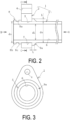
FIG. 2 is an explanatory diagram exemplifying the assembly ofFIG. 1 in a longitudinal cross-sectional view. -
FIG. 3 is a view in the direction of arrow A inFIG. 2 . -
FIG. 4 is a view in the direction of arrow B inFIG. 2 . -
FIG. 5 is a cross-sectional view taken along C-C inFIG. 2 . -
FIG. 6 is an explanatory diagram exemplifying a metal flange ofFIG. 2 in a perspective view. -
FIG. 7 is an explanatory diagram exemplifying a modified example of a metal flange in a perspective view. -
FIG. 8 is an explanatory diagram exemplifying an assembly according to another embodiment in a longitudinal cross-sectional view. -
FIG. 9 is a view in the direction of arrow D inFIG. 8 . -
FIG. 10 is an explanatory diagram exemplifying a forming device that manufactures the assembly. -
FIG. 11 is an explanatory diagram exemplifying one mold ofFIG. 10 in a plan view. -
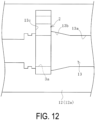
FIG. 12 is an explanatory view exemplifying a state in which the metal flange is disposed in an insert portion ofFIG. 11 . -
FIG. 13 is an explanatory diagram exemplifying a state in which molds ofFIG. 12 are clamped and then molten resin is injected into a cavity. -
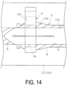
FIG. 14 is an explanatory diagram exemplifying a state in which assist gas is injected into the molten resin ofFIG. 13 . -
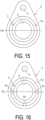
FIG. 15 is an explanatory view exemplifying a parting line of a resin pipe ofFIG. 4 . -
FIG. 16 is an explanatory view exemplifying a parting line of a resin pipe ofFIG. 9 . - Hereinafter, an assembly of a metal flange and a resin pipe and a method of manufacturing the assembly according to an embodiment of the present invention will be described based on embodiments illustrated in the drawings.
- As exemplified in
FIGS. 1 to 5 , an embodiment of anassembly 1 manufactured by the embodiment of the present invention is formed by externally fitting ametal flange 2 to aresin pipe 5 such that both are integrated. In the embodiment, theresin pipe 5 is a straight pipe having an outer diameter do and an inner diameter di, but there may be a case where theresin pipe 5 is a bent pipe. The outer diameter do is, for example, about 6 mm or more and 150 mm or less, and the inner diameter di is, for example, about 4 mm or more and 146 mm or less. - Both end portions of the
resin pipe 5 in a longitudinal direction are connected to various devices, joint parts, and the like. In the embodiment, as exemplified inFIG. 1 , the other longitudinal end portion of theresin pipe 5 is aninsertion portion 8 inserted into aflow path 11a of atarget device 11. Aseal member 8d disposed in theinsertion portion 8 abuts on an inner circumferential surface of theflow path 11a to ensure a sealing property between theresin pipe 5 and theflow path 11a. - One end surface of the
metal flange 2 abuts on an opposed surface of thetarget device 11, and afixing bolt 10 passing through amounting hole 4 of themetal flange 2 is screwed into a bolt hole of thetarget device 11. Thus, ajoint product 1 is connected and fixed to thetarget device 11. - The structure of the
assembly 1 will be described in detail below. - The
metal flange 2 includes aninsertion hole 3 into which theresin pipe 5 is inserted and themounting hole 4. Although various metals can be used as the material of themetal flange 2, aluminum or an aluminum alloy is preferable for weight reduction. A thickness t of themetal flange 2 is, for example, about 70% or more and 100% or less of the outer diameter do of theresin pipe 5. - As exemplified in
FIG. 5 , the surface of theinsertion hole 3 includes a large number ofprojections 3a and is unevenly formed. As exemplified inFIG. 6 , each of theprojections 3a extends linearly in parallel with the longitudinal direction of theresin pipe 5. Therespective projections 3a are preferably disposed at regular intervals in a circumferential direction. The number of theprojections 3a and a projection amount of theprojection 3a in a radial direction of theinsertion hole 3 are determined as appropriate. For example, the number of theprojections 3a is about 8 pieces or more and 32 pieces or less, and the projection amount is about several mm. - As in the
metal flange 2 exemplified inFIG. 7 , a specification in which therespective projections 3a are inclined with respect to the longitudinal direction of theresin pipe 5 to extend spirally can be employed. Alternatively, theprojections 3a extending in the circumferential direction of theinsertion hole 3 can be provided. To prevent themetal flange 2 externally fitted to theresin pipe 5 from being rotationally displaced about theresin pipe 5, at least oneprojection 3a (theprojection 3a not parallel to the circumferential direction of the resin pipe 5) extending in the longitudinal direction of theresin pipe 5 only needs to be provided on the surface of theinsertion hole 3. - The
resin pipe 5 includes apipe passage 6 passing through and extending in the longitudinal direction. As the resin forming theresin pipe 5, various known resins, such as nylon resin (66 nylon or the like), polypropylene, and ABS resin, are used. The type (specification) of the resin used for theresin pipe 5 is determined based on performance required for theresin pipe 5. For example, resin having excellent durability against a fluid flowing through thepipe passage 6 and durability against external impact, wear, ultraviolet rays, and the like is used. - In the case of the
resin pipe 5 required to have high pressure resistance, short fiber (for example, glass fiber or carbon fiber) is mixed with the resin at a predetermined percentage (for example, 30% parts by mass or more and 40% parts by mass or less per 100 parts by mass of the resin) for reinforcement. The size of the short fibers is, for example, about 0.001 mm or more and 1.0 mm or less in an outer diameter and about 0.01 mm or more and 10 mm or less in a length. - In the
insertion portion 8, enlarged-diameter portions resin pipe 5 in the circumferential direction are disposed to be separated in the longitudinal direction of theresin pipe 5. A portion between the respective enlarged-diameter portions seal groove 8a continuous over the entire circumference of the outer circumferential surface of theresin pipe 5 in the circumferential direction. Theseal member 8d, such as an O-ring, made of rubber or elastomer is fitted into theseal groove 8a. - Although a groove bottom of the
seal groove 8a can be located on the inner circumferential side of the outer diameter do, the groove bottom is preferably located at a position same as the outer diameter do or on the outer circumferential side of the outer diameter do to ensure a thickness of a circumferential wall of theresin pipe 5. When the groove bottom of theseal groove 8a is located on the inner circumferential side of the outer diameter do, the outer circumferential surfaces of the respective enlarged-diameter portions diameter portions - The
resin pipe 5 includes a fixinggroove 7 on the outer circumferential surface continuous over the entire circumference in the circumferential direction. Themetal flange 2 is fitted to the fixinggroove 7. The groove bottom of the fixinggroove 7 can be located on the inner circumferential side of the outer diameter do, but is preferably located at the position same as the outer diameter do or on the outer circumferential side of the outer diameter do to ensure the thickness of the circumferential wall of theresin pipe 5. As exemplified inFIG. 5 , the outer circumferential surface of the fixinggroove 7 enters the unevenness formed on the surface of theinsertion hole 3. - A
circumferential rib 9a is provided at a position separated from one enlarged-diameter portion 8c in the longitudinal direction of theresin pipe 5. Thecircumferential rib 9a is continuous over the entire circumference of the outer circumferential surface of theresin pipe 5 in the circumferential direction. The fixinggroove 7 is formed between one enlarged-diameter portion 8c and thecircumferential rib 9a. - That is, on one side of both ends of the
metal flange 2 in the longitudinal direction of theresin pipe 5, there is provided the annularcircumferential rib 9a projecting toward the outer circumferential side from the outer diameter do of theresin pipe 5. Thecircumferential rib 9a abuts on the surface of one end surface of themetal flange 2 over the entire circumference in the circumferential direction. - An effective length L (a minimum length with respect to the longitudinal direction of the resin pipe 5) of the
circumferential rib 9a is preferably 2 mm or more, and is about 2 mm or more and 20 mm or less. In addition, a projection amount h of thecircumferential rib 9a (a projection amount from the outer circumferential surface of the outer diameter do to the outer circumferential side) is preferably 2.0 mm or more and, for example, about 2.0 mm or more and 10.0 mm or less. - In the embodiment, the enlarged-
diameter portion 8c is provided on the other side of both ends of themetal flange 2 in the longitudinal direction of theresin pipe 5. The enlarged-diameter portion 8c projects toward the outer circumferential side from the outer diameter do of theresin pipe 5, abuts on the surface of the other end surface of themetal flange 2, and is continuous over the entire circumference of the outer circumferential surface of theresin pipe 5 in the circumferential direction. Therefore, the enlarged-diameter portion 8c also functions as thecircumferential rib 9a. However, the projection amount of the enlarged-diameter portion 8c from the outer circumferential surface of the outer diameter do toward the outer circumferential side is small and smaller than the projection amount h. Thecircumferential rib 9a only needs to be disposed on at least one side of both ends of themetal flange 2 in the longitudinal direction of theresin pipe 5, and a structure having thecircumferential rib 9a only on one side can be employed. - As exemplified in
FIGS. 8 and 9 , a specification in which alongitudinal rib 9b connected to thecircumferential rib 9a and extending to one side in the longitudinal direction of theresin pipe 5 is provided in addition to thecircumferential rib 9a can be employed. At least the threelongitudinal ribs 9b are disposed to be separated at regular intervals in the circumferential direction of theresin pipe 5. For example, the 4 or more and 12 or lesslongitudinal ribs 9b are disposed at regular intervals in the circumferential direction. - The respective
longitudinal ribs 9b are set to have substantially the same specifications. A length L1 of thelongitudinal rib 9b is, for example, about 2.0 mm or more and 50.0 mm or less. The projection amount h of thelongitudinal rib 9b from the outer diameter do is preferably 2 mm or more and may be equal to or less than the projection amount h of thecircumferential rib 9a. A width W of thelongitudinal rib 9b is, for example, about 2.0 mm or more and 30.0 mm or less. - The lateral cross-sectional shape of the
longitudinal rib 9b is not limited to the quadrangular shape as exemplified inFIG. 9 , but any polygonal shape including a semi-circular shape, a triangular shape, and the like can be employed. Thelongitudinal rib 9b having a lateral cross-sectional shape with no corner portion is advantageous to provide the improved durability of thelongitudinal rib 9b. - In the embodiment, the
longitudinal rib 9b has a substantially triangular shape inclined from the outer edge of thecircumferential rib 9a toward the outer circumferential surface of theresin pipe 5 in a longitudinal cross-sectional view. However, thelongitudinal rib 9b can have another shape, such as a quadrangular shape. To obtain a reinforcing effect for theresin pipe 5 while reducing the weight of theassembly 1, thelongitudinal rib 9b having a substantially triangular shape in a longitudinal cross-sectional view is preferably employed. - Hereinafter, an example of a procedure of a manufacturing method of manufacturing the
assembly 1 of the embodiment of the present invention will be described. - To manufacture the
assembly 1 exemplified inFIGS. 8 and 9 , a formingdevice 14 exemplified inFIG. 10 is used. The formingdevice 14 includes acylinder 14a that injects molten resin R into a mold 12 (cavity 13) and an assistgas injection unit 14b that injects an assist gas G into the mold 12 (cavity 13). - In the embodiment, the
mold 12 is constituted of onemold 12a and theother mold 12b assembled to one another. Themutual molds mold 12 is not limited to such a two split type, and various known types can be used. - As exemplified in
FIG. 11 , in themold 12, thecavity 13, which is a hollow, is formed, and a discharge portion of the assist gas G injected into thecavity 13 is also formed. To describe thecavity 13 in detail, in the mold 12 (12a, 12b), acavity body 13a for forming theresin pipe 5, arib forming cavity 13b for forming thecircumferential rib 9a and thelongitudinal rib 9b, and aninsert portion 13c for disposing themetal flange 2 are formed. Therib forming cavity 13b is formed to be connected to theinsert portion 13c, has a diameter larger than the outer diameter of thecavity body 13a, and is continuous over the entire circumference of the outer circumferential surface of thecavity body 13a in the circumferential direction. - The molten rein R filled in the
rib forming cavity 13b is cured to form thecircumferential rib 9a and thelongitudinal rib 9b. Therefore, when thecircumferential ribs 9a are formed on the respective sides of both end surfaces of themetal flange 2, therib forming cavities 13b are formed on the respective sides at both ends of theinsert portion 13c in the extension direction of thecavity body 13a. When thecircumferential rib 9a is formed only on one side of both end surfaces of themetal flange 2, therib forming cavity 13b is formed on only one side of theinsert portion 13c in the extension direction of thecavity body 13a. - The
projections 3a are provided on the surface of theinsertion hole 3 of themetal flange 2 to form the surface unevenly. Theprojections 3a may be provided by machining or manual work. - Next, as exemplified in
FIG. 12 , after themetal flange 2 is disposed in theinsert portion 13c, themutual molds mold 12. Then, the molten resin R is injected from thecylinder 14a to fill the cavity 13 (thecavity body 13a and therib forming cavity 13b) with the molten resin R as exemplified inFIG. 13 . - In the embodiment, as exemplified in
FIG. 14 , the assist gas G, such as nitrogen gas, is injected at a predetermined high pressure into thecavity body 13a filled with the molten resin R and is caused to pass through in the extension direction of thecavity body 13a. By the assist gas G passing through thecavity body 13a, excess molten resin is discharged from thecavity body 13a to form thepipe passage 6. - Thereafter, the molten resin R remaining in the
cavity 13 is cured to form theresin pipe 5. Simultaneously with the forming of theresin pipe 5, themetal flange 2 is fitted to the fixinggroove 7 continuous over the entire circumference of the outer circumferential surface of theresin pipe 5 in the circumferential direction, and the outer circumferential surface of the fixinggroove 7 is caused to enter the unevenness on the surface of theinsertion hole 3. Thecircumferential rib 9a and thelongitudinal rib 9b described above are formed on at least one side of both ends of themetal flange 2 in the longitudinal direction of theresin pipe 5. - The forming method using the assist gas G as an assist material is employed in the embodiment, but an appropriate material of other gases, liquid, such as water, and a solid, such as a metal ball and a resin ball, can be used as the assist material. The known appropriate mechanism is employed as the assist
gas injection unit 14b according to the type of the assist material. - To form the
resin pipe 5, various known forming methods that do not use an assist material can be employed. For example, in a state in which a core extending in the longitudinal direction of the cavity body is disposed on thecavity body 13a, the molten resin R is injected into thecavity 13, and then the core is removed to allow for forming thepipe passage 6 and forming theresin pipe 5. - With the
resin pipe 5 of a straight pipe, various forming methods can be employed. However, with theresin pipe 5 of a non-straight pipe, a forming method using an assist material is preferably employed. This is because a bent portion of theresin pipe 5 is easily formed by the forming method using the assist material. In theresin pipe 5 ofFIG. 4 , a dashed line PL exemplified inFIG. 15 serves as a parting line of themold 12, and in theresin pipe 5 ofFIG. 9 , the dashed line PL exemplified inFIG. 16 serves as a parting line of themold 12. - The
assembly 1 of the embodiment of the present invention has a structure in which themetal flange 2 is fitted into the fixinggroove 7 continuous over the entire circumference of the outer circumferential surface of theresin pipe 5 in the circumferential direction, and the outer circumferential surface of the fixinggroove 7 enters the unevenness on the surface of theinsertion hole 3. Therefore, it is advantageous to fix themetal flange 2 to theresin pipe 5 at a predetermined position without displacement. In theassembly 1 exemplified inFIGS. 1 to 6 , providing theprojections 3a on the surface of theinsertion hole 3 prevents themetal flange 2 from rotating around theresin pipe 5, and thecircumferential rib 9a and the enlarged-diameter portion 8c prevent themetal flange 2 from being displaced in the longitudinal direction of theresin pipe 5. - When the
metal flange 2 exemplified inFIG. 7 is used, theprojections 3a provided on the surface of theinsertion hole 3 prevent themetal flange 2 from rotating around theresin pipe 5, and also prevent themetal flange 2 from being displaced in the longitudinal direction of theresin pipe 5. Therefore, by providing theprojections 3a, it is possible to reduce a burden on thecircumferential rib 9a and the enlarged-diameter portion 8c that prevent themetal flange 2 from being displaced in the longitudinal direction of theresin pipe 5. - Further, since a structure in which the
circumferential rib 9a integrated with theresin pipe 5 described above is provided on at least one side of both ends of themetal flange 2 in the longitudinal direction of theresin pipe 5 is employed, stress generated in theresin pipe 5 at the fixed portion of themetal flange 2 and theresin pipe 5 is reduced by thecircumferential rib 9a. As a result, it is possible to suppress theresin pipe 5 from being damaged over time at the fixed portion of both, which is advantageous in improving the durability of the resin pipe 5 (assembly 1). - In particular, a service life of the
resin pipe 5 tends to be further short under the condition that a used internal pressure of theresin pipe 5 of 30 MPa or more, but the service life can be extended by applying the embodiment of the present invention. As theresin pipe 5 having the used internal pressure of 3.5 MPa or more (or 30 MPa or more), a pipe through which a refrigerant of an air conditioner mounted on an automobile flows can be exemplified. - The specification of including the above-described
longitudinal rib 9b in addition to thecircumferential rib 9a is advantageous in further improving the durability of the resin pipe 5 (assembly 1). Further, when thecircumferential ribs 9a are connected to both end surfaces of themetal flange 2, it is more advantageous to fix themetal flange 2 at a predetermined position of theresin pipe 5, and it is also advantageous to improve the durability of the resin pipe 5 (assembly 1). - When the
resin pipe 5 is too hard, it is disadvantageous to suppress damage over time, and therefore appropriate flexibility is required. Therefore, it is desirable that theresin pipe 5 is formed of, for example, 66 nylon and short fibers are mixed for reinforcement. -
- 1 Assembly
- 2 Metal flange
- 3 Insertion hole
- 3a Projection
- 4 Mounting hole
- 5 Resin pipe
- 6 Pipe passage
- 7 Fixing groove
- 8 Insertion portion
- 8a Seal groove
- 8b, 8c Enlarged-diameter portion
- 8d Seal material (O-ring)
- 9a Circumferential rib
- 9b Longitudinal rib
- 10 Fixing bolt
- 11 Target device
- 11a Flow path
- 12 (12a, 12b) Mold
- 13 Cavity
- 13a Cavity body
- 13b Rib forming cavity
- 13c Insert portion
- 14 Forming device
- 14a Cylinder
- 14b Assist gas injection unit
- R molten resin
- G assist gas
Claims (7)
- An assembly of a metal flange and a resin pipe in which the metal flange is externally fitted to and integrated with the resin pipe,the metal flange being fitted in a fixing groove continuous over an entire circumference of an outer circumferential surface of the resin pipe in a circumferential direction,unevenness being formed on a surface of an insertion hole of the metal flange into which the resin pipe is inserted, and an outer circumferential surface of the fixing groove entering the unevenness, anda circumferential rib being formed on at least one side of both ends of the metal flange in a longitudinal direction of the resin pipe, abutting on an end surface of the metal flange, having a diameter larger than an outer diameter of the resin pipe, and being continuous over the entire circumference of the outer circumferential surface of the resin pipe in the circumferential direction.
- The assembly of the metal flange and the resin pipe according to claim 1, comprising
a longitudinal rib connected to the circumferential rib and extending to one side in the longitudinal direction of the resin pipe. - The assembly of the metal flange and the resin pipe according to claim 2, wherein at least the three longitudinal ribs are separated at regular intervals in the circumferential direction of the resin pipe.
- The assembly of the metal flange and the resin pipe according to any one of claim 1 to claim 3, wherein the circumferential rib is formed on the other end side in the longitudinal direction of the resin pipe, abuts on an end surface of the metal flange, has a diameter larger than an outer diameter of the resin pipe, and is continuous over the entire circumference of the outer circumferential surface of the resin pipe in the circumferential direction.
- A method of manufacturing an assembly of a metal flange and a resin pipe in which the metal flange is externally fitted to and integrated with the resin pipe, the method comprising:forming unevenness on a surface of an insertion hole of the metal flange into which the resin pipe is inserted;disposing the metal flange in an insert portion provided in a cavity body of a mold for forming the resin pipe;forming a rib forming cavity on at least one side of both ends of the insert portion in an extension direction of the cavity body, the rib forming cavity being connected to the insert portion, having a diameter larger than an outer diameter of the cavity body, and being continuous over an entire circumference of an outer circumferential surface of the cavity body in a circumferential direction;injecting molten resin into the cavity body and the rib forming cavity in a state where the mold is clamped to form the resin pipe by curing the molten resin;fitting the metal flange into a fixing groove continuous over the entire circumference of the outer circumferential surface of the resin pipe in the circumferential direction;causing an outer circumferential surface of the fixing groove to enter the unevenness on the surface of the insertion hole; andforming a circumferential rib on at least one side of both ends of the metal flange in a longitudinal direction of the resin pipe, the circumferential rib abutting on an end surface of the metal flange, having a diameter larger than an outer diameter of the resin pipe, and being continuous over the entire circumference of the outer circumferential surface of the resin pipe in the circumferential direction.
- The method of manufacturing the assembly of the metal flange and the resin pipe according to claim 5, wherein after the molten resin is injected into the cavity body and the rib forming cavity, an assist material is injected into the cavity body filled with the molten resin and the assist material is caused to pass through in the extension direction of the cavity body.
- The method of manufacturing the assembly of the metal flange and the resin pipe according to claim 6, wherein an assist gas is used as the assist material.
Applications Claiming Priority (2)
| Application Number | Priority Date | Filing Date | Title |
|---|---|---|---|
| JP2021165568A JP2023056292A (en) | 2021-10-07 | 2021-10-07 | Assembly component between metal flange and resin pipe and manufacturing method of the same |
| PCT/JP2022/026295 WO2023058279A1 (en) | 2021-10-07 | 2022-06-30 | Assembly of metal flange and resin tube, and method for manufacturing said assembly |
Publications (2)
| Publication Number | Publication Date |
|---|---|
| EP4414592A1 true EP4414592A1 (en) | 2024-08-14 |
| EP4414592A4 EP4414592A4 (en) | 2025-08-13 |
Family
ID=85804103
Family Applications (1)
| Application Number | Title | Priority Date | Filing Date |
|---|---|---|---|
| EP22878151.4A Pending EP4414592A4 (en) | 2021-10-07 | 2022-06-30 | ARRANGEMENT OF METAL FLANGE AND RESIN PIPE AND METHOD FOR MANUFACTURING THIS ARRANGEMENT |
Country Status (5)
| Country | Link |
|---|---|
| US (1) | US20240377005A1 (en) |
| EP (1) | EP4414592A4 (en) |
| JP (1) | JP2023056292A (en) |
| CN (1) | CN117957394A (en) |
| WO (1) | WO2023058279A1 (en) |
Family Cites Families (12)
| Publication number | Priority date | Publication date | Assignee | Title |
|---|---|---|---|---|
| AU8599082A (en) * | 1981-07-16 | 1983-02-03 | Ryan Rubber Co. Pty. Ltd. | Composite flange-ended tubular element |
| JPH0622913B2 (en) * | 1989-07-07 | 1994-03-30 | 旭有機材工業株式会社 | FRP reinforced vinyl chloride resin pipe joint and method for producing the same |
| JPH0780922A (en) | 1993-09-09 | 1995-03-28 | Inoac Corp | Resin air tube with flange |
| JP2007078089A (en) * | 2005-09-14 | 2007-03-29 | Yokohama Rubber Co Ltd:The | Fitting for pressure pipe |
| KR100688676B1 (en) * | 2005-10-04 | 2007-03-02 | 두산인프라코어 주식회사 | Connection hose with flange |
| JP5373277B2 (en) * | 2007-10-31 | 2013-12-18 | 昭和電工株式会社 | Manufacturing method of pipe with flange |
| KR101342943B1 (en) * | 2010-11-30 | 2013-12-18 | 한라비스테온공조 주식회사 | Pipe connection joint |
| KR101595209B1 (en) * | 2015-06-29 | 2016-02-17 | 비케이엠 주식회사 | Flange assembly for connecting pipe |
| KR20190014832A (en) * | 2017-08-04 | 2019-02-13 | 최준호 | Fusion flange |
| CN208185694U (en) * | 2018-05-07 | 2018-12-04 | 立胜(厦门)塑胶管材有限公司 | A kind of highstrenghtpiston's flange |
| JP7147514B2 (en) * | 2018-11-30 | 2022-10-05 | 横浜ゴム株式会社 | Method for manufacturing resin pipe |
| JP7251455B2 (en) * | 2019-12-03 | 2023-04-04 | いすゞ自動車株式会社 | Hollow body molding method and hollow body molding apparatus |
-
2021
- 2021-10-07 JP JP2021165568A patent/JP2023056292A/en active Pending
-
2022
- 2022-06-30 CN CN202280060073.2A patent/CN117957394A/en active Pending
- 2022-06-30 EP EP22878151.4A patent/EP4414592A4/en active Pending
- 2022-06-30 US US18/691,674 patent/US20240377005A1/en active Pending
- 2022-06-30 WO PCT/JP2022/026295 patent/WO2023058279A1/en not_active Ceased
Also Published As
| Publication number | Publication date |
|---|---|
| CN117957394A (en) | 2024-04-30 |
| JP2023056292A (en) | 2023-04-19 |
| WO2023058279A1 (en) | 2023-04-13 |
| US20240377005A1 (en) | 2024-11-14 |
| EP4414592A4 (en) | 2025-08-13 |
Similar Documents
| Publication | Publication Date | Title |
|---|---|---|
| US11338484B2 (en) | Member joining method | |
| CA2711112C (en) | High temperature progressive cavity motor or pump component and method of fabrication | |
| RU2640147C2 (en) | Connecting device, pipes containing such connection device for pipeline for a fluid environment for air or space craft, and method of manufacturing such device | |
| JP6987140B2 (en) | Improved antistatic pressure tank | |
| WO2017194215A1 (en) | Method for producing a charge air tube | |
| US11460131B2 (en) | Sealant injection nut | |
| US20180093421A1 (en) | Tubular body | |
| US11613978B2 (en) | Erosion-resistant inserts for flow equipment | |
| CN101341361A (en) | Liquid pipeline and method of manufacturing the same | |
| US20240377005A1 (en) | Assembly of metal flange and resin pipe and method of manufacturing assembly | |
| KR101674949B1 (en) | Lining Pipe Adaptor Apparatus | |
| CN120650541A (en) | Vulcanization bonding hose assembly and preparation method | |
| CN118140045A (en) | Method for fixing a bushing in a blade root of a wind turbine blade and end cap for use in the method | |
| US11433583B2 (en) | Method of manufacturing resin pipe | |
| EP2333386B1 (en) | Valve body with inliner and method for producing same | |
| KR102108437B1 (en) | Valve lining devices and lining valves | |
| US20240384820A1 (en) | Assembly of resin pipe and metal member and method of manufacturing assembly | |
| CN113165234B (en) | Method for producing resin pipe | |
| JP6573322B2 (en) | Plastic pipe | |
| JP6602219B2 (en) | Manufacturing method for synthetic resin pipes | |
| EP3382253B1 (en) | Gas-tight plastic pipe branch | |
| US20100109214A1 (en) | Assembly For Transporting Pressurized Fluid and Method of Manufacture | |
| JPH108536A (en) | Pipe with spiral guideway | |
| CN220668804U (en) | Corrosion-resistant pipeline | |
| KR101968845B1 (en) | Mold for Rubber Hose |
Legal Events
| Date | Code | Title | Description |
|---|---|---|---|
| STAA | Information on the status of an ep patent application or granted ep patent |
Free format text: STATUS: THE INTERNATIONAL PUBLICATION HAS BEEN MADE |
|
| PUAI | Public reference made under article 153(3) epc to a published international application that has entered the european phase |
Free format text: ORIGINAL CODE: 0009012 |
|
| STAA | Information on the status of an ep patent application or granted ep patent |
Free format text: STATUS: REQUEST FOR EXAMINATION WAS MADE |
|
| 17P | Request for examination filed |
Effective date: 20240422 |
|
| AK | Designated contracting states |
Kind code of ref document: A1 Designated state(s): AL AT BE BG CH CY CZ DE DK EE ES FI FR GB GR HR HU IE IS IT LI LT LU LV MC MK MT NL NO PL PT RO RS SE SI SK SM TR |
|
| DAV | Request for validation of the european patent (deleted) | ||
| DAX | Request for extension of the european patent (deleted) | ||
| A4 | Supplementary search report drawn up and despatched |
Effective date: 20250710 |
|
| RIC1 | Information provided on ipc code assigned before grant |
Ipc: F16L 23/024 20060101AFI20250704BHEP Ipc: B29C 45/14 20060101ALI20250704BHEP Ipc: B29C 45/57 20060101ALI20250704BHEP Ipc: F16L 11/04 20060101ALI20250704BHEP Ipc: B29C 45/17 20060101ALI20250704BHEP Ipc: F16L 23/028 20060101ALI20250704BHEP Ipc: F16L 23/12 20060101ALI20250704BHEP Ipc: B29L 23/00 20060101ALN20250704BHEP Ipc: B29K 705/00 20060101ALN20250704BHEP Ipc: B29L 31/24 20060101ALN20250704BHEP |