EP4414587A1 - Harmonic drive with flex spline end clamps - Google Patents
Harmonic drive with flex spline end clamps Download PDFInfo
- Publication number
- EP4414587A1 EP4414587A1 EP24157280.9A EP24157280A EP4414587A1 EP 4414587 A1 EP4414587 A1 EP 4414587A1 EP 24157280 A EP24157280 A EP 24157280A EP 4414587 A1 EP4414587 A1 EP 4414587A1
- Authority
- EP
- European Patent Office
- Prior art keywords
- housing
- drive
- flex spline
- center
- clamp
- Prior art date
- Legal status (The legal status is an assumption and is not a legal conclusion. Google has not performed a legal analysis and makes no representation as to the accuracy of the status listed.)
- Pending
Links
Images


Classifications
-
- F—MECHANICAL ENGINEERING; LIGHTING; HEATING; WEAPONS; BLASTING
- F16—ENGINEERING ELEMENTS AND UNITS; GENERAL MEASURES FOR PRODUCING AND MAINTAINING EFFECTIVE FUNCTIONING OF MACHINES OR INSTALLATIONS; THERMAL INSULATION IN GENERAL
- F16H—GEARING
- F16H49/00—Other gearings
- F16H49/001—Wave gearings, e.g. harmonic drive transmissions
-
- B—PERFORMING OPERATIONS; TRANSPORTING
- B64—AIRCRAFT; AVIATION; COSMONAUTICS
- B64C—AEROPLANES; HELICOPTERS
- B64C13/00—Control systems or transmitting systems for actuating flying-control surfaces, lift-increasing flaps, air brakes, or spoilers
- B64C13/24—Transmitting means
- B64C13/38—Transmitting means with power amplification
-
- B—PERFORMING OPERATIONS; TRANSPORTING
- B64—AIRCRAFT; AVIATION; COSMONAUTICS
- B64C—AEROPLANES; HELICOPTERS
- B64C13/00—Control systems or transmitting systems for actuating flying-control surfaces, lift-increasing flaps, air brakes, or spoilers
- B64C13/24—Transmitting means
- B64C13/26—Transmitting means without power amplification or where power amplification is irrelevant
- B64C13/28—Transmitting means without power amplification or where power amplification is irrelevant mechanical
- B64C13/34—Transmitting means without power amplification or where power amplification is irrelevant mechanical using toothed gearing
-
- F—MECHANICAL ENGINEERING; LIGHTING; HEATING; WEAPONS; BLASTING
- F16—ENGINEERING ELEMENTS AND UNITS; GENERAL MEASURES FOR PRODUCING AND MAINTAINING EFFECTIVE FUNCTIONING OF MACHINES OR INSTALLATIONS; THERMAL INSULATION IN GENERAL
- F16H—GEARING
- F16H49/00—Other gearings
- F16H49/001—Wave gearings, e.g. harmonic drive transmissions
- F16H2049/003—Features of the flexsplines therefor
Definitions
- the application is directed to a harmonic drive and more specifically to a harmonic drive with flex spline end clamps.
- a flex spline shaft may have end sections formed as cup and hat shapes, that is, with a flange that is turned either inwardly or outwardly, to secure the flex spline within a drive housing. These configurations may reduce a usable volume within the drive.
- a flex spline shaft may instead have pancake style, e.g., flat, end sections. Such sections may have a reduced torque capacity and reduced efficiency compared with the turned end sections.
- a harmonic drive including a housing extending axially from a first outer end to a second outer end, wherein the housing has radial outer and inner walls that extend axially between the first and second outer ends of the housing to define an annular channel therebetween, the annular channel having a first end at the first outer end of the housing and a second end at the second outer end of housing, and the first and second ends of the annular channel taper toward the first and second outer ends of the housing; a flex spline that extends axially between first and second ends and has a radial outer surface, and the first and second ends of the flex spline taper radially outwardly, wherein the flex spline is located within the annular channel so that the first end of the flex spline is located within the first end of the annular channel and the second end of the flex spline is located within the second end of the annular channel; a first clamp that is clamped against the first end of the annular channel
- the flex spline ends and channel define facing surfaces with cooperating ribs and slots that interact with each other to prevent rotation of the flex spline relative to the channel during operation of the drive.
- first and second clamps are annular rings having a C-shaped cross section that, respectively open towards the first and second outer ends of the housing; and the first and second clamps define an outer profile that tapers to match the taper of the first and second ends of the annular channel.
- the drive further includes first fasteners that engage the first clamp and urge the first clamp toward the first outer end of the housing to clamp the first clamp at the first end of the annular channel; and second fasteners that engage the second clamp and urge the second clamp toward the second outer end of the housing to clamp the second clamp at the second end of the annular channel.
- first and second clamps have an axial inner end that defines a radially extending wall with circumferentially distributed apertures through which the first and second fasteners extend.
- first and second clamps have a threaded inner profile; and the first and second fasteners are screws.
- the radial inner wall defines: an axially extending center channel; and a radially extending center gap at an axial center of the housing that segments the radial inner wall into a first segment that extends from the first end of the housing to the center gap and a second segment that extends from the second end of the housing to the center gap.
- the drive further includes an input shaft located within the center channel, having a first end that extends axially past the first outer end of the housing and a second end that extends axially past the second outer end of the housing.
- the drive further includes a first input shaft bearing disposed within the center channel, between the input shaft and the first segment of the radial inner wall; and a second input shaft bearing disposed within the center channel, between the input shaft and the second segment of the radial inner wall.
- the flex spline includes a center portion having an outer facing spline; the input shaft has a center portion that defines a wave generator profile and extends through the center gap; and a wave generator bearing set, having inner and outer races and roller bearings between the inner and outer races, wherein the inner race is disposed against the center portion of the input shaft and the outer race is disposed against the center portion of the flex spline.
- the drive further includes first and second roller bearing retainer clips disposed at axial ends of the wave generator bearing set; first and second thrust bearings that are adjacent to the first and second retainer clips and are seated on the input shaft; and first and second thrust bearing retainer clips that are adjacent to the first and second thrust bearings and the first and second segments of the radial inner wall, and are seated on the input shaft.
- the drive further includes an output shaft surrounds the center portion of the flex spline and includes: an inner facing spline that engages the outer facing spline of the flex spline; and at least one output shaft bearing disposed between the output shaft and the radial outer wall.
- the housing is formed by: a first housing member that extends axially between the first outer end of the housing and a first inner end of the first housing member; and a second housing member that extends axially between the second outer end of the housing and a second inner end of the second housing member that faces the first inner end of the first housing member.
- the first and second inner ends of the first and second housing members define a center aperture that extends through a portion of the radial outer wall; and the output shaft has an output flange that extends radially outwardly through the center aperture in the radial outer wall, wherein the center aperture extends around the drive to provide for a predetermined rotational range of the output flange during operation of the drive.
- an aircraft including: a control surface; a motor; and a drive as defined above coupled to the control surface, wherein the motor is coupled to the input shaft and the control surface is coupled to the output flange.
- control surface is a wing flap.
- the embodiments disclosed herein provide a harmonic drive 10 with a flex spline 20 having tapered spline ends 20A, 20B that are flexible ( FIG. 3 ).
- Tapered clamps 30, 40 are positioned against the tapered spline ends 20A, 20B ( FIG. 4 ).
- the flex spline 20 is disposed in an annular channel 50 in a drive housing 60 ( FIG. 5 ).
- the channel 50 has tapered channel ends 50A, 50B, which receive the tapered spline ends 20A, 20B and the tapered clamps 30, 40.
- the tapered clamps 30, 40 are configured to clamp the tapered spline ends 20A, 20B to the housing 60 by axially clamping (or urging) the ends of the flex spline 20 to the outer ends of the housing 60.
- an aircraft 100 includes a control surface 110, which may be a flap of a wing 115, a motor 120 and the drive 10 coupled to the control surface 110.
- the motor 120 is coupled to an input shaft 140 of the drive 10 and the control surface 110 is coupled to an output flange 150 of an output shaft 160 of the drive 10.
- the drive 10 has a housing 60 that extends from a first outer end 60A to a second outer end 60B.
- the housing 60 is formed by a first housing member 180 that extends axially between the first outer end 60A of the housing 60 and a first inner end 180A of the first housing member 180.
- a second housing member 200 of the housing 60 extends axially between the second outer end 60B of the housing 60 and a second inner end 200B of the second housing member 200 that faces the first inner end 180A of the first housing member 180.
- the housing 60 has a radial outer wall 210 with outer and inner facing surfaces 210A, 210B, and a radial inner wall 215 with outer and inner facing surfaces 215A, 215B.
- the outer facing surface 210A of the outer wall 210 is the radial outer surface of the housing 60, e.g., between the opposing ends 60A, 60B.
- the radial outer and inner walls 210, 215 extend axially between the first and second outer ends 60A, 60B of the housing 60.
- the annular channel 50 is defined between the radial outer and inner walls 210, 215, e.g., between the inner surface 210B of the outer wall 210 and the outer surface 215A of the inner wall 210.
- the annular channel 50 has a first end 50A at the first outer end 60A of the housing 60 and a second end 50B at the second outer end 60B of the housing 60. As indicated, the first and second ends 50A, 50B of the annular channel 50 taper so that they are narrower, e.g., converge, toward the first and second outer ends 60A, 60B of the housing 60.
- the outer surfaces 20A, 20B of the flex spline ends is smooth as well as the outer surfaces 215A of the channel ends 50A, 50B.
- the radial inner surface 20E of the spline 20, at axial outer surfaces 20A, 20B of flex spline ends are formed with axially extending ribs 20E1 or tongues that interface with axially extending slots or grooves 215S1 formed along the outer surface 215A of the channel ends 50A, 50B, where the channel ends 50A, 50B form shoulders 20S to support the spline ends 20A, 20B.
- the flex spline ends and channel define facing surfaces, e.g., which face each other, with cooperating ribs and slots that interact with each other. This mating configuration prevents rotation of the flex spline relative to the housing 60 during operation.
- the radial inner wall 215 defines an axially extending center channel 230, e.g., by its inner surface 215B.
- a radially extending center gap 240 at an axial center of the housing 60 segments the radial inner wall 215 into a first segment 215A1 that extends from the first end 60A of the housing 60 to the center gap 240 and a second segment 215B that extends from the second end 60B of the housing 60 to the center gap 240.
- the input shaft 140 is located within the center channel 230.
- the input shaft 140 has a first end 140A that extends axially past the first outer end 60A of the housing 60 and a second end 140B that extends axially past the second outer end 60B of the housing 60.
- the input shaft 140 has a center portion 140C with an outer surface 140D that defines a wave generator profile and extends through the center gap 240. That is, the surface 140D is smooth and shaped as an ellipse to provide harmonic motion as it rotates.
- a first input shaft bearing 250A is disposed within the center channel 230.
- the first input shaft bearing 250A is located between the input shaft 140 and the first segment 215A1 of the radial inner wall 215A.
- a second input shaft bearing 250B is disposed within the center channel 230.
- the second input shaft bearing 250B is between the input shaft 140 and the second segment 215B of the radial inner wall 215.
- the input shaft bearings 250A, 250B are ball bearings.
- the first and second inner ends 180A, 200B of the first and second housing members 180, 200 define a center aperture 280 that extends through a portion of the radial outer wall 210.
- the output flange 150 of the output shaft 160 extends radially outwardly through the center aperture 280 in the radial outer wall 210.
- the center aperture 280 extends around the drive 10 to provide for a predetermined rotational range of the output flange 150 during operation of the drive 10.
- the drive 10 includes the flex spline 20 (or flex spline shaft) that extends axially, includes first and second ends 20A, 20B, a center portion 20C, and has radial outer and inner surfaces 20D, 20E ( FIG. 6 ).
- the first and second ends 20A, 20B of the flex spline 20 taper radially outwardly.
- the center portion 20C has an outer facing spline 20F.
- the first clamp 30 is disposed against the radial outer surface 20D of the flex spline 20 at the first end 20A of the flex spline 20.
- the second clamp 40 is disposed against the radial outer surface 20D of the flex spline 20 at the second end 20B of the flex spline 20.
- the flex spline 20 and clamps 30, 40 are located within the annular channel 50.
- the first end 20A of the flex spline 20 and the first clamp 30 are located within the first end 50A of the annular channel 50 and the second end 20B of the flex spline 20 and the second clamp 40 are located within the second end 50B of the annular channel 50.
- the first clamp 30 is between the radial outer surface 20D of the flex spline 20 and the radial outer wall 210 the annular channel 50.
- the second clamp 40 is between the radial outer surface 20D of the flex spline 20 and the radial outer wall 210 of the annular channel 50.
- the clamps have an inner tapered surface that functions to clamp the tapered section of the flex spline toward the outwardly facing surface of the ground housings.
- the clamps are pulled axially by fasteners (discussed below), and the inner taper of the clamp functions to clamp the flex spline's tapered section to the outwardly facing inner surface of the ground housings.
- the outer surface of the clamp has clearance to the housing.
- the first and second clamps 30, 40 are annular rings having outer surfaces 30A, 40A that define a C-shaped cross section that opens toward the first and second outer ends 60A, 60B of the housing 60.
- the first and second clamps 30, 40 define an outer profile that tapers to match the taper of the first and second ends 50A, 50B of the annular channel 50.
- the first and second clamps 30, 40 have first and second inner surface 30B, 40B that are threaded.
- An axial inner end of the first and second clamps 30, 40 define radially extending walls 30C, 40C with circumferentially distributed apertures 30D, 40D.
- the drive 10 includes first fasteners 290A that engage the first clamp 30 and urge the first clamp 30 toward the first outer end 60A of the housing 60 to clamp the first clamp 30 between the flex spline 20 and the radial outer wall 210 of the annular channel 50.
- Second fasteners 290B engage the second clamp 40 and urge the second clamp 40 toward the second outer end 60B of the housing 60 to clamp the second clamp 40 between the flex spline 20 and the radial outer wall 210 of the annular channel 50.
- first and second fasteners 290A, 290B are threaded screws that engage the threaded profile of the first and second clamps 30, 40.
- the first and second fasteners 290A, 290B extend through the circumferentially distributed apertures 30D, 40D of the first and second clamps 30, 40 when urging the first and second clamps 30, 40 toward the first and second outer ends 60A, 60B of the housing 60.
- the output shaft 160 surrounds the center portion 20C of the flex spline 20.
- the output shaft 160 includes an inner facing spline 160A that engages the outer facing spline 20F ( FIG. 3 ) of the flex spline 20.
- First and second output shaft bearings 300A, 300B is disposed between first and second axial outer portions 160B, 160C of the output shaft 160 and the radial outer wall 210.
- a wave generator bearing set 310 is radially between the radial inner surface 20E of the flex spline 20 and the center portion 140C of the input shaft 140.
- the bearing set 310 has roller bearings 320 between outer and inner races 330A, 330B.
- the outer race 330A is disposed against the center portion 20C of the flex spline 20 and the inner race 330B is disposed against the center portion 140C of the input shaft 140, axially adjacent to the surface 140D formed with the wave generator profile.
- the shaft aside from the wave generator profile, as a circular cross section along its length, though the ends 140A, 140B may be keyed or geared to mate with the motor 120 (FIG. 120).
- the bearing set 310 extends axially between first and second roller bearing retainer clips 340A, 340B.
- First and second thrust bearings 350A, 350B are axially adjacent to the first and second retainer clips 340A, 340B and are seated on the input shaft 140.
- First and second thrust bearing retainer clips 360A, 360B are axially adjacent to the first and second thrust bearings 350A, 350B and the first and second segments 215A1, 215B1 of the radially inner wall 215 and are seated on the input shaft 140.
- the wave generator bearing set 310 harmonically engages the flex spline 20 with rotation of the input shaft 140 as a function of the wave generator profile of the outer surface 140D of the center portion 140C of the input shaft 140 to drive the output shaft 160.
Landscapes
- Engineering & Computer Science (AREA)
- General Engineering & Computer Science (AREA)
- Mechanical Engineering (AREA)
- Automation & Control Theory (AREA)
- Aviation & Aerospace Engineering (AREA)
- Retarders (AREA)
Abstract
A harmonic drive, having a housing (60) extending from first to second outer ends (60A, 60B0, the housing has radial outer and inner walls (210, 215) that extend axially between the first and second outer ends of the housing to define an annular channel (50) having first and second ends (50A, 50B) that taper toward the first and second outer ends of the housing; a flex spline (20) that extends axially between first and second ends (20A, 20B) and has a radial outer surface (20D), and the first and second ends of the flex spline taper radially outwardly, the flex spline is located within the annular channel so that the first end of the flex spline is located within the first end of the annular channel and the second end of the flex spline is located within the second end of the annular channel; and first and second clamps (30, 40) that are clamped against the first and second ends of the annular channel.
Description
- The application is directed to a harmonic drive and more specifically to a harmonic drive with flex spline end clamps.
- Applications for a small diameter, high ratio gear can benefit from a harmonic drive. A flex spline shaft may have end sections formed as cup and hat shapes, that is, with a flange that is turned either inwardly or outwardly, to secure the flex spline within a drive housing. These configurations may reduce a usable volume within the drive. A flex spline shaft may instead have pancake style, e.g., flat, end sections. Such sections may have a reduced torque capacity and reduced efficiency compared with the turned end sections.
- Disclosed is a harmonic drive, including a housing extending axially from a first outer end to a second outer end, wherein the housing has radial outer and inner walls that extend axially between the first and second outer ends of the housing to define an annular channel therebetween, the annular channel having a first end at the first outer end of the housing and a second end at the second outer end of housing, and the first and second ends of the annular channel taper toward the first and second outer ends of the housing; a flex spline that extends axially between first and second ends and has a radial outer surface, and the first and second ends of the flex spline taper radially outwardly, wherein the flex spline is located within the annular channel so that the first end of the flex spline is located within the first end of the annular channel and the second end of the flex spline is located within the second end of the annular channel; a first clamp that is clamped against the first end of the annular channel; and a second clamp that is clamped against the second end of the annular channel.
- In embodiments, the flex spline ends and channel define facing surfaces with cooperating ribs and slots that interact with each other to prevent rotation of the flex spline relative to the channel during operation of the drive.
- In embodiments, the first and second clamps are annular rings having a C-shaped cross section that, respectively open towards the first and second outer ends of the housing; and the first and second clamps define an outer profile that tapers to match the taper of the first and second ends of the annular channel.
- In embodiments, the drive further includes first fasteners that engage the first clamp and urge the first clamp toward the first outer end of the housing to clamp the first clamp at the first end of the annular channel; and second fasteners that engage the second clamp and urge the second clamp toward the second outer end of the housing to clamp the second clamp at the second end of the annular channel.
- In embodiments, the first and second clamps have an axial inner end that defines a radially extending wall with circumferentially distributed apertures through which the first and second fasteners extend.
- In embodiments, the first and second clamps have a threaded inner profile; and the first and second fasteners are screws.
- In embodiments, the radial inner wall defines: an axially extending center channel; and a radially extending center gap at an axial center of the housing that segments the radial inner wall into a first segment that extends from the first end of the housing to the center gap and a second segment that extends from the second end of the housing to the center gap.
- In embodiments, the drive further includes an input shaft located within the center channel, having a first end that extends axially past the first outer end of the housing and a second end that extends axially past the second outer end of the housing.
- In embodiments, the drive further includes a first input shaft bearing disposed within the center channel, between the input shaft and the first segment of the radial inner wall; and a second input shaft bearing disposed within the center channel, between the input shaft and the second segment of the radial inner wall.
- In embodiments, the flex spline includes a center portion having an outer facing spline; the input shaft has a center portion that defines a wave generator profile and extends through the center gap; and a wave generator bearing set, having inner and outer races and roller bearings between the inner and outer races, wherein the inner race is disposed against the center portion of the input shaft and the outer race is disposed against the center portion of the flex spline.
- In embodiments, the drive further includes first and second roller bearing retainer clips disposed at axial ends of the wave generator bearing set; first and second thrust bearings that are adjacent to the first and second retainer clips and are seated on the input shaft; and first and second thrust bearing retainer clips that are adjacent to the first and second thrust bearings and the first and second segments of the radial inner wall, and are seated on the input shaft.
- In embodiments, the drive further includes an output shaft surrounds the center portion of the flex spline and includes: an inner facing spline that engages the outer facing spline of the flex spline; and at least one output shaft bearing disposed between the output shaft and the radial outer wall.
- In embodiments, the housing is formed by: a first housing member that extends axially between the first outer end of the housing and a first inner end of the first housing member; and a second housing member that extends axially between the second outer end of the housing and a second inner end of the second housing member that faces the first inner end of the first housing member.
- In embodiments, the first and second inner ends of the first and second housing members define a center aperture that extends through a portion of the radial outer wall; and the output shaft has an output flange that extends radially outwardly through the center aperture in the radial outer wall, wherein the center aperture extends around the drive to provide for a predetermined rotational range of the output flange during operation of the drive.
- Further disclosed is an aircraft including: a control surface; a motor; and a drive as defined above coupled to the control surface, wherein the motor is coupled to the input shaft and the control surface is coupled to the output flange.
- In embodiments, the control surface is a wing flap.
- The present disclosure is illustrated by way of example and not limited in the accompanying figures in which like reference numerals indicate similar elements.
-
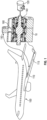
FIG. 1 shows a sectional view of a harmonic drive according to an embodiment operationally connected to an aircraft wing flap; -
FIG. 2 shows the sectional view of the harmonic drive; -
FIG. 3 shows a flex spline shaft that is utilized in the harmonic drive; -
FIG. 4 shows the flex spline shaft with end clamps; -
FIG. 5 shows a detail identified inFIG. 2 of a portion of the harmonic drive; and -
FIG. 6 shows a detail identified inFIG. 5 of a portion of the harmonic drive. - Aspects of the disclosed embodiments will now be addressed with reference to the figures. Aspects in any one figure is equally applicable to any other figure unless otherwise indicated. Aspects illustrated in the figures are for purposes of supporting the disclosure and are not in any way intended on limiting the scope of the invention, which is defined by the claims. Any sequence of numbering in the figures is for reference purposes only.
- As disclosed in greater detail below, the embodiments disclosed herein provide a
harmonic drive 10 with aflex spline 20 havingtapered spline ends FIG. 3 ). Taperedclamps tapered spline ends FIG. 4 ). Theflex spline 20 is disposed in anannular channel 50 in a drive housing 60 (FIG. 5 ). Thechannel 50 hastapered channel ends tapered spline ends tapered clamps tapered clamps tapered spline ends housing 60 by axially clamping (or urging) the ends of theflex spline 20 to the outer ends of thehousing 60. - Turning to
FIG. 1 , anaircraft 100 includes acontrol surface 110, which may be a flap of awing 115, amotor 120 and thedrive 10 coupled to thecontrol surface 110. Themotor 120 is coupled to aninput shaft 140 of thedrive 10 and thecontrol surface 110 is coupled to anoutput flange 150 of anoutput shaft 160 of thedrive 10. - Turning to
Fig. 2 , additional details of theharmonic drive 10 are shown. Thedrive 10 has ahousing 60 that extends from a firstouter end 60A to a secondouter end 60B. Thehousing 60 is formed by afirst housing member 180 that extends axially between the firstouter end 60A of thehousing 60 and a firstinner end 180A of thefirst housing member 180. Asecond housing member 200 of thehousing 60 extends axially between the secondouter end 60B of thehousing 60 and a secondinner end 200B of thesecond housing member 200 that faces the firstinner end 180A of thefirst housing member 180. - The
housing 60 has a radialouter wall 210 with outer and inner facingsurfaces inner wall 215 with outer and inner facingsurfaces surface 210A of theouter wall 210 is the radial outer surface of thehousing 60, e.g., between theopposing ends inner walls outer ends housing 60. Theannular channel 50 is defined between the radial outer andinner walls inner surface 210B of theouter wall 210 and theouter surface 215A of theinner wall 210. Theannular channel 50 has afirst end 50A at the firstouter end 60A of thehousing 60 and asecond end 50B at the secondouter end 60B of thehousing 60. As indicated, the first andsecond ends annular channel 50 taper so that they are narrower, e.g., converge, toward the first and secondouter ends housing 60. - In the illustrated embodiment, the
outer surfaces outer surfaces 215A of thechannel ends inner surface 20E of thespline 20, at axialouter surfaces outer surface 215A of thechannel ends 50B form shoulders 20S to support thespline ends housing 60 during operation. - The radial
inner wall 215 defines an axially extendingcenter channel 230, e.g., by itsinner surface 215B. A radially extendingcenter gap 240 at an axial center of thehousing 60 segments the radialinner wall 215 into a first segment 215A1 that extends from thefirst end 60A of thehousing 60 to thecenter gap 240 and asecond segment 215B that extends from thesecond end 60B of thehousing 60 to thecenter gap 240. Theinput shaft 140 is located within thecenter channel 230. Theinput shaft 140 has afirst end 140A that extends axially past the firstouter end 60A of thehousing 60 and asecond end 140B that extends axially past the secondouter end 60B of thehousing 60. Theinput shaft 140 has acenter portion 140C with anouter surface 140D that defines a wave generator profile and extends through thecenter gap 240. That is, thesurface 140D is smooth and shaped as an ellipse to provide harmonic motion as it rotates. - A first input shaft bearing 250A is disposed within the
center channel 230. The first input shaft bearing 250A is located between theinput shaft 140 and the first segment 215A1 of the radialinner wall 215A. A second input shaft bearing 250B is disposed within thecenter channel 230. The second input shaft bearing 250B is between theinput shaft 140 and thesecond segment 215B of the radialinner wall 215. Theinput shaft bearings - The first and second inner ends 180A, 200B of the first and
second housing members center aperture 280 that extends through a portion of the radialouter wall 210. Theoutput flange 150 of theoutput shaft 160 extends radially outwardly through thecenter aperture 280 in the radialouter wall 210. Thecenter aperture 280 extends around thedrive 10 to provide for a predetermined rotational range of theoutput flange 150 during operation of thedrive 10. - Turning to
FIGS. 3 , thedrive 10 includes the flex spline 20 (or flex spline shaft) that extends axially, includes first and second ends 20A, 20B, acenter portion 20C, and has radial outer andinner surfaces FIG. 6 ). The first and second ends 20A, 20B of theflex spline 20 taper radially outwardly. Thecenter portion 20C has an outer facingspline 20F. As shown inFIG. 4 , thefirst clamp 30 is disposed against the radialouter surface 20D of theflex spline 20 at thefirst end 20A of theflex spline 20. Thesecond clamp 40 is disposed against the radialouter surface 20D of theflex spline 20 at thesecond end 20B of theflex spline 20. - As shown in
FIG. 5 , theflex spline 20 and clamps 30, 40 are located within theannular channel 50. Thefirst end 20A of theflex spline 20 and thefirst clamp 30 are located within thefirst end 50A of theannular channel 50 and thesecond end 20B of theflex spline 20 and thesecond clamp 40 are located within thesecond end 50B of theannular channel 50. Thefirst clamp 30 is between the radialouter surface 20D of theflex spline 20 and the radialouter wall 210 theannular channel 50. Thesecond clamp 40 is between the radialouter surface 20D of theflex spline 20 and the radialouter wall 210 of theannular channel 50. The clamps have an inner tapered surface that functions to clamp the tapered section of the flex spline toward the outwardly facing surface of the ground housings. The clamps are pulled axially by fasteners (discussed below), and the inner taper of the clamp functions to clamp the flex spline's tapered section to the outwardly facing inner surface of the ground housings. In the embodiments, the outer surface of the clamp has clearance to the housing. - The first and
second clamps outer surfaces housing 60. The first andsecond clamps annular channel 50. The first andsecond clamps inner surface second clamps walls apertures 30D, 40D. - The
drive 10 includesfirst fasteners 290A that engage thefirst clamp 30 and urge thefirst clamp 30 toward the firstouter end 60A of thehousing 60 to clamp thefirst clamp 30 between theflex spline 20 and the radialouter wall 210 of theannular channel 50.Second fasteners 290B engage thesecond clamp 40 and urge thesecond clamp 40 toward the secondouter end 60B of thehousing 60 to clamp thesecond clamp 40 between theflex spline 20 and the radialouter wall 210 of theannular channel 50. - More specifically, the first and
second fasteners second clamps second fasteners apertures 30D, 40D of the first andsecond clamps second clamps housing 60. - The configuration of the taper of the first and second ends 20A, 20B of the
flex spline 20, the first andsecond clamps annular channel 50, lock theflex spline 20 within thedrive 10 during operation of thedrive 10. This occurs without requiring the ends 20A, 20B of thespline 20 to be turned outwardly in a hat shape or inwardly in a cup shape, which otherwise reduces the usable volume within thedrive 10. This also provide for better securing of the of thespline 20 within thedrive 10 compared with a pancake-shaped spline ends. - Turning to
FIG. 6 , theoutput shaft 160 surrounds thecenter portion 20C of theflex spline 20. Theoutput shaft 160 includes aninner facing spline 160A that engages the outer facingspline 20F (FIG. 3 ) of theflex spline 20. First and secondoutput shaft bearings outer portions output shaft 160 and the radialouter wall 210. - A wave generator bearing set 310 is radially between the radial
inner surface 20E of theflex spline 20 and thecenter portion 140C of theinput shaft 140. The bearing set 310 hasroller bearings 320 between outer and inner races 330A, 330B. The outer race 330A is disposed against thecenter portion 20C of theflex spline 20 and the inner race 330B is disposed against thecenter portion 140C of theinput shaft 140, axially adjacent to thesurface 140D formed with the wave generator profile. It is to be appreciated that the shaft, aside from the wave generator profile, as a circular cross section along its length, though the ends 140A, 140B may be keyed or geared to mate with the motor 120 (FIG. 120). The bearing set 310 extends axially between first and second rollerbearing retainer clips second thrust bearings second retainer clips input shaft 140. First and second thrust bearing retainer clips 360A, 360B are axially adjacent to the first andsecond thrust bearings inner wall 215 and are seated on theinput shaft 140. The wave generator bearing set 310 harmonically engages theflex spline 20 with rotation of theinput shaft 140 as a function of the wave generator profile of theouter surface 140D of thecenter portion 140C of theinput shaft 140 to drive theoutput shaft 160. - The terminology used herein is for the purpose of describing particular embodiments only and is not intended to be limiting of the present disclosure. As used herein, the singular forms "a", "an" and "the" are intended to include the plural forms as well, unless the context clearly indicates otherwise. It will be further understood that the terms "comprises" and/or "comprising," when used in this specification, specify the presence of stated features, integers, steps, operations, elements, and/or components, but do not preclude the presence or addition of one or more other features, integers, steps, operations, element components, and/or groups thereof.
- Those of skill in the art will appreciate that various example embodiments are shown and described herein, each having certain features in the particular embodiments, but the present disclosure is not thus limited. Rather, the present disclosure can be modified to incorporate any number of variations that fall within the scope of the invention as defined by the claims. Additionally, while various embodiments of the present disclosure have been described, it is to be understood that aspects of the present disclosure may include only some of the described embodiments. Accordingly, the present disclosure is not to be seen as limited by the foregoing description, but is only limited by the scope of the appended claims.
Claims (15)
- A harmonic drive, comprising:a housing (60) extending axially from a first outer end (60A) to a second outer end (60B),wherein the housing has radial outer and inner walls (210, 215) that extend axially between the first and second outer ends of the housing to define an annular channel (50) therebetween, the annular channel having a first end (50A) at the first outer end of the housing and a second end (50B) at the second outer end of housing, and the first and second ends of the annular channel taper toward the first and second outer ends of the housing;a flex spline (20) that extends axially between first and second ends and has a radial outer surface (20D), and the first and second ends (20A, 20B) of the flex spline taper radially outwardly,wherein the flex spline is located within the annular channel so that the first end of the flex spline is located within the first end of the annular channel and the second end of the flex spline is located within the second end of the annular channel;a first clamp (30) that is clamped against the first end of the annular channel; anda second clamp (40) that is clamped against the second end of the annular channel.
- The drive of claim 1, wherein:
the flex spline ends and channel define facing surfaces with cooperating ribs (20E1) and slots (21551) that interact with each other to prevent rotation of the flex spline relative to the channel during operation of the drive. - The drive of claim 1, wherein:the first and second clamps are annular rings having a C-shaped cross section that, respectively open towards the first and second outer ends of the housing; andthe first and second clamps define an outer profile that tapers to match the taper of the first and second ends of the annular channel.
- The drive of claim 2, further comprising:first fasteners (290A) that engage the first clamp and urge the first clamp toward the first outer end of the housing to clamp the first clamp at the first end of the annular channel; andsecond fasteners (290B) that engage the second clamp and urge the second clamp toward the second outer end of the housing to clamp the second clamp at the second end of the annular channel.
- The drive of claim 4, wherein:
the first and second clamps have an axial inner end that defines a radially extending wall with circumferentially distributed apertures (30D, 40D) through which the first and second fasteners extend. - The drive of claim 5, wherein:the first and second clamps have a threaded inner profile; andthe first and second fasteners are screws.
- The drive of claim 6, wherein:
the radial inner wall defines:an axially extending center channel (230); anda radially extending center gap (240) at an axial center of the housing that segments the radial inner wall into a first segment (215A1) that extends from the first end of the housing to the center gap and a second segment (215B 1) that extends from the second end of the housing to the center gap. - The drive of claim 7, further comprising:
an input shaft (140) located within the center channel, having a first end that extends axially past the first outer end of the housing and a second end that extends axially past the second outer end of the housing. - The drive of claim 8, further comprising:a first input shaft bearing (250A) disposed within the center channel, between the input shaft and the first segment of the radial inner wall; anda second input shaft bearing (250B) disposed within the center channel, between the input shaft and the second segment of the radial inner wall.
- The drive of claim 9, wherein:the flex spline includes a center portion (20C) having an outer facing spline;the input shaft has a center portion (140C) that defines a wave generator profile and extends through the center gap; anda wave generator bearing set (310), having inner and outer races and roller bearings between the inner and outer races, wherein the inner race (330B) is disposed against the center portion of the input shaft and the outer race (330A) is disposed against the center portion of the flex spline.
- The drive of claim 10, further including:first and second roller bearing retainer clips (340A, 340B) disposed at axial ends of the wave generator bearing set;first and second thrust bearings (350A, 350B) that are adjacent to the first and second retainer clips and are seated on the input shaft; andfirst and second thrust bearing retainer clips that are adjacent to the first and second thrust bearings and the first and second segments of the radial inner wall, and are seated on the input shaft.
- The drive of claim 10, further comprising:
an output shaft (160) surrounds the center portion of the flex spline and includes:an inner facing spline (160A) that engages the outer facing spline of the flex spline; andat least one output shaft bearing disposed between the output shaft and the radial outer wall. - The drive of claim 12, wherein the housing is formed by:a first housing member (180) that extends axially between the first outer end of the housing and a first inner end of the first housing member; anda second housing member (200) that extends axially between the second outer end of the housing and a second inner end of the second housing member that faces the first inner end of the first housing member.
- The drive of claim 13, wherein:the first and second inner ends of the first and second housing members define a center aperture that extends through a portion of the radial outer wall; andthe output shaft has an output flange that extends radially outwardly through the center aperture in the radial outer wall, wherein the center aperture extends around the drive to provide for a predetermined rotational range of the output flange during operation of the drive.
- An aircraft including:a control surface (110);a motor (120); andthe drive (10) of any preceding claim coupled to the control surface, wherein the motor is coupled to the input shaft and the control surface is coupled to the output flange, and optionally whereinthe control surface is a wing flap.
Applications Claiming Priority (1)
| Application Number | Priority Date | Filing Date | Title |
|---|---|---|---|
| US18/168,178 US12215769B2 (en) | 2023-02-13 | 2023-02-13 | Harmonic drive with flex spline end clamps |
Publications (1)
| Publication Number | Publication Date |
|---|---|
| EP4414587A1 true EP4414587A1 (en) | 2024-08-14 |
Family
ID=89941005
Family Applications (1)
| Application Number | Title | Priority Date | Filing Date |
|---|---|---|---|
| EP24157280.9A Pending EP4414587A1 (en) | 2023-02-13 | 2024-02-13 | Harmonic drive with flex spline end clamps |
Country Status (3)
| Country | Link |
|---|---|
| US (1) | US12215769B2 (en) |
| EP (1) | EP4414587A1 (en) |
| CA (1) | CA3228873A1 (en) |
Citations (3)
| Publication number | Priority date | Publication date | Assignee | Title |
|---|---|---|---|---|
| EP3312475A2 (en) * | 2016-10-20 | 2018-04-25 | Hamilton Sundstrand Corporation | Compound harmonic drive assembly |
| EP3792524A1 (en) * | 2019-09-10 | 2021-03-17 | Hamilton Sundstrand Corporation | Compound harmonic gearbox configured for continuous output rotation |
| CA3160866A1 (en) * | 2021-08-11 | 2023-02-11 | Hamilton Sundstrand Corporation | Compound harmonic gear system with dual output arms |
Family Cites Families (8)
| Publication number | Priority date | Publication date | Assignee | Title |
|---|---|---|---|---|
| FR1326700A (en) * | 1961-05-08 | 1963-05-10 | United Shoe Machinery Corp | Energy transmission mechanism |
| US3523488A (en) * | 1968-11-01 | 1970-08-11 | Usm Corp | Fluidic stepping motors |
| JP2003176857A (en) | 2001-12-11 | 2003-06-27 | Teijin Seiki Co Ltd | Flex spline for meshing gear device and meshing gear device having the flex spline |
| DE112011105695T5 (en) | 2011-09-29 | 2014-07-17 | Harmonic Drive Systems Inc. | Corrugated gear with a tapered flexible externally toothed gear |
| US20160305528A1 (en) * | 2015-04-20 | 2016-10-20 | Nabors Lux Finance 2 Sarl | Harmonic Gear Drive |
| CN113819213A (en) * | 2021-09-22 | 2021-12-21 | 珠海格力电器股份有限公司 | Harmonic reducer ware flexbile gear subassembly and harmonic reducer ware |
| EP4390178A1 (en) * | 2022-12-23 | 2024-06-26 | Hamilton Sundstrand Corporation | Strain wave drive |
| EP4390179A1 (en) * | 2022-12-23 | 2024-06-26 | Hamilton Sundstrand Corporation | Strain wave drive |
-
2023
- 2023-02-13 US US18/168,178 patent/US12215769B2/en active Active
-
2024
- 2024-02-12 CA CA3228873A patent/CA3228873A1/en active Pending
- 2024-02-13 EP EP24157280.9A patent/EP4414587A1/en active Pending
Patent Citations (3)
| Publication number | Priority date | Publication date | Assignee | Title |
|---|---|---|---|---|
| EP3312475A2 (en) * | 2016-10-20 | 2018-04-25 | Hamilton Sundstrand Corporation | Compound harmonic drive assembly |
| EP3792524A1 (en) * | 2019-09-10 | 2021-03-17 | Hamilton Sundstrand Corporation | Compound harmonic gearbox configured for continuous output rotation |
| CA3160866A1 (en) * | 2021-08-11 | 2023-02-11 | Hamilton Sundstrand Corporation | Compound harmonic gear system with dual output arms |
Also Published As
| Publication number | Publication date |
|---|---|
| CA3228873A1 (en) | 2025-04-17 |
| US12215769B2 (en) | 2025-02-04 |
| US20240271687A1 (en) | 2024-08-15 |
Similar Documents
| Publication | Publication Date | Title |
|---|---|---|
| JP4339782B2 (en) | Fixing device for fixing the impeller to the shaft | |
| US5531564A (en) | Centrifugal pump | |
| US6629816B2 (en) | Non-contacting clearance seal for high misalignment applications | |
| US7305767B2 (en) | Shaft and hub mounting system and method | |
| JP2001514994A (en) | Preloaded bearing assembly for mounting and retaining aircraft propeller blades. | |
| CN100520008C (en) | Booster impeller assembly | |
| EP3112692B1 (en) | Centrifugal compressor, turbocharger with said centrifugal compressor, and method for manufacturing said centrifugal compressor | |
| US20050089364A1 (en) | Mounting device | |
| US4543704A (en) | Method for anchoring a machine element coaxially on a rotary shaft | |
| US20100192927A1 (en) | method and apparatus for controlling a compound bearing assembly of a centrifugal compressor | |
| US20030094073A1 (en) | Method for mounting a sleeve on a shaft and a sleeve device for such mounting | |
| US20170037911A1 (en) | Flexible coupling means, a mechanical transmission, and an aircraft | |
| CA3228873A1 (en) | Harmonic drive with flex spline end clamps | |
| EP3693579B1 (en) | Starter locking assembly and method | |
| CN113423962B (en) | Rotor bearings for wind turbines | |
| CN109751193B (en) | Wind generating set | |
| EP3647541B1 (en) | Split vernier ring for turbine rotor stack assembly | |
| US10422420B2 (en) | Mounting arrangement for a planet gear | |
| US20080144986A1 (en) | Sleeve mounting system and method | |
| CN108138906A (en) | Assemblies of crankshaft end sections with flywheel and guide bearings and associated engine components | |
| BR102024000926A2 (en) | HARMONIC DRIVE, AND, AIRCRAFT | |
| EP2895785B1 (en) | Rotor machine having oil slinger system | |
| US10934842B2 (en) | Turbocharger and method for assembling turbocharger | |
| US12146534B2 (en) | Flyweight damper | |
| RU2269007C1 (en) | Unit of connection of disk with engine rotor shaft |
Legal Events
| Date | Code | Title | Description |
|---|---|---|---|
| PUAI | Public reference made under article 153(3) epc to a published international application that has entered the european phase |
Free format text: ORIGINAL CODE: 0009012 |
|
| STAA | Information on the status of an ep patent application or granted ep patent |
Free format text: STATUS: THE APPLICATION HAS BEEN PUBLISHED |
|
| AK | Designated contracting states |
Kind code of ref document: A1 Designated state(s): AL AT BE BG CH CY CZ DE DK EE ES FI FR GB GR HR HU IE IS IT LI LT LU LV MC ME MK MT NL NO PL PT RO RS SE SI SK SM TR |
|
| STAA | Information on the status of an ep patent application or granted ep patent |
Free format text: STATUS: REQUEST FOR EXAMINATION WAS MADE |
|
| 17P | Request for examination filed |
Effective date: 20250214 |