EP3693579B1 - Starter locking assembly and method - Google Patents
Starter locking assembly and method Download PDFInfo
- Publication number
- EP3693579B1 EP3693579B1 EP19208654.4A EP19208654A EP3693579B1 EP 3693579 B1 EP3693579 B1 EP 3693579B1 EP 19208654 A EP19208654 A EP 19208654A EP 3693579 B1 EP3693579 B1 EP 3693579B1
- Authority
- EP
- European Patent Office
- Prior art keywords
- rotor shaft
- starter
- recited
- threadedly engaged
- retainer
- Prior art date
- Legal status (The legal status is an assumption and is not a legal conclusion. Google has not performed a legal analysis and makes no representation as to the accuracy of the status listed.)
- Active
Links
- 239000007858 starting material Substances 0.000 title claims description 31
- 238000000034 method Methods 0.000 title claims description 14
- 238000000429 assembly Methods 0.000 description 5
- 230000000712 assembly Effects 0.000 description 5
- 230000006835 compression Effects 0.000 description 2
- 238000007906 compression Methods 0.000 description 2
- 239000012530 fluid Substances 0.000 description 2
- 239000000314 lubricant Substances 0.000 description 2
- 238000009434 installation Methods 0.000 description 1
- 230000014759 maintenance of location Effects 0.000 description 1
- 238000012986 modification Methods 0.000 description 1
- 230000004048 modification Effects 0.000 description 1
- 230000003068 static effect Effects 0.000 description 1
Images


Classifications
-
- F—MECHANICAL ENGINEERING; LIGHTING; HEATING; WEAPONS; BLASTING
- F02—COMBUSTION ENGINES; HOT-GAS OR COMBUSTION-PRODUCT ENGINE PLANTS
- F02C—GAS-TURBINE PLANTS; AIR INTAKES FOR JET-PROPULSION PLANTS; CONTROLLING FUEL SUPPLY IN AIR-BREATHING JET-PROPULSION PLANTS
- F02C7/00—Features, components parts, details or accessories, not provided for in, or of interest apart form groups F02C1/00 - F02C6/00; Air intakes for jet-propulsion plants
- F02C7/26—Starting; Ignition
- F02C7/268—Starting drives for the rotor, acting directly on the rotor of the gas turbine to be started
- F02C7/27—Fluid drives
-
- F—MECHANICAL ENGINEERING; LIGHTING; HEATING; WEAPONS; BLASTING
- F02—COMBUSTION ENGINES; HOT-GAS OR COMBUSTION-PRODUCT ENGINE PLANTS
- F02C—GAS-TURBINE PLANTS; AIR INTAKES FOR JET-PROPULSION PLANTS; CONTROLLING FUEL SUPPLY IN AIR-BREATHING JET-PROPULSION PLANTS
- F02C7/00—Features, components parts, details or accessories, not provided for in, or of interest apart form groups F02C1/00 - F02C6/00; Air intakes for jet-propulsion plants
- F02C7/26—Starting; Ignition
- F02C7/268—Starting drives for the rotor, acting directly on the rotor of the gas turbine to be started
- F02C7/275—Mechanical drives
- F02C7/277—Mechanical drives the starter being a separate turbine
-
- F—MECHANICAL ENGINEERING; LIGHTING; HEATING; WEAPONS; BLASTING
- F16—ENGINEERING ELEMENTS AND UNITS; GENERAL MEASURES FOR PRODUCING AND MAINTAINING EFFECTIVE FUNCTIONING OF MACHINES OR INSTALLATIONS; THERMAL INSULATION IN GENERAL
- F16D—COUPLINGS FOR TRANSMITTING ROTATION; CLUTCHES; BRAKES
- F16D1/00—Couplings for rigidly connecting two coaxial shafts or other movable machine elements
- F16D1/06—Couplings for rigidly connecting two coaxial shafts or other movable machine elements for attachment of a member on a shaft or on a shaft-end
- F16D1/076—Couplings for rigidly connecting two coaxial shafts or other movable machine elements for attachment of a member on a shaft or on a shaft-end by clamping together two faces perpendicular to the axis of rotation, e.g. with bolted flanges
-
- F—MECHANICAL ENGINEERING; LIGHTING; HEATING; WEAPONS; BLASTING
- F16—ENGINEERING ELEMENTS AND UNITS; GENERAL MEASURES FOR PRODUCING AND MAINTAINING EFFECTIVE FUNCTIONING OF MACHINES OR INSTALLATIONS; THERMAL INSULATION IN GENERAL
- F16D—COUPLINGS FOR TRANSMITTING ROTATION; CLUTCHES; BRAKES
- F16D1/00—Couplings for rigidly connecting two coaxial shafts or other movable machine elements
- F16D1/10—Quick-acting couplings in which the parts are connected by simply bringing them together axially
-
- F—MECHANICAL ENGINEERING; LIGHTING; HEATING; WEAPONS; BLASTING
- F16—ENGINEERING ELEMENTS AND UNITS; GENERAL MEASURES FOR PRODUCING AND MAINTAINING EFFECTIVE FUNCTIONING OF MACHINES OR INSTALLATIONS; THERMAL INSULATION IN GENERAL
- F16H—GEARING
- F16H57/00—General details of gearing
- F16H57/08—General details of gearing of gearings with members having orbital motion
-
- F—MECHANICAL ENGINEERING; LIGHTING; HEATING; WEAPONS; BLASTING
- F05—INDEXING SCHEMES RELATING TO ENGINES OR PUMPS IN VARIOUS SUBCLASSES OF CLASSES F01-F04
- F05D—INDEXING SCHEME FOR ASPECTS RELATING TO NON-POSITIVE-DISPLACEMENT MACHINES OR ENGINES, GAS-TURBINES OR JET-PROPULSION PLANTS
- F05D2260/00—Function
- F05D2260/30—Retaining components in desired mutual position
- F05D2260/31—Retaining bolts or nuts
Definitions
- This application relates to locking assemblies that may be utilized in an air turbine starter.
- Air turbine starters are known, and include a turbine rotor which receives compressed air from a source to drive the turbine rotor. As the turbine rotor rotates, it rotates a planetary gear system, and ultimately an output shaft. The output shaft is connected to a prime mover, such as a gas turbine engine in an aircraft, and is utilized as a starter to begin rotation of the gas turbine engine core.
- a prime mover such as a gas turbine engine in an aircraft
- the rotor shaft receives a sun gear of the planetary gear system and a bearing assembly.
- the sun gear and bearing assembly may be clamped to the rotor shaft by a locking assembly.
- a starter for a gas turbine engine includes a rotor shaft rotatable about an axis and including an inner bore extending from an axial end of the rotor shaft with respect to the axis.
- a sun gear is received on the rotor shaft.
- a lock nut is received against an axial end face of the sun gear and threadedly engaged with an outer diameter of the rotor shaft.
- a retainer is positioned to bias the nut against the axial end face and includes a projection portion threadedly engaged with the rotor shaft in the inner bore. A bolt through the projection portion is threadedly engaged with the rotor shaft.
- US 6,681,579 B2 describes an air turbine starter with fluid flow control.
- US 8,613,142 B2 describes methods for cluster gear timing.
- US 2003/0099540 A1 describes a stationary roller shaft.
- FIG. 1 schematically illustrates a starter 20 for a gas turbine engine 34.
- An air source 24 delivers high pressure air into an inlet 26.
- the high pressure air flows across a turbine rotor 28, causing the turbine rotor 28 to rotate.
- the output shaft 32 may be utilized as an engine starter in some examples, to start operation of a main gas turbine engine 34.
- the output shaft 32 drives the gas turbine engine through an accessory gearbox 36.
- a clutch 38 is provided between the planetary gear system 30 and the output shaft 32.
- the planetary gear system 30 includes a sun gear 40 that is driven by a rotor shaft 42 and rotates with the turbine rotor 28.
- the sun gear 40 drives a plurality of planet gears 43, which drive a ring gear 44.
- the ring gear 44 drives the output shaft 32 through the clutch 38.
- FIG 2 illustrates a turbine assembly section 46 of the starter 20 shown in Figure 1 .
- the turbine rotor 28 is rotatable with the rotor shaft 42 about a centerline axis A.
- a stator section 48 is provided axially aft (downstream with respect to the working fluid) of the rotor 28.
- the stator section 48 includes a hub 50 and a gear cage housing 52 radially outward of the hub 50.
- the stator section 48 may include other stationary components of the starter 20.
- a bearing assembly 54 is provided radially between the rotor shaft 42 and the hub 50 and includes one or more ball bearings 56.
- the inner races of the ball bearings 56 rotate with the rotor shaft 42, while the outer races of the ball bearings 56 are static and support the hub 50.
- the sun gear 40 is provided axially aft of the aftmost ball bearing 56.
- a locking assembly 58 (shown schematically) is provided axially aft of the sun gear 40 to clamp the sun gear 40 and the bearing assembly 54 to the rotor shaft 42 to achieve desired compression and balancing.
- Prior art locking assemblies 58 may include customized nuts, which may be expensive and require long assembly times, often requiring shims and/or other additional components for installation.
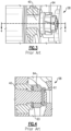
- Figure 3 illustrates prior art locking assembly including a castellated nut 64 positioned to clamp a sun gear 40.
- Figure 4 illustrates a cross-sectional view of the locking assembly 58 illustrated in Figure 3 .
- the castellated nut 64 is aligned with openings in the rotor shaft 42, and a pin 61 is placed through the castellated portion (grooves or slots in upper face) of the nut 64 and into openings in the rotor shaft 42.
- a shim 63 is then placed to fill any gap between the nut 64 and the sun gear 40 to achieve the desired compression. Applicant has identified the drawbacks of the prior art locking assemblies.
- a customized nut is fastened to the rotor shaft against the sun gear and receives a ring having geometrical aspect to interface with a corresponding surfaces on the rotor shaft and nut for positive locking of the nut onto the rotor shaft.
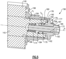
- FIG 5 illustrates a locking assembly 158 for clamping the sun gear 140 and bearing assembly (not shown; see Figure 2 ) to a rotor shaft 142 of the starter 20 shown in Figures 1 and 2 in some examples.
- the rotor shaft 142 includes an inner bore 160 extending from an axial end face 162 of the rotor shaft 142.
- a lock nut 164 is received against an axial end face 166 of the sun gear 140 for clamping the sun gear 140 to the rotor shaft 142.
- An inner diameter of the lock nut 164 is threadedly engaged with an outer diameter of the rotor shaft 142.
- the lock nut 164 may be an off-the-shelf lock nut having a threaded inner diameter for engaging a threaded outer diameter of the rotor shaft 142.
- the starter 20 is used as an example in the disclosure, other rotating machines may benefit from this disclosure.
- a retainer 168 is positioned to bias the lock nut 164 against the axial end face 166.
- the retainer 168 includes a projection portion 170 threadedly engaged with the rotor shaft 142 in the inner bore 160.
- the nut 164 is threadedly engaged with the rotor shaft 142 in a first threaded direction T1
- the retainer 168 is threadedly engaged with the inner bore 160 in a second threaded direction T2 opposite the first threaded direction T1 for secure locking.
- the retainer 168 may include left hand threads, and the nut 164 may include right hand threads, and vice versa.
- a bolt 172 extends axially along the axis A through the projection portion 170 and threadedly engages with the rotor shaft 142. In some examples, as shown, the bolt 172 threadedly engages the shaft 142 through a threaded helicoil insert 174. In other examples, the bolt 172 threadedly engages the rotor shaft 142 directly.
- the projection portion 170 may extend from a cap portion 176 that includes a flange 178.
- the flange 178 abuts an end face 180 of the nut 164 at an interface radially outward of the rotor shaft 142.
- a groove 182 is provided radially between the flange 178 and the projection portion 170, and the end face 162 of the rotor shaft 142 extends into the groove 182 when the locking assembly 158 is assembled.
- An opening 183 of the retainer 168 extends through the cap portion 176 and the projection portion 170 and is centered about the axis A to receive the bolt 172.
- the cap portion 176 may include a hexagonally shaped portion 177 for engagement with tools for assembling and disassembling.
- a head 185 of the bolt 172 may be received against an end surface 187 of the cap portion in some examples.
- the bore 160 is a counterbore, including a first portion 184 and a second portion 186 spaced inward from the end face 162 from the first portion 184.
- the first portion 184 has a greater diameter than the second portion 186.
- the projection portion 170 is threadedly engaged with the first portion 184
- the bolt 172 is threadedly engaged with the second portion 186. That is, the counterboring allows both the projection portion 170 and the bolt 172 to threadedly engage the rotor shaft 142.
- the locking assembly 158 therefore threadedly engages both inner and outer portions of the rotor shaft 142 for secure locking and a balanced rotor shaft 142.
- Figure 6 illustrates a second example locking assembly 258 substantially similar to the locking assembly 158 of Figure 5 .
- a washer 288 is provided axially between the cap portion 276 and the end face 280 of the nut 264.
- the washer 288 is radially outward of the rotor shaft 142.
- the washer 288 transfers the securing force from the retainer 268 to the nut 264.
- the washer 288 is received against an inner face 290 of cap portion 276. As shown, all or a portion of the cap portion 276 may be hexagonally shaped.
- Figure 7 illustrates a third example locking assembly 358 substantially similar to the locking assembly 258 of Figure 6 , except the washer 388 is received in a recess 392 of the cap portion 376.
- the recess 392 is provided where the inner face 390 meets a radially outer face 394 in some examples.
- FIG 8 illustrates a flow chart of a method 400 for locking a bearing assembly 54 and a sun gear 40/140/240/340 onto a rotor shaft 42/142/242/342 of a starter 20 for a gas turbine engine 34.
- the method 400 includes providing the bearing assembly 54 and the sun gear 40/140/240/340 on the rotor shaft 42/142/242/342.
- the method 400 includes fastening a lock nut 164/264/364 onto the rotor shaft 42/142/242/342 and against an end face 166/266/366 of the sun gear 40/140/240/340.
- the method 400 includes fastening a retainer 168/268/368 onto the rotor shaft 42/142/242/342 to bias the lock nut 164/264/364 against the end face 166/266/366, which may include threadedly engaging a projection portion 170/270/370 of the retainer 168/268/368 in a bore 160/260/360 of the rotor shaft 42/142/242/342.
- the method 400 includes fastening a bolt 172/272/372 onto the rotor shaft 42/142/242/342 through the projection portion 170/270/370.
- the method may include providing a washer 288/388 between the retainer 168/268/368 and the lock nut 164/264/364.
- step 404 may be performed with a low friction lubricant, and step 406 and step 408 may be performed dry or with the same lubricant that is used to lubricate the starter 20, including the bearing assembly 54.
- the above disclosed assemblies and methods allow for clamping of the sun gear and bearing assembly using an offthe-shelf lock nut. Additional retention of the locknut is achieved through a bolted retainer. The disclosed assemblies and methods therefore result in reduced cost of components and assembly. Locking is achieved through the threading of components to the rotor shaft, without the need for custom nuts, shims, pins, or positive locking geometry components.
Landscapes
- Engineering & Computer Science (AREA)
- General Engineering & Computer Science (AREA)
- Mechanical Engineering (AREA)
- Chemical & Material Sciences (AREA)
- Combustion & Propulsion (AREA)
- Retarders (AREA)
- Turbine Rotor Nozzle Sealing (AREA)
Description
- This application relates to locking assemblies that may be utilized in an air turbine starter.
- Air turbine starters are known, and include a turbine rotor which receives compressed air from a source to drive the turbine rotor. As the turbine rotor rotates, it rotates a planetary gear system, and ultimately an output shaft. The output shaft is connected to a prime mover, such as a gas turbine engine in an aircraft, and is utilized as a starter to begin rotation of the gas turbine engine core.
- The rotor shaft receives a sun gear of the planetary gear system and a bearing assembly. The sun gear and bearing assembly may be clamped to the rotor shaft by a locking assembly.
- A starter for a gas turbine engine, according to the invention, includes a rotor shaft rotatable about an axis and including an inner bore extending from an axial end of the rotor shaft with respect to the axis. A sun gear is received on the rotor shaft. A lock nut is received against an axial end face of the sun gear and threadedly engaged with an outer diameter of the rotor shaft. A retainer is positioned to bias the nut against the axial end face and includes a projection portion threadedly engaged with the rotor shaft in the inner bore. A bolt through the projection portion is threadedly engaged with the rotor shaft.
- These and other features may be best understood from the following specification and drawings, the following of which is a brief description.
US 6,681,579 B2 describes an air turbine starter with fluid flow control.US 8,613,142 B2 describes methods for cluster gear timing.US 2003/0099540 A1 describes a stationary roller shaft. -
-
Figure 1 schematically illustrates a starter for a gas turbine engine. -
Figure 2 illustrates a partial section of the starter ofFigure 1 . -
Figure 3 illustrates a prior art locking assembly. -
Figure 4 illustrates a cross sectional view of the locking assembly ofFigure 3 . -
Figure 5 illustrates an example locking assembly. -
Figure 6 illustrates a second example locking assembly. -
Figure 7 illustrates a third example locking assembly. -
Figure 8 illustrates a flow chart of a method for locking a bearing assembly and a sun gear onto a rotor shaft of a starter for a gas turbine engine. -
Figure 1 schematically illustrates astarter 20 for agas turbine engine 34. Anair source 24 delivers high pressure air into aninlet 26. The high pressure air flows across aturbine rotor 28, causing theturbine rotor 28 to rotate. As theturbine rotor 28 rotates, it rotates aplanetary gear system 30, and ultimately theoutput shaft 32. Theoutput shaft 32 may be utilized as an engine starter in some examples, to start operation of a maingas turbine engine 34. In some examples, as shown, theoutput shaft 32 drives the gas turbine engine through anaccessory gearbox 36. As shown, in some examples, aclutch 38 is provided between theplanetary gear system 30 and theoutput shaft 32. - The
planetary gear system 30 includes asun gear 40 that is driven by arotor shaft 42 and rotates with theturbine rotor 28. During engine starts, thesun gear 40 drives a plurality ofplanet gears 43, which drive aring gear 44. Thering gear 44 drives theoutput shaft 32 through theclutch 38. -
Figure 2 illustrates aturbine assembly section 46 of thestarter 20 shown inFigure 1 . Theturbine rotor 28 is rotatable with therotor shaft 42 about a centerline axis A. Astator section 48 is provided axially aft (downstream with respect to the working fluid) of therotor 28. Thestator section 48 includes ahub 50 and a gear cage housing 52 radially outward of thehub 50. Alternatively or additionally, thestator section 48 may include other stationary components of thestarter 20. - A
bearing assembly 54 is provided radially between therotor shaft 42 and thehub 50 and includes one ormore ball bearings 56. The inner races of theball bearings 56 rotate with therotor shaft 42, while the outer races of theball bearings 56 are static and support thehub 50. Thesun gear 40 is provided axially aft of the aftmost ball bearing 56. A locking assembly 58 (shown schematically) is provided axially aft of thesun gear 40 to clamp thesun gear 40 and thebearing assembly 54 to therotor shaft 42 to achieve desired compression and balancing. Priorart locking assemblies 58 may include customized nuts, which may be expensive and require long assembly times, often requiring shims and/or other additional components for installation. -
Figure 3 illustrates prior art locking assembly including a castellatednut 64 positioned to clamp asun gear 40. -
Figure 4 illustrates a cross-sectional view of thelocking assembly 58 illustrated inFigure 3 . The castellatednut 64 is aligned with openings in therotor shaft 42, and apin 61 is placed through the castellated portion (grooves or slots in upper face) of thenut 64 and into openings in therotor shaft 42. Ashim 63 is then placed to fill any gap between thenut 64 and thesun gear 40 to achieve the desired compression. Applicant has identified the drawbacks of the prior art locking assemblies. - In another prior art locking assembly (not shown), a customized nut is fastened to the rotor shaft against the sun gear and receives a ring having geometrical aspect to interface with a corresponding surfaces on the rotor shaft and nut for positive locking of the nut onto the rotor shaft.
-
Figure 5 illustrates alocking assembly 158 for clamping thesun gear 140 and bearing assembly (not shown; seeFigure 2 ) to arotor shaft 142 of thestarter 20 shown inFigures 1 and 2 in some examples. It should be understood that like reference numerals identify corresponding or similar elements throughout the several drawings. Therotor shaft 142 includes aninner bore 160 extending from anaxial end face 162 of therotor shaft 142. Alock nut 164 is received against anaxial end face 166 of thesun gear 140 for clamping thesun gear 140 to therotor shaft 142. An inner diameter of thelock nut 164 is threadedly engaged with an outer diameter of therotor shaft 142. Thelock nut 164 may be an off-the-shelf lock nut having a threaded inner diameter for engaging a threaded outer diameter of therotor shaft 142. Although thestarter 20 is used as an example in the disclosure, other rotating machines may benefit from this disclosure. - A retainer 168 is positioned to bias the
lock nut 164 against theaxial end face 166. The retainer 168 includes aprojection portion 170 threadedly engaged with therotor shaft 142 in theinner bore 160. As shown schematically, in some examples, thenut 164 is threadedly engaged with therotor shaft 142 in a first threaded direction T1, and the retainer 168 is threadedly engaged with theinner bore 160 in a second threaded direction T2 opposite the first threaded direction T1 for secure locking. For example, the retainer 168 may include left hand threads, and thenut 164 may include right hand threads, and vice versa. Abolt 172 extends axially along the axis A through theprojection portion 170 and threadedly engages with therotor shaft 142. In some examples, as shown, thebolt 172 threadedly engages theshaft 142 through a threadedhelicoil insert 174. In other examples, thebolt 172 threadedly engages therotor shaft 142 directly. - The
projection portion 170 may extend from acap portion 176 that includes aflange 178. Theflange 178 abuts anend face 180 of thenut 164 at an interface radially outward of therotor shaft 142. Agroove 182 is provided radially between theflange 178 and theprojection portion 170, and theend face 162 of therotor shaft 142 extends into thegroove 182 when the lockingassembly 158 is assembled. There may be an axial gap between theface 162 and the retainer 168 in some examples, as shown. Anopening 183 of the retainer 168 extends through thecap portion 176 and theprojection portion 170 and is centered about the axis A to receive thebolt 172. As shown, in some examples, thecap portion 176 may include a hexagonally shapedportion 177 for engagement with tools for assembling and disassembling. Ahead 185 of thebolt 172 may be received against an end surface 187 of the cap portion in some examples. - In the example shown, the
bore 160 is a counterbore, including afirst portion 184 and asecond portion 186 spaced inward from theend face 162 from thefirst portion 184. Thefirst portion 184 has a greater diameter than thesecond portion 186. In the illustrative example, theprojection portion 170 is threadedly engaged with thefirst portion 184, and thebolt 172 is threadedly engaged with thesecond portion 186. That is, the counterboring allows both theprojection portion 170 and thebolt 172 to threadedly engage therotor shaft 142. The lockingassembly 158 therefore threadedly engages both inner and outer portions of therotor shaft 142 for secure locking and abalanced rotor shaft 142. -
Figure 6 illustrates a secondexample locking assembly 258 substantially similar to the lockingassembly 158 ofFigure 5 . Instead of the cap portion 276 of theretainer 268 including a flange, a washer 288 is provided axially between the cap portion 276 and the end face 280 of thenut 264. The washer 288 is radially outward of therotor shaft 142. The washer 288 transfers the securing force from theretainer 268 to thenut 264. The washer 288 is received against aninner face 290 of cap portion 276. As shown, all or a portion of the cap portion 276 may be hexagonally shaped. -
Figure 7 illustrates a thirdexample locking assembly 358 substantially similar to the lockingassembly 258 ofFigure 6 , except thewasher 388 is received in arecess 392 of thecap portion 376. Therecess 392 is provided where theinner face 390 meets a radiallyouter face 394 in some examples. -
Figure 8 , with reference toFigures 5-7 , illustrates a flow chart of amethod 400 for locking a bearingassembly 54 and asun gear 40/140/240/340 onto arotor shaft 42/142/242/342 of astarter 20 for agas turbine engine 34. - At 402, the
method 400 includes providing the bearingassembly 54 and thesun gear 40/140/240/340 on therotor shaft 42/142/242/342. - At 404, the
method 400 includes fastening alock nut 164/264/364 onto therotor shaft 42/142/242/342 and against anend face 166/266/366 of thesun gear 40/140/240/340. - At 406, the
method 400 includes fastening a retainer 168/268/368 onto therotor shaft 42/142/242/342 to bias thelock nut 164/264/364 against theend face 166/266/366, which may include threadedly engaging aprojection portion 170/270/370 of the retainer 168/268/368 in abore 160/260/360 of therotor shaft 42/142/242/342. - At 408, the
method 400 includes fastening abolt 172/272/372 onto therotor shaft 42/142/242/342 through theprojection portion 170/270/370. - In some examples, the method may include providing a washer 288/388 between the retainer 168/268/368 and the
lock nut 164/264/364. In some examples, step 404 may be performed with a low friction lubricant, and step 406 and step 408 may be performed dry or with the same lubricant that is used to lubricate thestarter 20, including the bearingassembly 54. - The above disclosed assemblies and methods allow for clamping of the sun gear and bearing assembly using an offthe-shelf lock nut. Additional retention of the locknut is achieved through a bolted retainer. The disclosed assemblies and methods therefore result in reduced cost of components and assembly. Locking is achieved through the threading of components to the rotor shaft, without the need for custom nuts, shims, pins, or positive locking geometry components.
- The foregoing description shall be interpreted as illustrative and not in any limiting sense. A worker of ordinary skill in the art would understand that certain modifications could come within the scope of this disclosure. For these reasons, the following claims should be studied to determine the true scope and content of this disclosure.
Claims (15)
- A starter for a gas turbine engine, comprising,a rotor shaft (142) rotatable about an axis and including an inner bore (160) extending from an axial end of the rotor shaft (142) with respect to the axis;a sun gear (140) on the rotor shaft (142);a lock nut (164) received against an axial end face of the sun gear (140) and threadedly engaged with an outer diameter of the rotor shaft (142); and characterized by further comprisinga retainer (168) positioned to bias the nut (164) against the axial end face and including a projection portion threadedly engaged with the rotor shaft (142) in the inner bore (160); anda bolt (172) through the projection portion and threadedly engaged with the rotor shaft (142).
- The starter as recited in claim 1, wherein the retainer (168) abuts the lock nut.
- The starter as recited in claim 1, wherein the retainer (168) includes a projection portion extending from a cap portion (276), and the projection portion is threadedly engaged with the rotor shaft (142) in the inner bore (160).
- The starter as recited in any preceding claim, wherein the bore is a counterbore including a first portion having a greater diameter than a second portion, wherein the retainer is threadedly engaged with the first portion, and the bolt (172) is threadedly engaged with the second portion.
- The starter as recited in any preceding claim, wherein the bolt (172) is threadedly engaged with the rotor shaft through a threaded helicoil insert.
- The starter as recited in any preceding claim, wherein the bolt (172) is directly threadedly engaged with the rotor shaft (142).
- The starter as recited in any preceding claim, comprising:
a bearing assembly (54) received on the rotor shaft (142) axially between the rotor and the sun gear (140). - The starter as recited in any preceding claim, wherein the sun gear (140) drives a plurality of planet gears, the plurality of planet gears drive a ring gear, and the ring gear drives an output shaft.
- The starter as recited in any preceding claim, wherein the lock nut is threadedly engaged with an outer diameter of the rotor shaft (142) in a first threaded direction, and the projection portion is threadedly engaged with the rotor shaft (142) in the inner bore (160) in a second threaded direction opposite the first threading direction.
- The starter of any preceding claim, wherein the innerbore (160) is a counterbore and includes a first portion having a greater diameter than a second portion;a turbine rotor (28) rotatable with the rotor shaft (142);an output shaft (32);a clutch (38);a planetary gear system (30) including said sun gear (140) received on the rotor shaft (142) and that drives a plurality of planet gears, wherein the plurality of planet gears drive a ring gear, and the ring gear drives the output shaft (142) through the clutch;a bearing assembly (54) received on the rotor shaft (142) axially between the sun gear (140) and the rotor (28);wherein the retainer includes a cap portion (276) and said projection portion is extending from the cap portion (276), and wherein the projection portion is threadedly engaged with the rotor shaft (142) in the first portion of the counterbore (160); andsaid bolt (172) through the projection portion being threadedly engaged with the rotor shaft (142) in the second portion of the counterbore (160).
- The starter as recited in any of claims 3 to 10, wherein the cap portion (276) includes a flange that abuts the lock nut (164).
- The starter as recited in claim 11, wherein a groove is provided between the flange and the projection portion, and an end face of the rotor shaft (142) is received in the groove.
- The starter as recited in any of claims 3 to 10, comprising:
a washer received axially between the cap portion (276) and the lock nut (164), and optionally wherein the washer (388) is received in a recess in the cap portion (276). - A method for locking a bearing assembly and a sun gear onto a rotor shaft (142) of a starter for a gas turbine engine (24), the method comprising:fastening a lock nut (164) onto a rotor shaft (142) and against an end face of the sun gear (140); and characterized byfastening a retainer (168) onto the rotor shaft (142) to bias the lock nut (164) against the end face, including threadedly engaging a projection portion of the retainer (168) in a bore of the rotor shaft (142); andfastening a bolt (172) onto the rotor shaft (142) through the projection portion.
- The method as recited in claim 14, comprising:
positioning a washer (388) between the retainer (168) and the lock nut (164).
Applications Claiming Priority (1)
| Application Number | Priority Date | Filing Date | Title |
|---|---|---|---|
| US16/269,956 US10975772B2 (en) | 2019-02-07 | 2019-02-07 | Starter locking assemblies and methods |
Publications (2)
| Publication Number | Publication Date |
|---|---|
| EP3693579A1 EP3693579A1 (en) | 2020-08-12 |
| EP3693579B1 true EP3693579B1 (en) | 2023-05-03 |
Family
ID=68581292
Family Applications (1)
| Application Number | Title | Priority Date | Filing Date |
|---|---|---|---|
| EP19208654.4A Active EP3693579B1 (en) | 2019-02-07 | 2019-11-12 | Starter locking assembly and method |
Country Status (2)
| Country | Link |
|---|---|
| US (1) | US10975772B2 (en) |
| EP (1) | EP3693579B1 (en) |
Families Citing this family (1)
| Publication number | Priority date | Publication date | Assignee | Title |
|---|---|---|---|---|
| US12297872B1 (en) * | 2023-12-01 | 2025-05-13 | Hamilton Sundstrand Corporation | Pressure retaining cap with manual interface for rotation |
Family Cites Families (10)
| Publication number | Priority date | Publication date | Assignee | Title |
|---|---|---|---|---|
| US2726524A (en) * | 1953-09-23 | 1955-12-13 | Paul X Gorin | Friction drive coupling with overload slip |
| US4142765A (en) | 1977-02-10 | 1979-03-06 | Sullair Corporation | Rotor bearing assembly for rotary gas machine |
| US4778303A (en) * | 1987-03-26 | 1988-10-18 | Dana Corporation | Quick change gear apparatus |
| US4966474A (en) | 1989-06-01 | 1990-10-30 | Ingersoll-Rand Company | Lockable nut for axial adjustment |
| US5722163A (en) | 1994-10-04 | 1998-03-03 | Grant; Stanley R. | Bearing and a method for mounting them in screw compressor |
| US6585483B2 (en) | 2001-11-20 | 2003-07-01 | Honeywell International Inc. | Stationary roller shaft formed of a material having a low inclusion content and high hardness |
| US6681579B2 (en) | 2002-02-07 | 2004-01-27 | Honeywell International, Inc. | Air turbine starter with fluid flow control |
| US9353690B2 (en) * | 2010-06-21 | 2016-05-31 | Hamilton Sundstrand Corporation | Interface with mount features for precise alignment |
| US8613142B2 (en) | 2010-07-30 | 2013-12-24 | Hamilton Sundstrand Corporation | Methods for cluster gear timing and manufacturing |
| US9212556B2 (en) | 2012-08-21 | 2015-12-15 | United Technologies Corporation | Multifunction positioning lock washer |
-
2019
- 2019-02-07 US US16/269,956 patent/US10975772B2/en active Active
- 2019-11-12 EP EP19208654.4A patent/EP3693579B1/en active Active
Also Published As
| Publication number | Publication date |
|---|---|
| EP3693579A1 (en) | 2020-08-12 |
| US10975772B2 (en) | 2021-04-13 |
| US20200256256A1 (en) | 2020-08-13 |
Similar Documents
| Publication | Publication Date | Title |
|---|---|---|
| US7794153B2 (en) | Adjusting and maintaining bearing preload in an axle assembly | |
| US8237298B2 (en) | Generator coupling for use with gas turbine engine | |
| US10612645B2 (en) | Planetary wheel drive single wall lugged output carrier | |
| US8485936B2 (en) | Planet shaft retention in planetary gear system | |
| EP3359850B1 (en) | Method for installing a transmission and shaftseat applied thereby | |
| EP3306140B1 (en) | Planetary gear box assembly | |
| RU2633199C2 (en) | Threaded shank, connection joint, gas turbine engine and method for assembling turbomashine rotor of gas turbine engine | |
| US10495185B2 (en) | Planetary wheel drive using bushings | |
| CN103307258A (en) | Pin retainer | |
| US10428801B2 (en) | Wind power generation device | |
| RU2578264C2 (en) | Guide and sealing device, gear box of turbine machine and turbine machine | |
| US20160025073A1 (en) | Shaft coupling device and wind power generation device | |
| RU2431063C2 (en) | Attachment system of engine shaft by means of coupling nut, installation method of shaft, compressor of gas-turbine engine, double-flow gas-turbine engine | |
| CN114555927A (en) | Turbomachine fan assembly including roller bearing and diagonal contact double row ball bearing | |
| EP2505860A2 (en) | Connection device for drive assembly | |
| EP3693579B1 (en) | Starter locking assembly and method | |
| US11078951B2 (en) | Locking assembly for rotatable components | |
| US8475116B2 (en) | Anti-rotation feature for air turbine starter | |
| JP6155713B2 (en) | One-way clutch for wind power generator and wind power generator | |
| GB2464182A (en) | Spline couplings having a rotational pre-load | |
| US10132372B2 (en) | Planetary wheel drive brake | |
| RU2596899C1 (en) | Support of low-pressure compressor of turbomachine | |
| US8869501B2 (en) | Clamping assembly | |
| US10272773B2 (en) | Planetary wheel drive using thrust washer—cover arrangement | |
| US10093177B2 (en) | Compact planetary wheel drive |
Legal Events
| Date | Code | Title | Description |
|---|---|---|---|
| PUAI | Public reference made under article 153(3) epc to a published international application that has entered the european phase |
Free format text: ORIGINAL CODE: 0009012 |
|
| STAA | Information on the status of an ep patent application or granted ep patent |
Free format text: STATUS: THE APPLICATION HAS BEEN PUBLISHED |
|
| AK | Designated contracting states |
Kind code of ref document: A1 Designated state(s): AL AT BE BG CH CY CZ DE DK EE ES FI FR GB GR HR HU IE IS IT LI LT LU LV MC MK MT NL NO PL PT RO RS SE SI SK SM TR |
|
| AX | Request for extension of the european patent |
Extension state: BA ME |
|
| STAA | Information on the status of an ep patent application or granted ep patent |
Free format text: STATUS: REQUEST FOR EXAMINATION WAS MADE |
|
| 17P | Request for examination filed |
Effective date: 20210209 |
|
| RBV | Designated contracting states (corrected) |
Designated state(s): AL AT BE BG CH CY CZ DE DK EE ES FI FR GB GR HR HU IE IS IT LI LT LU LV MC MK MT NL NO PL PT RO RS SE SI SK SM TR |
|
| GRAP | Despatch of communication of intention to grant a patent |
Free format text: ORIGINAL CODE: EPIDOSNIGR1 |
|
| STAA | Information on the status of an ep patent application or granted ep patent |
Free format text: STATUS: GRANT OF PATENT IS INTENDED |
|
| INTG | Intention to grant announced |
Effective date: 20221123 |
|
| GRAS | Grant fee paid |
Free format text: ORIGINAL CODE: EPIDOSNIGR3 |
|
| GRAA | (expected) grant |
Free format text: ORIGINAL CODE: 0009210 |
|
| STAA | Information on the status of an ep patent application or granted ep patent |
Free format text: STATUS: THE PATENT HAS BEEN GRANTED |
|
| AK | Designated contracting states |
Kind code of ref document: B1 Designated state(s): AL AT BE BG CH CY CZ DE DK EE ES FI FR GB GR HR HU IE IS IT LI LT LU LV MC MK MT NL NO PL PT RO RS SE SI SK SM TR |
|
| REG | Reference to a national code |
Ref country code: GB Ref legal event code: FG4D |
|
| REG | Reference to a national code |
Ref country code: DE Ref legal event code: R096 Ref document number: 602019028311 Country of ref document: DE |
|
| REG | Reference to a national code |
Ref country code: AT Ref legal event code: REF Ref document number: 1564784 Country of ref document: AT Kind code of ref document: T Effective date: 20230515 Ref country code: CH Ref legal event code: EP |
|
| REG | Reference to a national code |
Ref country code: IE Ref legal event code: FG4D |
|
| REG | Reference to a national code |
Ref country code: LT Ref legal event code: MG9D |
|
| REG | Reference to a national code |
Ref country code: NL Ref legal event code: MP Effective date: 20230503 |
|
| REG | Reference to a national code |
Ref country code: AT Ref legal event code: MK05 Ref document number: 1564784 Country of ref document: AT Kind code of ref document: T Effective date: 20230503 |
|
| PG25 | Lapsed in a contracting state [announced via postgrant information from national office to epo] |
Ref country code: SE Free format text: LAPSE BECAUSE OF FAILURE TO SUBMIT A TRANSLATION OF THE DESCRIPTION OR TO PAY THE FEE WITHIN THE PRESCRIBED TIME-LIMIT Effective date: 20230503 Ref country code: PT Free format text: LAPSE BECAUSE OF FAILURE TO SUBMIT A TRANSLATION OF THE DESCRIPTION OR TO PAY THE FEE WITHIN THE PRESCRIBED TIME-LIMIT Effective date: 20230904 Ref country code: NO Free format text: LAPSE BECAUSE OF FAILURE TO SUBMIT A TRANSLATION OF THE DESCRIPTION OR TO PAY THE FEE WITHIN THE PRESCRIBED TIME-LIMIT Effective date: 20230803 Ref country code: NL Free format text: LAPSE BECAUSE OF FAILURE TO SUBMIT A TRANSLATION OF THE DESCRIPTION OR TO PAY THE FEE WITHIN THE PRESCRIBED TIME-LIMIT Effective date: 20230503 Ref country code: ES Free format text: LAPSE BECAUSE OF FAILURE TO SUBMIT A TRANSLATION OF THE DESCRIPTION OR TO PAY THE FEE WITHIN THE PRESCRIBED TIME-LIMIT Effective date: 20230503 Ref country code: AT Free format text: LAPSE BECAUSE OF FAILURE TO SUBMIT A TRANSLATION OF THE DESCRIPTION OR TO PAY THE FEE WITHIN THE PRESCRIBED TIME-LIMIT Effective date: 20230503 |
|
| PG25 | Lapsed in a contracting state [announced via postgrant information from national office to epo] |
Ref country code: RS Free format text: LAPSE BECAUSE OF FAILURE TO SUBMIT A TRANSLATION OF THE DESCRIPTION OR TO PAY THE FEE WITHIN THE PRESCRIBED TIME-LIMIT Effective date: 20230503 Ref country code: PL Free format text: LAPSE BECAUSE OF FAILURE TO SUBMIT A TRANSLATION OF THE DESCRIPTION OR TO PAY THE FEE WITHIN THE PRESCRIBED TIME-LIMIT Effective date: 20230503 Ref country code: LV Free format text: LAPSE BECAUSE OF FAILURE TO SUBMIT A TRANSLATION OF THE DESCRIPTION OR TO PAY THE FEE WITHIN THE PRESCRIBED TIME-LIMIT Effective date: 20230503 Ref country code: LT Free format text: LAPSE BECAUSE OF FAILURE TO SUBMIT A TRANSLATION OF THE DESCRIPTION OR TO PAY THE FEE WITHIN THE PRESCRIBED TIME-LIMIT Effective date: 20230503 Ref country code: IS Free format text: LAPSE BECAUSE OF FAILURE TO SUBMIT A TRANSLATION OF THE DESCRIPTION OR TO PAY THE FEE WITHIN THE PRESCRIBED TIME-LIMIT Effective date: 20230903 Ref country code: HR Free format text: LAPSE BECAUSE OF FAILURE TO SUBMIT A TRANSLATION OF THE DESCRIPTION OR TO PAY THE FEE WITHIN THE PRESCRIBED TIME-LIMIT Effective date: 20230503 Ref country code: GR Free format text: LAPSE BECAUSE OF FAILURE TO SUBMIT A TRANSLATION OF THE DESCRIPTION OR TO PAY THE FEE WITHIN THE PRESCRIBED TIME-LIMIT Effective date: 20230804 |
|
| PG25 | Lapsed in a contracting state [announced via postgrant information from national office to epo] |
Ref country code: FI Free format text: LAPSE BECAUSE OF FAILURE TO SUBMIT A TRANSLATION OF THE DESCRIPTION OR TO PAY THE FEE WITHIN THE PRESCRIBED TIME-LIMIT Effective date: 20230503 |
|
| PG25 | Lapsed in a contracting state [announced via postgrant information from national office to epo] |
Ref country code: SK Free format text: LAPSE BECAUSE OF FAILURE TO SUBMIT A TRANSLATION OF THE DESCRIPTION OR TO PAY THE FEE WITHIN THE PRESCRIBED TIME-LIMIT Effective date: 20230503 |
|
| PG25 | Lapsed in a contracting state [announced via postgrant information from national office to epo] |
Ref country code: SM Free format text: LAPSE BECAUSE OF FAILURE TO SUBMIT A TRANSLATION OF THE DESCRIPTION OR TO PAY THE FEE WITHIN THE PRESCRIBED TIME-LIMIT Effective date: 20230503 Ref country code: SK Free format text: LAPSE BECAUSE OF FAILURE TO SUBMIT A TRANSLATION OF THE DESCRIPTION OR TO PAY THE FEE WITHIN THE PRESCRIBED TIME-LIMIT Effective date: 20230503 Ref country code: RO Free format text: LAPSE BECAUSE OF FAILURE TO SUBMIT A TRANSLATION OF THE DESCRIPTION OR TO PAY THE FEE WITHIN THE PRESCRIBED TIME-LIMIT Effective date: 20230503 Ref country code: EE Free format text: LAPSE BECAUSE OF FAILURE TO SUBMIT A TRANSLATION OF THE DESCRIPTION OR TO PAY THE FEE WITHIN THE PRESCRIBED TIME-LIMIT Effective date: 20230503 Ref country code: DK Free format text: LAPSE BECAUSE OF FAILURE TO SUBMIT A TRANSLATION OF THE DESCRIPTION OR TO PAY THE FEE WITHIN THE PRESCRIBED TIME-LIMIT Effective date: 20230503 Ref country code: CZ Free format text: LAPSE BECAUSE OF FAILURE TO SUBMIT A TRANSLATION OF THE DESCRIPTION OR TO PAY THE FEE WITHIN THE PRESCRIBED TIME-LIMIT Effective date: 20230503 |
|
| REG | Reference to a national code |
Ref country code: DE Ref legal event code: R097 Ref document number: 602019028311 Country of ref document: DE |
|
| PLBE | No opposition filed within time limit |
Free format text: ORIGINAL CODE: 0009261 |
|
| STAA | Information on the status of an ep patent application or granted ep patent |
Free format text: STATUS: NO OPPOSITION FILED WITHIN TIME LIMIT |
|
| 26N | No opposition filed |
Effective date: 20240206 |
|
| PG25 | Lapsed in a contracting state [announced via postgrant information from national office to epo] |
Ref country code: SI Free format text: LAPSE BECAUSE OF FAILURE TO SUBMIT A TRANSLATION OF THE DESCRIPTION OR TO PAY THE FEE WITHIN THE PRESCRIBED TIME-LIMIT Effective date: 20230503 |
|
| PG25 | Lapsed in a contracting state [announced via postgrant information from national office to epo] |
Ref country code: SI Free format text: LAPSE BECAUSE OF FAILURE TO SUBMIT A TRANSLATION OF THE DESCRIPTION OR TO PAY THE FEE WITHIN THE PRESCRIBED TIME-LIMIT Effective date: 20230503 Ref country code: IT Free format text: LAPSE BECAUSE OF FAILURE TO SUBMIT A TRANSLATION OF THE DESCRIPTION OR TO PAY THE FEE WITHIN THE PRESCRIBED TIME-LIMIT Effective date: 20230503 |
|
| REG | Reference to a national code |
Ref country code: CH Ref legal event code: PL |
|
| PG25 | Lapsed in a contracting state [announced via postgrant information from national office to epo] |
Ref country code: MC Free format text: LAPSE BECAUSE OF FAILURE TO SUBMIT A TRANSLATION OF THE DESCRIPTION OR TO PAY THE FEE WITHIN THE PRESCRIBED TIME-LIMIT Effective date: 20230503 |
|
| PG25 | Lapsed in a contracting state [announced via postgrant information from national office to epo] |
Ref country code: LU Free format text: LAPSE BECAUSE OF NON-PAYMENT OF DUE FEES Effective date: 20231112 |
|
| PG25 | Lapsed in a contracting state [announced via postgrant information from national office to epo] |
Ref country code: CH Free format text: LAPSE BECAUSE OF NON-PAYMENT OF DUE FEES Effective date: 20231130 |
|
| PG25 | Lapsed in a contracting state [announced via postgrant information from national office to epo] |
Ref country code: MC Free format text: LAPSE BECAUSE OF FAILURE TO SUBMIT A TRANSLATION OF THE DESCRIPTION OR TO PAY THE FEE WITHIN THE PRESCRIBED TIME-LIMIT Effective date: 20230503 Ref country code: LU Free format text: LAPSE BECAUSE OF NON-PAYMENT OF DUE FEES Effective date: 20231112 Ref country code: CH Free format text: LAPSE BECAUSE OF NON-PAYMENT OF DUE FEES Effective date: 20231130 |
|
| REG | Reference to a national code |
Ref country code: BE Ref legal event code: MM Effective date: 20231130 |
|
| REG | Reference to a national code |
Ref country code: IE Ref legal event code: MM4A |
|
| PG25 | Lapsed in a contracting state [announced via postgrant information from national office to epo] |
Ref country code: IE Free format text: LAPSE BECAUSE OF NON-PAYMENT OF DUE FEES Effective date: 20231112 |
|
| PG25 | Lapsed in a contracting state [announced via postgrant information from national office to epo] |
Ref country code: BE Free format text: LAPSE BECAUSE OF NON-PAYMENT OF DUE FEES Effective date: 20231130 |
|
| PG25 | Lapsed in a contracting state [announced via postgrant information from national office to epo] |
Ref country code: IE Free format text: LAPSE BECAUSE OF NON-PAYMENT OF DUE FEES Effective date: 20231112 Ref country code: BE Free format text: LAPSE BECAUSE OF NON-PAYMENT OF DUE FEES Effective date: 20231130 |
|
| PG25 | Lapsed in a contracting state [announced via postgrant information from national office to epo] |
Ref country code: BG Free format text: LAPSE BECAUSE OF FAILURE TO SUBMIT A TRANSLATION OF THE DESCRIPTION OR TO PAY THE FEE WITHIN THE PRESCRIBED TIME-LIMIT Effective date: 20230503 |
|
| PG25 | Lapsed in a contracting state [announced via postgrant information from national office to epo] |
Ref country code: BG Free format text: LAPSE BECAUSE OF FAILURE TO SUBMIT A TRANSLATION OF THE DESCRIPTION OR TO PAY THE FEE WITHIN THE PRESCRIBED TIME-LIMIT Effective date: 20230503 |
|
| PGFP | Annual fee paid to national office [announced via postgrant information from national office to epo] |
Ref country code: DE Payment date: 20241022 Year of fee payment: 6 |
|
| PGFP | Annual fee paid to national office [announced via postgrant information from national office to epo] |
Ref country code: GB Payment date: 20241023 Year of fee payment: 6 |
|
| PGFP | Annual fee paid to national office [announced via postgrant information from national office to epo] |
Ref country code: FR Payment date: 20241022 Year of fee payment: 6 |