EP4414546A2 - Motor mit zwischenkühler - Google Patents
Motor mit zwischenkühler Download PDFInfo
- Publication number
- EP4414546A2 EP4414546A2 EP24156423.6A EP24156423A EP4414546A2 EP 4414546 A2 EP4414546 A2 EP 4414546A2 EP 24156423 A EP24156423 A EP 24156423A EP 4414546 A2 EP4414546 A2 EP 4414546A2
- Authority
- EP
- European Patent Office
- Prior art keywords
- heat exchanger
- core
- gas turbine
- outlet
- turbine engine
- Prior art date
- Legal status (The legal status is an assumption and is not a legal conclusion. Google has not performed a legal analysis and makes no representation as to the accuracy of the status listed.)
- Pending
Links
- 239000012530 fluid Substances 0.000 claims abstract description 34
- 238000004891 communication Methods 0.000 claims abstract description 7
- 238000012546 transfer Methods 0.000 claims abstract description 6
- 239000002828 fuel tank Substances 0.000 claims description 11
- 239000000446 fuel Substances 0.000 claims description 10
- 239000012809 cooling fluid Substances 0.000 claims description 7
- 239000007789 gas Substances 0.000 description 49
- 238000001816 cooling Methods 0.000 description 20
- 238000000034 method Methods 0.000 description 7
- 230000008901 benefit Effects 0.000 description 6
- 238000013461 design Methods 0.000 description 6
- 230000009977 dual effect Effects 0.000 description 4
- 239000000567 combustion gas Substances 0.000 description 3
- UFHFLCQGNIYNRP-UHFFFAOYSA-N Hydrogen Chemical compound [H][H] UFHFLCQGNIYNRP-UHFFFAOYSA-N 0.000 description 2
- 238000002485 combustion reaction Methods 0.000 description 2
- 230000006835 compression Effects 0.000 description 2
- 238000007906 compression Methods 0.000 description 2
- 238000010168 coupling process Methods 0.000 description 2
- 238000005859 coupling reaction Methods 0.000 description 2
- 230000000694 effects Effects 0.000 description 2
- 239000001257 hydrogen Substances 0.000 description 2
- 229910052739 hydrogen Inorganic materials 0.000 description 2
- 238000012986 modification Methods 0.000 description 2
- 230000004048 modification Effects 0.000 description 2
- 230000008569 process Effects 0.000 description 2
- 230000004044 response Effects 0.000 description 2
- 238000004513 sizing Methods 0.000 description 2
- 239000003381 stabilizer Substances 0.000 description 2
- 230000003068 static effect Effects 0.000 description 2
- 238000005452 bending Methods 0.000 description 1
- 230000008878 coupling Effects 0.000 description 1
- 230000001419 dependent effect Effects 0.000 description 1
- 239000000284 extract Substances 0.000 description 1
- 239000013529 heat transfer fluid Substances 0.000 description 1
- 238000010438 heat treatment Methods 0.000 description 1
- 230000001050 lubricating effect Effects 0.000 description 1
- 238000012423 maintenance Methods 0.000 description 1
- 239000000463 material Substances 0.000 description 1
- 230000007935 neutral effect Effects 0.000 description 1
- 238000004806 packaging method and process Methods 0.000 description 1
Images




Classifications
-
- F—MECHANICAL ENGINEERING; LIGHTING; HEATING; WEAPONS; BLASTING
- F02—COMBUSTION ENGINES; HOT-GAS OR COMBUSTION-PRODUCT ENGINE PLANTS
- F02C—GAS-TURBINE PLANTS; AIR INTAKES FOR JET-PROPULSION PLANTS; CONTROLLING FUEL SUPPLY IN AIR-BREATHING JET-PROPULSION PLANTS
- F02C7/00—Features, components parts, details or accessories, not provided for in, or of interest apart form groups F02C1/00 - F02C6/00; Air intakes for jet-propulsion plants
- F02C7/12—Cooling of plants
- F02C7/14—Cooling of plants of fluids in the plant, e.g. lubricant or fuel
- F02C7/141—Cooling of plants of fluids in the plant, e.g. lubricant or fuel of working fluid
- F02C7/143—Cooling of plants of fluids in the plant, e.g. lubricant or fuel of working fluid before or between the compressor stages
-
- F—MECHANICAL ENGINEERING; LIGHTING; HEATING; WEAPONS; BLASTING
- F02—COMBUSTION ENGINES; HOT-GAS OR COMBUSTION-PRODUCT ENGINE PLANTS
- F02C—GAS-TURBINE PLANTS; AIR INTAKES FOR JET-PROPULSION PLANTS; CONTROLLING FUEL SUPPLY IN AIR-BREATHING JET-PROPULSION PLANTS
- F02C3/00—Gas-turbine plants characterised by the use of combustion products as the working fluid
-
- F—MECHANICAL ENGINEERING; LIGHTING; HEATING; WEAPONS; BLASTING
- F02—COMBUSTION ENGINES; HOT-GAS OR COMBUSTION-PRODUCT ENGINE PLANTS
- F02C—GAS-TURBINE PLANTS; AIR INTAKES FOR JET-PROPULSION PLANTS; CONTROLLING FUEL SUPPLY IN AIR-BREATHING JET-PROPULSION PLANTS
- F02C7/00—Features, components parts, details or accessories, not provided for in, or of interest apart form groups F02C1/00 - F02C6/00; Air intakes for jet-propulsion plants
- F02C7/12—Cooling of plants
- F02C7/16—Cooling of plants characterised by cooling medium
- F02C7/18—Cooling of plants characterised by cooling medium the medium being gaseous, e.g. air
-
- F—MECHANICAL ENGINEERING; LIGHTING; HEATING; WEAPONS; BLASTING
- F02—COMBUSTION ENGINES; HOT-GAS OR COMBUSTION-PRODUCT ENGINE PLANTS
- F02C—GAS-TURBINE PLANTS; AIR INTAKES FOR JET-PROPULSION PLANTS; CONTROLLING FUEL SUPPLY IN AIR-BREATHING JET-PROPULSION PLANTS
- F02C7/00—Features, components parts, details or accessories, not provided for in, or of interest apart form groups F02C1/00 - F02C6/00; Air intakes for jet-propulsion plants
- F02C7/22—Fuel supply systems
- F02C7/224—Heating fuel before feeding to the burner
-
- F—MECHANICAL ENGINEERING; LIGHTING; HEATING; WEAPONS; BLASTING
- F05—INDEXING SCHEMES RELATING TO ENGINES OR PUMPS IN VARIOUS SUBCLASSES OF CLASSES F01-F04
- F05D—INDEXING SCHEME FOR ASPECTS RELATING TO NON-POSITIVE-DISPLACEMENT MACHINES OR ENGINES, GAS-TURBINES OR JET-PROPULSION PLANTS
- F05D2250/00—Geometry
- F05D2250/30—Arrangement of components
- F05D2250/31—Arrangement of components according to the direction of their main axis or their axis of rotation
- F05D2250/313—Arrangement of components according to the direction of their main axis or their axis of rotation the axes being perpendicular to each other
-
- F—MECHANICAL ENGINEERING; LIGHTING; HEATING; WEAPONS; BLASTING
- F05—INDEXING SCHEMES RELATING TO ENGINES OR PUMPS IN VARIOUS SUBCLASSES OF CLASSES F01-F04
- F05D—INDEXING SCHEME FOR ASPECTS RELATING TO NON-POSITIVE-DISPLACEMENT MACHINES OR ENGINES, GAS-TURBINES OR JET-PROPULSION PLANTS
- F05D2260/00—Function
- F05D2260/20—Heat transfer, e.g. cooling
- F05D2260/211—Heat transfer, e.g. cooling by intercooling, e.g. during a compression cycle
-
- F—MECHANICAL ENGINEERING; LIGHTING; HEATING; WEAPONS; BLASTING
- F05—INDEXING SCHEMES RELATING TO ENGINES OR PUMPS IN VARIOUS SUBCLASSES OF CLASSES F01-F04
- F05D—INDEXING SCHEME FOR ASPECTS RELATING TO NON-POSITIVE-DISPLACEMENT MACHINES OR ENGINES, GAS-TURBINES OR JET-PROPULSION PLANTS
- F05D2260/00—Function
- F05D2260/20—Heat transfer, e.g. cooling
- F05D2260/213—Heat transfer, e.g. cooling by the provision of a heat exchanger within the cooling circuit
Definitions
- the present disclosure generally relates to engines with intercoolers, and more particularly to intercooler systems.
- An engine for an aircraft typically includes a fan section, a compressor section, a combustor section, and a turbine section.
- air is pressurized in the fan and compressor sections and is mixed with fuel and burned in the combustor section to generate hot combustion gases.
- the hot combustion gases flow through the turbine section, which extracts energy from the hot combustion gases to power the compressor section and other engine loads.
- Engines may include various cooling systems that employ heat exchangers.
- the intercooler comprises: a shell having a partial annular shape, the shell defining a heat exchanger comprising an inlet and an outlet, the shell defining a first flow path between the inlet and the outlet; a supply manifold disposed proximate the outlet of the heat exchanger and extending circumferentially around the shell; and an outlet manifold disposed proximate the inlet of the heat exchanger and extending circumferentially around the shell, the supply manifold in fluid communication with the outlet manifold through a heat transfer region in the heat exchanger.
- the intercooler further comprises an inlet duct configured to extend from a low-pressure compressor outlet of a low-pressure compressor to the inlet of the heat exchanger.
- the intercooler can further comprise an outlet duct configured to extend from the outlet of the heat exchanger to a high-pressure compressor inlet of a high-pressure compressor.
- the outlet duct can be configured to turn a fluid exiting the outlet of the heat exchanger approximately 180 degrees.
- the intercooler is configured to be disposed radially outward from a core of the gas turbine engine.
- the supply manifold connects to the first flow path of the heat exchanger, which interacts with a second flow path defined by the heat exchanger, the second flow path including a cross-flow arrangement.
- the supply manifold connects to the first flow path of the heat exchanger, which interacts with a second flow path defined by the heat exchanger, the first flow path including a counter-flow arrangement
- the gas turbine engine comprises: a low-pressure compressor and a low-pressure turbine interconnected by a first shaft to constitute the low spool, the first shaft defining a central longitudinal axis; a core defining a core longitudinal axis; a heat exchanger disposed at least partially around the core; an inlet duct extending from an outlet of the low-pressure compressor to a duct defined by the heat exchanger; and an outlet duct extending from an outlet of the heat exchanger to an inlet of the core.
- a supply manifold of the heat exchanger is disposed radially outward from an outlet manifold of the heat exchanger relative to the central longitudinal axis. In various embodiments, the supply manifold is spaced apart axially from the outlet manifold relative to the core longitudinal axis.
- the gas turbine engine further comprises a fuel tank and a combustor, the fuel tank in fluid communication with the combustor through the heat exchanger.
- fuel from the fuel tank is configured to cool air from traveling through the heat exchanger, and wherein the air from the heat exchanger is configured to heat the fuel from the fuel tank.
- the heat exchanger comprises a partial annular shape around the core.
- the core longitudinal axis is substantially perpendicular to the central longitudinal axis.
- the gas turbine engine further comprises a second outlet duct extending from an outlet of the core to the low-pressure turbine.
- a propulsion system configured to be embedded in a fuselage of an aircraft is disclosed herein.
- the propulsion system comprises: a first gas turbine engine disposed adjacent to a second gas turbine engine, the first gas turbine engine and the second gas turbine engine each comprising: a low-pressure compressor and a low-pressure turbine interconnected by a first shaft to constitute the low spool, the first shaft defining a central longitudinal axis; a core defining a core longitudinal axis, the core longitudinal axis being non-concentric with the central longitudinal axis; and an intercooler disposed at least partially around the core, the intercooler defining a flow path between an outlet of the low-pressure compressor and the core, wherein an outlet duct of the intercooler of the first gas turbine engine is disposed immediately adjacent to the outlet duct of the intercooler of the second gas turbine engine.
- the first gas turbine engine is spaced apart laterally from the second gas turbine engine.
- the first shaft of the first gas turbine engine is substantially parallel to the first shaft of the second gas turbine engine.
- a high-speed spool of the core of the first gas turbine engine is substantially parallel to the high-speed spool of the core of the second gas turbine engine.
- the intercooler comprises a supply manifold disposed distal from the central longitudinal axis relative to an outlet manifold, the supply manifold configured to supply a cooling fluid through the intercooler to cool air traveling along the flow path of the intercooler.
- the aircraft comprises the fuselage with the propulsion system disposed at least partially therein.
- references to "a,” “an” or “the” may include one or more than one and that reference to an item in the singular may also include the item in the plural. Further, all ranges may include upper and lower values and all ranges and ratio limits disclosed herein may be combined.
- aft refers to the direction associated with the tail (e.g., the back end) of an aircraft, or generally, to the direction of exhaust of a gas turbine engine.
- forward refers to the direction associated with the nose (e.g., a front end) of an aircraft, or generally, opposite the aft direction.
- a first component that is "radially outward” of a second component means that the first component is positioned at a greater distance away from a central longitudinal axis of the gas turbine engine.
- a first component that is “radially inward” of a second component means that the first component is positioned closer to the engine central longitudinal axis than the second component.
- the terminology “radially outward” and “radially inward” may also be used relative to reference axes other than the engine central longitudinal axis.
- An intercooling heat exchanger may be used in a gas turbine engine to cool the air in the flow path part way through its compression cycle, typically at the exit of the low compressor. This is done to reduce the heat while maintaining the pressure output.
- this intercooler may be considerably large and difficult to package.
- the cooling provided by an intercooler can allow for a reduced core size with improved efficiency.
- the limiting factor for core size then becomes the low-speed shaft, which in a traditional turbine engine design needs to pass through the center of the core. A small core will not provide enough space along its axis to accommodate a shaft large enough to meet speed requirements.
- an engine configuration in which an engine core is offset from the low spool and is oriented in a non-concentric (e.g., parallel, at an angle, or the like) to the engine axis.
- the air exits a low-pressure compressor and is routed upward through the intercooler, then down through the core, where it is then routed into the low-pressure turbine.
- This arrangement decouples the core from the low-speed spool so that the shaft diameter is not restricted, and bearings can be added to support the low-speed shaft.
- the engine configuration uses a four pass, cross flow, heat exchanger.
- the present disclosure is not limited in this regard, and the figures presented herein are meant to be exemplary and not limiting.
- the challenge addressed in this engine configuration is that the intercooler utilizes a large frontal area to achieve a desired cooling, which would be difficult to package if it were a standard block heat exchanger.
- This challenge is overcome by wrapping the heat exchanger around the engine core, as disclosed herein, in various embodiments.
- the partial wrapping can provide easy access to the engine core. Although a full wrapping could be used, the outer duct would likely have to be removed to access the engine core for maintenance or the like.
- FIG. 1 a side and cross-sectional view of an aircraft 10 comprising an engine 100 including an intercooler 200 is illustrated, in accordance with various embodiments.
- the aircraft 10 can comprise a fuselage 12, gas turbine engines 14, wings 16, a vertical stabilizer 20, and/or horizontal stabilizers 18.
- the aircraft 10 comprises an engine 100 with an intercooler 200 disposed at least partially in the fuselage 12.
- the aircraft 10 comprises a plurality of the engine 100 with the intercooler 200.
- the engine 100 can be configured to be within a fuselage 12 of an aircraft 10 (e.g., without a nacelle or the like of gas turbine engine 14).
- aircraft 10 could include, and be powered solely by the engine 100 (or a plurality of the engine 100) and be within the scope of this disclosure.
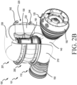
- FIGs. 2A and 2B a cross-sectional view of the engine 100 ( FIG. 2A ) and a perspective view of the engine 100 ( FIG. 2B ) from FIG. 1 are illustrated, in accordance with various embodiments.
- the engine 100 is a gas turbine engine 101.
- gas turbine engine 101 comprises a low-pressure compressor 110, a low-pressure turbine 120, and a core 130.
- the core 130 comprises a high-pressure compressor 132 and a high-pressure turbine 134.
- fluid e.g., air
- gas turbine engine 101 is depicted as a turbofan gas turbine engine herein, it should be understood that the concepts described herein are not limited to use with turbofans as the teachings may be applied to other types of turbine engines.
- a "high-pressure” compressor or turbine experiences a higher pressure than a corresponding "low-pressure” compressor or turbine.
- a "low-speed” spool operates at a lower speed than a corresponding "high-speed” spool.
- Gas turbine engine 101 comprise a low-speed spool 102 and the core 130.
- the core 130 comprises a high-speed spool 104 and/or an intermediate spool 103.
- the core 130 can be a dual spool or single spool core.
- dual spool gas turbine engines include a low-speed spool mounted concentrically with a high-speed spool (e.g., with a low-speed spool disposed within the high-speed spool).
- a sizing of the high-speed spool can be dependent on a sizing of the low-speed spool and vice versa.
- the low-speed spool 102 is mounted (e.g., via bearing systems), for rotation about central longitudinal axis A-A' and relative to an engine static structure 150. It should be understood that various bearing systems at various locations may be provided, including for example, to properly support the low-speed shaft 103.
- the shaft 105 of the core 130 is non-co-axial with the shaft 103 of the low-speed spool 102.
- the high-speed spool 104 is configured for rotation about a core longitudinal axis B-B' relative to the engine static structure 150.
- the core longitudinal axis B-B' of the high-speed spool 104 can be disposed substantially perpendicular (e.g., 90 degrees +/- 15 degrees) to the central longitudinal axis A-A'.
- the core longitudinal axis B-B' and the central longitudinal axis A-A' intersect.
- the present disclosure is not limited in this regard.
- the core-longitudinal axis B-B' and the central longitudinal axis A-A' can be offset and still be within the scope of this disclosure.
- Central longitudinal axis A-A' of the core 130 is oriented in the z direction on the provided xyz axes.
- the z direction on the provided xyz axes refers to the axial direction.
- core longitudinal axis B-B' is oriented in the y direction on the provided xyz axes (e.g., a generally radial direction relative to the central longitudinal axis A-A').
- radially refer to directions towards and away from central longitudinal axis A-A' and the z-axis or directions towards and away from core longitudinal axis B-B', respectively.
- the terms “circumferential” and “circumferentially” refer to directions about central longitudinal axis A-A' and the z-axis or about core longitudinal axis B-B' respectively.
- the low-speed spool 102 comprises a shaft 103 that interconnects the low-pressure compressor 110 and the low-pressure turbine.
- the high-speed spool 104 comprises a shaft 105 that interconnects the high-pressure compressor 132 and the high-pressure turbine 134 of the core 130.
- a combustor 136 can be located between the high-pressure compressor 132 and the high-pressure turbine 134, radially inward from the high-pressure turbine 134, or the like. The present disclosure is not limited in this regard.
- the airflow in flow-path C may be compressed by low-pressure compressor 110 and high-pressure compressor 132 of core 130, mixed and burned with fuel in combustor 136 of core 130, then expanded over high-pressure turbine 134 of core 130 and low-pressure turbine 120.
- Turbines 46, 54 rotationally drive the respective low speed spool 30 and high-speed spool 32 in response to the expansion.
- Turbines 135, 122 rotationally drive the respective low-speed spool 102 and high-speed spool 104 in response to the expansion.
- the engine 100 comprises the intercooler 200.
- intercooler 200 is configured to cool a fluid (e.g., air) traveling along flow-path C between the low-pressure compressor 110 and the high-pressure compressor 132 of the core 130.
- the intercooler 200 can be used in the gas turbine engine 101 to cool the air in the flow-path C part way through its compression cycle (e.g., between the low-pressure compressor 110 and the high-pressure compressor 132).
- the intercooler 200 is configured to reduce heat, while maintaining the pressure output. In order to be effective, it is desirable to have the intercooler 200 relatively large for the gas turbine engine 101.
- attempting to design a dual-spool gas turbine engine with concentric spools would likely be considerably large and difficult to package.
- the cooling provided by an intercooler 200 can allow for a reduced core size with improved efficiency.
- the limiting factor for core size e.g., core 130
- core 130 becomes the low-speed shaft, which in a traditional turbine engine design passes through the center of the core within the high-speed spool.
- a small core of a traditional dual spool gas turbine engine likely would not provide enough space along its axis to accommodate a large enough shaft to meet operational speed design criteria.
- a cooling system 201 with the intercooler 200 of the gas turbine engine 101 as disclosed herein provides a cooling configuration in which the core 130 is offset from the low-speed spool 102 and is oriented substantially perpendicular to the central longitudinal axis A-A' to de-couple the core 130 from the low-speed shaft 103, so that a diameter of the low-speed shaft is not restricted, in accordance with various embodiments.
- the intercooler 200 comprises an inlet duct 210, a heat exchanger 220, and an outlet duct 230.
- the inlet duct 210 extends from an outlet of the low-pressure compressor 110 to an inlet of the heat exchanger 220 and defines a flow path therein along flow-path C.
- the outlet duct 230 extends from an outlet of the heat exchanger 220 to an inlet of the high-pressure compressor 132 of the core 130 and defines a flow path therein along flow-path C.
- a shell 222 of the heat exchanger 220 defines a duct 225 configured to receive a fluid (e.g., air) traveling along the flow-path C from the low-pressure compressor 110.
- a heat transfer region 224 is defined within the duct 225.
- the heat exchanger 220 can comprise any heat transfer arrangement for a heat exchanger.
- the heat exchanger 220 can be configured as a plate heat exchanger, a double pipe heat exchangers (e.g., parallel flow, counter flow, or the like), a compact heat exchangers (e.g., unmixed flow, mixed flow, etc.), shell and tube heat exchangers, or the like.
- the present disclosure is not limited in this regard.
- air that is traveling along the flow-path C is being cooled by a fluid that is traveling through fluid conduits of the heat exchanger 220 (e.g., fluid conduits that extend through the duct 225 and are in fluid communication with the supply manifold 242 and the outlet manifold 244), and the fluid that is traveling through the fluid conduit so the heat exchanger 220 is being heated by the air that is traveling along the flow-path C.
- fluid conduits of the heat exchanger 220 e.g., fluid conduits that extend through the duct 225 and are in fluid communication with the supply manifold 242 and the outlet manifold 244
- the heat exchanger 220 has a partial annular shape as shown in FIG. 2B .
- the heat exchanger 220 is disposed radially outward from the core 130 and at least partially wrapped around the core 130.
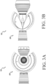
- the heat exchanger 220 defines an arc angle ⁇ (e.g., as shown in FIGs. 3A and 3B ).
- the arc angle ⁇ is greater than 90 degrees, or greater than 135 degrees, or greater than 180 degrees.
- the arc angle is between 180 degrees and 330 degrees, or between 210 degrees and 300 degrees.
- the intercooler 200 can be annular.
- outlet duct 230 would have to be de-coupled during servicing if access to the core 130 was desired.
- an envelope of the intercooler 200 can be reduced relative to a typical block-type heat exchanger.
- the core 130 can be a line replaceable unit (LRU). Stated another way, the core 130 can be replaced, without disassembling the intercooler 200, the low-pressure compressor 110, or the low-pressure turbine 120, in accordance with various embodiments. In various embodiments, by having the partial annular shape, facilitates an ease of packaging for the gas turbine engine 101. Stated another way, the partial annular shape provides an opening (e.g., between arcuate ends of the intercooler 200) for an outlet duct 140 of the core 130 to occupy to communicate the output from the core 130 to the low-pressure turbine 120.
- LRU line replaceable unit
- the intercooler 200 further comprises a supply manifold 242 and an outlet manifold 244.
- the supply manifold 242 is a distribution manifold.
- the supply manifold 242 is configured to distribute the fluid from a single conduit to a plurality of passages within the heat exchanger 220, in accordance with various embodiments.
- the outlet manifold 244 is a collection manifold.
- the outlet manifold is configured to collect the fluid from the heat exchanger after exiting the heat exchanger 220 and supply the fluid to the core 130.
- the supply manifold 242 supplies a cooling fluid (e.g., air, fuel, oil, lubricating fluid, hydraulic fluid, thermally neutral heat-transfer fluid, or any other fluid suitable for a heat exchanger) through the heat exchanger 220 and out the outlet manifold 244.
- the heat exchanger 220 defines cooling flow path D.
- the cooling flow path D comprises a serpentine shape that extends radially inward, axially, radially outward, axially, radially inward, etc.
- the flow path defined by the heat exchanger 220 is a cross-flow path to the flow path C of the partially compressed fluid from the inlet duct 210 of the intercooler.
- a "serpentine shape” as referred to herein a shape having a linear (or near linear portion), at least one bending portion, and a second linear (or near linear portion) that extends in an opposite direction to the first linear portion.
- the arrangement of the flow path D directs the flow in a substantially perpendicular direction (relative to flow path C) instead of directly counter.
- the arrangement of the flow path D provides some counter-flow effect by the multiple passes occurring in a counter direction (i.e., in an axial direction defined by longitudinal axis B-B').
- the flow path D can comprise a counter-flow path (e.g., as shown in heat exchanger 620 of FIG. 6 ). The present disclosure is not limited in this regard.
- the heat exchanger is a four-pass heat exchanger.
- a "four pass heat exchanger" refers to a heat exchanger that passes the cooling fluid in the flow path D through adjacent conduits to flow path C.
- a one pass heat exchanger, a two-pass heat exchanger, an eight-pass heat exchanger or the like are all within the scope of this disclosure.
- the supply manifold 242 extends circumferentially about the core-longitudinal axis B-B'. In various embodiments, the supply manifold 242 is spaced apart axially (i.e., along the core-longitudinal axis B-B') from the outlet manifold 244. In this regard, the outlet manifold 244 is disposed radially inward (relative to the central longitudinal axis A-A') from the supply manifold 242. In various embodiments, by having the supply manifold 242 and the outlet manifold 244 configured as such, some counter-flow effect is achieved for the intercooler 200.
- a fluid traveling along flow path D will be at its coldest near the supply manifold 242 and at its warmest near the outlet manifold 244, whereas the fluid (e.g., air) traveling along the flow path C will be at its coldest near the outlet manifold 244 and at its warmest near the supply manifold 242. Accordingly, the fluid (e.g., air) traveling along the flow path C can be more efficiently cooled by having the counter-flow configuration, in accordance with various embodiments.
- the heat exchanger 220 further comprises a shell 222.
- the shell 222 extends from the outlet of the inlet duct 210 to the inlet of the outlet duct 230 of the intercooler 200.
- the heat exchanger comprises fluid conduits that extend into the shell 222 from the supply manifold 242 and travel axially along the core longitudinal axis B-B' and/or radially in a general direction towards the inlet duct 210 and out the outlet manifold 244.
- the cooling system 201 with the intercooler 200 can either be an open system (e.g., cooling system 400 from FIG. 4A as described further herein) or a closed system (e.g., cooling system 450 from FIG. 4B ).
- the present disclosure is not limited in this regard.
- the cooling fluid can also be a fuel for the gas turbine engine 101.
- the cooling system 400 can comprise a fuel tank 310 in fluid communication with the combustor 136 through the heat exchanger 220.
- the supply manifold 242 can fluidly couple the fuel tank 410 to the heat exchanger 220, and the outlet manifold 244 can fluidly couple the heat exchanger 220 to the combustor.
- the intercooler 200 described herein may provide dual functionality for a hydrogen powered gas turbine engine (i.e., cooling a partially compressed air between a low-pressure compressor 110 and a high-pressure compressor 132 and heating a fuel from a fuel tank 410 prior to combustion in a combustor 136).
- a hydrogen powered gas turbine engine i.e., cooling a partially compressed air between a low-pressure compressor 110 and a high-pressure compressor 132 and heating a fuel from a fuel tank 410 prior to combustion in a combustor 136.
- the closed loop cooling system 450 can comprise the heat exchanger 220 and a condenser 460.
- the condenser 460 can supply the cooling fluid through the supply manifold 242, and the outlet manifold 244 can act as a return conduit that returns a heated fluid that has traveled through the heat exchanger 220 to the condenser 460 to be cooled again.
- the condenser 460 re-cools fluid that travels through the heat exchanger 220, cycles the fluid back through the heat exchanger for continuous cooling of the fluid (e.g., air) traveling through the gas turbine engine 101, in accordance with various embodiments.
- FIG. 5 perspective view of a propulsion system 500 with a first engine 510 and a second engine 520 is illustrated in accordance with various embodiments.
- the first engine 510 and the second engine 520 can both be in accordance with the engine 100 from FIGs. 2A and 2B .
- the first engine 510 is spaced apart substantially equally from the second engine 520 about a longitudinal centerline of an aircraft 10 from FIG. 1 .
- the engines 510, 520 are configured for being embedded in an aircraft (e.g., as shown in FIG. 1 ).
- the offset configuration of the core 130 relative to the low-speed spool 102 facilitates an engine configuration of a propulsion system 500 where engines 510, 520 can be disposed adjacent to one another within a fuselage 12 of an aircraft 10 from FIG. 1 because a burst disk of one core (e.g., first engine 510) would not damage the second engine 520, in accordance with various embodiments.
- the propulsion system 500 allows both low-speed spools 102 to be parallel, but the low-speed disk burst can potentially be contained or deflected as the debris would have considerably less momentum.
- references to "one embodiment,” “an embodiment,” “various embodiments,” etc. indicate that the embodiment described may include a particular feature, structure, or characteristic, but every embodiment may not necessarily include the feature, structure, or characteristic. Moreover, such phrases are not necessarily referring to the same embodiment. Further, when a particular feature, structure, or characteristic is described in connection with an embodiment, it is submitted that it is within the knowledge of one skilled in the art to affect such feature, structure, or characteristic in connection with other embodiments whether explicitly described. After reading the description, it will be apparent to one skilled in the relevant art(s) how to implement the disclosure in alternative embodiments.
Landscapes
- Engineering & Computer Science (AREA)
- Chemical & Material Sciences (AREA)
- Combustion & Propulsion (AREA)
- Mechanical Engineering (AREA)
- General Engineering & Computer Science (AREA)
- Structures Of Non-Positive Displacement Pumps (AREA)
- Heat-Exchange Devices With Radiators And Conduit Assemblies (AREA)
Applications Claiming Priority (1)
| Application Number | Priority Date | Filing Date | Title |
|---|---|---|---|
| US18/108,532 US12044171B1 (en) | 2023-02-10 | 2023-02-10 | Engine with intercooler |
Publications (2)
| Publication Number | Publication Date |
|---|---|
| EP4414546A2 true EP4414546A2 (de) | 2024-08-14 |
| EP4414546A3 EP4414546A3 (de) | 2024-10-09 |
Family
ID=89854670
Family Applications (1)
| Application Number | Title | Priority Date | Filing Date |
|---|---|---|---|
| EP24156423.6A Pending EP4414546A3 (de) | 2023-02-10 | 2024-02-07 | Motor mit zwischenkühler |
Country Status (2)
| Country | Link |
|---|---|
| US (1) | US12044171B1 (de) |
| EP (1) | EP4414546A3 (de) |
Cited By (1)
| Publication number | Priority date | Publication date | Assignee | Title |
|---|---|---|---|---|
| EP4477858A3 (de) * | 2023-06-16 | 2025-03-26 | Pratt & Whitney Canada Corp. | Zwischenkühler für turbinenmotorverdichter |
Families Citing this family (4)
| Publication number | Priority date | Publication date | Assignee | Title |
|---|---|---|---|---|
| USD1052616S1 (en) * | 2023-03-16 | 2024-11-26 | Resource Intl Inc. | Intercooler tank |
| USD1051944S1 (en) * | 2023-05-02 | 2024-11-19 | Resource Intl Inc. | Intercooler pipe |
| USD1055103S1 (en) * | 2023-06-21 | 2024-12-24 | Resource Intl Inc. | Coolant expansion tank |
| CN119616671A (zh) * | 2024-12-10 | 2025-03-14 | 南昌航空大学 | 一种超高压比紧凑型高效节能涡喷发动机 |
Family Cites Families (12)
| Publication number | Priority date | Publication date | Assignee | Title |
|---|---|---|---|---|
| US3119758A (en) * | 1962-01-30 | 1964-01-28 | Mhd Res Inc | Method and apparatus for producing acetylene |
| US5535584A (en) * | 1993-10-19 | 1996-07-16 | California Energy Commission | Performance enhanced gas turbine powerplants |
| EP0975862B1 (de) * | 1997-04-18 | 2003-01-08 | Honeywell International Inc. | Verbessertes integriertes klima- und hilfsantriebsaggregat |
| IL166089A0 (en) * | 2002-07-20 | 2006-01-15 | Idalex Technologies Inc | Evaporative duplex counterheat exchanger |
| GB2400411B (en) * | 2003-04-10 | 2006-09-06 | Rolls Royce Plc | Turbofan arrangement |
| CN100549388C (zh) * | 2005-08-22 | 2009-10-14 | 泰里迪尼技术股份有限公司 | 在高和低功率模式之间用阀调节的具有两偏轴线转轴的涡轮发动机 |
| US20090313999A1 (en) * | 2008-05-13 | 2009-12-24 | Scott Hunter | Method and apparatus for controlling fuel in a gas turbine engine |
| EP3077642B1 (de) * | 2013-12-05 | 2019-07-17 | United Technologies Corporation | Gasturbinenmotoren mit zwischenkühlern und rekuperatoren |
| US10126062B2 (en) | 2016-01-08 | 2018-11-13 | General Electric Company | Heat exchanger for embedded engine applications |
| DE102017124049B4 (de) * | 2017-10-16 | 2023-02-23 | Rolls-Royce Deutschland Ltd & Co Kg | Flugzeug mit einem Strahltriebwerk |
| US11650018B2 (en) * | 2020-02-07 | 2023-05-16 | Raytheon Technologies Corporation | Duct mounted heat exchanger |
| US11802736B2 (en) | 2020-07-29 | 2023-10-31 | Hamilton Sundstrand Corporation | Annular heat exchanger |
-
2023
- 2023-02-10 US US18/108,532 patent/US12044171B1/en active Active
-
2024
- 2024-02-07 EP EP24156423.6A patent/EP4414546A3/de active Pending
Cited By (1)
| Publication number | Priority date | Publication date | Assignee | Title |
|---|---|---|---|---|
| EP4477858A3 (de) * | 2023-06-16 | 2025-03-26 | Pratt & Whitney Canada Corp. | Zwischenkühler für turbinenmotorverdichter |
Also Published As
| Publication number | Publication date |
|---|---|
| US20240271567A1 (en) | 2024-08-15 |
| EP4414546A3 (de) | 2024-10-09 |
| US12044171B1 (en) | 2024-07-23 |
Similar Documents
| Publication | Publication Date | Title |
|---|---|---|
| US12044171B1 (en) | Engine with intercooler | |
| US11421598B2 (en) | Staggered heat exchanger array with side curtains | |
| US8763363B2 (en) | Method and system for cooling fluid in a turbine engine | |
| US11125160B2 (en) | Method and system for combination heat exchanger | |
| US9714610B2 (en) | Low profile compressor bleed air-oil coolers | |
| US12163467B2 (en) | Condenser for hydrogen steam injected turbine engine | |
| CA2936632C (en) | Integral oil tank heat exchanger | |
| CN109723558A (zh) | 包括热管理系统的燃气涡轮发动机及其操作方法 | |
| US20140202158A1 (en) | Gas turbine engine heat exchangers and methods of assembling the same | |
| US20200200040A1 (en) | Aircraft surface cooler assembly | |
| US11371786B2 (en) | Heat exchanger for a gas turbine engine | |
| US12169102B2 (en) | Plumbing with internal flow guides | |
| US6422020B1 (en) | Cast heat exchanger system for gas turbine | |
| EP4462061B1 (de) | Modularer wärmetauscher für ein flugzeugtriebwerk | |
| EP4428478B1 (de) | Wärmetauscher mit gekreuzten wärmetauscherrohren | |
| US12264627B2 (en) | Heat exchanger for a gas turbine engine | |
| EP4462058A1 (de) | Wärmetauschersysteme und vorrichtungen für erhöhte haltbarkeit | |
| US12405071B2 (en) | Heat exchanger systems and devices for reduced pressure loss | |
| US12454913B2 (en) | Gas turbine engine component with integral heat exchanger | |
| US20250146440A1 (en) | Strut microtube counterflow evaporator |
Legal Events
| Date | Code | Title | Description |
|---|---|---|---|
| PUAI | Public reference made under article 153(3) epc to a published international application that has entered the european phase |
Free format text: ORIGINAL CODE: 0009012 |
|
| STAA | Information on the status of an ep patent application or granted ep patent |
Free format text: STATUS: THE APPLICATION HAS BEEN PUBLISHED |
|
| AK | Designated contracting states |
Kind code of ref document: A2 Designated state(s): AL AT BE BG CH CY CZ DE DK EE ES FI FR GB GR HR HU IE IS IT LI LT LU LV MC ME MK MT NL NO PL PT RO RS SE SI SK SM TR |
|
| PUAL | Search report despatched |
Free format text: ORIGINAL CODE: 0009013 |
|
| AK | Designated contracting states |
Kind code of ref document: A3 Designated state(s): AL AT BE BG CH CY CZ DE DK EE ES FI FR GB GR HR HU IE IS IT LI LT LU LV MC ME MK MT NL NO PL PT RO RS SE SI SK SM TR |
|
| RIC1 | Information provided on ipc code assigned before grant |
Ipc: F02C 3/00 20060101ALI20240902BHEP Ipc: F02C 7/224 20060101ALI20240902BHEP Ipc: F02C 7/143 20060101AFI20240902BHEP |
|
| STAA | Information on the status of an ep patent application or granted ep patent |
Free format text: STATUS: REQUEST FOR EXAMINATION WAS MADE |
|
| 17P | Request for examination filed |
Effective date: 20250403 |