EP4414536A1 - Steam turbine bypass for increased water heat absorption capacity steam injected turbine engine - Google Patents
Steam turbine bypass for increased water heat absorption capacity steam injected turbine engine Download PDFInfo
- Publication number
- EP4414536A1 EP4414536A1 EP23215255.3A EP23215255A EP4414536A1 EP 4414536 A1 EP4414536 A1 EP 4414536A1 EP 23215255 A EP23215255 A EP 23215255A EP 4414536 A1 EP4414536 A1 EP 4414536A1
- Authority
- EP
- European Patent Office
- Prior art keywords
- flow
- steam
- turbine
- engine
- steam flow
- Prior art date
- Legal status (The legal status is an assumption and is not a legal conclusion. Google has not performed a legal analysis and makes no representation as to the accuracy of the status listed.)
- Granted
Links
Images

Classifications
-
- F—MECHANICAL ENGINEERING; LIGHTING; HEATING; WEAPONS; BLASTING
- F02—COMBUSTION ENGINES; HOT-GAS OR COMBUSTION-PRODUCT ENGINE PLANTS
- F02C—GAS-TURBINE PLANTS; AIR INTAKES FOR JET-PROPULSION PLANTS; CONTROLLING FUEL SUPPLY IN AIR-BREATHING JET-PROPULSION PLANTS
- F02C3/00—Gas-turbine plants characterised by the use of combustion products as the working fluid
- F02C3/20—Gas-turbine plants characterised by the use of combustion products as the working fluid using a special fuel, oxidant, or dilution fluid to generate the combustion products
- F02C3/30—Adding water, steam or other fluids for influencing combustion, e.g. to obtain cleaner exhaust gases
- F02C3/305—Increasing the power, speed, torque or efficiency of a gas turbine or the thrust of a turbojet engine by injecting or adding water, steam or other fluids
-
- B—PERFORMING OPERATIONS; TRANSPORTING
- B64—AIRCRAFT; AVIATION; COSMONAUTICS
- B64D—EQUIPMENT FOR FITTING IN OR TO AIRCRAFT; FLIGHT SUITS; PARACHUTES; ARRANGEMENT OR MOUNTING OF POWER PLANTS OR PROPULSION TRANSMISSIONS IN AIRCRAFT
- B64D27/00—Arrangement or mounting of power plants in aircraft; Aircraft characterised by the type or position of power plants
- B64D27/02—Aircraft characterised by the type or position of power plants
- B64D27/026—Aircraft characterised by the type or position of power plants comprising different types of power plants, e.g. combination of a piston engine and a gas-turbine
-
- B—PERFORMING OPERATIONS; TRANSPORTING
- B64—AIRCRAFT; AVIATION; COSMONAUTICS
- B64D—EQUIPMENT FOR FITTING IN OR TO AIRCRAFT; FLIGHT SUITS; PARACHUTES; ARRANGEMENT OR MOUNTING OF POWER PLANTS OR PROPULSION TRANSMISSIONS IN AIRCRAFT
- B64D27/00—Arrangement or mounting of power plants in aircraft; Aircraft characterised by the type or position of power plants
- B64D27/02—Aircraft characterised by the type or position of power plants
- B64D27/24—Aircraft characterised by the type or position of power plants using steam or spring force
-
- F—MECHANICAL ENGINEERING; LIGHTING; HEATING; WEAPONS; BLASTING
- F01—MACHINES OR ENGINES IN GENERAL; ENGINE PLANTS IN GENERAL; STEAM ENGINES
- F01D—NON-POSITIVE DISPLACEMENT MACHINES OR ENGINES, e.g. STEAM TURBINES
- F01D13/00—Combinations of two or more machines or engines
- F01D13/02—Working-fluid interconnection of machines or engines
-
- F—MECHANICAL ENGINEERING; LIGHTING; HEATING; WEAPONS; BLASTING
- F01—MACHINES OR ENGINES IN GENERAL; ENGINE PLANTS IN GENERAL; STEAM ENGINES
- F01D—NON-POSITIVE DISPLACEMENT MACHINES OR ENGINES, e.g. STEAM TURBINES
- F01D17/00—Regulating or controlling by varying flow
- F01D17/02—Arrangement of sensing elements
- F01D17/08—Arrangement of sensing elements responsive to condition of working-fluid, e.g. pressure
-
- F—MECHANICAL ENGINEERING; LIGHTING; HEATING; WEAPONS; BLASTING
- F01—MACHINES OR ENGINES IN GENERAL; ENGINE PLANTS IN GENERAL; STEAM ENGINES
- F01D—NON-POSITIVE DISPLACEMENT MACHINES OR ENGINES, e.g. STEAM TURBINES
- F01D17/00—Regulating or controlling by varying flow
- F01D17/02—Arrangement of sensing elements
- F01D17/08—Arrangement of sensing elements responsive to condition of working-fluid, e.g. pressure
- F01D17/085—Arrangement of sensing elements responsive to condition of working-fluid, e.g. pressure to temperature
-
- F—MECHANICAL ENGINEERING; LIGHTING; HEATING; WEAPONS; BLASTING
- F01—MACHINES OR ENGINES IN GENERAL; ENGINE PLANTS IN GENERAL; STEAM ENGINES
- F01D—NON-POSITIVE DISPLACEMENT MACHINES OR ENGINES, e.g. STEAM TURBINES
- F01D17/00—Regulating or controlling by varying flow
- F01D17/10—Final actuators
- F01D17/105—Final actuators by passing part of the fluid
-
- F—MECHANICAL ENGINEERING; LIGHTING; HEATING; WEAPONS; BLASTING
- F01—MACHINES OR ENGINES IN GENERAL; ENGINE PLANTS IN GENERAL; STEAM ENGINES
- F01D—NON-POSITIVE DISPLACEMENT MACHINES OR ENGINES, e.g. STEAM TURBINES
- F01D17/00—Regulating or controlling by varying flow
- F01D17/10—Final actuators
- F01D17/12—Final actuators arranged in stator parts
- F01D17/14—Final actuators arranged in stator parts varying effective cross-sectional area of nozzles or guide conduits
- F01D17/141—Final actuators arranged in stator parts varying effective cross-sectional area of nozzles or guide conduits by means of shiftable members or valves obturating part of the flow path
- F01D17/145—Final actuators arranged in stator parts varying effective cross-sectional area of nozzles or guide conduits by means of shiftable members or valves obturating part of the flow path by means of valves, e.g. for steam turbines
-
- F—MECHANICAL ENGINEERING; LIGHTING; HEATING; WEAPONS; BLASTING
- F01—MACHINES OR ENGINES IN GENERAL; ENGINE PLANTS IN GENERAL; STEAM ENGINES
- F01D—NON-POSITIVE DISPLACEMENT MACHINES OR ENGINES, e.g. STEAM TURBINES
- F01D25/00—Component parts, details, or accessories, not provided for in, or of interest apart from, other groups
- F01D25/32—Collecting of condensation water; Drainage ; Removing solid particles
-
- F—MECHANICAL ENGINEERING; LIGHTING; HEATING; WEAPONS; BLASTING
- F01—MACHINES OR ENGINES IN GENERAL; ENGINE PLANTS IN GENERAL; STEAM ENGINES
- F01K—STEAM ENGINE PLANTS; STEAM ACCUMULATORS; ENGINE PLANTS NOT OTHERWISE PROVIDED FOR; ENGINES USING SPECIAL WORKING FLUIDS OR CYCLES
- F01K15/00—Adaptations of plants for special use
- F01K15/02—Adaptations of plants for special use for driving vehicles, e.g. locomotives
-
- F—MECHANICAL ENGINEERING; LIGHTING; HEATING; WEAPONS; BLASTING
- F01—MACHINES OR ENGINES IN GENERAL; ENGINE PLANTS IN GENERAL; STEAM ENGINES
- F01K—STEAM ENGINE PLANTS; STEAM ACCUMULATORS; ENGINE PLANTS NOT OTHERWISE PROVIDED FOR; ENGINES USING SPECIAL WORKING FLUIDS OR CYCLES
- F01K17/00—Using steam or condensate extracted or exhausted from steam engine plant
- F01K17/02—Using steam or condensate extracted or exhausted from steam engine plant for heating purposes, e.g. industrial, domestic
- F01K17/025—Using steam or condensate extracted or exhausted from steam engine plant for heating purposes, e.g. industrial, domestic in combination with at least one gas turbine, e.g. a combustion gas turbine
-
- F—MECHANICAL ENGINEERING; LIGHTING; HEATING; WEAPONS; BLASTING
- F01—MACHINES OR ENGINES IN GENERAL; ENGINE PLANTS IN GENERAL; STEAM ENGINES
- F01K—STEAM ENGINE PLANTS; STEAM ACCUMULATORS; ENGINE PLANTS NOT OTHERWISE PROVIDED FOR; ENGINES USING SPECIAL WORKING FLUIDS OR CYCLES
- F01K21/00—Steam engine plants not otherwise provided for
- F01K21/04—Steam engine plants not otherwise provided for using mixtures of steam and gas; Plants generating or heating steam by bringing water or steam into direct contact with hot gas
- F01K21/047—Steam engine plants not otherwise provided for using mixtures of steam and gas; Plants generating or heating steam by bringing water or steam into direct contact with hot gas having at least one combustion gas turbine
-
- F—MECHANICAL ENGINEERING; LIGHTING; HEATING; WEAPONS; BLASTING
- F01—MACHINES OR ENGINES IN GENERAL; ENGINE PLANTS IN GENERAL; STEAM ENGINES
- F01K—STEAM ENGINE PLANTS; STEAM ACCUMULATORS; ENGINE PLANTS NOT OTHERWISE PROVIDED FOR; ENGINES USING SPECIAL WORKING FLUIDS OR CYCLES
- F01K23/00—Plants characterised by more than one engine delivering power external to the plant, the engines being driven by different fluids
- F01K23/02—Plants characterised by more than one engine delivering power external to the plant, the engines being driven by different fluids the engine cycles being thermally coupled
- F01K23/06—Plants characterised by more than one engine delivering power external to the plant, the engines being driven by different fluids the engine cycles being thermally coupled combustion heat from one cycle heating the fluid in another cycle
- F01K23/10—Plants characterised by more than one engine delivering power external to the plant, the engines being driven by different fluids the engine cycles being thermally coupled combustion heat from one cycle heating the fluid in another cycle with exhaust fluid of one cycle heating the fluid in another cycle
-
- F—MECHANICAL ENGINEERING; LIGHTING; HEATING; WEAPONS; BLASTING
- F01—MACHINES OR ENGINES IN GENERAL; ENGINE PLANTS IN GENERAL; STEAM ENGINES
- F01K—STEAM ENGINE PLANTS; STEAM ACCUMULATORS; ENGINE PLANTS NOT OTHERWISE PROVIDED FOR; ENGINES USING SPECIAL WORKING FLUIDS OR CYCLES
- F01K23/00—Plants characterised by more than one engine delivering power external to the plant, the engines being driven by different fluids
- F01K23/12—Plants characterised by more than one engine delivering power external to the plant, the engines being driven by different fluids the engines being mechanically coupled
- F01K23/16—Plants characterised by more than one engine delivering power external to the plant, the engines being driven by different fluids the engines being mechanically coupled all the engines being turbines
-
- F—MECHANICAL ENGINEERING; LIGHTING; HEATING; WEAPONS; BLASTING
- F02—COMBUSTION ENGINES; HOT-GAS OR COMBUSTION-PRODUCT ENGINE PLANTS
- F02C—GAS-TURBINE PLANTS; AIR INTAKES FOR JET-PROPULSION PLANTS; CONTROLLING FUEL SUPPLY IN AIR-BREATHING JET-PROPULSION PLANTS
- F02C6/00—Plural gas-turbine plants; Combinations of gas-turbine plants with other apparatus; Adaptations of gas-turbine plants for special use
- F02C6/18—Plural gas-turbine plants; Combinations of gas-turbine plants with other apparatus; Adaptations of gas-turbine plants for special use using the waste heat of gas-turbine plants outside the plants themselves, e.g. gas-turbine power heat plants
-
- G—PHYSICS
- G01—MEASURING; TESTING
- G01N—INVESTIGATING OR ANALYSING MATERIALS BY DETERMINING THEIR CHEMICAL OR PHYSICAL PROPERTIES
- G01N25/00—Investigating or analyzing materials by the use of thermal means
- G01N25/56—Investigating or analyzing materials by the use of thermal means by investigating moisture content
- G01N25/58—Investigating or analyzing materials by the use of thermal means by investigating moisture content by measuring changes of properties of the material due to heat, cold or expansion
- G01N25/60—Investigating or analyzing materials by the use of thermal means by investigating moisture content by measuring changes of properties of the material due to heat, cold or expansion for determining the wetness of steam
-
- F—MECHANICAL ENGINEERING; LIGHTING; HEATING; WEAPONS; BLASTING
- F05—INDEXING SCHEMES RELATING TO ENGINES OR PUMPS IN VARIOUS SUBCLASSES OF CLASSES F01-F04
- F05D—INDEXING SCHEME FOR ASPECTS RELATING TO NON-POSITIVE-DISPLACEMENT MACHINES OR ENGINES, GAS-TURBINES OR JET-PROPULSION PLANTS
- F05D2220/00—Application
- F05D2220/30—Application in turbines
- F05D2220/32—Application in turbines in gas turbines
- F05D2220/323—Application in turbines in gas turbines for aircraft propulsion, e.g. jet engines
-
- F—MECHANICAL ENGINEERING; LIGHTING; HEATING; WEAPONS; BLASTING
- F05—INDEXING SCHEMES RELATING TO ENGINES OR PUMPS IN VARIOUS SUBCLASSES OF CLASSES F01-F04
- F05D—INDEXING SCHEME FOR ASPECTS RELATING TO NON-POSITIVE-DISPLACEMENT MACHINES OR ENGINES, GAS-TURBINES OR JET-PROPULSION PLANTS
- F05D2220/00—Application
- F05D2220/70—Application in combination with
- F05D2220/72—Application in combination with a steam turbine
-
- F—MECHANICAL ENGINEERING; LIGHTING; HEATING; WEAPONS; BLASTING
- F05—INDEXING SCHEMES RELATING TO ENGINES OR PUMPS IN VARIOUS SUBCLASSES OF CLASSES F01-F04
- F05D—INDEXING SCHEME FOR ASPECTS RELATING TO NON-POSITIVE-DISPLACEMENT MACHINES OR ENGINES, GAS-TURBINES OR JET-PROPULSION PLANTS
- F05D2220/00—Application
- F05D2220/70—Application in combination with
- F05D2220/74—Application in combination with a gas turbine
-
- Y—GENERAL TAGGING OF NEW TECHNOLOGICAL DEVELOPMENTS; GENERAL TAGGING OF CROSS-SECTIONAL TECHNOLOGIES SPANNING OVER SEVERAL SECTIONS OF THE IPC; TECHNICAL SUBJECTS COVERED BY FORMER USPC CROSS-REFERENCE ART COLLECTIONS [XRACs] AND DIGESTS
- Y02—TECHNOLOGIES OR APPLICATIONS FOR MITIGATION OR ADAPTATION AGAINST CLIMATE CHANGE
- Y02E—REDUCTION OF GREENHOUSE GAS [GHG] EMISSIONS, RELATED TO ENERGY GENERATION, TRANSMISSION OR DISTRIBUTION
- Y02E20/00—Combustion technologies with mitigation potential
- Y02E20/16—Combined cycle power plant [CCPP], or combined cycle gas turbine [CCGT]
-
- Y—GENERAL TAGGING OF NEW TECHNOLOGICAL DEVELOPMENTS; GENERAL TAGGING OF CROSS-SECTIONAL TECHNOLOGIES SPANNING OVER SEVERAL SECTIONS OF THE IPC; TECHNICAL SUBJECTS COVERED BY FORMER USPC CROSS-REFERENCE ART COLLECTIONS [XRACs] AND DIGESTS
- Y02—TECHNOLOGIES OR APPLICATIONS FOR MITIGATION OR ADAPTATION AGAINST CLIMATE CHANGE
- Y02T—CLIMATE CHANGE MITIGATION TECHNOLOGIES RELATED TO TRANSPORTATION
- Y02T50/00—Aeronautics or air transport
- Y02T50/50—On board measures aiming to increase energy efficiency
-
- Y—GENERAL TAGGING OF NEW TECHNOLOGICAL DEVELOPMENTS; GENERAL TAGGING OF CROSS-SECTIONAL TECHNOLOGIES SPANNING OVER SEVERAL SECTIONS OF THE IPC; TECHNICAL SUBJECTS COVERED BY FORMER USPC CROSS-REFERENCE ART COLLECTIONS [XRACs] AND DIGESTS
- Y02—TECHNOLOGIES OR APPLICATIONS FOR MITIGATION OR ADAPTATION AGAINST CLIMATE CHANGE
- Y02T—CLIMATE CHANGE MITIGATION TECHNOLOGIES RELATED TO TRANSPORTATION
- Y02T50/00—Aeronautics or air transport
- Y02T50/60—Efficient propulsion technologies, e.g. for aircraft
- Y02T50/678—Aviation using fuels of non-fossil origin
Definitions
- the present disclosure relates generally to a steam injected turbine engine and more particularly to a steam injection system that increases a heat absorption capacity of an extracted water flow and a bypass passage for controlling condensation accumulation.
- Turbine engines compress incoming core airflow, mix the compressed airflow with fuel that is ignited in a combustor to generate a high energy exhaust gas flow. Some energy in the high energy exhaust flow is recovered as it is expanded through a turbine section. Water can be extracted from the exhaust gas flow and transformed into a steam flow and injected into the core flow to enhance engine efficiency. Additionally, the recovered water flow can be utilized to absorb and recover heat from the exhaust gas flow. The recovered heat can be used to generate mechanical power in a steam turbine. The amount of heat available may not always be sufficient to generate a steam flow to drive the steam turbine. Moreover, condensation accumulation may reduce gains in efficiency provided by recovered heat.
- Turbine engine manufacturers continue to seek further improvements to engine performance including improvements to reduce environmental impact while improving thermal and propulsive efficiencies.
- a turbine engine assembly includes, among other possible things, a core engine that generates an exhaust gas flow, a condenser where water is extracted from the exhaust gas flow, an evaporator where heat is input into the water that is extracted by the condenser to generate a first steam flow, a first steam turbine where the first steam flow is expanded and cooled to generate a first cooled flow, a bypass passage that defines a path for the first steam flow around the first steam turbine, and a superheater where at least one of the first steam flow and the first cooled flow is reheated to generate a second steam flow.
- the turbine engine includes a valve that regulates flow through the bypass passage and a controller that is programmed to operate the valve to route the first heated flow around the first steam turbine at a takeoff engine operating condition.
- the turbine engine includes a valve that regulates flow through the bypass passage and a controller that is programmed to operate the valve to route the first heated flow around the first steam turbine in response to a steam quality that begins to fall below a predefined amount.
- the turbine engine includes a second steam turbine where a steam flow from the superheater is expanded to generate shaft power.
- At least one of the first steam turbine and the second steam turbine is mechanically coupled to an engine spool.
- the core engine includes a core flow path and at least one of the first steam flow and the second steam flow is injected into the core flow path.
- the turbine engine assembly includes a pump where water extracted from the condenser is pressurized before being communicated to the first evaporator.
- a pressure of water at the first evaporator is greater than a pressure of water at the superheater.
- the first evaporator and the superheater are disposed within a flow path for the exhaust gas flow.
- the first evaporator receives the exhaust gas flow after the superheater.
- the turbine engine assembly includes a fuel system where a hydrogen based fuel flow is communicated to a combustor of the core engine.
- An aircraft propulsion system includes, among other possible things, a core engine assembly that includes a compressor where an inlet airflow is compressed and communicated to a combustor where a compressed core flow is mixed with fuel and ignited to generate an exhaust gas flow that is expanded through a turbine section to generate shaft power, a hydrogen based fuel system for supplying a hydrogen based fuel to the combustor, a condenser where water is extracted from the exhaust gas flow, a first evaporator where heat is input into the water that is extracted by the condenser to generate a first steam flow, a first steam turbine where the first steam flow is expanded and cooled to generate a first cooled flow, a superheater where at least one of the first steam flow and the first cooled flow is reheated to generate a second steam flow, a bypass passage that defines a path for first steam flow around the first steam turbine to the superheater, a second steam turbine where the second steam flow from the superheater is expanded and cooled,
- the predefined engine operating condition includes a takeoff engine operating condition.
- the predefined engine operating condition includes a steam quality below predefined value.
- the core engine includes a core flow path and the second steam flow is injected into the core flow path.
- a method of operating a steam injected turbine engine includes, among other possible things, transforming a water flow into a first steam flow with a first heat input, determining a condition of the first steam flow, bypassing the first steam flow around a first steam turbine to a second heat input in response to the determined condition of the first steam flow being indicative of condensation greater than a predefined amount, generating a second steam flow with the second heat input, and injecting the second steam flow into a core flow path of a core engine.
- the method further includes expanding the first steam flow through a first steam turbine to cool the first steam flow in response to the determined condition of the first steam flow being indicative of a condensation below the predefined amount followed by reheating with the second heat input to generate the second steam flow.
- the method includes operating a valve to route the first steam flow through a bypass in response to the determined condition of the first steam flow.
- the first heat input is from an exhaust gas flow in a first evaporator and the second heat input is from the exhaust gas flow in a superheater.
- the method includes pressurizing the water flow before transformation into the first steam flow.
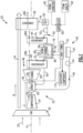
- Figure 1 schematically illustrates an engine assembly 20 where steam is injected into the core flow path C to increase mass flow through a turbine section 28 and thereby provide increased power without additional work from a compressor section 24.
- Water for generating the steam is recovered from the exhaust gas flow. The water is further utilized to recover thermal energy from the exhaust gas flow 38.
- a steam turbine 68 provides a means of increasing the heat absorption capacity of the recovered water without a corresponding increase in the amount of water recovered from the exhaust gas flow 38.
- Condensation can accumulate during certain engine operating conditions due to insufficient heat availability. Moreover, during some engine operating conditions, an initial heat input may not be sufficient to generate a steam flow of desired quality for use in the steam turbine.
- the disclosed engine assembly includes a bypass passage for routing an initial steam flow around the steam turbine for further heating prior to injection into the core flow path C. Selective routing of a steam flow around the steam turbine at select operating conditions can control condensation accumulation and increase engine efficiencies.
- the engine assembly 20 includes a core engine 22 with a fan 30, the compressor section 24, a combustor section 26 and the turbine section 28 disposed serially along an engine axis A.
- the compressor section 24 is coupled to the turbine section 28 by a shaft 94 to define an engine spool 96.
- the fan 30 drives inlet airflow 32 into a bypass flow path B and a core flow path C.
- a core flow 36 is compressed and communicated to the combustor section 26.
- compressed core airflow 36 is mixed with a fuel flow 46 and ignited to generate the high energy combusted exhaust gas flow 38 that is expanded through the turbine section 28 to extract energy to drive the compressor section 24 and the fan 30.
- a steam flow 60 is injected into the core flow 36 and increases mass flow through the turbine section 28 and thereby increases engine power and efficiency.
- the increased engine power is due to an increasing mass flow through the turbine section 28 without a corresponding increase in work from the compressor section 24.
- a fuel system 40 includes a fuel tank 42 and a fuel pump 44 for generating the fuel flow 46.
- the example fuel system 40 is configured to provide a hydrogen based fuel such as liquid hydrogen (LH 2 ).
- LH 2 liquid hydrogen
- hydrogen is disclosed by way of example, other non-carbon based fuels could be utilized and are within the contemplation of this disclosure.
- the disclosed features may also be beneficial in an engine configured to operate with traditional hydrocarbon based fuels.
- Energy from the exhaust gas flow 38 is recovered as heat input into water recovered by a condenser 48.
- a water flow 54 from the condenser 48 is communicated at or near ambient pressures to a water tank 50.
- a pump 52 communicates a pressurized water flow 56 to a first evaporator 64.
- the pressurized water flow 56 is of high pressure in the range of between 1500 PSI (10342 kPa) and 5000 PSI (34474 kPa).
- the pressurize water flow 56 is communicated to the first evaporator 64 at a pressure of about 2000 PSI (13790 kPa).
- the first evaporator 64 inputs a first amount of heat, Q1, into the pressurized water flow 56 to generate a first steam flow 58. If the first steam flow 58 is of a sufficient quality it can be routed to a first steam turbine 68 to generate shaft power 70. Expansion through the steam turbine 68 cools the first steam flow 58 and generates a cooled steam flow 62 that is exhausted from the steam turbine 68.
- the cooled steam flow 62 has an increased capacity to absorb heat as compared to the first steam flow 58.
- the cooled steam flow 62 is also at a lower pressure and communicated to a superheater 66.
- the superheater 66 is closer to the turbine section 28 than the first evaporator 64 and is therefore exposed to a higher temperature exhaust gas flow 38A as compared to the exhaust gas flow 38B that is communicated downstream to the first evaporator 64.
- Expansion through the steam turbine 68 reduces the pressure of the cooled flow 62 and the pressures within the superheater 66.
- a second heat input, Q2, into the cooled flow 62 produces a second steam flow 60 that is injected into the core flow 36.
- the second steam flow 60 is injected into the core flow 36 at the combustor 26.
- the second steam flow 60 may be injected upstream of the combustor 26 or other locations within the core flow path C.
- the steam turbine 68 generates the shaft power 70 that can be used to drive engine and/or aircraft accessory components 110.
- the shaft power 70 may also be coupled to the engine spool 96 for providing additional power for engine operation.
- a single steam turbine 68 is disclosed by way of example, several steam turbines could be utilized and receive the first steam flow 58 and emit a cooled and lower pressure cooled flow 62.
- the first heat input Q1 is not sufficient to generate steam of a desired quality.
- expansion through the steam turbine 68 may produce cooled flow 62 of insufficient quality such that the steam turbine 68 is subject to erosion and other issues.
- Steam quality is a value indicative of a ratio of vapor to liquid in a steam flow. A steam quality of 100% indicates all vapor. A steam quality of 95% indicates 95% vapor and 5% liquid. The more liquid in the steam flow, the greater chance for an undesired accumulation of condensation. Moreover, steam of a lower quality may not have sufficient energy to drive the steam turbine as desired.
- the steam quality may be indicative of insufficient heat presence in the exhaust gas flow portion 38B within the first evaporator 64. Heat may be insufficient due to engine operating conditions, such as during idling and engine takeoff operations. The inlet and outlet of the steam turbine 68 can become saturated with condensation if engine conditions and heat input is not sufficient.
- the example engine 20 includes a bypass passage 76 to route the first steam flow 58 around the first steam turbine 68 in response to a predefined set of engine operating conditions.
- the predefined engine operating conditions may include, among other possible things, one or more temperatures, pressures, power settings and/or any other engine condition indicative of insufficient heat to produce heat of a desired quality.
- a valve 78 is provided in the bypass passage 76 and is operated by a controller 80.
- the controller 80 is programmed to actuate the valve 78 to control a bypass flow 86 based on information indicative of an engine operating condition as schematically shown at 82 and/or steam quality, schematically shown at 84.
- the controller 80 is programmed to open the bypass passage 76 during takeoff operations.
- the controller 80 is programmed to close the valve 78 and force flow through the first steam turbine 68 during cruise conditions.
- the controller 80 is programmed to open the valve 78 to bypass flow around the first steam turbine 68 based on information indicative of steam quality 84.
- the steam quality 84 may be determined by measurements indicative of pressure and temperatures of the first steam flow 58 and may be descriptive of the steam quality entering the steam turbine 68 or may be descriptive of the steam quality that would exit the steam turbine 68 without being bypassed.
- the steam quality 84 may also be determined based on other engine operating conditions that are indicative of a certain range of steam quality.
- the controller 80 is programmed to open the valve 78 to bypass flow around the first steam turbine in response to indications that a steam quality is below 85%.
- the threshold for bypassing flow is a steam quality that is less than about 90% at the turbine exit.
- the controller 80 may be programmed to operate utilizing a predictive model of steam quality at an exit of the steam turbine 68.
- the controller 80 may utilized the predictive model to predict a steam quality at the exit of the steam turbine 68 based on inlet temperature and pressure of the system without an open bypass. Once the predicted steam quality reaches a predefined predicted steam quality the bypass valve 78 can be closed to direct steam through the steam turbine 68.
- the example controller 80 relates to a device and system for performing necessary computing or calculation operations.
- This system may be specially constructed for this purpose, or it may comprise a portion of an overall engine controller selectively activated or reconfigured by a computer program stored in the computer.
- the computer program and also data required for its execution may be stored in a computer readable storage medium, such as, but is not limited to, any type of disk including floppy disks, optical disks, CD-ROMs, magnetic-optical disks, readonly memories (ROMs), random access memories (RAMS), EPROMs, EEPROMs, magnetic or optical cards, application specific integrated circuits (ASICs), or any type of media suitable for storing electronic instructions.
- the example engine assembly 20 is shown with a second steam turbine 72 that is downstream of the superheater 66.
- the second steam turbine 72 receives the second steam flow 60 that has been exposed to a second heat input Q2 in the superheater.
- the second steam turbine 72 may generate shaft power 74 to drive engine accessory components.
- the second heat input Q2 is of higher temperature due to the closer proximity to the exit of the turbine section 28.
- a second bypass passage 88 is provided to route steam flow around the second steam turbine 72.
- a valve 90 is actuated by the controller 80 based on engine operating conditions, steam quality and/or other criteria that provides for improved engine power and efficiency.
- the second bypass passage 88 provides for a steam flow to be communicated directly to the combustor 26 without first driving the second steam turbine 72.
- first and second steam turbines 68, 72 are disclosed by way of example, additional steam turbines could be included with or without bypass passages to provide for tailoring of engine operations based on steam quality, engine operation and any other engine or aircraft operating parameters.
- water 54 is extracted from a portion of the exhaust gas flow 38C in communication with the condenser 48.
- the exhaust gas flow portion 38C passing through the condenser 48 has rejected some heat in the first and second heat exchangers 64, 66. Accordingly, the exhaust gas flow portion 38C is cooler than it would be upstream of the condenser 48.
- a cooling flow cools the exhaust gas flow portion 38C to condense water 54.
- the bypass airflow 34 provides cooling as a heat sink for the condenser 48. Other cooling flows could be utilized and are within the scope and contemplation of this disclosure.
- the recovered water 54 is pressurized by a pump 52 to a pressure of about 2000 PSI (13790 kPa) and communicated to the first evaporator 64.
- the first heat input Q1 from the exhaust gas flow portion 38B in the first evaporator 64 is absorbed by the pressurized water flow 56 to generate the first steam flow 58.
- Other heat sources may also input heat into the pressurized water flow 56 and are within the contemplation and scope of this disclosure.
- the first steam flow 58 is of a sufficient steam quality, for example above 90%, it is communicated to the first steam turbine 68 to generate shaft power 70 and to provide a cooled flow 62. Moreover, if the engine is operating at a predefined condition, such as for example a cruise operating condition, the first steam flow 58 would be communicated to the first steam turbine 68. Although some example some example criteria for passing steam to the first steam turbine are disclosed, other criteria may be used and are within the scope and contemplation of this disclosure.
- the valve 78 will be opened to open the bypass passage 76.
- the bypass flow 86 is routed to the superheater 66 and further heated by the second heat input Q2.
- the second heat input Q2 is hotter than the first heat input Q 1 due to the closer proximity to the turbine section 28.
- a second steam flow 60 is generated and communicated to the combustor 26.
- first steam flow 58 is expanded through the first steam turbine 68
- shaft power 70 is generated and utilized to drive accessory components.
- the expansion of the first steam flow 58 though the first steam turbine 68 increases the capacity for heat absorption to improve engine efficiency.
- the bypass passage 76 enables tailoring the use of steam to engine operating conditions to maintain engine efficiency gains and prevent condensation accumulation.
Landscapes
- Engineering & Computer Science (AREA)
- Mechanical Engineering (AREA)
- General Engineering & Computer Science (AREA)
- Chemical & Material Sciences (AREA)
- Combustion & Propulsion (AREA)
- Aviation & Aerospace Engineering (AREA)
- Biochemistry (AREA)
- Analytical Chemistry (AREA)
- Life Sciences & Earth Sciences (AREA)
- General Health & Medical Sciences (AREA)
- General Physics & Mathematics (AREA)
- Immunology (AREA)
- Pathology (AREA)
- Health & Medical Sciences (AREA)
- Physics & Mathematics (AREA)
- Engine Equipment That Uses Special Cycles (AREA)
- Control Of Turbines (AREA)
Abstract
Description
- The present disclosure relates generally to a steam injected turbine engine and more particularly to a steam injection system that increases a heat absorption capacity of an extracted water flow and a bypass passage for controlling condensation accumulation.
- Reduction and/or elimination of carbon emissions generated by aircraft operation is a stated goal of aircraft manufacturers and airline operators. Turbine engines compress incoming core airflow, mix the compressed airflow with fuel that is ignited in a combustor to generate a high energy exhaust gas flow. Some energy in the high energy exhaust flow is recovered as it is expanded through a turbine section. Water can be extracted from the exhaust gas flow and transformed into a steam flow and injected into the core flow to enhance engine efficiency. Additionally, the recovered water flow can be utilized to absorb and recover heat from the exhaust gas flow. The recovered heat can be used to generate mechanical power in a steam turbine. The amount of heat available may not always be sufficient to generate a steam flow to drive the steam turbine. Moreover, condensation accumulation may reduce gains in efficiency provided by recovered heat.
- Turbine engine manufacturers continue to seek further improvements to engine performance including improvements to reduce environmental impact while improving thermal and propulsive efficiencies.
- A turbine engine assembly according to an example disclosed embodiment, includes, among other possible things, a core engine that generates an exhaust gas flow, a condenser where water is extracted from the exhaust gas flow, an evaporator where heat is input into the water that is extracted by the condenser to generate a first steam flow, a first steam turbine where the first steam flow is expanded and cooled to generate a first cooled flow, a bypass passage that defines a path for the first steam flow around the first steam turbine, and a superheater where at least one of the first steam flow and the first cooled flow is reheated to generate a second steam flow.
- In a further embodiment of the foregoing, the turbine engine includes a valve that regulates flow through the bypass passage and a controller that is programmed to operate the valve to route the first heated flow around the first steam turbine at a takeoff engine operating condition.
- In a further embodiment of any of the foregoing, the turbine engine includes a valve that regulates flow through the bypass passage and a controller that is programmed to operate the valve to route the first heated flow around the first steam turbine in response to a steam quality that begins to fall below a predefined amount.
- In a further embodiment of any of the foregoing, the turbine engine includes a second steam turbine where a steam flow from the superheater is expanded to generate shaft power.
- In a further embodiment of any of the foregoing, at least one of the first steam turbine and the second steam turbine is mechanically coupled to an engine spool.
- In a further embodiment of any of the foregoing, the core engine includes a core flow path and at least one of the first steam flow and the second steam flow is injected into the core flow path.
- In a further embodiment of any of the foregoing, the turbine engine assembly includes a pump where water extracted from the condenser is pressurized before being communicated to the first evaporator.
- In a further embodiment of any of the foregoing, a pressure of water at the first evaporator is greater than a pressure of water at the superheater.
- In a further embodiment of any of the foregoing, the first evaporator and the superheater are disposed within a flow path for the exhaust gas flow.
- In a further embodiment of any of the foregoing, the first evaporator receives the exhaust gas flow after the superheater.
- In a further embodiment of any of the foregoing, the turbine engine assembly includes a fuel system where a hydrogen based fuel flow is communicated to a combustor of the core engine.
- An aircraft propulsion system according to another example disclosed embodiment, includes, among other possible things, a core engine assembly that includes a compressor where an inlet airflow is compressed and communicated to a combustor where a compressed core flow is mixed with fuel and ignited to generate an exhaust gas flow that is expanded through a turbine section to generate shaft power, a hydrogen based fuel system for supplying a hydrogen based fuel to the combustor, a condenser where water is extracted from the exhaust gas flow, a first evaporator where heat is input into the water that is extracted by the condenser to generate a first steam flow, a first steam turbine where the first steam flow is expanded and cooled to generate a first cooled flow, a superheater where at least one of the first steam flow and the first cooled flow is reheated to generate a second steam flow, a bypass passage that defines a path for first steam flow around the first steam turbine to the superheater, a second steam turbine where the second steam flow from the superheater is expanded and cooled, a valve that regulates flow through the bypass passage, and a controller that is programmed to operate the valve to route the first steam flow around the first steam turbine in response to a predefined engine operation condition.
- In a further embodiment of the foregoing, the predefined engine operating condition includes a takeoff engine operating condition.
- In a further embodiment of any of the foregoing, the predefined engine operating condition includes a steam quality below predefined value.
- In a further embodiment of any of the foregoing, the core engine includes a core flow path and the second steam flow is injected into the core flow path.
- A method of operating a steam injected turbine engine according to another example disclosed embodiment, includes, among other possible things, transforming a water flow into a first steam flow with a first heat input, determining a condition of the first steam flow, bypassing the first steam flow around a first steam turbine to a second heat input in response to the determined condition of the first steam flow being indicative of condensation greater than a predefined amount, generating a second steam flow with the second heat input, and injecting the second steam flow into a core flow path of a core engine.
- In a further embodiment of the foregoing, the method further includes expanding the first steam flow through a first steam turbine to cool the first steam flow in response to the determined condition of the first steam flow being indicative of a condensation below the predefined amount followed by reheating with the second heat input to generate the second steam flow.
- In a further embodiment of any of the foregoing, the method includes operating a valve to route the first steam flow through a bypass in response to the determined condition of the first steam flow.
- In a further embodiment of any of the foregoing, the first heat input is from an exhaust gas flow in a first evaporator and the second heat input is from the exhaust gas flow in a superheater.
- In a further embodiment of any of the foregoing, the method includes pressurizing the water flow before transformation into the first steam flow.
- Although the different examples have the specific components shown in the illustrations, embodiments of this invention are not limited to those particular combinations. It is possible to use some of the components or features from one of the examples in combination with features or components from another one of the examples.
- These and other features disclosed herein can be best understood from the following specification and drawings, the following of which is a brief description.
-
-
Figure 1 is a schematic view of an example turbine engine embodiment. -
Figure 2 is a schematic view of another example turbine engine embodiment. -
Figure 1 schematically illustrates anengine assembly 20 where steam is injected into the core flow path C to increase mass flow through aturbine section 28 and thereby provide increased power without additional work from acompressor section 24. Water for generating the steam is recovered from the exhaust gas flow. The water is further utilized to recover thermal energy from theexhaust gas flow 38. A steam turbine 68 provides a means of increasing the heat absorption capacity of the recovered water without a corresponding increase in the amount of water recovered from theexhaust gas flow 38. - Condensation can accumulate during certain engine operating conditions due to insufficient heat availability. Moreover, during some engine operating conditions, an initial heat input may not be sufficient to generate a steam flow of desired quality for use in the steam turbine. The disclosed engine assembly includes a bypass passage for routing an initial steam flow around the steam turbine for further heating prior to injection into the core flow path C. Selective routing of a steam flow around the steam turbine at select operating conditions can control condensation accumulation and increase engine efficiencies.
- The
engine assembly 20 includes a core engine 22 with afan 30, thecompressor section 24, acombustor section 26 and theturbine section 28 disposed serially along an engine axis A. Thecompressor section 24 is coupled to theturbine section 28 by ashaft 94 to define an engine spool 96. Thefan 30 drivesinlet airflow 32 into a bypass flow path B and a core flow path C. In thecompressor section 24, acore flow 36 is compressed and communicated to thecombustor section 26. In thecombustor section 26, compressedcore airflow 36 is mixed with a fuel flow 46 and ignited to generate the high energy combustedexhaust gas flow 38 that is expanded through theturbine section 28 to extract energy to drive thecompressor section 24 and thefan 30. - A
steam flow 60 is injected into thecore flow 36 and increases mass flow through theturbine section 28 and thereby increases engine power and efficiency. The increased engine power is due to an increasing mass flow through theturbine section 28 without a corresponding increase in work from thecompressor section 24. - A
fuel system 40 includes a fuel tank 42 and afuel pump 44 for generating the fuel flow 46. Theexample fuel system 40 is configured to provide a hydrogen based fuel such as liquid hydrogen (LH2). Although hydrogen is disclosed by way of example, other non-carbon based fuels could be utilized and are within the contemplation of this disclosure. Moreover, the disclosed features may also be beneficial in an engine configured to operate with traditional hydrocarbon based fuels. - Energy from the
exhaust gas flow 38 is recovered as heat input into water recovered by acondenser 48. Awater flow 54 from thecondenser 48 is communicated at or near ambient pressures to awater tank 50. Apump 52 communicates a pressurizedwater flow 56 to afirst evaporator 64. In one example embodiment, the pressurizedwater flow 56 is of high pressure in the range of between 1500 PSI (10342 kPa) and 5000 PSI (34474 kPa). In another example embodiment, thepressurize water flow 56 is communicated to thefirst evaporator 64 at a pressure of about 2000 PSI (13790 kPa). - The
first evaporator 64 inputs a first amount of heat, Q1, into the pressurizedwater flow 56 to generate afirst steam flow 58. If thefirst steam flow 58 is of a sufficient quality it can be routed to a first steam turbine 68 to generateshaft power 70. Expansion through the steam turbine 68 cools thefirst steam flow 58 and generates a cooledsteam flow 62 that is exhausted from the steam turbine 68. - The cooled
steam flow 62 has an increased capacity to absorb heat as compared to thefirst steam flow 58. The cooledsteam flow 62 is also at a lower pressure and communicated to asuperheater 66. Thesuperheater 66 is closer to theturbine section 28 than thefirst evaporator 64 and is therefore exposed to a higher temperatureexhaust gas flow 38A as compared to theexhaust gas flow 38B that is communicated downstream to thefirst evaporator 64. Expansion through the steam turbine 68 reduces the pressure of the cooledflow 62 and the pressures within thesuperheater 66. - A second heat input, Q2, into the cooled
flow 62 produces asecond steam flow 60 that is injected into thecore flow 36. In one example embodiment, thesecond steam flow 60 is injected into thecore flow 36 at thecombustor 26. However, thesecond steam flow 60 may be injected upstream of thecombustor 26 or other locations within the core flow path C. - The steam turbine 68 generates the
shaft power 70 that can be used to drive engine and/oraircraft accessory components 110. Theshaft power 70 may also be coupled to the engine spool 96 for providing additional power for engine operation. Moreover, although a single steam turbine 68 is disclosed by way of example, several steam turbines could be utilized and receive thefirst steam flow 58 and emit a cooled and lower pressure cooledflow 62. - In some engine operating conditions, the first heat input Q1, is not sufficient to generate steam of a desired quality. In other engine operating conditions, where the first heat input Q1 does generate pure vapor, expansion through the steam turbine 68 may produce cooled
flow 62 of insufficient quality such that the steam turbine 68 is subject to erosion and other issues. Steam quality is a value indicative of a ratio of vapor to liquid in a steam flow. A steam quality of 100% indicates all vapor. A steam quality of 95% indicates 95% vapor and 5% liquid. The more liquid in the steam flow, the greater chance for an undesired accumulation of condensation. Moreover, steam of a lower quality may not have sufficient energy to drive the steam turbine as desired. - The steam quality may be indicative of insufficient heat presence in the exhaust
gas flow portion 38B within thefirst evaporator 64. Heat may be insufficient due to engine operating conditions, such as during idling and engine takeoff operations. The inlet and outlet of the steam turbine 68 can become saturated with condensation if engine conditions and heat input is not sufficient. - The
example engine 20 includes abypass passage 76 to route thefirst steam flow 58 around the first steam turbine 68 in response to a predefined set of engine operating conditions. The predefined engine operating conditions may include, among other possible things, one or more temperatures, pressures, power settings and/or any other engine condition indicative of insufficient heat to produce heat of a desired quality. Avalve 78 is provided in thebypass passage 76 and is operated by acontroller 80. Thecontroller 80 is programmed to actuate thevalve 78 to control abypass flow 86 based on information indicative of an engine operating condition as schematically shown at 82 and/or steam quality, schematically shown at 84. In one example embodiment, thecontroller 80 is programmed to open thebypass passage 76 during takeoff operations. In another example embodiment, thecontroller 80 is programmed to close thevalve 78 and force flow through the first steam turbine 68 during cruise conditions. - In another example embodiment, the
controller 80 is programmed to open thevalve 78 to bypass flow around the first steam turbine 68 based on information indicative ofsteam quality 84. Thesteam quality 84 may be determined by measurements indicative of pressure and temperatures of thefirst steam flow 58 and may be descriptive of the steam quality entering the steam turbine 68 or may be descriptive of the steam quality that would exit the steam turbine 68 without being bypassed. Thesteam quality 84 may also be determined based on other engine operating conditions that are indicative of a certain range of steam quality. - In one example embodiment, the
controller 80 is programmed to open thevalve 78 to bypass flow around the first steam turbine in response to indications that a steam quality is below 85%. In another example embodiment, the threshold for bypassing flow is a steam quality that is less than about 90% at the turbine exit. - Moreover, the
controller 80 may be programmed to operate utilizing a predictive model of steam quality at an exit of the steam turbine 68. Thecontroller 80 may utilized the predictive model to predict a steam quality at the exit of the steam turbine 68 based on inlet temperature and pressure of the system without an open bypass. Once the predicted steam quality reaches a predefined predicted steam quality thebypass valve 78 can be closed to direct steam through the steam turbine 68. - It should be appreciated, that other example threshold values for steam quality or engine operating conditions could be utilized and are within the scope and contemplation of this disclosure. It should also be appreciated that once the steam turbine is bypassed, the exit quality of the first steam turbine would be estimated by the controller based on the temperature and pressure of the
first steam flow 58 and the known design characteristics of the steam turbine in order to determine when the inlet steam temperature is sufficient to permit closing thebypass valve 78 - The
example controller 80 relates to a device and system for performing necessary computing or calculation operations. This system may be specially constructed for this purpose, or it may comprise a portion of an overall engine controller selectively activated or reconfigured by a computer program stored in the computer. The computer program and also data required for its execution may be stored in a computer readable storage medium, such as, but is not limited to, any type of disk including floppy disks, optical disks, CD-ROMs, magnetic-optical disks, readonly memories (ROMs), random access memories (RAMS), EPROMs, EEPROMs, magnetic or optical cards, application specific integrated circuits (ASICs), or any type of media suitable for storing electronic instructions. - Referring to
Figure 2 , theexample engine assembly 20 is shown with asecond steam turbine 72 that is downstream of thesuperheater 66. Thesecond steam turbine 72 receives thesecond steam flow 60 that has been exposed to a second heat input Q2 in the superheater. Thesecond steam turbine 72 may generateshaft power 74 to drive engine accessory components. The second heat input Q2 is of higher temperature due to the closer proximity to the exit of theturbine section 28. Asecond bypass passage 88 is provided to route steam flow around thesecond steam turbine 72. Avalve 90 is actuated by thecontroller 80 based on engine operating conditions, steam quality and/or other criteria that provides for improved engine power and efficiency. Thesecond bypass passage 88 provides for a steam flow to be communicated directly to thecombustor 26 without first driving thesecond steam turbine 72. - Although first and
second steam turbines 68, 72 are disclosed by way of example, additional steam turbines could be included with or without bypass passages to provide for tailoring of engine operations based on steam quality, engine operation and any other engine or aircraft operating parameters. - Referring back to
Figure 1 , in one disclosed operational embodiment,water 54 is extracted from a portion of theexhaust gas flow 38C in communication with thecondenser 48. The exhaustgas flow portion 38C passing through thecondenser 48 has rejected some heat in the first andsecond heat exchangers gas flow portion 38C is cooler than it would be upstream of thecondenser 48. A cooling flow cools the exhaustgas flow portion 38C to condensewater 54. In one disclosed embodiment, thebypass airflow 34 provides cooling as a heat sink for thecondenser 48. Other cooling flows could be utilized and are within the scope and contemplation of this disclosure. - The recovered
water 54 is pressurized by apump 52 to a pressure of about 2000 PSI (13790 kPa) and communicated to thefirst evaporator 64. The first heat input Q1 from the exhaustgas flow portion 38B in thefirst evaporator 64 is absorbed by thepressurized water flow 56 to generate thefirst steam flow 58. Other heat sources may also input heat into thepressurized water flow 56 and are within the contemplation and scope of this disclosure. - If the
first steam flow 58 is of a sufficient steam quality, for example above 90%, it is communicated to the first steam turbine 68 to generateshaft power 70 and to provide a cooledflow 62. Moreover, if the engine is operating at a predefined condition, such as for example a cruise operating condition, thefirst steam flow 58 would be communicated to the first steam turbine 68. Although some example some example criteria for passing steam to the first steam turbine are disclosed, other criteria may be used and are within the scope and contemplation of this disclosure. - If the
first steam flow 58 is not of sufficient quality, pressure, and temperature conditions, and /or the engine is operating at a predefined condition that warrants bypass of the steam turbine 68, thevalve 78 will be opened to open thebypass passage 76. In one disclosed example, thebypass flow 86 is routed to thesuperheater 66 and further heated by the second heat input Q2. The second heat input Q2 is hotter than the first heat input Q 1 due to the closer proximity to theturbine section 28. Asecond steam flow 60 is generated and communicated to thecombustor 26. - During engine operation where the
first steam flow 58 is expanded through the first steam turbine 68,shaft power 70 is generated and utilized to drive accessory components. The expansion of thefirst steam flow 58 though the first steam turbine 68 increases the capacity for heat absorption to improve engine efficiency. Moreover, thebypass passage 76 enables tailoring the use of steam to engine operating conditions to maintain engine efficiency gains and prevent condensation accumulation. - Although an example embodiment has been disclosed, a worker of ordinary skill in this art would recognize that certain modifications would come within the scope of this disclosure. For that reason, the following claims should be studied to determine the scope and content of this disclosure.
Claims (15)
- A turbine engine assembly (20) comprising:a core engine (22) generating an exhaust gas flow (38);a condenser (48) where water is extracted from the exhaust gas flow (38);an evaporator (64) where heat is input into the water extracted by the condenser (48) to generate a first steam flow (58);a first steam turbine (68) where the first steam flow (58) is expanded and cooled to generate a first cooled flow (62);a bypass passage (76) defining a path for the first steam flow (58) around the first steam turbine (68); anda superheater (66) where at least one of the first steam flow (58) and the first cooled flow (62) is reheated to generate a second steam flow (60).
- The turbine engine assembly (20) as recited in claim 1, including a valve (78) regulating flow through the bypass passage (76) and a controller (80) programmed to operate the valve (78) to route the first heated flow (58) around the first steam turbine (68) at a takeoff engine operating condition.
- The turbine engine assembly (20) as recited in claim 1, including a valve (78) regulating flow through the bypass passage (76) and a controller (80) programmed to operate the valve (78) to route the first heated flow (58) around the first steam turbine (68) in response to a steam quality being below a predefined amount, wherein, optionally, the controller (80) is programed to operate the valve (78) based on a predicted steam quality of steam at an exit of the steam turbine (68).
- The turbine engine assembly (20) as recited in claim 1, 2 or 3, including a second steam turbine (72) where a steam flow (60) from the superheater (66) is expanded to generate shaft power, wherein, optionally, at least one of the first steam turbine (68) and the second steam turbine (72) is mechanically coupled to an engine spool (96).
- The turbine engine assembly (20) as recited in any preceding claim, wherein the core engine (22) includes a core flow path (C) and at least one of the first steam flow (58) and the second steam flow (60) is injected into the core flow path (C).
- The turbine engine assembly (20) as recited in any preceding claim, including a pump (52) where water extracted from the condenser (48) is pressurized before being communicated to the first evaporator (64).
- The turbine engine assembly (20) as recited in any preceding claim, wherein the first evaporator (64) and the superheater (66) are disposed within a flow path for the exhaust gas flow (38), and, optionally, the first evaporator (64) receives the exhaust gas flow (38) after the superheater (66).
- The turbine engine assembly (20) as recited in any preceding claim, including a fuel system (40) where a hydrogen based fuel flow (46) is communicated to a combustor (26) of the core engine (22).
- An aircraft propulsion system comprising:a core engine assembly (22) including a compressor (24) where an inlet airflow is compressed and communicated to a combustor (26) where a compressed core flow (36) is mixed with fuel and ignited to generate an exhaust gas flow (38) that is expanded through a turbine section (28) to generate shaft power;a hydrogen based fuel system (40) for supplying a hydrogen based fuel to the combustor (26);a condenser (48) where water is extracted from the exhaust gas flow (38);a first evaporator (64) where heat is input into the water extracted by the condenser (48) to generate a first steam flow (58);a first steam turbine (68) where the first steam flow (58) is expanded and cooled to generate a first cooled flow (62);a superheater (66) where at least one of the first steam flow (58) and the first cooled flow (62) is reheated to generate a second steam flow (60);a bypass passage (76) defining a path for first steam flow (58) around the first steam turbine (68) to the superheater (66);a second steam turbine (72) where the second steam flow (60) from the superheater (66) is expanded and cooled;a valve (78) regulating flow through the bypass passage (76); anda controller (80) programmed to operate the valve (78) to route the first steam flow (58) around the first steam turbine (68) in response to a predefined engine operation condition,wherein, optionally, the core engine (22) includes a core flow path (C) and the second steam flow (60) is injected into the core flow path (C).
- The aircraft propulsion system as recited in claim 9, wherein the predefined engine operating condition comprises:a takeoff engine operating condition; ora steam quality below predefined value.
- A method of operating a steam injected turbine engine comprising:transforming a water flow (56) into a first steam flow (58) with a first heat input(Q1); determining a condition of the first steam flow (58);bypassing the first steam flow (58) around a first steam turbine (68) to a second heat input (Q2) in response to the determined condition of the first steam flow (58) being indicative of condensation greater than a predefined amount;generating a second steam flow (60) with the second heat input (Q2); andinjecting the second steam flow (60) into a core flow path (C) of a core engine (22).
- The method as recited in claim 11, further comprising expanding the first steam flow (58) through a first steam turbine (68) to cool the first steam flow (58) in response to the determined condition of the first steam flow (58) being indicative of a condensation below the predefined amount followed by reheating with the second heat input (Q2) to generate the second steam flow (60).
- The method as recited in claim 11 or 12, including operating a valve (78) to route the first steam flow (58) through a bypass (76) in response to the determined condition of the first steam flow (58).
- The method as recited in claim 11, 12 or 13, wherein the first heat input (Q1) is from an exhaust gas flow (38) in a first evaporator (64) and the second heat input (Q2) is from the exhaust gas flow (38) in a superheater (66).
- The method as recited in any of claims 11 to 14, including pressurizing the water flow (56) before transformation into the first steam flow (58).
Applications Claiming Priority (1)
| Application Number | Priority Date | Filing Date | Title |
|---|---|---|---|
| US18/108,372 US12546250B2 (en) | 2023-02-10 | 2023-02-10 | Steam turbine bypass for increased water heat absorption capacity steam injected turbine engine |
Publications (2)
| Publication Number | Publication Date |
|---|---|
| EP4414536A1 true EP4414536A1 (en) | 2024-08-14 |
| EP4414536B1 EP4414536B1 (en) | 2026-05-06 |
Family
ID=89164632
Family Applications (1)
| Application Number | Title | Priority Date | Filing Date |
|---|---|---|---|
| EP23215255.3A Active EP4414536B1 (en) | 2023-02-10 | 2023-12-08 | Steam turbine bypass for increased water heat absorption capacity steam injected turbine engine |
Country Status (2)
| Country | Link |
|---|---|
| US (1) | US12546250B2 (en) |
| EP (1) | EP4414536B1 (en) |
Cited By (2)
| Publication number | Priority date | Publication date | Assignee | Title |
|---|---|---|---|---|
| EP4438872A3 (en) * | 2023-03-08 | 2025-01-15 | RTX Corporation | Recovering water and/or heat energy from powerplant combustion products |
| US20250101917A1 (en) * | 2023-01-27 | 2025-03-27 | Rtx Corporation | Hydrogen steam injected turbine engine with turboexpander heat recovery |
Families Citing this family (6)
| Publication number | Priority date | Publication date | Assignee | Title |
|---|---|---|---|---|
| US12529333B2 (en) * | 2022-07-22 | 2026-01-20 | Rtx Corporation | Partial exhaust condensation with cryogenic assisted bottoming cycle |
| US20250059911A1 (en) * | 2023-08-17 | 2025-02-20 | General Electric Company | Turbine engine including a steam system |
| US20250207529A1 (en) * | 2023-12-21 | 2025-06-26 | The Boeing Company | Non-recuperated supercritical carbon-dioxide brayton cycle heating for liquid natural gas-powered engines |
| US12421895B2 (en) * | 2024-02-01 | 2025-09-23 | General Electric Company | Turbine engine including a condenser system |
| US12352207B1 (en) * | 2024-03-29 | 2025-07-08 | General Electric Company | Aircraft gas turbine engine including a steam system |
| US12312092B1 (en) * | 2024-04-09 | 2025-05-27 | Pratt & Whitney Canada Corp. | Energy generating device |
Citations (6)
| Publication number | Priority date | Publication date | Assignee | Title |
|---|---|---|---|---|
| US4680927A (en) * | 1979-07-23 | 1987-07-21 | International Power Technology, Inc. | Control system for Cheng dual-fluid cycle engine system |
| US5896740A (en) * | 1996-09-12 | 1999-04-27 | Shouman; Ahmad R. | Dual cycle turbine engine having increased efficiency and heat recovery system for use therein |
| US20080034758A1 (en) * | 2002-02-11 | 2008-02-14 | Societe Anonyme A Directoire Et Conseil De Surveilance Pour L' Etude Et L'exploitation Des | Integrated Air Separation and Oxygen Fired Power Generation System |
| WO2010084525A1 (en) * | 2009-01-21 | 2010-07-29 | 株式会社日立製作所 | Hybrid power generation system |
| WO2013046791A1 (en) * | 2011-09-26 | 2013-04-04 | 株式会社豊田自動織機 | Waste heat utilization apparatus |
| US20210207500A1 (en) * | 2018-05-22 | 2021-07-08 | MTU Aero Engines AG | Exhaust-gas treatment device, aircraft propulsion system, and method for treating an exhaust-gas stream |
Family Cites Families (10)
| Publication number | Priority date | Publication date | Assignee | Title |
|---|---|---|---|---|
| US3978661A (en) * | 1974-12-19 | 1976-09-07 | International Power Technology | Parallel-compound dual-fluid heat engine |
| US4589255A (en) * | 1984-10-25 | 1986-05-20 | Westinghouse Electric Corp. | Adaptive temperature control system for the supply of steam to a steam turbine |
| US20100329853A1 (en) * | 2009-06-30 | 2010-12-30 | General Electric Company | Moisture removal provisions for steam turbine |
| EP2299068A1 (en) * | 2009-09-22 | 2011-03-23 | Siemens Aktiengesellschaft | Power plant comprising overload control valve |
| EP2469047B1 (en) * | 2010-12-23 | 2016-04-20 | Orcan Energy AG | Thermal power plant and method for control, regulation, and/or monitoring of a system including an expansion device |
| EP2666978B1 (en) * | 2012-05-25 | 2016-08-24 | General Electric Technology GmbH | Steam Rankine plant |
| US20160033128A1 (en) * | 2013-03-21 | 2016-02-04 | Siemens Aktiengesellschaft | Power generation system and method to operate |
| FR3051509B1 (en) | 2016-05-20 | 2018-06-15 | Safran | REVERSIBLE SYSTEM FOR DISSIPATING THERMAL POWER GENERATED IN A GAS TURBINE ENGINE |
| DE102019203595A1 (en) * | 2019-03-15 | 2020-09-17 | MTU Aero Engines AG | Aircraft |
| DE102021201629A1 (en) | 2020-08-05 | 2022-02-10 | MTU Aero Engines AG | EXHAUST TREATMENT DEVICE FOR AN AIRCRAFT ENGINE |
-
2023
- 2023-02-10 US US18/108,372 patent/US12546250B2/en active Active
- 2023-12-08 EP EP23215255.3A patent/EP4414536B1/en active Active
Patent Citations (6)
| Publication number | Priority date | Publication date | Assignee | Title |
|---|---|---|---|---|
| US4680927A (en) * | 1979-07-23 | 1987-07-21 | International Power Technology, Inc. | Control system for Cheng dual-fluid cycle engine system |
| US5896740A (en) * | 1996-09-12 | 1999-04-27 | Shouman; Ahmad R. | Dual cycle turbine engine having increased efficiency and heat recovery system for use therein |
| US20080034758A1 (en) * | 2002-02-11 | 2008-02-14 | Societe Anonyme A Directoire Et Conseil De Surveilance Pour L' Etude Et L'exploitation Des | Integrated Air Separation and Oxygen Fired Power Generation System |
| WO2010084525A1 (en) * | 2009-01-21 | 2010-07-29 | 株式会社日立製作所 | Hybrid power generation system |
| WO2013046791A1 (en) * | 2011-09-26 | 2013-04-04 | 株式会社豊田自動織機 | Waste heat utilization apparatus |
| US20210207500A1 (en) * | 2018-05-22 | 2021-07-08 | MTU Aero Engines AG | Exhaust-gas treatment device, aircraft propulsion system, and method for treating an exhaust-gas stream |
Cited By (3)
| Publication number | Priority date | Publication date | Assignee | Title |
|---|---|---|---|---|
| US20250101917A1 (en) * | 2023-01-27 | 2025-03-27 | Rtx Corporation | Hydrogen steam injected turbine engine with turboexpander heat recovery |
| US12486801B2 (en) * | 2023-01-27 | 2025-12-02 | Rtx Corporation | Hydrogen steam injected turbine engine with turboexpander heat recovery |
| EP4438872A3 (en) * | 2023-03-08 | 2025-01-15 | RTX Corporation | Recovering water and/or heat energy from powerplant combustion products |
Also Published As
| Publication number | Publication date |
|---|---|
| US20240271548A1 (en) | 2024-08-15 |
| EP4414536B1 (en) | 2026-05-06 |
| US12546250B2 (en) | 2026-02-10 |
Similar Documents
| Publication | Publication Date | Title |
|---|---|---|
| EP4414536A1 (en) | Steam turbine bypass for increased water heat absorption capacity steam injected turbine engine | |
| US11725584B2 (en) | Heat engine with heat exchanger | |
| US6584778B1 (en) | Methods and apparatus for supplying cooling air to turbine engines | |
| US6578362B1 (en) | Methods and apparatus for supplying cooling air to turbine engines | |
| US11808209B1 (en) | Aftercooler exhaust duct protection | |
| EP4450786A2 (en) | Bypass heat exchanger configuration to reroute core flow | |
| US12286907B2 (en) | Increased water heat absorption capacity for steam injected turbine engine | |
| US12215622B1 (en) | Partial exhaust condensation intercooling | |
| US12486801B2 (en) | Hydrogen steam injected turbine engine with turboexpander heat recovery | |
| US12031485B1 (en) | Water storage precooling and water cycle chiller | |
| US20240360788A1 (en) | Partial exhaust condensation with cryogenic assisted bottoming cycle | |
| US12270333B2 (en) | Partial exhaust gas condensation with inverse Brayton control | |
| US12529333B2 (en) | Partial exhaust condensation with cryogenic assisted bottoming cycle | |
| US12331680B2 (en) | Turbine engine bottoming cycle heat exchanger bypass | |
| JP2005344528A (en) | Combined cycle power plant and start-up operation method thereof | |
| US12523172B1 (en) | Cryogenic bottoming cycle adaptable heat rejection loop split | |
| EP4678887A1 (en) | Partial exhaust condensation with cryogenic assisted bottoming cycle | |
| US12331688B1 (en) | Cryogenic bottoming cycle with variable fluid mixture | |
| US12421888B2 (en) | Multi-core heat recovery charge cooler | |
| US20260036087A1 (en) | Cryogenic bottoming cycle control system | |
| EP4407163B1 (en) | Condensation control of steam injected turbine engine |
Legal Events
| Date | Code | Title | Description |
|---|---|---|---|
| PUAI | Public reference made under article 153(3) epc to a published international application that has entered the european phase |
Free format text: ORIGINAL CODE: 0009012 |
|
| STAA | Information on the status of an ep patent application or granted ep patent |
Free format text: STATUS: THE APPLICATION HAS BEEN PUBLISHED |
|
| AK | Designated contracting states |
Kind code of ref document: A1 Designated state(s): AL AT BE BG CH CY CZ DE DK EE ES FI FR GB GR HR HU IE IS IT LI LT LU LV MC ME MK MT NL NO PL PT RO RS SE SI SK SM TR |
|
| STAA | Information on the status of an ep patent application or granted ep patent |
Free format text: STATUS: REQUEST FOR EXAMINATION WAS MADE |
|
| 17P | Request for examination filed |
Effective date: 20250214 |
|
| GRAP | Despatch of communication of intention to grant a patent |
Free format text: ORIGINAL CODE: EPIDOSNIGR1 |
|
| STAA | Information on the status of an ep patent application or granted ep patent |
Free format text: STATUS: GRANT OF PATENT IS INTENDED |
|
| INTG | Intention to grant announced |
Effective date: 20251211 |
|
| GRAS | Grant fee paid |
Free format text: ORIGINAL CODE: EPIDOSNIGR3 |
|
| GRAA | (expected) grant |
Free format text: ORIGINAL CODE: 0009210 |
|
| STAA | Information on the status of an ep patent application or granted ep patent |
Free format text: STATUS: THE PATENT HAS BEEN GRANTED |