EP4414330A1 - Metal oxide having spinel-type crystal structure, method for producing same, carbon dioxide reduction method, and carbon dioxide reduction apparatus - Google Patents
Metal oxide having spinel-type crystal structure, method for producing same, carbon dioxide reduction method, and carbon dioxide reduction apparatus Download PDFInfo
- Publication number
- EP4414330A1 EP4414330A1 EP21959924.8A EP21959924A EP4414330A1 EP 4414330 A1 EP4414330 A1 EP 4414330A1 EP 21959924 A EP21959924 A EP 21959924A EP 4414330 A1 EP4414330 A1 EP 4414330A1
- Authority
- EP
- European Patent Office
- Prior art keywords
- metal oxide
- carbon dioxide
- metal
- dioxide reduction
- present
- Prior art date
- Legal status (The legal status is an assumption and is not a legal conclusion. Google has not performed a legal analysis and makes no representation as to the accuracy of the status listed.)
- Pending
Links
Images

Classifications
-
- C—CHEMISTRY; METALLURGY
- C01—INORGANIC CHEMISTRY
- C01G—COMPOUNDS CONTAINING METALS NOT COVERED BY SUBCLASSES C01D OR C01F
- C01G45/00—Compounds of manganese
- C01G45/12—Complex oxides containing manganese and at least one other metal element
- C01G45/1221—Manganates or manganites with trivalent manganese, tetravalent manganese or mixtures thereof
- C01G45/1242—Manganates or manganites with trivalent manganese, tetravalent manganese or mixtures thereof of the type (Mn2O4)-, e.g. LiMn2O4 or Li(MxMn2-x)O4
-
- C—CHEMISTRY; METALLURGY
- C01—INORGANIC CHEMISTRY
- C01G—COMPOUNDS CONTAINING METALS NOT COVERED BY SUBCLASSES C01D OR C01F
- C01G53/00—Compounds of nickel
- C01G53/40—Complex oxides containing nickel and at least one other metal element
-
- B—PERFORMING OPERATIONS; TRANSPORTING
- B01—PHYSICAL OR CHEMICAL PROCESSES OR APPARATUS IN GENERAL
- B01J—CHEMICAL OR PHYSICAL PROCESSES, e.g. CATALYSIS OR COLLOID CHEMISTRY; THEIR RELEVANT APPARATUS
- B01J23/00—Catalysts comprising metals or metal oxides or hydroxides, not provided for in group B01J21/00
- B01J23/005—Spinels
-
- B—PERFORMING OPERATIONS; TRANSPORTING
- B01—PHYSICAL OR CHEMICAL PROCESSES OR APPARATUS IN GENERAL
- B01J—CHEMICAL OR PHYSICAL PROCESSES, e.g. CATALYSIS OR COLLOID CHEMISTRY; THEIR RELEVANT APPARATUS
- B01J23/00—Catalysts comprising metals or metal oxides or hydroxides, not provided for in group B01J21/00
- B01J23/70—Catalysts comprising metals or metal oxides or hydroxides, not provided for in group B01J21/00 of the iron group metals or copper
- B01J23/76—Catalysts comprising metals or metal oxides or hydroxides, not provided for in group B01J21/00 of the iron group metals or copper combined with metals, oxides or hydroxides provided for in groups B01J23/02 - B01J23/36
- B01J23/84—Catalysts comprising metals or metal oxides or hydroxides, not provided for in group B01J21/00 of the iron group metals or copper combined with metals, oxides or hydroxides provided for in groups B01J23/02 - B01J23/36 with arsenic, antimony, bismuth, vanadium, niobium, tantalum, polonium, chromium, molybdenum, tungsten, manganese, technetium or rhenium
- B01J23/889—Manganese, technetium or rhenium
- B01J23/8892—Manganese
-
- B—PERFORMING OPERATIONS; TRANSPORTING
- B01—PHYSICAL OR CHEMICAL PROCESSES OR APPARATUS IN GENERAL
- B01J—CHEMICAL OR PHYSICAL PROCESSES, e.g. CATALYSIS OR COLLOID CHEMISTRY; THEIR RELEVANT APPARATUS
- B01J35/00—Catalysts, in general, characterised by their form or physical properties
- B01J35/40—Catalysts, in general, characterised by their form or physical properties characterised by dimensions, e.g. grain size
- B01J35/45—Nanoparticles
-
- B—PERFORMING OPERATIONS; TRANSPORTING
- B01—PHYSICAL OR CHEMICAL PROCESSES OR APPARATUS IN GENERAL
- B01J—CHEMICAL OR PHYSICAL PROCESSES, e.g. CATALYSIS OR COLLOID CHEMISTRY; THEIR RELEVANT APPARATUS
- B01J35/00—Catalysts, in general, characterised by their form or physical properties
- B01J35/70—Catalysts, in general, characterised by their form or physical properties characterised by their crystalline properties, e.g. semi-crystalline
-
- B—PERFORMING OPERATIONS; TRANSPORTING
- B01—PHYSICAL OR CHEMICAL PROCESSES OR APPARATUS IN GENERAL
- B01J—CHEMICAL OR PHYSICAL PROCESSES, e.g. CATALYSIS OR COLLOID CHEMISTRY; THEIR RELEVANT APPARATUS
- B01J37/00—Processes, in general, for preparing catalysts; Processes, in general, for activation of catalysts
- B01J37/04—Mixing
-
- C—CHEMISTRY; METALLURGY
- C01—INORGANIC CHEMISTRY
- C01B—NON-METALLIC ELEMENTS; COMPOUNDS THEREOF; METALLOIDS OR COMPOUNDS THEREOF NOT COVERED BY SUBCLASS C01C
- C01B32/00—Carbon; Compounds thereof
- C01B32/40—Carbon monoxide
-
- C—CHEMISTRY; METALLURGY
- C01—INORGANIC CHEMISTRY
- C01G—COMPOUNDS CONTAINING METALS NOT COVERED BY SUBCLASSES C01D OR C01F
- C01G45/00—Compounds of manganese
- C01G45/12—Complex oxides containing manganese and at least one other metal element
- C01G45/1221—Manganates or manganites with trivalent manganese, tetravalent manganese or mixtures thereof
- C01G45/1235—Manganates or manganites with trivalent manganese, tetravalent manganese or mixtures thereof of the type (Mn2O4)2-, e.g. Li2Mn2O4 or Li2(MxMn2-x)O4
-
- B—PERFORMING OPERATIONS; TRANSPORTING
- B01—PHYSICAL OR CHEMICAL PROCESSES OR APPARATUS IN GENERAL
- B01J—CHEMICAL OR PHYSICAL PROCESSES, e.g. CATALYSIS OR COLLOID CHEMISTRY; THEIR RELEVANT APPARATUS
- B01J2235/00—Indexing scheme associated with group B01J35/00, related to the analysis techniques used to determine the catalysts form or properties
- B01J2235/15—X-ray diffraction
-
- B—PERFORMING OPERATIONS; TRANSPORTING
- B01—PHYSICAL OR CHEMICAL PROCESSES OR APPARATUS IN GENERAL
- B01J—CHEMICAL OR PHYSICAL PROCESSES, e.g. CATALYSIS OR COLLOID CHEMISTRY; THEIR RELEVANT APPARATUS
- B01J2235/00—Indexing scheme associated with group B01J35/00, related to the analysis techniques used to determine the catalysts form or properties
- B01J2235/30—Scanning electron microscopy; Transmission electron microscopy
-
- C—CHEMISTRY; METALLURGY
- C01—INORGANIC CHEMISTRY
- C01P—INDEXING SCHEME RELATING TO STRUCTURAL AND PHYSICAL ASPECTS OF SOLID INORGANIC COMPOUNDS
- C01P2002/00—Crystal-structural characteristics
- C01P2002/30—Three-dimensional structures
- C01P2002/32—Three-dimensional structures spinel-type (AB2O4)
-
- C—CHEMISTRY; METALLURGY
- C01—INORGANIC CHEMISTRY
- C01P—INDEXING SCHEME RELATING TO STRUCTURAL AND PHYSICAL ASPECTS OF SOLID INORGANIC COMPOUNDS
- C01P2002/00—Crystal-structural characteristics
- C01P2002/70—Crystal-structural characteristics defined by measured X-ray, neutron or electron diffraction data
- C01P2002/72—Crystal-structural characteristics defined by measured X-ray, neutron or electron diffraction data by d-values or two theta-values, e.g. as X-ray diagram
-
- C—CHEMISTRY; METALLURGY
- C01—INORGANIC CHEMISTRY
- C01P—INDEXING SCHEME RELATING TO STRUCTURAL AND PHYSICAL ASPECTS OF SOLID INORGANIC COMPOUNDS
- C01P2002/00—Crystal-structural characteristics
- C01P2002/70—Crystal-structural characteristics defined by measured X-ray, neutron or electron diffraction data
- C01P2002/74—Crystal-structural characteristics defined by measured X-ray, neutron or electron diffraction data by peak-intensities or a ratio thereof only
-
- C—CHEMISTRY; METALLURGY
- C01—INORGANIC CHEMISTRY
- C01P—INDEXING SCHEME RELATING TO STRUCTURAL AND PHYSICAL ASPECTS OF SOLID INORGANIC COMPOUNDS
- C01P2004/00—Particle morphology
- C01P2004/60—Particles characterised by their size
- C01P2004/64—Nanometer sized, i.e. from 1-100 nanometer
Definitions
- the present invention relates to a metal oxide having a spinel-type crystal structure, a method for producing the same, a carbon dioxide reduction method using the metal oxide, and a carbon dioxide reduction apparatus.
- Non-Patent Literature 1 discloses a carbon dioxide reduction catalyst using a spinel-type metal oxide such as Co 3 O 4 .
- Patent Literature 1 discloses a carbon dioxide reduction catalyst using a spinel-type composite metal oxide such as CuCo 2 O 4 or MnCo 2 O 4 .
- Non-Patent Literature 2 discloses a carbon dioxide reduction catalyst using Ge-doped CeO 2 .
- Patent Literature 1 JP 2021-023840 A
- the carbon dioxide reduction method of Non-Patent Literature 1 utilizes electrochemical reduction. Therefore, electric energy is consumed.
- the carbon dioxide reduction method of Patent Literature 1 utilizes photoreduction. Therefore, it is necessary to use it together with a light absorber which absorbs light and converts it into electron energy.
- the carbon dioxide reduction method of Non-Patent Literature 2 utilizes reduction while heating with microwaves. Therefore, a microwave supply power source is required.
- An object of the present invention is to provide a carbon dioxide reduction catalyst capable of reducing carbon dioxide under mild conditions, a carbon dioxide reduction method using the carbon dioxide reduction catalyst, and a carbon dioxide reduction apparatus.
- Another object of the present invention is to provide a method for producing a catalyst at a lower temperature, focusing also on energy consumed in a method for producing a carbon dioxide reduction catalyst from a total viewpoint, in addition to reduction in energy required for the carbon dioxide reduction method.
- the present invention is configured as follows.
- An object of the present invention is to provide a carbon dioxide reduction catalyst capable of reducing carbon dioxide under mild conditions, a carbon dioxide reduction method using the carbon dioxide reduction catalyst, and a carbon dioxide reduction apparatus.
- Another object of the present invention is to provide a method for producing a catalyst at a low temperature. Carbon dioxide can be reduced with less energy from the viewpoint of overall energy consumption involving catalyst production and carbon dioxide reduction steps.
- a metal oxide of the present embodiment includes a metal element A, manganese, and oxygen and has a spinel-type crystal structure.
- the A is at least one metal element selected from the group consisting of nickel, magnesium, zinc, copper, and iron, and is preferably at least one metal element selected from the group consisting of nickel and copper.
- a molar composition ratio of manganese to oxygen is from 1:1.8 to 1:2.2
- a molar composition ratio of the metal element A to manganese is from 1:1.7 to 1:2.3.
- the metal oxide has an intensity ratio (I 18° /I 37° ) of 0.2 or more between a peak having a 2 ⁇ value in a range of from 16° to 20° (P 18° ) and a peak having a 2 ⁇ value in a range of from 35° to 39° (P 37° ).
- the molar composition ratio of manganese to oxygen is preferably from 1:1.9 to 1:2.1, more preferably from 1:1.95 to 1:2.05, and still more preferably 1:2.
- the molar composition ratio of the metal element A to manganese is preferably from 1:1.8 to 1:2.2, more preferably from 1:1.9 to 1:2.1, and still more preferably 1:2.
- the molar composition ratio of manganese to oxygen is 1:2 and the molar composition ratio of the metal element A to manganese is from 1:1.8 to 1:2.2; more preferably the molar composition ratio of manganese to oxygen is 1:2 and the molar composition ratio of the metal element A to manganese is from 1:1.9 to 1:2.1; and still more preferably the molar composition ratio of manganese to oxygen is 1:2 and the molar composition ratio of the metal element A to manganese is 1:2.
- the metal oxide of the present embodiment preferably contains a compound represented by Formula (1). It is more preferably a compound represented by Formula (1).
- A is the same as the metal element A.
- the metal element A is preferably nickel.
- the metal oxide of the present embodiment preferably contains a compound represented by Formula (2). It is more preferably a compound represented by Formula (2). NiMn 2 O 4 (2)
- the metal oxide of the present embodiment is not particularly limited, but has an average particle size of preferably from 0.5 to 10 nm, and more preferably from 0.5 to 5 nm.
- the average particle size is still more preferably from 0.5 to 3 nm.
- a known method can be used. For example, evaluation can be performed using a scanning electron microscope (SEM), a transmission electron microscope (TEM), or the like. For example, 2 to 5 nm nanoparticles were observed from the TEM view of a metal oxide of Example 1 which will be described below in FIG. 1 .
- SEM scanning electron microscope
- TEM transmission electron microscope
- the average particle size here means a primary particle size of the metal oxide.
- a particle size of the powder is a secondary particle size, and primary particles are aggregated to form secondary particles.
- An X-ray used for a powder X-ray diffraction pattern of the metal oxide of the present embodiment is preferably a characteristic X-ray of Cu-k ⁇ .
- the metal element A of the metal oxide of the present embodiment is, for example, nickel
- a peak (P 18° ) is observed near 18° where the 2 ⁇ value is in the range of from 16° to 20° in an X-ray diffraction pattern line, as in pattern a in FIG. 2 .
- a peak (P 37° ) is observed near 37° where the 2 ⁇ value is in the range of from 35° to 39°. Peak shapes of the peak near 18° (P 18° ) and the peak near 37° (P 37° ) are broad.
- an intensity ratio (I 18° /I 37° ) between the peak near 18°(P 18° ) and the peak near 37° (P 37° ) is 0.2 or more. It is preferably 0.3 or more, more preferably 0.5 or more, and still more preferably 0.8 or more. It is preferably 3.0 or less, more preferably 2.5 or less, and still more preferably 2.0 or less.
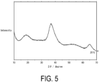
- a peak (P 18° ) is observed near 18° where the 2 ⁇ value is in the range of from 16° to 20° in an X-ray diffraction pattern line, as in a pattern in FIG. 5 .
- a peak (P 37° ) is observed near 37° where the 2 ⁇ value is in the range of from 35° to 39°. Peak shapes of the peak near 18° (P 18° ) and the peak near 37° (P 37° ) are broad.
- the intensity ratio (I 18° /I 37° ) between the peak near 18° (P 18° ) and the peak near 37° (P 37° ) is 0.2 or more. It is preferably 0.25 or more, and more preferably 0.3 or more. It is preferably 2.0 or less, and more preferably 1.5 or less.
- the peak intensity ratio (I 18° /I 37° ) for example, a peak height ratio can be used.
- a peak intensity ratio (I 18° /I 37° ) for example, a peak integrated area ratio can be used.
- the peak height ratio is preferably used. Namely, when the metal element A is nickel, a height ratio (I 18° /I 37° ) between the peak near 18°(P 18° ) and the peak near 37° (P 37° ) is 0.2 or more. It is preferably 0.3 or more, more preferably 0.5 or more, and still more preferably 0.8 or more. It is preferably 3.0 or less, more preferably 2.5 or less, and still more preferably 2.0 or less.
- the height ratio (I 18° /I 37° ) between the peak near 18° (P 18° ) and the peak near 37° (P 37° ) is 0.2 or more. It is preferably 0.25 or more, and more preferably 0.3 or more. It is preferably 2.0 or less, and more preferably 1.5 or less.
- a method for determining the peak height from the X-ray diffraction pattern is, for example, a known method.
- a predetermined peak height may be measured using processing software or the like attached to an X-ray diffraction pattern measuring apparatus.
- the peak heights of the X-ray diffraction pattern a in FIG. 2 could be measured using commercially available graph analysis software, and the intensity ratio (I 18° /I 37° ) between the peak near 18° (P 18° ) to the peak near 37° (P 37° ) was 1.2 using the ratio of the peak heights.
- the metal oxide of the present embodiment has a full width at half maximum (FWHM) of the peak (P 18° ) having the 2 ⁇ value in the range of from 16 to 20 degrees of preferably from 1.0° to 7.0°, and more preferably from 3.0° to 7.0°.
- FWHM full width at half maximum
- the reason why the X-ray diffraction pattern of the metal oxide of the present embodiment indicates a broad peak is unknown at the time of filing the application. It is presumed that this is derived from the fact that extremely small crystals of several nanometers are obtained by a low-temperature producing process. Further, it is presumed that the metal oxide is not a metal oxide of a high-temperature stable phase but a metal oxide of a low-temperature metastable phase because of the low-temperature producing process.
- the method for producing a metal oxide according to the present embodiment includes the following first and second steps, preferably includes first to third steps, and more preferably includes first to fourth steps.
- a mixed solution containing a permanganate salt, a metal salt of the metal element A, and an alcohol is prepared.
- a molar ratio in terms of a metal element between a charged amount of the metal salt of the metal element A and a charged amount of the permanganate salt (A:Mn) is from 1:1.7 to 1:2.3. It is more preferably from 1:1.9 to 1:2.1, and still more preferably 1:2.
- the permanganate salt according to the present embodiment is not particularly limited as long as it has certain solubility in the alcohol used.
- a dissolution rate is preferably 10 mmol/L or more.
- the permanganate salt according to the present embodiment include organic salts of permanganic acid such as tetrabutylammonium permanganate.
- a method for producing an organic salt of permanganic acid is not particularly limited, and can be a known method. For example, an aqueous solution of an alkali metal salt of permanganic acid such as potassium permanganate is mixed with an aqueous solution of an organic halide salt such as tetrabutylammonium bromide to obtain an organic salt of permanganic acid.
- the metal salt of the metal element A according to the present embodiment is not particularly limited as long as it has certain solubility in the alcohol used.
- a dissolution rate is preferably 10 mmol/L or more.
- the metal salt of the metal element A according to the present embodiment include halides of the metal element A such as nickel chloride and copper chloride. These salts may also be hydrates.
- the alcohol according to the present embodiment is not particularly limited as long as it can dissolve at least a part of the permanganate salt according to the present embodiment and the metal salt of the metal element A according to the present embodiment as a reaction solvent.
- the alcohol according to the present embodiment include monohydric alcohols having a hydroxy group, such as methanol and ethanol.
- the alcohol according to the present embodiment may contain other components if necessary.
- an ether-based organic solvent such as 2-dimethoxyethane may be used.
- a proportion of the alcohol to the other components is not particularly limited, and may be from 1:10 to 10:1 or from 1:2 to 2:1 in a volume ratio (v/v).
- An amount of the alcohol used is preferably from 10 to 1000 mL.
- a method for preparing the mixed solution containing a permanganate salt, a metal salt, and an alcohol is not particularly limited.
- Examples of an order of mixing the reactants include an order of preparing a first mixed solution of a metal salt and an alcohol and then adding a permanganate salt or a solution of a permanganate salt to the first mixed solution, and an order of preparing a first mixed solution of a permanganate salt and an alcohol and then adding a metal salt or a solution of a permanganate salt to the first mixed solution.
- a temperature of the mixed solutions is not particularly limited, and the mixed solution may be heated to enhance solubility, and is usually preferably prepared at room temperature.
- a method for stirring the mixed solutions and a stirring time are not particularly limited as long as the mixed solution composed of the permanganate salt, the metal salt, and the alcohol can be sufficiently mixed.
- the mixed solution obtained in the first step is stirred and reacted at a temperature equal to or lower than a boiling point of the alcohol.
- a reaction temperature and a reaction time are not specifically limited, and can be appropriately selected depending on the progress of the reaction, for example, in a range of from 10°C to a boiling point of the solvent used, for a reaction time of from 1 minute to 24 hours.
- the reaction temperature is preferably in a range of from 20°C to the boiling point of the solvent used, more preferably from 20°C to 50°C, still more preferably from 20°C to 30°C, and particularly preferably room temperature (for example, 25°C).
- a reaction atmosphere is not particularly limited and may be, for example, the atmospheric air (atmospheric pressure).
- reaction solution obtained in the previous second step is filtered to obtain a precursor of the metal oxide.
- a filtration method is not particularly limited, and a known method can be used. For example, suction filtration may be used. A step of washing and drying a precipitate may be included. A washing method is not particularly limited, and pure water, ethanol, or a mixed solution thereof can be used.
- the precursor obtained in the third step is heat-treated at a temperature of 20°C or higher and 300°C or lower.
- a heat treatment method is not particularly limited, and examples thereof include a method of heating in the atmospheric air at from 25 to 300°C for from 0.3 to 5 hours.
- a carbon dioxide reduction catalyst of the present embodiment contains the metal oxide of the present embodiment described above.
- the metal oxide of the present embodiment can be used, as it is, as a catalyst.
- Each aspect of the metal oxide of the present embodiment described above can be used.
- the carbon dioxide reduction catalyst of the present embodiment may contain the metal oxide of the present embodiment and a catalyst carrier.
- the catalyst carrier include materials used in ordinary metal-based catalysts.
- the carbon dioxide reduction catalyst of the present embodiment may be supported on a carrier.
- the carrier is preferably a material which is inert to the reaction with the catalyst and excellent in chemical stability, and is preferably quartz, glass, alumina, silica, titanium, copper or the like.
- the shape of the carrier may be any shape as long as the carbon dioxide reduction reaction of the present invention proceeds, and can be any shape such as a plate shape, a fiber shape, a spherical shape, a rectangular shape, or a mesh shape.
- the carbon dioxide reduction method of the present embodiment is a carbon dioxide reduction method by using the metal oxide of the present embodiment as a catalyst. That is, it is a method of reducing carbon dioxide by using the carbon dioxide reduction catalyst of the present embodiment described above to bring carbon dioxide into contact with the catalyst. In the carbon dioxide reduction method of the present embodiment, preferably, carbon dioxide is reduced to produce carbon monoxide.
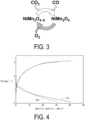
- FIG. 3 is a schematic diagram for explaining an example of a reaction for reducing carbon dioxide using a carbon dioxide reduction catalyst containing a metal oxide of the present embodiment.
- a reaction for reducing carbon dioxide using a carbon dioxide reduction catalyst containing a metal oxide of the present embodiment is shown and explained.
- the present invention is not limited to this mechanism.
- FIG. 3 illustrates an example in which NiMn 2 O 4 obtained in an example of the present invention is used as the metal oxide of the present embodiment.
- the NiMn 2 O 4 described above can function as the carbon dioxide reduction catalyst.
- oxygen ions are removed from the NiMn 2 O 4 by heating or the like as presented in the following Formula (3) to produce oxygen gas. Thereafter, it is considered that it acts on CO 2 on the NiMn 2 O 4 , that a carbon dioxide reduction reaction represented by the following Formula (4) proceeds, and that CO is produced from CO 2 .
- the catalytic reaction by the metal oxide of the present embodiment is not limited thereto.
- the metal oxide of the present embodiment may be used as catalyst materials for other reactions such as a carbon dioxide reduction reaction other than the production of carbon monoxide, other reduction reactions, and further oxidation reactions.
- a reaction temperature of the carbon dioxide reduction is preferably from 50 to 300°C, more preferably from 100 to 250°C, and still more preferably from 100 to 200°C.
- a reaction apparatus for example, a reaction apparatus using a gas and a solid catalyst can be usually used.
- Carbon dioxide introduction method and introduction rate are not particularly limited and can be appropriately selected depending on a reaction scale or the like.
- a reaction pressure of the carbon dioxide reduction is not particularly limited and is preferably from 0.1 to 10 5 Pa and more preferably the atmospheric pressure.
- Carbon monoxide produced by the carbon dioxide reduction method of the present embodiment can be discharged to the outside of the reaction system and used as an industrial raw material.
- the carbon dioxide reduction apparatus of the present embodiment is an apparatus for reducing carbon dioxide, and includes an introduction unit for carbon dioxide; a reaction unit including a carbon dioxide reduction catalyst; and a heating unit configured to heat the reaction unit.
- the carbon dioxide reduction catalyst includes various aspects of the metal oxide of the present embodiment described above.
- the introduction unit for carbon dioxide described above is not particularly limited, and, for example, a gas introduction unit used in a known gas reactor can be used.
- the reaction unit including the carbon dioxide reduction catalyst is not particularly limited, and, for example, a gas phase reaction apparatus using a solid catalyst can be used.
- the heating unit is not particularly limited, and various known heating means can be used.
- An electrode material of the present embodiment contains the metal oxide according to the present embodiment.
- a positive electrode material for a magnesium battery contains the metal oxide of the present embodiment.
- a positive electrode active material of the positive electrode material for a magnesium battery is preferably the metal oxide of the present embodiment.
- An example of the positive electrode material for a magnesium battery will be described below, but the electrode material of the present embodiment is not particularly limited to the positive electrode material for a magnesium battery.
- Magnesium has a large electric capacity per unit volume because its ion is a multivalent ion.
- magnesium has a high melting point and is safe, and, advantageously, has a small bias in resource distribution on the earth, is abundant in resource amount, and is inexpensive. Therefore, a magnesium battery using metal magnesium as a negative electrode has attracted attention as a next-generation battery replacing a lithium battery.
- the magnesium battery of the present embodiment includes a positive electrode, a negative electrode, and an electrolytic solution. Usually, a separator is provided between the positive electrode and the negative electrode.
- the reaction of magnesium means, for example, dissolution and precipitation of magnesium at an interface between metallic magnesium and the electrolytic solution, an intercalation reaction of magnesium ions in a carbon-based material, alloying reaction of magnesium with an element such as bismuth, and absorption and desorption of magnesium ions onto and from a battery material such as titanium dioxide at a low potential such as 1 V or lower.
- a battery material such as titanium dioxide at a low potential such as 1 V or lower.
- the type of the magnesium battery include a primary battery, a secondary battery, an air battery, and an electric double layer capacitor, and a secondary battery is preferable.
- the magnesium battery using the positive electrode material composed of the metal oxide of the present embodiment will be described using an example of a magnesium secondary battery.
- the magnesium battery of the present embodiment is not particularly limited to the secondary battery.
- a shape of the magnesium secondary battery according to the present embodiment is not limited.
- Examples of the shape include a coin shape, a button shape, a sheet shape, a laminate shape, a cylindrical shape, a flat shape, and a square shape.
- the positive electrode according to the present embodiment includes a current collector and a positive electrode active material layer formed on a surface of the current collector.
- the positive electrode active material layer contains the positive electrode material of the present embodiment as a positive electrode active material. In addition, it may further contain a conductive aid and a binder.
- the current collector in the positive electrode of the present invention is composed of a conductive material such as platinum, copper, stainless steel (SUS), aluminum, iron, chromium, nickel, titanium, or carbon.
- the current collector may be in the form of a net (mesh), a sheet, or the like. Specific examples of a positive electrode current collector include an aluminum mesh.
- the positive electrode active material layer according to the present embodiment contains the positive electrode material of the present embodiment as the positive electrode active material.
- the positive electrode active material layer according to the present embodiment contains a metal material of the present embodiment as the positive electrode active material.
- the metal material of the present embodiment includes various preferred embodiments and specific examples as described above. In addition, materials which will be described in Examples below are also included.
- the positive electrode active material layer according to the present embodiment may also contain another positive electrode active material as the positive electrode active material.
- the other positive electrode active material is not particularly limited, and a known active material usually used as an active material in a magnesium battery other than the metal material of the present embodiment can be used.
- Examples of the other positive electrode active material include transition metal oxides; transition metal elements; conductive polymers such as polyacetylene, polyaniline, polypyrrole, polythiophene, and polyparaphenylene and derivatives thereof; and disulfide compounds.
- a thickness of the active material layer in the positive electrode of the present invention is not particularly limited, but is usually 1 ⁇ m or more and 1000 ⁇ m or less, preferably 1 ⁇ m or more and 500 ⁇ m or less, and more preferably 1 ⁇ m or more and 300 ⁇ m or less.
- a content of the electrode material of the present embodiment in 100 mass% of a total positive electrode active material in the positive electrode active material layer of the present embodiment is 50 mass% or more, preferably 80 mass% or more, and more preferably 90 mass% or more.
- the content of the metal material of the present embodiment in 100 mass% of the electrode material of the present embodiment is 80 mass% or more, preferably 90 mass% or more, more preferably 95 mass% or more, and particularly preferably 100%.
- Examples of the conductive aid of the present embodiment include carbon black such as acetylene black, ketjen black, furnace black, and thermal black. Among them, acetylene black is preferable.
- a content of the conductive aid is not particularly limited, but is, for example, usually 1 mass% or more and 50 mass% or less, preferably 5 mass% or more and 30 mass% or less, and more preferably 10 mass% or more and 20 mass% or less with respect to a total mass of the positive electrode active material layer.
- binder of the present embodiment examples include polyvinylidene fluoride (PVDF), polytetrafluoroethylene (PTFE), carboxymethyl cellulose (CMC), styrene-butadiene copolymer (SBR), acrylonitrile-butadiene copolymer (NBR), polyacrylonitrile (PAN), ethylenevinyl alcohol copolymer (EVOH), polyurethane, polyacrylate, polyvinyl ether, polyamide, and polyimide.
- PVDF polyvinylidene fluoride
- PTFE polytetrafluoroethylene
- CMC carboxymethyl cellulose
- SBR styrene-butadiene copolymer
- NBR acrylonitrile-butadiene copolymer
- PAN polyacrylonitrile
- EVOH ethylenevinyl alcohol copolymer
- polyurethane polyacrylate, polyvinyl ether, polyamide, and polyimide.
- a content of the binder is not particularly limited, but is, for example, usually 1 mass% or more and 50 mass% or less, preferably 5 mass% or more and 30 mass% or less, and more preferably 10 mass% or more and 20 mass% or less with respect to the total mass of the positive electrode active material layer.
- a total mass of the binders may be the above-described content.
- the positive electrode of the present invention can be produced by applying or pressurebonding the positive electrode material composition of the present embodiment onto the current collector, and drying the composition.
- the positive electrode material composition of the present embodiment contains the positive electrode material of the present embodiment as the positive electrode active material. In addition, it may further contain a conductive aid and a binder.
- an amount of the positive electrode material composition of the present embodiment to be used may be appropriately set so that the dried active material layer has a desired thickness.
- the positive electrode material composition of the present embodiment may be applied onto the current collector according to a method known per se, and application may be performed using, for example, a self-propelled coater, an inkjet method, a doctor blade method, a spray method, or a combination thereof as a specific application method.
- drying of the positive electrode material composition of the present invention on the current collector may be performed according to a known method, and is usually performed by a heat treatment. Drying conditions during heating, such as necessity of vacuum, a drying time, and a drying temperature, may be appropriately set according to an amount of the positive electrode material composition of the present invention to be applied and a volatilization rate thereof.
- a specific drying method may be, for example, drying in vacuum at usually 50°C or higher and 150°C or lower, preferably 70°C or higher and 130°C or lower for usually 1 hour or more and 20 hours or less, preferably 3 hours or more and 12 hours or less.
- a press treatment may be performed after drying.
- Examples of the press treatment according to the present embodiment include a calender roll method and a flat plate press method, and the calender roll method is preferable.
- a negative electrode active material constituting the negative electrode of the present embodiment is not particularly limited, and examples thereof include metal magnesium, a magnesium-containing alloy, a metal or an alloy capable of being alloyed with magnesium, an oxide capable of doping and dedoping magnesium ions, a transition metal nitride capable of doping and dedoping magnesium ions, and a carbon material capable of doping and dedoping magnesium ions.
- the negative electrode is any appropriate electrode configured to adsorb magnesium and desorb magnesium ions.
- the negative electrode may include any appropriate active material layer configured to adsorb and desorb magnesium ions.
- the active material of the negative electrode is not limited to a specific material.
- the separator of the present embodiment is not particularly limited as long as the negative electrode and the positive electrode can be electrically insulated from each other so that a nonaqueous electrolyte solution which will be described below permeates the separator.
- Examples of the separator of the present embodiment include a porous synthetic resin film such as a porous film made of a polyolefin polymer.
- Specific examples of the porous film include porous films made of polyethylene polymer and porous films made of polypropylene.
- the electrolytic solution of the present embodiment is not particularly limited as long as magnesium ions can be guided between the negative electrode and the positive electrode, and may be any appropriate electrolytic solution such as a nonaqueous magnesium ion conductor.
- the nonaqueous electrolytic solution of the present embodiment include an electrolytic solution containing an electrolyte and an organic solvent.
- Examples of the solvent in the electrolytic solution according to the present invention include ether-based solvents such as diethyl ether, tetrahydrofuran, 2-methyltetrahydrofuran, diisopropyl ether, 1,2-dimethoxyethane, diethylene glycol dimethyl ether (diglyme), triethylene glycol dimethyl ether (triglyme) and tetraethylene glycol dimethyl ether (tetraglyme); halogenated hydrocarbon-based solvents such as dichloromethane and chloroform; carbonatebased solvents such as dimethyl carbonate and diethyl carbonate; nitrile-based solvents such as acetonitrile; and sulfone-based solvents such as sulfolane, dimethyl sulfone and ethyl methyl sulfone.
- ether-based solvents such as diethyl ether, tetrahydrofuran, 2-methyltetrahydrofuran, diisopropyl
- ether-based solvents and sulfone-based solvents are preferable, and ether-based solvents are preferable.
- tetrahydrofuran, 1,2-dimethoxyethane, diglyme, triglyme, tetraglyme, and sulfolane are preferable; tetrahydrofuran, diglyme, triglyme, and tetraglyme are more preferable; and tetrahydrofuran and triglyme are still more preferable.
- a mixture of two or more of these solvents may be used.
- Examples of the electrolyte contained in the electrolytic solution of the present embodiment include a Lewis basic organomagnesium compound RMgX.
- R is selected from the group consisting of alkyl ligands such as methyl, ethyl, and butyl, aryl, benzyl, amide, naphthal, phenyl, alkenyl, alkynyl or derivatives thereof.
- X is a halide such as F, Cl, Br, or I.
- the electrolyte further contains a Lewis acid compound that causes a metal exchange reaction.
- the Lewis acid compound examples include, but are not limited to, AlCl 3 , BCl 3 , AlCl 2 Et, FeCl 2 , FeCl 3 , and TiCl 4 .
- the electrolyte further contains a salt.
- Examples of the salt include, but are not limited to, MgCl 2 , Mg(ClO 4 ) 2 , Mg(BF 4 ) 2 , Mg(AsF 6 ) 2 , Mg(PF 6 ) 2 , Mg(CF 3 SO 3 ) 2 , Mg[N(CF 3 SO 2 ) 2 ] 2 , Mg[C(SO 2 CF 3 ) 3 ] 2 , LiCl, LiClO 4 , LiBF 4 , LiAsF 6 , LiPF 6 , Li(CF 3 SO 3 ), LiN(CF 3 SO 2 ) 2 , LiC(SO 2 CF 3 ) 3 , NaCl, NaClO 4 , NaBF 4 , NaAsF 6 , NaPF 6 , Na(CF 3 SO 3 ), NaN(CF 3 SO 2 ) 2 , and NaC(SO 2 CF 3 ) 3 .
- An example of the electrolytic solution of the present embodiment is a mixture of compound A, aluminum compound B, and ether-based solvent C which will be described below.
- Tetrahydrofuran diglyme, triglyme, or tetraglyme.
- a mixture of B(OMgCl) 3 or C 6 H 5 B(OMgCl) 2 , aluminum (III) chloride, and tetrahydrofuran, triglyme or a mixed solvent of these two species is preferable.
- a mixture of B(OMgCl) 3 , aluminum (III) chloride, and tetrahydrofuran, triglyme, or a mixed solvent of two species thereof is particularly preferable.
- electrolyte contained in the electrolytic solution of the present embodiment include “MaglutionTMB01” (B(OMgCl) 3 -AlCl 3 complex (1:6)/triglyme solution), “MaglutionTMB0 2 " (B(OMgCl) 3 -AlCl 3 complex (1:6)/triglyme-tetrahydrofuran (50:50 vol%) solution), and MgTFSA 2 available from Kishida Chemical Co., Ltd. (Mg[N(CF 3 SO 2 ) 2 ] 2 )/triglyme solution.
- Potassium permanganate (3.16 g) was dissolved in pure water (100 mL) to prepare an aqueous potassium permanganate solution.
- Tetrabutylammonium bromide (6.45 g) was dissolved in pure water (50 mL) to prepare an aqueous tetrabutylammonium bromide solution.
- the aqueous tetrabutylammonium bromide solution was added dropwise while the aqueous potassium permanganate solution was stirred, and the mixture was stirred for 1 hour, and then the produced precipitate was sucked and filtered.
- the obtained precipitate was washed with 200 mL of pure water and dried under reduced pressure at 25°C to obtain 6 g of tetrabutylammonium permanganate.
- a nickel chloride hexahydrate (475 mg) was dissolved in a mixed solvent of methanol (25 mL) and 1,2-dimethoxyethane (25 mL) to prepare a first mixed solution.
- the tetrabutylammonium permanganate obtained in Synthesis Example 1 was added in an amount of 723 mg to the first solution in one time to obtain a second mixed solution.
- the second mixed solution was stirred at 25°C for 1 hour to generate a precipitate, thereby obtaining a third mixed solution.
- the precipitate obtained by suction filtration of the third mixed solution was washed with 300 mL of pure water and 300 mL of ethanol in this order, and dried at 100°C for 12 hours. Thereafter, it was held at 25°C for 2 hours. 200 mg of NiMn 2 O 4 powder (NMO-1) of the present example was obtained.
- NiMn 2 O 4 powder (NMO-2) to powder (NMO-7) of Examples 2 to 7 were obtained in the same manner as in Example 1, except that they were held at 100°C, 150°C, 200°C, 250°C, 300°C, and 350°C, respectively, for 2 hours, instead of being held at 25°C for 2 hours, in the atmospheric air in Examples 2 to 7.
- Comparative Examples 1 to 3 200 mg each of metal oxide powder (cNMO-1) to powder (cNMO-3) of Comparative Examples 1 to 3 were obtained in the same manner as in Example 1, except that they were held at 400°C, 600°C, and 800°C, respectively, for 2 hours, instead of being held at 25°C for 2 hours in Example 1.
- Example 2 After 100 mg of the NiMn 2 O 4 powder sample (NMO-2) obtained in Example 2 was weighed, it was placed in a thermogravimeter and held at 100°C in a built-in electric oven while flowing carbon dioxide (flow rate: 100 ml/min or less, CO 2 concentration (99.9%)). After holding the sample for 150 minutes, the CO concentration (unit: volume ppmor or mass ppm) in the gas after flowing was measured by gas chromatography. The results are indicated in Table 1.
- the powder sample (NMO-2) was held at 100°C in the electric furnace for 1000 minutes while flowing carbon dioxide, and then cooled to room temperature. A powder sample (NMO-2') after the reaction was taken out.
- the CO concentration in the gas after flowing was measured in the same manner as in Example 8, except that the gas was held at 250°C and 350°C in the electric furnace instead of being held at 100°C in the electric furnace. The results are indicated in Table 1.
- Example 9 Example 9 (250°C) and Example 10 (350°C) as compared with that in Example 8 (100°C). It is believed that the high temperature process increased the rate of reaction from carbon dioxide to CO. Meanwhile, the CO concentration was decreased in Example 10 (350°C) as compared with that in Example 9 (250°C). Although the reaction rate was increased due to the higher reaction temperature, the carbon dioxide conversion amount was decreased. The main cause is believed to be that the NiMn 2 O 4 powder (NMO-1) obtained in Example 1 was changed to the metal oxide (NMO-7) obtained in Example 7 at 350°C, as illustrated in FIG. 2 (pattern g) of Example 7. Therefore, it is presumed that the catalytic effect on the reaction of reducing carbon dioxide would be weakened.
- the XRD patterns h and i of Comparative Examples 1 and 2 in FIG. 2 coincide with the XRD pattern of NiMnOs crystals
- the XRD pattern j of Comparative Example 3 in FIG. 2 coincides with the XRD pattern of NiMn 2 O 4 crystals which are spinel crystals.
- NiMn 2 O 4 powder samples of Examples 1 to 7 are presumed to be spinel crystals of a low-temperature metastable phase in contrast to the high-temperature stable phase of Comparative Example 3. That is, it is believed that, in Example 7 (350°C), the phase starts to change until it does not correspond to a low-temperature metastable phase like the metal oxide of the present embodiment, and the performance itself of the catalyst decreases.
- a positive electrode material composition was prepared by mixing 60 parts by mass of the NiMn 2 O 4 powder (NMO-1) obtained in Example 1, 30 parts by mass of acetylene black (conductive aid: FX-35, available from Denka Company Limited), and 10 parts by mass of polytetrafluoroethylene (binder: 6-J, Mitsui Chemicals, Inc.).
- the positive electrode material composition was used to pressure-bond a positive electrode active material layer (thickness: about 30 ⁇ m) onto a current collector made of an aluminum mesh (The Nilaco Corporation, 100 mesh), and a vacuum heat treatment was performed at 100°C for 12 hours to produce a positive electrode.
- the positive electrode, a negative electrode, a reference electrode, and an electrolytic solution were set in a 2032 type coin cell in a glove box filled with argon gas to produce a magnesium battery.
- Metal magnesium foil was used as the negative electrode, and a Mg[N(CF 3 SO 2 ) 2 ] 2 /triglyme solution was used as the electrolytic solution.
- the Mg[N(CF 3 SO 2 ) 2 ] 2 /triglyme solution was prepared in advance by dissolving 0.3 M of MgTFSA 2 (magnesium bis(trifluoromethanesulfonyl)amide, Kishida Chemical Co., Ltd.) in triglyme (Kanto Chemical Co., Inc.).
- the fabricated battery was subjected to a charge-discharge test at a current density of 10 mAg -1 and an operating temperature of 50°C. The results are illustrated in FIG. 4 .
- CuMn 2 O 4 powder (CMO-1) powder (200 mg) of the present example was obtained in the same manner as in Example 1, except that 199 mg of a copper acetate hydrate was used instead of 475 mg of the nickel chloride hexahydrate.
Landscapes
- Chemical & Material Sciences (AREA)
- Organic Chemistry (AREA)
- Engineering & Computer Science (AREA)
- Materials Engineering (AREA)
- Chemical Kinetics & Catalysis (AREA)
- Inorganic Chemistry (AREA)
- Inorganic Compounds Of Heavy Metals (AREA)
- Catalysts (AREA)
Abstract
Description
- The present invention relates to a metal oxide having a spinel-type crystal structure, a method for producing the same, a carbon dioxide reduction method using the metal oxide, and a carbon dioxide reduction apparatus.
- There is an issue of global warming caused by an increase in concentration of carbon dioxide (CO2) in the atmospheric air because a large amount of carbon dioxide is discharged by burning fossil fuel in various plants or the like. Meanwhile, carbon monoxide is produced using fossil fuel as a raw material. When natural gas is used as a raw material for carbon monoxide, a mixed gas of carbon monoxide and hydrogen is obtained by steam-reforming the natural gas, and this mixed gas is further used as a raw material for various chemical products.
- In order to solve the issue that a large amount of carbon dioxide is discharged, attention has been paid to a reaction for reducing carbon dioxide to carbon monoxide (CO). Research on a catalyst for reducing carbon dioxide has been actively conducted throughout the world. In particular, many metal oxides having excellent nature as a carbon dioxide reduction catalyst have been reported.
- For example, Non-Patent
Literature 1 discloses a carbon dioxide reduction catalyst using a spinel-type metal oxide such as Co3O4. -
Patent Literature 1 discloses a carbon dioxide reduction catalyst using a spinel-type composite metal oxide such as CuCo2O4 or MnCo2O4. - Non-Patent
Literature 2 discloses a carbon dioxide reduction catalyst using Ge-doped CeO2. - Patent Literature 1:
JP 2021-023840 A -
- Non-Patent Literature 1: S. Gao, et al., "Ultrathin Co3O4 Layers Realizing Optimized CO2 Electroreduction to Formate", Angew. Chem. Int. Ed., 2016, 55, 698
- Non-Patent Literature 2: J.M.Serra, et al., "Hydrogen Production via Microwave-Induced Water Splitting at Low Temperature", Nature Energy 5 pp.910-919 (2020)
- The carbon dioxide reduction method of
Non-Patent Literature 1 utilizes electrochemical reduction. Therefore, electric energy is consumed. The carbon dioxide reduction method ofPatent Literature 1 utilizes photoreduction. Therefore, it is necessary to use it together with a light absorber which absorbs light and converts it into electron energy. The carbon dioxide reduction method ofNon-Patent Literature 2 utilizes reduction while heating with microwaves. Therefore, a microwave supply power source is required. - An object of the present invention is to provide a carbon dioxide reduction catalyst capable of reducing carbon dioxide under mild conditions, a carbon dioxide reduction method using the carbon dioxide reduction catalyst, and a carbon dioxide reduction apparatus.
- Another object of the present invention is to provide a method for producing a catalyst at a lower temperature, focusing also on energy consumed in a method for producing a carbon dioxide reduction catalyst from a total viewpoint, in addition to reduction in energy required for the carbon dioxide reduction method.
- To solve the issues described above, the present invention is configured as follows.
- [1] A metal oxide, containing a metal element A, manganese, and oxygen and having a spinel-type crystal structure,
- in which the A is at least one metal element selected from the group consisting of nickel, magnesium, zinc, copper, and iron;
- a molar composition ratio of manganese to oxygen is from 1:1.8 to 1:2.2;
- a molar composition ratio of the metal element A to manganese is from 1:1.7 to 1:2.3; and
- in an X-ray diffraction pattern obtained by X-ray diffraction measurement using a Cu-Kα ray, the metal oxide has an intensity ratio (I18°/I37°) of 0.2 or more between a peak having a 2θ value in a range of from 16° to 20° (P18°) and a peak having a 2θ value in a range of from 35° to 39° (P37°).
- The A is preferably at least one metal element selected from the group consisting of nickel and copper.
- [2] The metal oxide according to [1], in which in the X-ray diffraction pattern obtained by X-ray diffraction measurement using a Cu-Kα ray, the metal oxide has a full width at half maximum (FWHM) of the peak (P18°) having the 2θ value in the range of from 16 to 20 degrees of from 1.0° to 7.0°.
- [3] The metal oxide according to [1] or [2], having an average particle size of from 1 to 10 nm.
- [4] The metal oxide according to any one of [1] to [3], containing a compound represented by Formula (1):
AMn2O4 (1)
where in Formula (1), A is at least one selected from the group consisting of Ni and Cu, which is the same as the metal element A. - [5] A method for producing the metal oxide described in any one of [1] to [4], the method including:
- a first step of preparing a mixed solution containing a permanganate salt, a metal salt of the metal element A, and an alcohol; and
- a second step of stirring and reacting the mixed solution obtained in the first step at a temperature equal to or lower than a boiling point of the alcohol,
- in which the A is at least one metal element selected from the group consisting of nickel and copper; and
- a molar ratio in terms of a metal element between a charged amount of the metal salt of the metal element A and a charged amount of the permanganate salt (A:Mn) is from 1:1.7 to 1:2.3.
- [6] A method for producing a metal oxide, the metal oxide containing a metal element A, manganese, and oxygen and having a spinel-type crystal structure, the method including:
- a first step of preparing a mixed solution containing a permanganate salt, a metal salt of the metal element A, and an alcohol; and
- a second step of stirring and reacting the mixed solution obtained in the first step at a temperature equal to or lower than a boiling point of the alcohol,
- in which the A is at least one metal element selected from the group consisting of nickel and copper;
- a molar composition ratio of manganese to oxygen is from 1:1.8 to 1:2.2; and
- a molar composition ratio of the metal element A to manganese is from 1:1.7 to 1:2.3.
- [7] The method for producing a metal oxide according to [5] or [6],
- in which the permanganate salt is tetrabutylammonium permanganate; and
- the metal salt is at least one selected from the group consisting of nickel chloride and copper chloride.
- [8] The method for producing a metal oxide according to any one of [5] to [7], further including:
- a third step of obtaining a precursor of the metal oxide by filtering a reaction solution obtained in the second step; and
- a fourth step of heat-treating the precursor obtained in the third step at a temperature of 20°C or higher and 300°C or lower.
- [9] A metal oxide obtained by using the method for producing a metal oxide described in [6].
- [10] A carbon dioxide reduction catalyst containing the metal oxide described in any one of [1] to [4] and [9].
- [11] A carbon dioxide reduction method for reducing carbon dioxide using the metal oxide described in any one of [1] to [4] and [9],
in which a reaction temperature in the carbon dioxide reduction reaction is 300°C or lower. - [12] A carbon dioxide reduction apparatus for reducing carbon dioxide, including:
- an introduction unit for carbon dioxide;
- a reaction unit including a carbon dioxide reduction catalyst; and
- a heating unit configured to heat the reaction unit;
- in which the carbon dioxide reduction catalyst contains the metal oxide described in any one of [1] to [4] and [9].
- [13] A positive electrode material for a magnesium battery, containing the metal oxide described in any one of [1] to [4] and [9].
- [14] An active material layer of a positive electrode material for a magnesium battery, including the positive electrode material described in [13].
- [15] A positive electrode for a magnesium battery including: the active material layer of a positive electrode material described in [14]; and a current collector.
- [16] A magnesium battery including: the positive electrode for a magnesium battery described in [15]; a negative electrode for a magnesium battery; and an electrolytic solution.
- An object of the present invention is to provide a carbon dioxide reduction catalyst capable of reducing carbon dioxide under mild conditions, a carbon dioxide reduction method using the carbon dioxide reduction catalyst, and a carbon dioxide reduction apparatus.
- Another object of the present invention is to provide a method for producing a catalyst at a low temperature. Carbon dioxide can be reduced with less energy from the viewpoint of overall energy consumption involving catalyst production and carbon dioxide reduction steps.
-
-
FIG. 1 is a transmission electron microscope (TEM) view of a metal oxide obtained in Example 1. -
FIG. 2 illustrates X-ray diffraction (XRD) patterns of metal oxides obtained in Examples 1 to 7 and Comparative Examples 1 to 3. InFIG. 2 , the X-ray diffraction (XRD) patterns of Examples 1 to 7 and Comparative Examples 1 to 3 are pattern a to pattern j, respectively. -
FIG. 3 is a schematic diagram for explaining an example of a reaction for reducing carbon dioxide using a carbon dioxide reduction catalyst containing a metal oxide of the present embodiment. -
FIG. 4 is a graph for evaluating charge/discharge characteristics of a magnesium secondary battery fabricated using the metal oxide of the present embodiment in Example 10. -
FIG. 5 is an X-ray diffraction (XRD) pattern of a metal oxide obtained in Example 11. - Hereinafter, embodiments of a metal oxide, a method for producing the same, a carbon dioxide reduction method, and a carbon dioxide reduction apparatus according to the present invention will be described in detail. The present invention is not limited only to the following embodiments.
- A metal oxide of the present embodiment includes a metal element A, manganese, and oxygen and has a spinel-type crystal structure. The A is at least one metal element selected from the group consisting of nickel, magnesium, zinc, copper, and iron, and is preferably at least one metal element selected from the group consisting of nickel and copper. In the metal oxide, a molar composition ratio of manganese to oxygen is from 1:1.8 to 1:2.2, and a molar composition ratio of the metal element A to manganese is from 1:1.7 to 1:2.3. In an X-ray diffraction pattern obtained by X-ray diffraction measurement using a Cu-Kα ray, the metal oxide has an intensity ratio (I18°/I37°) of 0.2 or more between a peak having a 2θ value in a range of from 16° to 20° (P18°) and a peak having a 2θ value in a range of from 35° to 39° (P37°).
- In the metal oxide of the present embodiment, the molar composition ratio of manganese to oxygen is preferably from 1:1.9 to 1:2.1, more preferably from 1:1.95 to 1:2.05, and still more preferably 1:2.
- In the metal oxide of the present embodiment, the molar composition ratio of the metal element A to manganese is preferably from 1:1.8 to 1:2.2, more preferably from 1:1.9 to 1:2.1, and still more preferably 1:2.
- In the metal oxide of the present embodiment, preferably the molar composition ratio of manganese to oxygen is 1:2 and the molar composition ratio of the metal element A to manganese is from 1:1.8 to 1:2.2; more preferably the molar composition ratio of manganese to oxygen is 1:2 and the molar composition ratio of the metal element A to manganese is from 1:1.9 to 1:2.1; and still more preferably the molar composition ratio of manganese to oxygen is 1:2 and the molar composition ratio of the metal element A to manganese is 1:2.
- The metal oxide of the present embodiment preferably contains a compound represented by Formula (1). It is more preferably a compound represented by Formula (1).
AMn2O4 (1)
- In the Formula (1), A is the same as the metal element A.
- In the metal oxide of the present embodiment, the metal element A is preferably nickel.
- The metal oxide of the present embodiment preferably contains a compound represented by Formula (2). It is more preferably a compound represented by Formula (2).
NiMn2O4 (2)
- The metal oxide of the present embodiment is not particularly limited, but has an average particle size of preferably from 0.5 to 10 nm, and more preferably from 0.5 to 5 nm. The average particle size is still more preferably from 0.5 to 3 nm.
- As a method for evaluating the average particle size, a known method can be used. For example, evaluation can be performed using a scanning electron microscope (SEM), a transmission electron microscope (TEM), or the like. For example, 2 to 5 nm nanoparticles were observed from the TEM view of a metal oxide of Example 1 which will be described below in
FIG. 1 . - Further, the average particle size here means a primary particle size of the metal oxide. When the metal oxide is in the form of a powder, a particle size of the powder is a secondary particle size, and primary particles are aggregated to form secondary particles.
- An X-ray used for a powder X-ray diffraction pattern of the metal oxide of the present embodiment is preferably a characteristic X-ray of Cu-kα. When the metal element A of the metal oxide of the present embodiment is, for example, nickel, a peak (P18°) is observed near 18° where the 2θ value is in the range of from 16° to 20° in an X-ray diffraction pattern line, as in pattern a in
FIG. 2 . A peak (P37°) is observed near 37° where the 2θ value is in the range of from 35° to 39°. Peak shapes of the peak near 18° (P18°) and the peak near 37° (P37°) are broad. In the powder X-ray diffraction pattern of the metal oxide of the present embodiment, when the metal element A is nickel, an intensity ratio (I18°/I37°) between the peak near 18°(P18°) and the peak near 37° (P37°) is 0.2 or more. It is preferably 0.3 or more, more preferably 0.5 or more, and still more preferably 0.8 or more. It is preferably 3.0 or less, more preferably 2.5 or less, and still more preferably 2.0 or less. - When the metal element A of the metal oxide of the present embodiment is, for example, copper, a peak (P18°) is observed near 18° where the 2θ value is in the range of from 16° to 20° in an X-ray diffraction pattern line, as in a pattern in
FIG. 5 . A peak (P37°) is observed near 37° where the 2θ value is in the range of from 35° to 39°. Peak shapes of the peak near 18° (P18°) and the peak near 37° (P37°) are broad. In the powder X-ray diffraction pattern of the metal oxide of the present embodiment, when the metal element A is copper, the intensity ratio (I18°/I37°) between the peak near 18° (P18°) and the peak near 37° (P37°) is 0.2 or more. It is preferably 0.25 or more, and more preferably 0.3 or more. It is preferably 2.0 or less, and more preferably 1.5 or less. - In the present invention, as the peak intensity ratio (I18°/I37°), for example, a peak height ratio can be used. Alternatively, as the peak intensity ratio (I18°/I37°), for example, a peak integrated area ratio can be used. From the viewpoint of difficulty of evaluation, the peak height ratio is preferably used. Namely, when the metal element A is nickel, a height ratio (I18°/I37°) between the peak near 18°(P18°) and the peak near 37° (P37°) is 0.2 or more. It is preferably 0.3 or more, more preferably 0.5 or more, and still more preferably 0.8 or more. It is preferably 3.0 or less, more preferably 2.5 or less, and still more preferably 2.0 or less. When the metal element A is copper, the height ratio (I18°/I37°) between the peak near 18° (P18°) and the peak near 37° (P37°) is 0.2 or more. It is preferably 0.25 or more, and more preferably 0.3 or more. It is preferably 2.0 or less, and more preferably 1.5 or less.
- A method for determining the peak height from the X-ray diffraction pattern is, for example, a known method. For example, a predetermined peak height may be measured using processing software or the like attached to an X-ray diffraction pattern measuring apparatus. For example, in Example 1 which will be described below, the peak heights of the X-ray diffraction pattern a in
FIG. 2 could be measured using commercially available graph analysis software, and the intensity ratio (I18°/I37°) between the peak near 18° (P18°) to the peak near 37° (P37°) was 1.2 using the ratio of the peak heights. - In the X-ray diffraction pattern obtained by X-ray diffraction measurement using a Cu-Kα ray, the metal oxide of the present embodiment has a full width at half maximum (FWHM) of the peak (P18°) having the 2θ value in the range of from 16 to 20 degrees of preferably from 1.0° to 7.0°, and more preferably from 3.0° to 7.0°. The reason why the X-ray diffraction pattern of the metal oxide of the present embodiment indicates a broad peak is unknown at the time of filing the application. It is presumed that this is derived from the fact that extremely small crystals of several nanometers are obtained by a low-temperature producing process. Further, it is presumed that the metal oxide is not a metal oxide of a high-temperature stable phase but a metal oxide of a low-temperature metastable phase because of the low-temperature producing process.
- Next, a method for producing a metal oxide of the present embodiment will be described.
- The method for producing a metal oxide according to the present embodiment includes the following first and second steps, preferably includes first to third steps, and more preferably includes first to fourth steps.
- In this step, a mixed solution containing a permanganate salt, a metal salt of the metal element A, and an alcohol is prepared. A molar ratio in terms of a metal element between a charged amount of the metal salt of the metal element A and a charged amount of the permanganate salt (A:Mn) is from 1:1.7 to 1:2.3. It is more preferably from 1:1.9 to 1:2.1, and still more preferably 1:2.
- The permanganate salt according to the present embodiment is not particularly limited as long as it has certain solubility in the alcohol used. For example, a dissolution rate is preferably 10 mmol/L or more. Examples of the permanganate salt according to the present embodiment include organic salts of permanganic acid such as tetrabutylammonium permanganate. A method for producing an organic salt of permanganic acid is not particularly limited, and can be a known method. For example, an aqueous solution of an alkali metal salt of permanganic acid such as potassium permanganate is mixed with an aqueous solution of an organic halide salt such as tetrabutylammonium bromide to obtain an organic salt of permanganic acid.
- The metal salt of the metal element A according to the present embodiment is not particularly limited as long as it has certain solubility in the alcohol used. For example, a dissolution rate is preferably 10 mmol/L or more. Examples of the metal salt of the metal element A according to the present embodiment include halides of the metal element A such as nickel chloride and copper chloride. These salts may also be hydrates.
- The alcohol according to the present embodiment is not particularly limited as long as it can dissolve at least a part of the permanganate salt according to the present embodiment and the metal salt of the metal element A according to the present embodiment as a reaction solvent. Examples of the alcohol according to the present embodiment include monohydric alcohols having a hydroxy group, such as methanol and ethanol. The alcohol according to the present embodiment may contain other components if necessary. For example, an ether-based organic solvent such as 2-dimethoxyethane may be used. A proportion of the alcohol to the other components is not particularly limited, and may be from 1:10 to 10:1 or from 1:2 to 2:1 in a volume ratio (v/v).
- An amount of the alcohol used is preferably from 10 to 1000 mL.
- In this step, a method for preparing the mixed solution containing a permanganate salt, a metal salt, and an alcohol is not particularly limited.
- Examples of an order of mixing the reactants include an order of preparing a first mixed solution of a metal salt and an alcohol and then adding a permanganate salt or a solution of a permanganate salt to the first mixed solution, and an order of preparing a first mixed solution of a permanganate salt and an alcohol and then adding a metal salt or a solution of a permanganate salt to the first mixed solution.
- A temperature of the mixed solutions is not particularly limited, and the mixed solution may be heated to enhance solubility, and is usually preferably prepared at room temperature.
- A method for stirring the mixed solutions and a stirring time are not particularly limited as long as the mixed solution composed of the permanganate salt, the metal salt, and the alcohol can be sufficiently mixed.
- In this step, the mixed solution obtained in the first step is stirred and reacted at a temperature equal to or lower than a boiling point of the alcohol.
- A reaction temperature and a reaction time are not specifically limited, and can be appropriately selected depending on the progress of the reaction, for example, in a range of from 10°C to a boiling point of the solvent used, for a reaction time of from 1 minute to 24 hours. The reaction temperature is preferably in a range of from 20°C to the boiling point of the solvent used, more preferably from 20°C to 50°C, still more preferably from 20°C to 30°C, and particularly preferably room temperature (for example, 25°C).
- A reaction atmosphere is not particularly limited and may be, for example, the atmospheric air (atmospheric pressure).
- In this step, the reaction solution obtained in the previous second step is filtered to obtain a precursor of the metal oxide.
- A filtration method is not particularly limited, and a known method can be used. For example, suction filtration may be used. A step of washing and drying a precipitate may be included. A washing method is not particularly limited, and pure water, ethanol, or a mixed solution thereof can be used.
- In this step, the precursor obtained in the third step is heat-treated at a temperature of 20°C or higher and 300°C or lower.
- A heat treatment method is not particularly limited, and examples thereof include a method of heating in the atmospheric air at from 25 to 300°C for from 0.3 to 5 hours.
- A carbon dioxide reduction catalyst of the present embodiment contains the metal oxide of the present embodiment described above. The metal oxide of the present embodiment can be used, as it is, as a catalyst. Each aspect of the metal oxide of the present embodiment described above can be used.
- The carbon dioxide reduction catalyst of the present embodiment may contain the metal oxide of the present embodiment and a catalyst carrier. Examples of the catalyst carrier include materials used in ordinary metal-based catalysts.
- The carbon dioxide reduction catalyst of the present embodiment may be supported on a carrier. The carrier is preferably a material which is inert to the reaction with the catalyst and excellent in chemical stability, and is preferably quartz, glass, alumina, silica, titanium, copper or the like. The shape of the carrier may be any shape as long as the carbon dioxide reduction reaction of the present invention proceeds, and can be any shape such as a plate shape, a fiber shape, a spherical shape, a rectangular shape, or a mesh shape.
- The carbon dioxide reduction method of the present embodiment is a carbon dioxide reduction method by using the metal oxide of the present embodiment as a catalyst. That is, it is a method of reducing carbon dioxide by using the carbon dioxide reduction catalyst of the present embodiment described above to bring carbon dioxide into contact with the catalyst. In the carbon dioxide reduction method of the present embodiment, preferably, carbon dioxide is reduced to produce carbon monoxide.
-
FIG. 3 is a schematic diagram for explaining an example of a reaction for reducing carbon dioxide using a carbon dioxide reduction catalyst containing a metal oxide of the present embodiment. With reference toFIG. 3 , an example of a possible mechanism of the reduction reaction is inferred and explained. However, the present invention is not limited to this mechanism. -
FIG. 3 illustrates an example in which NiMn2O4 obtained in an example of the present invention is used as the metal oxide of the present embodiment. The NiMn2O4 described above can function as the carbon dioxide reduction catalyst. In the example of the mechanism, oxygen ions are removed from the NiMn2O4 by heating or the like as presented in the following Formula (3) to produce oxygen gas. Thereafter, it is considered that it acts on CO2 on the NiMn2O4, that a carbon dioxide reduction reaction represented by the following Formula (4) proceeds, and that CO is produced from CO2.
NiMn2O4 → NiMn2O4-σ + δ/2O2 (3)
δCO2 + NiMn2O4-σ → δCO + NiMn2O4 (4)
- For the metal oxide of the present embodiment, an example in which carbon dioxide is reduced to produce carbon monoxide has been presented, but the catalytic reaction by the metal oxide of the present embodiment is not limited thereto. The metal oxide of the present embodiment may be used as catalyst materials for other reactions such as a carbon dioxide reduction reaction other than the production of carbon monoxide, other reduction reactions, and further oxidation reactions.
- A reaction temperature of the carbon dioxide reduction is preferably from 50 to 300°C, more preferably from 100 to 250°C, and still more preferably from 100 to 200°C. As a reaction apparatus, for example, a reaction apparatus using a gas and a solid catalyst can be usually used. Carbon dioxide introduction method and introduction rate are not particularly limited and can be appropriately selected depending on a reaction scale or the like.
- A reaction pressure of the carbon dioxide reduction is not particularly limited and is preferably from 0.1 to 105 Pa and more preferably the atmospheric pressure.
- Carbon monoxide produced by the carbon dioxide reduction method of the present embodiment can be discharged to the outside of the reaction system and used as an industrial raw material.
- The carbon dioxide reduction apparatus of the present embodiment is an apparatus for reducing carbon dioxide, and includes an introduction unit for carbon dioxide; a reaction unit including a carbon dioxide reduction catalyst; and a heating unit configured to heat the reaction unit. The carbon dioxide reduction catalyst includes various aspects of the metal oxide of the present embodiment described above.
- The introduction unit for carbon dioxide described above is not particularly limited, and, for example, a gas introduction unit used in a known gas reactor can be used. The reaction unit including the carbon dioxide reduction catalyst is not particularly limited, and, for example, a gas phase reaction apparatus using a solid catalyst can be used. The heating unit is not particularly limited, and various known heating means can be used.
- An electrode material of the present embodiment contains the metal oxide according to the present embodiment. For example, a positive electrode material for a magnesium battery contains the metal oxide of the present embodiment. A positive electrode active material of the positive electrode material for a magnesium battery is preferably the metal oxide of the present embodiment. An example of the positive electrode material for a magnesium battery will be described below, but the electrode material of the present embodiment is not particularly limited to the positive electrode material for a magnesium battery.
- Magnesium has a large electric capacity per unit volume because its ion is a multivalent ion. In addition, as compared with lithium, magnesium has a high melting point and is safe, and, advantageously, has a small bias in resource distribution on the earth, is abundant in resource amount, and is inexpensive. Therefore, a magnesium battery using metal magnesium as a negative electrode has attracted attention as a next-generation battery replacing a lithium battery.
- The magnesium battery of the present embodiment includes a positive electrode, a negative electrode, and an electrolytic solution. Usually, a separator is provided between the positive electrode and the negative electrode.
- In the present embodiment, all batteries involving a reaction of magnesium in the negative electrode are included in the "magnesium battery". Specifically, the reaction of magnesium means, for example, dissolution and precipitation of magnesium at an interface between metallic magnesium and the electrolytic solution, an intercalation reaction of magnesium ions in a carbon-based material, alloying reaction of magnesium with an element such as bismuth, and absorption and desorption of magnesium ions onto and from a battery material such as titanium dioxide at a low potential such as 1 V or lower. Specific examples of the type of the magnesium battery include a primary battery, a secondary battery, an air battery, and an electric double layer capacitor, and a secondary battery is preferable.
- Hereinafter, the magnesium battery using the positive electrode material composed of the metal oxide of the present embodiment will be described using an example of a magnesium secondary battery. The magnesium battery of the present embodiment is not particularly limited to the secondary battery.
- A shape of the magnesium secondary battery according to the present embodiment is not limited. Examples of the shape include a coin shape, a button shape, a sheet shape, a laminate shape, a cylindrical shape, a flat shape, and a square shape.
- The positive electrode according to the present embodiment includes a current collector and a positive electrode active material layer formed on a surface of the current collector. The positive electrode active material layer contains the positive electrode material of the present embodiment as a positive electrode active material. In addition, it may further contain a conductive aid and a binder.
- The current collector in the positive electrode of the present invention is composed of a conductive material such as platinum, copper, stainless steel (SUS), aluminum, iron, chromium, nickel, titanium, or carbon. The current collector may be in the form of a net (mesh), a sheet, or the like. Specific examples of a positive electrode current collector include an aluminum mesh.
- The positive electrode active material layer according to the present embodiment contains the positive electrode material of the present embodiment as the positive electrode active material. Namely, the positive electrode active material layer according to the present embodiment contains a metal material of the present embodiment as the positive electrode active material. The metal material of the present embodiment includes various preferred embodiments and specific examples as described above. In addition, materials which will be described in Examples below are also included.
- The positive electrode active material layer according to the present embodiment may also contain another positive electrode active material as the positive electrode active material. The other positive electrode active material is not particularly limited, and a known active material usually used as an active material in a magnesium battery other than the metal material of the present embodiment can be used. Examples of the other positive electrode active material include transition metal oxides; transition metal elements; conductive polymers such as polyacetylene, polyaniline, polypyrrole, polythiophene, and polyparaphenylene and derivatives thereof; and disulfide compounds.
- A thickness of the active material layer in the positive electrode of the present invention is not particularly limited, but is usually 1 µm or more and 1000 µm or less, preferably 1 µm or more and 500 µm or less, and more preferably 1 µm or more and 300 µm or less.
- A content of the electrode material of the present embodiment in 100 mass% of a total positive electrode active material in the positive electrode active material layer of the present embodiment is 50 mass% or more, preferably 80 mass% or more, and more preferably 90 mass% or more. The content of the metal material of the present embodiment in 100 mass% of the electrode material of the present embodiment is 80 mass% or more, preferably 90 mass% or more, more preferably 95 mass% or more, and particularly preferably 100%.
- Examples of the conductive aid of the present embodiment include carbon black such as acetylene black, ketjen black, furnace black, and thermal black. Among them, acetylene black is preferable. A content of the conductive aid is not particularly limited, but is, for example, usually 1 mass% or more and 50 mass% or less, preferably 5 mass% or more and 30 mass% or less, and more preferably 10 mass% or more and 20 mass% or less with respect to a total mass of the positive electrode active material layer.
- Examples of the binder of the present embodiment include polyvinylidene fluoride (PVDF), polytetrafluoroethylene (PTFE), carboxymethyl cellulose (CMC), styrene-butadiene copolymer (SBR), acrylonitrile-butadiene copolymer (NBR), polyacrylonitrile (PAN), ethylenevinyl alcohol copolymer (EVOH), polyurethane, polyacrylate, polyvinyl ether, polyamide, and polyimide. A content of the binder is not particularly limited, but is, for example, usually 1 mass% or more and 50 mass% or less, preferably 5 mass% or more and 30 mass% or less, and more preferably 10 mass% or more and 20 mass% or less with respect to the total mass of the positive electrode active material layer. When two or more binders are used in combination, a total mass of the binders may be the above-described content.
- The positive electrode of the present invention can be produced by applying or pressurebonding the positive electrode material composition of the present embodiment onto the current collector, and drying the composition. The positive electrode material composition of the present embodiment contains the positive electrode material of the present embodiment as the positive electrode active material. In addition, it may further contain a conductive aid and a binder.
- In the above production method, an amount of the positive electrode material composition of the present embodiment to be used may be appropriately set so that the dried active material layer has a desired thickness.
- In a method for producing the positive electrode of the present embodiment, the positive electrode material composition of the present embodiment may be applied onto the current collector according to a method known per se, and application may be performed using, for example, a self-propelled coater, an inkjet method, a doctor blade method, a spray method, or a combination thereof as a specific application method.
- In the method for producing the positive electrode of the present embodiment, drying of the positive electrode material composition of the present invention on the current collector may be performed according to a known method, and is usually performed by a heat treatment. Drying conditions during heating, such as necessity of vacuum, a drying time, and a drying temperature, may be appropriately set according to an amount of the positive electrode material composition of the present invention to be applied and a volatilization rate thereof. A specific drying method may be, for example, drying in vacuum at usually 50°C or higher and 150°C or lower, preferably 70°C or higher and 130°C or lower for usually 1 hour or more and 20 hours or less, preferably 3 hours or more and 12 hours or less.
- In the method for producing the positive electrode according to the present embodiment, a press treatment may be performed after drying. Examples of the press treatment according to the present embodiment include a calender roll method and a flat plate press method, and the calender roll method is preferable.
- A negative electrode active material constituting the negative electrode of the present embodiment is not particularly limited, and examples thereof include metal magnesium, a magnesium-containing alloy, a metal or an alloy capable of being alloyed with magnesium, an oxide capable of doping and dedoping magnesium ions, a transition metal nitride capable of doping and dedoping magnesium ions, and a carbon material capable of doping and dedoping magnesium ions.
- The negative electrode is any appropriate electrode configured to adsorb magnesium and desorb magnesium ions. The negative electrode may include any appropriate active material layer configured to adsorb and desorb magnesium ions. The active material of the negative electrode is not limited to a specific material.
- The separator of the present embodiment is not particularly limited as long as the negative electrode and the positive electrode can be electrically insulated from each other so that a nonaqueous electrolyte solution which will be described below permeates the separator. Examples of the separator of the present embodiment include a porous synthetic resin film such as a porous film made of a polyolefin polymer. Specific examples of the porous film include porous films made of polyethylene polymer and porous films made of polypropylene.
- The electrolytic solution of the present embodiment is not particularly limited as long as magnesium ions can be guided between the negative electrode and the positive electrode, and may be any appropriate electrolytic solution such as a nonaqueous magnesium ion conductor. Examples of the nonaqueous electrolytic solution of the present embodiment include an electrolytic solution containing an electrolyte and an organic solvent.
- Examples of the solvent in the electrolytic solution according to the present invention include ether-based solvents such as diethyl ether, tetrahydrofuran, 2-methyltetrahydrofuran, diisopropyl ether, 1,2-dimethoxyethane, diethylene glycol dimethyl ether (diglyme), triethylene glycol dimethyl ether (triglyme) and tetraethylene glycol dimethyl ether (tetraglyme); halogenated hydrocarbon-based solvents such as dichloromethane and chloroform; carbonatebased solvents such as dimethyl carbonate and diethyl carbonate; nitrile-based solvents such as acetonitrile; and sulfone-based solvents such as sulfolane, dimethyl sulfone and ethyl methyl sulfone.
- Among them, ether-based solvents and sulfone-based solvents are preferable, and ether-based solvents are preferable.
- Among these solvents, tetrahydrofuran, 1,2-dimethoxyethane, diglyme, triglyme, tetraglyme, and sulfolane are preferable; tetrahydrofuran, diglyme, triglyme, and tetraglyme are more preferable; and tetrahydrofuran and triglyme are still more preferable.
- A mixture of two or more of these solvents may be used.
- Examples of the electrolyte contained in the electrolytic solution of the present embodiment include a Lewis basic organomagnesium compound RMgX. Here, R is selected from the group consisting of alkyl ligands such as methyl, ethyl, and butyl, aryl, benzyl, amide, naphthal, phenyl, alkenyl, alkynyl or derivatives thereof. X is a halide such as F, Cl, Br, or I. In some embodiments, the electrolyte further contains a Lewis acid compound that causes a metal exchange reaction. Examples of the Lewis acid compound include, but are not limited to, AlCl3, BCl3, AlCl2Et, FeCl2, FeCl3, and TiCl4. In some embodiments, the electrolyte further contains a salt. Examples of the salt include, but are not limited to, MgCl2, Mg(ClO4)2, Mg(BF4)2, Mg(AsF6)2, Mg(PF6)2, Mg(CF3SO3)2, Mg[N(CF3SO2)2]2, Mg[C(SO2CF3)3]2, LiCl, LiClO4, LiBF4, LiAsF6, LiPF6, Li(CF3SO3), LiN(CF3SO2)2, LiC(SO2CF3)3, NaCl, NaClO4, NaBF4, NaAsF6, NaPF6, Na(CF3SO3), NaN(CF3SO2)2, and NaC(SO2CF3)3.
- An example of the electrolytic solution of the present embodiment is a mixture of compound A, aluminum compound B, and ether-based solvent C which will be described below.
- B(OMgCl)3, CH3B(OMgCl)2, C2H5B(OMgCl)2, CH3OB(OMgCl)2, C2H5OB(OMgCl)2, C6H5OB(OMgCl)2, C6H5B(OMgCl)2, C6H4[B(OMgCl)2]2, (C6H4F)B(OMgCl)2, (C6H3F2)B(OMgCl)2, [C6H4(CH3)]B(OMgCl)2, [C6H3(CH3)2]B(OMgCl)2, [C6H4(OCH3)]B(OMgCl)2, [C6H3(OCH3)2]B(OMgCl)2, [C6H4(C6H5)]B(OMgCl)2, [C6H4(OC6H5)]B(OMgCl)2, C10H7B(OMgCl)2, C14H9B(OMgCl)2, (C4H3O)B(OMgCl)2, (C4H3S)B(OMgCl)2, (C4H3NH)B(OMgCl)2, (C5H4N)B(OMgCl)2, or (C8H5O)B(OMgCl)2
- Boron (III) chloride, aluminum (III) chloride, methylaluminum dichloride, dimethylaluminum chloride, or triphenylaluminum
- Tetrahydrofuran, diglyme, triglyme, or tetraglyme.
- A mixture of B(OMgCl)3 or C6H5B(OMgCl)2, aluminum (III) chloride, and tetrahydrofuran, triglyme or a mixed solvent of these two species is preferable. A mixture of B(OMgCl)3, aluminum (III) chloride, and tetrahydrofuran, triglyme, or a mixed solvent of two species thereof is particularly preferable.
- Specific examples of the electrolyte contained in the electrolytic solution of the present embodiment include "MaglutionTMB01" (B(OMgCl)3-AlCl3 complex (1:6)/triglyme solution), "MaglutionTMB02" (B(OMgCl)3-AlCl3 complex (1:6)/triglyme-tetrahydrofuran (50:50 vol%) solution), and MgTFSA2 available from Kishida Chemical Co., Ltd.
(Mg[N(CF3SO2)2]2)/triglyme solution. - Next, the present invention will be described in detail by way of examples, but is not limited by these examples.
-
- Nickel chloride hexahydrate: FUJIFILM Wako Pure Chemical Corporation, 98.0+%
- Copper acetate hydrate: FUJIFILM Wako Pure Chemical Corporation, 98.0+%
- Potassium permanganate: FUJIFILM Wako Pure Chemical Corporation, 99.3+%
- Tetrabutylammonium bromide: TCI, > 98.0%
- Methanol: FUJIFILM Wako Pure Chemical Corporation
- Ethanol: FUJIFILM Wako Pure Chemical Corporation
- 1,2-Dimethoxyethane: Kanto Chemical Co., Inc.
- Apparatus: EM-002B (Topcon)
-
- Apparatus: D2 PHASER XE-T EDITION (Bruker)
- Light source: Cu-Kα
- Holder: Silicon non-reflective sample holder
- Divergence slit: 1 mm
- Solar slit: 2.5°
- Air scatter screen: 3 mm
-
- BET specific surface area: BET method by low-temperature low-humidity physical adsorption of inert gas
- Measuring apparatus: BELSORP-mini II
- Measurement condition: N2
-
- Apparatus: Sensor gas chromatograph
- Detector: Semiconductor
- Potassium permanganate (3.16 g) was dissolved in pure water (100 mL) to prepare an aqueous potassium permanganate solution. Tetrabutylammonium bromide (6.45 g) was dissolved in pure water (50 mL) to prepare an aqueous tetrabutylammonium bromide solution. The aqueous tetrabutylammonium bromide solution was added dropwise while the aqueous potassium permanganate solution was stirred, and the mixture was stirred for 1 hour, and then the produced precipitate was sucked and filtered. The obtained precipitate was washed with 200 mL of pure water and dried under reduced pressure at 25°C to obtain 6 g of tetrabutylammonium permanganate.
- A nickel chloride hexahydrate (475 mg) was dissolved in a mixed solvent of methanol (25 mL) and 1,2-dimethoxyethane (25 mL) to prepare a first mixed solution. The tetrabutylammonium permanganate obtained in Synthesis Example 1 was added in an amount of 723 mg to the first solution in one time to obtain a second mixed solution. The second mixed solution was stirred at 25°C for 1 hour to generate a precipitate, thereby obtaining a third mixed solution. The precipitate obtained by suction filtration of the third mixed solution was washed with 300 mL of pure water and 300 mL of ethanol in this order, and dried at 100°C for 12 hours. Thereafter, it was held at 25°C for 2 hours. 200 mg of NiMn2O4 powder (NMO-1) of the present example was obtained.
- TEM and XRD measurements were performed on the NiMn2O4 powder (NMO-1) of the present example. The results are illustrated in
FIG. 1 and FIG. 2 (pattern a). - 200 mg each of NiMn2O4 powder (NMO-2) to powder (NMO-7) of Examples 2 to 7 were obtained in the same manner as in Example 1, except that they were held at 100°C, 150°C, 200°C, 250°C, 300°C, and 350°C, respectively, for 2 hours, instead of being held at 25°C for 2 hours, in the atmospheric air in Examples 2 to 7.
- XRD measurement was performed on the NiMn2O4 powder (NMO-2) to powder (NMO-7) of Examples 2 to 7. The results are illustrated in
FIG. 2 (patterns b to g for NMO-2 to NMO-7, respectively, inFIG. 2 ). - In Comparative Examples 1 to 3, 200 mg each of metal oxide powder (cNMO-1) to powder (cNMO-3) of Comparative Examples 1 to 3 were obtained in the same manner as in Example 1, except that they were held at 400°C, 600°C, and 800°C, respectively, for 2 hours, instead of being held at 25°C for 2 hours in Example 1.
- XRD measurement was performed on the metal oxide powder (cNMO-1) to powder (cNMO-3) of Comparative Examples 1 to 3. The results are illustrated in
FIG. 2 (patterns h to j for cNMO-1 to cNMO-3, respectively, inFIG. 2 ). - After 100 mg of the NiMn2O4 powder sample (NMO-2) obtained in Example 2 was weighed, it was placed in a thermogravimeter and held at 100°C in a built-in electric oven while flowing carbon dioxide (flow rate: 100 ml/min or less, CO2 concentration (99.9%)). After holding the sample for 150 minutes, the CO concentration (unit: volume ppmor or mass ppm) in the gas after flowing was measured by gas chromatography. The results are indicated in Table 1.
- In addition, the powder sample (NMO-2) was held at 100°C in the electric furnace for 1000 minutes while flowing carbon dioxide, and then cooled to room temperature. A powder sample (NMO-2') after the reaction was taken out.
- The specific surface areas of the powder sample (NMO-2) before the reaction and the powder sample (NMO-2') after the reaction were measured. The results are indicated in Table 2.
- XRD measurement was performed on the powder sample (NMO-2') after the reaction. The results were the same as those of the powder sample (NMO-2) before the reaction.
- The CO concentration in the gas after flowing was measured in the same manner as in Example 8, except that the gas was held at 250°C and 350°C in the electric furnace instead of being held at 100°C in the electric furnace. The results are indicated in Table 1.
- After 100 mg of the NiMn2O4 powder sample (NMO-1) produced at 25°C was weighed, the CO concentration in the gas after flowing was measured in the same manner as in Example 8, except that the sample was not installed (Blank: state without any sample), instead of being installed in the thermogravimeter. The results are indicated in Table 1.
- As a result of comparison in CO concentration between Comparative Example 4 (Blank) and Example 8 (100°C), the CO concentration was clearly increased in Examples 6 and 7 in which the metal oxide of the present embodiment was installed. This indicates that carbon dioxide could be converted into carbon monoxide by the NiMn2O4 powder sample (NMO-1) produced at 25°C.
- Further, the CO concentration was increased in Example 9 (250°C) and Example 10 (350°C) as compared with that in Example 8 (100°C). It is believed that the high temperature process increased the rate of reaction from carbon dioxide to CO. Meanwhile, the CO concentration was decreased in Example 10 (350°C) as compared with that in Example 9 (250°C). Although the reaction rate was increased due to the higher reaction temperature, the carbon dioxide conversion amount was decreased. The main cause is believed to be that the NiMn2O4 powder (NMO-1) obtained in Example 1 was changed to the metal oxide (NMO-7) obtained in Example 7 at 350°C, as illustrated in
FIG. 2 (pattern g) of Example 7. Therefore, it is presumed that the catalytic effect on the reaction of reducing carbon dioxide would be weakened. - From the experimental results at the time of filing the application, the NiMn2O4 powder sample (NMO-1) to NiMn2O4 powder sample (NMO-7) of Examples 1 to 7, which are the metal oxides of the present embodiment, indicated broad peaks as presented in the XRD patterns a to g of
FIG. 2 . The XRD patterns h and i of Comparative Examples 1 and 2 inFIG. 2 coincide with the XRD pattern of NiMnOs crystals, and the XRD pattern j of Comparative Example 3 inFIG. 2 coincides with the XRD pattern of NiMn2O4 crystals which are spinel crystals. The NiMn2O4 powder samples of Examples 1 to 7 are presumed to be spinel crystals of a low-temperature metastable phase in contrast to the high-temperature stable phase of Comparative Example 3. That is, it is believed that, in Example 7 (350°C), the phase starts to change until it does not correspond to a low-temperature metastable phase like the metal oxide of the present embodiment, and the performance itself of the catalyst decreases.[Table 1] Metal oxide Treatment temperature (°C) CO concentration (ppm) Example 8 NMO-2 100 0.1 Example 9 NMO-5 250 1.7 Example 10 NMO-7 350 1.5 Comparative Example 4 - 100 0 [Table 2] Specific surface area (m2/g) NiMn2O4 powder before reaction 283.2 NiMn2O4 powder after reaction at 1000 min 267.2 - A positive electrode material composition was prepared by mixing 60 parts by mass of the NiMn2O4 powder (NMO-1) obtained in Example 1, 30 parts by mass of acetylene black (conductive aid: FX-35, available from Denka Company Limited), and 10 parts by mass of polytetrafluoroethylene (binder: 6-J, Mitsui Chemicals, Inc.). The positive electrode material composition was used to pressure-bond a positive electrode active material layer (thickness: about 30 µm) onto a current collector made of an aluminum mesh (The Nilaco Corporation, 100 mesh), and a vacuum heat treatment was performed at 100°C for 12 hours to produce a positive electrode. The positive electrode, a negative electrode, a reference electrode, and an electrolytic solution were set in a 2032 type coin cell in a glove box filled with argon gas to produce a magnesium battery. Metal magnesium foil was used as the negative electrode, and a Mg[N(CF3SO2)2]2/triglyme solution was used as the electrolytic solution. The Mg[N(CF3SO2)2]2/triglyme solution was prepared in advance by dissolving 0.3 M of MgTFSA2 (magnesium bis(trifluoromethanesulfonyl)amide, Kishida Chemical Co., Ltd.) in triglyme (Kanto Chemical Co., Inc.). The fabricated battery was subjected to a charge-discharge test at a current density of 10 mAg-1 and an operating temperature of 50°C. The results are illustrated in
FIG. 4 . - CuMn2O4 powder (CMO-1) powder (200 mg) of the present example was obtained in the same manner as in Example 1, except that 199 mg of a copper acetate hydrate was used instead of 475 mg of the nickel chloride hexahydrate.
- XRD measurement was performed on the CuMn2O4 powder (CMO-1) of the present example. The results are illustrated in
FIG. 5 .
Claims (12)
- A metal oxide, comprising a metal element A, manganese, and oxygen and having a spinel-type crystal structure,wherein the A is at least one metal element selected from the group consisting of nickel and copper;a molar composition ratio of manganese to oxygen is from 1:1.8 to 1:2.2;a molar composition ratio of the metal element A to manganese is from 1:1.7 to 1:2.3; andin an X-ray diffraction pattern obtained by X-ray diffraction measurement using a Cu-Kα ray, the metal oxide has an intensity ratio (I18°/I37°) of 0.2 or more between a peak having a 2θ value in a range of from 16° to 20° (P18°) and a peak having a 2θ value in a range of from 35° to 39° (P37°).
- The metal oxide according to claim 1, wherein in the X-ray diffraction pattern obtained by X-ray diffraction measurement using a Cu-Kα ray, the metal oxide has a full width at half maximum (FWHM) of the peak (P18°) having the 2θ value in the range of from 16 to 20 degrees of from 1.0° to 7.0°.
- The metal oxide according to claim 1 or 2, having an average particle size of from 1 to 10 nm.
- The metal oxide according to any one of claims 1 to 3, comprising a compound represented by Formula (1):
AMn2O4 (1)
where in Formula (1), A is at least one selected from the group consisting of Ni and Cu, which is the same as the metal element A. - A method for producing the metal oxide described in any one of claims 1 to 4, the method comprising:a first step of preparing a mixed solution comprising a permanganate salt, a metal salt of the metal element A, and an alcohol; anda second step of stirring and reacting the mixed solution obtained in the first step at a temperature equal to or lower than a boiling point of the alcohol,wherein the A is at least one metal element selected from the group consisting of nickel and copper; anda molar ratio in terms of a metal element between a charged amount of the metal salt of the metal element A and a charged amount of the permanganate salt (A:Mn) is from 1:1.7 to 1:2.3.
- A method for producing a metal oxide, the metal oxide comprising a metal element A, manganese, and oxygen and having a spinel-type crystal structure, the method comprising:a first step of preparing a mixed solution comprising a permanganate salt, a metal salt of the metal element A, and an alcohol; anda second step of stirring and reacting the mixed solution obtained in the first step at a temperature equal to or lower than a boiling point of the alcohol,wherein the A is at least one metal element selected from the group consisting of nickel and copper; anda molar ratio in terms of a metal element between a charged amount of the metal salt of the metal element A and a charged amount of the permanganate salt (A:Mn) is from 1:1.7 to 1:2.3.
- The method for producing a metal oxide according to claim 5 or 6, wherein the permanganate salt is tetrabutylammonium permanganate; and
the metal salt is at least one selected from the group consisting of nickel chloride and copper chloride. - The method for producing a metal oxide according to any one of claims 5 to 7, further comprising:a third step of obtaining a precursor of the metal oxide by filtering a reaction solution obtained in the second step; anda fourth step of heat-treating the precursor obtained in the third step at a temperature of 20°C or higher and 300°C or lower.
- A metal oxide obtained by using the method for producing a metal oxide described in claim 6.
- A carbon dioxide reduction catalyst comprising the metal oxide described in any one of claims 1 to 4 and 9.
- A carbon dioxide reduction method for reducing carbon dioxide using the metal oxide described in any one of claims 1 to 4 and 9 as a catalyst,
wherein a reaction temperature in the carbon dioxide reduction reaction is 300°C or lower. - A carbon dioxide reduction apparatus for reducing carbon dioxide, comprising:an introduction unit for carbon dioxide;a reaction unit comprising a carbon dioxide reduction catalyst; anda heating unit configured to heat the reaction unit;wherein the carbon dioxide reduction catalyst comprises the metal oxide described in any one of claims 1 to 4 and 9.
Applications Claiming Priority (1)
| Application Number | Priority Date | Filing Date | Title |
|---|---|---|---|
| PCT/JP2021/037109 WO2023058182A1 (en) | 2021-10-07 | 2021-10-07 | Metal oxide having spinel-type crystal structure, method for producing same, carbon dioxide reduction method, and carbon dioxide reduction apparatus |
Publications (2)
| Publication Number | Publication Date |
|---|---|
| EP4414330A1 true EP4414330A1 (en) | 2024-08-14 |
| EP4414330A4 EP4414330A4 (en) | 2025-07-23 |
Family
ID=85803298
Family Applications (1)
| Application Number | Title | Priority Date | Filing Date |
|---|---|---|---|
| EP21959924.8A Pending EP4414330A4 (en) | 2021-10-07 | 2021-10-07 | Metal oxide with spinel-like crystal structure, process for producing the same, carbon dioxide reduction process and carbon dioxide reduction device |
Country Status (5)
| Country | Link |
|---|---|
| US (1) | US20240409431A1 (en) |
| EP (1) | EP4414330A4 (en) |
| JP (1) | JP7854205B2 (en) |
| CN (1) | CN118019716A (en) |
| WO (1) | WO2023058182A1 (en) |
Family Cites Families (17)
| Publication number | Priority date | Publication date | Assignee | Title |
|---|---|---|---|---|
| JP2008221200A (en) * | 2007-02-16 | 2008-09-25 | Japan Science & Technology Agency | Oxygen-containing hydrocarbon reforming catalyst, hydrogen or synthesis gas production method using the same, and fuel cell system |
| WO2010090192A1 (en) * | 2009-02-04 | 2010-08-12 | リケンテクノス株式会社 | Method for processing carbon monoxide |
| CN102967641B (en) | 2012-11-12 | 2014-07-09 | 吉林大学 | Porous NiMn2O4 as sensitive electrode YSZ-based mixed potential NO2 sensor and its preparation method |
| CN107624081A (en) * | 2015-03-20 | 2018-01-23 | 沙特基础全球技术有限公司 | Nickel tephroite and nickel galaxite are used for the purposes of the CO 2 reformation of methane as bulk metal catalyst |
| US20160361710A1 (en) | 2015-06-15 | 2016-12-15 | Clean Diesel Technologies, Inc. | Reversibility of Copper-Manganese Binary Spinel Structure under Reduction-Oxidation Conditions |
| KR101813665B1 (en) * | 2015-07-17 | 2017-12-29 | 주식회사 세일에프에이 | Copper-manganese oxides for removing hazardous gas removal and preparation thereof |
| CN106031873B (en) * | 2016-07-19 | 2018-10-30 | 河南师范大学 | A kind of high-ratio surface CuMn eliminated for CO low-temperature oxidations2O4The preparation method of catalyst |
| KR101976598B1 (en) * | 2017-09-19 | 2019-05-09 | 주식회사 세일에프에이 | Copper-manganese oxides for removing harmful gas having high porosity and preparation method thereof |
| CN109894124A (en) * | 2017-12-08 | 2019-06-18 | 中国科学院上海硅酸盐研究所 | A kind of copper mangenese spinel oxide and its preparation method and application |
| CN108264093B (en) * | 2018-01-09 | 2019-12-24 | 上海应用技术大学 | A kind of preparation method of cobalt manganese spinel microsphere |
| JP7305633B2 (en) * | 2018-05-29 | 2023-07-10 | 積水化学工業株式会社 | Catalyst, carbon dioxide reduction method, and carbon dioxide reduction device |
| CN109534412B (en) | 2018-11-14 | 2020-10-27 | 龙岩学院 | A kind of preparation method of three-dimensional porous NiMn2O4 and its application in supercapacitor cathode material |
| CN110193368B (en) * | 2019-06-21 | 2022-01-28 | 河北科技大学 | Preparation method of spinel type catalytic material |
| CN110289175B (en) * | 2019-07-12 | 2021-09-28 | 大连海事大学 | High-capacity NiMn2O4Micron sphere/foamed nickel electrode material and preparation method and application thereof |
| JP7411982B2 (en) | 2019-07-31 | 2024-01-12 | 国立大学法人鳥取大学 | Metal oxide-containing composite, method for producing the same, and method for reducing carbon dioxide using the same |
| KR102359490B1 (en) * | 2019-11-14 | 2022-02-08 | 전남대학교산학협력단 | Catalyst for CO2 hydrogenation to produce hydrocarbon compounds and preparation method thereof |
| CN111551543B (en) * | 2020-04-10 | 2021-07-30 | 中国海洋大学 | A kind of microsphere chain for detecting ascorbic acid and preparation method and application thereof |
-
2021
- 2021-10-07 WO PCT/JP2021/037109 patent/WO2023058182A1/en not_active Ceased
- 2021-10-07 JP JP2023552622A patent/JP7854205B2/en active Active
- 2021-10-07 US US18/697,374 patent/US20240409431A1/en active Pending
- 2021-10-07 EP EP21959924.8A patent/EP4414330A4/en active Pending
- 2021-10-07 CN CN202180102598.3A patent/CN118019716A/en active Pending
Also Published As
| Publication number | Publication date |
|---|---|
| EP4414330A4 (en) | 2025-07-23 |
| JP7854205B2 (en) | 2026-05-01 |
| JPWO2023058182A1 (en) | 2023-04-13 |
| CN118019716A (en) | 2024-05-10 |
| WO2023058182A1 (en) | 2023-04-13 |
| US20240409431A1 (en) | 2024-12-12 |
Similar Documents
| Publication | Publication Date | Title |
|---|---|---|
| US10910640B2 (en) | Cathode active material for lithium ion secondary battery, and process for its production | |
| EP2741354B1 (en) | Cathode active material for lithium-ion secondary battery | |
| EP2277828B1 (en) | Lithium iron phosphate powder manufacturing method, olivine structured lithium iron phosphate powder, cathode sheet using said lithium iron phosphate powder, and non-aqueous solvent secondary battery | |
| Han et al. | Suppressive effect of Fe cations in Mg (Mn1− xFex) 2O4 positive electrodes on oxidative electrolyte decomposition for Mg rechargeable batteries | |
| KR101257852B1 (en) | Positive electrode for lithium air battery, method of preparing the same, and lithium air battery employing the same | |
| Küzma et al. | Electrochemical activity of Li2FeTiO4 and Li2MnTiO4 as potential active materials for Li ion batteries: a comparison with Li2NiTiO4 | |
| US9070489B2 (en) | Mixed phase lithium metal oxide compositions with desirable battery performance | |
| EP2985260A1 (en) | Composite for lithium air battery, method of preparing the composite, and lithium air battery employing positive electrode including the composite | |
| Yang et al. | Atomic layer deposition of amorphous oxygen-deficient TiO2-x on carbon nanotubes as cathode materials for lithium-air batteries | |
| JP6731199B2 (en) | Catalyst for oxygen reduction reaction and air electrode for metal-air secondary battery | |
| EP3101718B1 (en) | Zinc/air secondary battery, and air electrode | |
| WO2020096022A1 (en) | Material for oxygen evolution (oer) electrode catalyst, and use thereof | |
| Xu et al. | Highly monodispersed Fe2WO6 micro-octahedrons with hierarchical porous structure and oxygen vacancies for lithium storage | |
| Song et al. | Highly efficient Ru/B4C multifunctional oxygen electrode for rechargeable LiO2 batteries | |
| Sandhiya et al. | Compositionally engineered NiCoLDH@ rGO as bifunctional cathode catalyst for rechargeable Li-O2/Li-CO2 battery | |
| Xin et al. | Electrochemical behavior of Ru nanoparticles as catalysts in aprotic Li–O2 batteries | |
| JP2016066612A (en) | Metal-air battery, and air positive electrode for metal-air battery | |
| JP7016148B2 (en) | Positive electrode active material for potassium ion secondary batteries | |
| Sahoo et al. | Investigations on the electrochemical characteristics of rechargeable MCMB-LiNi0. 5Mn1. 5O4 pouch cells | |
| Zukalová et al. | High-entropy oxychloride increasing the stability of Li–sulfur batteries | |
| WO2018106690A1 (en) | Metal nanofoam synthesis via microwave process | |
| US20240409431A1 (en) | Metal Oxide having Spinel-Type Crystal Structure, Method for Producing Same, Carbon Dioxide Reduction Method, and Carbon Dioxide Reduction Apparatus | |
| Yi et al. | Synergetic charge transfer from TiO2− basic centers at Li4Ti5O12 spinel surface | |
| Yun et al. | Ant-Cave-Structured Nanopore-Embedded CoMn2O4 Microspheres with Stable Electrochemical Reaction for Li-Air Battery | |
| JP2019102198A (en) | Potassium compound, and potassium ion secondary battery cathode active material containing the same |
Legal Events
| Date | Code | Title | Description |
|---|---|---|---|
| STAA | Information on the status of an ep patent application or granted ep patent |
Free format text: STATUS: THE INTERNATIONAL PUBLICATION HAS BEEN MADE |
|
| PUAI | Public reference made under article 153(3) epc to a published international application that has entered the european phase |
Free format text: ORIGINAL CODE: 0009012 |
|
| STAA | Information on the status of an ep patent application or granted ep patent |
Free format text: STATUS: REQUEST FOR EXAMINATION WAS MADE |
|
| 17P | Request for examination filed |
Effective date: 20240329 |
|
| AK | Designated contracting states |
Kind code of ref document: A1 Designated state(s): AL AT BE BG CH CY CZ DE DK EE ES FI FR GB GR HR HU IE IS IT LI LT LU LV MC MK MT NL NO PL PT RO RS SE SI SK SM TR |
|
| DAV | Request for validation of the european patent (deleted) | ||
| DAX | Request for extension of the european patent (deleted) | ||
| REG | Reference to a national code |
Ref country code: DE Ref legal event code: R079 Free format text: PREVIOUS MAIN CLASS: C01G0045020000 Ipc: B01J0023889000 |
|
| A4 | Supplementary search report drawn up and despatched |
Effective date: 20250623 |
|
| RIC1 | Information provided on ipc code assigned before grant |
Ipc: B01J 23/889 20060101AFI20250616BHEP Ipc: C01G 45/02 20060101ALI20250616BHEP Ipc: C01G 45/12 20060101ALI20250616BHEP |