EP4414314A1 - Work machine - Google Patents
Work machine Download PDFInfo
- Publication number
- EP4414314A1 EP4414314A1 EP22878518.4A EP22878518A EP4414314A1 EP 4414314 A1 EP4414314 A1 EP 4414314A1 EP 22878518 A EP22878518 A EP 22878518A EP 4414314 A1 EP4414314 A1 EP 4414314A1
- Authority
- EP
- European Patent Office
- Prior art keywords
- boom
- state
- pin
- cylinder
- moved
- Prior art date
- Legal status (The legal status is an assumption and is not a legal conclusion. Google has not performed a legal analysis and makes no representation as to the accuracy of the status listed.)
- Pending
Links
- 230000008878 coupling Effects 0.000 description 281
- 238000010168 coupling process Methods 0.000 description 281
- 238000005859 coupling reaction Methods 0.000 description 281
- 230000007246 mechanism Effects 0.000 description 238
- 206010044048 Tooth missing Diseases 0.000 description 88
- 230000007704 transition Effects 0.000 description 39
- 230000005540 biological transmission Effects 0.000 description 21
- 238000001514 detection method Methods 0.000 description 16
- 230000001360 synchronised effect Effects 0.000 description 10
- 239000003638 chemical reducing agent Substances 0.000 description 7
- 238000010586 diagram Methods 0.000 description 5
- 230000006870 function Effects 0.000 description 4
- 210000000078 claw Anatomy 0.000 description 3
- 230000002093 peripheral effect Effects 0.000 description 3
- 238000004353 relayed correlation spectroscopy Methods 0.000 description 3
- 230000000694 effects Effects 0.000 description 2
- VJYFKVYYMZPMAB-UHFFFAOYSA-N ethoprophos Chemical compound CCCSP(=O)(OCC)SCCC VJYFKVYYMZPMAB-UHFFFAOYSA-N 0.000 description 2
- 230000006872 improvement Effects 0.000 description 2
- 238000000034 method Methods 0.000 description 2
- 230000008569 process Effects 0.000 description 2
- 230000009467 reduction Effects 0.000 description 2
- 230000008054 signal transmission Effects 0.000 description 2
- 230000008901 benefit Effects 0.000 description 1
- 239000000470 constituent Substances 0.000 description 1
- 238000004904 shortening Methods 0.000 description 1
Images



Classifications
-
- B—PERFORMING OPERATIONS; TRANSPORTING
- B66—HOISTING; LIFTING; HAULING
- B66C—CRANES; LOAD-ENGAGING ELEMENTS OR DEVICES FOR CRANES, CAPSTANS, WINCHES, OR TACKLES
- B66C23/00—Cranes comprising essentially a beam, boom, or triangular structure acting as a cantilever and mounted for translatory of swinging movements in vertical or horizontal planes or a combination of such movements, e.g. jib-cranes, derricks, tower cranes
- B66C23/62—Constructional features or details
- B66C23/64—Jibs
- B66C23/70—Jibs constructed of sections adapted to be assembled to form jibs or various lengths
- B66C23/701—Jibs constructed of sections adapted to be assembled to form jibs or various lengths telescopic
- B66C23/708—Jibs constructed of sections adapted to be assembled to form jibs or various lengths telescopic locking devices for telescopic jibs
Definitions
- the present invention relates to a work machine including a telescopic boom.
- Patent Literature 1 discloses a mobile crane including a telescopic boom in which a plurality of booms overlap each other in a nested manner (also referred to as a telescopic manner) and a hydraulic extension/retraction cylinder that extends the telescopic boom.
- the telescopic boom includes a boom coupling pin that connects the booms which overlap each other in an adjacent manner.
- a boom that is released from connection by the boom coupling pin (hereinafter, referred to as a movable boom) can be moved with respect to another boom in a longitudinal direction (also referred to as an extending and retracting direction).
- the extension/retraction cylinder includes a rod member and a cylinder member.
- the cylinder member is connected to the movable boom via a cylinder coupling pin. In this state, when the cylinder member moves in the extending and retracting direction, the movable boom is moved together with the cylinder member, so that the telescopic boom is extended and retracted.
- Patent Literature 1 JP 2012-96928 A
- An object of the present invention is to provide a work machine capable of improving work efficiency.
- One aspect of a work machine according to the present invention is a work machine including:
- Fig. 1 is a schematic view of a mobile crane 1 (in the illustrated case, rough terrain crane) according to the present embodiment.
- the mobile crane 1 corresponds to an example of a work machine.
- the mobile crane examples include an all-terrain crane, a truck crane, and a loading truck crane (also referred to as a cargo crane).
- the work machine according to the present invention is not limited to a mobile crane and may be any other work machine (for example, a crane, or a high place work vehicle) including a telescopic boom.
- the mobile crane 1 includes a telescopic boom 14 and an actuator 2 that extends and retracts the telescopic boom 14.
- the telescopic boom 14 has a telescopically combined boom (distal end boom 141, intermediate boom 142, and proximal end boom 143).
- the adjacent booms are connected by a boom coupling pin (boom coupling pins 144a, 144b).
- the actuator 2 moves the boom in the extending and retracting direction when extending and retracting the telescopic boom 14. At this time, the actuator 2 is connected to the boom to be moved via the cylinder coupling pins 454a and 454b, and releases the connection between the boom to be moved and the boom adjacent to the boom to be moved by the boom coupling pin. Then, the actuator 2 moves the boom.
- the mobile crane 1 according to the present embodiment has a function for shortening the movement time of the boom coupling pin (boom coupling pins 144a, 144b) and the cylinder coupling pins 454a and 454b in the extension and retraction operation of the telescopic boom 14.
- this function is realized by an electric circuit 6 and a control unit 47 to be described later.
- the configuration of the mobile crane 1 according to the present embodiment will be specifically described.
- mobile crane 1 includes a traveling body 10, an outrigger 11, a turning table 12, the telescopic boom 14, the actuator 2 (not illustrated in Fig. 1 ), the electric circuit 6 (refer to Figs. 6A to 6E ), a raising and lowering cylinder 15, a wire rope 16, and a hook 17.
- the traveling body 10 has a plurality of wheels 101.
- the outriggers 11 are provided at four corners of the traveling body 10.
- the turning table 12 is rotatably provided on the upper part of the traveling body 10.
- a proximal end portion of the telescopic boom 14 is fixed to the turning table 12.
- the actuator 2 extends and retracts the telescopic boom 14.
- the raising and lowering cylinder 15 raises and lowers the telescopic boom 14.
- the wire rope 16 is supported by the telescopic boom 14 and hangs down from a distal end portion of the telescopic boom 14.
- the hook 17 is provided at the tip of the wire rope 16.
- Figs. 2A to 2E are schematic views for describing a structure and an extension and retraction operation of the telescopic boom 14.
- the telescopic boom 14 includes a plurality of booms. Each of the plurality of booms has a cylindrical shape. The plurality of booms are combined with each other in a telescopic manner. Specifically, in the retracted state, the plurality of booms are the distal end boom 141, the intermediate boom 142, and the proximal end boom 143 in order from inside.
- distal end boom 141 and the intermediate boom 142 are booms movable in the extending and retracting direction.
- the proximal end boom 143 is a boom whose movement in the extending and retracting direction is restricted.
- the telescopic boom 14 extends the boom in order from the boom disposed inside (namely, the distal end boom 141) to make a state transition from the retracted state illustrated in Fig. 2A to the extended state illustrated in Fig. 1 .
- the intermediate boom 142 is disposed between the proximal end boom 143 on the most proximal end side and the distal end boom 141 on the most distal end side.
- a plurality of intermediate booms may be provided.
- the structure of the telescopic boom 14 is substantially the same as a telescopic boom known from the related art; however, for convenience of describing the structure and the operation of the actuator 2 to be described later, hereinafter, structures of the distal end boom 141 and the intermediate boom 142 will be described.
- the distal end boom 141 has a cylindrical shape and has an internal space where the actuator 2 can be accommodated.
- the distal end boom 141 includes a pair of cylinder pin receiving portions 141a and a pair of boom pin receiving portions 141b in the proximal end portion.
- the pair of cylinder pin receiving portions 141a are coaxially provided in the proximal end portion of the distal end boom 141. Each of the pair of cylinder pin receiving portions 141a can be engaged with and disengaged from the pair of cylinder coupling pins 454a and 454b provided in a cylinder member 32 of the extension/retraction cylinder 3.
- the pair of cylinder coupling pins 454a and 454b corresponds to an example of a second pin.
- the cylinder coupling pins 454a and 454b are respectively biased in the first direction in the axial direction of the cylinder coupling pins 454a and 454b by a first biasing mechanism 455 to be described later.
- the cylinder coupling pins 454a and 454b are moved in the second direction in their own axial direction based on the operation of a cylinder coupling mechanism 45 provided in the actuator 2 to be described later.
- the distal end boom 141 can be moved together with the cylinder member 32 in the extending and retracting direction.
- the pair of boom pin receiving portions 141b are coaxially provided closer to the proximal end side than the cylinder pin receiving portions 141a.
- the boom pin receiving portions 141b are engaged with and disengaged from a pair of boom coupling pins 144a, respectively.
- the pair of boom coupling pins 144a corresponds to an example of a first pin.
- the pair of boom coupling pins 144a is respectively biased in the first direction in the axial direction of the boom coupling pins 144a by a second biasing mechanism 463 to be described later.
- the pair of boom coupling pins 144a connects the distal end boom 141 and the intermediate boom 142, respectively.
- the pair of boom coupling pins 144a are moved in the second direction in their own axial direction based on the operation of a boom coupling mechanism 46 provided in the actuator 2.
- the pair of boom coupling pins 144a may be regarded as constituent members of the boom coupling mechanism 46.
- the boom coupling pins 144a are inserted through the boom pin receiving portions 141b of the distal end boom 141 and a first boom pin receiving portion 142b or a second boom pin receiving portion 142c of the intermediate boom 142 to be described later in a bridging manner.
- the distal end boom 141 In the state where the distal end boom 141 and the intermediate boom 142 are connected (also referred to as a connected state), the distal end boom 141 is prohibited from moving in the extending and retracting direction with respect to the intermediate boom 142.
- the distal end boom 141 can be moved in the extending and retracting direction with respect to the intermediate boom 142.
- the intermediate boom 142 has a cylindrical shape and has an internal space where the distal end boom 141 can be accommodated.
- the intermediate boom 142 includes a pair of cylinder pin receiving portions 142a, a pair of first boom pin receiving portions 142b, a pair of second boom pin receiving portions 142c, and a pair of third boom pin receiving portions 142d in the proximal end portion.
- the pair of cylinder pin receiving portions 142a and the pair of first boom pin receiving portions 142b are substantially the same as the pair of cylinder pin receiving portions 141a and the pair of boom pin receiving portions 141b that the distal end boom 141 includes, respectively.
- the pair of third boom pin receiving portions 142d are coaxially provided closer to the proximal end side than the pair of first boom pin receiving portions 142b.
- the pair of boom coupling pins 144b is inserted through the pair of third boom pin receiving portions 142d, respectively.
- the pair of boom coupling pins 144b connects the intermediate boom 142 and the proximal end boom 143.
- the pair of second boom pin receiving portions 142c are coaxially provided in the distal end portion of the intermediate boom 142.
- the pair of boom coupling pins 144a is inserted through the pair of second boom pin receiving portions 142c, respectively.
- the actuator 2 is an actuator that extends and retracts the telescopic boom 14.
- the actuator 2 includes the extension/retraction cylinder 3, a pin movement module 4, and control unit 47.
- the actuator 2 In the retracted state (state illustrated in Fig. 2A ) of the telescopic boom 14, the actuator 2 is disposed in the internal space of the distal end boom 141.
- the extension/retraction cylinder 3 includes a rod member 31 (also referred to as a fixed side member, and refer to Figs. 2A to 2E ) and a cylinder member 32 (also referred to as a movable side member.).
- the extension/retraction cylinder 3 moves the boom (for example, the distal end boom 141 or the intermediate boom 142), which is connected to the cylinder member 32, in the extending and retracting direction via the cylinder coupling pins 454a and 454b to be described later.
- the pin movement module 4 includes a housing (not illustrated), an electric motor 41, a brake mechanism 42, a transmission mechanism 43, a position information detection device 44, the cylinder coupling mechanism 45, the boom coupling mechanism 46.
- each member forming the actuator 2 will be described based on a state where each member is assembled in the actuator 2.
- an orthogonal coordinate system (X, Y, Z) illustrated in each drawing will be used.
- the disposition of each part forming the actuator 2 is not limited to the disposition in the present embodiment.
- the configuration of the actuator 2 may be omitted as long as it is not technically inconsistent.
- the actuator 2 may be configured by a combination of configurations arbitrarily selected from each configuration described later within a technically consistent range.
- an X-direction coincides with the extending and retracting direction of the telescopic boom 14 in the state of being installed in the mobile crane 1.
- An X-direction positive side is also referred to as an extending direction in the extending and retracting direction.
- An X-direction negative side is also referred to as a retracting direction in the extending and retracting direction.
- a Z-direction coincides with the vertical direction of the mobile crane 1, for example, in a state where the raising and lowering angle of the telescopic boom 14 is 0 (also referred to as a fallen state of the telescopic boom 14.).
- a Y-direction coincides with the vehicle width direction of the mobile crane 1, for example, in a state where the telescopic boom 14 faces forward.
- the Y-direction and the Z-direction are not limited to the above-described directions as long as the Y-direction and the Z-direction are two directions orthogonal to each other.
- the housing (not illustrated) is fixed to the cylinder member 32 of the extension/retraction cylinder 3.
- the cylinder coupling mechanism 45 to be described later and the boom coupling mechanism 46 are accommodated in an internal space of the housing.
- the housing supports the electric motor 41, the brake mechanism 42, and the transmission mechanism 43 to be described later.
- Such a housing unitizes each of the above-described elements. Such a configuration contributes to reduction in size of the pin movement module 4, improvement in productivity, and improvement in system reliability.
- the rod member 31 of the extension/retraction cylinder 3 is inserted through a part of the housing in the X-direction.
- the proximal end portion (end portion on the negative side in the X-direction) of the cylinder member 32 of the extension/retraction cylinder 3 is fixed to a sidewall on the positive side in the X-direction of the housing.
- the housing has first through-holes (not illustrated) in sidewalls on both sides in the Y-direction.
- the pair of cylinder coupling pins 454a and 454b of the cylinder coupling mechanism 45 are inserted through the first through-holes, respectively.
- a transmission shaft 432 (refer to Fig. 3 ) of the transmission mechanism 43 to be described later is inserted through a part of the housing in the X-direction.
- the housing has second through-holes (not illustrated) in sidewalls on both sides in the Y-direction.
- a pair of second rack bars 461a and 461b of the boom coupling mechanism 46 are inserted through the second through-holes, respectively.
- the electric motor 41 is supported on the housing via a speed reducer 431 of the transmission mechanism 43. Specifically, in a state where an output shaft (not illustrated) is parallel with the X-direction, the electric motor 41 is disposed around the cylinder member 32 (for example, on the Z-direction positive side) and around the housing (for example, on the X-direction negative side or the Z-direction positive side). Such disposition contributes to reduction in size of the pin movement module 4 in the Y-direction and the Z-direction.
- the electric motor 41 as described above is connected to, for example, a power supply device 61 (refer to Figs. 6A to 6E ) provided on the turning table 12 via a power supply cable.
- Each of the above-described cables can be released and wound by a cord reel provided on the outside of the proximal end portion of the telescopic boom 14 or in the turning table 12 (refer to Fig. 1 ).
- the number of electric motors may be one or plural (for example, two).
- the cylinder coupling mechanism 45 and the boom coupling mechanism 46 are operated by one electric motor 41.
- the first electric motor (not illustrated) may operate the cylinder coupling mechanism 45
- the second electric motor (not illustrated) may operate the boom coupling mechanism 46.
- the brake mechanism 42 applies a braking force to the electric motor 41.
- the brake mechanism 42 prevents the rotation of the output shaft of the electric motor 41 in a state where the electric motor 41 is stopped. Accordingly, in a state where the electric motor 41 is stopped, the state of the pin movement module 4 is maintained.
- the brake mechanism 42 is connected to, for example, the power supply device (not illustrated) provided on the turning table 12 via a power supply cable.
- a position information detection device 44 to be described later is also connected to, for example, the power supply device (not illustrated) provided on the turning table 12 via the power supply cable.
- the position information detection device 44 is connected to a control unit (not illustrated) provided on the turning table 12 via a signal transmission cable.
- the power supply cable to the electric motor 41, the power supply cable to the brake mechanism 42, the power supply cable to the position information detection device 44, and the signal transmission cable of the position information detection device 44 are collectively arranged in the internal space of the telescopic boom 14 as one multicore cable. With such a configuration, the internal space of the telescopic boom 14 can be efficiently used.
- the brake mechanism 42 operates to maintain the state of the cylinder coupling mechanism 45 or the boom coupling mechanism 46.
- the transmission mechanism 43 transmits power of the electric motor 41 to the cylinder coupling mechanism 45 or the boom coupling mechanism 46.
- the transmission mechanism 43 includes the speed reducer 431 and the transmission shaft 432 (refer to Fig. 7A ).
- the speed reducer 431 reduces the rotation of the electric motor 41 to transmit the reduced rotation to the transmission shaft 432.
- the speed reducer 431 is, for example, a planetary gear mechanism.
- a first end portion of the transmission shaft 432 is connected to an output shaft (not illustrated) of the speed reducer 431.
- the transmission shaft 432 rotates together with the output shaft of the speed reducer 431.
- the transmission shaft 432 extends in the X-direction and is inserted through the housing (not illustrated) of the pin movement module 4.
- the second end portion of the transmission shaft 432 protrudes to the X-direction positive side from the housing.
- the position information detection device 44 to be described later is provided in the end portion on the X-direction positive side of the transmission shaft 432.
- the position information detection device 44 detects information on the positions of the pair of cylinder coupling pins 454a and 454b and the pair of boom coupling pins 144a (A pair of boom coupling pins 144b may be used. The same applies hereinafter.).
- the information on the position may be, for example, a movement amount of the pair of cylinder coupling pins 454a and 454b or the pair of boom coupling pins 144a from the reference position (the position illustrated in Figs. 7A and 8A ).
- the positions of the pair of cylinder coupling pins 454a and 454b illustrated in Figs. 7A and 8A are defined as reference positions of the cylinder coupling pins 454a and 454b.
- the positions of the pair of boom coupling pins 144a illustrated in Figs. 7A and 8A are defined as reference positions of the boom coupling pins 144a.
- the information on the positions of the pair of cylinder coupling pins 454a and 454b and the pair of boom coupling pins 144a detected by the position information detection device 44 is used for various controls of the actuator 2 including the control of the electric motor 41.
- the cylinder coupling mechanism 45 operates based on the power of the electric motor 41 and makes a state transition between the extended state (refer to Figs. 3 and 4 ) and the retracted state (refer to Fig. 5 ).
- the operation in which the cylinder coupling mechanism 45 transitions from the extended state to the retracted state is referred to as a removal operation of the cylinder coupling mechanism 45.
- the operation in which the cylinder coupling mechanism 45 transitions from the retracted state to the extended state is referred to as an entry operation of the cylinder coupling mechanism 45.
- the pair of cylinder coupling pins 454a and 454b to be described later and the pair of cylinder pin receiving portions 141a of a boom enter the engaged state (also referred to as an entry state of a cylinder pin).
- the boom and the cylinder member 32 enter a connected state. That is, by the entry operation of the cylinder coupling mechanism 45, the pair of cylinder coupling pins 454a and 454b returns to the reference position by the first biasing mechanism 455 to be described later.
- the pair of cylinder coupling pins 454a and 454b and the pair of cylinder pin receiving portions 141a enter a disengaged state (the state illustrated in Fig. 2E and also referred to as a removal state of a cylinder pin).
- a disengaged state the state illustrated in Fig. 2E and also referred to as a removal state of a cylinder pin.
- the boom and the cylinder member 32 enter a non-connected state.
- the cylinder coupling mechanism 45 includes a first tooth-missing gear 450 (refer to Figs. 7A to 7C ), a first rack bar 451, a first gear mechanism 452, a second gear mechanism 453, the pair of cylinder coupling pins 454a and 454b, and the first biasing mechanism 455.
- the first tooth-missing gear 450 (also referred to as a switch gear.) has a substantially disk shape.
- the first tooth-missing gear 450 has a first tooth portion in a part of the outer peripheral surface.
- the first tooth-missing gear 450 is externally fitted and fixed to the transmission shaft 432 to rotate together with the transmission shaft 432.
- the first tooth-missing gear 450 is disposed so as to overlap a second tooth-missing gear 460 to be described later in the front-rear direction. Therefore, in Figs. 3 to 5 , the first tooth-missing gear 450 is not illustrated.
- the first tooth-missing gear 450 forms the switch gear, together with the second tooth-missing gear 460 (refer to Fig. 3 ) of the boom coupling mechanism 46.
- the switch gear selectively transmits power of the electric motor 41 to any one coupling mechanism of the cylinder coupling mechanism 45 and the boom coupling mechanism 46.
- the rotation direction (direction indicated by arrow A1 in Figs. 7A to 7C ) of the first tooth-missing gear 450 is the first direction in the rotation direction of the first tooth-missing gear 450.
- the rotation direction (direction indicated by arrow A2 in Figs. 7A to 7C ) of the first tooth-missing gear 450 when the cylinder coupling mechanism 45 transitions from the retracted state to the extended state is the second direction in the rotation direction of the first tooth-missing gear 450.
- the first rack bar 451 is moved in a longitudinal direction (also referred to as the Y-direction) thereof according to the rotation of the first tooth-missing gear 450.
- the first rack bar 451 In the extended state (refer to Figs. 3 and 4 ), the first rack bar 451 is positioned on a Y-direction negative-most side. Meanwhile, in the retracted state (refer to Fig. 5 ), the first rack bar 451 is positioned on a Y-direction positive-most side.
- the first rack bar 451 is moved to a Y-direction positive side (also referred to as one side in the longitudinal direction).
- the first rack bar 451 includes a first rack tooth portion in a surface thereof, the surface being on a side (also referred to as the Z-direction positive side) close to the first tooth-missing gear 450. Only when the above-described state transition is made, the first rack tooth portion meshes with the first tooth portion of the first tooth-missing gear 450.
- the first tooth-missing gear 450 rotates by a predetermined amount in the first direction in the extended state, the first tooth portion of the first tooth-missing gear 450 meshes with the first rack tooth portion of the first rack bar 451.
- the first rack bar 451 is moved to the Y-direction positive side the according to the rotation of the first tooth-missing gear 450.
- the first tooth-missing gear 450 rotates in the second direction from the extended state illustrated in Fig. 3 , the first rack tooth portion of the first rack bar 451 and the first tooth portion of the first tooth-missing gear 450 do not mesh with each other.
- the first rack bar 451 includes a second rack tooth portion and a third rack tooth portion on a surface thereof, the surface being on a side (also referred to as a Z-direction negative side) distant from the first tooth-missing gear 450.
- the second rack tooth portion meshes with the first gear mechanism 452 to be described later.
- the third rack tooth portion meshes with the second gear mechanism 453 to be described later.
- the first gear mechanism 452 includes a plurality (in the case of the present embodiment, three) of gear elements (refer to Fig. 3 ) of which each is a spur gear.
- the first gear mechanism 452 meshes with the second rack tooth portion of the first rack bar 451.
- the first gear mechanism 452 rotates in accordance with the movement of the first rack bar 451 in the Y-direction.
- the first gear mechanism 452 meshes with a pin-side rack tooth portion of one cylinder coupling pin 454a to be described later.
- the second gear mechanism 453 includes a plurality (in the case of the present embodiment, two) of gear elements (refer to Fig. 3 ) of which each is a spur gear.
- the second gear mechanism 453 meshes with the third rack tooth portion of the first rack bar 451.
- the second gear mechanism 453 rotates in accordance with the movement of the first rack bar 451 in the Y-direction.
- the second gear mechanism 453 meshes with a pin-side rack tooth portion of the other cylinder coupling pin 454b to be described later.
- the number of gears constituting the first gear mechanism 452 and the second gear mechanism 453 is not limited to the case of the present embodiment. From the viewpoint of moving one cylinder coupling pin 454a and the other cylinder coupling pin 454b in opposite directions to each other according to the movement of the first rack bar 451, the number of gears of the first gear mechanism 452 may be an odd number, and the number of gears of the second gear mechanism 453 may be an even number.
- the number of gears of the first gear mechanism 452 and the number of gears of the second gear mechanism 453 may be determined by the relationship with the number of components of the pin movement module 4 and the dimension in the right-left direction (Y-direction). For example, if the number of gears of the first gear mechanism 452 is one, the number of parts can be reduced, but since it is necessary to match the positions in the Y-direction of the meshing portion between the first gear mechanism 452 and the first rack bar 451 and the meshing portion between the first gear mechanism 452 and the cylinder coupling pin 454a, the dimension of the first rack bar 451 in the Y-direction increases.
- the number of gears of the first gear mechanism 452 is three, the number of parts increases, but since the meshing portion between the first gear mechanism 452 and the first rack bar 451 can be positioned on the left side (Y-direction negative side) of the meshing portion between the first gear mechanism 452 and the cylinder coupling pin 454a, the dimension of the first rack bar 451 in the Y-direction can be reduced.
- the pair of cylinder coupling pins 454a and 454b have central axes coinciding with the Y-direction and are coaxial with each other, respectively.
- the pair of cylinder coupling pins 454a and 454b include the pin-side rack tooth portions on outer peripheral surfaces thereof, respectively.
- the pin-side rack tooth portion of one cylinder coupling pin 454a meshes with the first gear mechanism 452.
- One cylinder coupling pin 454a is moved in its own axial direction in accordance with the rotation of the first gear mechanism 452. Specifically, one cylinder coupling pin 454a is moved to the Y-direction positive side (also referred to as the second direction.) when transitioning from the retracted state to the extended state. Meanwhile, one cylinder coupling pin 454a is moved to the Y-direction negative side (also referred to as the first direction.) when transitioning from the extended state to the retracted state.
- the other cylinder coupling pin 454b is moved in its own axial direction in accordance with the rotation of the second gear mechanism 453. Specifically, the other cylinder coupling pin 454b is moved to the Y-direction negative side (also referred to as the second direction.) when transitioning from the retracted state to the extended state. Meanwhile, the other cylinder coupling pin 454b is moved to the Y-direction positive side (also referred to as the first direction.) when transitioning from the extended state to the retracted state. In the above-described state transition, the pair of cylinder coupling pins 454a and 454b are moved in directions opposite to each other in the Y-direction.
- the pair of cylinder coupling pins 454a and 454b are inserted through the first through-holes of the housing (not illustrated), respectively. Distal end portions of the pair of cylinder coupling pins 454a and 454b protrude to the outside of the housing, respectively.
- the first biasing mechanism 455 corresponds to an example of a biasing portion and a first biasing member and returns the cylinder coupling mechanism 45 to the extended state when the electric motor 41 is in a non-energized state in the retracted state of the cylinder coupling mechanism 45.
- the first biasing mechanism 455 returns the pair of cylinder coupling pins 454a and 454b to the reference positions when the electric motor 41 is in the non-energized state (stopped state) in the retracted state of the cylinder coupling mechanism 45.
- the first biasing mechanism 455 biases the pair of cylinder coupling pins 454a and 454b in directions away from each other.
- the first biasing mechanism 455 biases the pair of cylinder coupling pins 454a and 454b in the first direction in the axial direction of the pair of cylinder coupling pins 454a and 454b.
- the first direction in the axial direction of the cylinder coupling pin 454a and the first direction in the axial direction of the cylinder coupling pin 454b are opposite directions with respect to the Y-direction.
- first biasing mechanism 455 may directly bias the cylinder coupling pins 454a and 454b or may indirectly bias the cylinder coupling pins via another member.
- the first biasing mechanism 455 includes configured with a pair of coil springs 455a and 455b (refer to Fig. 3 ).
- Each of the pair of coil springs 455a and 455b corresponds to an example of a second spring, and biases the pair of cylinder coupling pins 454a and 454b in the first direction in the axial direction of the cylinder coupling pins 454a and 454b.
- the brake mechanism 42 is in operation, the cylinder coupling mechanism 45 does not transition from the retracted state to the extended state.
- the boom coupling mechanism 46 transitions between an extended state (refer to Figs. 3 and 5 ) and a retracted state (refer to Fig. 4 ) based on the rotation of the electric motor 41.
- the operation in which the boom coupling mechanism 46 transitions from the extended state to the retracted state is referred to as a removal operation of the boom coupling mechanism 46.
- the operation in which the boom coupling mechanism 46 transitions from the retracted state to the extended state is referred to as an entry operation of the boom coupling mechanism 46.
- the boom coupling mechanism 46 can take either an engaged state or the disengaged state with respect to boom coupling pins (for example, the pair of boom coupling pins 144a).
- the boom coupling mechanism 46 makes a state transition from the extended state to the retracted state to cause the boom coupling pins to disengage from the boom.
- the boom coupling mechanism 46 makes a state transition from the retracted state to the extended state to cause the boom coupling pins to engage with the boom. That is, the boom coupling pin returns to the reference position by the second biasing mechanism 463 to be described later by the entry operation of the boom coupling mechanism 46.
- the boom coupling mechanism 46 includes a second tooth-missing gear 460, the pair of second rack bars 461a and 461b, a synchronous gear 462 (refer to Figs. 8A to 8C ), and a second biasing mechanism 463.
- the second tooth-missing gear 460 (also referred to as a switch gear) has a substantially disk shape and includes a second tooth portion in a part of an outer peripheral surface thereof in a circumferential direction.
- the second tooth-missing gear 460 is externally fitted and fixed to a portion closer to the X-direction positive side in the transmission shaft 432 than the first tooth-missing gear 450, to rotate together with the transmission shaft 432.
- the second tooth-missing gear 460 may be a tooth-missing gear integrated with the first tooth-missing gear 450.
- the rotation direction of the second tooth-missing gear 460 (direction indicated by arrow A2 in Figs. 3 and 8A to 8C ) when the boom coupling mechanism 46 transitions from the extended state (refer to Figs. 3 and 5 ) to the retracted state (refer to Fig. 4 ) is the first direction in the rotation direction of the second tooth-missing gear 460.
- the rotation direction of the second tooth-missing gear 460 (direction indicated by arrow A1 in Figs. 3 and 8A to 8C ) when the boom coupling mechanism 46 transitions from the retracted state to the extended state is the second direction in the rotation direction of the second tooth-missing gear 460.
- Fig. 3 is a view of the pin movement module 4 as seen from the X-direction positive side. Therefore, in the case of the present embodiment, the first direction and the second direction in the rotation direction of the second tooth-missing gear 460 are opposite to the first direction and the second direction in the rotation direction of the first tooth-missing gear 450.
- the rotation direction of the second tooth-missing gear 460 when the boom coupling mechanism 46 makes a state transition from the extended state to the retracted state is reversed to the rotation direction of the first tooth-missing gear 450 when the cylinder coupling mechanism 45 makes a state transition from the extended state to the retracted state.
- each of the pair of second rack bars 461a and 461b are moved in the Y-direction (also referred to as the axial direction).
- One (X-direction positive side) of the second rack bars 461a and the other (X-direction negative side) of the second rack bars 461b are moved in opposite directions in the Y-direction.
- Each of the pair of second rack bars 461a and 461b is, for example, shaft members that are long in the Y-direction, and are disposed in parallel with each other. Each of the pair of second rack bars 461a and 461b is disposed closer to the Z-direction positive side than the first rack bar 451.
- Each of the pair of second rack bars 461a and 461b has synchronous rack tooth portions on side surfaces facing each other in the X-direction. Each of the synchronous rack tooth portions meshes with the synchronous gear 462. When the synchronous gear 462 rotates, the one second rack bar 461a and the other second rack bar 461b are moved in opposite directions in the Y-direction.
- Each of the pair of second rack bars 461a and 461b has locking claw portions 461g and 461h in distal end portions thereof.
- the locking claw portions 461g and 461h are engaged with pin-side receiving portions 144c (refer to Fig. 3 ) provided in the boom coupling pin when the boom coupling pin (for example, boom coupling pins 144a, 144b) is moved.
- One of the second rack bars 461a has a driving rack tooth portion 461c (refer to Fig. 3 ) on a side surface facing the second tooth-missing gear 460.
- the driving rack tooth portion 461c meshes with the second tooth portion of the second tooth-missing gear 460.
- the driving rack tooth portion 461c meshes with the second tooth portion of the second tooth-missing gear 460.
- one of the second rack bars 461a is moved to the Y-direction positive side based on the meshing between the driving rack tooth portion 461c and the second tooth portion of the second tooth-missing gear 460.
- the synchronous gear 462 rotates, so that the other second rack bar 461b is moved to the Y-direction negative side (namely, opposite side from the one second rack bar 461a).
- the second biasing mechanism 463 corresponds to an example of the biasing portion and the second biasing member, and returns the boom coupling mechanism 46 to the extended state when the electric motor 41 is in the non-energized state in the retracted state of the boom coupling mechanism 46.
- the second biasing mechanism 463 returns the boom coupling pin (for example, the pair of boom coupling pins 144a) to the reference position when the electric motor 41 is in the non-energized state (stopped state) in the retracted state of the second biasing mechanism 463.
- the boom coupling mechanism 46 does not transition from the retracted state to the extended state.
- the second biasing mechanism 463 biases the pair of second rack bars 461a and 461b in a direction away from each other.
- the second biasing mechanism 463 indirectly biases the boom coupling pin in the first direction in the axial direction of the boom coupling pin via the pair of second rack bars 461a and 461b in a state where the boom coupling mechanism 46 and the boom coupling pin (for example, a pair of boom coupling pins 144a) are engaged with each other.
- the second biasing mechanism 463 is configured by a pair of coil springs 463a and 463b (refer to Fig. 8A ).
- Each of the pair of coil springs 463a and 463b corresponds to an example of a first spring, and biases the proximal end portions of the pair of second rack bars 461a and 461b toward the distal end side.
- the control unit 47 is, for example, an in-vehicle computer (processor) configured with an input terminal, an output terminal, a CPU, a memory, and the like.
- the function of the control unit 47 may be realized by a control circuit.
- the control unit 47 as described above is mounted on the mobile crane 1 (Specifically, the turning table 12). However, the position of the control unit 47 is not limited to the turning table 12.
- the control unit 47 controls switches 62 to 66 of the electric circuit 6 to be described later. A specific function of the control unit 47 will be described later together with the configuration of the electric circuit 6.
- the electric circuit 6 realizes a plurality of states by switching the switches under the control of the control unit 47. A plurality of states realized by the electric circuit 6 will be described later.
- the electric circuit 6 includes the power supply device 61, a first switch 62, a second switch 63, a third switch 64, a fourth switch 65, a fifth switch 66, and the electric motor 41.
- the power supply device 61 is provided, for example, on the turning table 12 (refer to Fig. 1 ).
- the first switch 62 is provided on a first line 6L1.
- the first switch 62 can take either an ON state or an OFF state under the control of the control unit 47 (refer to Fig. 1 ).
- the second switch 63 is provided in series with the first switch 62 on the first line 6L1.
- the second switch 63 is provided on the downstream side of the first switch 62 in the direction in which the current flows in the first line 6L1.
- the second switch 63 can take either an ON state or an OFF state under the control of the control unit 47.
- the first switch 62 and the second switch 63 are configured by a first relay circuit 681.
- the first relay circuit 681 turns on one of the first switch 62 and the second switch 63 and turns off the other switch based on a command signal from the control unit 47.
- the third switch 64 is provided on a second line 6L2.
- the second line 6L2 is provided in parallel with the first line 6L1.
- the third switch 64 can take either an ON state or an OFF state under the control of the control unit 47.
- the fourth switch 65 is provided in series with the third switch 64 on the second line 6L2.
- the fourth switch 65 is provided on the downstream side (hereinafter, it is simply referred to as a "downstream side".) of the third switch 64 in the direction in which the current flows in the second line 6L2.
- the fourth switch 65 can take either an ON state or an OFF state under the control of the control unit 47.
- the third switch 64 and the fourth switch 65 are configured by a second relay circuit 682.
- the second relay circuit 682 turns on one of the third switch 64 and the fourth switch 65 and turns off the other switch based on a command signal from the control unit 47.
- the fifth switch 66 is configured by a third relay circuit 683 and is provided on a third line 6L3.
- the third line 6L3 is provided in series with the first line 6L1 and the second line 6L2 on the downstream side of the first line 6L1 and the second line 6L2.
- the fifth switch 66 (the third relay circuit 683) can take either an ON state or an OFF state under the control of the control unit 47.
- the configuration of the electric motor 41 is as described above.
- the electric motor 41 is provided on a fourth line 6L4.
- the fourth line 6L4 connects a portion between the first switch 62 and the second switch 63 in the first line 6L1 and a portion between the third switch 64 and the fourth switch 65 in the second line 6L2.
- the above-described electric circuit 6 can take the first driving state illustrated in Fig. 6A , the second driving state illustrated in Fig. 6B , a first release state illustrated in Fig. 6C , a second release state illustrated in Fig. 6D , and a braking state illustrated in Fig. 6E .
- the first driving state of the electric circuit 6 corresponds to a first state of the electric circuit 6, and is a state in which a current in a first direction flows through the electric motor 41 as illustrated in Fig. 6A .
- the first direction is a direction from the first line 6L1 to the second line 6L2 in the fourth line 6L4.
- the current flows through a circuit indicated by a thick line in Fig. 6A .
- the electric motor 41 rotates in the first direction.
- the first switch 62, the fourth switch 65, and the fifth switch 66 are in an ON state.
- the second switch 63 and the third switch 64 are in an OFF state.
- the first driving state corresponds to an example of a driving state of the electric circuit.
- the first driving state of the electric circuit 6 is a state for causing the cylinder coupling mechanism 45 to transition from the extended state to the retracted state (removal operation of the cylinder coupling mechanism 45).
- the control unit 47 switches the electric circuit 6 to the first driving state in a case where the removal operation of the cylinder coupling mechanism 45 is realized.
- the second driving state of the electric circuit 6 corresponds to a second state of the electric circuit 6, and is a state in which a current in a second direction flows through the electric motor 41 as illustrated in Fig. 6B .
- the second direction is a direction from the second line 6L2 toward the first line 6L1 in the fourth line 6L4.
- the current flows through the circuit indicated by a thick line in Fig. 6B .
- the electric motor 41 rotates in the second direction.
- the second switch 63, the third switch 64, and the fifth switch 66 are in an ON state.
- the first switch 62 and the fourth switch 65 are in an OFF state.
- the second driving state of the electric circuit 6 is a state for causing the boom coupling mechanism 46 to transition from the extended state to the retracted state (removal operation of the boom coupling mechanism 46).
- the control unit 47 switches the electric circuit 6 to the second driving state in a case where the removal operation of the boom coupling mechanism 46 is realized.
- the first release state of the electric circuit 6 corresponds to an example of a third state of the electric circuit 6, and is a state (non-driving state) in which no current flows through the electric motor 41 as illustrated in Fig. 6C .
- the first switch 62 and the fourth switch 65 are in an ON state. Further, in the first release state of the electric circuit 6, the second switch 63, the third switch 64, and the fifth switch 66 are in an OFF state. That is, in the first release state of the electric circuit 6, the second switch 63 provided in a closed circuit 67 (the circuit indicated by the thick line in Fig. 6E ) including the electric motor 41 is opened (turned into the OFF state).
- the control unit 47 switches the electric circuit 6 to the first release state when the cylinder coupling mechanism 45 makes a state transition (an entry operation of the cylinder coupling mechanism 45) from the retracted state to the extended state.
- the control unit 47 switches the electric circuit 6 to the first release state when the pair of cylinder coupling pins 454a and 454b are moved by the biasing force received from the first biasing mechanism 455.
- the instruction for causing the entry operation of the cylinder coupling mechanism 45 may be, for example, an instruction based on an operation input from an operator or an instruction based on a program incorporated in advance in the control unit 47.
- the pair of cylinder coupling pins 454a and 454b is moved in the first direction in the axial direction based on the biasing force of the first biasing mechanism 455. Then, as the pair of cylinder coupling pins 454a and 454b is moved, the first tooth-missing gear 450 rotates in the direction of arrow A2 in Fig. 7C .
- the electric motor 41 idles based on the rotation of the first tooth-missing gear 450.
- the closed circuit 67 (a circuit indicated by a thick line in Fig. 6E ) including the electric motor 41 is formed in the electric circuit 6, the electric motor 41 generates an electromotive force based on its own idling.
- the current generated by the electric motor 41 passes through the closed circuit 67 and returns to the electric motor 41. Then, a Lorentz force is generated in the electric motor 41 based on the current returned to the electric motor 41.
- the Lorentz force acts as a braking force on the electric motor 41. Note that the above-described current is converted into thermal energy by a resistor (not illustrated) provided in the closed circuit 67. Such a braking force also acts on the first tooth-missing gear 450 as a resistance force against the rotation of the first tooth-missing gear 450.
- the control unit 47 switches the switches 62 to 66 of the electric circuit 6 so that the closed circuit 67 is not formed in the electric circuit 6 in the entry operation of the cylinder coupling mechanism 45 (In other words, when the pair of cylinder coupling pins 454a and 454b returns.). Therefore, in the entry operation of the cylinder coupling mechanism 45, when the electric motor 41 idles, no current flows through the electric motor 41. As a result, the generation of the above-described braking force can be suppressed in the entry operation of the cylinder coupling mechanism 45. As a result, the time required for the entry operation of the cylinder coupling mechanism 45 is shortened, and the work efficiency may be improved.
- control unit 47 may set the state of the electric circuit 6 to the first release state in all processes from the start to the end of the entry operation of the cylinder coupling mechanism 45. However, the control unit 47 may bring the electric circuit 6 into the first release state from the start of the entry operation of the cylinder coupling mechanism 45 until the entry operation of the cylinder coupling mechanism 45 satisfies a predetermined condition.
- control unit 47 may set the state of the electric circuit 6 as illustrated in Fig. 6E (braking state) until the entry operation of the cylinder coupling mechanism 45 is ended after the predetermined condition is satisfied.
- the first switch 62 and the third switch 64 are in an OFF state.
- the second switch 63 and the fourth switch 65 are in an ON state.
- the fifth switch 66 may be in an ON state or an OFF state.
- the braking state of the electric circuit 6 means a state in which a closed circuit including the electric motor 41 is formed in the electric circuit 6.
- the predetermined condition corresponds to, for example, a case where the moving distance of the pair of cylinder coupling pins 454a and 454b in the first direction in the axial direction is equal to or less than a predetermined distance. Therefore, the control unit 47 brings the electric circuit 6 into the first release state when the moving distance of the cylinder coupling pins 454a and 454b in the first direction in the axial direction is equal to or less than a predetermined distance from the start of the entry operation of the cylinder coupling mechanism 45. Thereafter, the control unit 47 sets the state of the electric circuit 6 as illustrated in Fig. 6E (braking state) from when the moving distance of the cylinder coupling pins 454a and 454b in the first direction in the axial direction exceeds a predetermined distance until the entry operation of the cylinder coupling mechanism 45 is ended.
- Fig. 6E braking state
- the braking force acts on the first tooth-missing gear 450.
- the first tooth-missing gear 450 can be easily stopped at a desired position (reference position).
- the second release state of the electric circuit 6 corresponds to an example of the third state of the electric circuit 6, and is a state (non-driving state) in which no current flows through the electric motor 41 as illustrated in Fig. 6D .
- the second switch 63 and the third switch 64 are in an ON state. Further, in the second release state of the electric circuit 6, the first switch 62, the fourth switch 65, and the fifth switch 66 are in an OFF state. That is, in the second release state of the electric circuit 6, the fourth switch 65 provided in the closed circuit 67 (the circuit indicated by the thick line in Fig. 6E ) including the electric motor 41 is opened (turned into the OFF state).
- the control unit 47 switches the electric circuit 6 to the second release state when the boom coupling mechanism 46 makes a state transition (the entry operation of the boom coupling mechanism 46) from the retracted state to the extended state.
- the control unit 47 switches the electric circuit 6 to the second release state.
- the instruction for causing the entry operation of the boom coupling mechanism 46 may be, for example, an instruction based on an operation input from an operator or an instruction based on a program incorporated in advance in the control unit 47.
- the pair of boom coupling pins (for example, the pair of boom coupling pins 144a) is moved in the first direction in the axial direction based on the biasing force of the second biasing mechanism 463. Then, as the boom coupling pin is moved, the second tooth-missing gear 460 rotates in the direction of arrow A1 in Fig. 8C .
- the electric motor 41 idles based on the rotation of the second tooth-missing gear 460.
- the closed circuit 67 (refer to Fig. 6E ) is formed in the electric circuit 6 for the same reason as described in the first release state of the electric circuit 6, the moving speed of the boom coupling pin in the first direction is reduced due to the braking force.
- the control unit 47 switches the switches 62 to 66 of the electric circuit 6 so that the closed circuit 67 is not formed in the electric circuit 6 in the entry operation of the boom coupling mechanism 46 (In other words, when the pair of boom coupling pins 144a returns.). Therefore, in the entry operation of the boom coupling mechanism 46, when the electric motor 41 idles, no current flows through the electric motor 41. As a result, the generation of the above-described braking force can be suppressed in the entry operation of the boom coupling mechanism 46. As a result, the time required for the entry operation of the boom coupling mechanism 46 is shortened, and the work efficiency may be improved.
- control unit 47 may set the state of the electric circuit 6 to the second release state in all processes from the start to the end of the entry operation of the boom coupling mechanism 46. However, the control unit 47 may bring the electric circuit 6 into the second release state from the start of the entry operation of the boom coupling mechanism 46 until the entry operation of the boom coupling mechanism 46 satisfies a predetermined condition. Thereafter, the control unit 47 may set the state of the electric circuit 6 to the braking state as illustrated in Fig. 6E until the entry operation of the boom coupling mechanism 46 is ended after the predetermined condition is satisfied.
- the above-described braking force acts on the second tooth-missing gear 460.
- the second tooth-missing gear 460 can be easily stopped at a desired position (reference position).
- Fig. 7A is a schematic view illustrating the extended state of the cylinder coupling mechanism 45 and the engaged state between the pair of cylinder coupling pins 454a and 454b and the pair of cylinder pin receiving portions 141a of the distal end boom 141.
- Fig. 7B is a schematic view illustrating a state in the middle of transition from the extended state to the retracted state of the cylinder coupling mechanism 45.
- Fig. 7C is a schematic view illustrating the retracted state of the cylinder coupling mechanism 45 and the disengaged state between the pair of cylinder coupling pins 454a and 454b and the pair of cylinder pin receiving portions 141a of the distal end boom 141.
- the extended state of the cylinder coupling mechanism 45 illustrated in Fig. 7A corresponds to the state of the cylinder coupling mechanism 45 in Figs. 2A to 2D .
- the state of the cylinder coupling mechanism 45 illustrated in Fig. 7B corresponds to a state in the middle of transition from the state of the cylinder coupling mechanism 45 illustrated in Fig. 2D to the state of the cylinder coupling mechanism 45 illustrated in Fig. 2E .
- the retracted state of the cylinder coupling mechanism 45 illustrated in Fig. 7C corresponds to the state of the cylinder coupling mechanism 45 illustrated in Fig. 2E .
- the cylinder coupling mechanism 45 transitions from the extended state (refer to Figs. 3 , 4 , and 7A ) to the retracted state (refer to Figs. 5 and 7C ) based on the power of the electric motor 41. In addition, the cylinder coupling mechanism 45 transitions from the retracted state (refer to Figs. 5 and 7C ) to the extended state (refer to Figs. 3 , 4 , and 7A ) based on the biasing force of the first biasing mechanism 455.
- first tooth-missing gear 450 and the second tooth-missing gear 460 are schematically illustrated as an integrated tooth-missing gear.
- this integrated tooth-missing gear will be described as the first tooth-missing gear 450.
- the position of the first tooth-missing gear 450 illustrated in Fig. 7A is defined as a reference position of the first tooth-missing gear 450.
- the control unit 47 switches the electric circuit 6 to the first driving state (refer to Fig. 6A ). Power of the electric motor 41 is transmitted to the pair of cylinder coupling pins 454a and 454b via a first path and a second path below.
- the first path is a path from the first tooth-missing gear 450 to the first rack bar 451, then to the first gear mechanism 452, and then to the one cylinder coupling pin 454a.
- the second path is a path from the first tooth-missing gear 450 to the first rack bar 451, then to the second gear mechanism 453, and then to the other cylinder coupling pin 454b.
- the first tooth-missing gear 450 rotates in the first direction (direction indicated by arrow A1 in Fig. 7A ) in the rotation direction of the first tooth-missing gear 450 based on the power of the electric motor 41.
- the first rack bar 451 is moved to the Y-direction positive side (the right side in Figs. 7A to 7C ) according to the rotation.
- the one cylinder coupling pin 454a is moved to the Y-direction negative side (left side in Figs. 7A to 7C ) via the first gear mechanism 452.
- the Y-direction negative side corresponds to the second direction in the axial direction of one cylinder coupling pin 454a.
- the other cylinder coupling pin 454b is moved to the Y-direction positive side via the second gear mechanism 453.
- the Y-direction positive side corresponds to the second direction in the axial direction of the other cylinder coupling pin 454b.
- the position information detection device 44 detects that the pair of cylinder coupling pins 454a and 454b disengage from the pair of cylinder pin receiving portions 141a of the distal end boom 141 to be moved to a predetermined position (for example, position illustrated in Figs. 2E and 7C ). Then, the control unit 47 stops the operation of the electric motor 41 based on the detection result.
- transition of the cylinder coupling mechanism 45 from the retracted state to the extended state is automatically performed based on the biasing force of the first biasing mechanism 455 when the brake mechanism 42 is released in the non-energized state of the electric motor 41.
- the control unit 47 switches the electric circuit 6 to the first released state (refer to Fig. 6C ).
- a closed circuit including the electric motor 41 is not formed in the electric circuit 6.
- Fig. 8A is a schematic view illustrating the extended state of the boom coupling mechanism 46 and the engaged state between the pair of boom coupling pins 144a and the pair of first boom pin receiving portions 142b of the intermediate boom 142.
- Fig. 8B is a schematic view illustrating a state in the middle of transition from the extended state to the retracted state of the boom coupling mechanism 46.
- Fig. 8C is a schematic view illustrating the retracted state of the boom coupling mechanism 46 and the disengaged state between the pair of boom coupling pins 144a and the pair of first boom pin receiving portions 142b of the intermediate boom 142.
- the extended state of the boom coupling mechanism 46 illustrated in Fig. 8A corresponds to the state of the boom coupling mechanism 46 in Fig. 2A .
- the state of the boom coupling mechanism 46 illustrated in Fig. 8B corresponds to a state in the middle of transition from the state of the boom coupling mechanism 46 illustrated in Fig. 2A to the state of the boom coupling mechanism 46 illustrated in Fig. 2B .
- the retracted state of the boom coupling mechanism 46 illustrated in Fig. 8C corresponds to the state of the boom coupling mechanism 46 illustrated in Fig. 2B .
- the boom coupling mechanism 46 transitions between an extended state (refer to Fig. 8A ) and a retracted state (refer to Fig. 8C ) based on the power of the electric motor 41.
- the first tooth-missing gear 450 and the second tooth-missing gear 460 are schematically illustrated as an integrated tooth-missing gear.
- this integrated tooth-missing gear will be described as the second tooth-missing gear 460.
- the position of the second tooth-missing gear 460 illustrated in Fig. 8A is defined as a reference position of the second tooth-missing gear 460.
- the control unit 47 switches the electric circuit 6 to the second driving state (refer to Fig. 6B ).
- the power of the electric motor 41 is transmitted through the path of the second tooth-missing gear 460 ⁇ the one second rack bar 461a ⁇ the synchronous gear 462 ⁇ the other second rack bar 461b.
- the second tooth-missing gear 460 rotates in the first direction (the direction indicated by the arrow A2 in Figs. 3 and 8A to 8C) in the rotation direction of the second tooth-missing gear 460 based on the power of the electric motor 41.
- the one second rack bar 461a is moved to the Y-direction positive side (the right side in Figs. 8A to 8C ) according to the rotation.
- the synchronous gear 462 rotates according to the movement of the one second rack bar 461a to the Y-direction positive side. Then, the other second rack bar 461b is moved to the Y-direction negative side (left side in Figs. 8A to 8C ) according to the rotation of the synchronous gear 462.
- the position information detection device 44 detects that the pair of boom coupling pins 144a disengage from the pair of first boom pin receiving portions 142b of the intermediate boom 142 to be moved to a predetermined position (for example, position illustrated in Figs. 2B and 8C ). Then, the control unit 47 stops the operation of the electric motor 41 based on the detection result.
- the removal operation of the cylinder coupling mechanism 45 and the removal operation of the boom coupling mechanism 46 are prevented from being simultaneously performed.
- the second tooth portion of the second tooth-missing gear 460 in the boom coupling mechanism 46 is configured not to mesh with the driving rack tooth portion of the one second rack bar 461a.
- the position information detection device 44 detects that the pair of boom coupling pins 144a engage with the pair of first boom pin receiving portions 142b of the intermediate boom 142 to be moved to a predetermined position (for example, position illustrated in Figs. 2A and 8A ). The detection result is used to control a subsequent operation of the actuator 2.
- the control unit 47 switches the electric circuit 6 to the second release state (refer to Fig. 6D ).
- a closed circuit including the electric motor 41 is not formed in the electric circuit 6.
- the time required for the entry operation of the cylinder coupling mechanism 45 and the entry operation of the boom coupling mechanism 46 can be shortened.
- the work efficiency of the extension/retraction work of the telescopic boom 14 can be improved.
- the work machine according to the present invention includes:
- the crane according to the present invention is not limited to a rough terrain crane and may be various mobile cranes such as an all-terrain crane, a truck crane, and a loading truck crane (also referred to as a cargo crane).
- the crane according to the present invention is not limited to a mobile crane and may be other cranes including a telescopic boom.
Landscapes
- Engineering & Computer Science (AREA)
- Mechanical Engineering (AREA)
- Jib Cranes (AREA)
- Transmission Devices (AREA)
Abstract
Description
- The present invention relates to a work machine including a telescopic boom.
-
Patent Literature 1 discloses a mobile crane including a telescopic boom in which a plurality of booms overlap each other in a nested manner (also referred to as a telescopic manner) and a hydraulic extension/retraction cylinder that extends the telescopic boom. - The telescopic boom includes a boom coupling pin that connects the booms which overlap each other in an adjacent manner. A boom that is released from connection by the boom coupling pin (hereinafter, referred to as a movable boom) can be moved with respect to another boom in a longitudinal direction (also referred to as an extending and retracting direction).
- The extension/retraction cylinder includes a rod member and a cylinder member. The cylinder member is connected to the movable boom via a cylinder coupling pin. In this state, when the cylinder member moves in the extending and retracting direction, the movable boom is moved together with the cylinder member, so that the telescopic boom is extended and retracted.
- Patent Literature 1:
JP 2012-96928 A - In the crane as described above, if it takes time to move the coupling pin including the boom coupling pin and the cylinder coupling pin, the time required for extension and retraction of the telescopic boom becomes long, and the work efficiency may be deteriorated.
- An object of the present invention is to provide a work machine capable of improving work efficiency.
- One aspect of a work machine according to the present invention is a work machine including:
- a plurality of booms that extend and retract by power of an actuator;
- a first pin that is moved by a first spring to connect adjacent booms, and is moved by power of a motor to release a connection of the adjacent booms;
- a second pin that is moved by a second spring to connect the boom and the actuator, and is moved by power of the motor to release a connection of the boom and the actuator; and
- a circuit that is configured so that when the first pin is moved by the first spring or the second pin is moved by the second spring, a current based on motor idling caused by the movement of the first pin or the second pin is not generated.
- According to the present invention, it is possible to provide a work machine capable of improving work efficiency.
-
-
Fig. 1 is a schematic view of a mobile crane according to an embodiment. -
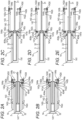
Figs. 2A to 2E are schematic views for describing a structure and an extension and retraction operation of a telescopic boom. -
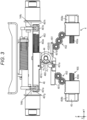
Fig. 3 is a front view of a pin movement module in an extended state and in a state of holding boom coupling pins. -
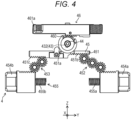
Fig. 4 is a front view of the pin movement module in which a boom coupling mechanism is in a retracted state and a cylinder coupling mechanism is in an extended state. -
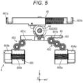
Fig. 5 is a front view of the pin movement module in which the boom coupling mechanism is in an extended state and the cylinder coupling mechanism is in a retracted state. -
Fig. 6A is a circuit diagram of an electric circuit in a first driving state. -
Fig. 6B is a circuit diagram of an electric circuit in a second driving state. -
Fig. 6C is a circuit diagram of an electric circuit in a first release state. -
Fig. 6D is a circuit diagram of an electric circuit in a second release state. -
Fig. 6E is a circuit diagram of an electric circuit in a braking state. -
Fig. 7A is a schematic view for describing an operation of the cylinder coupling mechanism. -
Fig. 7B is a schematic view for describing the operation of the cylinder coupling mechanism. -
Fig. 7C is a schematic view for describing the operation of the cylinder coupling mechanism. -
Fig. 8A is a schematic view for describing an operation of the boom coupling mechanism. -
Fig. 8B is a schematic view for describing the operation of the boom coupling mechanism. -
Fig. 8C is a schematic view for describing the operation of the boom coupling mechanism. - Hereinafter, an example of embodiments according to the present invention will be described in detail based on the drawings. Note that a crane according to the embodiment described below is an example of a work machine according to the present invention, and the present invention is not limited to the embodiments described below.
-
Fig. 1 is a schematic view of a mobile crane 1 (in the illustrated case, rough terrain crane) according to the present embodiment. Themobile crane 1 corresponds to an example of a work machine. - Examples of the mobile crane include an all-terrain crane, a truck crane, and a loading truck crane (also referred to as a cargo crane). However, the work machine according to the present invention is not limited to a mobile crane and may be any other work machine (for example, a crane, or a high place work vehicle) including a telescopic boom.
- As illustrated in
Figs. 1 and2A to 2E , themobile crane 1 according to the present embodiment includes atelescopic boom 14 and anactuator 2 that extends and retracts thetelescopic boom 14. - The
telescopic boom 14 has a telescopically combined boom (distal end boom 141,intermediate boom 142, and proximal end boom 143). The adjacent booms are connected by a boom coupling pin (boom coupling pins - The
actuator 2 moves the boom in the extending and retracting direction when extending and retracting thetelescopic boom 14. At this time, theactuator 2 is connected to the boom to be moved via thecylinder coupling pins actuator 2 moves the boom. - In the extension and retraction operation of the
telescopic boom 14, when the movement time of the above-described boom coupling pin (boom coupling pins cylinder coupling pins mobile crane 1 according to the present embodiment has a function for shortening the movement time of the boom coupling pin (boom coupling pins cylinder coupling pins telescopic boom 14. In themobile crane 1 according to the present embodiment, this function is realized by anelectric circuit 6 and acontrol unit 47 to be described later. Hereinafter, the configuration of themobile crane 1 according to the present embodiment will be specifically described. - As illustrated in
Fig. 1 ,mobile crane 1 includes a travelingbody 10, anoutrigger 11, a turning table 12, thetelescopic boom 14, the actuator 2 (not illustrated inFig. 1 ), the electric circuit 6 (refer toFigs. 6A to 6E ), a raising and loweringcylinder 15, awire rope 16, and ahook 17. - The traveling
body 10 has a plurality ofwheels 101. Theoutriggers 11 are provided at four corners of the travelingbody 10. The turning table 12 is rotatably provided on the upper part of the travelingbody 10. A proximal end portion of thetelescopic boom 14 is fixed to the turning table 12. Theactuator 2 extends and retracts thetelescopic boom 14. The raising and loweringcylinder 15 raises and lowers thetelescopic boom 14. Thewire rope 16 is supported by thetelescopic boom 14 and hangs down from a distal end portion of thetelescopic boom 14. Thehook 17 is provided at the tip of thewire rope 16. - Subsequently, the
telescopic boom 14 will be described with reference toFigs. 1 and2A to 2E. Figs. 2A to 2E are schematic views for describing a structure and an extension and retraction operation of thetelescopic boom 14. - The
telescopic boom 14 includes a plurality of booms. Each of the plurality of booms has a cylindrical shape. The plurality of booms are combined with each other in a telescopic manner. Specifically, in the retracted state, the plurality of booms are thedistal end boom 141, theintermediate boom 142, and theproximal end boom 143 in order from inside. - Furthermore, the
distal end boom 141 and theintermediate boom 142 are booms movable in the extending and retracting direction. Theproximal end boom 143 is a boom whose movement in the extending and retracting direction is restricted. - The
telescopic boom 14 extends the boom in order from the boom disposed inside (namely, the distal end boom 141) to make a state transition from the retracted state illustrated inFig. 2A to the extended state illustrated inFig. 1 . - In the extended state, the
intermediate boom 142 is disposed between theproximal end boom 143 on the most proximal end side and thedistal end boom 141 on the most distal end side. A plurality of intermediate booms may be provided. - The structure of the
telescopic boom 14 is substantially the same as a telescopic boom known from the related art; however, for convenience of describing the structure and the operation of theactuator 2 to be described later, hereinafter, structures of thedistal end boom 141 and theintermediate boom 142 will be described. - The
distal end boom 141 has a cylindrical shape and has an internal space where theactuator 2 can be accommodated. Thedistal end boom 141 includes a pair of cylinderpin receiving portions 141a and a pair of boompin receiving portions 141b in the proximal end portion. - The pair of cylinder
pin receiving portions 141a are coaxially provided in the proximal end portion of thedistal end boom 141. Each of the pair of cylinderpin receiving portions 141a can be engaged with and disengaged from the pair ofcylinder coupling pins cylinder member 32 of the extension/retraction cylinder 3. The pair ofcylinder coupling pins - The
cylinder coupling pins cylinder coupling pins first biasing mechanism 455 to be described later. Thecylinder coupling pins cylinder coupling mechanism 45 provided in theactuator 2 to be described later. In a state where the pair ofcylinder coupling pins pin receiving portions 141a are engaged with each other, thedistal end boom 141 can be moved together with thecylinder member 32 in the extending and retracting direction. - The pair of boom
pin receiving portions 141b are coaxially provided closer to the proximal end side than the cylinderpin receiving portions 141a. The boompin receiving portions 141b are engaged with and disengaged from a pair ofboom coupling pins 144a, respectively. The pair ofboom coupling pins 144a corresponds to an example of a first pin. - The pair of
boom coupling pins 144a is respectively biased in the first direction in the axial direction of theboom coupling pins 144a by asecond biasing mechanism 463 to be described later. The pair ofboom coupling pins 144a connects thedistal end boom 141 and theintermediate boom 142, respectively. - The pair of
boom coupling pins 144a are moved in the second direction in their own axial direction based on the operation of aboom coupling mechanism 46 provided in theactuator 2. The pair ofboom coupling pins 144a may be regarded as constituent members of theboom coupling mechanism 46. - In a state where the
distal end boom 141 and theintermediate boom 142 are connected by the pair ofboom coupling pins 144a, theboom coupling pins 144a are inserted through the boompin receiving portions 141b of thedistal end boom 141 and a first boompin receiving portion 142b or a second boompin receiving portion 142c of theintermediate boom 142 to be described later in a bridging manner. - In the state where the
distal end boom 141 and theintermediate boom 142 are connected (also referred to as a connected state), thedistal end boom 141 is prohibited from moving in the extending and retracting direction with respect to theintermediate boom 142. - Meanwhile, in a state where the connection between the
distal end boom 141 and theintermediate boom 142 is released (also referred to as a non-connected state), thedistal end boom 141 can be moved in the extending and retracting direction with respect to theintermediate boom 142. - The
intermediate boom 142 has a cylindrical shape and has an internal space where thedistal end boom 141 can be accommodated. Theintermediate boom 142 includes a pair of cylinderpin receiving portions 142a, a pair of first boompin receiving portions 142b, a pair of second boompin receiving portions 142c, and a pair of third boompin receiving portions 142d in the proximal end portion. - The pair of cylinder
pin receiving portions 142a and the pair of first boompin receiving portions 142b are substantially the same as the pair of cylinderpin receiving portions 141a and the pair of boompin receiving portions 141b that thedistal end boom 141 includes, respectively. - The pair of third boom
pin receiving portions 142d are coaxially provided closer to the proximal end side than the pair of first boompin receiving portions 142b. The pair of boom coupling pins 144b is inserted through the pair of third boompin receiving portions 142d, respectively. The pair of boom coupling pins 144b connects theintermediate boom 142 and theproximal end boom 143. - The pair of second boom
pin receiving portions 142c are coaxially provided in the distal end portion of theintermediate boom 142. The pair ofboom coupling pins 144a is inserted through the pair of second boompin receiving portions 142c, respectively. - Hereinafter, the
actuator 2 will be described with reference toFigs. 3 to 8C . Theactuator 2 is an actuator that extends and retracts thetelescopic boom 14. - The
actuator 2 includes the extension/retraction cylinder 3, apin movement module 4, andcontrol unit 47. In the retracted state (state illustrated inFig. 2A ) of thetelescopic boom 14, theactuator 2 is disposed in the internal space of thedistal end boom 141. - The extension/
retraction cylinder 3 includes a rod member 31 (also referred to as a fixed side member, and refer toFigs. 2A to 2E ) and a cylinder member 32 (also referred to as a movable side member.). The extension/retraction cylinder 3 moves the boom (for example, thedistal end boom 141 or the intermediate boom 142), which is connected to thecylinder member 32, in the extending and retracting direction via thecylinder coupling pins - The
pin movement module 4 includes a housing (not illustrated), anelectric motor 41, abrake mechanism 42, atransmission mechanism 43, a positioninformation detection device 44, thecylinder coupling mechanism 45, theboom coupling mechanism 46. - Hereinafter, each member forming the
actuator 2 will be described based on a state where each member is assembled in theactuator 2. In addition, in the description of theactuator 2, an orthogonal coordinate system (X, Y, Z) illustrated in each drawing will be used. However, the disposition of each part forming theactuator 2 is not limited to the disposition in the present embodiment. Further, the configuration of theactuator 2 may be omitted as long as it is not technically inconsistent. In other words, theactuator 2 may be configured by a combination of configurations arbitrarily selected from each configuration described later within a technically consistent range. - In the orthogonal coordinate system illustrated in each drawing, an X-direction coincides with the extending and retracting direction of the
telescopic boom 14 in the state of being installed in themobile crane 1. An X-direction positive side is also referred to as an extending direction in the extending and retracting direction. An X-direction negative side is also referred to as a retracting direction in the extending and retracting direction. Further, a Z-direction coincides with the vertical direction of themobile crane 1, for example, in a state where the raising and lowering angle of thetelescopic boom 14 is 0 (also referred to as a fallen state of thetelescopic boom 14.). A Y-direction coincides with the vehicle width direction of themobile crane 1, for example, in a state where thetelescopic boom 14 faces forward. However, the Y-direction and the Z-direction are not limited to the above-described directions as long as the Y-direction and the Z-direction are two directions orthogonal to each other. - The housing (not illustrated) is fixed to the
cylinder member 32 of the extension/retraction cylinder 3. Thecylinder coupling mechanism 45 to be described later and theboom coupling mechanism 46 are accommodated in an internal space of the housing. The housing supports theelectric motor 41, thebrake mechanism 42, and thetransmission mechanism 43 to be described later. - Such a housing unitizes each of the above-described elements. Such a configuration contributes to reduction in size of the
pin movement module 4, improvement in productivity, and improvement in system reliability. - The
rod member 31 of the extension/retraction cylinder 3 is inserted through a part of the housing in the X-direction. The proximal end portion (end portion on the negative side in the X-direction) of thecylinder member 32 of the extension/retraction cylinder 3 is fixed to a sidewall on the positive side in the X-direction of the housing. - The housing has first through-holes (not illustrated) in sidewalls on both sides in the Y-direction. The pair of
cylinder coupling pins cylinder coupling mechanism 45 are inserted through the first through-holes, respectively. - A transmission shaft 432 (refer to
Fig. 3 ) of thetransmission mechanism 43 to be described later is inserted through a part of the housing in the X-direction. - The housing has second through-holes (not illustrated) in sidewalls on both sides in the Y-direction. A pair of
second rack bars boom coupling mechanism 46 are inserted through the second through-holes, respectively. - The
electric motor 41 is supported on the housing via aspeed reducer 431 of thetransmission mechanism 43. Specifically, in a state where an output shaft (not illustrated) is parallel with the X-direction, theelectric motor 41 is disposed around the cylinder member 32 (for example, on the Z-direction positive side) and around the housing (for example, on the X-direction negative side or the Z-direction positive side). Such disposition contributes to reduction in size of thepin movement module 4 in the Y-direction and the Z-direction. - The
electric motor 41 as described above is connected to, for example, a power supply device 61 (refer toFigs. 6A to 6E ) provided on the turning table 12 via a power supply cable. - Each of the above-described cables can be released and wound by a cord reel provided on the outside of the proximal end portion of the
telescopic boom 14 or in the turning table 12 (refer toFig. 1 ). - The number of electric motors may be one or plural (for example, two). When there is one electric motor, as in the present embodiment, the
cylinder coupling mechanism 45 and theboom coupling mechanism 46 are operated by oneelectric motor 41. When there are a plurality of (for example, two) electric motors, the first electric motor (not illustrated) may operate thecylinder coupling mechanism 45, and the second electric motor (not illustrated) may operate theboom coupling mechanism 46. - The
brake mechanism 42 applies a braking force to theelectric motor 41. Thebrake mechanism 42 prevents the rotation of the output shaft of theelectric motor 41 in a state where theelectric motor 41 is stopped. Accordingly, in a state where theelectric motor 41 is stopped, the state of thepin movement module 4 is maintained. - The
brake mechanism 42 is connected to, for example, the power supply device (not illustrated) provided on the turning table 12 via a power supply cable. Note that a positioninformation detection device 44 to be described later is also connected to, for example, the power supply device (not illustrated) provided on the turning table 12 via the power supply cable. Furthermore, the positioninformation detection device 44 is connected to a control unit (not illustrated) provided on the turning table 12 via a signal transmission cable. The power supply cable to theelectric motor 41, the power supply cable to thebrake mechanism 42, the power supply cable to the positioninformation detection device 44, and the signal transmission cable of the positioninformation detection device 44 are collectively arranged in the internal space of thetelescopic boom 14 as one multicore cable. With such a configuration, the internal space of thetelescopic boom 14 can be efficiently used. - Specifically, in a retracted state of the
cylinder coupling mechanism 45 to be described later or in a retracted state of theboom coupling mechanism 46, thebrake mechanism 42 operates to maintain the state of thecylinder coupling mechanism 45 or theboom coupling mechanism 46. - The
transmission mechanism 43 transmits power of theelectric motor 41 to thecylinder coupling mechanism 45 or theboom coupling mechanism 46. Thetransmission mechanism 43 includes thespeed reducer 431 and the transmission shaft 432 (refer toFig. 7A ). - The
speed reducer 431 reduces the rotation of theelectric motor 41 to transmit the reduced rotation to thetransmission shaft 432. Thespeed reducer 431 is, for example, a planetary gear mechanism. - A first end portion of the
transmission shaft 432 is connected to an output shaft (not illustrated) of thespeed reducer 431. Thetransmission shaft 432 rotates together with the output shaft of thespeed reducer 431. Thetransmission shaft 432 extends in the X-direction and is inserted through the housing (not illustrated) of thepin movement module 4. - The second end portion of the
transmission shaft 432 protrudes to the X-direction positive side from the housing. The positioninformation detection device 44 to be described later is provided in the end portion on the X-direction positive side of thetransmission shaft 432. - The position
information detection device 44 detects information on the positions of the pair ofcylinder coupling pins - The information on the position may be, for example, a movement amount of the pair of
cylinder coupling pins boom coupling pins 144a from the reference position (the position illustrated inFigs. 7A and8A ). The positions of the pair ofcylinder coupling pins Figs. 7A and8A are defined as reference positions of thecylinder coupling pins boom coupling pins 144a illustrated inFigs. 7A and8A are defined as reference positions of theboom coupling pins 144a. - The information on the positions of the pair of
cylinder coupling pins boom coupling pins 144a detected by the positioninformation detection device 44 is used for various controls of theactuator 2 including the control of theelectric motor 41. - The
cylinder coupling mechanism 45 operates based on the power of theelectric motor 41 and makes a state transition between the extended state (refer toFigs. 3 and4 ) and the retracted state (refer toFig. 5 ). The operation in which thecylinder coupling mechanism 45 transitions from the extended state to the retracted state is referred to as a removal operation of thecylinder coupling mechanism 45. The operation in which thecylinder coupling mechanism 45 transitions from the retracted state to the extended state is referred to as an entry operation of thecylinder coupling mechanism 45. - In the extended state, the pair of
cylinder coupling pins pin receiving portions 141a of a boom (for example, the distal end boom 141) enter the engaged state (also referred to as an entry state of a cylinder pin). In such an engaged state, the boom and thecylinder member 32 enter a connected state. That is, by the entry operation of thecylinder coupling mechanism 45, the pair ofcylinder coupling pins first biasing mechanism 455 to be described later. - Meanwhile, in the retracted state, the pair of
cylinder coupling pins pin receiving portions 141a (refer toFigs. 2A to 2E ) enter a disengaged state (the state illustrated inFig. 2E and also referred to as a removal state of a cylinder pin). In the disengaged state, the boom and thecylinder member 32 enter a non-connected state. - As illustrated in
Figs. 3 ,4 , and5 , thecylinder coupling mechanism 45 includes a first tooth-missing gear 450 (refer toFigs. 7A to 7C ), afirst rack bar 451, afirst gear mechanism 452, asecond gear mechanism 453, the pair ofcylinder coupling pins first biasing mechanism 455. - The first tooth-missing gear 450 (also referred to as a switch gear.) has a substantially disk shape. The first tooth-missing
gear 450 has a first tooth portion in a part of the outer peripheral surface. The first tooth-missinggear 450 is externally fitted and fixed to thetransmission shaft 432 to rotate together with thetransmission shaft 432. In the present embodiment, the first tooth-missinggear 450 is disposed so as to overlap a second tooth-missinggear 460 to be described later in the front-rear direction. Therefore, inFigs. 3 to 5 , the first tooth-missinggear 450 is not illustrated. - The first tooth-missing
gear 450 forms the switch gear, together with the second tooth-missing gear 460 (refer toFig. 3 ) of theboom coupling mechanism 46. The switch gear selectively transmits power of theelectric motor 41 to any one coupling mechanism of thecylinder coupling mechanism 45 and theboom coupling mechanism 46. - In the following description, when the
cylinder coupling mechanism 45 makes a state transition from the extended state (refer toFigs. 3 ,4 , and7A ) to the retracted state (refer toFigs. 5 and7C ), the rotation direction (direction indicated by arrow A1 inFigs. 7A to 7C ) of the first tooth-missinggear 450 is the first direction in the rotation direction of the first tooth-missinggear 450. - On the other hand, the rotation direction (direction indicated by arrow A2 in
Figs. 7A to 7C ) of the first tooth-missinggear 450 when thecylinder coupling mechanism 45 transitions from the retracted state to the extended state is the second direction in the rotation direction of the first tooth-missinggear 450. - The
first rack bar 451 is moved in a longitudinal direction (also referred to as the Y-direction) thereof according to the rotation of the first tooth-missinggear 450. In the extended state (refer toFigs. 3 and4 ), thefirst rack bar 451 is positioned on a Y-direction negative-most side. Meanwhile, in the retracted state (refer toFig. 5 ), thefirst rack bar 451 is positioned on a Y-direction positive-most side. - During a state transition from the extended state to the retracted state, when the first tooth-missing
gear 450 rotates in the first direction, thefirst rack bar 451 is moved to a Y-direction positive side (also referred to as one side in the longitudinal direction). - On the other hand, when the state transitions from the retracted state to the extended state, when the first tooth-missing
gear 450 rotates in the second direction, thefirst rack bar 451 is moved to the Y-direction negative side (also referred to as the other side in the longitudinal direction.). - The
first rack bar 451 includes a first rack tooth portion in a surface thereof, the surface being on a side (also referred to as the Z-direction positive side) close to the first tooth-missinggear 450. Only when the above-described state transition is made, the first rack tooth portion meshes with the first tooth portion of the first tooth-missinggear 450. - When the first tooth-missing
gear 450 rotates by a predetermined amount in the first direction in the extended state, the first tooth portion of the first tooth-missinggear 450 meshes with the first rack tooth portion of thefirst rack bar 451. When the first tooth-missinggear 450 further rotates in the first direction from this state, thefirst rack bar 451 is moved to the Y-direction positive side the according to the rotation of the first tooth-missinggear 450. - Furthermore, when the first tooth-missing
gear 450 rotates in the second direction from the extended state illustrated inFig. 3 , the first rack tooth portion of thefirst rack bar 451 and the first tooth portion of the first tooth-missinggear 450 do not mesh with each other. - In addition, the
first rack bar 451 includes a second rack tooth portion and a third rack tooth portion on a surface thereof, the surface being on a side (also referred to as a Z-direction negative side) distant from the first tooth-missinggear 450. The second rack tooth portion meshes with thefirst gear mechanism 452 to be described later. The third rack tooth portion meshes with thesecond gear mechanism 453 to be described later. - The
first gear mechanism 452 includes a plurality (in the case of the present embodiment, three) of gear elements (refer toFig. 3 ) of which each is a spur gear. Thefirst gear mechanism 452 meshes with the second rack tooth portion of thefirst rack bar 451. Thefirst gear mechanism 452 rotates in accordance with the movement of thefirst rack bar 451 in the Y-direction. In addition, thefirst gear mechanism 452 meshes with a pin-side rack tooth portion of onecylinder coupling pin 454a to be described later. - The
second gear mechanism 453 includes a plurality (in the case of the present embodiment, two) of gear elements (refer toFig. 3 ) of which each is a spur gear. Thesecond gear mechanism 453 meshes with the third rack tooth portion of thefirst rack bar 451. Thesecond gear mechanism 453 rotates in accordance with the movement of thefirst rack bar 451 in the Y-direction. In addition, thesecond gear mechanism 453 meshes with a pin-side rack tooth portion of the othercylinder coupling pin 454b to be described later. - Note that the number of gears constituting the
first gear mechanism 452 and thesecond gear mechanism 453 is not limited to the case of the present embodiment. From the viewpoint of moving onecylinder coupling pin 454a and the othercylinder coupling pin 454b in opposite directions to each other according to the movement of thefirst rack bar 451, the number of gears of thefirst gear mechanism 452 may be an odd number, and the number of gears of thesecond gear mechanism 453 may be an even number. - Further, the number of gears of the
first gear mechanism 452 and the number of gears of thesecond gear mechanism 453 may be determined by the relationship with the number of components of thepin movement module 4 and the dimension in the right-left direction (Y-direction). For example, if the number of gears of thefirst gear mechanism 452 is one, the number of parts can be reduced, but since it is necessary to match the positions in the Y-direction of the meshing portion between thefirst gear mechanism 452 and thefirst rack bar 451 and the meshing portion between thefirst gear mechanism 452 and thecylinder coupling pin 454a, the dimension of thefirst rack bar 451 in the Y-direction increases. On the other hand, as in the present embodiment, if the number of gears of thefirst gear mechanism 452 is three, the number of parts increases, but since the meshing portion between thefirst gear mechanism 452 and thefirst rack bar 451 can be positioned on the left side (Y-direction negative side) of the meshing portion between thefirst gear mechanism 452 and thecylinder coupling pin 454a, the dimension of thefirst rack bar 451 in the Y-direction can be reduced. - The pair of
cylinder coupling pins cylinder coupling pins cylinder coupling pin 454a meshes with thefirst gear mechanism 452. - One
cylinder coupling pin 454a is moved in its own axial direction in accordance with the rotation of thefirst gear mechanism 452. Specifically, onecylinder coupling pin 454a is moved to the Y-direction positive side (also referred to as the second direction.) when transitioning from the retracted state to the extended state. Meanwhile, onecylinder coupling pin 454a is moved to the Y-direction negative side (also referred to as the first direction.) when transitioning from the extended state to the retracted state. - The pin-side rack tooth portion of the other (also referred to as the Y-direction negative side)
cylinder coupling pin 454b meshes with thesecond gear mechanism 453. - The other
cylinder coupling pin 454b is moved in its own axial direction in accordance with the rotation of thesecond gear mechanism 453. Specifically, the othercylinder coupling pin 454b is moved to the Y-direction negative side (also referred to as the second direction.) when transitioning from the retracted state to the extended state. Meanwhile, the othercylinder coupling pin 454b is moved to the Y-direction positive side (also referred to as the first direction.) when transitioning from the extended state to the retracted state. In the above-described state transition, the pair ofcylinder coupling pins - The pair of
cylinder coupling pins cylinder coupling pins - The
first biasing mechanism 455 corresponds to an example of a biasing portion and a first biasing member and returns thecylinder coupling mechanism 45 to the extended state when theelectric motor 41 is in a non-energized state in the retracted state of thecylinder coupling mechanism 45. In other words, thefirst biasing mechanism 455 returns the pair ofcylinder coupling pins electric motor 41 is in the non-energized state (stopped state) in the retracted state of thecylinder coupling mechanism 45. Thefirst biasing mechanism 455 biases the pair ofcylinder coupling pins - In other words, the
first biasing mechanism 455 biases the pair ofcylinder coupling pins cylinder coupling pins cylinder coupling pin 454a and the first direction in the axial direction of thecylinder coupling pin 454b are opposite directions with respect to the Y-direction. - Further, the
first biasing mechanism 455 may directly bias thecylinder coupling pins - Specifically, the
first biasing mechanism 455 includes configured with a pair ofcoil springs Fig. 3 ). Each of the pair ofcoil springs cylinder coupling pins cylinder coupling pins brake mechanism 42 is in operation, thecylinder coupling mechanism 45 does not transition from the retracted state to the extended state. - The
boom coupling mechanism 46 transitions between an extended state (refer toFigs. 3 and5 ) and a retracted state (refer toFig. 4 ) based on the rotation of theelectric motor 41. The operation in which theboom coupling mechanism 46 transitions from the extended state to the retracted state is referred to as a removal operation of theboom coupling mechanism 46. The operation in which theboom coupling mechanism 46 transitions from the retracted state to the extended state is referred to as an entry operation of theboom coupling mechanism 46. - In the extended state, the
boom coupling mechanism 46 can take either an engaged state or the disengaged state with respect to boom coupling pins (for example, the pair ofboom coupling pins 144a). - In a state where the
boom coupling mechanism 46 is engaged with boom coupling pins, theboom coupling mechanism 46 makes a state transition from the extended state to the retracted state to cause the boom coupling pins to disengage from the boom. - In addition, in a state where the
boom coupling mechanism 46 is engaged with the boom coupling pins, theboom coupling mechanism 46 makes a state transition from the retracted state to the extended state to cause the boom coupling pins to engage with the boom. That is, the boom coupling pin returns to the reference position by thesecond biasing mechanism 463 to be described later by the entry operation of theboom coupling mechanism 46. - As illustrated in
Fig. 3 , theboom coupling mechanism 46 includes a second tooth-missinggear 460, the pair ofsecond rack bars Figs. 8A to 8C ), and asecond biasing mechanism 463. - The second tooth-missing gear 460 (also referred to as a switch gear) has a substantially disk shape and includes a second tooth portion in a part of an outer peripheral surface thereof in a circumferential direction.
- The second tooth-missing
gear 460 is externally fitted and fixed to a portion closer to the X-direction positive side in thetransmission shaft 432 than the first tooth-missinggear 450, to rotate together with thetransmission shaft 432. The second tooth-missinggear 460 may be a tooth-missing gear integrated with the first tooth-missinggear 450. - Hereinafter, the rotation direction of the second tooth-missing gear 460 (direction indicated by arrow A2 in
Figs. 3 and8A to 8C ) when theboom coupling mechanism 46 transitions from the extended state (refer toFigs. 3 and5 ) to the retracted state (refer toFig. 4 ) is the first direction in the rotation direction of the second tooth-missinggear 460. - On the other hand, the rotation direction of the second tooth-missing gear 460 (direction indicated by arrow A1 in
Figs. 3 and8A to 8C ) when theboom coupling mechanism 46 transitions from the retracted state to the extended state is the second direction in the rotation direction of the second tooth-missinggear 460. -
Fig. 3 is a view of thepin movement module 4 as seen from the X-direction positive side. Therefore, in the case of the present embodiment, the first direction and the second direction in the rotation direction of the second tooth-missinggear 460 are opposite to the first direction and the second direction in the rotation direction of the first tooth-missinggear 450. - Namely, the rotation direction of the second tooth-missing
gear 460 when theboom coupling mechanism 46 makes a state transition from the extended state to the retracted state is reversed to the rotation direction of the first tooth-missinggear 450 when thecylinder coupling mechanism 45 makes a state transition from the extended state to the retracted state. - As the second tooth-missing
gear 460 rotates, each of the pair ofsecond rack bars second rack bars 461a and the other (X-direction negative side) of the second rack bars 461b are moved in opposite directions in the Y-direction. - Each of the pair of
second rack bars second rack bars first rack bar 451. - Each of the pair of
second rack bars synchronous gear 462. When thesynchronous gear 462 rotates, the onesecond rack bar 461a and the othersecond rack bar 461b are moved in opposite directions in the Y-direction. - Each of the pair of
second rack bars claw portions claw portions side receiving portions 144c (refer toFig. 3 ) provided in the boom coupling pin when the boom coupling pin (for example,boom coupling pins - One of the
second rack bars 461a has a driving rack tooth portion 461c (refer toFig. 3 ) on a side surface facing the second tooth-missinggear 460. The driving rack tooth portion 461c meshes with the second tooth portion of the second tooth-missinggear 460. - When the second tooth-missing
gear 460 rotates by a predetermined amount in the first direction from the extended state, the driving rack tooth portion 461c meshes with the second tooth portion of the second tooth-missinggear 460. When the second tooth-missinggear 460 further rotates in the first direction, one of thesecond rack bars 461a is moved to the Y-direction positive side based on the meshing between the driving rack tooth portion 461c and the second tooth portion of the second tooth-missinggear 460. - Furthermore, when the one
second rack bar 461a is moved to the Y-direction positive side, thesynchronous gear 462 rotates, so that the othersecond rack bar 461b is moved to the Y-direction negative side (namely, opposite side from the onesecond rack bar 461a). - The
second biasing mechanism 463 corresponds to an example of the biasing portion and the second biasing member, and returns theboom coupling mechanism 46 to the extended state when theelectric motor 41 is in the non-energized state in the retracted state of theboom coupling mechanism 46. In other words, thesecond biasing mechanism 463 returns the boom coupling pin (for example, the pair ofboom coupling pins 144a) to the reference position when theelectric motor 41 is in the non-energized state (stopped state) in the retracted state of thesecond biasing mechanism 463. Further, when thebrake mechanism 42 is in operation, theboom coupling mechanism 46 does not transition from the retracted state to the extended state. - The
second biasing mechanism 463 biases the pair ofsecond rack bars second biasing mechanism 463 indirectly biases the boom coupling pin in the first direction in the axial direction of the boom coupling pin via the pair ofsecond rack bars boom coupling mechanism 46 and the boom coupling pin (for example, a pair ofboom coupling pins 144a) are engaged with each other. - Specifically, the
second biasing mechanism 463 is configured by a pair ofcoil springs Fig. 8A ). Each of the pair ofcoil springs second rack bars - The
control unit 47 is, for example, an in-vehicle computer (processor) configured with an input terminal, an output terminal, a CPU, a memory, and the like. The function of thecontrol unit 47 may be realized by a control circuit. - The
control unit 47 as described above is mounted on the mobile crane 1 (Specifically, the turning table 12). However, the position of thecontrol unit 47 is not limited to the turning table 12. Thecontrol unit 47 controls switches 62 to 66 of theelectric circuit 6 to be described later. A specific function of thecontrol unit 47 will be described later together with the configuration of theelectric circuit 6. - Next, the
electric circuit 6 will be described with reference toFigs. 6A to 6E . Theelectric circuit 6 realizes a plurality of states by switching the switches under the control of thecontrol unit 47. A plurality of states realized by theelectric circuit 6 will be described later. - The
electric circuit 6 includes thepower supply device 61, afirst switch 62, asecond switch 63, athird switch 64, afourth switch 65, afifth switch 66, and theelectric motor 41. - The
power supply device 61 is provided, for example, on the turning table 12 (refer toFig. 1 ). - The
first switch 62 is provided on a first line 6L1. Thefirst switch 62 can take either an ON state or an OFF state under the control of the control unit 47 (refer toFig. 1 ). - The
second switch 63 is provided in series with thefirst switch 62 on the first line 6L1. Thesecond switch 63 is provided on the downstream side of thefirst switch 62 in the direction in which the current flows in the first line 6L1. Thesecond switch 63 can take either an ON state or an OFF state under the control of thecontrol unit 47. - The
first switch 62 and thesecond switch 63 are configured by afirst relay circuit 681. Thefirst relay circuit 681 turns on one of thefirst switch 62 and thesecond switch 63 and turns off the other switch based on a command signal from thecontrol unit 47. - The
third switch 64 is provided on a second line 6L2. The second line 6L2 is provided in parallel with the first line 6L1. Thethird switch 64 can take either an ON state or an OFF state under the control of thecontrol unit 47. - The
fourth switch 65 is provided in series with thethird switch 64 on the second line 6L2. Thefourth switch 65 is provided on the downstream side (hereinafter, it is simply referred to as a "downstream side".) of thethird switch 64 in the direction in which the current flows in the second line 6L2. Thefourth switch 65 can take either an ON state or an OFF state under the control of thecontrol unit 47. - The
third switch 64 and thefourth switch 65 are configured by asecond relay circuit 682. Thesecond relay circuit 682 turns on one of thethird switch 64 and thefourth switch 65 and turns off the other switch based on a command signal from thecontrol unit 47. - The
fifth switch 66 is configured by athird relay circuit 683 and is provided on a third line 6L3. The third line 6L3 is provided in series with the first line 6L1 and the second line 6L2 on the downstream side of the first line 6L1 and the second line 6L2. The fifth switch 66 (the third relay circuit 683) can take either an ON state or an OFF state under the control of thecontrol unit 47. - The configuration of the
electric motor 41 is as described above. Theelectric motor 41 is provided on a fourth line 6L4. The fourth line 6L4 connects a portion between thefirst switch 62 and thesecond switch 63 in the first line 6L1 and a portion between thethird switch 64 and thefourth switch 65 in the second line 6L2. - The above-described
electric circuit 6 can take the first driving state illustrated inFig. 6A , the second driving state illustrated inFig. 6B , a first release state illustrated inFig. 6C , a second release state illustrated inFig. 6D , and a braking state illustrated inFig. 6E . - The first driving state of the
electric circuit 6 corresponds to a first state of theelectric circuit 6, and is a state in which a current in a first direction flows through theelectric motor 41 as illustrated inFig. 6A . The first direction is a direction from the first line 6L1 to the second line 6L2 in the fourth line 6L4. In the first driving state of theelectric circuit 6, the current flows through a circuit indicated by a thick line inFig. 6A . - In the first driving state of the
electric circuit 6, theelectric motor 41 rotates in the first direction. In the first driving state of theelectric circuit 6, thefirst switch 62, thefourth switch 65, and thefifth switch 66 are in an ON state. In the first driving state of theelectric circuit 6, thesecond switch 63 and thethird switch 64 are in an OFF state. The first driving state corresponds to an example of a driving state of the electric circuit. - The first driving state of the
electric circuit 6 is a state for causing thecylinder coupling mechanism 45 to transition from the extended state to the retracted state (removal operation of the cylinder coupling mechanism 45). Thecontrol unit 47 switches theelectric circuit 6 to the first driving state in a case where the removal operation of thecylinder coupling mechanism 45 is realized. - The second driving state of the
electric circuit 6 corresponds to a second state of theelectric circuit 6, and is a state in which a current in a second direction flows through theelectric motor 41 as illustrated inFig. 6B . The second direction is a direction from the second line 6L2 toward the first line 6L1 in the fourth line 6L4. In the second driving state of theelectric circuit 6, the current flows through the circuit indicated by a thick line inFig. 6B . - In the second driving state of the
electric circuit 6, theelectric motor 41 rotates in the second direction. In the second driving state of theelectric circuit 6, thesecond switch 63, thethird switch 64, and thefifth switch 66 are in an ON state. In the second driving state of theelectric circuit 6, thefirst switch 62 and thefourth switch 65 are in an OFF state. - The second driving state of the
electric circuit 6 is a state for causing theboom coupling mechanism 46 to transition from the extended state to the retracted state (removal operation of the boom coupling mechanism 46). Thecontrol unit 47 switches theelectric circuit 6 to the second driving state in a case where the removal operation of theboom coupling mechanism 46 is realized. - The first release state of the
electric circuit 6 corresponds to an example of a third state of theelectric circuit 6, and is a state (non-driving state) in which no current flows through theelectric motor 41 as illustrated inFig. 6C . - In the first release state of the
electric circuit 6, thefirst switch 62 and thefourth switch 65 are in an ON state. Further, in the first release state of theelectric circuit 6, thesecond switch 63, thethird switch 64, and thefifth switch 66 are in an OFF state. That is, in the first release state of theelectric circuit 6, thesecond switch 63 provided in a closed circuit 67 (the circuit indicated by the thick line inFig. 6E ) including theelectric motor 41 is opened (turned into the OFF state). - The
control unit 47 switches theelectric circuit 6 to the first release state when thecylinder coupling mechanism 45 makes a state transition (an entry operation of the cylinder coupling mechanism 45) from the retracted state to the extended state. In other words, thecontrol unit 47 switches theelectric circuit 6 to the first release state when the pair ofcylinder coupling pins first biasing mechanism 455. Note that the instruction for causing the entry operation of thecylinder coupling mechanism 45 may be, for example, an instruction based on an operation input from an operator or an instruction based on a program incorporated in advance in thecontrol unit 47. - In the first release state of the
electric circuit 6, a closed circuit including theelectric motor 41 is not formed in theelectric circuit 6. Hereinafter, the reason for adopting such a configuration will be described. - In the entry operation of the
cylinder coupling mechanism 45, when theelectric circuit 6 is in the first release state and thebrake mechanism 42 is in the release state, the pair ofcylinder coupling pins first biasing mechanism 455. Then, as the pair ofcylinder coupling pins gear 450 rotates in the direction of arrow A2 inFig. 7C . - Then, the
electric motor 41 idles based on the rotation of the first tooth-missinggear 450. At this time, as illustrated inFig. 6E , when the closed circuit 67 (a circuit indicated by a thick line inFig. 6E ) including theelectric motor 41 is formed in theelectric circuit 6, theelectric motor 41 generates an electromotive force based on its own idling. - The current generated by the
electric motor 41 passes through theclosed circuit 67 and returns to theelectric motor 41. Then, a Lorentz force is generated in theelectric motor 41 based on the current returned to theelectric motor 41. The Lorentz force acts as a braking force on theelectric motor 41. Note that the above-described current is converted into thermal energy by a resistor (not illustrated) provided in theclosed circuit 67. Such a braking force also acts on the first tooth-missinggear 450 as a resistance force against the rotation of the first tooth-missinggear 450. - As described above, when the
closed circuit 67 is formed in theelectric circuit 6, the moving speed of the pair ofcylinder coupling pins cylinder coupling mechanism 45 becomes long, and the work efficiency may be lowered. - Therefore, in the case of the present embodiment, the
control unit 47 switches theswitches 62 to 66 of theelectric circuit 6 so that theclosed circuit 67 is not formed in theelectric circuit 6 in the entry operation of the cylinder coupling mechanism 45 (In other words, when the pair ofcylinder coupling pins cylinder coupling mechanism 45, when theelectric motor 41 idles, no current flows through theelectric motor 41. As a result, the generation of the above-described braking force can be suppressed in the entry operation of thecylinder coupling mechanism 45. As a result, the time required for the entry operation of thecylinder coupling mechanism 45 is shortened, and the work efficiency may be improved. - Note that the
control unit 47 may set the state of theelectric circuit 6 to the first release state in all processes from the start to the end of the entry operation of thecylinder coupling mechanism 45. However, thecontrol unit 47 may bring theelectric circuit 6 into the first release state from the start of the entry operation of thecylinder coupling mechanism 45 until the entry operation of thecylinder coupling mechanism 45 satisfies a predetermined condition. - Thereafter, the
control unit 47 may set the state of theelectric circuit 6 as illustrated inFig. 6E (braking state) until the entry operation of thecylinder coupling mechanism 45 is ended after the predetermined condition is satisfied. - In the braking state of the
electric circuit 6, thefirst switch 62 and thethird switch 64 are in an OFF state. In the braking state of theelectric circuit 6, thesecond switch 63 and thefourth switch 65 are in an ON state. In the braking state of theelectric circuit 6, thefifth switch 66 may be in an ON state or an OFF state. The braking state of theelectric circuit 6 means a state in which a closed circuit including theelectric motor 41 is formed in theelectric circuit 6. - The predetermined condition corresponds to, for example, a case where the moving distance of the pair of
cylinder coupling pins control unit 47 brings theelectric circuit 6 into the first release state when the moving distance of thecylinder coupling pins cylinder coupling mechanism 45. Thereafter, thecontrol unit 47 sets the state of theelectric circuit 6 as illustrated inFig. 6E (braking state) from when the moving distance of thecylinder coupling pins cylinder coupling mechanism 45 is ended. - As described above, in the braking state of the
electric circuit 6, the braking force acts on the first tooth-missinggear 450. As a result, the first tooth-missinggear 450 can be easily stopped at a desired position (reference position). - The second release state of the
electric circuit 6 corresponds to an example of the third state of theelectric circuit 6, and is a state (non-driving state) in which no current flows through theelectric motor 41 as illustrated inFig. 6D . - In the second release state of the
electric circuit 6, thesecond switch 63 and thethird switch 64 are in an ON state. Further, in the second release state of theelectric circuit 6, thefirst switch 62, thefourth switch 65, and thefifth switch 66 are in an OFF state. That is, in the second release state of theelectric circuit 6, thefourth switch 65 provided in the closed circuit 67 (the circuit indicated by the thick line inFig. 6E ) including theelectric motor 41 is opened (turned into the OFF state). - The
control unit 47 switches theelectric circuit 6 to the second release state when theboom coupling mechanism 46 makes a state transition (the entry operation of the boom coupling mechanism 46) from the retracted state to the extended state. In other words, when the boom coupling pin (For example, the pair ofboom coupling pins 144a) is moved by the biasing force received from thesecond biasing mechanism 463, thecontrol unit 47 switches theelectric circuit 6 to the second release state. Note that the instruction for causing the entry operation of theboom coupling mechanism 46 may be, for example, an instruction based on an operation input from an operator or an instruction based on a program incorporated in advance in thecontrol unit 47. - In the second release state of the
electric circuit 6, a closed circuit including theelectric motor 41 is not formed in theelectric circuit 6. Hereinafter, the reason for adopting such a configuration will be described. - In the entry operation of the
boom coupling mechanism 46, when theelectric circuit 6 is in the second release state and thebrake mechanism 42 is in the release state, the pair of boom coupling pins (for example, the pair ofboom coupling pins 144a) is moved in the first direction in the axial direction based on the biasing force of thesecond biasing mechanism 463. Then, as the boom coupling pin is moved, the second tooth-missinggear 460 rotates in the direction of arrow A1 inFig. 8C . - Then, the
electric motor 41 idles based on the rotation of the second tooth-missinggear 460. At this time, when the closed circuit 67 (refer toFig. 6E ) is formed in theelectric circuit 6 for the same reason as described in the first release state of theelectric circuit 6, the moving speed of the boom coupling pin in the first direction is reduced due to the braking force. - Therefore, in the case of the present embodiment, the
control unit 47 switches theswitches 62 to 66 of theelectric circuit 6 so that theclosed circuit 67 is not formed in theelectric circuit 6 in the entry operation of the boom coupling mechanism 46 (In other words, when the pair ofboom coupling pins 144a returns.). Therefore, in the entry operation of theboom coupling mechanism 46, when theelectric motor 41 idles, no current flows through theelectric motor 41. As a result, the generation of the above-described braking force can be suppressed in the entry operation of theboom coupling mechanism 46. As a result, the time required for the entry operation of theboom coupling mechanism 46 is shortened, and the work efficiency may be improved. - Note that the
control unit 47 may set the state of theelectric circuit 6 to the second release state in all processes from the start to the end of the entry operation of theboom coupling mechanism 46. However, thecontrol unit 47 may bring theelectric circuit 6 into the second release state from the start of the entry operation of theboom coupling mechanism 46 until the entry operation of theboom coupling mechanism 46 satisfies a predetermined condition. Thereafter, thecontrol unit 47 may set the state of theelectric circuit 6 to the braking state as illustrated inFig. 6E until the entry operation of theboom coupling mechanism 46 is ended after the predetermined condition is satisfied. - As described above, in the braking state of the
electric circuit 6, the above-described braking force acts on the second tooth-missinggear 460. As a result, the second tooth-missinggear 460 can be easily stopped at a desired position (reference position). - Hereinafter, an example of the operations of the above-described
cylinder coupling mechanism 45 and theboom coupling mechanism 46 will be briefly described. - First, an example of the operation of the
cylinder coupling mechanism 45 will be described with reference toFigs. 2A to 2E andFigs. 7A to 7C . -
Fig. 7A is a schematic view illustrating the extended state of thecylinder coupling mechanism 45 and the engaged state between the pair ofcylinder coupling pins pin receiving portions 141a of thedistal end boom 141.Fig. 7B is a schematic view illustrating a state in the middle of transition from the extended state to the retracted state of thecylinder coupling mechanism 45. Further,Fig. 7C is a schematic view illustrating the retracted state of thecylinder coupling mechanism 45 and the disengaged state between the pair ofcylinder coupling pins pin receiving portions 141a of thedistal end boom 141. - The extended state of the
cylinder coupling mechanism 45 illustrated inFig. 7A corresponds to the state of thecylinder coupling mechanism 45 inFigs. 2A to 2D . The state of thecylinder coupling mechanism 45 illustrated inFig. 7B corresponds to a state in the middle of transition from the state of thecylinder coupling mechanism 45 illustrated inFig. 2D to the state of thecylinder coupling mechanism 45 illustrated inFig. 2E . The retracted state of thecylinder coupling mechanism 45 illustrated inFig. 7C corresponds to the state of thecylinder coupling mechanism 45 illustrated inFig. 2E . - The
cylinder coupling mechanism 45 transitions from the extended state (refer toFigs. 3 ,4 , and7A ) to the retracted state (refer toFigs. 5 and7C ) based on the power of theelectric motor 41. In addition, thecylinder coupling mechanism 45 transitions from the retracted state (refer toFigs. 5 and7C ) to the extended state (refer toFigs. 3 ,4 , and7A ) based on the biasing force of thefirst biasing mechanism 455. - Note that, in
Figs. 7A to 7C , the first tooth-missinggear 450 and the second tooth-missinggear 460 are schematically illustrated as an integrated tooth-missing gear. Hereinafter, for convenience of description, this integrated tooth-missing gear will be described as the first tooth-missinggear 450. The position of the first tooth-missinggear 450 illustrated inFig. 7A is defined as a reference position of the first tooth-missinggear 450. - When the
cylinder coupling mechanism 45 transitions from the extended state to the retracted state, thecontrol unit 47 switches theelectric circuit 6 to the first driving state (refer toFig. 6A ). Power of theelectric motor 41 is transmitted to the pair ofcylinder coupling pins - The first path is a path from the first tooth-missing
gear 450 to thefirst rack bar 451, then to thefirst gear mechanism 452, and then to the onecylinder coupling pin 454a. - The second path is a path from the first tooth-missing
gear 450 to thefirst rack bar 451, then to thesecond gear mechanism 453, and then to the othercylinder coupling pin 454b. - Specifically, first, in the first path and the second path, the first tooth-missing
gear 450 rotates in the first direction (direction indicated by arrow A1 inFig. 7A ) in the rotation direction of the first tooth-missinggear 450 based on the power of theelectric motor 41. - In the first path, when the first tooth-missing
gear 450 rotates in the first direction, thefirst rack bar 451 is moved to the Y-direction positive side (the right side inFigs. 7A to 7C ) according to the rotation. - Then, in the first path, when the
first rack bar 451 is moved to the Y-direction positive side, the onecylinder coupling pin 454a is moved to the Y-direction negative side (left side inFigs. 7A to 7C ) via thefirst gear mechanism 452. The Y-direction negative side corresponds to the second direction in the axial direction of onecylinder coupling pin 454a. - On the other hand, in the second path, when the
first rack bar 451 is moved to the Y-direction positive side, the othercylinder coupling pin 454b is moved to the Y-direction positive side via thesecond gear mechanism 453. The Y-direction positive side corresponds to the second direction in the axial direction of the othercylinder coupling pin 454b. - The position
information detection device 44 detects that the pair ofcylinder coupling pins pin receiving portions 141a of thedistal end boom 141 to be moved to a predetermined position (for example, position illustrated inFigs. 2E and7C ). Then, thecontrol unit 47 stops the operation of theelectric motor 41 based on the detection result. - Further, the transition of the
cylinder coupling mechanism 45 from the retracted state to the extended state is automatically performed based on the biasing force of thefirst biasing mechanism 455 when thebrake mechanism 42 is released in the non-energized state of theelectric motor 41. - When the
cylinder coupling mechanism 45 transitions from the retracted state to the extended state, thecontrol unit 47 switches theelectric circuit 6 to the first released state (refer toFig. 6C ). In the first release state of theelectric circuit 6, a closed circuit including theelectric motor 41 is not formed in theelectric circuit 6. As a result, as described above, the time required for the entry operation of thecylinder coupling mechanism 45 is shortened, and the work efficiency may be improved. - First, an example of the operation of the above-described
boom coupling mechanism 46 will be described with reference toFigs. 2A to 2E andFigs. 8A to 8C . -
Fig. 8A is a schematic view illustrating the extended state of theboom coupling mechanism 46 and the engaged state between the pair ofboom coupling pins 144a and the pair of first boompin receiving portions 142b of theintermediate boom 142.Fig. 8B is a schematic view illustrating a state in the middle of transition from the extended state to the retracted state of theboom coupling mechanism 46. Further,Fig. 8C is a schematic view illustrating the retracted state of theboom coupling mechanism 46 and the disengaged state between the pair ofboom coupling pins 144a and the pair of first boompin receiving portions 142b of theintermediate boom 142. - The extended state of the
boom coupling mechanism 46 illustrated inFig. 8A corresponds to the state of theboom coupling mechanism 46 inFig. 2A . The state of theboom coupling mechanism 46 illustrated inFig. 8B corresponds to a state in the middle of transition from the state of theboom coupling mechanism 46 illustrated inFig. 2A to the state of theboom coupling mechanism 46 illustrated inFig. 2B . The retracted state of theboom coupling mechanism 46 illustrated inFig. 8C corresponds to the state of theboom coupling mechanism 46 illustrated inFig. 2B . - The
boom coupling mechanism 46 transitions between an extended state (refer toFig. 8A ) and a retracted state (refer toFig. 8C ) based on the power of theelectric motor 41. - In
Figs. 8A to 8C , the first tooth-missinggear 450 and the second tooth-missinggear 460 are schematically illustrated as an integrated tooth-missing gear. Hereinafter, for convenience of description, this integrated tooth-missing gear will be described as the second tooth-missinggear 460. The position of the second tooth-missinggear 460 illustrated inFig. 8A is defined as a reference position of the second tooth-missinggear 460. - When the
boom coupling mechanism 46 transitions from the extended state to the retracted state, thecontrol unit 47 switches theelectric circuit 6 to the second driving state (refer toFig. 6B ). The power of theelectric motor 41 is transmitted through the path of the second tooth-missinggear 460 → the onesecond rack bar 461a → thesynchronous gear 462 → the othersecond rack bar 461b. - First, in the above-described path, the second tooth-missing
gear 460 rotates in the first direction (the direction indicated by the arrow A2 inFigs. 3 and8A to 8C) in the rotation direction of the second tooth-missinggear 460 based on the power of theelectric motor 41. - When the second tooth-missing
gear 460 rotates in the first direction, the onesecond rack bar 461a is moved to the Y-direction positive side (the right side inFigs. 8A to 8C ) according to the rotation. - Then, the
synchronous gear 462 rotates according to the movement of the onesecond rack bar 461a to the Y-direction positive side. Then, the othersecond rack bar 461b is moved to the Y-direction negative side (left side inFigs. 8A to 8C ) according to the rotation of thesynchronous gear 462. - In a state where the pair of
second rack bars boom coupling pins 144a, when the state transitions from the extended state to the retracted state, the pair ofboom coupling pins 144a disengage from the pair of first boompin receiving portions 142b of the intermediate boom 142 (refer toFig. 8C ) . - The position
information detection device 44 detects that the pair ofboom coupling pins 144a disengage from the pair of first boompin receiving portions 142b of theintermediate boom 142 to be moved to a predetermined position (for example, position illustrated inFigs. 2B and8C ). Then, thecontrol unit 47 stops the operation of theelectric motor 41 based on the detection result. - As described above, in the present embodiment, the removal operation of the
cylinder coupling mechanism 45 and the removal operation of theboom coupling mechanism 46 are prevented from being simultaneously performed. - Specifically, when the first tooth portion of the first tooth-missing
gear 450 in thecylinder coupling mechanism 45 meshes with the first rack tooth portion of thefirst rack bar 451, the second tooth portion of the second tooth-missinggear 460 in theboom coupling mechanism 46 is configured not to mesh with the driving rack tooth portion of the onesecond rack bar 461a. - Conversely, when the second tooth portion of the second tooth-missing
gear 460 in theboom coupling mechanism 46 meshes with the driving rack tooth portion of one of thesecond rack bars 461a, the first tooth portion of the first tooth-missinggear 450 in thecylinder coupling mechanism 45 does not mesh with the first rack tooth portion of thefirst rack bar 451. - Note that the entry operation of the
boom coupling mechanism 46 is automatically performed based on the biasing force of thesecond biasing mechanism 463 when thebrake mechanism 42 is released in the non-energized state of theelectric motor 41. During this state transition, the pair ofboom coupling pins 144a moves away from each other. - The position
information detection device 44 detects that the pair ofboom coupling pins 144a engage with the pair of first boompin receiving portions 142b of theintermediate boom 142 to be moved to a predetermined position (for example, position illustrated inFigs. 2A and8A ). The detection result is used to control a subsequent operation of theactuator 2. - When the
boom coupling mechanism 46 transitions from the retracted state to the extended state, thecontrol unit 47 switches theelectric circuit 6 to the second release state (refer toFig. 6D ). In the second release state of theelectric circuit 6, a closed circuit including theelectric motor 41 is not formed in theelectric circuit 6. As a result, as described above, the time required for the entry operation of theboom coupling mechanism 46 is shortened, and the work efficiency may be improved. - In the
mobile crane 1 of the present embodiment having the above configuration, as described above, the time required for the entry operation of thecylinder coupling mechanism 45 and the entry operation of theboom coupling mechanism 46 can be shortened. As a result, the work efficiency of the extension/retraction work of thetelescopic boom 14 can be improved. - The work machine according to the present invention includes:
- a plurality of booms that extend and retract with power of an actuator;
- a first pin that is moved by a first spring to connect adjacent booms, and is moved by power of a motor to release the connection;
- a second pin that is moved by the second spring to connect the boom and the actuator, and is moved by power of the motor to release the connection.
- The technical idea disclosed in the specification and the drawings includes an invention obtained by arbitrarily combining various configurations described in the above-described embodiments. In particular, the technical idea disclosed in the specification and the drawings includes an invention obtained by applying various configurations disclosed in the specification and the drawings to the basic configuration in any combination.
- This application is based upon and claims the benefit of priority from
Japanese Patent Application No. 2021-164917, filed on October 6, 2021 - The crane according to the present invention is not limited to a rough terrain crane and may be various mobile cranes such as an all-terrain crane, a truck crane, and a loading truck crane (also referred to as a cargo crane). In addition, the crane according to the present invention is not limited to a mobile crane and may be other cranes including a telescopic boom.
-
- 1 MOBILE CRANE
- 10 TRAVELING BODY
- 101 WHEEL
- 11 OUTRIGGER
- 12 TURNING TABLE
- 14 TELESCOPIC BOOM
- 141 DISTAL END BOOM
- 141a CYLINDER PIN RECEIVING PORTION
- 141b BOOM PIN RECEIVING PORTION
- 142 INTERMEDIATE BOOM
- 142a CYLINDER PIN RECEIVING PORTION
- 142b FIRST BOOM PIN RECEIVING PORTION
- 142c SECOND BOOM PIN RECEIVING PORTION
- 142d THIRD BOOM PIN RECEIVING PORTION
- 143 PROXIMAL END BOOM
- 144a, 144b BOOM COUPLING PIN
- 144c PIN-SIDE RECEIVING PORTION
- 15 RAISING AND LOWERING CYLINDER
- 16 WIRE ROPE
- 17 HOOK
- 2 ACTUATOR
- 3 EXTENSION/RETRACTION CYLINDER
- 31 ROD MEMBER
- 32 CYLINDER MEMBER
- 4 PIN MOVEMENT MODULE
- 41 ELECTRIC MOTOR
- 42 BRAKE MECHANISM
- 43 TRANSMISSION MECHANISM
- 431 SPEED REDUCER
- 432 TRANSMISSION SHAFT
- 44 POSITION INFORMATION DETECTION DEVICE
- 45 CYLINDER COUPLING MECHANISM
- 450 FIRST TOOTH-MISSING GEAR
- 451 FIRST RACK BAR
- 451a FIRST RACK TOOTH PORTION
- 451b SECOND RACK TOOTH PORTION
- 451c THIRD RACK TOOTH PORTION
- 452 FIRST GEAR MECHANISM
- 453 SECOND GEAR MECHANISM
- 454a, 454b CYLINDER COUPLING PIN
- 455 FIRST BIASING MECHANISM
- 455a, 455b COIL SPRING
- 46 BOOM COUPLING MECHANISM
- 460 SECOND TOOTH-MISSING GEAR
- 461a, 461b SECOND RACK BAR
- 461c DRIVING RACK TOOTH PORTION
- 461g, 461h LOCKING CLAW PORTION
- 462 SYNCHRONOUS GEAR
- 463 SECOND BIASING MECHANISM
- 463a, 463b COIL SPRING
- 47 CONTROL UNIT
- 6 ELECTRIC CIRCUIT
- 61 POWER SUPPLY DEVICE
- 62 FIRST SWITCH
- 63 SECOND SWITCH
- 64 THIRD SWITCH
- 65 FOURTH SWITCH
- 66 FIFTH SWITCH
- 67 CLOSED CIRCUIT
- 681 FIRST RELAY CIRCUIT
- 682 SECOND RELAY CIRCUIT
- 683 THIRD RELAY CIRCUIT
- 6L1 FIRST LINE
- 6L2 SECOND LINE
- 6L3 THIRD LINE
- 6L4 FOURTH LINE
Claims (6)
- A work machine, comprising:a plurality of booms that extend and retract by power of an actuator;a first pin that is moved by a first spring to connect adjacent booms, and is moved by power of a motor to release a connection of the adjacent booms;a second pin that is moved by a second spring to connect the boom and the actuator, and is moved by power of the motor to release a connection of the boom and the actuator; anda circuit that is configured so that when the first pin is moved by the first spring or the second pin is moved by the second spring, a current based on motor idling caused by a movement of the first pin or the second pin is not generated.
- The work machine according to claim 1, further comprising a control unit that opens a closed circuit formed to include the motor by opening a switch provided in the circuit when the first pin is moved by the first spring or when the second pin is moved by the second spring.
- The work machine according to claim 2, wherein the control unit opens a switch provided in the closed circuit when the first pin is moved by the first spring or when the second pin is moved by the second spring.
- The work machine according to any one of claims 1 to 3, wherein the motor includes one motor, and is driven when the first pin is moved and when the second pin is moved, and stops when the first pin is moved by the first spring and when the second pin is moved by the second spring.
- The work machine according to claim 4, wherein a rotation direction of the motor is switched based on switching of a switch provided in the circuit.
- The work machine according to claim 5, wherein the circuit includes any of:a first state in which the motor rotates in a first direction and the first pin is driven;a second state in which the motor rotates in a second direction and the second pin is driven; anda third state in which the motor is stopped and the closed circuit including the motor is not formed in the circuit.
Applications Claiming Priority (2)
| Application Number | Priority Date | Filing Date | Title |
|---|---|---|---|
| JP2021164917A JP7613335B2 (en) | 2021-10-06 | 2021-10-06 | Work equipment |
| PCT/JP2022/037121 WO2023058650A1 (en) | 2021-10-06 | 2022-10-04 | Work machine |
Publications (2)
| Publication Number | Publication Date |
|---|---|
| EP4414314A1 true EP4414314A1 (en) | 2024-08-14 |
| EP4414314A4 EP4414314A4 (en) | 2025-01-22 |
Family
ID=85803505
Family Applications (1)
| Application Number | Title | Priority Date | Filing Date |
|---|---|---|---|
| EP22878518.4A Pending EP4414314A4 (en) | 2021-10-06 | 2022-10-04 | CONSTRUCTION EQUIPMENT |
Country Status (4)
| Country | Link |
|---|---|
| US (1) | US12623888B2 (en) |
| EP (1) | EP4414314A4 (en) |
| JP (1) | JP7613335B2 (en) |
| WO (1) | WO2023058650A1 (en) |
Family Cites Families (19)
| Publication number | Priority date | Publication date | Assignee | Title |
|---|---|---|---|---|
| US3842985A (en) * | 1972-12-15 | 1974-10-22 | Harnischfeger Corp | Means for extending and retracting crane boom section |
| US4053058A (en) * | 1976-05-27 | 1977-10-11 | Fmc Corporation | Suspended extensible boom |
| US4433515A (en) * | 1981-11-04 | 1984-02-28 | Kidde, Inc. | Remotely operable latch and locking pin for a multi-section boom including a manual fly section |
| DE19525642A1 (en) * | 1995-07-14 | 1997-01-16 | Krupp Ag Hoesch Krupp | Locking cylinder for telescopic jib - has first cylinder-stage acted upon by first spring in direction of extended locking positioning to lock telescopic cylinder relative to first jib position |
| GB0122511D0 (en) * | 2000-09-21 | 2001-11-07 | Atecs Mannesmann Ag | Locking unit for a telescopic system |
| DE102007006873B3 (en) * | 2007-02-07 | 2008-01-03 | Montanhydraulik Gmbh | Locking head for sections of telescopic crane boom has pinion gear operated by controls connected to racks and cooperating with locking cylinders operated by piston pin, gear having flat section which holds pin in locked position |
| DE202008007903U1 (en) * | 2008-06-16 | 2010-02-11 | Kobelco Cranes Co., Ltd. | Locking device with cylinder actuation to the side |
| JP5342260B2 (en) * | 2009-02-10 | 2013-11-13 | 株式会社タダノ | Boom telescopic mechanism operation control device |
| DE102011009408B3 (en) * | 2011-01-25 | 2012-05-03 | Montanhydraulik Gmbh | locking head |
| JP5586573B2 (en) | 2011-12-12 | 2014-09-10 | 株式会社加藤製作所 | Crane boom telescopic device |
| JP6266434B2 (en) * | 2014-05-19 | 2018-01-24 | 株式会社タダノ | Automatic boom extender for work machines |
| JP6467959B2 (en) * | 2015-02-04 | 2019-02-13 | 株式会社タダノ | Telescopic boom telescopic device |
| US10604386B2 (en) * | 2016-03-03 | 2020-03-31 | Tadano Ltd. | Expansion/contraction mechanism |
| JP6668832B2 (en) * | 2016-03-07 | 2020-03-18 | 株式会社タダノ | Boom telescopic device |
| JP6665874B2 (en) * | 2018-02-16 | 2020-03-13 | 株式会社タダノ | crane |
| WO2020183686A1 (en) * | 2019-03-14 | 2020-09-17 | 株式会社タダノ | Expansion device and crane |
| US12227396B2 (en) | 2019-04-04 | 2025-02-18 | Tadano Ltd. | Work machine |
| JP7275994B2 (en) | 2019-08-21 | 2023-05-18 | 株式会社タダノ | work machine |
| JP6874191B1 (en) | 2020-04-07 | 2021-05-19 | 株式会社クボタ | Manufacturing method of painting equipment and pipes |
-
2021
- 2021-10-06 JP JP2021164917A patent/JP7613335B2/en active Active
-
2022
- 2022-10-04 WO PCT/JP2022/037121 patent/WO2023058650A1/en not_active Ceased
- 2022-10-04 US US18/693,959 patent/US12623888B2/en active Active
- 2022-10-04 EP EP22878518.4A patent/EP4414314A4/en active Pending
Also Published As
| Publication number | Publication date |
|---|---|
| US20250145428A1 (en) | 2025-05-08 |
| EP4414314A4 (en) | 2025-01-22 |
| WO2023058650A1 (en) | 2023-04-13 |
| JP2023055491A (en) | 2023-04-18 |
| JP7613335B2 (en) | 2025-01-15 |
| US12623888B2 (en) | 2026-05-12 |
Similar Documents
| Publication | Publication Date | Title |
|---|---|---|
| US12227396B2 (en) | Work machine | |
| US11542131B2 (en) | Crane | |
| US11629035B2 (en) | Crane | |
| EP4019454B1 (en) | Work machine | |
| EP4019453B1 (en) | Work machine | |
| US12623888B2 (en) | Work machine | |
| JP7662942B2 (en) | Work equipment | |
| EP4541753A1 (en) | Work machine | |
| EP4424628A1 (en) | Work machine | |
| EP3950564B1 (en) | Work machine | |
| EP4424629B1 (en) | Work machine | |
| EP4019455B1 (en) | Work machine | |
| JP2026056069A (en) | Work equipment | |
| JP7819584B2 (en) | Work equipment | |
| JP2026004022A (en) | Work equipment | |
| JP2026007215A (en) | Work equipment |
Legal Events
| Date | Code | Title | Description |
|---|---|---|---|
| STAA | Information on the status of an ep patent application or granted ep patent |
Free format text: STATUS: THE INTERNATIONAL PUBLICATION HAS BEEN MADE |
|
| PUAI | Public reference made under article 153(3) epc to a published international application that has entered the european phase |
Free format text: ORIGINAL CODE: 0009012 |
|
| STAA | Information on the status of an ep patent application or granted ep patent |
Free format text: STATUS: REQUEST FOR EXAMINATION WAS MADE |
|
| 17P | Request for examination filed |
Effective date: 20240426 |
|
| AK | Designated contracting states |
Kind code of ref document: A1 Designated state(s): AL AT BE BG CH CY CZ DE DK EE ES FI FR GB GR HR HU IE IS IT LI LT LU LV MC ME MK MT NL NO PL PT RO RS SE SI SK SM TR |
|
| REG | Reference to a national code |
Ref country code: DE Ref legal event code: R079 Free format text: PREVIOUS MAIN CLASS: B66C0023687000 Ipc: B66C0023700000 |
|
| DAV | Request for validation of the european patent (deleted) | ||
| DAX | Request for extension of the european patent (deleted) | ||
| A4 | Supplementary search report drawn up and despatched |
Effective date: 20241223 |
|
| RIC1 | Information provided on ipc code assigned before grant |
Ipc: B66C 23/70 20060101AFI20241217BHEP |