EP4414255A1 - Leaning vehicle - Google Patents
Leaning vehicle Download PDFInfo
- Publication number
- EP4414255A1 EP4414255A1 EP24155724.8A EP24155724A EP4414255A1 EP 4414255 A1 EP4414255 A1 EP 4414255A1 EP 24155724 A EP24155724 A EP 24155724A EP 4414255 A1 EP4414255 A1 EP 4414255A1
- Authority
- EP
- European Patent Office
- Prior art keywords
- display
- vehicle
- actuator
- body frame
- vehicle body
- Prior art date
- Legal status (The legal status is an assumption and is not a legal conclusion. Google has not performed a legal analysis and makes no representation as to the accuracy of the status listed.)
- Granted
Links
Images


Classifications
-
- B—PERFORMING OPERATIONS; TRANSPORTING
- B62—LAND VEHICLES FOR TRAVELLING OTHERWISE THAN ON RAILS
- B62K—CYCLES; CYCLE FRAMES; CYCLE STEERING DEVICES; RIDER-OPERATED TERMINAL CONTROLS SPECIALLY ADAPTED FOR CYCLES; CYCLE AXLE SUSPENSIONS; CYCLE SIDECARS, FORECARS, OR THE LIKE
- B62K5/00—Cycles with handlebars, equipped with three or more main road wheels
- B62K5/02—Tricycles
- B62K5/027—Motorcycles with three wheels
-
- B—PERFORMING OPERATIONS; TRANSPORTING
- B60—VEHICLES IN GENERAL
- B60K—ARRANGEMENT OR MOUNTING OF PROPULSION UNITS OR OF TRANSMISSIONS IN VEHICLES; ARRANGEMENT OR MOUNTING OF PLURAL DIVERSE PRIME-MOVERS IN VEHICLES; AUXILIARY DRIVES FOR VEHICLES; INSTRUMENTATION OR DASHBOARDS FOR VEHICLES; ARRANGEMENTS IN CONNECTION WITH COOLING, AIR INTAKE, GAS EXHAUST OR FUEL SUPPLY OF PROPULSION UNITS IN VEHICLES
- B60K35/00—Instruments specially adapted for vehicles; Arrangement of instruments in or on vehicles
- B60K35/20—Output arrangements, i.e. from vehicle to user, associated with vehicle functions or specially adapted therefor
- B60K35/21—Output arrangements, i.e. from vehicle to user, associated with vehicle functions or specially adapted therefor using visual output, e.g. blinking lights or matrix displays
- B60K35/22—Display screens
-
- B—PERFORMING OPERATIONS; TRANSPORTING
- B60—VEHICLES IN GENERAL
- B60K—ARRANGEMENT OR MOUNTING OF PROPULSION UNITS OR OF TRANSMISSIONS IN VEHICLES; ARRANGEMENT OR MOUNTING OF PLURAL DIVERSE PRIME-MOVERS IN VEHICLES; AUXILIARY DRIVES FOR VEHICLES; INSTRUMENTATION OR DASHBOARDS FOR VEHICLES; ARRANGEMENTS IN CONNECTION WITH COOLING, AIR INTAKE, GAS EXHAUST OR FUEL SUPPLY OF PROPULSION UNITS IN VEHICLES
- B60K35/00—Instruments specially adapted for vehicles; Arrangement of instruments in or on vehicles
- B60K35/20—Output arrangements, i.e. from vehicle to user, associated with vehicle functions or specially adapted therefor
- B60K35/28—Output arrangements, i.e. from vehicle to user, associated with vehicle functions or specially adapted therefor characterised by the type of the output information, e.g. video entertainment or vehicle dynamics information; characterised by the purpose of the output information, e.g. for attracting the attention of the driver
-
- B—PERFORMING OPERATIONS; TRANSPORTING
- B62—LAND VEHICLES FOR TRAVELLING OTHERWISE THAN ON RAILS
- B62D—MOTOR VEHICLES; TRAILERS
- B62D9/00—Steering deflectable wheels not otherwise provided for
- B62D9/02—Steering deflectable wheels not otherwise provided for combined with means for inwardly inclining vehicle body on bends
-
- B—PERFORMING OPERATIONS; TRANSPORTING
- B62—LAND VEHICLES FOR TRAVELLING OTHERWISE THAN ON RAILS
- B62J—CYCLE SADDLES OR SEATS; AUXILIARY DEVICES OR ACCESSORIES SPECIALLY ADAPTED TO CYCLES AND NOT OTHERWISE PROVIDED FOR, e.g. ARTICLE CARRIERS OR CYCLE PROTECTORS
- B62J50/00—Arrangements specially adapted for use on cycles not provided for in main groups B62J1/00 - B62J45/00
- B62J50/20—Information-providing devices
- B62J50/21—Information-providing devices intended to provide information to rider or passenger
- B62J50/22—Information-providing devices intended to provide information to rider or passenger electronic, e.g. displays
-
- B—PERFORMING OPERATIONS; TRANSPORTING
- B62—LAND VEHICLES FOR TRAVELLING OTHERWISE THAN ON RAILS
- B62K—CYCLES; CYCLE FRAMES; CYCLE STEERING DEVICES; RIDER-OPERATED TERMINAL CONTROLS SPECIALLY ADAPTED FOR CYCLES; CYCLE AXLE SUSPENSIONS; CYCLE SIDECARS, FORECARS, OR THE LIKE
- B62K5/00—Cycles with handlebars, equipped with three or more main road wheels
- B62K5/02—Tricycles
- B62K5/05—Tricycles characterised by a single rear wheel
-
- B—PERFORMING OPERATIONS; TRANSPORTING
- B62—LAND VEHICLES FOR TRAVELLING OTHERWISE THAN ON RAILS
- B62K—CYCLES; CYCLE FRAMES; CYCLE STEERING DEVICES; RIDER-OPERATED TERMINAL CONTROLS SPECIALLY ADAPTED FOR CYCLES; CYCLE AXLE SUSPENSIONS; CYCLE SIDECARS, FORECARS, OR THE LIKE
- B62K5/00—Cycles with handlebars, equipped with three or more main road wheels
- B62K5/02—Tricycles
- B62K5/06—Frames for tricycles
-
- B—PERFORMING OPERATIONS; TRANSPORTING
- B62—LAND VEHICLES FOR TRAVELLING OTHERWISE THAN ON RAILS
- B62K—CYCLES; CYCLE FRAMES; CYCLE STEERING DEVICES; RIDER-OPERATED TERMINAL CONTROLS SPECIALLY ADAPTED FOR CYCLES; CYCLE AXLE SUSPENSIONS; CYCLE SIDECARS, FORECARS, OR THE LIKE
- B62K5/00—Cycles with handlebars, equipped with three or more main road wheels
- B62K5/08—Cycles with handlebars, equipped with three or more main road wheels with steering devices acting on two or more wheels
-
- B—PERFORMING OPERATIONS; TRANSPORTING
- B62—LAND VEHICLES FOR TRAVELLING OTHERWISE THAN ON RAILS
- B62K—CYCLES; CYCLE FRAMES; CYCLE STEERING DEVICES; RIDER-OPERATED TERMINAL CONTROLS SPECIALLY ADAPTED FOR CYCLES; CYCLE AXLE SUSPENSIONS; CYCLE SIDECARS, FORECARS, OR THE LIKE
- B62K5/00—Cycles with handlebars, equipped with three or more main road wheels
- B62K5/10—Cycles with handlebars, equipped with three or more main road wheels with means for inwardly inclining the vehicle body on bends
-
- B—PERFORMING OPERATIONS; TRANSPORTING
- B60—VEHICLES IN GENERAL
- B60G—VEHICLE SUSPENSION ARRANGEMENTS
- B60G2300/00—Indexing codes relating to the type of vehicle
- B60G2300/12—Cycles; Motorcycles
- B60G2300/122—Trikes
-
- B—PERFORMING OPERATIONS; TRANSPORTING
- B60—VEHICLES IN GENERAL
- B60G—VEHICLE SUSPENSION ARRANGEMENTS
- B60G2300/00—Indexing codes relating to the type of vehicle
- B60G2300/45—Rolling frame vehicles
-
- B—PERFORMING OPERATIONS; TRANSPORTING
- B60—VEHICLES IN GENERAL
- B60G—VEHICLE SUSPENSION ARRANGEMENTS
- B60G2600/00—Indexing codes relating to particular elements, systems or processes used on suspension systems or suspension control systems
- B60G2600/04—Means for informing, instructing or displaying
- B60G2600/042—Monitoring means
-
- B—PERFORMING OPERATIONS; TRANSPORTING
- B60—VEHICLES IN GENERAL
- B60G—VEHICLE SUSPENSION ARRANGEMENTS
- B60G2800/00—Indexing codes relating to the type of movement or to the condition of the vehicle and to the end result to be achieved by the control action
- B60G2800/01—Attitude or posture control
- B60G2800/012—Rolling condition
-
- B—PERFORMING OPERATIONS; TRANSPORTING
- B60—VEHICLES IN GENERAL
- B60G—VEHICLE SUSPENSION ARRANGEMENTS
- B60G2800/00—Indexing codes relating to the type of movement or to the condition of the vehicle and to the end result to be achieved by the control action
- B60G2800/20—Stationary vehicle
-
- B—PERFORMING OPERATIONS; TRANSPORTING
- B60—VEHICLES IN GENERAL
- B60K—ARRANGEMENT OR MOUNTING OF PROPULSION UNITS OR OF TRANSMISSIONS IN VEHICLES; ARRANGEMENT OR MOUNTING OF PLURAL DIVERSE PRIME-MOVERS IN VEHICLES; AUXILIARY DRIVES FOR VEHICLES; INSTRUMENTATION OR DASHBOARDS FOR VEHICLES; ARRANGEMENTS IN CONNECTION WITH COOLING, AIR INTAKE, GAS EXHAUST OR FUEL SUPPLY OF PROPULSION UNITS IN VEHICLES
- B60K2360/00—Indexing scheme associated with groups B60K35/00 or B60K37/00 relating to details of instruments or dashboards
- B60K2360/16—Type of output information
- B60K2360/167—Vehicle dynamics information
-
- B—PERFORMING OPERATIONS; TRANSPORTING
- B60—VEHICLES IN GENERAL
- B60K—ARRANGEMENT OR MOUNTING OF PROPULSION UNITS OR OF TRANSMISSIONS IN VEHICLES; ARRANGEMENT OR MOUNTING OF PLURAL DIVERSE PRIME-MOVERS IN VEHICLES; AUXILIARY DRIVES FOR VEHICLES; INSTRUMENTATION OR DASHBOARDS FOR VEHICLES; ARRANGEMENTS IN CONNECTION WITH COOLING, AIR INTAKE, GAS EXHAUST OR FUEL SUPPLY OF PROPULSION UNITS IN VEHICLES
- B60K2360/00—Indexing scheme associated with groups B60K35/00 or B60K37/00 relating to details of instruments or dashboards
- B60K2360/18—Information management
- B60K2360/186—Displaying information according to relevancy
- B60K2360/1876—Displaying information according to relevancy according to vehicle situations
-
- B—PERFORMING OPERATIONS; TRANSPORTING
- B60—VEHICLES IN GENERAL
- B60W—CONJOINT CONTROL OF VEHICLE SUB-UNITS OF DIFFERENT TYPE OR DIFFERENT FUNCTION; CONTROL SYSTEMS SPECIALLY ADAPTED FOR HYBRID VEHICLES; ROAD VEHICLE DRIVE CONTROL SYSTEMS FOR PURPOSES NOT RELATED TO THE CONTROL OF A PARTICULAR SUB-UNIT
- B60W30/00—Purposes of road vehicle drive control systems not related to the control of a particular sub-unit, e.g. of systems using conjoint control of vehicle sub-units
- B60W30/02—Control of vehicle driving stability
- B60W30/04—Control of vehicle driving stability related to roll-over prevention
- B60W2030/043—Control of vehicle driving stability related to roll-over prevention about the roll axis
-
- B—PERFORMING OPERATIONS; TRANSPORTING
- B60—VEHICLES IN GENERAL
- B60W—CONJOINT CONTROL OF VEHICLE SUB-UNITS OF DIFFERENT TYPE OR DIFFERENT FUNCTION; CONTROL SYSTEMS SPECIALLY ADAPTED FOR HYBRID VEHICLES; ROAD VEHICLE DRIVE CONTROL SYSTEMS FOR PURPOSES NOT RELATED TO THE CONTROL OF A PARTICULAR SUB-UNIT
- B60W50/00—Details of control systems for road vehicle drive control not related to the control of a particular sub-unit, e.g. process diagnostic or vehicle driver interfaces
- B60W50/08—Interaction between the driver and the control system
- B60W50/14—Means for informing the driver, warning the driver or prompting a driver intervention
- B60W2050/146—Display means
-
- B—PERFORMING OPERATIONS; TRANSPORTING
- B60—VEHICLES IN GENERAL
- B60Y—INDEXING SCHEME RELATING TO ASPECTS CROSS-CUTTING VEHICLE TECHNOLOGY
- B60Y2200/00—Type of vehicle
- B60Y2200/10—Road Vehicles
- B60Y2200/12—Motorcycles, Trikes; Quads; Scooters
- B60Y2200/122—Trikes
Definitions
- the present invention relates to a leaning vehicle having a left wheel and a right wheel, wherein the leaning vehicle tilts when turning left and right.
- a leaning vehicle has been known in the art including a vehicle body that can tilt with respect to the ground, a left wheel and a right wheel supporting the vehicle body, and a lean actuator that controls the tilting of the vehicle body.
- the leaning vehicle includes a link mechanism that links together the vehicle body, the left wheel and the right wheel.
- the vehicle body, the left wheel and the right wheel can rotate around an axis extending in the vehicle front-rear direction relative to the link mechanism.
- the leaning vehicle also includes a lock mechanism that locks the rotation of the vehicle body when parked, and a display section that indicates an abnormality of the lock mechanism.
- the lean actuator can be controlled to keep the vehicle body standing by itself.
- keeping the vehicle body standing by itself by using the lean actuator will be referred to as standing assist.
- standing assist By providing standing assist when the vehicle is stopped, the vehicle body can be kept from leaning even if the rider does not put their feet on the ground.
- the lean actuator provides standing assist to reduce the burden on the rider when starting, when traveling at low speeds, or when the vehicle is stopped.
- standing assist is a control performed by the lean actuator operating accordingly, but in a conventional leaning vehicle, the rider cannot know how the lean actuator is operating. There were cases where the operation of the lean actuator did not match with the driving operation of the rider. This may have made it difficult for the rider to drive the leaning vehicle desirably.
- the present invention has been made in view of the above, and an object thereof is to provide a leaning vehicle that is easy for the rider to drive desirably while the lean actuator is operating, and, thus, to increase safety during driving.
- a leaning vehicle having the features of claim 1 is provided.
- a leaning vehicle disclosed herein includes: a vehicle body frame including a head pipe; a left wheel arranged leftward relative to the head pipe; a right wheel arranged rightward relative to the head pipe; a left wheel support member supporting the left wheel; a right wheel support member arranged rightward of the left wheel support member and supporting the right wheel; a link member extending leftward and rightward of the vehicle body frame; a central link shaft extending in a vehicle front-rear direction that rotatably links the vehicle body frame to the link member; a left link shaft extending in the vehicle front-rear direction that rotatably links the left wheel support member to the link member; a right link shaft extending in the vehicle front-rear direction that rotatably links the right wheel support member to the link member; a lean actuator that applies a leftward or rightward torque around the central link shaft to the vehicle body frame; a display device; and a display control device that displays an
- the rider can know the status of operation of the lean actuator by looking at the image.
- the rider can easily perform an operation in conformity with the operation of the lean actuator. Therefore, the rider can drive the leaning vehicle desirably while the lean actuator is operating.
- the display control device may be configured to display information on whether the lean actuator is outputting a torque on the display device.
- the rider can easily know whether the lean actuator is outputting a torque.
- the display control device may be configured to display a direction of the torque output by the lean actuator on the display device.
- the rider can easily know whether the lean actuator is outputting a leftward torque or a rightward torque.
- the display control device may be configured to display a magnitude of the torque output by the lean actuator on the display device.
- the rider can easily know the magnitude of the torque output by the lean actuator.
- the display control device may be configured to display a degree of tilt of the vehicle body frame from a vertical line on the display device.
- the rider can easily know the degree of tilt of the vehicle body frame.
- the display control device may be configured to simultaneously display, on the display device, two or more of information on whether the lean actuator is outputting a torque, a direction of the torque output by the lean actuator, a magnitude of the torque output by the lean actuator, and a degree of tilt of the vehicle body frame from a vertical line.
- the rider can simultaneously know two or more of information on whether the lean actuator is outputting a torque, the direction of the torque, the magnitude of the torque, and the degree of tilt of the vehicle body frame.
- the leaning vehicle may include an abnormality detection device that detects an abnormality of the lean actuator.
- the display control device may be configured to, when the abnormality detection device detects an abnormality of the lean actuator, indicate on the display device that the abnormality has occurred.
- the rider can immediately know the abnormality by looking at the display device.
- the leaning vehicle may include: an actuator control device that executes a standing assist control of controlling the lean actuator to keep the vehicle body frame standing by itself; and a switch that switches ON/OFF the standing assist control.
- the display control device may be configured to display the image indicating the status of operation of the lean actuator on the display device when the switch is ON, and display another image different from said image on the display device when the switch is OFF.
- the image on the display device is switched from another image to an image that indicates the status of operation of the lean actuator.
- the rider can know the status of operation of the lean actuator as needed. There is no need for a dedicated display device for displaying an image indicating the status of operation of the lean actuator. It is possible to reduce the number of display devices.
- the leaning vehicle may include: a speed sensor that detects a speed of the leaning vehicle; and an actuator control device that executes a standing assist control of controlling the lean actuator to keep the vehicle body frame standing by itself when the speed detected by the speed sensor is less than or equal to a threshold value.
- the display control device may be configured to display the image indicating the status of operation of the lean actuator on the display device when the speed detected by the speed sensor is less than or equal to the threshold value, and display another image different from said image on the display device when the speed is greater than the threshold value.
- the standing assist control is executed automatically, and the image on the display device is automatically switched to an image indicating the status of operation of the lean actuator.
- the rider can know the status of operation of the lean actuator as needed. There is no need for a dedicated display device for displaying an image indicating the status of operation of the lean actuator. It is possible to reduce the number of display devices.
- the leaning vehicle may include: a steering shaft supported by the head pipe; and a steering handle fixed to the steering shaft.
- the left wheel and the right wheel are a left front wheel and a right front wheel, respectively, arranged forward relative to the steering handle.
- the leaning vehicle may include: a seat supported by the vehicle body frame; and a footrest supported by the vehicle body frame, arranged downward of the seat and supporting feet of a rider seated on the seat.
- Another aspect of the present invention is a system for a leaning vehicle, wherein the system comprises the lean actuator and the display control device.
- the system can be retrofitted to the leaning vehicle having the link member and the central link shaft.
- the system may comprise the display device.
- FIG. 1 is a left side view of a leaning vehicle 1 according to the present embodiment.
- FIG. 2 is a left side view of a part of the leaning vehicle 1.
- FIG. 3 is a left side view of a part of the leaning vehicle 1.
- FIG. 4 is a front view of a part of the leaning vehicle 1.
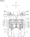
- FIG. 5 is a plan view of a part of the leaning vehicle 1.
- front, rear, left, right, up and down refer to these directions as seen from a virtual rider seated on a seat 5 while the leaning vehicle 1 is standing upright (standing upright as used herein refers to a state where a vehicle body frame 10 to be described below is standing upright) on a horizontal surface with no rider and no load thereon, unless specified otherwise.
- the vehicle up-down direction coincides with the vertical direction.
- the vehicle front-rear direction is orthogonal to the vehicle up-down direction.
- the vehicle left-right direction is orthogonal to the vehicle front-rear direction and the vehicle up-down direction.
- the leaning vehicle 1 includes the vehicle body frame 10, a link mechanism 20, a left front wheel 3L, a right front wheel 3R (see FIG. 4 ), a rear wheel 4, a power unit 2, the seat 5 and a storage box 16.
- the leaning vehicle 1 is a three-wheel vehicle with two front wheels 3L, 3R and one rear wheel 4.
- the vehicle body frame 10 includes a head pipe 11, a down frame 12 extending rearward and downward from the head pipe 11, and a seat frame 13 extending rearward from the down frame 12.
- the seat 5 is supported by the vehicle body frame 10.
- the seat 5 is supported by the seat frame 13.
- the storage box 16 is arranged downward of the seat 5.
- the storage box 16 is supported by the seat frame 13.
- a steering shaft 14 is rotatably supported by the head pipe 11.
- a steering handle 15 is fixed to the steering shaft 14.
- the leaning vehicle 1 is a scooter.
- the leaning vehicle 1 includes a low footrest 7.
- the footrest 7 is supported by the vehicle body frame 10.
- the footrest 7 is supported by the down frame 12 (see FIG. 2 ).
- the footrest 7 is arranged downward of the seat 5.
- the footrest 7 is a platform for supporting the feet of the rider seated on the seat 5.
- the link mechanism 20 is a parallelogram link-type link mechanism.
- the link mechanism 20 is arranged upward relative to the left front wheel 3L and the right front wheel 3R.
- the link mechanism 20 includes an upper arm 21, a lower arm 22, a left arm 23 and a right arm 24.
- the upper arm 21 and the lower arm 22 extend leftward and rightward.
- the upper arm 21 and the lower arm 22 are examples of link members extending leftward and rightward of the vehicle body frame 10.
- the lower arm 22 is arranged downward of the upper arm 21.
- the upper arm 21 and the lower arm 22 are arranged forward of the head pipe 11 (see FIG. 2 ).
- the upper arm 21 is rotatably linked to the head pipe 11 by a first central link shaft 21Cc extending in the vehicle front-rear direction.
- the lower arm 22 is rotatably linked to the head pipe 11 by a second central link shaft 22Cc extending in the vehicle front-rear direction.
- another lower arm 22B is arranged rearward of the head pipe 11.
- the lower arm 22B extends leftward and rightward.
- the lower arm 22B is arranged downward of the upper arm 21.
- the lower arm 22B is rotatably linked to the head pipe 11 by a third central link shaft 23Cc (see FIG. 3 ) extending in the vehicle front-rear direction.
- another upper arm (not shown) may be arranged rearward of the head pipe 11, and this upper arm may be rotatably linked to the head pipe 11 by another central link shaft (not shown) extending in the vehicle front-rear direction.
- the other upper arm and the other lower arm 22B arranged rearward of the head pipe 11 are optional.
- the left arm 23 and the right arm 24 extend upward and downward.
- the left arm 23 is arranged leftward of the head pipe 11 and the right arm 24 is arranged rightward of the head pipe 11.
- the right arm 24 is arranged rightward of the left arm 23.
- the left arm 23 and the right arm 24 are arranged rearward of the upper arm 21 and the lower arm 22.
- the left arm 23 and the right arm 24 are arranged forward of the lower arm 22B.
- the left arm 23 and the right arm 24 are rotatably linked to the upper arm 21, the lower arm 22 and the lower arm 22B.
- the upper end portion of the left arm 23 is rotatably linked to the left end portion of the upper arm 21 by a first left link shaft 21 Lc extending in the vehicle front-rear direction.
- the lower end portion of the left arm 23 is rotatably linked to the left end portion of the lower arm 22 by a second left link shaft 22Lc extending in the vehicle front-rear direction.
- the lower end of the left arm 23 is rotatably linked to the left end portion of the lower arm 22B by a third left link shaft (not shown) extending in the vehicle front-rear direction.
- the upper end portion of the right arm 24 is rotatably linked to the right end portion of the upper arm 21 by the first right link shaft 21 Rc extending in the vehicle front-rear direction.
- the lower end portion of the right arm 24 is rotatably linked to the right end portion of the lower arm 22 by the second right link shaft 22Rc extending in the vehicle front-rear direction.
- the lower end portion of the right arm 24 is rotatably linked to the right end portion of the lower arm 22B by a third right link shaft (not shown) extending in the vehicle front-rear direction.
- the leaning vehicle 1 includes, as front suspensions, a left suspension 25L and a right suspension 25R.
- the left suspension 25L and the right suspension 25R are telescopic suspensions.
- the upper end portion of the left suspension 25L and the upper end portion of the right suspension 25R are connected to the link mechanism 20.
- the lower end portion of the left suspension 25L is connected to the left front wheel 3L, and the lower end portion of the right suspension 25R is connected to the right front wheel 3R.
- the upper end portion of the left suspension 25L is connected to the lower end portion of the left arm 23 via a left bracket 26L.
- the upper end portion of the left suspension 25L is connected to the left arm 23 so as to be rotatable in the left-right direction of the vehicle body frame 10.
- the upper end portion of the right suspension 25R is connected to the lower end portion of the right arm 24 via a right bracket 26R.
- the upper end portion of the right suspension 25R is connected to the right arm 24 so as to be rotatable in the left-right direction of the vehicle body frame 10.
- the left suspension 25L, the left bracket 26L and the left arm 23 together form a left wheel support member 19L that supports the left front wheel 3L.
- the right suspension 25R, the right bracket 26R and the right arm 24 together form a right wheel support member 19R that supports the right front wheel 3R.
- a center plate 27C is fixed to the lower end portion of the steering shaft 14. As shown in FIG. 5 , the center plate 27C extends forward from the steering shaft 14. A left plate 27L is fixed to the left bracket 26L. A right plate 27R is fixed to the right bracket 26R. The left plate 27L, the center plate 27C and the right plate 27R are linked to a tie rod 28 so as to be rotatable left and right.
- the steering shaft 14 is linked to the left arm 23 and the right arm 24 via the center plate 27C, the tie rods 28, the left plate 27L and the right plate 27R.
- the leaning vehicle 1 includes a roll angle control device 30 that controls the roll angle.
- the roll angle as used herein is the tilt angle ⁇ (see FIG. 6 ) of the vehicle body frame 10 from the vertical line.
- the roll angle ⁇ is equal to the angle between the axis of the head pipe 11 and the vertical line as viewed in the vehicle front view.
- the roll angle control device 30 controls the roll angle of the vehicle body frame 10 by adjusting the rotation of the upper arm 21 and the lower arm 22 relative to the vehicle body frame 10.
- the roll angle control device 30 is configured to apply a torque to at least one of the upper arm 21 and the lower arm 22.
- the roll angle control device 30 is connected to at least one of the upper arm 21 and lower arm 22, and to the vehicle body frame 10. In the present embodiment, the roll angle control device 30 is connected to the upper arm 21 and the head pipe 11. Note however that there is no particular limitation thereto, and the roll angle control device 30 may be connected to the lower arm 22 and the head pipe 11.
- the roll angle control device 30 includes a case 31, a lean actuator 33, a gear 35A and a gear 35B arranged inside the case 31, and an actuator control device 36 arranged inside the case 31.
- the case 31 is supported by a support member 32 fixed to the head pipe 11.
- the lean actuator 33 is a power source that applies a torque around the first central link shaft 21Cc to the vehicle body frame 10.
- the lean actuator 33 may apply a torque directly or indirectly to the vehicle body frame 10.
- the lean actuator 33 applies a leftward or rightward torque to the upper arm 21, thereby indirectly applying a rightward or leftward torque to the vehicle body frame 10.
- the lean actuator 33 is an electric motor. Note however that the lean actuator 33 is not limited to an electric motor as long as the lean actuator 33 can generate power.
- the lean actuator 33 is connected to the gear 35A, and the gear 35A is meshed with the gear 35B.
- the gear 35A and the gear 35B together form a decelerator.
- the gear 35B is fixed to an output shaft 34.
- the output shaft 34 is a rotating shaft driven by the lean actuator 33 and is connected to the upper arm 21.
- the torque of the lean actuator 33 is transmitted to the upper arm 21 via the gear 35A, the gear 35B and the output shaft 34.
- a torque around the first central link shaft 21Cc (see FIG. 4 ) is applied to the upper arm 21.
- the upper arm 21 is linked to the vehicle body frame 10 so as to be rotatable around the first central link shaft 21Cc, when a torque around the first central link shaft 21Cc is applied to the upper arm 21, a torque around the first central link shaft 21Cc is generated in the vehicle body frame 10.
- the leaning vehicle 1 includes an IMU (Inertial Measurement Unit) (not shown).
- the actuator control device 36 is communicatively connected to the IMU via a wire harness (not shown).
- the actuator control device 36 is configured to receive a signal from the IMU and control the lean actuator 33.
- a power unit 2 is pivotally supported on the vehicle body frame 10.
- the power unit 2 is connected to the rear wheel 4 so that power can be transmitted therebetween.
- the power unit 2 generates driving force for traveling.
- the power unit 2 provides power to the rear wheel 4.
- the power unit 2 may include an internal combustion engine or may include an electric motor.
- the power unit 2 includes an internal combustion engine (hereinafter referred to as an "engine").
- the leaning vehicle 1 includes left and right rear suspensions 50.
- the left rear suspension 50 is arranged leftward of the rear wheel 4 and the right rear suspension 50 is arranged rightward of the rear wheel 4.
- Each rear suspension 50 includes an upper support portion 51 pivotably supported on the vehicle body frame 10 and a lower support portion 52 pivotably supported on the rear wheel 4.
- the upper support portion 51 is pivotably supported on the seat frame 13 via a bracket 13B.
- the lower support portion 52 is pivotably supported on a bracket 4B mounted on the axle of the rear wheel 4.
- the leaning vehicle 1 includes a control panel 40 (see FIG. 4 ).
- the control panel 40 is arranged upward of the head pipe 11.
- the control panel 40 is arranged rearward of a central portion 15C of the steering handle 15. Note however that there is no particular limitation on the position of the control panel 40 as long as the control panel 40 is in a position where it is visible and operable by the rider seated on the seat 5.
- the control panel 40 according to the present embodiment includes a display device 41 and switches 42A to 42D.
- the control panel 40 also includes a display control device 45 that controls the display device 41.
- the display device 41 can display the speed of the leaning vehicle 1, the engine speed and the amount of fuel, etc..
- the display device 41 is capable of displaying an image showing the status of operation of the lean actuator 33.
- the display device 41 may, for example, include a liquid crystal display or an organic EL display.
- the display device 41 may include LEDs.
- the actuator control device 36 that controls the lean actuator 33, it is possible to control the roll angle when the leaning vehicle 1 is traveling and when the leaning vehicle 1 is stopped.
- the actuator control device 36 can perform the standing assist control as follows.
- the standing assist control is a control of keeping the vehicle body frame 10 standing upright when the leaning vehicle 1 is starting, traveling slowly, or stopped at a stoplight, etc. For example, when the leaning vehicle 1 is traveling slowly, if the rider puts their weight to the left, the vehicle body frame 10 is subjected to a leftward force. As it is, the vehicle body frame 10 will lean leftward.
- the actuator control device 36 detects the tilt of the vehicle body frame 10 based on the signal from the IMU. When the actuator control device 36 detects the tilt of the vehicle body frame 10, the actuator control device 36 controls the lean actuator 33 to eliminate the tilt. Specifically, the actuator control device 36 controls the lean actuator 33 so that the roll angle of the vehicle body frame 10 becomes zero.
- the actuator control device 36 controls the lean actuator 33 so as to apply a rightward torque to the vehicle body frame 10.
- the actuator control device 36 controls the lean actuator 33 so as to apply a leftward torque to the vehicle body frame 10.
- the display control device 45 is configured to display an image showing the status of operation of the lean actuator 33 (hereinafter referred to as an actuator operation image) on the display device 41.
- an actuator operation image the display control device 45 simultaneously displays information on whether the lean actuator 33 is outputting a torque, the direction of the torque output by the lean actuator 33, the magnitude of the torque output by the lean actuator 33, and the degree of tilt of the vehicle body frame 10 from the vertical line on the display device 41.
- FIG. 8 is a diagram of an example of the actuator operation image displayed on the display device 41.
- the image includes a display area 71 in which an image of a vehicle 61 is displayed, a display area 72 in which a leftward arrow 62L is displayed, and a display area 73 in which a rightward arrow 62R is displayed.
- the display area 71 displays the vehicle 61 tilted from the vertical line.
- the image of the vehicle 61 displayed on the display device 41 is a mirror image of the leaning vehicle 1 with left and right reversed.
- the vehicle body frame 10 of the leaning vehicle 1 is tilted leftward
- the vehicle 61 is displayed tilted leftward
- the vehicle body frame 10 is tilted rightward
- the vehicle 61 is displayed tilted rightward.
- the greater the degree of tilt of the vehicle body frame 10 from the vertical line in other words, the greater the roll angle
- the degree of tilt of the vehicle 61 from the vertical line is displayed in the display area 71.
- the lean actuator 33 When the vehicle body frame 10 is tilted rightward, the lean actuator 33 outputs a leftward torque. As shown in FIG. 8 , when the lean actuator 33 is outputting a leftward torque, part or whole of the leftward arrow 62L is displayed in solid black 63 and the entire rightward arrow 62R is displayed in solid white. When the lean actuator 33 is outputting a rightward torque, part or all of the rightward arrow 62R is displayed in solid black 63 and the entire leftward arrow 62L is displayed in solid white. When the lean actuator 33 is not outputting a torque, the entire leftward arrow 62L and the entire rightward arrow 62R are displayed in solid white.
- the greater the torque output by the lean actuator 33 the greater the area of solid black 63. Based on the area of solid black 63, it is possible to know the magnitude of the torque output by the lean actuator 33. Thus, the magnitude of the torque output by the lean actuator 33 is displayed in the display areas 72 and 73.
- FIG. 9 is a diagram showing another example of an actuator operation image.
- This image shows a center block 64, a left block 65 and a right block 66.
- the left block 65 is displayed in solid black when the lean actuator 33 is outputting a leftward torque
- the right block 66 is displayed in solid black when the lean actuator 33 is outputting a rightward torque.
- the left block 65 and the right block 66 are displayed in solid white.
- This image displays information on whether the lean actuator 33 is outputting a torque and the direction of the torque output by the lean actuator 33.
- actuator operation images described above are only an example. Needless to say, the actuator operation image is not limited to the image examples.
- the display image on the display device 41 may be switched automatically.
- the switch 42A (see FIG. 7 ) is the switch for switching ON/OFF the standing assist control.
- the display control device 45 may display the actuator operation image on the display device 41 when the switch 42A is ON and may display another image different from the actuator operation image on the display device 41 when the switch 42A is OFF.
- the display control device 45 may display the speed of the leaning vehicle 1, the engine speed and the amount of fuel, etc., on the display device 41 when the switch 42A is OFF.
- the standing assist control may be turned ON/OFF manually, it may be turned ON/OFF automatically depending on the speed of the leaning vehicle 1. Where the standing assist control is switched ON/OFF automatically, the displayed image on the display device 41 may be switched automatically accordingly.
- the leaning vehicle 1 includes a speed sensor 46 to detect the speed of the leaning vehicle 1.
- the actuator control device 36 is configured to execute the standing assist control when the speed detected by the speed sensor 46 is less than or equal to a threshold value, and to cancel the standing assist control when the speed becomes greater than the threshold value. Note that the speed being less than or equal to the threshold value includes the case where the speed is zero.
- the actuator control device 36 executes the standing assist control when the leaning vehicle 1 is traveling slowly and when it is stopped.
- the display control device 45 causes the actuator operation image to be displayed on the display device 41 when the speed detected by the speed sensor 46 is less than or equal to the threshold value, and causes another image different from the actuator operation image to be displayed on the display device 41 when the speed is greater than the threshold value.
- the standing assist control is started, the displayed image on the display device 41 is automatically switched to the actuator operation image, and when the standing assist control is finished, the displayed image on the display device 41 is automatically switched to another image.
- the leaning vehicle 1 includes an abnormality detection device 47 for detecting an abnormality of the lean actuator 33.
- the display control device 45 is configured to, when the abnormality detection device 47 detects an abnormality of the lean actuator 33, display on the display device 41 that the abnormality has occurred.
- the display control device 45 may display an image indicating the occurrence of an abnormality of the lean actuator 33 on the display device 41 together with the actuator operation image, or may display an image indicating the occurrence of an abnormality of the lean actuator 33 on the display device 41 instead of the actuator operation image.
- the leaning vehicle 1 As described above, the leaning vehicle 1 according to the present embodiment, an image indicating the status of operation of the lean actuator 33 is displayed on the display device 41.
- the rider By looking at the display device 41, the rider can know the status of operation of the lean actuator 33.
- the rider can intuitively understand the status of the standing assist control. Thus, it is easier for the rider to perform an operation in conformity with the operation of the lean actuator 33.
- the rider can drive the leaning vehicle 1 desirably while the lean actuator 33 is operating.
- information on whether the lean actuator 33 is outputting a torque is displayed on the display device 41.
- the rider can easily know whether the lean actuator 33 is outputting a torque. For example, before the leaning vehicle 1 decelerates to a stop, the rider can know that standing assist is being provided. The rider can stop the leaning vehicle 1 with confidence.
- the direction of the torque output by the lean actuator 33 is displayed on the display device 41.
- the rider can easily know the direction of the torque output by the lean actuator 33.
- the rider can intuitively understand the operation of the lean actuator 33.
- the magnitude of the torque output by the lean actuator 33 is displayed on the display device 41.
- the rider can easily know the magnitude of the torque output by the lean actuator 33. For example, if the torque output by the lean actuator 33 is large, the rider can refrain from abrupt maneuvers (e.g., suddenly turning the acceleration grip for rapid acceleration) so as to stabilize the attitude of the leaning vehicle 1.
- the rider can drive the leaning vehicle 1 desirably.
- the degree of tilt of the vehicle body frame 10 from the vertical line is displayed on the display device 41.
- the rider can easily know the degree of tilt of the vehicle body frame 10. For example, if the degree of tilt of the vehicle body frame 10 is large, the rider can refrain from abrupt maneuvers so as to stabilize the attitude of the leaning vehicle 1.
- the rider can drive the leaning vehicle 1 desirably.
- information on whether the lean actuator 33 is outputting a torque, the direction of the torque output by the lean actuator 33, the magnitude of the torque output by the lean actuator 33, and the degree of tilt of the vehicle body frame 10 from the vertical line are displayed at the same time on the display device 41.
- the rider can more specifically understand the status of the standing assist control.
- the abnormality detection device 47 detects the abnormality and indicates on the display device 41 that an abnormality has occurred in the lean actuator 33.
- the rider can immediately know an abnormality of the lean actuator 33. Therefore, the rider can take appropriate action, such as stopping driving the leaning vehicle 1.
- the display control device 45 may display the actuator operation image on the display device 41 when the switch 42A for switching ON/OFF the standing assist control is ON, and display another image different from the actuator operation image on the display device 41 when the switch 42A is OFF.
- the rider can know the status of operation of the lean actuator 33 as needed.
- a single display device 41 it is possible to selectively display both the actuator operation image and another image. The number of display devices can be reduced compared to where a dedicated display device for displaying the actuator operation image is provided.
- the actuator control device 36 may be configured to perform the standing assist control when the speed of the leaning vehicle 1 detected by the speed sensor 46 is less than or equal to a threshold value and to not perform the standing assist control when the speed of the leaning vehicle 1 is greater than the threshold value.
- the display control device 45 may display an actuator operation image on the display device 41 when the speed of the leaning vehicle 1 detected by the speed sensor 46 is less than or equal to the threshold value and display another image on the display device 41 when the speed of the leaning vehicle 1 is greater than the threshold value.
- the rider can know the status of operation of the lean actuator 33 as needed. Since a single display device 41 can selectively display both the actuator operation image and another image, it is possible to reduce the number of display devices.
- actuator operation images shown in FIG. 8 and FIG. 9 are merely examples.
- Actuator operation images that the display control device 45 displays on the display device 41 may be other images.
- the display control device 45 may display, as the actuator operation image on the display device 41, only one of, or simultaneously two or three of, information on whether the lean actuator 33 is outputting a torque, the direction of the torque output by the lean actuator 33, the magnitude of the torque output by the lean actuator 33, and the degree of tilt of the vehicle body frame 10 from the vertical line.
- the display control device 45 may switch between a plurality of actuator operation images to be displayed on the display device 41.
- a solid color other than solid black may be used.
- the size of the arrows 62L and 62R may be varied depending on the magnitude of the torque output by the lean actuator 33.
- a blinking display may be used instead of the solid black display.
- While the status of the operation of the lean actuator 33 is displayed by graphics in the actuator images of FIG. 8 and FIG. 9 , letters, numbers or symbols may be displayed in addition to, or instead of, the graphics.
- the presence or absence of the torque of the lean actuator 33 and the direction of the torque output by the lean actuator 33 may be displayed in letters.
- the magnitude of the torque output by the lean actuator 33 or the degree of tilt of the vehicle body frame 10 may be displayed in numbers.
- the leaning vehicle 1 in the embodiment described above is a scooter.
- the form of vehicle of the leaning vehicle is not limited to a scooter.
Landscapes
- Engineering & Computer Science (AREA)
- Mechanical Engineering (AREA)
- Chemical & Material Sciences (AREA)
- Combustion & Propulsion (AREA)
- Transportation (AREA)
- Automatic Cycles, And Cycles In General (AREA)
- Fittings On The Vehicle Exterior For Carrying Loads, And Devices For Holding Or Mounting Articles (AREA)
Abstract
Description
- The present invention relates to a leaning vehicle having a left wheel and a right wheel, wherein the leaning vehicle tilts when turning left and right.
- As disclosed in
JP 2019-196 108 A - According to a leaning vehicle including a lean actuator, the lean actuator can be controlled to keep the vehicle body standing by itself. Hereinafter, keeping the vehicle body standing by itself by using the lean actuator will be referred to as standing assist. By providing standing assist when the vehicle is stopped, the vehicle body can be kept from leaning even if the rider does not put their feet on the ground. In addition, by providing standing assist when starting or traveling at low speeds, the vehicle body does not lean, making driving easier. Thus, the lean actuator provides standing assist to reduce the burden on the rider when starting, when traveling at low speeds, or when the vehicle is stopped.
- Now, standing assist is a control performed by the lean actuator operating accordingly, but in a conventional leaning vehicle, the rider cannot know how the lean actuator is operating. There were cases where the operation of the lean actuator did not match with the driving operation of the rider. This may have made it difficult for the rider to drive the leaning vehicle desirably.
- The present invention has been made in view of the above, and an object thereof is to provide a leaning vehicle that is easy for the rider to drive desirably while the lean actuator is operating, and, thus, to increase safety during driving.
- To solve the aforementioned problem, a leaning vehicle having the features of
claim 1 is provided. A leaning vehicle disclosed herein includes: a vehicle body frame including a head pipe; a left wheel arranged leftward relative to the head pipe; a right wheel arranged rightward relative to the head pipe; a left wheel support member supporting the left wheel; a right wheel support member arranged rightward of the left wheel support member and supporting the right wheel; a link member extending leftward and rightward of the vehicle body frame; a central link shaft extending in a vehicle front-rear direction that rotatably links the vehicle body frame to the link member; a left link shaft extending in the vehicle front-rear direction that rotatably links the left wheel support member to the link member; a right link shaft extending in the vehicle front-rear direction that rotatably links the right wheel support member to the link member; a lean actuator that applies a leftward or rightward torque around the central link shaft to the vehicle body frame; a display device; and a display control device that displays an image indicating a status of operation of the lean actuator on the display device. - With the leaning vehicle described above, as the image indicating the status of operation of the lean actuator is displayed on the display device, the rider can know the status of operation of the lean actuator by looking at the image. The rider can easily perform an operation in conformity with the operation of the lean actuator. Therefore, the rider can drive the leaning vehicle desirably while the lean actuator is operating.
- The display control device may be configured to display information on whether the lean actuator is outputting a torque on the display device.
- Thus, by looking at the display device, the rider can easily know whether the lean actuator is outputting a torque.
- The display control device may be configured to display a direction of the torque output by the lean actuator on the display device.
- Thus, by looking at the display device, the rider can easily know whether the lean actuator is outputting a leftward torque or a rightward torque.
- The display control device may be configured to display a magnitude of the torque output by the lean actuator on the display device.
- Thus, by looking at the display device, the rider can easily know the magnitude of the torque output by the lean actuator.
- The display control device may be configured to display a degree of tilt of the vehicle body frame from a vertical line on the display device.
- Thus, by looking at the display device, the rider can easily know the degree of tilt of the vehicle body frame.
- The display control device may be configured to simultaneously display, on the display device, two or more of information on whether the lean actuator is outputting a torque, a direction of the torque output by the lean actuator, a magnitude of the torque output by the lean actuator, and a degree of tilt of the vehicle body frame from a vertical line.
- Thus, by looking at the display device, the rider can simultaneously know two or more of information on whether the lean actuator is outputting a torque, the direction of the torque, the magnitude of the torque, and the degree of tilt of the vehicle body frame.
- The leaning vehicle may include an abnormality detection device that detects an abnormality of the lean actuator. The display control device may be configured to, when the abnormality detection device detects an abnormality of the lean actuator, indicate on the display device that the abnormality has occurred.
- Thus, when an abnormality occurs in the lean actuator, the rider can immediately know the abnormality by looking at the display device.
- The leaning vehicle may include: an actuator control device that executes a standing assist control of controlling the lean actuator to keep the vehicle body frame standing by itself; and a switch that switches ON/OFF the standing assist control. The display control device may be configured to display the image indicating the status of operation of the lean actuator on the display device when the switch is ON, and display another image different from said image on the display device when the switch is OFF.
- Thus, as the rider operates the switch to turn ON the standing assist control, the image on the display device is switched from another image to an image that indicates the status of operation of the lean actuator. Thus, the rider can know the status of operation of the lean actuator as needed. There is no need for a dedicated display device for displaying an image indicating the status of operation of the lean actuator. It is possible to reduce the number of display devices.
- The leaning vehicle may include: a speed sensor that detects a speed of the leaning vehicle; and an actuator control device that executes a standing assist control of controlling the lean actuator to keep the vehicle body frame standing by itself when the speed detected by the speed sensor is less than or equal to a threshold value. The display control device may be configured to display the image indicating the status of operation of the lean actuator on the display device when the speed detected by the speed sensor is less than or equal to the threshold value, and display another image different from said image on the display device when the speed is greater than the threshold value.
- Thus, when the speed of the leaning vehicle is less than or equal to the threshold value, the standing assist control is executed automatically, and the image on the display device is automatically switched to an image indicating the status of operation of the lean actuator. Thus, the rider can know the status of operation of the lean actuator as needed. There is no need for a dedicated display device for displaying an image indicating the status of operation of the lean actuator. It is possible to reduce the number of display devices.
- The leaning vehicle may include: a steering shaft supported by the head pipe; and a steering handle fixed to the steering shaft. The left wheel and the right wheel are a left front wheel and a right front wheel, respectively, arranged forward relative to the steering handle.
- The leaning vehicle may include: a seat supported by the vehicle body frame; and a footrest supported by the vehicle body frame, arranged downward of the seat and supporting feet of a rider seated on the seat.
Another aspect of the present invention is a system for a leaning vehicle, wherein the system comprises the lean actuator and the display control device.
Hence, the system can be retrofitted to the leaning vehicle having the link member and the central link shaft. In addition, the system may comprise the display device. - According to the present invention, it is possible to provide a leaning vehicle that is easy for the rider to drive desirably while the lean actuator is operating.
-
-
FIG. 1 is a left side view of a leaning vehicle according to one embodiment. -
FIG. 2 is a left side view of a part of the leaning vehicle. -
FIG. 3 is a left side view of a part of the leaning vehicle. -
FIG. 4 is a front view of a part of the leaning vehicle. -
FIG. 5 is a plan view of a part of the leaning vehicle. -
FIG. 6 is a front view of a part of the leaning vehicle with the vehicle body frame tilted leftward. -
FIG. 7 is a view of the control panel and the display control device. -
FIG. 8 is a diagram of an example of an actuator operation image displayed on the display device. -
FIG. 9 is a diagram showing another example of an actuator operation image displayed on the display device. -
FIG. 10 is a block diagram according to an example of the control system for the leaning vehicle. -
FIG. 11 is a block diagram according to another example of the control system for the leaning vehicle. - One embodiment of a leaning vehicle will now be described with reference to the drawings.
FIG. 1 is a left side view of a leaningvehicle 1 according to the present embodiment.FIG. 2 is a left side view of a part of the leaningvehicle 1.FIG. 3 is a left side view of a part of the leaningvehicle 1.FIG. 4 is a front view of a part of the leaningvehicle 1.FIG. 5 is a plan view of a part of the leaningvehicle 1. - The terms front, rear, left, right, up and down, as used in the description below, refer to these directions as seen from a virtual rider seated on a
seat 5 while the leaningvehicle 1 is standing upright (standing upright as used herein refers to a state where avehicle body frame 10 to be described below is standing upright) on a horizontal surface with no rider and no load thereon, unless specified otherwise. The designations F, B, L, R, U and D, as used in the figures, refer to front, rear, left, right, up and down, respectively. The vehicle up-down direction coincides with the vertical direction. The vehicle front-rear direction is orthogonal to the vehicle up-down direction. The vehicle left-right direction is orthogonal to the vehicle front-rear direction and the vehicle up-down direction. - As shown in
FIG. 1 andFIG. 2 , the leaningvehicle 1 includes thevehicle body frame 10, alink mechanism 20, aleft front wheel 3L, aright front wheel 3R (seeFIG. 4 ), arear wheel 4, apower unit 2, theseat 5 and astorage box 16. The leaningvehicle 1 is a three-wheel vehicle with twofront wheels rear wheel 4. - As shown in
FIG. 2 , thevehicle body frame 10 includes ahead pipe 11, adown frame 12 extending rearward and downward from thehead pipe 11, and aseat frame 13 extending rearward from thedown frame 12. Theseat 5 is supported by thevehicle body frame 10. Herein, theseat 5 is supported by theseat frame 13. Thestorage box 16 is arranged downward of theseat 5. Thestorage box 16 is supported by theseat frame 13. As shown inFIG. 4 , a steeringshaft 14 is rotatably supported by thehead pipe 11. A steering handle 15 is fixed to the steeringshaft 14. - As shown in
FIG. 1 , the leaningvehicle 1 according to the present embodiment is a scooter. The leaningvehicle 1 includes alow footrest 7. Thefootrest 7 is supported by thevehicle body frame 10. Herein, thefootrest 7 is supported by the down frame 12 (seeFIG. 2 ). Thefootrest 7 is arranged downward of theseat 5. Thefootrest 7 is a platform for supporting the feet of the rider seated on theseat 5. - As shown in
FIG. 4 , thelink mechanism 20 is a parallelogram link-type link mechanism. Thelink mechanism 20 is arranged upward relative to theleft front wheel 3L and theright front wheel 3R. Thelink mechanism 20 includes anupper arm 21, alower arm 22, aleft arm 23 and aright arm 24. - The
upper arm 21 and thelower arm 22 extend leftward and rightward. Theupper arm 21 and thelower arm 22 are examples of link members extending leftward and rightward of thevehicle body frame 10. Thelower arm 22 is arranged downward of theupper arm 21. Theupper arm 21 and thelower arm 22 are arranged forward of the head pipe 11 (seeFIG. 2 ). Theupper arm 21 is rotatably linked to thehead pipe 11 by a first central link shaft 21Cc extending in the vehicle front-rear direction. Thelower arm 22 is rotatably linked to thehead pipe 11 by a second central link shaft 22Cc extending in the vehicle front-rear direction. - In the present embodiment, as shown in
FIG. 2 , anotherlower arm 22B is arranged rearward of thehead pipe 11. Thelower arm 22B extends leftward and rightward. Thelower arm 22B is arranged downward of theupper arm 21. Thelower arm 22B is rotatably linked to thehead pipe 11 by a third central link shaft 23Cc (seeFIG. 3 ) extending in the vehicle front-rear direction. Note that another upper arm (not shown) may be arranged rearward of thehead pipe 11, and this upper arm may be rotatably linked to thehead pipe 11 by another central link shaft (not shown) extending in the vehicle front-rear direction. Note however that the other upper arm and the otherlower arm 22B arranged rearward of thehead pipe 11 are optional. - As shown in
FIG. 4 , theleft arm 23 and theright arm 24 extend upward and downward. Theleft arm 23 is arranged leftward of thehead pipe 11 and theright arm 24 is arranged rightward of thehead pipe 11. Theright arm 24 is arranged rightward of theleft arm 23. Theleft arm 23 and theright arm 24 are arranged rearward of theupper arm 21 and thelower arm 22. Theleft arm 23 and theright arm 24 are arranged forward of thelower arm 22B. Theleft arm 23 and theright arm 24 are rotatably linked to theupper arm 21, thelower arm 22 and thelower arm 22B. - Specifically, the upper end portion of the
left arm 23 is rotatably linked to the left end portion of theupper arm 21 by a firstleft link shaft 21 Lc extending in the vehicle front-rear direction. The lower end portion of theleft arm 23 is rotatably linked to the left end portion of thelower arm 22 by a second left link shaft 22Lc extending in the vehicle front-rear direction. The lower end of theleft arm 23 is rotatably linked to the left end portion of thelower arm 22B by a third left link shaft (not shown) extending in the vehicle front-rear direction. The upper end portion of theright arm 24 is rotatably linked to the right end portion of theupper arm 21 by the firstright link shaft 21 Rc extending in the vehicle front-rear direction. The lower end portion of theright arm 24 is rotatably linked to the right end portion of thelower arm 22 by the second right link shaft 22Rc extending in the vehicle front-rear direction. The lower end portion of theright arm 24 is rotatably linked to the right end portion of thelower arm 22B by a third right link shaft (not shown) extending in the vehicle front-rear direction. - The leaning
vehicle 1 includes, as front suspensions, aleft suspension 25L and aright suspension 25R. In the present embodiment, theleft suspension 25L and theright suspension 25R are telescopic suspensions. The upper end portion of theleft suspension 25L and the upper end portion of theright suspension 25R are connected to thelink mechanism 20. The lower end portion of theleft suspension 25L is connected to theleft front wheel 3L, and the lower end portion of theright suspension 25R is connected to theright front wheel 3R. Specifically, the upper end portion of theleft suspension 25L is connected to the lower end portion of theleft arm 23 via aleft bracket 26L. The upper end portion of theleft suspension 25L is connected to theleft arm 23 so as to be rotatable in the left-right direction of thevehicle body frame 10. The upper end portion of theright suspension 25R is connected to the lower end portion of theright arm 24 via aright bracket 26R. The upper end portion of theright suspension 25R is connected to theright arm 24 so as to be rotatable in the left-right direction of thevehicle body frame 10. - The
left suspension 25L, theleft bracket 26L and theleft arm 23 together form a leftwheel support member 19L that supports theleft front wheel 3L. Theright suspension 25R, theright bracket 26R and theright arm 24 together form a rightwheel support member 19R that supports theright front wheel 3R. - A
center plate 27C is fixed to the lower end portion of the steeringshaft 14. As shown inFIG. 5 , thecenter plate 27C extends forward from the steeringshaft 14. Aleft plate 27L is fixed to theleft bracket 26L. Aright plate 27R is fixed to theright bracket 26R. Theleft plate 27L, thecenter plate 27C and theright plate 27R are linked to atie rod 28 so as to be rotatable left and right. The steeringshaft 14 is linked to theleft arm 23 and theright arm 24 via thecenter plate 27C, thetie rods 28, theleft plate 27L and theright plate 27R. - As shown in
FIG. 3 , the leaningvehicle 1 includes a rollangle control device 30 that controls the roll angle. Note that in the figures other thanFIG. 3 , the rollangle control device 30 is not shown. The roll angle as used herein is the tilt angle θ (seeFIG. 6 ) of thevehicle body frame 10 from the vertical line. Note that in the present embodiment, the roll angle θ is equal to the angle between the axis of thehead pipe 11 and the vertical line as viewed in the vehicle front view. The rollangle control device 30 controls the roll angle of thevehicle body frame 10 by adjusting the rotation of theupper arm 21 and thelower arm 22 relative to thevehicle body frame 10. The rollangle control device 30 is configured to apply a torque to at least one of theupper arm 21 and thelower arm 22. The rollangle control device 30 is connected to at least one of theupper arm 21 andlower arm 22, and to thevehicle body frame 10. In the present embodiment, the rollangle control device 30 is connected to theupper arm 21 and thehead pipe 11. Note however that there is no particular limitation thereto, and the rollangle control device 30 may be connected to thelower arm 22 and thehead pipe 11. - The roll
angle control device 30 includes acase 31, alean actuator 33, agear 35A and agear 35B arranged inside thecase 31, and anactuator control device 36 arranged inside thecase 31. Thecase 31 is supported by asupport member 32 fixed to thehead pipe 11. - The
lean actuator 33 is a power source that applies a torque around the first central link shaft 21Cc to thevehicle body frame 10. Thelean actuator 33 may apply a torque directly or indirectly to thevehicle body frame 10. In the present embodiment, thelean actuator 33 applies a leftward or rightward torque to theupper arm 21, thereby indirectly applying a rightward or leftward torque to thevehicle body frame 10. In the present embodiment, thelean actuator 33 is an electric motor. Note however that thelean actuator 33 is not limited to an electric motor as long as thelean actuator 33 can generate power. - The
lean actuator 33 is connected to thegear 35A, and thegear 35A is meshed with thegear 35B. Thegear 35A and thegear 35B together form a decelerator. Thegear 35B is fixed to anoutput shaft 34. Theoutput shaft 34 is a rotating shaft driven by thelean actuator 33 and is connected to theupper arm 21. The torque of thelean actuator 33 is transmitted to theupper arm 21 via thegear 35A, thegear 35B and theoutput shaft 34. When thelean actuator 33 is driven, a torque around the first central link shaft 21Cc (seeFIG. 4 ) is applied to theupper arm 21. Since theupper arm 21 is linked to thevehicle body frame 10 so as to be rotatable around the first central link shaft 21Cc, when a torque around the first central link shaft 21Cc is applied to theupper arm 21, a torque around the first central link shaft 21Cc is generated in thevehicle body frame 10. - The leaning
vehicle 1 includes an IMU (Inertial Measurement Unit) (not shown). Theactuator control device 36 is communicatively connected to the IMU via a wire harness (not shown). Theactuator control device 36 is configured to receive a signal from the IMU and control thelean actuator 33. - As shown in
FIG. 2 , apower unit 2 is pivotally supported on thevehicle body frame 10. Thepower unit 2 is connected to therear wheel 4 so that power can be transmitted therebetween. Thepower unit 2 generates driving force for traveling. Thepower unit 2 provides power to therear wheel 4. Thepower unit 2 may include an internal combustion engine or may include an electric motor. In the present embodiment, thepower unit 2 includes an internal combustion engine (hereinafter referred to as an "engine"). - The leaning
vehicle 1 includes left and rightrear suspensions 50. The leftrear suspension 50 is arranged leftward of therear wheel 4 and the rightrear suspension 50 is arranged rightward of therear wheel 4. Eachrear suspension 50 includes anupper support portion 51 pivotably supported on thevehicle body frame 10 and alower support portion 52 pivotably supported on therear wheel 4. Herein, theupper support portion 51 is pivotably supported on theseat frame 13 via abracket 13B. Thelower support portion 52 is pivotably supported on abracket 4B mounted on the axle of therear wheel 4. - The leaning
vehicle 1 includes a control panel 40 (seeFIG. 4 ). Thecontrol panel 40 is arranged upward of thehead pipe 11. Thecontrol panel 40 is arranged rearward of acentral portion 15C of thesteering handle 15. Note however that there is no particular limitation on the position of thecontrol panel 40 as long as thecontrol panel 40 is in a position where it is visible and operable by the rider seated on theseat 5. As shown inFIG. 7 , thecontrol panel 40 according to the present embodiment includes adisplay device 41 andswitches 42A to 42D. Thecontrol panel 40 also includes adisplay control device 45 that controls thedisplay device 41. - The
display device 41 can display the speed of the leaningvehicle 1, the engine speed and the amount of fuel, etc.. Thedisplay device 41 is capable of displaying an image showing the status of operation of thelean actuator 33. There is no particular limitation on the form of thedisplay device 41. Thedisplay device 41 may, for example, include a liquid crystal display or an organic EL display. Thedisplay device 41 may include LEDs. - With the leaning
vehicle 1 according to the present embodiment, with the provision of theactuator control device 36 that controls thelean actuator 33, it is possible to control the roll angle when the leaningvehicle 1 is traveling and when the leaningvehicle 1 is stopped. There is no particular limitation on the control performed by theactuator control device 36. Theactuator control device 36 can perform the standing assist control as follows. - The standing assist control is a control of keeping the
vehicle body frame 10 standing upright when the leaningvehicle 1 is starting, traveling slowly, or stopped at a stoplight, etc. For example, when the leaningvehicle 1 is traveling slowly, if the rider puts their weight to the left, thevehicle body frame 10 is subjected to a leftward force. As it is, thevehicle body frame 10 will lean leftward. Theactuator control device 36 detects the tilt of thevehicle body frame 10 based on the signal from the IMU. When theactuator control device 36 detects the tilt of thevehicle body frame 10, theactuator control device 36 controls thelean actuator 33 to eliminate the tilt. Specifically, theactuator control device 36 controls thelean actuator 33 so that the roll angle of thevehicle body frame 10 becomes zero. When thevehicle body frame 10 leans leftward, theactuator control device 36 controls thelean actuator 33 so as to apply a rightward torque to thevehicle body frame 10. When thevehicle body frame 10 leans rightward, theactuator control device 36 controls thelean actuator 33 so as to apply a leftward torque to thevehicle body frame 10. - The
display control device 45 is configured to display an image showing the status of operation of the lean actuator 33 (hereinafter referred to as an actuator operation image) on thedisplay device 41. In the present embodiment, as the actuator operation image, thedisplay control device 45 simultaneously displays information on whether thelean actuator 33 is outputting a torque, the direction of the torque output by thelean actuator 33, the magnitude of the torque output by thelean actuator 33, and the degree of tilt of thevehicle body frame 10 from the vertical line on thedisplay device 41. -
FIG. 8 is a diagram of an example of the actuator operation image displayed on thedisplay device 41. The image includes adisplay area 71 in which an image of avehicle 61 is displayed, adisplay area 72 in which aleftward arrow 62L is displayed, and adisplay area 73 in which arightward arrow 62R is displayed. - When the
vehicle body frame 10 is tilted from the vertical line, thedisplay area 71 displays thevehicle 61 tilted from the vertical line. Note that since thedisplay device 41 is viewed by the rider seated on theseat 5, the image of thevehicle 61 displayed on thedisplay device 41 is a mirror image of the leaningvehicle 1 with left and right reversed. When thevehicle body frame 10 of the leaningvehicle 1 is tilted leftward, thevehicle 61 is displayed tilted leftward, and when thevehicle body frame 10 is tilted rightward, thevehicle 61 is displayed tilted rightward. Here, the greater the degree of tilt of thevehicle body frame 10 from the vertical line (in other words, the greater the roll angle), the greater the degree of tilt of thevehicle 61 from the vertical line. Thus, the direction and degree of tilt of thevehicle body frame 10 from the vertical line is displayed in thedisplay area 71. - When the
vehicle body frame 10 is tilted rightward, thelean actuator 33 outputs a leftward torque. As shown inFIG. 8 , when thelean actuator 33 is outputting a leftward torque, part or whole of theleftward arrow 62L is displayed in solid black 63 and the entirerightward arrow 62R is displayed in solid white. When thelean actuator 33 is outputting a rightward torque, part or all of therightward arrow 62R is displayed in solid black 63 and the entireleftward arrow 62L is displayed in solid white. When thelean actuator 33 is not outputting a torque, the entireleftward arrow 62L and the entirerightward arrow 62R are displayed in solid white. Therefore, based on the presence or absence of solid black 63 in theleftward arrow 62L and therightward arrow 62R, it is possible to know information on whether thelean actuator 33 is outputting a torque and the direction of the torque output by thelean actuator 33. Thus, the information of whether thelean actuator 33 is outputting a torque and the direction of the torque output by thelean actuator 33 are displayed in thedisplay areas - Here, in the
leftward arrow 62L and therightward arrow 62R, the greater the torque output by thelean actuator 33, the greater the area of solid black 63. Based on the area of solid black 63, it is possible to know the magnitude of the torque output by thelean actuator 33. Thus, the magnitude of the torque output by thelean actuator 33 is displayed in thedisplay areas -
FIG. 9 is a diagram showing another example of an actuator operation image. This image shows acenter block 64, aleft block 65 and aright block 66. In this image, theleft block 65 is displayed in solid black when thelean actuator 33 is outputting a leftward torque, and theright block 66 is displayed in solid black when thelean actuator 33 is outputting a rightward torque. When thelean actuator 33 is not outputting a torque, theleft block 65 and theright block 66 are displayed in solid white. This image displays information on whether thelean actuator 33 is outputting a torque and the direction of the torque output by thelean actuator 33. - Note that the actuator operation images described above are only an example. Needless to say, the actuator operation image is not limited to the image examples.
- Now, when the
actuator control device 36 is not performing the standing assist control, the rider does not need to know the status of operation of thelean actuator 33. Therefore, when the rider turns ON/OFF the standing assist control, the display image on thedisplay device 41 may be switched automatically. For example, assume that theswitch 42A (seeFIG. 7 ) is the switch for switching ON/OFF the standing assist control. When the rider turns ON theswitch 42A, the standing assist control by theactuator control device 36 is initiated, and when the rider turns OFF theswitch 42A, the standing assist control by theactuator control device 36 is terminated. Thedisplay control device 45 may display the actuator operation image on thedisplay device 41 when theswitch 42A is ON and may display another image different from the actuator operation image on thedisplay device 41 when theswitch 42A is OFF. For example, thedisplay control device 45 may display the speed of the leaningvehicle 1, the engine speed and the amount of fuel, etc., on thedisplay device 41 when theswitch 42A is OFF. - While the standing assist control may be turned ON/OFF manually, it may be turned ON/OFF automatically depending on the speed of the leaning
vehicle 1. Where the standing assist control is switched ON/OFF automatically, the displayed image on thedisplay device 41 may be switched automatically accordingly. As shown inFIG. 10 , the leaningvehicle 1 includes aspeed sensor 46 to detect the speed of the leaningvehicle 1. In one other embodiment, theactuator control device 36 is configured to execute the standing assist control when the speed detected by thespeed sensor 46 is less than or equal to a threshold value, and to cancel the standing assist control when the speed becomes greater than the threshold value. Note that the speed being less than or equal to the threshold value includes the case where the speed is zero. Theactuator control device 36 executes the standing assist control when the leaningvehicle 1 is traveling slowly and when it is stopped. Thedisplay control device 45 causes the actuator operation image to be displayed on thedisplay device 41 when the speed detected by thespeed sensor 46 is less than or equal to the threshold value, and causes another image different from the actuator operation image to be displayed on thedisplay device 41 when the speed is greater than the threshold value. As a result, when the standing assist control is started, the displayed image on thedisplay device 41 is automatically switched to the actuator operation image, and when the standing assist control is finished, the displayed image on thedisplay device 41 is automatically switched to another image. - As shown in
FIG. 11 , the leaningvehicle 1 according to the present embodiment includes anabnormality detection device 47 for detecting an abnormality of thelean actuator 33. Thedisplay control device 45 is configured to, when theabnormality detection device 47 detects an abnormality of thelean actuator 33, display on thedisplay device 41 that the abnormality has occurred. Thedisplay control device 45 may display an image indicating the occurrence of an abnormality of thelean actuator 33 on thedisplay device 41 together with the actuator operation image, or may display an image indicating the occurrence of an abnormality of thelean actuator 33 on thedisplay device 41 instead of the actuator operation image. - As described above, the leaning
vehicle 1 according to the present embodiment, an image indicating the status of operation of thelean actuator 33 is displayed on thedisplay device 41. By looking at thedisplay device 41, the rider can know the status of operation of thelean actuator 33. The rider can intuitively understand the status of the standing assist control. Thus, it is easier for the rider to perform an operation in conformity with the operation of thelean actuator 33. The rider can drive the leaningvehicle 1 desirably while thelean actuator 33 is operating. - According to the present embodiment, information on whether the
lean actuator 33 is outputting a torque is displayed on thedisplay device 41. By looking at thedisplay device 41, the rider can easily know whether thelean actuator 33 is outputting a torque. For example, before the leaningvehicle 1 decelerates to a stop, the rider can know that standing assist is being provided. The rider can stop the leaningvehicle 1 with confidence. - According to the present embodiment, the direction of the torque output by the
lean actuator 33 is displayed on thedisplay device 41. By looking at thedisplay device 41, the rider can easily know the direction of the torque output by thelean actuator 33. The rider can intuitively understand the operation of thelean actuator 33. - According to the present embodiment, the magnitude of the torque output by the
lean actuator 33 is displayed on thedisplay device 41. By looking at thedisplay device 41, the rider can easily know the magnitude of the torque output by thelean actuator 33. For example, if the torque output by thelean actuator 33 is large, the rider can refrain from abrupt maneuvers (e.g., suddenly turning the acceleration grip for rapid acceleration) so as to stabilize the attitude of the leaningvehicle 1. The rider can drive the leaningvehicle 1 desirably. - According to the present embodiment, the degree of tilt of the
vehicle body frame 10 from the vertical line is displayed on thedisplay device 41. By looking at thedisplay device 41, the rider can easily know the degree of tilt of thevehicle body frame 10. For example, if the degree of tilt of thevehicle body frame 10 is large, the rider can refrain from abrupt maneuvers so as to stabilize the attitude of the leaningvehicle 1. The rider can drive the leaningvehicle 1 desirably. - According to the present embodiment, information on whether the
lean actuator 33 is outputting a torque, the direction of the torque output by thelean actuator 33, the magnitude of the torque output by thelean actuator 33, and the degree of tilt of thevehicle body frame 10 from the vertical line are displayed at the same time on thedisplay device 41. Thus, the rider can more specifically understand the status of the standing assist control. - According to the present embodiment, when an abnormality occurs in the
lean actuator 33, theabnormality detection device 47 detects the abnormality and indicates on thedisplay device 41 that an abnormality has occurred in thelean actuator 33. The rider can immediately know an abnormality of thelean actuator 33. Therefore, the rider can take appropriate action, such as stopping driving the leaningvehicle 1. - As mentioned above, the
display control device 45 may display the actuator operation image on thedisplay device 41 when theswitch 42A for switching ON/OFF the standing assist control is ON, and display another image different from the actuator operation image on thedisplay device 41 when theswitch 42A is OFF. Thus, the rider can know the status of operation of thelean actuator 33 as needed. With asingle display device 41, it is possible to selectively display both the actuator operation image and another image. The number of display devices can be reduced compared to where a dedicated display device for displaying the actuator operation image is provided. - As described above, the
actuator control device 36 may be configured to perform the standing assist control when the speed of the leaningvehicle 1 detected by thespeed sensor 46 is less than or equal to a threshold value and to not perform the standing assist control when the speed of the leaningvehicle 1 is greater than the threshold value. Thedisplay control device 45 may display an actuator operation image on thedisplay device 41 when the speed of the leaningvehicle 1 detected by thespeed sensor 46 is less than or equal to the threshold value and display another image on thedisplay device 41 when the speed of the leaningvehicle 1 is greater than the threshold value. Thus, the rider can know the status of operation of thelean actuator 33 as needed. Since asingle display device 41 can selectively display both the actuator operation image and another image, it is possible to reduce the number of display devices. - While an embodiment of the leaning vehicle has been described above, the embodiment is merely an example. Various other embodiments are possible.
- As described above, actuator operation images shown in
FIG. 8 andFIG. 9 are merely examples. Actuator operation images that thedisplay control device 45 displays on thedisplay device 41 may be other images. Thedisplay control device 45 may display, as the actuator operation image on thedisplay device 41, only one of, or simultaneously two or three of, information on whether thelean actuator 33 is outputting a torque, the direction of the torque output by thelean actuator 33, the magnitude of the torque output by thelean actuator 33, and the degree of tilt of thevehicle body frame 10 from the vertical line. Thedisplay control device 45 may switch between a plurality of actuator operation images to be displayed on thedisplay device 41. - In the actuator operation images shown in
FIG. 8 andFIG. 9 , instead of solid black, a solid color other than solid black may be used. Instead of using the solid black and solid white display for thearrows FIG. 8 , the size of thearrows lean actuator 33. In the actuator operation image ofFIG. 9 , a blinking display may be used instead of the solid black display. - While the status of the operation of the
lean actuator 33 is displayed by graphics in the actuator images ofFIG. 8 andFIG. 9 , letters, numbers or symbols may be displayed in addition to, or instead of, the graphics. For example, the presence or absence of the torque of thelean actuator 33 and the direction of the torque output by thelean actuator 33 may be displayed in letters. The magnitude of the torque output by thelean actuator 33 or the degree of tilt of thevehicle body frame 10 may be displayed in numbers. - The leaning
vehicle 1 in the embodiment described above is a scooter. However, the form of vehicle of the leaning vehicle is not limited to a scooter. - 1: Leaning vehicle, 3L: Left front wheel (left wheel), 3R: Right front wheel (right wheel), 5: Seat, 7: Footrest, 10: Vehicle body frame, 11: Head pipe, 14: Steering shaft, 15: Steering handle, 19L: Left wheel support member, 19R: Right wheel support member, 21: Upper arm (link member), 21Cc: First central link shaft (central link shaft), 21Lc: First left link shaft (left link shaft), 21Rc: First right link shaft (right link shaft), 33: Lean actuator, 36: Actuator control device, 41: Display device, 42A: Switch, 45: Display control device, 46: Speed sensor, 47: Abnormality detection device
Claims (12)
- A leaning vehicle (1) comprising:a vehicle body frame (10) including a head pipe (11);a left wheel (3L) arranged leftward relative to the head pipe (11);a right wheel (3R) arranged rightward relative to the head pipe (11);a left wheel support member (19L) supporting the left wheel (3L);a right wheel support member (19R) arranged rightward of the left wheel support member (19L) and supporting the right wheel (3R);a link member (21) extending leftward and rightward of the vehicle body frame (10);a central link shaft (21Cc) extending in a vehicle front-rear direction that rotatably links the vehicle body frame (10) to the link member (21);a left link shaft (21Lc) extending in the vehicle front-rear direction that rotatably links the left wheel support member (19L) to the link member (21);a right link shaft (21Rc) extending in the vehicle front-rear direction that rotatably links the right wheel support member (19R) to the link member (21);a lean actuator (33) that is configured to apply a leftward or rightward torque around the central link shaft (21Cc) to the vehicle body frame (10);a display device (41); anda display control device (45) that is configured to display an image indicating a status of operation of the lean actuator (33) on the display device (41).
- The leaning vehicle (1) according to claim 1, wherein the display control device (45) is configured to display information on whether the lean actuator (33) is outputting a torque on the display device (41).
- The leaning vehicle (1) according to claim 1 or 2, wherein the display control device (45) is configured to display a direction of the torque output by the lean actuator (33) on the display device (41).
- The leaning vehicle (1) according to any one of claims 1 to 3, wherein the display control device (45) is configured to display a magnitude of the torque output by the lean actuator (33) on the display device (41).
- The leaning vehicle (1) according to any one of claims 1 to 4, wherein the display control device (45) is configured to display a degree of tilt of the vehicle body frame (10) from a vertical line on the display device (41).
- The leaning vehicle (1) according to any one of claims 1 to 5, wherein the display control device (45) is configured to simultaneously display, on the display device (41), two or more of information on whether the lean actuator (33) is outputting a torque, a direction of the torque output by the lean actuator (33), a magnitude of the torque output by the lean actuator (33), and a degree of tilt of the vehicle body frame (10) from a vertical line.
- The leaning vehicle (1) according to any one of claims 1 to 6, comprising:an abnormality detection device (47) that is configured to detect an abnormality of the lean actuator (33),wherein the display control device (45) is configured to, when the abnormality detection device (47) detects an abnormality of the lean actuator (33), indicate on the display device (41) that the abnormality has occurred.
- The leaning vehicle (1) according to any one of claims 1 to 7, comprising:an actuator control device (36) that is configured to execute a standing assist control of controlling the lean actuator (33) to keep the vehicle body frame (10) standing by itself; anda switch (42A) that is configured to switch ON/OFF the standing assist control,wherein the display control device (45) is configured to display the image indicating the status of operation of the lean actuator (33) on the display device (41) when the switch (42A) is ON, and display another image different from said image on the display device (41) when the switch (42A) is OFF.
- The leaning vehicle (1) according to any one of claims 1 to 7, comprising:a speed sensor (46) that is configured to detect a speed of the leaning vehicle (1); andan actuator control device (36) that is configured to execute a standing assist control of controlling the lean actuator (33) to keep the vehicle body frame (10) standing by itself when the speed detected by the speed sensor (46) is less than or equal to a threshold value,wherein the display control device (45) is configured to display the image indicating the status of operation of the lean actuator (33) on the display device (41) when the speed detected by the speed sensor (46) is less than or equal to the threshold value, and display another image different from said image on the display device (41) when the speed is greater than the threshold value.
- The leaning vehicle (1) according to any one of claims 1 to 9, comprising:a steering shaft (14) supported by the head pipe (11); anda steering handle (15) fixed to the steering shaft (14),wherein the left wheel (3L) and the right wheel (3R) are a left front wheel and a right front wheel, respectively, arranged forward relative to the steering handle (15).
- The leaning vehicle (1) according to any one of claims 1 to 10, comprising:a seat (5) supported by the vehicle body frame (10); anda footrest (7) supported by the vehicle body frame (10), arranged downward of the seat (5) and supporting feet of a rider seated on the seat (5).
- A system for a leaning vehicle (1), the leaning vehicle (1) comprising:a vehicle body frame (10) including a head pipe (11);a left wheel (3L) arranged leftward relative to the head pipe (11);a right wheel (3R) arranged rightward relative to the head pipe (11);a left wheel support member (19L) supporting the left wheel (3L);a right wheel support member (19R) arranged rightward of the left wheel support member (19L) and supporting the right wheel (3R);a link member (21) extending leftward and rightward of the vehicle body frame (10);a central link shaft (21Cc) extending in a vehicle front-rear direction that rotatably links the vehicle body frame (10) to the link member (21);a left link shaft (21Lc) extending in the vehicle front-rear direction that rotatably links the left wheel support member (19L) to the link member (21);a right link shaft (21Rc) extending in the vehicle front-rear direction that rotatably links the right wheel support member (19R) to the link member (21); anda display device (41);the system comprising:a lean actuator (33) that is configured to apply a leftward or rightward torque around the central link shaft (21Cc) to the vehicle body frame (10);a display control device (45) that is configured to display an image indicating a status of operation of the lean actuator (33) on the display device (41).
Priority Applications (1)
| Application Number | Priority Date | Filing Date | Title |
|---|---|---|---|
| EP24200635.1A EP4480799B1 (en) | 2023-02-09 | 2024-02-05 | Leaning vehicle |
Applications Claiming Priority (1)
| Application Number | Priority Date | Filing Date | Title |
|---|---|---|---|
| JP2023018377A JP2024113412A (en) | 2023-02-09 | 2023-02-09 | Lean Vehicle |
Related Child Applications (2)
| Application Number | Title | Priority Date | Filing Date |
|---|---|---|---|
| EP24200635.1A Division EP4480799B1 (en) | 2023-02-09 | 2024-02-05 | Leaning vehicle |
| EP24200635.1A Division-Into EP4480799B1 (en) | 2023-02-09 | 2024-02-05 | Leaning vehicle |
Publications (2)
| Publication Number | Publication Date |
|---|---|
| EP4414255A1 true EP4414255A1 (en) | 2024-08-14 |
| EP4414255B1 EP4414255B1 (en) | 2025-02-26 |
Family
ID=89843799
Family Applications (2)
| Application Number | Title | Priority Date | Filing Date |
|---|---|---|---|
| EP24200635.1A Active EP4480799B1 (en) | 2023-02-09 | 2024-02-05 | Leaning vehicle |
| EP24155724.8A Active EP4414255B1 (en) | 2023-02-09 | 2024-02-05 | Leaning vehicle |
Family Applications Before (1)
| Application Number | Title | Priority Date | Filing Date |
|---|---|---|---|
| EP24200635.1A Active EP4480799B1 (en) | 2023-02-09 | 2024-02-05 | Leaning vehicle |
Country Status (3)
| Country | Link |
|---|---|
| EP (2) | EP4480799B1 (en) |
| JP (1) | JP2024113412A (en) |
| TW (1) | TWI884613B (en) |
Citations (5)
| Publication number | Priority date | Publication date | Assignee | Title |
|---|---|---|---|---|
| JP2019038495A (en) * | 2017-08-29 | 2019-03-14 | トヨタ自動車株式会社 | Vehicle display device |
| JP2019196108A (en) | 2018-05-10 | 2019-11-14 | 株式会社デンソーテン | Vehicle control device and vehicle control method |
| DE102018132596A1 (en) * | 2018-12-18 | 2020-06-18 | Modell- Und Formenbau Blasius Gerg Gmbh | Multi-track vehicle |
| EP3712050A1 (en) * | 2017-11-17 | 2020-09-23 | Yamaha Hatsudoki Kabushiki Kaisha | Leaning vehicle |
| EP4159607A1 (en) * | 2021-09-30 | 2023-04-05 | Yamaha Hatsudoki Kabushiki Kaisha | Lean control device and leaning vehicle |
-
2023
- 2023-02-09 JP JP2023018377A patent/JP2024113412A/en active Pending
- 2023-12-01 TW TW112146847A patent/TWI884613B/en active
-
2024
- 2024-02-05 EP EP24200635.1A patent/EP4480799B1/en active Active
- 2024-02-05 EP EP24155724.8A patent/EP4414255B1/en active Active
Patent Citations (5)
| Publication number | Priority date | Publication date | Assignee | Title |
|---|---|---|---|---|
| JP2019038495A (en) * | 2017-08-29 | 2019-03-14 | トヨタ自動車株式会社 | Vehicle display device |
| EP3712050A1 (en) * | 2017-11-17 | 2020-09-23 | Yamaha Hatsudoki Kabushiki Kaisha | Leaning vehicle |
| JP2019196108A (en) | 2018-05-10 | 2019-11-14 | 株式会社デンソーテン | Vehicle control device and vehicle control method |
| DE102018132596A1 (en) * | 2018-12-18 | 2020-06-18 | Modell- Und Formenbau Blasius Gerg Gmbh | Multi-track vehicle |
| EP4159607A1 (en) * | 2021-09-30 | 2023-04-05 | Yamaha Hatsudoki Kabushiki Kaisha | Lean control device and leaning vehicle |
Also Published As
| Publication number | Publication date |
|---|---|
| EP4480799B1 (en) | 2025-12-17 |
| TWI884613B (en) | 2025-05-21 |
| TW202432417A (en) | 2024-08-16 |
| EP4480799A1 (en) | 2024-12-25 |
| EP4414255B1 (en) | 2025-02-26 |
| JP2024113412A (en) | 2024-08-22 |
Similar Documents
| Publication | Publication Date | Title |
|---|---|---|
| JP6161965B2 (en) | Joystick steering vehicle | |
| US10906601B2 (en) | Passenger vehicle | |
| JP6243134B2 (en) | Vehicle stop control device | |
| CN113302146B (en) | forklift | |
| JP4482442B2 (en) | vehicle | |
| WO2013080886A1 (en) | Automobile | |
| TW528724B (en) | Working vehicle with traverse system | |
| WO2013051195A1 (en) | Electric vehicle | |
| EP1273506A1 (en) | Two-wheeled vehicle | |
| JP5369999B2 (en) | vehicle | |
| JP6277404B2 (en) | Automobile | |
| TW202315787A (en) | Lean control device and leaning vehicle | |
| JPWO2018181750A1 (en) | vehicle | |
| JP4894589B2 (en) | vehicle | |
| EP4414255A1 (en) | Leaning vehicle | |
| JP5797499B2 (en) | Agricultural tractor | |
| JP2021094964A (en) | Work vehicle | |
| EP4450375A1 (en) | Leaning vehicle | |
| JP2011042181A (en) | Vehicle | |
| EP4428024B1 (en) | Leaning vehicle | |
| JP7204578B2 (en) | work vehicle | |
| JP2022189348A (en) | vehicle | |
| JP7780028B2 (en) | Lean vehicle | |
| JP2003127890A (en) | Control device for nondirectional forklift | |
| JP3429445B2 (en) | forklift |
Legal Events
| Date | Code | Title | Description |
|---|---|---|---|
| PUAI | Public reference made under article 153(3) epc to a published international application that has entered the european phase |
Free format text: ORIGINAL CODE: 0009012 |
|
| STAA | Information on the status of an ep patent application or granted ep patent |
Free format text: STATUS: THE APPLICATION HAS BEEN PUBLISHED |
|
| AK | Designated contracting states |
Kind code of ref document: A1 Designated state(s): AL AT BE BG CH CY CZ DE DK EE ES FI FR GB GR HR HU IE IS IT LI LT LU LV MC ME MK MT NL NO PL PT RO RS SE SI SK SM TR |
|
| STAA | Information on the status of an ep patent application or granted ep patent |
Free format text: STATUS: REQUEST FOR EXAMINATION WAS MADE |
|
| 17P | Request for examination filed |
Effective date: 20240827 |
|
| RBV | Designated contracting states (corrected) |
Designated state(s): AL AT BE BG CH CY CZ DE DK EE ES FI FR GB GR HR HU IE IS IT LI LT LU LV MC ME MK MT NL NO PL PT RO RS SE SI SK SM TR |
|
| GRAP | Despatch of communication of intention to grant a patent |
Free format text: ORIGINAL CODE: EPIDOSNIGR1 |
|
| STAA | Information on the status of an ep patent application or granted ep patent |
Free format text: STATUS: GRANT OF PATENT IS INTENDED |
|
| RIC1 | Information provided on ipc code assigned before grant |
Ipc: B60W 50/14 20200101ALN20241029BHEP Ipc: B60W 30/04 20060101ALN20241029BHEP Ipc: B62D 9/02 20060101ALI20241029BHEP Ipc: B60K 35/28 20240101ALI20241029BHEP Ipc: B60K 35/22 20240101ALI20241029BHEP Ipc: B62K 5/06 20060101ALI20241029BHEP Ipc: B62K 5/05 20130101ALI20241029BHEP Ipc: B62K 5/027 20130101ALI20241029BHEP Ipc: B62K 5/08 20060101ALI20241029BHEP Ipc: B62J 50/22 20200101ALI20241029BHEP Ipc: B62K 5/10 20130101AFI20241029BHEP |
|
| INTG | Intention to grant announced |
Effective date: 20241111 |
|
| RIN1 | Information on inventor provided before grant (corrected) |
Inventor name: MORITA, TOMORO Inventor name: SASAKI, RYO Inventor name: UCHIYAMA, TOSHIFUMI Inventor name: NAGATA, TATSUYA |
|
| P01 | Opt-out of the competence of the unified patent court (upc) registered |
Free format text: CASE NUMBER: APP_64555/2024 Effective date: 20241205 |
|
| GRAS | Grant fee paid |
Free format text: ORIGINAL CODE: EPIDOSNIGR3 |
|
| GRAA | (expected) grant |
Free format text: ORIGINAL CODE: 0009210 |
|
| STAA | Information on the status of an ep patent application or granted ep patent |
Free format text: STATUS: THE PATENT HAS BEEN GRANTED |
|
| AK | Designated contracting states |
Kind code of ref document: B1 Designated state(s): AL AT BE BG CH CY CZ DE DK EE ES FI FR GB GR HR HU IE IS IT LI LT LU LV MC ME MK MT NL NO PL PT RO RS SE SI SK SM TR |
|
| REG | Reference to a national code |
Ref country code: GB Ref legal event code: FG4D |
|
| REG | Reference to a national code |
Ref country code: CH Ref legal event code: EP |
|
| REG | Reference to a national code |
Ref country code: DE Ref legal event code: R096 Ref document number: 602024000017 Country of ref document: DE |
|
| REG | Reference to a national code |
Ref country code: IE Ref legal event code: FG4D |
|
| REG | Reference to a national code |
Ref country code: NL Ref legal event code: MP Effective date: 20250226 |
|
| PG25 | Lapsed in a contracting state [announced via postgrant information from national office to epo] |
Ref country code: RS Free format text: LAPSE BECAUSE OF FAILURE TO SUBMIT A TRANSLATION OF THE DESCRIPTION OR TO PAY THE FEE WITHIN THE PRESCRIBED TIME-LIMIT Effective date: 20250526 |
|
| PG25 | Lapsed in a contracting state [announced via postgrant information from national office to epo] |
Ref country code: FI Free format text: LAPSE BECAUSE OF FAILURE TO SUBMIT A TRANSLATION OF THE DESCRIPTION OR TO PAY THE FEE WITHIN THE PRESCRIBED TIME-LIMIT Effective date: 20250226 |
|
| PG25 | Lapsed in a contracting state [announced via postgrant information from national office to epo] |
Ref country code: PL Free format text: LAPSE BECAUSE OF FAILURE TO SUBMIT A TRANSLATION OF THE DESCRIPTION OR TO PAY THE FEE WITHIN THE PRESCRIBED TIME-LIMIT Effective date: 20250226 |
|
| PG25 | Lapsed in a contracting state [announced via postgrant information from national office to epo] |
Ref country code: ES Free format text: LAPSE BECAUSE OF FAILURE TO SUBMIT A TRANSLATION OF THE DESCRIPTION OR TO PAY THE FEE WITHIN THE PRESCRIBED TIME-LIMIT Effective date: 20250226 |
|
| REG | Reference to a national code |
Ref country code: LT Ref legal event code: MG9D |
|
| PG25 | Lapsed in a contracting state [announced via postgrant information from national office to epo] |
Ref country code: IS Free format text: LAPSE BECAUSE OF FAILURE TO SUBMIT A TRANSLATION OF THE DESCRIPTION OR TO PAY THE FEE WITHIN THE PRESCRIBED TIME-LIMIT Effective date: 20250626 Ref country code: NO Free format text: LAPSE BECAUSE OF FAILURE TO SUBMIT A TRANSLATION OF THE DESCRIPTION OR TO PAY THE FEE WITHIN THE PRESCRIBED TIME-LIMIT Effective date: 20250526 |
|
| PG25 | Lapsed in a contracting state [announced via postgrant information from national office to epo] |
Ref country code: NL Free format text: LAPSE BECAUSE OF FAILURE TO SUBMIT A TRANSLATION OF THE DESCRIPTION OR TO PAY THE FEE WITHIN THE PRESCRIBED TIME-LIMIT Effective date: 20250226 |
|
| PG25 | Lapsed in a contracting state [announced via postgrant information from national office to epo] |
Ref country code: HR Free format text: LAPSE BECAUSE OF FAILURE TO SUBMIT A TRANSLATION OF THE DESCRIPTION OR TO PAY THE FEE WITHIN THE PRESCRIBED TIME-LIMIT Effective date: 20250226 |
|
| PG25 | Lapsed in a contracting state [announced via postgrant information from national office to epo] |
Ref country code: PT Free format text: LAPSE BECAUSE OF FAILURE TO SUBMIT A TRANSLATION OF THE DESCRIPTION OR TO PAY THE FEE WITHIN THE PRESCRIBED TIME-LIMIT Effective date: 20250626 Ref country code: LV Free format text: LAPSE BECAUSE OF FAILURE TO SUBMIT A TRANSLATION OF THE DESCRIPTION OR TO PAY THE FEE WITHIN THE PRESCRIBED TIME-LIMIT Effective date: 20250226 |
|
| PG25 | Lapsed in a contracting state [announced via postgrant information from national office to epo] |
Ref country code: BG Free format text: LAPSE BECAUSE OF FAILURE TO SUBMIT A TRANSLATION OF THE DESCRIPTION OR TO PAY THE FEE WITHIN THE PRESCRIBED TIME-LIMIT Effective date: 20250226 Ref country code: GR Free format text: LAPSE BECAUSE OF FAILURE TO SUBMIT A TRANSLATION OF THE DESCRIPTION OR TO PAY THE FEE WITHIN THE PRESCRIBED TIME-LIMIT Effective date: 20250527 |
|
| PG25 | Lapsed in a contracting state [announced via postgrant information from national office to epo] |
Ref country code: SE Free format text: LAPSE BECAUSE OF FAILURE TO SUBMIT A TRANSLATION OF THE DESCRIPTION OR TO PAY THE FEE WITHIN THE PRESCRIBED TIME-LIMIT Effective date: 20250226 |
|
| PG25 | Lapsed in a contracting state [announced via postgrant information from national office to epo] |
Ref country code: SM Free format text: LAPSE BECAUSE OF FAILURE TO SUBMIT A TRANSLATION OF THE DESCRIPTION OR TO PAY THE FEE WITHIN THE PRESCRIBED TIME-LIMIT Effective date: 20250226 |
|
| PG25 | Lapsed in a contracting state [announced via postgrant information from national office to epo] |
Ref country code: DK Free format text: LAPSE BECAUSE OF FAILURE TO SUBMIT A TRANSLATION OF THE DESCRIPTION OR TO PAY THE FEE WITHIN THE PRESCRIBED TIME-LIMIT Effective date: 20250226 |
|
| PG25 | Lapsed in a contracting state [announced via postgrant information from national office to epo] |
Ref country code: AT Free format text: LAPSE BECAUSE OF FAILURE TO SUBMIT A TRANSLATION OF THE DESCRIPTION OR TO PAY THE FEE WITHIN THE PRESCRIBED TIME-LIMIT Effective date: 20250226 |
|
| PG25 | Lapsed in a contracting state [announced via postgrant information from national office to epo] |
Ref country code: CZ Free format text: LAPSE BECAUSE OF FAILURE TO SUBMIT A TRANSLATION OF THE DESCRIPTION OR TO PAY THE FEE WITHIN THE PRESCRIBED TIME-LIMIT Effective date: 20250226 Ref country code: EE Free format text: LAPSE BECAUSE OF FAILURE TO SUBMIT A TRANSLATION OF THE DESCRIPTION OR TO PAY THE FEE WITHIN THE PRESCRIBED TIME-LIMIT Effective date: 20250226 |
|
| PG25 | Lapsed in a contracting state [announced via postgrant information from national office to epo] |
Ref country code: RO Free format text: LAPSE BECAUSE OF FAILURE TO SUBMIT A TRANSLATION OF THE DESCRIPTION OR TO PAY THE FEE WITHIN THE PRESCRIBED TIME-LIMIT Effective date: 20250226 |
|
| PG25 | Lapsed in a contracting state [announced via postgrant information from national office to epo] |
Ref country code: SK Free format text: LAPSE BECAUSE OF FAILURE TO SUBMIT A TRANSLATION OF THE DESCRIPTION OR TO PAY THE FEE WITHIN THE PRESCRIBED TIME-LIMIT Effective date: 20250226 |
|
| REG | Reference to a national code |
Ref country code: DE Ref legal event code: R097 Ref document number: 602024000017 Country of ref document: DE |
|
| PLBE | No opposition filed within time limit |
Free format text: ORIGINAL CODE: 0009261 |
|
| STAA | Information on the status of an ep patent application or granted ep patent |
Free format text: STATUS: NO OPPOSITION FILED WITHIN TIME LIMIT |
|
| 26N | No opposition filed |
Effective date: 20251127 |
|
| PGFP | Annual fee paid to national office [announced via postgrant information from national office to epo] |
Ref country code: DE Payment date: 20260218 Year of fee payment: 3 |
|
| PGFP | Annual fee paid to national office [announced via postgrant information from national office to epo] |
Ref country code: IT Payment date: 20260228 Year of fee payment: 3 |
|
| PGFP | Annual fee paid to national office [announced via postgrant information from national office to epo] |
Ref country code: FR Payment date: 20260219 Year of fee payment: 3 |