EP4414205A1 - Vehicle control device - Google Patents
Vehicle control device Download PDFInfo
- Publication number
- EP4414205A1 EP4414205A1 EP22878507.7A EP22878507A EP4414205A1 EP 4414205 A1 EP4414205 A1 EP 4414205A1 EP 22878507 A EP22878507 A EP 22878507A EP 4414205 A1 EP4414205 A1 EP 4414205A1
- Authority
- EP
- European Patent Office
- Prior art keywords
- torque
- electric motor
- region
- rate
- automobile
- Prior art date
- Legal status (The legal status is an assumption and is not a legal conclusion. Google has not performed a legal analysis and makes no representation as to the accuracy of the status listed.)
- Pending
Links
Images


Classifications
-
- B—PERFORMING OPERATIONS; TRANSPORTING
- B60—VEHICLES IN GENERAL
- B60L—PROPULSION OF ELECTRICALLY-PROPELLED VEHICLES; SUPPLYING ELECTRIC POWER FOR AUXILIARY EQUIPMENT OF ELECTRICALLY-PROPELLED VEHICLES; ELECTRODYNAMIC BRAKE SYSTEMS FOR VEHICLES IN GENERAL; MAGNETIC SUSPENSION OR LEVITATION FOR VEHICLES; MONITORING OPERATING VARIABLES OF ELECTRICALLY-PROPELLED VEHICLES; ELECTRIC SAFETY DEVICES FOR ELECTRICALLY-PROPELLED VEHICLES
- B60L15/00—Methods, circuits, or devices for controlling the traction-motor speed of electrically-propelled vehicles
- B60L15/20—Methods, circuits, or devices for controlling the traction-motor speed of electrically-propelled vehicles for control of the vehicle or its driving motor to achieve a desired performance, e.g. speed, torque, programmed variation of speed
- B60L15/2045—Methods, circuits, or devices for controlling the traction-motor speed of electrically-propelled vehicles for control of the vehicle or its driving motor to achieve a desired performance, e.g. speed, torque, programmed variation of speed for optimising the use of energy
-
- B—PERFORMING OPERATIONS; TRANSPORTING
- B60—VEHICLES IN GENERAL
- B60L—PROPULSION OF ELECTRICALLY-PROPELLED VEHICLES; SUPPLYING ELECTRIC POWER FOR AUXILIARY EQUIPMENT OF ELECTRICALLY-PROPELLED VEHICLES; ELECTRODYNAMIC BRAKE SYSTEMS FOR VEHICLES IN GENERAL; MAGNETIC SUSPENSION OR LEVITATION FOR VEHICLES; MONITORING OPERATING VARIABLES OF ELECTRICALLY-PROPELLED VEHICLES; ELECTRIC SAFETY DEVICES FOR ELECTRICALLY-PROPELLED VEHICLES
- B60L15/00—Methods, circuits, or devices for controlling the traction-motor speed of electrically-propelled vehicles
- B60L15/20—Methods, circuits, or devices for controlling the traction-motor speed of electrically-propelled vehicles for control of the vehicle or its driving motor to achieve a desired performance, e.g. speed, torque, programmed variation of speed
- B60L15/2009—Methods, circuits, or devices for controlling the traction-motor speed of electrically-propelled vehicles for control of the vehicle or its driving motor to achieve a desired performance, e.g. speed, torque, programmed variation of speed for braking
-
- B—PERFORMING OPERATIONS; TRANSPORTING
- B60—VEHICLES IN GENERAL
- B60L—PROPULSION OF ELECTRICALLY-PROPELLED VEHICLES; SUPPLYING ELECTRIC POWER FOR AUXILIARY EQUIPMENT OF ELECTRICALLY-PROPELLED VEHICLES; ELECTRODYNAMIC BRAKE SYSTEMS FOR VEHICLES IN GENERAL; MAGNETIC SUSPENSION OR LEVITATION FOR VEHICLES; MONITORING OPERATING VARIABLES OF ELECTRICALLY-PROPELLED VEHICLES; ELECTRIC SAFETY DEVICES FOR ELECTRICALLY-PROPELLED VEHICLES
- B60L2240/00—Control parameters of input or output; Target parameters
- B60L2240/40—Drive Train control parameters
- B60L2240/42—Drive Train control parameters related to electric machines
- B60L2240/421—Speed
-
- B—PERFORMING OPERATIONS; TRANSPORTING
- B60—VEHICLES IN GENERAL
- B60L—PROPULSION OF ELECTRICALLY-PROPELLED VEHICLES; SUPPLYING ELECTRIC POWER FOR AUXILIARY EQUIPMENT OF ELECTRICALLY-PROPELLED VEHICLES; ELECTRODYNAMIC BRAKE SYSTEMS FOR VEHICLES IN GENERAL; MAGNETIC SUSPENSION OR LEVITATION FOR VEHICLES; MONITORING OPERATING VARIABLES OF ELECTRICALLY-PROPELLED VEHICLES; ELECTRIC SAFETY DEVICES FOR ELECTRICALLY-PROPELLED VEHICLES
- B60L2240/00—Control parameters of input or output; Target parameters
- B60L2240/40—Drive Train control parameters
- B60L2240/42—Drive Train control parameters related to electric machines
- B60L2240/423—Torque
-
- Y—GENERAL TAGGING OF NEW TECHNOLOGICAL DEVELOPMENTS; GENERAL TAGGING OF CROSS-SECTIONAL TECHNOLOGIES SPANNING OVER SEVERAL SECTIONS OF THE IPC; TECHNICAL SUBJECTS COVERED BY FORMER USPC CROSS-REFERENCE ART COLLECTIONS [XRACs] AND DIGESTS
- Y02—TECHNOLOGIES OR APPLICATIONS FOR MITIGATION OR ADAPTATION AGAINST CLIMATE CHANGE
- Y02T—CLIMATE CHANGE MITIGATION TECHNOLOGIES RELATED TO TRANSPORTATION
- Y02T10/00—Road transport of goods or passengers
- Y02T10/60—Other road transportation technologies with climate change mitigation effect
- Y02T10/72—Electric energy management in electromobility
Definitions
- One aspect of the present invention relates to a vehicle control device.
- Patent Literature 1 discloses a technique for calculating an instruction torque in which an instruction torque for following the target torque of an electric motor is brought close to 0 in an inertia traveling mode in which inertia traveling is performed, and after the instruction torque approaches 0, a change amount per time of the instruction torque is made smaller than that in a normal traveling mode.
- Patent Literature 1 Japanese Unexamined Patent Publication No. 2021-115866
- an object of one aspect of the present invention is to provide a vehicle control device capable of achieving both securing of responsiveness and reduction of impact.
- One aspect of the present invention is a vehicle control device configured to control an automobile traveling with an electric motor as a power source, the vehicle control device including a control unit configured to control the electric motor, wherein when a torque of the electric motor decreases from a region on a positive side of the torque in a direction in which the torque of the electric motor accelerates the automobile to a region on a negative side of the torque in a direction in which the torque of the electric motor decelerates the automobile, the control unit controls the electric motor so that a torque rate in the region on the negative side of the torque is smaller than a torque rate in the region on the positive side of the torque, the torque rate being a change rate of the torque per unit time.
- the torque rate in the region on the positive side of the torque is relatively large, it is possible to reduce deterioration of responsiveness in which a driver of the automobile still feels the acceleration of the automobile when the driver performs a deceleration operation. Meanwhile, since the torque rate in the region on the negative side of the torque is relatively small, it is possible to reduce impact caused by an early rise of deceleration when the driver of the automobile performs the deceleration operation. Therefore, both ensuring of responsiveness and reduction of impact can be achieved.
- control unit suitably controls the electric motor so that the torque rate decreases as the torque approaches 0 in the region on the positive side of the torque when the torque of the electric motor decreases from the region on the positive side of the torque to the region on the negative side of the torque, and the torque rate increases as the torque approaches 0 in the region on the negative side of the torque.
- the control unit controls the electric motor so that the torque rate is relatively large in the region on the positive side of the torque, but decreases as the torque approaches 0 when the torque of the electric motor decreases from the region on the positive side of the torque to the region on the negative side of the torque, and the torque rate is relatively small in the region on the negative side of the torque, but increases as the torque approaches 0. Therefore, when the torque is near 0, which is the boundary between the region on the positive side of the torque and the region on the negative side of the torque, the fluctuation of the torque rate becomes smooth, and the influence on the behavior of the automobile can be reduced.
- a vehicle control device of one aspect of the present invention can achieve both securing of responsiveness and reduction of impact.
- a vehicle control device 1 of the present embodiment is mounted on an automobile 100 and controls the automobile 100 traveling using an electric motor 2 as a power source.
- the automobile 100 is, for example, a hybrid electric vehicle (HEV), a plug-in hybrid electric vehicle (PHEV), a fuel cell electric vehicle (FCEV), or a battery electric vehicle (BEV) or the like, and is a large vehicle such as a bus or a truck. That is, the automobile 100 may include an internal combustion engine or the like as a power source in addition to the electric motor 2.
- the vehicle control device 1 includes a control unit 10 configured to control the electric motor 2.
- the electric motor 2 is, for example, a permanent magnet synchronous motor, and can also generate power.
- An output shaft of the electric motor 2 is connected to an input shaft of a transmission 3.
- An output shaft of the transmission 3 is connected to left and right drive wheels 7 via a propeller shaft 4, a differential device 5, and a drive shaft 6.
- the electric motor 2 is an in-wheel motor incorporated in the drive wheel 7, the transmission 3, the propeller shaft 4, the differential device 5, and the drive shaft 6 may be omitted.
- the automobile 100 includes a battery 8 for supplying electric power to the electric motor 2.
- the battery 8 supplies electric power to the electric motor 2 via an inverter 9.
- the inverter 9 generates a control signal for rotationally driving the electric motor 2 on the basis of a command signal from the control unit 10.
- the control unit 10 includes an electronic control unit (ECU).
- the ECU is an electronic control unit including a central processing unit (CPU), a read only memory (ROM), a random access memory (RAM), and the like.
- the ECU loads, for example, a program recorded in the ROM into the RAM, and causes the CPU to execute the program loaded into the RAM, thereby implementing various functions.
- the ECU may include a plurality of electronic units.
- the control unit 10 controls a torque rate as a change rate of the torque per unit time.
- accelerator-off regeneration When the torque of the electric motor 2 decreases from the region on the positive side of the torque to the region on the negative side of the torque, for example, accelerator-off regeneration or retarder regeneration is performed.
- accelerator-off regeneration when an accelerator pedal is turned off, the electric motor 2 is rotated by the rotational force of the drive wheel 7 of the inertia-traveling automobile 100, to cause the electric motor 2 to generate electric power.
- the accelerator-off regeneration the kinetic energy of the automobile 100 is converted into electric energy, to change the battery 8.
- retarder regeneration a conventional retarder is assumed, and the torque (regenerative torque) of the electric motor 2 is controlled according to the number of stages of an operation lever to assist the braking of the automobile 100 at the time of deceleration.
- the vehicle control device 1 of the present embodiment may be applied when the torque of the electric motor 2 decreases from the region on the positive side of the torque to the region on the negative side of the torque in a system in which the powering torque and regenerative torque of the electric motor 2 are controlled only by the operation of the accelerator pedal in the acceleration and deceleration of the automobile 100.
- acceleration and deceleration (regeneration) are performed following the opening degree of the accelerator pedal.
- the electric motor 2 when the accelerator pedal is stepped and turned on, the electric motor 2 generates the powering torque (torque in the positive region). Meanwhile, in this system, when the accelerator pedal is not stepped and is turned off, the electric motor 2 generates the regenerative torque (torque in the negative region). In this system, the regenerative region is enlarged, and the regenerative torque can be obtained without waste at the time of deceleration. In this system, even when the accelerator pedal is turned on, the electric motor 2 may generate the regenerative torque in the region on the negative side when the stepping amount of the accelerator pedal is small, and the electric motor 2 may generate the regenerative torque in the region on the negative side when the accelerator pedal is turned off. That is, in this system, control including the positive side and negative side of the torque is performed according to the stepping amount of the accelerator pedal.
- a torque rate [Nm/s] which is a change rate in the torque per unit time, is set in order to ensure drivability such as the suppression of the occurrence of impact due to a sudden change in the torque of the electric motor 2.
- the torque rate is set by the following method in consideration of a factor having a large influence on drivability with respect to a change in the torque of the electric motor 2.
- the torque rate is set based on, for example, the accelerator opening degree (stepping amount of accelerator pedal) [%] and the rotational speed of the electric motor 2 as illustrated in FIG. 3(A) .
- the torque rate is set based on the transmission gear ratio (gear number) of the transmission 3 and the rotational speed of the electric motor 2.
- Y1 ⁇ Y2 ⁇ ... ⁇ Yi ⁇ ... ⁇ Y(n-1) ⁇ Yn and Z1 ⁇ Z2 ⁇ ... ⁇ Zi ⁇ ... ⁇ Z(n-1) ⁇ Zn are satisfied (n and i are arbitrary natural numbers, and 1 ⁇ i ⁇ n is satisfied).
- a disadvantage of the conventional torque rate setting method is that it is impossible to clearly distinguish between the positive side (acceleration side) of the torque and the negative side (deceleration side) of the torque due to the relationship of the item of the axis of the map of the torque rate being set. Therefore, in the present embodiment, the following two points are performed.
- ⁇ X(n-1) ⁇ Xn is satisfied (n, i, K, and L are arbitrary natural numbers, and 1 ⁇ i ⁇ n, 1 ⁇ K ⁇ i-1, and 1 ⁇ L ⁇ n-i are satisfied).
- Xi 0 is satisfied.
- X1 ⁇ X2 ⁇ ... ⁇ X(i-K) ⁇ ... ⁇ Xi is in the region on the negative side of the torque, and Xi ⁇ ... ⁇ X(i+L) ⁇ ... ⁇ X(n-1) ⁇ Xn is in the region on the positive side of the torque.
- the control unit 10 controls the electric motor 2 so that the torque rate in the region on the negative side of the torque is smaller than the torque rate in the region on the positive side of the torque.
- the torque rate represented by the gradient of the graph is smaller in the region on the negative side of the torque than in the region on the positive side of the torque. That is, the gradient of the graph is gentle.
- the torque rates ⁇ i1, ⁇ i2, ..., ⁇ i(i-K), ..., ⁇ ii, ..., ⁇ i(i+L), ... ⁇ i(n-1), and ⁇ in for the torques X1, X2, ..., X(i-K), ..., Xi, ..., X(i+L), ..., X(n-1), and Xn with respect to the rotational speed Yi of the electric motor 2 are such that the torque rates ⁇ i1, ⁇ i2, ..., and ⁇ i(i-K) in the regions Xi > .... > X(i-K) > ...
- the torque rate decreases as the torque decreases.
- X1, X2, ..., X(i-K), ..., Xi, ..., X(i+L), ..., X(n-1), and Xn which are torque regions
- the torque rate may decrease as a whole with respect to the decrease in the torque, and there may be a region where the torque rate is constant with respect to the decrease in the torque in part.
- the control unit 10 controls the electric motor 2 so that the torque rate decreases as the torque approaches 0 in the region on the positive side of the torque when the torque of the electric motor 2 decreases from the region on the positive side of the torque to the region on the negative side of the torque, and the torque rate increases as the torque approaches 0 in the region on the negative side of the torque.
- the torque rate decreases as the torque approaches 0 in the regions Xi ⁇ ... ⁇ X(i+L) on the positive side of the torque, and the torque rate increases as the torque approaches 0 in the regions Xi > ... > X(i-K) on the negative side of the torque.
- the fluctuation of the torque rate when the torque is near 0 is reduced.
- the control unit 10 controls the electric motor 2 according to the graph as illustrated in FIG. 4 .
- ⁇ 1i which is a torque rate when the torque is 0 in the case where the rotational speed of the electric motor is Y1
- ⁇ 21 which is a torque rate when the torque is the minimum value on the negative side in the case where the rotational speed of the electric motor is Y2.
- the torque rate can take any value.
- the control unit 10 controls the electric motor 2 so that the torque rate in the region on the negative side of the torque is smaller than the torque rate in the region on the positive side of the torque.
- the torque rate in the region on the positive side of the torque is equal to the torque rate in the region on the negative side of the torque, and the torque rate may fluctuate stepwise.
- a case where the torque rate in the region on the negative side of the torque is smaller than the torque rate in the region on the positive side of the torque includes a case where the torque rate in the region on the positive side of the torque is equal to the torque rate in the region on the negative side of the torque in arbitrary regions of X(i-K) ⁇ ... ⁇ Xi ⁇ ... ⁇ X(i+L) including a case where the torque is 0.
- the torque rate in the region on the negative side of the torque can be determined from the viewpoint of preventing the falling of the standing passenger, for example, in a case where the automobile 100 is a bus, and can be determined from the viewpoint of preventing the collapse of cargo in a case where the automobile 100 is a truck.
- the vehicle control device 1 configured to control the automobile 100 traveling with the electric motor 2 as the power source includes the control unit 10 configured to control the electric motor 2, wherein when the torque of the electric motor 2 decreases from the region on the positive side of the torque in the direction in which the torque of the electric motor 2 accelerates the automobile 100 to the region on the negative side of the torque in the direction in which the torque of the electric motor 2 decelerates the automobile 100, the control unit 10 controls the electric motor 2 so that the torque rate in the region on the negative side of the torque is smaller than the torque rate in the region on the positive side of the torque, the torque rate being the change rate of the torque per unit time.
- the torque rate in the region on the positive side of the torque is relatively large, it is possible to reduce deterioration of responsiveness in which the driver of the automobile 100 still feels the acceleration of the automobile 100 when the driver performs a deceleration operation. Meanwhile, since the torque rate in the region on the negative side of the torque is relatively small, it is possible to reduce impact caused by an early rise of deceleration when the driver of the automobile 100 performs a deceleration operation. Therefore, both ensuring of responsiveness and reduction of impact can be achieved. By ensuring the responsiveness, drivability can be improved.
- the control unit 10 controls the electric motor 2 so that the torque rate is relatively large in the region on the positive side of the torque, but decreases as the torque approaches 0 when the torque of the electric motor 2 decreases from the region on the positive side of the torque to the region on the negative side of the torque, and the torque rate is relatively small in the region on the negative side of the torque, but increases as the torque approaches 0. Therefore, when the torque is near 0, which is the boundary between the region on the positive side of the torque and the region on the negative side of the torque, the fluctuation of the torque rate becomes smooth, and the influence on the behavior of the automobile 100 can be reduced.
Landscapes
- Engineering & Computer Science (AREA)
- Power Engineering (AREA)
- Transportation (AREA)
- Mechanical Engineering (AREA)
- Electric Propulsion And Braking For Vehicles (AREA)
Abstract
Description
- One aspect of the present invention relates to a vehicle control device.
- A technique for controlling an automobile traveling with an electric motor as a power source has been proposed. For example,
Patent Literature 1 discloses a technique for calculating an instruction torque in which an instruction torque for following the target torque of an electric motor is brought close to 0 in an inertia traveling mode in which inertia traveling is performed, and after the instruction torque approaches 0, a change amount per time of the instruction torque is made smaller than that in a normal traveling mode. - Patent Literature 1:
Japanese Unexamined Patent Publication No. 2021-115866 - In the meantime, in the technique as described above, when a driver of the automobile performs a deceleration operation, responsiveness may deteriorate such that the driver still feels the acceleration of the automobile. In the above-described technique, when the driver of the automobile performs the deceleration operation, impact may occur due to an early rise of deceleration.
- Therefore, an object of one aspect of the present invention is to provide a vehicle control device capable of achieving both securing of responsiveness and reduction of impact.
- One aspect of the present invention is a vehicle control device configured to control an automobile traveling with an electric motor as a power source, the vehicle control device including a control unit configured to control the electric motor, wherein when a torque of the electric motor decreases from a region on a positive side of the torque in a direction in which the torque of the electric motor accelerates the automobile to a region on a negative side of the torque in a direction in which the torque of the electric motor decelerates the automobile, the control unit controls the electric motor so that a torque rate in the region on the negative side of the torque is smaller than a torque rate in the region on the positive side of the torque, the torque rate being a change rate of the torque per unit time.
- According to this configuration, the vehicle control device configured to control the automobile traveling with the electric motor as the power source includes the control unit configured to control the electric motor, wherein when the torque of the electric motor decreases from the region on the positive side of the torque in the direction in which the torque of the electric motor accelerates the automobile to the region on the negative side of the torque in a direction in which the torque of the electric motor decelerates the automobile, the control unit controls the electric motor so that the torque rate in the region on the negative side of the torque is smaller than the torque rate in the region on the positive side of the torque, the torque rate being the change rate of the torque per unit time. Since the torque rate in the region on the positive side of the torque is relatively large, it is possible to reduce deterioration of responsiveness in which a driver of the automobile still feels the acceleration of the automobile when the driver performs a deceleration operation. Meanwhile, since the torque rate in the region on the negative side of the torque is relatively small, it is possible to reduce impact caused by an early rise of deceleration when the driver of the automobile performs the deceleration operation. Therefore, both ensuring of responsiveness and reduction of impact can be achieved.
- In this case, the control unit suitably controls the electric motor so that the torque rate decreases as the torque approaches 0 in the region on the positive side of the torque when the torque of the electric motor decreases from the region on the positive side of the torque to the region on the negative side of the torque, and the torque rate increases as the torque approaches 0 in the region on the negative side of the torque.
- According to this configuration, the control unit controls the electric motor so that the torque rate is relatively large in the region on the positive side of the torque, but decreases as the torque approaches 0 when the torque of the electric motor decreases from the region on the positive side of the torque to the region on the negative side of the torque, and the torque rate is relatively small in the region on the negative side of the torque, but increases as the torque approaches 0. Therefore, when the torque is near 0, which is the boundary between the region on the positive side of the torque and the region on the negative side of the torque, the fluctuation of the torque rate becomes smooth, and the influence on the behavior of the automobile can be reduced.
- A vehicle control device of one aspect of the present invention can achieve both securing of responsiveness and reduction of impact.
-
-
FIG. 1 is a block diagram illustrating an automobile including a vehicle control device according to an embodiment. -
FIG. 2(A) is a graph illustrating a change in the speed of a conventional automobile,FIG. 2(B) is a graph illustrating a change in the torque of an electric motor for changing the speed inFIG. 2(A), FIG. 2(C) is a graph illustrating a change in the speed of an automobile by a vehicle control device according to an embodiment, andFIG. 2(D) is a graph illustrating a change in the torque of an electric motor for changing the speed inFIG. 2(C) . -
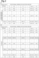
FIG. 3(A) is a diagram illustrating a map for setting the torque rate of a conventional electric motor, andFIG. 3(B) is a diagram illustrating a map for setting the torque rate of an electric motor according to the present embodiment. -
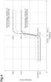
FIG. 4 is a graph illustrating a relationship between a torque and a torque rate by the vehicle control device according to the embodiment. - Hereinafter, a vehicle control device according to an embodiment of one aspect of the present invention will be described in detail with reference to the drawings. As illustrated in
FIG. 1 , avehicle control device 1 of the present embodiment is mounted on anautomobile 100 and controls theautomobile 100 traveling using anelectric motor 2 as a power source. Theautomobile 100 is, for example, a hybrid electric vehicle (HEV), a plug-in hybrid electric vehicle (PHEV), a fuel cell electric vehicle (FCEV), or a battery electric vehicle (BEV) or the like, and is a large vehicle such as a bus or a truck. That is, theautomobile 100 may include an internal combustion engine or the like as a power source in addition to theelectric motor 2. - The
vehicle control device 1 includes acontrol unit 10 configured to control theelectric motor 2. Theelectric motor 2 is, for example, a permanent magnet synchronous motor, and can also generate power. An output shaft of theelectric motor 2 is connected to an input shaft of atransmission 3. An output shaft of thetransmission 3 is connected to left andright drive wheels 7 via apropeller shaft 4, adifferential device 5, and adrive shaft 6. Note that, in a case where theelectric motor 2 is an in-wheel motor incorporated in thedrive wheel 7, thetransmission 3, thepropeller shaft 4, thedifferential device 5, and thedrive shaft 6 may be omitted. Theautomobile 100 includes abattery 8 for supplying electric power to theelectric motor 2. Thebattery 8 supplies electric power to theelectric motor 2 via aninverter 9. Theinverter 9 generates a control signal for rotationally driving theelectric motor 2 on the basis of a command signal from thecontrol unit 10. - The
control unit 10 includes an electronic control unit (ECU). The ECU is an electronic control unit including a central processing unit (CPU), a read only memory (ROM), a random access memory (RAM), and the like. The ECU loads, for example, a program recorded in the ROM into the RAM, and causes the CPU to execute the program loaded into the RAM, thereby implementing various functions. The ECU may include a plurality of electronic units. - When the torque of the
electric motor 2 decreases from a region on a positive side of the torque in a direction in which the torque of theelectric motor 2 accelerates theautomobile 100 to a region on a negative side of the torque in a direction in which the torque of theelectric motor 2 decelerates theautomobile 100, thecontrol unit 10 controls a torque rate as a change rate of the torque per unit time. - When the torque of the
electric motor 2 decreases from the region on the positive side of the torque to the region on the negative side of the torque, for example, accelerator-off regeneration or retarder regeneration is performed. In the accelerator-off regeneration, when an accelerator pedal is turned off, theelectric motor 2 is rotated by the rotational force of thedrive wheel 7 of the inertia-travelingautomobile 100, to cause theelectric motor 2 to generate electric power. In the accelerator-off regeneration, the kinetic energy of theautomobile 100 is converted into electric energy, to change thebattery 8. In the retarder regeneration, a conventional retarder is assumed, and the torque (regenerative torque) of theelectric motor 2 is controlled according to the number of stages of an operation lever to assist the braking of theautomobile 100 at the time of deceleration. - The
vehicle control device 1 of the present embodiment may be applied when the torque of theelectric motor 2 decreases from the region on the positive side of the torque to the region on the negative side of the torque in a system in which the powering torque and regenerative torque of theelectric motor 2 are controlled only by the operation of the accelerator pedal in the acceleration and deceleration of theautomobile 100. In this system, acceleration and deceleration (regeneration) are performed following the opening degree of the accelerator pedal. - In this system, for example, when the accelerator pedal is stepped and turned on, the
electric motor 2 generates the powering torque (torque in the positive region). Meanwhile, in this system, when the accelerator pedal is not stepped and is turned off, theelectric motor 2 generates the regenerative torque (torque in the negative region). In this system, the regenerative region is enlarged, and the regenerative torque can be obtained without waste at the time of deceleration. In this system, even when the accelerator pedal is turned on, theelectric motor 2 may generate the regenerative torque in the region on the negative side when the stepping amount of the accelerator pedal is small, and theelectric motor 2 may generate the regenerative torque in the region on the negative side when the accelerator pedal is turned off. That is, in this system, control including the positive side and negative side of the torque is performed according to the stepping amount of the accelerator pedal. - Hereinafter, the operation of the
vehicle control device 1 of the present embodiment will be described. Conventionally, a torque rate [Nm/s], which is a change rate in the torque per unit time, is set in order to ensure drivability such as the suppression of the occurrence of impact due to a sudden change in the torque of theelectric motor 2. Conventionally, the torque rate is set by the following method in consideration of a factor having a large influence on drivability with respect to a change in the torque of theelectric motor 2. - Conventionally, when the speed of the
automobile 100 is controlled as illustrated inFIG. 2(A) , the torque rate is set based on, for example, the accelerator opening degree (stepping amount of accelerator pedal) [%] and the rotational speed of theelectric motor 2 as illustrated inFIG. 3(A) . Conventionally, the torque rate is set based on the transmission gear ratio (gear number) of thetransmission 3 and the rotational speed of theelectric motor 2. InFIG. 3(A) , Y1 < Y2 < ... < Yi < ... < Y(n-1) < Yn and Z1 < Z2 < ... < Zi < ... < Z(n-1) < Zn are satisfied (n and i are arbitrary natural numbers, and 1 < i < n is satisfied). - Conventionally, as illustrated in the gradient of the graph of
FIG. 2(B) , when the torque of theelectric motor 2 decreases from the region on the positive side of the torque to the region on the negative side of the torque, the torque rate is constant, and the torque rate in the region on the positive side of the torque is equal to the torque rate in the region on the negative side of the torque. For example, inFIG. 3(A) , for the accelerator opening degrees Z1, Z2, ..., Zi, ..., Z(n-1), and Zn with respect to the rotational speed Yi of theelectric motor 2, the torque rates (αi1, αi2, ..., αii, ..., αi(n-1), and αin are set to be constant as αi1 = αi2 = ... = αii = ... = αi(n-1) = αin. - However, in such torque rate setting, priority is given to making a rise of deceleration in the region on the negative side of the torque gentle, and when a small torque rate is set, the driver still feels the acceleration of the
automobile 100 from on to off of the accelerator pedal. That is, the responsiveness is deteriorated. Meanwhile, when a large torque rate is set with priority given to reduction of the feeling that the driver still feels acceleration when the accelerator pedal is turned off on the positive side of the torque, the deceleration rises quickly, and impact is generated. For example, there is a possibility that deterioration of ride comfort, an influence on passengers, and an influence on luggage occur. - A disadvantage of the conventional torque rate setting method is that it is impossible to clearly distinguish between the positive side (acceleration side) of the torque and the negative side (deceleration side) of the torque due to the relationship of the item of the axis of the map of the torque rate being set. Therefore, in the present embodiment, the following two points are performed.
- (1) Change in axis item of map of torque rate
- (2) Optimization of torque rate value
- As a change in the axis item of the torque rate map of (1), in the present embodiment, as illustrated by boldface in
FIG. 3(B) , by changing the axis item of the torque rate map to the rotational speed and the torque of theelectric motor 2, it is possible to clearly separate the positive side of the torque from the negative side of the torque. InFIG. 3(B) , X1 < X2 < ... < X(i-K) < ... < Xi < ... < X(i+L) < ... < X(n-1) < Xn is satisfied (n, i, K, and L are arbitrary natural numbers, and 1 < i < n, 1 < K < i-1, and 1 < L < n-i are satisfied). Xi = 0 is satisfied. X1 < X2 < ... < X(i-K) < ... < Xi is in the region on the negative side of the torque, and Xi < ... < X(i+L) < ... < X(n-1) < Xn is in the region on the positive side of the torque. - As the optimization of the torque rate value in (2), in the present embodiment, as illustrated in
FIGS. 2(C), 2(D) , and3(B) , when the torque of theelectric motor 2 decreases from the region on the positive side of the torque to the region on the negative side of the torque, thecontrol unit 10 controls theelectric motor 2 so that the torque rate in the region on the negative side of the torque is smaller than the torque rate in the region on the positive side of the torque. For example, in the example ofFIG. 2(D) , when the torque of theelectric motor 2 decreases from the region on the positive side of the torque to the region on the negative side of the torque, the torque rate represented by the gradient of the graph is smaller in the region on the negative side of the torque than in the region on the positive side of the torque. That is, the gradient of the graph is gentle. - For example, in
FIG. 3(B) , the torque rates βi1, βi2, ..., βi(i-K), ..., βii, ..., βi(i+L), ... βi(n-1), and βin for the torques X1, X2, ..., X(i-K), ..., Xi, ..., X(i+L), ..., X(n-1), and Xn with respect to the rotational speed Yi of theelectric motor 2 are such that the torque rates βi1, βi2, ..., and βi(i-K) in the regions Xi > .... > X(i-K) > ... > X2 > X1 on the negative side of the torque are smaller than the torque rates βi(i+L), ..., βi(n-1), and βin in the regions Xi < ... <X(i+L) < ... < X(n-1) < Xn on the positive side of the torque. - The torque rates βi1, βi2, ..., βi(i-K), ..., βii, ..., βi(i+L), ... βi(n-1), and βin for the torques X1, X2, ..., X(i-K), ..., Xi, ..., X(i+L), ..., X(n-1), and Xn with respect to the rotational speed Yi of the
electric motor 2 satisfy βi1 ≤ βi2 ≤ ... ≤ βi(i-K) ≤ ... ≤ βii ≤ ... ≤ βi(i+L) ≤ ... ≤ βi(n-1) ≤ βin, and the torque rate decreases as the torque decreases. In X1, X2, ..., X(i-K), ..., Xi, ..., X(i+L), ..., X(n-1), and Xn, which are torque regions, the torque rate may decrease as a whole with respect to the decrease in the torque, and there may be a region where the torque rate is constant with respect to the decrease in the torque in part. - In the present embodiment, furthermore, the
control unit 10 controls theelectric motor 2 so that the torque rate decreases as the torque approaches 0 in the region on the positive side of the torque when the torque of theelectric motor 2 decreases from the region on the positive side of the torque to the region on the negative side of the torque, and the torque rate increases as the torque approaches 0 in the region on the negative side of the torque. As illustrated in a portion surrounded by a thick line inFIGS. 2(D) and3(B) , the torque rate decreases as the torque approaches 0 in the regions Xi < ... < X(i+L) on the positive side of the torque, and the torque rate increases as the torque approaches 0 in the regions Xi > ... > X(i-K) on the negative side of the torque. The fluctuation of the torque rate when the torque is near 0 is reduced. - In
FIG. 3(B) , in the regions Xi < ... < X(i+L) on the positive side of the torque, βii ≤ βi(i+1) ≤ βi(i+2) ≤ ... ≤ βi(i+(L-1)) ≤ Xi(i+L) is satisfied, and the torque rate decreases as the torque approaches 0. In the regions Xi < ... < X(i+L) on the positive side of the torque, it is sufficient that the torque rate decreases as the torque approaches 0 as a whole, and there may be a region where the torque rate is constant with respect to the decrease of the torque in part. In the regions Xi > ... > X(i-K) on the negative side of the torque, βii ≥ βi(i-1) ≥ βi(i-2) ≥ ... > βi(i-(K-1)) ≥ βi(i-K) is satisfied, and the torque rate increases as the torque approaches 0. In the regions Xi > ... > X(i-K) on the negative side of the torque, it is sufficient that the torque rate increases as the torque approaches 0 as a whole, and there may be a region where the torque rate is constant with respect to the increase of the torque in part. - Therefore, in the present embodiment, when the torque is near 0, the
control unit 10 controls theelectric motor 2 according to the graph as illustrated inFIG. 4 . In the example ofFIG. 4 , β1i which is a torque rate when the torque is 0 in the case where the rotational speed of the electric motor is Y1 is equal to β21 which is a torque rate when the torque is the minimum value on the negative side in the case where the rotational speed of the electric motor is Y2. However, this is an example, and the torque rate can take any value. - In the examples of
FIGS. 3(B) and4 , when the torque of theelectric motor 2 decreases from the region on the positive side of the torque to the region on the negative side of the torque, thecontrol unit 10 controls theelectric motor 2 so that the torque rate in the region on the negative side of the torque is smaller than the torque rate in the region on the positive side of the torque. However, in the region of X(i-K) < ... < Xi < ... < X(i+L) including the case where the torque is 0, as indicated by a broken line inFIG. 4 , the torque rate in the region on the positive side of the torque is equal to the torque rate in the region on the negative side of the torque, and the torque rate may fluctuate stepwise. - That is, a case where the torque rate in the region on the negative side of the torque is smaller than the torque rate in the region on the positive side of the torque includes a case where the torque rate in the region on the positive side of the torque is equal to the torque rate in the region on the negative side of the torque in arbitrary regions of X(i-K) < ... < Xi < ... < X(i+L) including a case where the torque is 0.
- As a basic idea, in the present embodiment, when the torque of the
electric motor 2 decreases from the region on the positive side of the torque to the region on the negative side of the torque, an intermediate layer in which the torque rate fluctuates from a large value to a small value is as close as possible to a portion where the torque of theelectric motor 2 is 0 [Nm]. As a result, it is possible to suppress the driver from having a feeling of the acceleration of the automobile and impact. As a whole, the torque rate in the region on the negative side of the torque can be determined from the viewpoint of preventing the falling of the standing passenger, for example, in a case where theautomobile 100 is a bus, and can be determined from the viewpoint of preventing the collapse of cargo in a case where theautomobile 100 is a truck. - In the present embodiment, the
vehicle control device 1 configured to control theautomobile 100 traveling with theelectric motor 2 as the power source includes thecontrol unit 10 configured to control theelectric motor 2, wherein when the torque of theelectric motor 2 decreases from the region on the positive side of the torque in the direction in which the torque of theelectric motor 2 accelerates theautomobile 100 to the region on the negative side of the torque in the direction in which the torque of theelectric motor 2 decelerates theautomobile 100, thecontrol unit 10 controls theelectric motor 2 so that the torque rate in the region on the negative side of the torque is smaller than the torque rate in the region on the positive side of the torque, the torque rate being the change rate of the torque per unit time. - Since the torque rate in the region on the positive side of the torque is relatively large, it is possible to reduce deterioration of responsiveness in which the driver of the
automobile 100 still feels the acceleration of theautomobile 100 when the driver performs a deceleration operation. Meanwhile, since the torque rate in the region on the negative side of the torque is relatively small, it is possible to reduce impact caused by an early rise of deceleration when the driver of theautomobile 100 performs a deceleration operation. Therefore, both ensuring of responsiveness and reduction of impact can be achieved. By ensuring the responsiveness, drivability can be improved. - In the present embodiment, the
control unit 10 controls theelectric motor 2 so that the torque rate is relatively large in the region on the positive side of the torque, but decreases as the torque approaches 0 when the torque of theelectric motor 2 decreases from the region on the positive side of the torque to the region on the negative side of the torque, and the torque rate is relatively small in the region on the negative side of the torque, but increases as the torque approaches 0. Therefore, when the torque is near 0, which is the boundary between the region on the positive side of the torque and the region on the negative side of the torque, the fluctuation of the torque rate becomes smooth, and the influence on the behavior of theautomobile 100 can be reduced. - Although the embodiment of one aspect of the present invention has been described above, one aspect of the present invention is not limited to the above embodiment and is implemented in various forms.
-
- 1
- vehicle control device
- 2
- electric motor
- 3
- transmission
- 4
- propeller shaft
- 5
- differential device
- 6
- drive shaft
- 7
- drive wheel
- 8
- battery
- 9
- inverter
- 10
- control unit
- 100
- automobile
Claims (2)
- A vehicle control device configured to control an automobile traveling with an electric motor as a power source, the vehicle control device comprisinga control unit configured to control the electric motor,wherein when a torque of the electric motor decreases from a region on a positive side of the torque in a direction in which the torque of the electric motor accelerates the automobile to a region on a negative side of the torque in a direction in which the torque of the electric motor decelerates the automobile,the control unit controls the electric motor so that a torque rate in the region on the negative side of the torque is smaller than the torque rate in the region on the positive side of the torque, the torque rate being a change rate of the torque per unit time.
- The vehicle control device according to claim 1, whereinwhen the torque of the electric motor decreases from the region on the positive side of the torque to the region on the negative side of the torque,the control unit controls the electric motor so thatthe torque rate decreases as the torque approaches 0 in the region on the positive side of the torque, andthe torque rate increases as the torque approaches 0 in the region on the negative side of the torque.
Applications Claiming Priority (2)
| Application Number | Priority Date | Filing Date | Title |
|---|---|---|---|
| JP2021163850A JP2023054888A (en) | 2021-10-05 | 2021-10-05 | vehicle controller |
| PCT/JP2022/037087 WO2023058639A1 (en) | 2021-10-05 | 2022-10-04 | Vehicle control device |
Publications (2)
| Publication Number | Publication Date |
|---|---|
| EP4414205A1 true EP4414205A1 (en) | 2024-08-14 |
| EP4414205A4 EP4414205A4 (en) | 2025-11-05 |
Family
ID=85803475
Family Applications (1)
| Application Number | Title | Priority Date | Filing Date |
|---|---|---|---|
| EP22878507.7A Pending EP4414205A4 (en) | 2021-10-05 | 2022-10-04 | VEHICLE CONTROL DEVICE |
Country Status (5)
| Country | Link |
|---|---|
| US (1) | US20240399892A1 (en) |
| EP (1) | EP4414205A4 (en) |
| JP (1) | JP2023054888A (en) |
| CN (1) | CN118159442A (en) |
| WO (1) | WO2023058639A1 (en) |
Family Cites Families (30)
| Publication number | Priority date | Publication date | Assignee | Title |
|---|---|---|---|---|
| JP3775012B2 (en) * | 1997-08-29 | 2006-05-17 | アイシン・エィ・ダブリュ株式会社 | Hybrid drive device for vehicle |
| US6554088B2 (en) * | 1998-09-14 | 2003-04-29 | Paice Corporation | Hybrid vehicles |
| US6672415B1 (en) * | 1999-05-26 | 2004-01-06 | Toyota Jidosha Kabushiki Kaisha | Moving object with fuel cells incorporated therein and method of controlling the same |
| US6827167B2 (en) * | 2002-03-28 | 2004-12-07 | Ford Global Technologies, Llc | Hybrid electric vehicle torque distribution |
| US6629026B1 (en) * | 2002-04-12 | 2003-09-30 | Ford Motor Company | Hybrid electric vehicle with motor torque fill in |
| JP3951957B2 (en) * | 2003-04-16 | 2007-08-01 | トヨタ自動車株式会社 | POWER OUTPUT DEVICE, ITS CONTROL METHOD, AND VEHICLE |
| JP4458300B2 (en) * | 2007-10-25 | 2010-04-28 | 本田技研工業株式会社 | Electric vehicle and regeneration control method for electric vehicle |
| JP4495234B2 (en) * | 2008-07-31 | 2010-06-30 | 富士通テン株式会社 | Fuel saving driving diagnosis device, fuel saving driving diagnosis system and fuel saving driving diagnosis method |
| US8068948B2 (en) * | 2009-05-29 | 2011-11-29 | GM Global Technology Operations LLC | Method for controlling multiple EVT shifts in a multi-mode hybrid transmission |
| JP5516081B2 (en) * | 2010-05-31 | 2014-06-11 | 日産自動車株式会社 | Torque response control device for electric motor for vehicle |
| JP5514661B2 (en) * | 2010-07-23 | 2014-06-04 | 株式会社日立製作所 | Drive control device for electric vehicle |
| JP5492745B2 (en) * | 2010-11-16 | 2014-05-14 | 株式会社日立製作所 | Electric vehicle traveling control device |
| CN117048579A (en) * | 2011-01-13 | 2023-11-14 | 卡明斯公司 | Systems, methods, and apparatus for controlling power output distribution in a hybrid powertrain |
| EP2727786B1 (en) * | 2011-07-01 | 2019-05-15 | Jatco Ltd | Device for controlling hybrid vehicle |
| US9308831B2 (en) * | 2012-04-27 | 2016-04-12 | GM Global Technology Operations LLC | System and method for controlling vehicle creep torque |
| US9227525B2 (en) * | 2013-10-14 | 2016-01-05 | Deere & Company | Method and system for controlling torque in an electric drive powertrain |
| US20160090005A1 (en) * | 2014-03-10 | 2016-03-31 | Dean Drako | Distributed Torque Generation System and Method of Control |
| JP6102862B2 (en) * | 2014-08-22 | 2017-03-29 | 株式会社デンソー | Rotating electrical machine control device |
| KR101558812B1 (en) * | 2014-09-24 | 2015-10-07 | 현대자동차주식회사 | Motor torque control method in coasting state of hybrid electric vehicle |
| JP6146396B2 (en) * | 2014-11-14 | 2017-06-14 | トヨタ自動車株式会社 | Vehicle driven by electric motor and method for controlling the vehicle |
| JP6548601B2 (en) * | 2016-03-28 | 2019-07-24 | 株式会社クボタ | Work vehicle |
| US9764658B1 (en) * | 2016-06-21 | 2017-09-19 | Proterra Inc. | Electric motor control by torque perturbation |
| JP6870688B2 (en) * | 2017-01-24 | 2021-05-12 | 日産自動車株式会社 | Vehicle control device and control method |
| JP7102781B2 (en) * | 2018-02-28 | 2022-07-20 | 株式会社デンソー | Control device |
| US11167745B2 (en) * | 2018-04-19 | 2021-11-09 | Toyota Jidosha Kabushiki Kaisha | Control system of hybrid vehicle |
| CN110386128B (en) * | 2018-04-20 | 2022-05-27 | 丰田自动车株式会社 | Electric vehicle |
| CN110682798B (en) * | 2018-07-05 | 2023-08-18 | 蔚来(安徽)控股有限公司 | Motor torque control method, device, system and computer storage medium |
| US11177762B2 (en) * | 2019-02-20 | 2021-11-16 | Volvo Car Corporation | Electric motor control for preventing torque ripple |
| US10960882B2 (en) * | 2019-06-18 | 2021-03-30 | Ford Global Technologies, Llc | Method and system for creep torque control |
| JP7382841B2 (en) | 2020-01-22 | 2023-11-17 | 株式会社Subaru | vehicle |
-
2021
- 2021-10-05 JP JP2021163850A patent/JP2023054888A/en active Pending
-
2022
- 2022-10-04 US US18/698,041 patent/US20240399892A1/en active Pending
- 2022-10-04 WO PCT/JP2022/037087 patent/WO2023058639A1/en not_active Ceased
- 2022-10-04 EP EP22878507.7A patent/EP4414205A4/en active Pending
- 2022-10-04 CN CN202280064896.2A patent/CN118159442A/en active Pending
Also Published As
| Publication number | Publication date |
|---|---|
| JP2023054888A (en) | 2023-04-17 |
| WO2023058639A1 (en) | 2023-04-13 |
| US20240399892A1 (en) | 2024-12-05 |
| CN118159442A (en) | 2024-06-07 |
| EP4414205A4 (en) | 2025-11-05 |
Similar Documents
| Publication | Publication Date | Title |
|---|---|---|
| EP1981729B1 (en) | Control device for vehicle, and control method thereof | |
| EP3683078B1 (en) | Control system to eliminate powertrain backlash | |
| US8897982B2 (en) | Method for driving a hybrid vehicle in a load reversal | |
| US11738755B2 (en) | Vehicle controlling apparatus | |
| CN110816281B (en) | Control unit, device and method for vehicle regenerative braking control | |
| CN110386128B (en) | Electric vehicle | |
| US12397795B2 (en) | Regenerative braking control system and method using paddle shift of hybrid vehicle | |
| US10752288B2 (en) | Lateral motion control for cornering and regenerative braking energy capture | |
| EP3984845A1 (en) | Electric device control method and electric device | |
| JP2017159837A (en) | Vehicle control device | |
| JP2007129827A (en) | Intelligent brake assist system for hybrid vehicles | |
| CN106064615B (en) | The control device of hybrid vehicle | |
| JP7176360B2 (en) | electric vehicle | |
| US20240399892A1 (en) | Vehicle control device | |
| JP2011125089A (en) | Controller for vehicle driving motors | |
| US12194891B2 (en) | Electrified vehicle and regenerative braking control method of the same | |
| US20240067079A1 (en) | Vehicle including electric motor and method of controlling brake lamp for the same | |
| JP7392741B2 (en) | Vehicle controls and vehicles | |
| JP7385464B2 (en) | Vehicle control device | |
| US20240278653A1 (en) | Vehicle system | |
| EP4493439B1 (en) | A control system for controlling a retardation of a vehicle | |
| JP3894049B2 (en) | Hybrid vehicle and its control device | |
| JP2021030835A (en) | Brake force control apparatus | |
| JP2021115968A (en) | Hybrid-vehicular control apparatus | |
| KR20160056527A (en) | Torque Intervention System For Hybrid Electric Vehicle |
Legal Events
| Date | Code | Title | Description |
|---|---|---|---|
| STAA | Information on the status of an ep patent application or granted ep patent |
Free format text: STATUS: THE INTERNATIONAL PUBLICATION HAS BEEN MADE |
|
| PUAI | Public reference made under article 153(3) epc to a published international application that has entered the european phase |
Free format text: ORIGINAL CODE: 0009012 |
|
| STAA | Information on the status of an ep patent application or granted ep patent |
Free format text: STATUS: REQUEST FOR EXAMINATION WAS MADE |
|
| 17P | Request for examination filed |
Effective date: 20240416 |
|
| AK | Designated contracting states |
Kind code of ref document: A1 Designated state(s): AL AT BE BG CH CY CZ DE DK EE ES FI FR GB GR HR HU IE IS IT LI LT LU LV MC ME MK MT NL NO PL PT RO RS SE SI SK SM TR |
|
| DAV | Request for validation of the european patent (deleted) | ||
| DAX | Request for extension of the european patent (deleted) | ||
| A4 | Supplementary search report drawn up and despatched |
Effective date: 20251007 |
|
| RIC1 | Information provided on ipc code assigned before grant |
Ipc: B60L 15/20 20060101AFI20250930BHEP |