EP4414199A1 - Improved tank for a work vehicle - Google Patents
Improved tank for a work vehicle Download PDFInfo
- Publication number
- EP4414199A1 EP4414199A1 EP23306307.2A EP23306307A EP4414199A1 EP 4414199 A1 EP4414199 A1 EP 4414199A1 EP 23306307 A EP23306307 A EP 23306307A EP 4414199 A1 EP4414199 A1 EP 4414199A1
- Authority
- EP
- European Patent Office
- Prior art keywords
- tank
- urea
- fuel tank
- along
- arrangement
- Prior art date
- Legal status (The legal status is an assumption and is not a legal conclusion. Google has not performed a legal analysis and makes no representation as to the accuracy of the status listed.)
- Granted
Links
Images


Classifications
-
- B—PERFORMING OPERATIONS; TRANSPORTING
- B60—VEHICLES IN GENERAL
- B60K—ARRANGEMENT OR MOUNTING OF PROPULSION UNITS OR OF TRANSMISSIONS IN VEHICLES; ARRANGEMENT OR MOUNTING OF PLURAL DIVERSE PRIME-MOVERS IN VEHICLES; AUXILIARY DRIVES FOR VEHICLES; INSTRUMENTATION OR DASHBOARDS FOR VEHICLES; ARRANGEMENTS IN CONNECTION WITH COOLING, AIR INTAKE, GAS EXHAUST OR FUEL SUPPLY OF PROPULSION UNITS IN VEHICLES
- B60K15/00—Arrangement in connection with fuel supply of combustion engines or other fuel consuming energy converters, e.g. fuel cells; Mounting or construction of fuel tanks
- B60K15/03—Fuel tanks
-
- B—PERFORMING OPERATIONS; TRANSPORTING
- B60—VEHICLES IN GENERAL
- B60K—ARRANGEMENT OR MOUNTING OF PROPULSION UNITS OR OF TRANSMISSIONS IN VEHICLES; ARRANGEMENT OR MOUNTING OF PLURAL DIVERSE PRIME-MOVERS IN VEHICLES; AUXILIARY DRIVES FOR VEHICLES; INSTRUMENTATION OR DASHBOARDS FOR VEHICLES; ARRANGEMENTS IN CONNECTION WITH COOLING, AIR INTAKE, GAS EXHAUST OR FUEL SUPPLY OF PROPULSION UNITS IN VEHICLES
- B60K13/00—Arrangement in connection with combustion air intake or gas exhaust of propulsion units
- B60K13/04—Arrangement in connection with combustion air intake or gas exhaust of propulsion units concerning exhaust
-
- B—PERFORMING OPERATIONS; TRANSPORTING
- B60—VEHICLES IN GENERAL
- B60K—ARRANGEMENT OR MOUNTING OF PROPULSION UNITS OR OF TRANSMISSIONS IN VEHICLES; ARRANGEMENT OR MOUNTING OF PLURAL DIVERSE PRIME-MOVERS IN VEHICLES; AUXILIARY DRIVES FOR VEHICLES; INSTRUMENTATION OR DASHBOARDS FOR VEHICLES; ARRANGEMENTS IN CONNECTION WITH COOLING, AIR INTAKE, GAS EXHAUST OR FUEL SUPPLY OF PROPULSION UNITS IN VEHICLES
- B60K15/00—Arrangement in connection with fuel supply of combustion engines or other fuel consuming energy converters, e.g. fuel cells; Mounting or construction of fuel tanks
- B60K15/03—Fuel tanks
- B60K15/077—Fuel tanks with means modifying or controlling distribution or motion of fuel, e.g. to prevent noise, surge, splash or fuel starvation
-
- B—PERFORMING OPERATIONS; TRANSPORTING
- B60—VEHICLES IN GENERAL
- B60K—ARRANGEMENT OR MOUNTING OF PROPULSION UNITS OR OF TRANSMISSIONS IN VEHICLES; ARRANGEMENT OR MOUNTING OF PLURAL DIVERSE PRIME-MOVERS IN VEHICLES; AUXILIARY DRIVES FOR VEHICLES; INSTRUMENTATION OR DASHBOARDS FOR VEHICLES; ARRANGEMENTS IN CONNECTION WITH COOLING, AIR INTAKE, GAS EXHAUST OR FUEL SUPPLY OF PROPULSION UNITS IN VEHICLES
- B60K15/00—Arrangement in connection with fuel supply of combustion engines or other fuel consuming energy converters, e.g. fuel cells; Mounting or construction of fuel tanks
- B60K15/03—Fuel tanks
- B60K2015/03105—Fuel tanks with supplementary interior tanks inside the fuel tank
-
- B—PERFORMING OPERATIONS; TRANSPORTING
- B60—VEHICLES IN GENERAL
- B60K—ARRANGEMENT OR MOUNTING OF PROPULSION UNITS OR OF TRANSMISSIONS IN VEHICLES; ARRANGEMENT OR MOUNTING OF PLURAL DIVERSE PRIME-MOVERS IN VEHICLES; AUXILIARY DRIVES FOR VEHICLES; INSTRUMENTATION OR DASHBOARDS FOR VEHICLES; ARRANGEMENTS IN CONNECTION WITH COOLING, AIR INTAKE, GAS EXHAUST OR FUEL SUPPLY OF PROPULSION UNITS IN VEHICLES
- B60K15/00—Arrangement in connection with fuel supply of combustion engines or other fuel consuming energy converters, e.g. fuel cells; Mounting or construction of fuel tanks
- B60K15/03—Fuel tanks
- B60K2015/03118—Multiple tanks, i.e. two or more separate tanks
- B60K2015/03144—Fluid connections between the tanks
-
- B—PERFORMING OPERATIONS; TRANSPORTING
- B60—VEHICLES IN GENERAL
- B60K—ARRANGEMENT OR MOUNTING OF PROPULSION UNITS OR OF TRANSMISSIONS IN VEHICLES; ARRANGEMENT OR MOUNTING OF PLURAL DIVERSE PRIME-MOVERS IN VEHICLES; AUXILIARY DRIVES FOR VEHICLES; INSTRUMENTATION OR DASHBOARDS FOR VEHICLES; ARRANGEMENTS IN CONNECTION WITH COOLING, AIR INTAKE, GAS EXHAUST OR FUEL SUPPLY OF PROPULSION UNITS IN VEHICLES
- B60K15/00—Arrangement in connection with fuel supply of combustion engines or other fuel consuming energy converters, e.g. fuel cells; Mounting or construction of fuel tanks
- B60K15/03—Fuel tanks
- B60K2015/03118—Multiple tanks, i.e. two or more separate tanks
- B60K2015/03151—Mechanical connection between the tanks
-
- B—PERFORMING OPERATIONS; TRANSPORTING
- B60—VEHICLES IN GENERAL
- B60K—ARRANGEMENT OR MOUNTING OF PROPULSION UNITS OR OF TRANSMISSIONS IN VEHICLES; ARRANGEMENT OR MOUNTING OF PLURAL DIVERSE PRIME-MOVERS IN VEHICLES; AUXILIARY DRIVES FOR VEHICLES; INSTRUMENTATION OR DASHBOARDS FOR VEHICLES; ARRANGEMENTS IN CONNECTION WITH COOLING, AIR INTAKE, GAS EXHAUST OR FUEL SUPPLY OF PROPULSION UNITS IN VEHICLES
- B60K15/00—Arrangement in connection with fuel supply of combustion engines or other fuel consuming energy converters, e.g. fuel cells; Mounting or construction of fuel tanks
- B60K15/03—Fuel tanks
- B60K2015/03118—Multiple tanks, i.e. two or more separate tanks
- B60K2015/03157—Multiple tanks, i.e. two or more separate tanks for supply different types of fuel to the motor
-
- B—PERFORMING OPERATIONS; TRANSPORTING
- B60—VEHICLES IN GENERAL
- B60K—ARRANGEMENT OR MOUNTING OF PROPULSION UNITS OR OF TRANSMISSIONS IN VEHICLES; ARRANGEMENT OR MOUNTING OF PLURAL DIVERSE PRIME-MOVERS IN VEHICLES; AUXILIARY DRIVES FOR VEHICLES; INSTRUMENTATION OR DASHBOARDS FOR VEHICLES; ARRANGEMENTS IN CONNECTION WITH COOLING, AIR INTAKE, GAS EXHAUST OR FUEL SUPPLY OF PROPULSION UNITS IN VEHICLES
- B60K15/00—Arrangement in connection with fuel supply of combustion engines or other fuel consuming energy converters, e.g. fuel cells; Mounting or construction of fuel tanks
- B60K15/03—Fuel tanks
- B60K2015/03164—Modular concepts for fuel tanks
-
- B—PERFORMING OPERATIONS; TRANSPORTING
- B60—VEHICLES IN GENERAL
- B60Y—INDEXING SCHEME RELATING TO ASPECTS CROSS-CUTTING VEHICLE TECHNOLOGY
- B60Y2200/00—Type of vehicle
- B60Y2200/20—Off-Road Vehicles
- B60Y2200/22—Agricultural vehicles
- B60Y2200/221—Tractors
Definitions
- the present invention relates to a tank for an agricultural engine such as a tractor.
- a fuel tank assembly which comprises a fuel tank and a urea tank.
- the fuel tank comprises a lower portion which forms a basis, and an upper portion of reduced width.
- the urea tank is then arranged side by side with the fuel tank.
- Such a configuration is conventionally used to ensure an easy filling of both tanks.
- issues can occur when emptying the urea tank after use, as the flow is limited by the arrangement of the urea tank and the fuel tank.
- the present invention aims at providing a solution these technical issues.
- the present invention relates to a tank arrangement comprising a fuel tank and a urea tank,
- the urea tank comprises a urea drain on a lower portion of the urea tank along the vertical direction, the tank arrangement being configured such that so that fluid flowing from the urea drain can be discharged along the vertical direction without flowing on the tank arrangement.
- the tank arrangement further comprises a tank support arranged below the fuel tank and the urea tank along the vertical direction, wherein the tank support is provided with a notch, such that the urea drain is in front of said notch when the urea tank is in the engaged configuration within the fuel tank.
- the notch extends from a front face of the tank support (300) of the fuel tank.
- the notch and the urea drain are arranged so that fluid flowing from the urea drain can be discharged without flowing on the tank support.
- the secondary portion of the fuel tank comprises a base portion, formed such that in the engaged configuration, the urea tank is arranged between the base portion and the upper portion along the vertical direction, wherein the base portion of the fuel tank is provided with a notch, such that the urea drain is in front of said notch when the urea tank is in the engaged configuration within the fuel tank.
- the notch extends from a front face of the base portion of the fuel tank, and extends through the base portion along the vertical direction.
- the notch and the urea drain are arranged so that fluid flowing from the urea drain can be discharged without flowing on the base portion of the fuel tank.
- the tank support comprises lateral abutments , adapted to form an abutment along the rear-front direction.
- the urea tank comprises a urea inlet on an upper face of the urea tank, said urea inlet being configured to be connected to ducts and/or lines through the through hole formed on the secondary portion of the fuel tank.
- the upper portion of the fuel tank presents a recess adapted to house a toolbox.
- the recess is configured so that a toolbox inserted in the recess does not protrude over the upper portion of the fuel tank along the vertical direction.
- the tank arrangement further comprises a lock adapted to immobilize the urea tank in the engaged configuration within the housing of the fuel tank.
- the intermediate portion of the fuel tank presents a shoulder portion and the urea tank presents a stepped portion adapted to fit under the shoulder portion in the engaged configuration.
- the fuel tank and the urea tank comprise guiding means adapted to guide the insertion of the urea tank within the housing defined by the fuel tank.
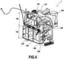
- FIGS 1 to 4 present a tank arrangement 1 for a work vehicle according to an example embodiment of the invention.
- This tank arrangement can for instance be implemented on a work vehicle such as a tractor, or more generally on an agricultural engine.
- the tank arrangement 1 as presented comprises a fuel tank 100 and a urea tank 200, that are distinct from each other.
- the fuel tank 100 as presented comprises a fuel tank body 110 which presents a main portion 102 and a secondary portion 104.
- the secondary portion 104 comprises an upper portion and an intermediate portion 130 140, that are arranged successively from a top to a bottom along a vertical direction.
- the fuel tank body 110 presents an inner volume adapted to store fuel.
- the fuel tank body extends along a main direction X-X which is defined as corresponding to a front-rear direction for a work vehicle.
- a vertical direction is defined as the vertical axis Z-Z
- a width direction Y-Y is defined as perpendicular to both the vertical direction Z-Z and the main direction X-X.
- a front face of the fuel tank 100 is defined along the width direction, which is designed to be the face of the fuel tank that faces an exterior side of the work vehicle.
- the main portion 102 and the secondary portion 104 are arranged successively along the main direction X-X.
- the tank arrangement 1 when implemented on a tractor, the tank arrangement 1 is typically arranged in a midway portion of a main body of the tractor, between the engine compartment and the tractor cab, so that the main direction X-X of the fuel tank body corresponds to the front-rear direction of the tractor, the width direction Y-Y corresponds to the transverse direction of the tractor; and the front face of the fuel tank 100 protrudes from a lateral side of the tractor.
- the fuel tank body 110 is provided with a fuel inlet 142 on its front face or on an upper face, typically on the front face or on an upper face of the upper portion 140, said fuel inlet being adapted to enable to fill the fuel tank 100 with fuel.
- the secondary portion 104 of the fuel tank body 110 is configured so as to define a housing adapted to receive the urea tank 200.
- the housing is typically defined by the intermediate portion 130.
- the fuel tank body 110 is typically defined such that the intermediate portion presents a recess defining the housing adapted to accommodate the urea tank 200.
- the housing opens on the front face of the fuel tank 100.
- the housing is defined such that the urea tank can be inserted below the upper portion 140 along the vertical direction Z-Z, in front of the intermediate portion 130 along the width direction Y-Y, and side-by-side with the main portion 102 of the fuel tank 100 along the main direction X-X.
- the urea tank 200 is adapted to be inserted within the housing defined by the fuel tank 100, typically by sliding along the width direction of the fuel tank 100, from the front face of the fuel tank 100.
- the urea tank 200 can therefore be engaged within the housing of the fuel tank 100.
- an engaged configuration of the urea tank 200 within the fuel tank 100 as a configuration where the urea tank 200 is fully engaged within the housing of the fuel tank 100, i.e. the urea tank 200 abuts against the intermediate portion 130 of the fuel tank 100 along the width direction Y-Y.
- the fuel tank 100 typically comprising guiding means adapted to guide the displacement of the urea tank 200 within the housing provided by the fuel tank 100.
- the urea tank 200 presents a shape that is adapted to be engaged within the housing provided by the fuel tank 100.
- the shape of the urea tank 200 is typically complementary to the shape of the housing defined by the fuel tank 100.
- the shape represented in the figures is however only meant to be an example embodiment, and should not be interpreted as limiting the scope of the present invention.
- the urea tank 200 typically presents a urea inlet provided in a top portion of a front face of the urea tank 200.
- the urea inlet 202 is provided on a biased portion between a front face and a top face of the urea tank.
- the urea inlet 202 is adapted to enable the filling of the urea tank 200.
- the urea tank 200 is provided with plug assembly 210 which is here provided on the top face of the urea tank 200, this plug assembly 210 being configured to connect the urea tank 200 to a control unit and to an engine of the work vehicle.
- the upper portion 140 of the fuel tank 100 is typically provided with a groove 144 to accommodate the plug assembly 210 when the urea tank 200 is inserted within the housing of the fuel tank 100, and to accommodate connectors adapted to be connected to the plug assembly 210.
- the groove 144 extends through the width of the fuel tank 100 along the width direction Y-Y so as to define a through hole. Ducts, piles and connectors can then extend through the fuel tank 100 to be connected to the plug assembly 210 of the urea tank 200.
- a groove cover 146 can be arranged on an outer lateral side of the groove 144, so as to protect the plug assembly 210 and the various ducts and pipes arranged within the groove 144 from outer elements and projections.
- the groove cover 146 as illustrated is formed so as to cover the groove 144 while being located behind the urea inlet 202.
- the tank arrangement 1 is typically provided with a lock 20, adapted to lock the urea tank 200 in position within the housing of the fuel tank 100 when the urea tank 200 is in the engaged configuration.
- the lock 20 is provided on the front face of the urea tank 200 and on the front face of the fuel tank 100. This embodiment is only meant as an example, and one can understand that the lock 20 can be located in any appropriate location that can be easily reached by an operator, and that the tank arrangement 1 can be provided with one or more of such locks 20 that can be identical or distinct.
- the lock 20 comprises tabs that are assembled to both the fuel tank 100 and the urea tank 200 with engaging means such as screws.
- the urea tank 200 is provided with a drain 220, arranged on a bottom side of the urea tank 200.
- the drain 220 is adapted to enable an operator to empty the contents of the urea tank 200.
- the drain 220 is typically arranged proximal to the front face of the urea tank 200, so as to be easily reachable by an operator. According to an example embodiment, the drain 220 is located within 20 cm of the front face of the urea tank 200, or typically within 10 cm of the front face of the urea tank 200.
- a tank support 300 is provided under the tank arrangement 1 along the vertical direction Z-Z.
- the tank arrangement 1 is therefore supported by the tank support 300.
- the tank support 300 is provided with a notch 322 formed so that the urea drain 220 is in front of the notch 322 when the urea tank is in the engaged configuration within the housing defined by the fuel tank 100.
- the notch 322 extends through the whole thickness of the tank support 300 along the vertical direction Z-Z, such that when urea flows from the drain 220, urea can flow through the fuel tank 100 without coming in contact with tank support 300.
- urea can be directly discharged from the drain 220 of the urea tank 200 to the ground or to a receptacle without flowing on the tank support 300.
- Such a configuration enables to increase the flow and therefore speed up the draining operation of the urea tank 200 while the urea tank 200 remains engaged within the housing of the fuel tank 100.
- the tank support 300 comprises lateral abutments 310, adapted to form an abutment along the rear-front direction X-X.
- the abutments 310 are adapted to prevent the tank arrangement 1 to move forward along the rear-front direction X-X for instance in case of a sudden stop of a work vehicle. Similar abutments can also be provided to prevent a backward displacement along the rear-front direction X-X in case of sudden acceleration.
- the tank support 300 can comprise abutments adapted to prevent the displacement of the tank arrangement 1 along the main direction X-X, i.e. the front-rear direction X-X.
- the upper portion 140 of the fuel tank 100 presents a recess 145 adapted to house a toolbox.
- This recess 145 is configured so that a toolbox can be fit within, while a top portion of the toolbox will not protrude from the upper portion 140 of the fuel tank 100 along the vertical direction Z-Z.
- Such a configuration enables to house a toolbox while preventing a potential interference with implements of the work vehicle such as a front loader.
- the position of the toolbox is lowered, which enables to increase the visibility for the driver.
- the toolbox can be maintained in position by the shape of the recess 145, and can be directly opened by an operator without having to remove it from the recess 145, which facilitated the use of the toolbox.
- the secondary portion 104 of the fuel tank 100 comprises a base portion 120 formed under the intermediate portion 130 along the vertical direction Z-Z.
- the housing to accommodate the urea tank 200 is therefore defined between the base portion 120 and the upper portion 140 along the vertical direction Z-Z.
- the base portion 120 is arranged on and supported by the tank support 300.
- the base portion 120 of the fuel tank 100 is provided with a notch 122 adapted to be in line with the drain 220 and with the notch 322 formed in the tank support 300 when the urea tank 200 is engaged within the housing of the fuel tank 100.
- the notch 122 extends through the whole thickness of the base portion 120 of the fuel tank 100 along the vertical direction Z-Z, such that when urea flows from the drain 220, urea can flow through the fuel tank 100 without coming in contact with the fuel tank 100, or more precisely in contact with the base portion 120 of the fuel tank 100, nor with the tank support 300.
- urea can be directly discharged from the drain 220 of the urea tank 200 to the ground or to a receptacle without flowing on the fuel tank 100 or on the tank support 300.
- Such a configuration enables to increase the flow and therefore speed up the draining operation of the urea tank 200 while the urea tank 200 remains engaged within the housing of the fuel tank 100.
- the embodiments disclosed enable to provide an improved tank arrangement 1 which ensure a proper holding of the urea tank 200 while maximizing the volume of the fuel tank 100.
- the various inlets and outlets of the urea tank 200 can be easily reached so as to ensure a proper connection of the urea tank, and allow an easy filling and draining of the urea tank 200.
Landscapes
- Engineering & Computer Science (AREA)
- Chemical & Material Sciences (AREA)
- Combustion & Propulsion (AREA)
- Transportation (AREA)
- Mechanical Engineering (AREA)
- Life Sciences & Earth Sciences (AREA)
- Sustainable Development (AREA)
- Sustainable Energy (AREA)
- Cooling, Air Intake And Gas Exhaust, And Fuel Tank Arrangements In Propulsion Units (AREA)
- Component Parts Of Construction Machinery (AREA)
Abstract
Description
- The present invention relates to a tank for an agricultural engine such as a tractor.
- Work vehicles such as tractors usually present a fuel tank assembly which comprises a fuel tank and a urea tank. These two tanks are distinct and in conventional configurations, the fuel tank comprises a lower portion which forms a basis, and an upper portion of reduced width. The urea tank is then arranged side by side with the fuel tank. Such a configuration is conventionally used to ensure an easy filling of both tanks. However, issues can occur when emptying the urea tank after use, as the flow is limited by the arrangement of the urea tank and the fuel tank.
- In addition, operators tend to store a toolbox above these two tanks, which interferes with front loaders often used in work vehicles.
- The present invention aims at providing a solution these technical issues.
- The present invention relates to a tank arrangement comprising a fuel tank and a urea tank,
- wherein the tank arrangement presents a front-rear direction, a transverse direction and a vertical direction,
- the fuel tank comprises a fuel tank body, the tank body comprising a main portion and a secondary portion,
- wherein the secondary portion comprises an upper portion and an intermediate portion arranged successively along the vertical direction, configured so as to define a housing to accommodate the urea tank,
- the urea tank can be inserted into an engaged configuration within said housing from a front face of the fuel tank along the transverse direction,
- wherein in the engaged configuration, the urea tank is arranged
- under the upper portion of the secondary portion along the vertical direction,
- in abutment on the intermediate portion along the transverse direction,
- in abutment on the primary portion along the front-rear direction
- the urea tank comprises a urea drain on a lower portion of the urea tank along the vertical direction,
- the secondary portion of the fuel tank comprises a groove that extends through the fuel tank along the transverse direction, adapted to allow ducts to go through the secondary portion of the fuel tank along the transverse direction to be connected to the urea tank.
- In an example, the urea tank comprises a urea drain on a lower portion of the urea tank along the vertical direction, the tank arrangement being configured such that so that fluid flowing from the urea drain can be discharged along the vertical direction without flowing on the tank arrangement.
- In an example, the tank arrangement further comprises a tank support arranged below the fuel tank and the urea tank along the vertical direction, wherein the tank support is provided with a notch, such that the urea drain is in front of said notch when the urea tank is in the engaged configuration within the fuel tank.
- In an example, the notch extends from a front face of the tank support (300) of the fuel tank.
- In an example, the notch and the urea drain are arranged so that fluid flowing from the urea drain can be discharged without flowing on the tank support.
- In an example, the secondary portion of the fuel tank comprises a base portion, formed such that in the engaged configuration, the urea tank is arranged between the base portion and the upper portion along the vertical direction, wherein the base portion of the fuel tank is provided with a notch, such that the urea drain is in front of said notch when the urea tank is in the engaged configuration within the fuel tank.
- In an example, the notch extends from a front face of the base portion of the fuel tank, and extends through the base portion along the vertical direction.
- In an example, the notch and the urea drain are arranged so that fluid flowing from the urea drain can be discharged without flowing on the base portion of the fuel tank.
- In an example, the tank support comprises lateral abutments , adapted to form an abutment along the rear-front direction.
- In an example, the urea tank comprises a urea inlet on an upper face of the urea tank, said urea inlet being configured to be connected to ducts and/or lines through the through hole formed on the secondary portion of the fuel tank.
- In an example, the upper portion of the fuel tank presents a recess adapted to house a toolbox.
- In an example, the recess is configured so that a toolbox inserted in the recess does not protrude over the upper portion of the fuel tank along the vertical direction.
- In an example, the tank arrangement further comprises a lock adapted to immobilize the urea tank in the engaged configuration within the housing of the fuel tank.
- In an example, the intermediate portion of the fuel tank presents a shoulder portion and the urea tank presents a stepped portion adapted to fit under the shoulder portion in the engaged configuration.
- In an example, the fuel tank and the urea tank comprise guiding means adapted to guide the insertion of the urea tank within the housing defined by the fuel tank.
- The invention and its advantages will be better understood upon reading the detailed description made hereafter of different embodiments of the invention, given by way of non-limiting examples. This description makes reference to the pages of appended drawings, in which:
- [
Fig. 1] Figure 1 presents a schematic drawing of a first embodiment of the invention. - [
Fig. 2] Figure 2 presents another view of the first embodiment of the present invention. - [
Fig. 3] Figure 3 presents another view of the first embodiment of the present invention, where the urea tank has been removed. - [
Fig. 4] Figure 4 presents a cross-section view of the first embodiment of the present invention, along a plane that goes through the middle of the urea tank. - [
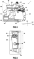
Fig. 5] Figure 5 presents a schematic drawing of a second embodiment of the invention. - [
Fig. 6] Figure 6 presents another view of the second embodiment of the present invention. - [
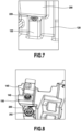
Fig. 7] Figure 7 presents another view of the second embodiment of the present invention. - [
Fig. 8] Figure 8 presents another view of the second embodiment of the present invention. - In all the figures, similar elements are designated by identical numerical references.
- A first example embodiment of the invention will then be described with reference to
figures 1 to 4 . -
Figures 1 to 4 present atank arrangement 1 for a work vehicle according to an example embodiment of the invention. This tank arrangement can for instance be implemented on a work vehicle such as a tractor, or more generally on an agricultural engine. - The
tank arrangement 1 as presented comprises afuel tank 100 and aurea tank 200, that are distinct from each other. - The
fuel tank 100 as presented comprises afuel tank body 110 which presents amain portion 102 and asecondary portion 104. - The
secondary portion 104 comprises an upper portion and anintermediate portion 130 140, that are arranged successively from a top to a bottom along a vertical direction. - The
fuel tank body 110 presents an inner volume adapted to store fuel. The fuel tank body extends along a main direction X-X which is defined as corresponding to a front-rear direction for a work vehicle. A vertical direction is defined as the vertical axis Z-Z, and a width direction Y-Y is defined as perpendicular to both the vertical direction Z-Z and the main direction X-X. A front face of thefuel tank 100 is defined along the width direction, which is designed to be the face of the fuel tank that faces an exterior side of the work vehicle. In the illustrated embodiment, themain portion 102 and thesecondary portion 104 are arranged successively along the main direction X-X. - For instance, when implemented on a tractor, the
tank arrangement 1 is typically arranged in a midway portion of a main body of the tractor, between the engine compartment and the tractor cab, so that the main direction X-X of the fuel tank body corresponds to the front-rear direction of the tractor, the width direction Y-Y corresponds to the transverse direction of the tractor; and the front face of thefuel tank 100 protrudes from a lateral side of the tractor.Thefuel tank body 110 is provided with afuel inlet 142 on its front face or on an upper face, typically on the front face or on an upper face of theupper portion 140, said fuel inlet being adapted to enable to fill thefuel tank 100 with fuel. - The
secondary portion 104 of thefuel tank body 110 is configured so as to define a housing adapted to receive theurea tank 200. The housing is typically defined by theintermediate portion 130. - To define the housing, the
fuel tank body 110 is typically defined such that the intermediate portion presents a recess defining the housing adapted to accommodate theurea tank 200. The housing opens on the front face of thefuel tank 100. The housing is defined such that the urea tank can be inserted below theupper portion 140 along the vertical direction Z-Z, in front of theintermediate portion 130 along the width direction Y-Y, and side-by-side with themain portion 102 of thefuel tank 100 along the main direction X-X. - The
urea tank 200 is adapted to be inserted within the housing defined by thefuel tank 100, typically by sliding along the width direction of thefuel tank 100, from the front face of thefuel tank 100. Theurea tank 200 can therefore be engaged within the housing of thefuel tank 100. In the following description we will refer to an engaged configuration of theurea tank 200 within thefuel tank 100 as a configuration where theurea tank 200 is fully engaged within the housing of thefuel tank 100, i.e. theurea tank 200 abuts against theintermediate portion 130 of thefuel tank 100 along the width direction Y-Y. - The
fuel tank 100 typically comprising guiding means adapted to guide the displacement of theurea tank 200 within the housing provided by thefuel tank 100. - The
urea tank 200 presents a shape that is adapted to be engaged within the housing provided by thefuel tank 100. The shape of theurea tank 200 is typically complementary to the shape of the housing defined by thefuel tank 100. The shape represented in the figures is however only meant to be an example embodiment, and should not be interpreted as limiting the scope of the present invention. - The
urea tank 200 typically presents a urea inlet provided in a top portion of a front face of theurea tank 200. In the illustrated embodiment, theurea inlet 202 is provided on a biased portion between a front face and a top face of the urea tank. Theurea inlet 202 is adapted to enable the filling of theurea tank 200. - The
urea tank 200 is provided withplug assembly 210 which is here provided on the top face of theurea tank 200, thisplug assembly 210 being configured to connect theurea tank 200 to a control unit and to an engine of the work vehicle. - The
upper portion 140 of thefuel tank 100 is typically provided with agroove 144 to accommodate theplug assembly 210 when theurea tank 200 is inserted within the housing of thefuel tank 100, and to accommodate connectors adapted to be connected to theplug assembly 210. Thegroove 144 extends through the width of thefuel tank 100 along the width direction Y-Y so as to define a through hole. Ducts, piles and connectors can then extend through thefuel tank 100 to be connected to theplug assembly 210 of theurea tank 200. Agroove cover 146 can be arranged on an outer lateral side of thegroove 144, so as to protect theplug assembly 210 and the various ducts and pipes arranged within thegroove 144 from outer elements and projections. Thegroove cover 146 as illustrated is formed so as to cover thegroove 144 while being located behind theurea inlet 202. - The
tank arrangement 1 is typically provided with alock 20, adapted to lock theurea tank 200 in position within the housing of thefuel tank 100 when theurea tank 200 is in the engaged configuration. In the illustrated embodiment, thelock 20 is provided on the front face of theurea tank 200 and on the front face of thefuel tank 100. This embodiment is only meant as an example, and one can understand that thelock 20 can be located in any appropriate location that can be easily reached by an operator, and that thetank arrangement 1 can be provided with one or more ofsuch locks 20 that can be identical or distinct. In the illustrated embodiment, thelock 20 comprises tabs that are assembled to both thefuel tank 100 and theurea tank 200 with engaging means such as screws. - The
urea tank 200 is provided with adrain 220, arranged on a bottom side of theurea tank 200. Thedrain 220 is adapted to enable an operator to empty the contents of theurea tank 200. - The
drain 220 is typically arranged proximal to the front face of theurea tank 200, so as to be easily reachable by an operator. According to an example embodiment, thedrain 220 is located within 20 cm of the front face of theurea tank 200, or typically within 10 cm of the front face of theurea tank 200. - In the embodiment disclosed in
figures 1 to 4 , atank support 300 is provided under thetank arrangement 1 along the vertical direction Z-Z. - The
tank arrangement 1 is therefore supported by thetank support 300. - The
tank support 300 is provided with a notch 322 formed so that theurea drain 220 is in front of the notch 322 when the urea tank is in the engaged configuration within the housing defined by the fuel tank 100.The notch 322 extends through the whole thickness of thetank support 300 along the vertical direction Z-Z, such that when urea flows from thedrain 220, urea can flow through thefuel tank 100 without coming in contact withtank support 300. In other words, urea can be directly discharged from thedrain 220 of theurea tank 200 to the ground or to a receptacle without flowing on thetank support 300. Such a configuration enables to increase the flow and therefore speed up the draining operation of theurea tank 200 while theurea tank 200 remains engaged within the housing of thefuel tank 100. - In the illustrated embodiment, the
tank support 300 compriseslateral abutments 310, adapted to form an abutment along the rear-front direction X-X. Theabutments 310 are adapted to prevent thetank arrangement 1 to move forward along the rear-front direction X-X for instance in case of a sudden stop of a work vehicle. Similar abutments can also be provided to prevent a backward displacement along the rear-front direction X-X in case of sudden acceleration. In other words, thetank support 300 can comprise abutments adapted to prevent the displacement of thetank arrangement 1 along the main direction X-X, i.e. the front-rear direction X-X. - In an embodiment, the
upper portion 140 of thefuel tank 100 presents arecess 145 adapted to house a toolbox. Thisrecess 145 is configured so that a toolbox can be fit within, while a top portion of the toolbox will not protrude from theupper portion 140 of thefuel tank 100 along the vertical direction Z-Z. - Such a configuration enables to house a toolbox while preventing a potential interference with implements of the work vehicle such as a front loader. In addition, the position of the toolbox is lowered, which enables to increase the visibility for the driver.
- Further, the toolbox can be maintained in position by the shape of the
recess 145, and can be directly opened by an operator without having to remove it from therecess 145, which facilitated the use of the toolbox. - A second embodiment is then described with reference to
figures 5 to 8 . Only the distinguishing features between the two embodiments will be detailed hereafter. - In this embodiment, the
secondary portion 104 of thefuel tank 100 comprises abase portion 120 formed under theintermediate portion 130 along the vertical direction Z-Z. - In this embodiment, the housing to accommodate the
urea tank 200 is therefore defined between thebase portion 120 and theupper portion 140 along the vertical direction Z-Z. Thebase portion 120 is arranged on and supported by thetank support 300. - In this embodiment, the
base portion 120 of thefuel tank 100 is provided with anotch 122 adapted to be in line with thedrain 220 and with the notch 322 formed in thetank support 300 when theurea tank 200 is engaged within the housing of thefuel tank 100. - The
notch 122 extends through the whole thickness of thebase portion 120 of thefuel tank 100 along the vertical direction Z-Z, such that when urea flows from thedrain 220, urea can flow through thefuel tank 100 without coming in contact with thefuel tank 100, or more precisely in contact with thebase portion 120 of thefuel tank 100, nor with thetank support 300. In other words, urea can be directly discharged from thedrain 220 of theurea tank 200 to the ground or to a receptacle without flowing on thefuel tank 100 or on thetank support 300. Such a configuration enables to increase the flow and therefore speed up the draining operation of theurea tank 200 while theurea tank 200 remains engaged within the housing of thefuel tank 100. - In the embodiment disclosed, the
intermediate portion 130 of thefuel tank 100 defines twoshoulder portions 132 arranged at two different heights. Theurea tank 200 comprises two corresponding steppedportions 232, adapted to fit under theshoulder portions 130 of thefuel tank 100 when theurea tank 200 is engaged in the housing. This configuration ensures a proper maintain of theurea tank 200 and prevents it from tilting towards the opening of the housing. - The embodiments disclosed enable to provide an
improved tank arrangement 1 which ensure a proper holding of theurea tank 200 while maximizing the volume of thefuel tank 100. In addition, the various inlets and outlets of theurea tank 200 can be easily reached so as to ensure a proper connection of the urea tank, and allow an easy filling and draining of theurea tank 200. - Although the present invention has been described with reference to specific exemplary embodiments, it is obvious that modifications and changes can be carried out on these examples with departing from the general scope of the invention as defined by the claims. In particular, individual features of the different embodiments illustrated/mentioned can be combined into additional embodiments. Consequently, the description and the drawings must be considered in an illustrative, rather than a restrictive sense.
- It is also obvious that all the features described with reference to a method are transposable, alone or in combination, to a device, and conversely, all the features described with reference to a device are transposable, alone or in combination, to a method.
Claims (15)
- A tank arrangement (1) comprising a fuel tank (100) and a urea tank (200),wherein the tank arrangement presents a front-rear direction (X-X), a transverse direction (Y-Y) and a vertical direction (Z-Z),the fuel tank (100) comprises a fuel tank body (110), the tank body (110) comprising a main portion (102) and a secondary portion (104),wherein the secondary portion (104) comprises an upper portion (140) and an intermediate portion (130) arranged successively along the vertical direction (Z-Z), configured so as to define a housing to accommodate the urea tank (200),the urea tank (200) can be inserted into an engaged configuration within said housing from a front face of the fuel tank (100) along the transverse direction (Y-Y),wherein in the engaged configuration, the urea tank (200) is arranged- under the upper portion (140) of the secondary portion (104) along the vertical direction (Z-Z),- in abutment on the intermediate portion (130) along the transverse direction (Y-Y),- in abutment on the primary portion (102) along the front-rear direction (X-X)the urea tank (200) comprises a urea drain (220) on a lower portion of the urea tank (200) along the vertical direction (Z-Z),the secondary portion (104) of the fuel tank (100) comprises a groove (144) that extends through the fuel tank (100) along the transverse direction (Y-Y), adapted to allow ducts to go through the secondary portion (104) of the fuel tank (100) along the transverse direction (Y-Y) to be connected to the urea tank (200).
- The tank arrangement (1) of claim 1, wherein the urea tank (200) comprises a urea drain (220) on a lower portion of the urea tank (200) along the vertical direction (Z-Z), the tank arrangement (1) being configured such that so that fluid flowing from the urea drain (220) can be discharged along the vertical direction (Z-Z) without flowing on the tank arrangement (1).
- The tank arrangement (1) of claim 1 or claim 2, which further comprises a tank support (300) arranged below the fuel tank (100) and the urea tank (200) along the vertical direction (Z-Z), wherein the tank support (300) is provided with a notch (322), such that the urea drain (220) is in front of said notch (322) when the urea tank (200) is in the engaged configuration within the fuel tank (100).
- The tank arrangement (1) of claim 3, wherein the notch (322) extends from a front face of the tank support (300) of the fuel tank (100).
- The tank arrangement (1) of claim 3 or claim 4, wherein the notch (322) and the urea drain (220) are arranged so that fluid flowing from the urea drain (220) can be discharged without flowing on the tank support (300).
- The tank arrangement (1) of any one of claims 3 to 5, wherein thesecondary portion (104) of the fuel tank comprises a base portion (120), formed such that in the engaged configuration, the urea tank (200) is arranged between the base portion (120) and the upper portion (140) along the vertical direction (Z-Z),wherein the base portion (120) of the fuel tank (100) is provided with a notch (122), such that the urea drain (220) is in front of said notch (122) when the urea tank (200) is in the engaged configuration within the fuel tank (100).
- The tank arrangement (1) of claim 6, wherein the notch (122) extends from a front face of the base portion (120) of the fuel tank (100), and extends through the base portion (120) along the vertical direction (Z-Z).
- The tank arrangement (1) of claim 6 or claim 7, wherein the notch (122) and the urea drain (220) are arranged so that fluid flowing from the urea drain (220) can be discharged without flowing on the base portion (120) of the fuel tank (100).
- The tank arrangement (1) of any one of claims 6 to 8, wherein the tank support (300) comprises lateral abutments (310) , adapted to form an abutment along the rear-front direction (X-X).
- The tank arrangement (1) of any one of claims 1 to 9, wherein the urea tank (200) comprises a urea inlet (202) on an upper face of the urea tank (200), said urea inlet (202) being configured to be connected to ducts and/or lines through the through hole formed on the secondary portion (104) of the fuel tank (100).
- The tank arrangement (1) of any one of claims 1 to 10, wherein the upper portion (140) of the fuel tank (100) presents a recess (145) adapted to house a toolbox.
- The tank arrangement (1) of claim 11, wherein the recess (145) is configured so that a toolbox inserted in the recess does not protrude over the upper portion (140) of the fuel tank (100) along the vertical direction (Z-Z).
- The tank arrangement (1) of any one of claims 1 to 12, which further comprises a lock (20) adapted to immobilize the urea tank (200) in the engaged configuration within the housing of the fuel tank (100).
- The tank arrangement (1) of any one of claims 1 to 13, wherein the intermediate portion (130) of the fuel tank (100) presents a shoulder portion (132) and the urea tank (200) presents a stepped portion (232) adapted to fit under the shoulder portion (132) in the engaged configuration.
- The tank arrangement (1) of any one of claims 1 to 14, wherein the fuel tank (100) and the urea tank (200) comprise guiding means adapted to guide the insertion of the urea tank (200) within the housing defined by the fuel tank (100).
Applications Claiming Priority (1)
| Application Number | Priority Date | Filing Date | Title |
|---|---|---|---|
| EP23305167 | 2023-02-08 |
Publications (2)
| Publication Number | Publication Date |
|---|---|
| EP4414199A1 true EP4414199A1 (en) | 2024-08-14 |
| EP4414199B1 EP4414199B1 (en) | 2025-10-29 |
Family
ID=85328969
Family Applications (1)
| Application Number | Title | Priority Date | Filing Date |
|---|---|---|---|
| EP23306307.2A Active EP4414199B1 (en) | 2023-02-08 | 2023-07-28 | Improved tank for a work vehicle |
Country Status (3)
| Country | Link |
|---|---|
| US (1) | US12434552B2 (en) |
| EP (1) | EP4414199B1 (en) |
| JP (1) | JP2024112753A (en) |
Citations (4)
| Publication number | Priority date | Publication date | Assignee | Title |
|---|---|---|---|---|
| EP2017113A1 (en) * | 2007-06-06 | 2009-01-21 | Iveco S.p.A. | Method and system for fitting one or more additional tanks to a tank of an industrial or commercial vehicle |
| WO2009131561A1 (en) * | 2008-04-21 | 2009-10-29 | Mack Trucks, Inc. | Apparatus for separately containing different fluids |
| US20180038075A1 (en) * | 2015-06-03 | 2018-02-08 | Hitachi Construction Machinery Co., Ltd. | Construction Machine |
| CN106314132B (en) * | 2016-09-22 | 2019-06-14 | 中联重机股份有限公司 | A kind of motor vehicle multifunctional fuel tank |
Family Cites Families (5)
| Publication number | Priority date | Publication date | Assignee | Title |
|---|---|---|---|---|
| JP2011063988A (en) * | 2009-09-17 | 2011-03-31 | Kobelco Contstruction Machinery Ltd | Construction machine |
| JP6218674B2 (en) * | 2014-05-28 | 2017-10-25 | 株式会社クボタ | Work vehicle |
| JP6815255B2 (en) * | 2017-03-30 | 2021-01-20 | ヤンマーパワーテクノロジー株式会社 | Tractor |
| US11660955B2 (en) * | 2019-03-18 | 2023-05-30 | Kubota Corporation | Fuel tank of work vehicle and work vehicle |
| CN214063182U (en) * | 2020-12-07 | 2021-08-27 | 宁波春华汽配有限公司 | Fuel oil and urea tank module |
-
2023
- 2023-07-28 US US18/227,330 patent/US12434552B2/en active Active
- 2023-07-28 JP JP2023123730A patent/JP2024112753A/en active Pending
- 2023-07-28 EP EP23306307.2A patent/EP4414199B1/en active Active
Patent Citations (4)
| Publication number | Priority date | Publication date | Assignee | Title |
|---|---|---|---|---|
| EP2017113A1 (en) * | 2007-06-06 | 2009-01-21 | Iveco S.p.A. | Method and system for fitting one or more additional tanks to a tank of an industrial or commercial vehicle |
| WO2009131561A1 (en) * | 2008-04-21 | 2009-10-29 | Mack Trucks, Inc. | Apparatus for separately containing different fluids |
| US20180038075A1 (en) * | 2015-06-03 | 2018-02-08 | Hitachi Construction Machinery Co., Ltd. | Construction Machine |
| CN106314132B (en) * | 2016-09-22 | 2019-06-14 | 中联重机股份有限公司 | A kind of motor vehicle multifunctional fuel tank |
Also Published As
| Publication number | Publication date |
|---|---|
| JP2024112753A (en) | 2024-08-21 |
| US12434552B2 (en) | 2025-10-07 |
| US20240262188A1 (en) | 2024-08-08 |
| EP4414199B1 (en) | 2025-10-29 |
Similar Documents
| Publication | Publication Date | Title |
|---|---|---|
| EP2876219B1 (en) | Construction machine | |
| EP3305993B1 (en) | Construction machine | |
| US20070163660A1 (en) | Fuel tank for an agricultural vehicle | |
| EP4253117A1 (en) | Fuel tank of working vehicle | |
| US12434552B2 (en) | Tank for a work vehicle | |
| EP3708431B1 (en) | Vehicle console | |
| EP4685036A1 (en) | Agricultural tractor | |
| EP2234834B1 (en) | Fuel tank system | |
| JP2002266377A (en) | Fuel supply device for construction machinery | |
| US10953743B2 (en) | Saddle tank with swash barrier | |
| EP0832777A1 (en) | Inlet pipe structure | |
| DE102005032497B4 (en) | Cover of a gas tank | |
| US12280657B2 (en) | Pressure relief assembly and a valve assembly that uses the pressure relief assembly | |
| CN105637151B (en) | Hydraulic excavator | |
| CN210344236U (en) | Transmission case cover body assembly capable of being matched | |
| US11598301B2 (en) | Fastener assembly | |
| WO2024143217A1 (en) | Electric work vehicle | |
| US11506159B1 (en) | Dual fuel tank system with internally mounted fuel tanks in line with actuators | |
| EP3736157B1 (en) | Fuel tank of work vehicle and work vehicle | |
| US20230415566A1 (en) | Device for filling a fuel tank with fuel | |
| EP4421242B1 (en) | Working vehicle | |
| JPH0628303U (en) | Hydraulic oil tank | |
| JPH11245676A (en) | Fuel tank device for construction machine | |
| JPH0131579Y2 (en) | ||
| JP2009002400A (en) | Work vehicle |
Legal Events
| Date | Code | Title | Description |
|---|---|---|---|
| PUAI | Public reference made under article 153(3) epc to a published international application that has entered the european phase |
Free format text: ORIGINAL CODE: 0009012 |
|
| STAA | Information on the status of an ep patent application or granted ep patent |
Free format text: STATUS: REQUEST FOR EXAMINATION WAS MADE |
|
| 17P | Request for examination filed |
Effective date: 20230728 |
|
| AK | Designated contracting states |
Kind code of ref document: A1 Designated state(s): AL AT BE BG CH CY CZ DE DK EE ES FI FR GB GR HR HU IE IS IT LI LT LU LV MC ME MK MT NL NO PL PT RO RS SE SI SK SM TR |
|
| GRAP | Despatch of communication of intention to grant a patent |
Free format text: ORIGINAL CODE: EPIDOSNIGR1 |
|
| STAA | Information on the status of an ep patent application or granted ep patent |
Free format text: STATUS: GRANT OF PATENT IS INTENDED |
|
| INTG | Intention to grant announced |
Effective date: 20250818 |
|
| GRAS | Grant fee paid |
Free format text: ORIGINAL CODE: EPIDOSNIGR3 |
|
| GRAA | (expected) grant |
Free format text: ORIGINAL CODE: 0009210 |
|
| STAA | Information on the status of an ep patent application or granted ep patent |
Free format text: STATUS: THE PATENT HAS BEEN GRANTED |
|
| AK | Designated contracting states |
Kind code of ref document: B1 Designated state(s): AL AT BE BG CH CY CZ DE DK EE ES FI FR GB GR HR HU IE IS IT LI LT LU LV MC ME MK MT NL NO PL PT RO RS SE SI SK SM TR |
|
| REG | Reference to a national code |
Ref country code: CH Ref legal event code: F10 Free format text: ST27 STATUS EVENT CODE: U-0-0-F10-F00 (AS PROVIDED BY THE NATIONAL OFFICE) Effective date: 20251029 Ref country code: GB Ref legal event code: FG4D |
|
| REG | Reference to a national code |
Ref country code: IE Ref legal event code: FG4D |
|
| REG | Reference to a national code |
Ref country code: DE Ref legal event code: R096 Ref document number: 602023008038 Country of ref document: DE |
|
| REG | Reference to a national code |
Ref country code: NL Ref legal event code: MP Effective date: 20251029 |
|
| PG25 | Lapsed in a contracting state [announced via postgrant information from national office to epo] |
Ref country code: ES Free format text: LAPSE BECAUSE OF FAILURE TO SUBMIT A TRANSLATION OF THE DESCRIPTION OR TO PAY THE FEE WITHIN THE PRESCRIBED TIME-LIMIT Effective date: 20251029 |
|
| REG | Reference to a national code |
Ref country code: LT Ref legal event code: MG9D |
|
| PG25 | Lapsed in a contracting state [announced via postgrant information from national office to epo] |
Ref country code: NO Free format text: LAPSE BECAUSE OF FAILURE TO SUBMIT A TRANSLATION OF THE DESCRIPTION OR TO PAY THE FEE WITHIN THE PRESCRIBED TIME-LIMIT Effective date: 20260129 |
|
| PG25 | Lapsed in a contracting state [announced via postgrant information from national office to epo] |
Ref country code: FI Free format text: LAPSE BECAUSE OF FAILURE TO SUBMIT A TRANSLATION OF THE DESCRIPTION OR TO PAY THE FEE WITHIN THE PRESCRIBED TIME-LIMIT Effective date: 20251029 Ref country code: AT Free format text: LAPSE BECAUSE OF FAILURE TO SUBMIT A TRANSLATION OF THE DESCRIPTION OR TO PAY THE FEE WITHIN THE PRESCRIBED TIME-LIMIT Effective date: 20251029 Ref country code: HR Free format text: LAPSE BECAUSE OF FAILURE TO SUBMIT A TRANSLATION OF THE DESCRIPTION OR TO PAY THE FEE WITHIN THE PRESCRIBED TIME-LIMIT Effective date: 20251029 |
|
| REG | Reference to a national code |
Ref country code: AT Ref legal event code: MK05 Ref document number: 1851196 Country of ref document: AT Kind code of ref document: T Effective date: 20251029 |
|
| PG25 | Lapsed in a contracting state [announced via postgrant information from national office to epo] |
Ref country code: NL Free format text: LAPSE BECAUSE OF FAILURE TO SUBMIT A TRANSLATION OF THE DESCRIPTION OR TO PAY THE FEE WITHIN THE PRESCRIBED TIME-LIMIT Effective date: 20251029 |
|
| PG25 | Lapsed in a contracting state [announced via postgrant information from national office to epo] |
Ref country code: RS Free format text: LAPSE BECAUSE OF FAILURE TO SUBMIT A TRANSLATION OF THE DESCRIPTION OR TO PAY THE FEE WITHIN THE PRESCRIBED TIME-LIMIT Effective date: 20260129 |
|
| PG25 | Lapsed in a contracting state [announced via postgrant information from national office to epo] |
Ref country code: IS Free format text: LAPSE BECAUSE OF FAILURE TO SUBMIT A TRANSLATION OF THE DESCRIPTION OR TO PAY THE FEE WITHIN THE PRESCRIBED TIME-LIMIT Effective date: 20260228 |
|
| PG25 | Lapsed in a contracting state [announced via postgrant information from national office to epo] |
Ref country code: PT Free format text: LAPSE BECAUSE OF FAILURE TO SUBMIT A TRANSLATION OF THE DESCRIPTION OR TO PAY THE FEE WITHIN THE PRESCRIBED TIME-LIMIT Effective date: 20260302 |
|
| PG25 | Lapsed in a contracting state [announced via postgrant information from national office to epo] |
Ref country code: PL Free format text: LAPSE BECAUSE OF FAILURE TO SUBMIT A TRANSLATION OF THE DESCRIPTION OR TO PAY THE FEE WITHIN THE PRESCRIBED TIME-LIMIT Effective date: 20251029 |
|
| PG25 | Lapsed in a contracting state [announced via postgrant information from national office to epo] |
Ref country code: LV Free format text: LAPSE BECAUSE OF FAILURE TO SUBMIT A TRANSLATION OF THE DESCRIPTION OR TO PAY THE FEE WITHIN THE PRESCRIBED TIME-LIMIT Effective date: 20251029 |
|
| PG25 | Lapsed in a contracting state [announced via postgrant information from national office to epo] |
Ref country code: BG Free format text: LAPSE BECAUSE OF FAILURE TO SUBMIT A TRANSLATION OF THE DESCRIPTION OR TO PAY THE FEE WITHIN THE PRESCRIBED TIME-LIMIT Effective date: 20251029 |