EP4414194A1 - Compressed air driven evaporative cooling system - Google Patents
Compressed air driven evaporative cooling system Download PDFInfo
- Publication number
- EP4414194A1 EP4414194A1 EP23155246.4A EP23155246A EP4414194A1 EP 4414194 A1 EP4414194 A1 EP 4414194A1 EP 23155246 A EP23155246 A EP 23155246A EP 4414194 A1 EP4414194 A1 EP 4414194A1
- Authority
- EP
- European Patent Office
- Prior art keywords
- storage container
- valve
- fuel cell
- water spray
- water
- Prior art date
- Legal status (The legal status is an assumption and is not a legal conclusion. Google has not performed a legal analysis and makes no representation as to the accuracy of the status listed.)
- Pending
Links
- 238000001816 cooling Methods 0.000 title claims abstract description 65
- XLYOFNOQVPJJNP-UHFFFAOYSA-N water Substances O XLYOFNOQVPJJNP-UHFFFAOYSA-N 0.000 claims abstract description 122
- 239000000446 fuel Substances 0.000 claims abstract description 76
- 239000007921 spray Substances 0.000 claims abstract description 74
- 238000010586 diagram Methods 0.000 description 6
- 239000000498 cooling water Substances 0.000 description 4
- 230000005611 electricity Effects 0.000 description 4
- UFHFLCQGNIYNRP-UHFFFAOYSA-N Hydrogen Chemical compound [H][H] UFHFLCQGNIYNRP-UHFFFAOYSA-N 0.000 description 2
- QVGXLLKOCUKJST-UHFFFAOYSA-N atomic oxygen Chemical compound [O] QVGXLLKOCUKJST-UHFFFAOYSA-N 0.000 description 2
- 239000012530 fluid Substances 0.000 description 2
- 239000001257 hydrogen Substances 0.000 description 2
- 229910052739 hydrogen Inorganic materials 0.000 description 2
- 239000001301 oxygen Substances 0.000 description 2
- 229910052760 oxygen Inorganic materials 0.000 description 2
- 239000000126 substance Substances 0.000 description 2
- 239000000725 suspension Substances 0.000 description 2
- 238000004378 air conditioning Methods 0.000 description 1
- 238000002485 combustion reaction Methods 0.000 description 1
- 238000010276 construction Methods 0.000 description 1
- 239000002826 coolant Substances 0.000 description 1
- 238000003487 electrochemical reaction Methods 0.000 description 1
- 238000007710 freezing Methods 0.000 description 1
- 230000008014 freezing Effects 0.000 description 1
- 239000000463 material Substances 0.000 description 1
- 238000012986 modification Methods 0.000 description 1
- 230000004048 modification Effects 0.000 description 1
- 239000002699 waste material Substances 0.000 description 1
Images


Classifications
-
- B—PERFORMING OPERATIONS; TRANSPORTING
- B60—VEHICLES IN GENERAL
- B60K—ARRANGEMENT OR MOUNTING OF PROPULSION UNITS OR OF TRANSMISSIONS IN VEHICLES; ARRANGEMENT OR MOUNTING OF PLURAL DIVERSE PRIME-MOVERS IN VEHICLES; AUXILIARY DRIVES FOR VEHICLES; INSTRUMENTATION OR DASHBOARDS FOR VEHICLES; ARRANGEMENTS IN CONNECTION WITH COOLING, AIR INTAKE, GAS EXHAUST OR FUEL SUPPLY OF PROPULSION UNITS IN VEHICLES
- B60K1/00—Arrangement or mounting of electrical propulsion units
-
- H—ELECTRICITY
- H01—ELECTRIC ELEMENTS
- H01M—PROCESSES OR MEANS, e.g. BATTERIES, FOR THE DIRECT CONVERSION OF CHEMICAL ENERGY INTO ELECTRICAL ENERGY
- H01M8/00—Fuel cells; Manufacture thereof
- H01M8/04—Auxiliary arrangements, e.g. for control of pressure or for circulation of fluids
- H01M8/04007—Auxiliary arrangements, e.g. for control of pressure or for circulation of fluids related to heat exchange
- H01M8/04029—Heat exchange using liquids
-
- B—PERFORMING OPERATIONS; TRANSPORTING
- B60—VEHICLES IN GENERAL
- B60K—ARRANGEMENT OR MOUNTING OF PROPULSION UNITS OR OF TRANSMISSIONS IN VEHICLES; ARRANGEMENT OR MOUNTING OF PLURAL DIVERSE PRIME-MOVERS IN VEHICLES; AUXILIARY DRIVES FOR VEHICLES; INSTRUMENTATION OR DASHBOARDS FOR VEHICLES; ARRANGEMENTS IN CONNECTION WITH COOLING, AIR INTAKE, GAS EXHAUST OR FUEL SUPPLY OF PROPULSION UNITS IN VEHICLES
- B60K11/00—Arrangement in connection with cooling of propulsion units
- B60K11/02—Arrangement in connection with cooling of propulsion units with liquid cooling
-
- B—PERFORMING OPERATIONS; TRANSPORTING
- B60—VEHICLES IN GENERAL
- B60K—ARRANGEMENT OR MOUNTING OF PROPULSION UNITS OR OF TRANSMISSIONS IN VEHICLES; ARRANGEMENT OR MOUNTING OF PLURAL DIVERSE PRIME-MOVERS IN VEHICLES; AUXILIARY DRIVES FOR VEHICLES; INSTRUMENTATION OR DASHBOARDS FOR VEHICLES; ARRANGEMENTS IN CONNECTION WITH COOLING, AIR INTAKE, GAS EXHAUST OR FUEL SUPPLY OF PROPULSION UNITS IN VEHICLES
- B60K1/00—Arrangement or mounting of electrical propulsion units
- B60K2001/003—Arrangement or mounting of electrical propulsion units with means for cooling the electrical propulsion units
- B60K2001/005—Arrangement or mounting of electrical propulsion units with means for cooling the electrical propulsion units the electric storage means
-
- B—PERFORMING OPERATIONS; TRANSPORTING
- B60—VEHICLES IN GENERAL
- B60K—ARRANGEMENT OR MOUNTING OF PROPULSION UNITS OR OF TRANSMISSIONS IN VEHICLES; ARRANGEMENT OR MOUNTING OF PLURAL DIVERSE PRIME-MOVERS IN VEHICLES; AUXILIARY DRIVES FOR VEHICLES; INSTRUMENTATION OR DASHBOARDS FOR VEHICLES; ARRANGEMENTS IN CONNECTION WITH COOLING, AIR INTAKE, GAS EXHAUST OR FUEL SUPPLY OF PROPULSION UNITS IN VEHICLES
- B60K1/00—Arrangement or mounting of electrical propulsion units
- B60K2001/003—Arrangement or mounting of electrical propulsion units with means for cooling the electrical propulsion units
- B60K2001/006—Arrangement or mounting of electrical propulsion units with means for cooling the electrical propulsion units the electric motors
-
- B—PERFORMING OPERATIONS; TRANSPORTING
- B60—VEHICLES IN GENERAL
- B60Y—INDEXING SCHEME RELATING TO ASPECTS CROSS-CUTTING VEHICLE TECHNOLOGY
- B60Y2400/00—Special features of vehicle units
- B60Y2400/20—Energy converters
- B60Y2400/202—Fuel cells
-
- H—ELECTRICITY
- H01—ELECTRIC ELEMENTS
- H01M—PROCESSES OR MEANS, e.g. BATTERIES, FOR THE DIRECT CONVERSION OF CHEMICAL ENERGY INTO ELECTRICAL ENERGY
- H01M2250/00—Fuel cells for particular applications; Specific features of fuel cell system
- H01M2250/20—Fuel cells in motive systems, e.g. vehicle, ship, plane
-
- Y—GENERAL TAGGING OF NEW TECHNOLOGICAL DEVELOPMENTS; GENERAL TAGGING OF CROSS-SECTIONAL TECHNOLOGIES SPANNING OVER SEVERAL SECTIONS OF THE IPC; TECHNICAL SUBJECTS COVERED BY FORMER USPC CROSS-REFERENCE ART COLLECTIONS [XRACs] AND DIGESTS
- Y02—TECHNOLOGIES OR APPLICATIONS FOR MITIGATION OR ADAPTATION AGAINST CLIMATE CHANGE
- Y02E—REDUCTION OF GREENHOUSE GAS [GHG] EMISSIONS, RELATED TO ENERGY GENERATION, TRANSMISSION OR DISTRIBUTION
- Y02E60/00—Enabling technologies; Technologies with a potential or indirect contribution to GHG emissions mitigation
- Y02E60/30—Hydrogen technology
- Y02E60/50—Fuel cells
Definitions
- the disclosure relates generally to a compressed air driven evaporative cooling system.
- the disclosure relates to a water spray cooling system for fuel cell electric vehicles.
- the disclosure can be applied in any fuel cell electric vehicles, such as cars, heavy-duty trucks, buses, construction equipment, marine vessels etc. Although the disclosure will be described with respect to a particular vehicle, the disclosure is not restricted to any particular vehicles.
- a fuel cell is a device that can produce electricity by converting chemical energy from a fuel into electrical energy through an electrochemical reaction within a fuel cell stack, instead of converting the chemical energy from the fuel into heat through combustion.
- Fuel cells can produce electricity continuously as long as fuel and oxygen are supplied. Fuel cells may provide power for small electric/electronic products, industries, households, and vehicles.
- a fuel cell electric vehicle (FCEV) is an electric vehicle that uses a fuel cell, sometimes in combination with a small battery or supercapacitor, to power its onboard electric motor. Fuel cells in vehicles generate electricity generally using oxygen from the air and compressed hydrogen.
- FCEVs Cooling of FCEVs is a huge challenge, usually an upsized cooling system with an extreme power fan is needed.
- a fan with extreme power creates noise and uses up some of the electricity generated by the fuel cell (FC) leaving less for propulsion and increasing cost.
- FC fuel cell
- the FC needs a special deionized coolant and bigger radiators need to be manufactured in a special material adding further cost to the cooling system.
- the present disclosure provides a cooling system with reduced cost and size compared to the prior art solutions.
- a water spray cooling system for a fuel cell electric vehicle comprises a first storage container configured to store exhaust water generated from a fuel cell system comprised in the fuel cell electric vehicle and a second storage container connected to the first storage container via a first valve.
- the cooling system further comprises a first tube connecting a first opening of the second storage container with an air tank via a second valve.
- the air tank comprises compressed air generated from a compressed air system comprised in the fuel cell electric vehicle.
- the cooling system further comprises one or more water spray nozzles connected to a second opening of the second storage container through a second tube.
- the first and second valves are configured to be controlled during a water spray event such that the first valve is first open to fill water from the first storage container to the second storage container and then closed, and after the first valve is closed, the second valve is open to deliver the compressed air from the air tank to the second storage container to create a water spray at the water spray nozzle.
- the water spray may be supplied to a radiator of the fuel cell system comprised in the fuel cell electric vehicle.
- the second storage container may be smaller than the first storage container and have a water volume needed for one water spray event.
- the first and second storage containers are integrated as a two-chamber tank.
- a first chamber is the first storage container
- a second chamber is the second storage container
- the first valve is a check valve and arranged between the two chambers.
- the sizes of the second storage container, the second tube and the water spray nozzle, as well as the open time of the second valve are configured such that the compressed air presses out all water in the second storage container, the second tube and the water spray nozzle during one water spray event.
- a fuel cell electric vehicle comprising the cooling system described above is provided.
- a cooling method for a fuel cell electric vehicle comprises providing a first storage container configured to store exhaust water generated from a fuel cell system comprised in the fuel cell electric vehicle; providing a second storage container connected to the first storage container via a first valve; providing a first tube connecting a first opening of the second storage container with an air tank via a second valve, wherein the air tank comprises compressed air generated from a compressed air system comprised in the fuel cell electric vehicle; providing one or more water spray nozzles connected to a second opening of the second storage container through a second tube; and controlling the first and second valves during a water spray event such that the first valve is first open to fill water from the first storage container to the second storage container and then closed, and after the first valve is closed, the second valve is open to deliver the compressed air from the air tank to the second storage container to create a water spray at the water spray nozzle.
- the cooling method may further comprise controlling a third valve comprised in the second container to be open to the atmosphere during filling water from the first container to the second container.
- the cooling system of the present disclosure uses the compressed air generated from the existing compressed air system comprised in the fuel cell electric vehicle to drive the water spray generation.
- the cooling water is the condensates generated from the fuel cell system.
- the exhaust tank could be pressurized with the compressed air if it was equipped with check valves.
- FCEVs Evaporative cooling is used in large scale in heat exchange facilities and has been proposed to be used also for cooling FCEVs. For example, for each kg of used hydrogen in the FC, 9 kg of water is produced so the FCEV produces its own cooling water. The FCEV exhaust is comparatively cold, so the exhaust cannot carry all of the water in gaseous form. The pressure to drive the water spray in different cooling applications is usually not very high, often in the range of 8-16 bar.
- FCEVs e.g. vehicles with FCs, have a compressed air system or an air compressor so there are already 8-16 bar air pressure available on the vehicles.
- the primary function of the existing compressed air system in the vehicle is to supply compressed air for the vehicle air suspension and braking system.
- the proposal in the present disclosure is to use the compressed air available on the fuel cell electric vehicle to drive the water spray generation.
- the exhaust tank could be pressurized with the compressed air if it was equipped with check valves.
- Fig. 1 is a schematic block diagram showing an example of a water spray cooling system 100 for a fuel cell electric vehicle.
- the cooling system 100 comprises a first storage container 101 configured to store exhaust water generated from a fuel cell system 120 comprised in the fuel cell electric vehicle.
- the cooling system 100 further comprises a second storage container 102 connected to the first storage container 101 via a first valve 103.
- the cooling system 100 further comprises a first tube 104 connecting a first opening 112 of the second storage container 102 with an air tank 130 via a second valve 105.
- the air tank 130 comprises compressed air generated from a compressed air system comprised in the fuel cell electric vehicle.
- the cooling system 100 further comprises one or more water spray nozzles 106 connected to a second opening 113 of the second storage container 102 through a second tube 107.
- the first and second valves 103, 105 are configured to be controlled during a water spray event.
- a water spray event may be defined as an event for generating a water spray from a received command to generate a water spray until the water spray is generated at the water spray nozzle 106.
- the first and second valves 103, 105 are configured to be controlled during a water spray event such that first valve 103 is open to fill water from the first storage container 101 to the second storage container 102 and then closed, and after the first valve 103 is closed, the second valve 105 is open to deliver the compressed air from the air tank 130 to the second storage container 102 to create a water spray at the water spray nozzle 106.
- the water spray may be supplied to a radiator 140 of the fuel cell system comprised in the fuel cell electric vehicle.
- the water spray may also be supplied to other circuits or equipment for lowing their temperature e.g. air conditioning, electric motors and power electronics etc. comprised in the fuel cell electric vehicle.
- the second storage container 102 is smaller than the first storage container 101 and has a water volume needed for generating one water spray event.
- the sizes of the second storage container 102, the second tube 107 and the water spray nozzle 106, as well as the open time of the second valve 105 are configured such that the compressed air presses out substantially all water in the second storage container 102, the second tube 107 and the water spray nozzle 106 during one water spray event.
- the first valve 103 may be a check valve which does not need separate control.
- the check valve also called a one-way valve, is a device that allows the flow of fluids to move only in one direction. That is the first valve 103 allows the water flows from the first storage container 101 to the second storage container 102 and prevents the backflow from the second storage container 102 to the first storage container 101 when the second storage container 102 is pressurized.
- the first valve 103 may also be any type of a control valve.
- the first valve 103 can be controlled to be open to fill the water from the first storage container 101 to the second storage container 102 and to be closed when the second storage container 102 is pressurized.
- the second valve 105 may be any type of a control valve. The timing of opening or closing of the second valve 105 is important. The second valve 105 should be open long enough to blow out the water in the second container 102, in the second tube 107 and even more important the water in the water spray nozzle 106 to avoid potential freezing. If the second valve 105 is open for too long time, it will waste the compressed air which cost energy to compress. Typically, the second valve 105 may be closed before all water in the second container 102 is ejected. When most of the water has been pressed out from the second container 102, it is filled with high pressure air which is sufficient to blow out the water in the second tube 107 and nozzle 106.
- the second container 102 is pressurized with 8 bar air during a first half of the water spray event, the second container 102 is half filled with 8 bar air. Then the second valve 105 is closed, the air in the second container 102 continues to press the water out of the second container 102. When all water has been pressed out from the second container 102, the 8 bar air may have been dropped to 4 bar. So there are still a lot of air pressure left to drain the water in the second tube 107 and nozzle 106.
- the second valve 105 may be controlled automatically by a signal from a controller.
- the opening or closing of the second valve 105 may be done by electrical, hydraulic or pneumatic actuators.
- Air-actuated valves are commonly used because of their simplicity, as they only require a compressed air supply, whereas electrically operated valves require additional cabling and switch gear, and hydraulically actuated valves required high pressure supply and return lines for the hydraulic fluid.
- a third valve 108 may be implemented in the second container 102 opening to the atmosphere to get rid of a potential water lock.
- the third valve 108 may be controlled to be open to the atmosphere during filling water from the first container 101 to the second container 102.
- the first, second and third valves 103, 105, 108 may be controlled by the existing control system comprised in the fuel cell electric vehicle by modifying the software or adding a separate control bord or circuits.
- Fig. 2 is a schematic block diagram showing another exemplary cooling system 200 for a fuel cell electric vehicle.
- the first and second storage containers 101, 102 may be integrated as a two-chamber condensate tank, a first chamber 201 and a second chamber 202.
- the first chamber 201 is the first storage container 101
- the second chamber 202 is the second storage container 102
- the first valve 103 is arranged between the two chambers 201, 202.
- the cooling method comprises the following steps, which may be performed in any suitable order.
- the cooling method may further comprise: 306: Controlling a third valve 108 comprised in the second container 102 to be open to the atmosphere during filling water from the first container 101 to the second container 102.
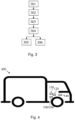
- Fig. 4 is a schematic block diagram showing a FCEV 400 comprising the cooling system 100, 200 described above.
- the cooling system 100, 200 can be applied in any type of FCEVs having air suspension system such as wagons, motor vehicles, cars, trucks, buses, railed vehicles e.g. trains, trams, watercraft e.g. ships, boats, amphibious vehicles e.g. screw-propelled vehicle, hovercraft, aircraft e.g. airplanes, helicopters, aerostat and spacecraft etc.
- Fig.l and 2 are only for illustration purpose.
- the positions and shapes of the first and second containers 101, 102 and the positions and shapes of the first, second and third valves 103, 105, 108 may vary depending on the actual application, situation, structure, and environment in the FCEVs.
- the cooling system 100, 200 of the present disclosure uses the compressed air generated from the existing compressed air system comprised in the fuel cell electric vehicle to drive the water spray generation.
- the cooling water is the condensates generated from the fuel cell system comprised in the fuel cell electric vehicle.
- Relative terms such as “below” or “above” or “upper” or “lower” or “horizontal” or “vertical” may be used herein to describe a relationship of one element to another element as illustrated in the Figures. It will be understood that these terms and those discussed above are intended to encompass different orientations of the device in addition to the orientation depicted in the Figures. It will be understood that when an element is referred to as being “connected” or “coupled” to another element, it can be directly connected or coupled to the other element, or intervening elements may be present. In contrast, when an element is referred to as being “directly connected” or “directly coupled” to another element, there are no intervening elements present.
Landscapes
- Engineering & Computer Science (AREA)
- Chemical & Material Sciences (AREA)
- Combustion & Propulsion (AREA)
- Transportation (AREA)
- Mechanical Engineering (AREA)
- Manufacturing & Machinery (AREA)
- Life Sciences & Earth Sciences (AREA)
- Sustainable Development (AREA)
- Sustainable Energy (AREA)
- Chemical Kinetics & Catalysis (AREA)
- Electrochemistry (AREA)
- General Chemical & Material Sciences (AREA)
- Electric Propulsion And Braking For Vehicles (AREA)
- Fuel Cell (AREA)
Abstract
A water spray cooling system (100), a cooling method for a fuel cell electric vehicle and a fuel cell electric vehicle (400) comprises the water spray cooling system (100) are disclosed. The cooling system (100) comprises a first storage container storing exhaust water generated from a fuel cell system (120) comprised in the fuel cell electric vehicle, a second storage container (102) connected to the first storage container (101) via a first valve (103); a first tube (104) connecting a first opening (112) of the second storage container (102) with an air tank (130) via a second valve (105). The air tank (130) comprises compressed air generated from a compressed air system comprised in the fuel cell electric vehicle. The cooling system (100) further comprises one or more water spray nozzles connected to a second opening of the second storage container through a second tube.
Description
- The disclosure relates generally to a compressed air driven evaporative cooling system. In particular aspects, the disclosure relates to a water spray cooling system for fuel cell electric vehicles.
- The disclosure can be applied in any fuel cell electric vehicles, such as cars, heavy-duty trucks, buses, construction equipment, marine vessels etc. Although the disclosure will be described with respect to a particular vehicle, the disclosure is not restricted to any particular vehicles.
- A fuel cell is a device that can produce electricity by converting chemical energy from a fuel into electrical energy through an electrochemical reaction within a fuel cell stack, instead of converting the chemical energy from the fuel into heat through combustion. Fuel cells can produce electricity continuously as long as fuel and oxygen are supplied. Fuel cells may provide power for small electric/electronic products, industries, households, and vehicles. A fuel cell electric vehicle (FCEV) is an electric vehicle that uses a fuel cell, sometimes in combination with a small battery or supercapacitor, to power its onboard electric motor. Fuel cells in vehicles generate electricity generally using oxygen from the air and compressed hydrogen.
- Cooling of FCEVs is a huge challenge, usually an upsized cooling system with an extreme power fan is needed. A fan with extreme power creates noise and uses up some of the electricity generated by the fuel cell (FC) leaving less for propulsion and increasing cost. Further, the FC needs a special deionized coolant and bigger radiators need to be manufactured in a special material adding further cost to the cooling system.
- The present disclosure provides a cooling system with reduced cost and size compared to the prior art solutions.
- According to a first aspect of the disclosure, a water spray cooling system for a fuel cell electric vehicle is provided. The cooling system comprises a first storage container configured to store exhaust water generated from a fuel cell system comprised in the fuel cell electric vehicle and a second storage container connected to the first storage container via a first valve. The cooling system further comprises a first tube connecting a first opening of the second storage container with an air tank via a second valve. The air tank comprises compressed air generated from a compressed air system comprised in the fuel cell electric vehicle. The cooling system further comprises one or more water spray nozzles connected to a second opening of the second storage container through a second tube. The first and second valves are configured to be controlled during a water spray event such that the first valve is first open to fill water from the first storage container to the second storage container and then closed, and after the first valve is closed, the second valve is open to deliver the compressed air from the air tank to the second storage container to create a water spray at the water spray nozzle.
- The water spray may be supplied to a radiator of the fuel cell system comprised in the fuel cell electric vehicle.
- In some examples, the second storage container may be smaller than the first storage container and have a water volume needed for one water spray event.
- According to some examples, the first and second storage containers are integrated as a two-chamber tank. A first chamber is the first storage container, a second chamber is the second storage container, and the first valve is a check valve and arranged between the two chambers.
- According to some examples, the sizes of the second storage container, the second tube and the water spray nozzle, as well as the open time of the second valve are configured such that the compressed air presses out all water in the second storage container, the second tube and the water spray nozzle during one water spray event.
- According to a second aspect of the disclosure, a fuel cell electric vehicle comprising the cooling system described above is provided.
- According to a third aspect of the disclosure, a cooling method for a fuel cell electric vehicle is provided. The cooling method comprises providing a first storage container configured to store exhaust water generated from a fuel cell system comprised in the fuel cell electric vehicle; providing a second storage container connected to the first storage container via a first valve; providing a first tube connecting a first opening of the second storage container with an air tank via a second valve, wherein the air tank comprises compressed air generated from a compressed air system comprised in the fuel cell electric vehicle; providing one or more water spray nozzles connected to a second opening of the second storage container through a second tube; and controlling the first and second valves during a water spray event such that the first valve is first open to fill water from the first storage container to the second storage container and then closed, and after the first valve is closed, the second valve is open to deliver the compressed air from the air tank to the second storage container to create a water spray at the water spray nozzle.
- According to some examples, the cooling method may further comprise controlling a third valve comprised in the second container to be open to the atmosphere during filling water from the first container to the second container.
- The cooling system of the present disclosure uses the compressed air generated from the existing compressed air system comprised in the fuel cell electric vehicle to drive the water spray generation. The cooling water is the condensates generated from the fuel cell system. There is an exhaust tank for condensates on a vehicle using fuel cells, so the vehicle produces its own cooling water. The exhaust tank could be pressurized with the compressed air if it was equipped with check valves. By using the condensates generated from the fuel cells and the compressed air generated from the existing compressed air system in the vehicle, the cooling system of the present disclosure has technical benefits on e.g. reusing existing energy and system, reduced cost and size compared to the prior art solutions.
- The above aspects, accompanying claims, and/or examples disclosed herein above and later below may be suitably combined with each other as would be apparent to anyone of ordinary skilled in the art.
- Additional features and advantages are disclosed in the following description, claims, and drawings, and in part will be readily apparent therefrom to those skilled in the art or recognized by practicing the disclosure as described herein.
- With reference to the appended drawings, below follows a more detailed description of aspects of the disclosure cited as examples.
-
Fig. 1 is a schematic block diagram showing an exemplary cooling system; -
Fig. 2 is a schematic block diagram showing another exemplary cooling system; -
Fig. 3 is a flow chart showing a cooling method for a fuel cell electric vehicle; and -
Fig. 4 is a schematic block diagram showing a FCEV. - Aspects set forth below represent the necessary information to enable those skilled in the art to practice the disclosure.
- Evaporative cooling is used in large scale in heat exchange facilities and has been proposed to be used also for cooling FCEVs. For example, for each kg of used hydrogen in the FC, 9 kg of water is produced so the FCEV produces its own cooling water. The FCEV exhaust is comparatively cold, so the exhaust cannot carry all of the water in gaseous form. The pressure to drive the water spray in different cooling applications is usually not very high, often in the range of 8-16 bar. FCEVs, e.g. vehicles with FCs, have a compressed air system or an air compressor so there are already 8-16 bar air pressure available on the vehicles. The primary function of the existing compressed air system in the vehicle is to supply compressed air for the vehicle air suspension and braking system.
- The proposal in the present disclosure is to use the compressed air available on the fuel cell electric vehicle to drive the water spray generation. There is an exhaust tank for condensates on the fuel cell electric vehicle. The exhaust tank could be pressurized with the compressed air if it was equipped with check valves.
-
Fig. 1 is a schematic block diagram showing an example of a waterspray cooling system 100 for a fuel cell electric vehicle. - The
cooling system 100 comprises afirst storage container 101 configured to store exhaust water generated from afuel cell system 120 comprised in the fuel cell electric vehicle. - The
cooling system 100 further comprises asecond storage container 102 connected to thefirst storage container 101 via afirst valve 103. - The
cooling system 100 further comprises afirst tube 104 connecting afirst opening 112 of thesecond storage container 102 with anair tank 130 via asecond valve 105. Theair tank 130 comprises compressed air generated from a compressed air system comprised in the fuel cell electric vehicle. - The
cooling system 100 further comprises one or morewater spray nozzles 106 connected to a second opening 113 of thesecond storage container 102 through asecond tube 107. - The first and
second valves water spray nozzle 106. The first andsecond valves first valve 103 is open to fill water from thefirst storage container 101 to thesecond storage container 102 and then closed, and after thefirst valve 103 is closed, thesecond valve 105 is open to deliver the compressed air from theair tank 130 to thesecond storage container 102 to create a water spray at thewater spray nozzle 106. - The water spray may be supplied to a
radiator 140 of the fuel cell system comprised in the fuel cell electric vehicle. The water spray may also be supplied to other circuits or equipment for lowing their temperature e.g. air conditioning, electric motors and power electronics etc. comprised in the fuel cell electric vehicle. - The
second storage container 102 is smaller than thefirst storage container 101 and has a water volume needed for generating one water spray event.
The sizes of thesecond storage container 102, thesecond tube 107 and thewater spray nozzle 106, as well as the open time of thesecond valve 105 are configured such that the compressed air presses out substantially all water in thesecond storage container 102, thesecond tube 107 and thewater spray nozzle 106 during one water spray event. - The
first valve 103 may be a check valve which does not need separate control. The check valve also called a one-way valve, is a device that allows the flow of fluids to move only in one direction. That is thefirst valve 103 allows the water flows from thefirst storage container 101 to thesecond storage container 102 and prevents the backflow from thesecond storage container 102 to thefirst storage container 101 when thesecond storage container 102 is pressurized. - The
first valve 103 may also be any type of a control valve. Thefirst valve 103 can be controlled to be open to fill the water from thefirst storage container 101 to thesecond storage container 102 and to be closed when thesecond storage container 102 is pressurized. - The
second valve 105 may be any type of a control valve. The timing of opening or closing of thesecond valve 105 is important. Thesecond valve 105 should be open long enough to blow out the water in thesecond container 102, in thesecond tube 107 and even more important the water in thewater spray nozzle 106 to avoid potential freezing. If thesecond valve 105 is open for too long time, it will waste the compressed air which cost energy to compress. Typically, thesecond valve 105 may be closed before all water in thesecond container 102 is ejected. When most of the water has been pressed out from thesecond container 102, it is filled with high pressure air which is sufficient to blow out the water in thesecond tube 107 andnozzle 106. For example, assume that thesecond container 102 is pressurized with 8 bar air during a first half of the water spray event, thesecond container 102 is half filled with 8 bar air. Then thesecond valve 105 is closed, the air in thesecond container 102 continues to press the water out of thesecond container 102. When all water has been pressed out from thesecond container 102, the 8 bar air may have been dropped to 4 bar. So there are still a lot of air pressure left to drain the water in thesecond tube 107 andnozzle 106. - The
second valve 105 may be controlled automatically by a signal from a controller. The opening or closing of thesecond valve 105 may be done by electrical, hydraulic or pneumatic actuators. Air-actuated valves are commonly used because of their simplicity, as they only require a compressed air supply, whereas electrically operated valves require additional cabling and switch gear, and hydraulically actuated valves required high pressure supply and return lines for the hydraulic fluid. - There may be a potential problem with water lock, i.e. if the compressed air does not blow the
second tube 107 and thewater spray nozzle 106 clean of water, there might be residual pressure in thesecond storage container 102 which may prevent the water filling from thefirst container 101 to thesecond container 102. To solve this potential problem, athird valve 108 may be implemented in thesecond container 102 opening to the atmosphere to get rid of a potential water lock. Thethird valve 108 may be controlled to be open to the atmosphere during filling water from thefirst container 101 to thesecond container 102. - The first, second and
third valves -
Fig. 2 is a schematic block diagram showing anotherexemplary cooling system 200 for a fuel cell electric vehicle. As shown inFig.2 , the first andsecond storage containers first chamber 201 and asecond chamber 202. Thefirst chamber 201 is thefirst storage container 101, thesecond chamber 202 is thesecond storage container 102, and thefirst valve 103 is arranged between the twochambers - A cooling method for a fuel cell electric vehicle will be described with reference to
Fig. 3 . The cooling method comprises the following steps, which may be performed in any suitable order. - 301: Providing a
first storage container 101 configured to store exhaust water generated from afuel cell system 120 comprised in the fuel cell electric vehicle. - 302: Providing a
second storage container 102 connected to thefirst storage container 101 via afirst valve 103. - 303: Providing a
first tube 104 connecting afirst opening 112 of thesecond storage container 102 with anair tank 130 via asecond valve 105, wherein theair tank 130 comprises compressed air generated from a compressed air system comprised in the fuel cell electric vehicle. - 304: Providing one or more
water spray nozzles 106 connected to asecond opening 113 of thesecond storage container 102 through asecond tube 107. - 305: Controlling the first and
second valves first valve 103 is first open to fill water from thefirst storage container 101 to thesecond storage container 102 and then closed, and after thefirst valve 103 is closed, thesecond valve 105 is open to deliver the compressed air from theair tank 130 to thesecond storage container 102 to create a water spray at thewater spray nozzle 106. - The cooling method may further comprise:
306: Controlling athird valve 108 comprised in thesecond container 102 to be open to the atmosphere during filling water from thefirst container 101 to thesecond container 102. - The
cooling system Fig. 4 is a schematic block diagram showing aFCEV 400 comprising thecooling system cooling system - It is notated that Fig.l and 2 are only for illustration purpose. The positions and shapes of the first and
second containers third valves - To summarize, the
cooling system - Some examples are listed in the following:
- Example 1: A water spray cooling system (100, 200) for a fuel cell electric vehicle (400), wherein the cooling system (100, 200) comprises:
- a first storage container (101) configured to store exhaust water generated from a fuel cell system (120) comprised in the fuel cell electric vehicle (400);
- a second storage container (102) connected to the first storage container (101) via a first valve (103);
- a first tube (104) connecting a first opening (112) of the second storage container (102) with an air tank (130) via a second valve (105), wherein the air tank (130) comprises compressed air generated from a compressed air system comprised in the fuel cell electric vehicle (400); and
- one or more water spray nozzles (106) connected to a second opening (113) of the second storage container (102) through a second tube (107); and wherein
- the first and second valves (103, 105) are configured to be controlled during a water spray event such that the first valve (103) is first open to fill water from the first storage container (101) to the second storage container (102) and then closed, and after the first valve (103) is closed, the second valve (105) is open to deliver the compressed air from the air tank (130) to the second storage container (102) to create a water spray at the water spray nozzle (106).
- Example 2: The cooling system (100, 200) according to Example 1, wherein the water spray is supplied to a radiator (140) of the fuel cell system comprised in the fuel cell electric vehicle (400).
- Example 3: The cooling system (100, 200) according to any one of Examples 1-2, wherein the second storage container (102) is smaller than the first storage container (101) and has a water volume needed for one water spray event.
- Example 4: The cooling system (100, 200) according to any one of Examples 1-3, wherein the first and second storage containers (101, 102) are integrated as a two-chamber (201, 202) tank, and wherein a first chamber (201) is the first storage container (101), a second chamber (202) is the second storage container (102), and the first valve (103) is arranged between the two chambers (201, 202).
- Example 5: The cooling system (100, 200) according to any one of Examples 1-4, wherein the first valve (103) is a check valve.
- Example 6: The cooling system (100, 200) according to any one of Examples 1-5, wherein the sizes of the second storage container (102), the second tube (107) and the water spray nozzle (106), as well as the open time of the second valve (105) are configured such that the compressed air presses out substantially all water in the second storage container (102), the second tube (107) and the water spray nozzle (106) during one water spray event.
- Example 7: The cooling system (100, 200) according to any one of Examples 1-6 further comprising a third valve (108) comprised in the second container (102), wherein the third valve (108) is controlled to be open to the atmosphere during filling water from the first container (101) to the second container (102).
- Example 8: A fuel cell electric vehicle (400) comprising a cooling system (100, 200) according to any one of Examples 1-7.
- Example 9: A cooling method for a fuel cell electric vehicle (400) comprising:
- providing (301) a first storage container (101) configured to store exhaust water generated from a fuel cell system (120) comprised in the fuel cell electric vehicle (400);
- providing (302) a second storage container (102) connected to the first storage container (101) via a first valve (103);
- providing (303) a first tube (104) connecting a first opening (112) of the second storage container (102) with an air tank (130) via a second valve (105), wherein the air tank (130) comprises compressed air generated from a compressed air system comprised in the fuel cell electric vehicle (400);
- providing (304) one or more water spray nozzles (106) connected to a second opening (113) of the second storage container (102) through a second tube (107);
- controlling (305) the first and second valves (103, 105) during a water spray event such that the first valve (103) is first open to fill water from the first storage container (101) to the second storage container (102) and then closed, and after the first valve (103) is closed, the second valve (105) is open to deliver the compressed air from the air tank (130) to the second storage container (102) to create a water spray at the water spray nozzle (106).
- Example 10: The cooling method according to Example 9, further comprises:
controlling (306) a third valve (108) comprised in the second container (102) to be open to the atmosphere during filling water from the first container (101) to the second container (102). - The terminology used herein is for the purpose of describing particular aspects only and is not intended to be limiting of the disclosure. As used herein, the singular forms "a," "an," and "the" are intended to include the plural forms as well, unless the context clearly indicates otherwise. As used herein, the term "and/or" includes any and all combinations of one or more of the associated listed items. It will be further understood that the terms "comprises," "comprising," "includes," and/or "including" when used herein specify the presence of stated features, integers, steps, operations, elements, and/or components, but do not preclude the presence or addition of one or more other features, integers, steps, operations, elements, components, and/or groups thereof.
- It will be understood that, although the terms first, second, etc., may be used herein to describe various elements, these elements should not be limited by these terms. These terms are only used to distinguish one element from another. For example, a first element could be termed a second element, and, similarly, a second element could be termed a first element without departing from the scope of the present disclosure.
- Relative terms such as "below" or "above" or "upper" or "lower" or "horizontal" or "vertical" may be used herein to describe a relationship of one element to another element as illustrated in the Figures. It will be understood that these terms and those discussed above are intended to encompass different orientations of the device in addition to the orientation depicted in the Figures. It will be understood that when an element is referred to as being "connected" or "coupled" to another element, it can be directly connected or coupled to the other element, or intervening elements may be present. In contrast, when an element is referred to as being "directly connected" or "directly coupled" to another element, there are no intervening elements present.
- Unless otherwise defined, all terms (including technical and scientific terms) used herein have the same meaning as commonly understood by one of ordinary skill in the art to which this disclosure belongs. It will be further understood that terms used herein should be interpreted as having a meaning consistent with their meaning in the context of this specification and the relevant art and will not be interpreted in an idealized or overly formal sense unless expressly so defined herein.
- It is to be understood that the present disclosure is not limited to the aspects described above and illustrated in the drawings; rather, the skilled person will recognize that many changes and modifications may be made within the scope of the present disclosure and appended claims. In the drawings and specification, there have been disclosed aspects for purposes of illustration only and not for purposes of limitation, the scope of the inventive concepts being set forth in the following claims.
Claims (10)
- A water spray cooling system (100, 200) for a fuel cell electric vehicle (400), wherein the cooling system (100, 200) comprises:a first storage container (101) configured to store exhaust water generated from a fuel cell system (120) comprised in the fuel cell electric vehicle (400);a second storage container (102) connected to the first storage container (101) via a first valve (103);a first tube (104) connecting a first opening (112) of the second storage container (102) with an air tank (130) via a second valve (105), wherein the air tank (130) comprises compressed air generated from a compressed air system comprised in the fuel cell electric vehicle (400); andone or more water spray nozzles (106) connected to a second opening (113) of the second storage container (102) through a second tube (107); and whereinthe first and second valves (103, 105) are configured to be controlled during a water spray event such that the first valve (103) is first open to fill water from the first storage container (101) to the second storage container (102) and then closed, and after the first valve (103) is closed, the second valve (105) is open to deliver the compressed air from the air tank (130) to the second storage container (102) to create a water spray at the water spray nozzle (106).
- The cooling system (100, 200) according to claim 1, wherein the water spray is supplied to a radiator (140) of the fuel cell system comprised in the fuel cell electric vehicle (400).
- The cooling system (100, 200) according to any one of claims 1-2, wherein the second storage container (102) is smaller than the first storage container (101) and has a water volume needed for one water spray event.
- The cooling system (100, 200) according to any one of claims 1-3, wherein the first and second storage containers (101, 102) are integrated as a two-chamber (201, 202) tank, and wherein a first chamber (201) is the first storage container (101), a second chamber (202) is the second storage container (102), and the first valve (103) is arranged between the two chambers (201, 202).
- The cooling system (100, 200) according to any one of claims 1-4, wherein the first valve (103) is a check valve.
- The cooling system (100, 200) according to any one of claims 1-5, wherein the sizes of the second storage container (102), the second tube (107) and the water spray nozzle (106), as well as the open time of the second valve (105) are configured such that the compressed air presses out substantially all water in the second storage container (102), the second tube (107) and the water spray nozzle (106) during one water spray event.
- The cooling system (100, 200) according to any one of claims 1-6 further comprising a third valve (108) comprised in the second container (102), wherein the third valve (108) is controlled to be open to the atmosphere during filling water from the first container (101) to the second container (102).
- A fuel cell electric vehicle (400) comprising a cooling system (100, 200) according to any one of claims 1-7.
- A cooling method for a fuel cell electric vehicle (400) comprising:providing (301) a first storage container (101) configured to store exhaust water generated from a fuel cell system (120) comprised in the fuel cell electric vehicle (400);providing (302) a second storage container (102) connected to the first storage container (101) via a first valve (103);providing (303) a first tube (104) connecting a first opening (112) of the second storage container (102) with an air tank (130) via a second valve (105), wherein the air tank (130) comprises compressed air generated from a compressed air system comprised in the fuel cell electric vehicle (400);providing (304) one or more water spray nozzles (106) connected to a second opening (113) of the second storage container (102) through a second tube (107);controlling (305) the first and second valves (103, 105) during a water spray event such that the first valve (103) is first open to fill water from the first storage container (101) to the second storage container (102) and then closed, and after the first valve (103) is closed, the second valve (105) is open to deliver the compressed air from the air tank (130) to the second storage container (102) to create a water spray at the water spray nozzle (106).
- The cooling method according to claim 9, further comprises controlling (306) a third valve (108) comprised in the second container (102) to be open to the atmosphere during filling water from the first container (101) to the second container (102).
Priority Applications (2)
| Application Number | Priority Date | Filing Date | Title |
|---|---|---|---|
| EP23155246.4A EP4414194A1 (en) | 2023-02-07 | 2023-02-07 | Compressed air driven evaporative cooling system |
| US18/432,691 US20240266558A1 (en) | 2023-02-07 | 2024-02-05 | Compressed air driven evaporative cooling system |
Applications Claiming Priority (1)
| Application Number | Priority Date | Filing Date | Title |
|---|---|---|---|
| EP23155246.4A EP4414194A1 (en) | 2023-02-07 | 2023-02-07 | Compressed air driven evaporative cooling system |
Publications (1)
| Publication Number | Publication Date |
|---|---|
| EP4414194A1 true EP4414194A1 (en) | 2024-08-14 |
Family
ID=85199471
Family Applications (1)
| Application Number | Title | Priority Date | Filing Date |
|---|---|---|---|
| EP23155246.4A Pending EP4414194A1 (en) | 2023-02-07 | 2023-02-07 | Compressed air driven evaporative cooling system |
Country Status (2)
| Country | Link |
|---|---|
| US (1) | US20240266558A1 (en) |
| EP (1) | EP4414194A1 (en) |
Citations (3)
| Publication number | Priority date | Publication date | Assignee | Title |
|---|---|---|---|---|
| EP1384967A2 (en) * | 2002-07-23 | 2004-01-28 | Deere & Company | Fuel cell cooling system |
| EP3614474A1 (en) * | 2018-08-24 | 2020-02-26 | Toyota Jidosha Kabushiki Kaisha | Fuel cell system |
| DE102020201046A1 (en) * | 2020-01-29 | 2021-07-29 | Robert Bosch Gesellschaft mit beschränkter Haftung | Compressed gas storage device for a motor vehicle, system with a motor vehicle and a cooling device, filling station for such a system and method for refueling a motor vehicle |
-
2023
- 2023-02-07 EP EP23155246.4A patent/EP4414194A1/en active Pending
-
2024
- 2024-02-05 US US18/432,691 patent/US20240266558A1/en active Pending
Patent Citations (3)
| Publication number | Priority date | Publication date | Assignee | Title |
|---|---|---|---|---|
| EP1384967A2 (en) * | 2002-07-23 | 2004-01-28 | Deere & Company | Fuel cell cooling system |
| EP3614474A1 (en) * | 2018-08-24 | 2020-02-26 | Toyota Jidosha Kabushiki Kaisha | Fuel cell system |
| DE102020201046A1 (en) * | 2020-01-29 | 2021-07-29 | Robert Bosch Gesellschaft mit beschränkter Haftung | Compressed gas storage device for a motor vehicle, system with a motor vehicle and a cooling device, filling station for such a system and method for refueling a motor vehicle |
Also Published As
| Publication number | Publication date |
|---|---|
| US20240266558A1 (en) | 2024-08-08 |
Similar Documents
| Publication | Publication Date | Title |
|---|---|---|
| US8492047B2 (en) | Hydrogen supply system for fuel cell and method for controlling the same | |
| US8197988B2 (en) | Hydrogen supply system for fuel cell | |
| US20230228381A1 (en) | Valve unit, on-tank valve and gas pressure tank system, in particular for fuel cell systems, and method for detecting a leakage | |
| US20250084967A1 (en) | Pressure vessel system | |
| US20230339351A1 (en) | Charging station, more particularly mobile charging station | |
| JP6951737B2 (en) | Hydrogen gas mobile system | |
| US11815050B2 (en) | Device for supplying fuel and vehicle comprising a device of this type | |
| US12370884B2 (en) | Pressurized gas tank receiving assembly for a motor vehicle | |
| US20240266558A1 (en) | Compressed air driven evaporative cooling system | |
| WO2022220717A1 (en) | Hydrogen storage arrangement | |
| US12580210B2 (en) | Hydrogen gas supply system | |
| US20060070790A1 (en) | Long range and ultralight vehicle body construction | |
| JP2005155869A (en) | Gas fuel filling method | |
| EP4317762A1 (en) | Tank and system for storing compressed gas, e.g. compressed hydrogen, vehicle and system and method for supplying gas to a tank | |
| JP2022022900A (en) | Fuel cell system and fuel cell system for vehicle | |
| CN119713112B (en) | High-hydrogen-utilization-rate rapid hydrogenation system and working method thereof | |
| WO2021249107A1 (en) | An expansion tank for a vehicle with dual cooling lines, a coolant system and a method for filling the expansion tank | |
| US20070283623A1 (en) | Compartmentalized Hydrogen Fueling System | |
| CN111923938B (en) | Waste heat utilization system and control method for hybrid power rail car | |
| Pehr et al. | Hydrogen—the fuel of the future—The BMW 750hl | |
| JP2022147126A (en) | Automobile | |
| EP4227606A1 (en) | Autonomous refrigerated container for storage and thermostatted transport of products | |
| CN217415957U (en) | Unmanned transport vehicle | |
| WO2020072238A1 (en) | Exothermic reaction energy system | |
| WO2014207757A1 (en) | Hydraulic regenerative energy storage system and method for passenger stock and freight wagons |
Legal Events
| Date | Code | Title | Description |
|---|---|---|---|
| PUAI | Public reference made under article 153(3) epc to a published international application that has entered the european phase |
Free format text: ORIGINAL CODE: 0009012 |
|
| STAA | Information on the status of an ep patent application or granted ep patent |
Free format text: STATUS: REQUEST FOR EXAMINATION WAS MADE |
|
| 17P | Request for examination filed |
Effective date: 20240502 |
|
| AK | Designated contracting states |
Kind code of ref document: A1 Designated state(s): AL AT BE BG CH CY CZ DE DK EE ES FI FR GB GR HR HU IE IS IT LI LT LU LV MC ME MK MT NL NO PL PT RO RS SE SI SK SM TR |