EP4414149A1 - Apparatuses, tacking sticks, and systems for tacking workpieces in composite manufacturing and methods associated therewith - Google Patents
Apparatuses, tacking sticks, and systems for tacking workpieces in composite manufacturing and methods associated therewith Download PDFInfo
- Publication number
- EP4414149A1 EP4414149A1 EP23216125.7A EP23216125A EP4414149A1 EP 4414149 A1 EP4414149 A1 EP 4414149A1 EP 23216125 A EP23216125 A EP 23216125A EP 4414149 A1 EP4414149 A1 EP 4414149A1
- Authority
- EP
- European Patent Office
- Prior art keywords
- actuating member
- tacking
- workpieces
- workpiece
- active position
- Prior art date
- Legal status (The legal status is an assumption and is not a legal conclusion. Google has not performed a legal analysis and makes no representation as to the accuracy of the status listed.)
- Pending
Links
Images









Classifications
-
- B—PERFORMING OPERATIONS; TRANSPORTING
- B29—WORKING OF PLASTICS; WORKING OF SUBSTANCES IN A PLASTIC STATE IN GENERAL
- B29C—SHAPING OR JOINING OF PLASTICS; SHAPING OF MATERIAL IN A PLASTIC STATE, NOT OTHERWISE PROVIDED FOR; AFTER-TREATMENT OF THE SHAPED PRODUCTS, e.g. REPAIRING
- B29C66/00—General aspects of processes or apparatus for joining preformed parts
- B29C66/80—General aspects of machine operations or constructions and parts thereof
- B29C66/82—Pressure application arrangements, e.g. transmission or actuating mechanisms for joining tools or clamps
- B29C66/824—Actuating mechanisms
-
- B—PERFORMING OPERATIONS; TRANSPORTING
- B64—AIRCRAFT; AVIATION; COSMONAUTICS
- B64F—GROUND OR AIRCRAFT-CARRIER-DECK INSTALLATIONS SPECIALLY ADAPTED FOR USE IN CONNECTION WITH AIRCRAFT; DESIGNING, MANUFACTURING, ASSEMBLING, CLEANING, MAINTAINING OR REPAIRING AIRCRAFT, NOT OTHERWISE PROVIDED FOR; HANDLING, TRANSPORTING, TESTING OR INSPECTING AIRCRAFT COMPONENTS, NOT OTHERWISE PROVIDED FOR
- B64F5/00—Designing, manufacturing, assembling, cleaning, maintaining or repairing aircraft, not otherwise provided for; Handling, transporting, testing or inspecting aircraft components, not otherwise provided for
- B64F5/10—Manufacturing or assembling aircraft, e.g. jigs therefor
-
- B—PERFORMING OPERATIONS; TRANSPORTING
- B29—WORKING OF PLASTICS; WORKING OF SUBSTANCES IN A PLASTIC STATE IN GENERAL
- B29C—SHAPING OR JOINING OF PLASTICS; SHAPING OF MATERIAL IN A PLASTIC STATE, NOT OTHERWISE PROVIDED FOR; AFTER-TREATMENT OF THE SHAPED PRODUCTS, e.g. REPAIRING
- B29C65/00—Joining or sealing of preformed parts, e.g. welding of plastics materials; Apparatus therefor
- B29C65/02—Joining or sealing of preformed parts, e.g. welding of plastics materials; Apparatus therefor by heating, with or without pressure
- B29C65/18—Joining or sealing of preformed parts, e.g. welding of plastics materials; Apparatus therefor by heating, with or without pressure using heated tools
-
- B—PERFORMING OPERATIONS; TRANSPORTING
- B29—WORKING OF PLASTICS; WORKING OF SUBSTANCES IN A PLASTIC STATE IN GENERAL
- B29C—SHAPING OR JOINING OF PLASTICS; SHAPING OF MATERIAL IN A PLASTIC STATE, NOT OTHERWISE PROVIDED FOR; AFTER-TREATMENT OF THE SHAPED PRODUCTS, e.g. REPAIRING
- B29C65/00—Joining or sealing of preformed parts, e.g. welding of plastics materials; Apparatus therefor
- B29C65/02—Joining or sealing of preformed parts, e.g. welding of plastics materials; Apparatus therefor by heating, with or without pressure
- B29C65/18—Joining or sealing of preformed parts, e.g. welding of plastics materials; Apparatus therefor by heating, with or without pressure using heated tools
- B29C65/20—Joining or sealing of preformed parts, e.g. welding of plastics materials; Apparatus therefor by heating, with or without pressure using heated tools with direct contact, e.g. using "mirror"
-
- B—PERFORMING OPERATIONS; TRANSPORTING
- B29—WORKING OF PLASTICS; WORKING OF SUBSTANCES IN A PLASTIC STATE IN GENERAL
- B29C—SHAPING OR JOINING OF PLASTICS; SHAPING OF MATERIAL IN A PLASTIC STATE, NOT OTHERWISE PROVIDED FOR; AFTER-TREATMENT OF THE SHAPED PRODUCTS, e.g. REPAIRING
- B29C65/00—Joining or sealing of preformed parts, e.g. welding of plastics materials; Apparatus therefor
- B29C65/02—Joining or sealing of preformed parts, e.g. welding of plastics materials; Apparatus therefor by heating, with or without pressure
- B29C65/18—Joining or sealing of preformed parts, e.g. welding of plastics materials; Apparatus therefor by heating, with or without pressure using heated tools
- B29C65/24—Joining or sealing of preformed parts, e.g. welding of plastics materials; Apparatus therefor by heating, with or without pressure using heated tools characterised by the means for heating the tool
- B29C65/30—Electrical means
-
- B—PERFORMING OPERATIONS; TRANSPORTING
- B29—WORKING OF PLASTICS; WORKING OF SUBSTANCES IN A PLASTIC STATE IN GENERAL
- B29C—SHAPING OR JOINING OF PLASTICS; SHAPING OF MATERIAL IN A PLASTIC STATE, NOT OTHERWISE PROVIDED FOR; AFTER-TREATMENT OF THE SHAPED PRODUCTS, e.g. REPAIRING
- B29C66/00—General aspects of processes or apparatus for joining preformed parts
- B29C66/01—General aspects dealing with the joint area or with the area to be joined
- B29C66/05—Particular design of joint configurations
- B29C66/10—Particular design of joint configurations particular design of the joint cross-sections
- B29C66/11—Joint cross-sections comprising a single joint-segment, i.e. one of the parts to be joined comprising a single joint-segment in the joint cross-section
- B29C66/112—Single lapped joints
- B29C66/1122—Single lap to lap joints, i.e. overlap joints
-
- B—PERFORMING OPERATIONS; TRANSPORTING
- B29—WORKING OF PLASTICS; WORKING OF SUBSTANCES IN A PLASTIC STATE IN GENERAL
- B29C—SHAPING OR JOINING OF PLASTICS; SHAPING OF MATERIAL IN A PLASTIC STATE, NOT OTHERWISE PROVIDED FOR; AFTER-TREATMENT OF THE SHAPED PRODUCTS, e.g. REPAIRING
- B29C66/00—General aspects of processes or apparatus for joining preformed parts
- B29C66/01—General aspects dealing with the joint area or with the area to be joined
- B29C66/05—Particular design of joint configurations
- B29C66/20—Particular design of joint configurations particular design of the joint lines, e.g. of the weld lines
- B29C66/21—Particular design of joint configurations particular design of the joint lines, e.g. of the weld lines said joint lines being formed by a single dot or dash or by several dots or dashes, i.e. spot joining or spot welding
-
- B—PERFORMING OPERATIONS; TRANSPORTING
- B29—WORKING OF PLASTICS; WORKING OF SUBSTANCES IN A PLASTIC STATE IN GENERAL
- B29C—SHAPING OR JOINING OF PLASTICS; SHAPING OF MATERIAL IN A PLASTIC STATE, NOT OTHERWISE PROVIDED FOR; AFTER-TREATMENT OF THE SHAPED PRODUCTS, e.g. REPAIRING
- B29C66/00—General aspects of processes or apparatus for joining preformed parts
- B29C66/40—General aspects of joining substantially flat articles, e.g. plates, sheets or web-like materials; Making flat seams in tubular or hollow articles; Joining single elements to substantially flat surfaces
- B29C66/41—Joining substantially flat articles ; Making flat seams in tubular or hollow articles
- B29C66/45—Joining of substantially the whole surface of the articles
-
- B—PERFORMING OPERATIONS; TRANSPORTING
- B29—WORKING OF PLASTICS; WORKING OF SUBSTANCES IN A PLASTIC STATE IN GENERAL
- B29C—SHAPING OR JOINING OF PLASTICS; SHAPING OF MATERIAL IN A PLASTIC STATE, NOT OTHERWISE PROVIDED FOR; AFTER-TREATMENT OF THE SHAPED PRODUCTS, e.g. REPAIRING
- B29C66/00—General aspects of processes or apparatus for joining preformed parts
- B29C66/70—General aspects of processes or apparatus for joining preformed parts characterised by the composition, physical properties or the structure of the material of the parts to be joined; Joining with non-plastics material
- B29C66/72—General aspects of processes or apparatus for joining preformed parts characterised by the composition, physical properties or the structure of the material of the parts to be joined; Joining with non-plastics material characterised by the structure of the material of the parts to be joined
- B29C66/721—Fibre-reinforced materials
-
- B—PERFORMING OPERATIONS; TRANSPORTING
- B29—WORKING OF PLASTICS; WORKING OF SUBSTANCES IN A PLASTIC STATE IN GENERAL
- B29C—SHAPING OR JOINING OF PLASTICS; SHAPING OF MATERIAL IN A PLASTIC STATE, NOT OTHERWISE PROVIDED FOR; AFTER-TREATMENT OF THE SHAPED PRODUCTS, e.g. REPAIRING
- B29C66/00—General aspects of processes or apparatus for joining preformed parts
- B29C66/70—General aspects of processes or apparatus for joining preformed parts characterised by the composition, physical properties or the structure of the material of the parts to be joined; Joining with non-plastics material
- B29C66/73—General aspects of processes or apparatus for joining preformed parts characterised by the composition, physical properties or the structure of the material of the parts to be joined; Joining with non-plastics material characterised by the intensive physical properties of the material of the parts to be joined, by the optical properties of the material of the parts to be joined, by the extensive physical properties of the parts to be joined, by the state of the material of the parts to be joined or by the material of the parts to be joined being a thermoplastic or a thermoset
- B29C66/739—General aspects of processes or apparatus for joining preformed parts characterised by the composition, physical properties or the structure of the material of the parts to be joined; Joining with non-plastics material characterised by the intensive physical properties of the material of the parts to be joined, by the optical properties of the material of the parts to be joined, by the extensive physical properties of the parts to be joined, by the state of the material of the parts to be joined or by the material of the parts to be joined being a thermoplastic or a thermoset characterised by the material of the parts to be joined being a thermoplastic or a thermoset
- B29C66/7392—General aspects of processes or apparatus for joining preformed parts characterised by the composition, physical properties or the structure of the material of the parts to be joined; Joining with non-plastics material characterised by the intensive physical properties of the material of the parts to be joined, by the optical properties of the material of the parts to be joined, by the extensive physical properties of the parts to be joined, by the state of the material of the parts to be joined or by the material of the parts to be joined being a thermoplastic or a thermoset characterised by the material of the parts to be joined being a thermoplastic or a thermoset characterised by the material of at least one of the parts being a thermoplastic
-
- B—PERFORMING OPERATIONS; TRANSPORTING
- B29—WORKING OF PLASTICS; WORKING OF SUBSTANCES IN A PLASTIC STATE IN GENERAL
- B29C—SHAPING OR JOINING OF PLASTICS; SHAPING OF MATERIAL IN A PLASTIC STATE, NOT OTHERWISE PROVIDED FOR; AFTER-TREATMENT OF THE SHAPED PRODUCTS, e.g. REPAIRING
- B29C66/00—General aspects of processes or apparatus for joining preformed parts
- B29C66/80—General aspects of machine operations or constructions and parts thereof
- B29C66/81—General aspects of the pressing elements, i.e. the elements applying pressure on the parts to be joined in the area to be joined, e.g. the welding jaws or clamps
- B29C66/812—General aspects of the pressing elements, i.e. the elements applying pressure on the parts to be joined in the area to be joined, e.g. the welding jaws or clamps characterised by the composition, by the structure, by the intensive physical properties or by the optical properties of the material constituting the pressing elements, e.g. constituting the welding jaws or clamps
- B29C66/8126—General aspects of the pressing elements, i.e. the elements applying pressure on the parts to be joined in the area to be joined, e.g. the welding jaws or clamps characterised by the composition, by the structure, by the intensive physical properties or by the optical properties of the material constituting the pressing elements, e.g. constituting the welding jaws or clamps characterised by the intensive physical properties or by the optical properties of the material constituting the pressing elements, e.g. constituting the welding jaws or clamps
- B29C66/81261—Thermal properties, e.g. thermal conductivity, thermal expansion coefficient
-
- B—PERFORMING OPERATIONS; TRANSPORTING
- B29—WORKING OF PLASTICS; WORKING OF SUBSTANCES IN A PLASTIC STATE IN GENERAL
- B29C—SHAPING OR JOINING OF PLASTICS; SHAPING OF MATERIAL IN A PLASTIC STATE, NOT OTHERWISE PROVIDED FOR; AFTER-TREATMENT OF THE SHAPED PRODUCTS, e.g. REPAIRING
- B29C66/00—General aspects of processes or apparatus for joining preformed parts
- B29C66/80—General aspects of machine operations or constructions and parts thereof
- B29C66/81—General aspects of the pressing elements, i.e. the elements applying pressure on the parts to be joined in the area to be joined, e.g. the welding jaws or clamps
- B29C66/812—General aspects of the pressing elements, i.e. the elements applying pressure on the parts to be joined in the area to be joined, e.g. the welding jaws or clamps characterised by the composition, by the structure, by the intensive physical properties or by the optical properties of the material constituting the pressing elements, e.g. constituting the welding jaws or clamps
- B29C66/8126—General aspects of the pressing elements, i.e. the elements applying pressure on the parts to be joined in the area to be joined, e.g. the welding jaws or clamps characterised by the composition, by the structure, by the intensive physical properties or by the optical properties of the material constituting the pressing elements, e.g. constituting the welding jaws or clamps characterised by the intensive physical properties or by the optical properties of the material constituting the pressing elements, e.g. constituting the welding jaws or clamps
- B29C66/81264—Mechanical properties, e.g. hardness
-
- B—PERFORMING OPERATIONS; TRANSPORTING
- B29—WORKING OF PLASTICS; WORKING OF SUBSTANCES IN A PLASTIC STATE IN GENERAL
- B29C—SHAPING OR JOINING OF PLASTICS; SHAPING OF MATERIAL IN A PLASTIC STATE, NOT OTHERWISE PROVIDED FOR; AFTER-TREATMENT OF THE SHAPED PRODUCTS, e.g. REPAIRING
- B29C66/00—General aspects of processes or apparatus for joining preformed parts
- B29C66/80—General aspects of machine operations or constructions and parts thereof
- B29C66/81—General aspects of the pressing elements, i.e. the elements applying pressure on the parts to be joined in the area to be joined, e.g. the welding jaws or clamps
- B29C66/814—General aspects of the pressing elements, i.e. the elements applying pressure on the parts to be joined in the area to be joined, e.g. the welding jaws or clamps characterised by the design of the pressing elements, e.g. of the welding jaws or clamps
- B29C66/8145—General aspects of the pressing elements, i.e. the elements applying pressure on the parts to be joined in the area to be joined, e.g. the welding jaws or clamps characterised by the design of the pressing elements, e.g. of the welding jaws or clamps characterised by the constructional aspects of the pressing elements, e.g. of the welding jaws or clamps
- B29C66/81453—General aspects of the pressing elements, i.e. the elements applying pressure on the parts to be joined in the area to be joined, e.g. the welding jaws or clamps characterised by the design of the pressing elements, e.g. of the welding jaws or clamps characterised by the constructional aspects of the pressing elements, e.g. of the welding jaws or clamps being made of flexible slats, flexible fins, flexible bristles or springs, e.g. coiled springs
-
- B—PERFORMING OPERATIONS; TRANSPORTING
- B29—WORKING OF PLASTICS; WORKING OF SUBSTANCES IN A PLASTIC STATE IN GENERAL
- B29C—SHAPING OR JOINING OF PLASTICS; SHAPING OF MATERIAL IN A PLASTIC STATE, NOT OTHERWISE PROVIDED FOR; AFTER-TREATMENT OF THE SHAPED PRODUCTS, e.g. REPAIRING
- B29C66/00—General aspects of processes or apparatus for joining preformed parts
- B29C66/80—General aspects of machine operations or constructions and parts thereof
- B29C66/81—General aspects of the pressing elements, i.e. the elements applying pressure on the parts to be joined in the area to be joined, e.g. the welding jaws or clamps
- B29C66/814—General aspects of the pressing elements, i.e. the elements applying pressure on the parts to be joined in the area to be joined, e.g. the welding jaws or clamps characterised by the design of the pressing elements, e.g. of the welding jaws or clamps
- B29C66/8145—General aspects of the pressing elements, i.e. the elements applying pressure on the parts to be joined in the area to be joined, e.g. the welding jaws or clamps characterised by the design of the pressing elements, e.g. of the welding jaws or clamps characterised by the constructional aspects of the pressing elements, e.g. of the welding jaws or clamps
- B29C66/81463—General aspects of the pressing elements, i.e. the elements applying pressure on the parts to be joined in the area to be joined, e.g. the welding jaws or clamps characterised by the design of the pressing elements, e.g. of the welding jaws or clamps characterised by the constructional aspects of the pressing elements, e.g. of the welding jaws or clamps comprising a plurality of single pressing elements, e.g. a plurality of sonotrodes, or comprising a plurality of single counter-pressing elements, e.g. a plurality of anvils, said plurality of said single elements being suitable for making a single joint
-
- B—PERFORMING OPERATIONS; TRANSPORTING
- B29—WORKING OF PLASTICS; WORKING OF SUBSTANCES IN A PLASTIC STATE IN GENERAL
- B29C—SHAPING OR JOINING OF PLASTICS; SHAPING OF MATERIAL IN A PLASTIC STATE, NOT OTHERWISE PROVIDED FOR; AFTER-TREATMENT OF THE SHAPED PRODUCTS, e.g. REPAIRING
- B29C66/00—General aspects of processes or apparatus for joining preformed parts
- B29C66/80—General aspects of machine operations or constructions and parts thereof
- B29C66/82—Pressure application arrangements, e.g. transmission or actuating mechanisms for joining tools or clamps
- B29C66/822—Transmission mechanisms
- B29C66/8227—Transmission mechanisms using springs
-
- B—PERFORMING OPERATIONS; TRANSPORTING
- B29—WORKING OF PLASTICS; WORKING OF SUBSTANCES IN A PLASTIC STATE IN GENERAL
- B29C—SHAPING OR JOINING OF PLASTICS; SHAPING OF MATERIAL IN A PLASTIC STATE, NOT OTHERWISE PROVIDED FOR; AFTER-TREATMENT OF THE SHAPED PRODUCTS, e.g. REPAIRING
- B29C66/00—General aspects of processes or apparatus for joining preformed parts
- B29C66/80—General aspects of machine operations or constructions and parts thereof
- B29C66/82—Pressure application arrangements, e.g. transmission or actuating mechanisms for joining tools or clamps
- B29C66/828—Other pressure application arrangements
-
- B—PERFORMING OPERATIONS; TRANSPORTING
- B29—WORKING OF PLASTICS; WORKING OF SUBSTANCES IN A PLASTIC STATE IN GENERAL
- B29C—SHAPING OR JOINING OF PLASTICS; SHAPING OF MATERIAL IN A PLASTIC STATE, NOT OTHERWISE PROVIDED FOR; AFTER-TREATMENT OF THE SHAPED PRODUCTS, e.g. REPAIRING
- B29C66/00—General aspects of processes or apparatus for joining preformed parts
- B29C66/80—General aspects of machine operations or constructions and parts thereof
- B29C66/83—General aspects of machine operations or constructions and parts thereof characterised by the movement of the joining or pressing tools
- B29C66/832—Reciprocating joining or pressing tools
-
- B—PERFORMING OPERATIONS; TRANSPORTING
- B29—WORKING OF PLASTICS; WORKING OF SUBSTANCES IN A PLASTIC STATE IN GENERAL
- B29C—SHAPING OR JOINING OF PLASTICS; SHAPING OF MATERIAL IN A PLASTIC STATE, NOT OTHERWISE PROVIDED FOR; AFTER-TREATMENT OF THE SHAPED PRODUCTS, e.g. REPAIRING
- B29C66/00—General aspects of processes or apparatus for joining preformed parts
- B29C66/80—General aspects of machine operations or constructions and parts thereof
- B29C66/83—General aspects of machine operations or constructions and parts thereof characterised by the movement of the joining or pressing tools
- B29C66/832—Reciprocating joining or pressing tools
- B29C66/8324—Joining or pressing tools pivoting around one axis
-
- F—MECHANICAL ENGINEERING; LIGHTING; HEATING; WEAPONS; BLASTING
- F03—MACHINES OR ENGINES FOR LIQUIDS; WIND, SPRING, OR WEIGHT MOTORS; PRODUCING MECHANICAL POWER OR A REACTIVE PROPULSIVE THRUST, NOT OTHERWISE PROVIDED FOR
- F03G—SPRING, WEIGHT, INERTIA OR LIKE MOTORS; MECHANICAL-POWER PRODUCING DEVICES OR MECHANISMS, NOT OTHERWISE PROVIDED FOR OR USING ENERGY SOURCES NOT OTHERWISE PROVIDED FOR
- F03G7/00—Mechanical-power-producing mechanisms, not otherwise provided for or using energy sources not otherwise provided for
- F03G7/06—Mechanical-power-producing mechanisms, not otherwise provided for or using energy sources not otherwise provided for using expansion or contraction of bodies due to heating, cooling, moistening, drying or the like
- F03G7/061—Mechanical-power-producing mechanisms, not otherwise provided for or using energy sources not otherwise provided for using expansion or contraction of bodies due to heating, cooling, moistening, drying or the like characterised by the actuating element
- F03G7/0614—Mechanical-power-producing mechanisms, not otherwise provided for or using energy sources not otherwise provided for using expansion or contraction of bodies due to heating, cooling, moistening, drying or the like characterised by the actuating element using shape memory elements
-
- F—MECHANICAL ENGINEERING; LIGHTING; HEATING; WEAPONS; BLASTING
- F03—MACHINES OR ENGINES FOR LIQUIDS; WIND, SPRING, OR WEIGHT MOTORS; PRODUCING MECHANICAL POWER OR A REACTIVE PROPULSIVE THRUST, NOT OTHERWISE PROVIDED FOR
- F03G—SPRING, WEIGHT, INERTIA OR LIKE MOTORS; MECHANICAL-POWER PRODUCING DEVICES OR MECHANISMS, NOT OTHERWISE PROVIDED FOR OR USING ENERGY SOURCES NOT OTHERWISE PROVIDED FOR
- F03G7/00—Mechanical-power-producing mechanisms, not otherwise provided for or using energy sources not otherwise provided for
- F03G7/06—Mechanical-power-producing mechanisms, not otherwise provided for or using energy sources not otherwise provided for using expansion or contraction of bodies due to heating, cooling, moistening, drying or the like
- F03G7/063—Mechanical-power-producing mechanisms, not otherwise provided for or using energy sources not otherwise provided for using expansion or contraction of bodies due to heating, cooling, moistening, drying or the like characterised by the mechanic interaction
- F03G7/06324—Mechanical-power-producing mechanisms, not otherwise provided for or using energy sources not otherwise provided for using expansion or contraction of bodies due to heating, cooling, moistening, drying or the like characterised by the mechanic interaction increasing or decreasing in volume
-
- F—MECHANICAL ENGINEERING; LIGHTING; HEATING; WEAPONS; BLASTING
- F03—MACHINES OR ENGINES FOR LIQUIDS; WIND, SPRING, OR WEIGHT MOTORS; PRODUCING MECHANICAL POWER OR A REACTIVE PROPULSIVE THRUST, NOT OTHERWISE PROVIDED FOR
- F03G—SPRING, WEIGHT, INERTIA OR LIKE MOTORS; MECHANICAL-POWER PRODUCING DEVICES OR MECHANISMS, NOT OTHERWISE PROVIDED FOR OR USING ENERGY SOURCES NOT OTHERWISE PROVIDED FOR
- F03G7/00—Mechanical-power-producing mechanisms, not otherwise provided for or using energy sources not otherwise provided for
- F03G7/06—Mechanical-power-producing mechanisms, not otherwise provided for or using energy sources not otherwise provided for using expansion or contraction of bodies due to heating, cooling, moistening, drying or the like
- F03G7/064—Mechanical-power-producing mechanisms, not otherwise provided for or using energy sources not otherwise provided for using expansion or contraction of bodies due to heating, cooling, moistening, drying or the like characterised by its use
- F03G7/0645—Clamping, fixing or crimping parts
-
- B—PERFORMING OPERATIONS; TRANSPORTING
- B29—WORKING OF PLASTICS; WORKING OF SUBSTANCES IN A PLASTIC STATE IN GENERAL
- B29C—SHAPING OR JOINING OF PLASTICS; SHAPING OF MATERIAL IN A PLASTIC STATE, NOT OTHERWISE PROVIDED FOR; AFTER-TREATMENT OF THE SHAPED PRODUCTS, e.g. REPAIRING
- B29C66/00—General aspects of processes or apparatus for joining preformed parts
- B29C66/80—General aspects of machine operations or constructions and parts thereof
- B29C66/82—Pressure application arrangements, e.g. transmission or actuating mechanisms for joining tools or clamps
- B29C66/828—Other pressure application arrangements
- B29C66/8284—Other pressure application arrangements using the thermal expansion of the joining tool
-
- B—PERFORMING OPERATIONS; TRANSPORTING
- B29—WORKING OF PLASTICS; WORKING OF SUBSTANCES IN A PLASTIC STATE IN GENERAL
- B29L—INDEXING SCHEME ASSOCIATED WITH SUBCLASS B29C, RELATING TO PARTICULAR ARTICLES
- B29L2031/00—Other particular articles
- B29L2031/30—Vehicles, e.g. ships or aircraft, or body parts thereof
- B29L2031/3055—Cars
-
- B—PERFORMING OPERATIONS; TRANSPORTING
- B29—WORKING OF PLASTICS; WORKING OF SUBSTANCES IN A PLASTIC STATE IN GENERAL
- B29L—INDEXING SCHEME ASSOCIATED WITH SUBCLASS B29C, RELATING TO PARTICULAR ARTICLES
- B29L2031/00—Other particular articles
- B29L2031/30—Vehicles, e.g. ships or aircraft, or body parts thereof
- B29L2031/3076—Aircrafts
-
- B—PERFORMING OPERATIONS; TRANSPORTING
- B29—WORKING OF PLASTICS; WORKING OF SUBSTANCES IN A PLASTIC STATE IN GENERAL
- B29L—INDEXING SCHEME ASSOCIATED WITH SUBCLASS B29C, RELATING TO PARTICULAR ARTICLES
- B29L2031/00—Other particular articles
- B29L2031/30—Vehicles, e.g. ships or aircraft, or body parts thereof
- B29L2031/3097—Cosmonautical vehicles; Rockets
Definitions
- the present disclosure relates generally to tacking workpieces in composite manufacturing and, particularly, to various examples of tacking elements, tacking sticks, and systems for tacking workpieces in composite manufacturing.
- Various examples of methods for tacking workpieces in composite manufacturing are also disclosed.
- applications of tacking workpieces can be used to tack plies of dry reinforcement fabric for composite materials used in aircraft.
- Applications to other types of workpieces, various types of composite materials, and other types of products are also contemplated.
- Manual and automated tacking approaches are used in producing composite parts from dry fabrics.
- the manual approach relies on an operator with a soldering iron to perform tacking of adjacent plies of dry fabric.
- the automated approach uses cartridge style heating elements to perform localized tacking of the adjacent plies.
- the cartridge style heating elements are long and difficult to integrate into automated production methods.
- Another drawback of cartridge style heating elements is that cooling is slow which requires removal of the heating surface from the material after a few seconds.
- the heating element may be left on during tacking operations due to the slow heating and cooling of the cartridge style heating element. This is not an efficient use of energy.
- the disclosed system for tacking workpieces in composite manufacturing includes an end effector, a mechanical arm and a computerized control system.
- the end effector includes a tacking stick.
- the tacking stick includes a support structure and a plurality of tacking elements.
- the support structure includes a contact surface.
- the plurality of tacking elements are embedded in the support structure and extend through the contact surface of the support structure.
- Each tacking element includes a base member, an actuating member with shape memory, and a heating member.
- the actuating member is at least partially secured to the base member.
- the heating member disposed on at least one of the base member and the actuating member.
- the mechanical arm configured to receive the end effector.
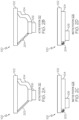
- Figs. 1A-D , 2A-D , 3A-B , 4A-D , 5 and 12-15 by way of examples, the present disclosure is directed to a tacking element 100 for tacking workpieces in composite manufacturing.
- Fig. 1A discloses an example of the tacking element 100 that includes a base member 102, an actuating member 104 and a heating member 106.
- Figs. 2A-D , 3A-B , 4A-D , 5 and 12-15 disclose various examples of the tacking element 100.
- a tacking element 100 for tacking workpieces in composite manufacturing includes a base member 102, an actuating member 104 at least partially secured to the base member 102, and a heating member 106 disposed on at least one of the base member 102 and the actuating member 104.
- the heating member configured to selectively radiate heat toward the actuating member 104.
- the actuating member 104 is configured to transform from an inactive position 108 to an active position 110 in response to the heat from the heating member 106.
- the actuating member 104 includes a shape memory alloy.
- the shape memory alloy includes aluminium (Al), cadmium (Cd), copper (Cu), gold (Au), iron (Fe), manganese (Mn), nickel (Ni), silicon (Si), titanium (Ti), zinc (Zn) or any suitable material with shape memory in any suitable combination.
- the shape memory alloy includes nickel-titanium (Ni-Ti), copper-aluminum-nickel (Cu-Al-Ni), copper-zinc-aluminum (Cu-Zn-Al), iron-manganese-silicon (Fe-Mn-Si), gold-cadmium (Au-Cd), or any suitable shape memory alloy.
- the actuating member 104 is configured to transform to the active position 110 in response to the heat reaching a predetermined temperature.
- the predetermined temperature may range from 200° C to 280 ° C.
- the predetermined head may be up to 300 ° C.
- the tacking element 100 is configured to be disposed such that the active position 110 of the actuating member 104 is proximate to a work surface 112 of a first workpiece 114 of a stack of workpieces 116.
- the tacking element 100 is configured to locally tack the first workpiece 114 to at least an adjacent workpiece 118 of the stack of workpieces 116 in response to at least one of the actuating member 104 and the heating member 106 being disposed proximate to the work surface 112 of the first workpiece 114 while the actuating member 104 is in the active position 110.
- a given workpiece e.g., first workpiece 114
- the stack of workpieces 116 may also be referred to as a stack of plies.
- a given ply may be referred to as a reinforcement fabric that includes carbon fibers and/or other types of suitable fibers.
- the tacking element 100 is configured to locally tack the first workpiece 114 to at least an adjacent workpiece 118 of the stack of workpieces 116 in response to at least one of the actuating member 104 and the heating member 106 contacting the work surface 112 of the first workpiece 114 while the actuating member 104is in the active position 110.
- the tacking element 100 is configured to locally compress the stack of workpieces 116 in response to at least one of the actuating member 104 and the heating member 106 contacting the work surface 112 of the first workpiece 114 while the actuating member 104 is in the active position 110.
- the actuating member 104 may be constructed of material capable of applying up to approximately 75 Kilopascal (kPa) units of pressure to the work surface 112 of the first workpiece 114.
- the tacking element 100 is configured to locally compact the stack of workpieces 116 in response to at least one of the actuating member 104 and the heating member 106 contacting the work surface 112 of the first workpiece 114 while the actuating member 104 is in the active position 110.
- the actuating member 104 may be constructed of material capable of applying up to approximately 75 kPa units of pressure to the work surface 112 of the first workpiece 114.
- the tacking element 100 is configured to transform the actuating member 104 from the active position 110 to the inactive position 108 using at least one of a biasing spring 202, a shape memory effect associated with the actuating member 104, a second actuating member 204 with shape memory, and an insert 302 fitted for compression of the actuating member 104 in any suitable combination.
- An example of the shape memory effect associated with the actuating member 104 is where the actuating member 104 includes a shape memory alloy capable of being trained to exhibit multiple shape memory effects.
- a first shape memory effect is triggered by the heating member 106 and transforms the actuating member 104 from an inactive position to an active position for the tacking operation.
- a second shape memory effect is triggered by a lower temperature that transforms the actuating member 104 from the active position to the inactive position after the tacking operation.
- a second actuating member 204 with shape memory is a second actuating member 204 that includes a shape memory alloy that is trained to be triggered to apply a force that transforms the actuating member 204 from the active position to the inactive position at a predetermined temperature.
- the tacking element 100 may include additional components, such as a second heating member, to radiate heat that triggers the second actuating member 204.
- the base member 102 includes an insulating material.
- the actuating member 104 includes a first surface 402 facing the base member 102 and a second surface 404 configured to face a work surface 112 of a first workpiece 114 of a stack of workpieces 116.
- the heating member 106 is secured to the first surface 402 of the actuating member 104.
- the heating member 106 is secured to the second surface 404 of the actuating member 104.
- the heating member 106 is embedded within the actuating member 104.
- the support structure 120 may include a plurality of cavities configured to receive the plurality of tacking elements 100 to facilitate the embedding.
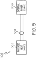
- the heating member 106 comprises a packaged heat source 502 and at least two leads 504, wherein the packaged heat source 502 is less than 3 mm in height with a planar area of less than 30 mm2.
- the heating member 106 includes a micro heater, a thick film heater, a resistive heating element, or any suitable heating member in any suitable combination.
- the heating member 106 may include a Micro Heater manufactured by Innovative Sensor Technology IST AG of Ebnat-Kappel, Switzerland or a suitable equivalent.
- the heating member 106 is configured to receive electrical power from an external power source 506.
- Figs. 1A , 2A-B , 3A , 4A , 5 , 6A-B , 7 and 16 by way of examples, the present disclosure is directed to a tacking stick 600 for tacking workpieces in composite manufacturing.
- Figs. 6A-B disclose an example of the tacking stick 600 that includes a support structure 120 and a plurality of tacking elements 100.
- Figs. 1A , 2A-B , 3A , 4A , 5 , 7 and 16 disclose various examples of the tacking stick 600.
- a tacking stick 600 for tacking workpieces in composite manufacturing includes a support structure 120 and a plurality of tacking elements 100 embedded in the support structure 120.
- the support structure 120 includes a contact surface 122 opposing a work surface 112 of a first workpiece 114 of a stack of workpieces 116.
- the contact surface 122 of the support structure 120 is configured to engage with the work surface 112 of the first workpiece 114.
- Each tacking element 100 extends through the contact surface 122 of the support structure 120.
- the support structure 120 may include a plurality of cavities configured to receive the plurality of tacking elements 100 to facilitate the embedding.
- each tacking element 100 includes a base member 102, an actuating member 104 and a heating member 106.
- the actuating member 104 is at least partially secured to the base member 102.
- the heating member 106 disposed on at least one of the base member 102 and the actuating member 104 and configured to selectively radiate heat toward the actuating member 104.
- the actuating member 104 is configured to transform from an inactive position 108 to an active position 110 in response to the heat from the heating member 106.
- the plurality of tacking elements 100 are configured to be disposed within the support structure 120 such that the active position 110 of the actuating member 104 of each tacking element 100 is proximate to a work surface 112 of a first workpiece 114 of a stack of workpieces 116.
- each tacking element 100 of the plurality of tacking elements 100 is configured to locally tack the first workpiece 114 to at least an adjacent workpiece 118 of the stack of workpieces 116 in response to at least one of the actuating member 104 and the heating member 106 being disposed proximate to the work surface 112 of the first workpiece 114 while the actuating member 104 is in the active position 110.
- a given workpiece e.g., first workpiece 114
- the stack of workpieces 116 may also be referred to as a stack of plies.
- a given ply may be referred to as a reinforcement fabric that includes carbon fibers and/or other types of suitable fibers.
- Thermoplastic and/or resin is included in the stack of workpieces 116 (e.g., stack of plies) using any suitable technique.
- a thermoplastic veil may be between adjacent plies or interleaved in the stack.
- a ply may refer to the combination of the dry fabric and an accompanying veil.
- thermoplastic particles may be integrated into the dry fabric in any suitable manner.
- the fabric may be pre-impregnated with resin which is referred to as pre-impregnated fabric or pre-preg.
- the tacking operation heats the thermoplastic and/or resin to tack two or more layers of the stack of workpieces 116.
- each tacking element 100 of the plurality of tacking elements 100 is configured to locally tack the first workpiece 114 to at least an adjacent workpiece 118 of the stack of workpieces 116 in response to at least one of the actuating member 104 and the heating member 106 of the corresponding tacking element 100 contacting the work surface 112 of the first workpiece 114 while the actuating member 104 of the corresponding tacking element 100 is in the active position 110.
- each tacking element 100 of the plurality of tacking elements 100 is configured to locally compress the stack of workpieces 116 in response to at least one of the actuating member 104 and the heating member 106 contacting the work surface 112 of the first workpiece 114 while the actuating member 104 is in the active position 110.
- the actuating member 104 may be constructed of material capable of applying up to approximately 75 kPa units of pressure to the work surface 112 of the first workpiece 114.
- each tacking element 100 of the plurality of tacking elements 100 is configured to locally compact the stack of workpieces 116 in response to at least one of the actuating member 104 and the heating member 106 contacting the work surface 112 of the first workpiece 114 while the actuating member 104 is in the active position 110.
- the actuating member 104 may be constructed of material capable of applying up to approximately 75 kPa units of pressure to the work surface 112 of the first workpiece 114.
- the plurality of tacking elements 100 are arranged in at least one of parallel rows and parallel columns. In still yet another example of the tacking stick 600, the plurality of tacking elements 100 are arranged in an array. In other examples, the plurality of tacking elements 100 may be distributed in any suitable arrangement.
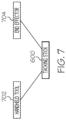
- the tacking stick 600 is configured to be secured to at least one of a handheld tool 702 and an end effector 704.
- the handheld tool 702 with the tacking stick 600 may be a single person lift or a multi-person lift depending on the weight of the items and applicable safety requirements.
- the tacking stick 60 may be secured to the end effector 704 by any suitable means.
- Figs. 1A , 2A-B , 3A , 4A , 5 , 6A-B . 7 , 8 and 16 by way of examples, the present disclosure is directed to a system 800 for tacking workpieces in composite manufacturing.
- Fig. 8 discloses an example of the system 800 that includes an end effector 704, a mechanical arm 802 and a computerized control system 804.
- the end effector 704 includes the tacking stick 600.
- Figs. 1A , 2A-B , 3A , 4A , 5 , 6A-B , 7 and 16 disclose various examples of the system 800.
- a system 800 for tacking workpieces in composite manufacturing includes an end effector 704, a mechanical arm 802 and a computerized control system 804.
- the end effector 704 includes the tacking stick 600 of Figs. 6A-B .
- the mechanical arm 802 configured to receive the end effector 704.
- the computerized control system 804 configured to control the mechanical arm 802, the end effector 704, the tacking stick 600, and each tacking element 100 of the plurality of tacking elements 100 to tack a first workpiece 114 to at least an adjacent workpiece 118 of a stack of workpieces 116 in response to at least one of the actuating member 104 and the heating member 106 of the corresponding tacking element 100 contacting the work surface 112 of the first workpiece 114 while the actuating member 104 of the corresponding tacking element 100 is in the active position 110.
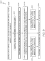
- Fig. 9 discloses an example of the method 900 that includes selectively heating 902 a heating member 106, transforming 904 an actuating member from an inactive position 108 to an active position 110, and locally tacking 906 a first workpiece 114 to at least an adjacent workpiece 118.
- Fig. 10 discloses various other examples of the method 900.
- a method 900 for tacking workpieces in composite manufacturing includes selectively heating 902 a heating member 106 of a tacking element 100.
- an actuating member 104 is transformed from an inactive position 108 to an active position 110.
- a first workpiece 114 of a stack of workpieces 116 is locally tacked to at least an adjacent workpiece 118 of the stack of workpieces 116 while the actuating member 104 is in the active position 110.
- a given workpiece e.g., first workpiece 114 may also be referred to as a ply.
- the stack of workpieces 116 may also be referred to as a stack of plies.
- a given ply may be referred to as a reinforcement fabric that includes carbon fibers and/or other types of suitable fibers.
- Thermoplastic and/or resin is included in the stack of workpieces 116 (e.g., stack of plies) using any suitable technique.
- a thermoplastic veil may be between adjacent plies or interleaved in the stack.
- a ply may refer to the combination of the dry fabric and an accompanying veil.
- thermoplastic particles may be integrated into the dry fabric in any suitable manner.
- the fabric may be pre-impregnated with resin which is referred to as pre-impregnated fabric or pre-preg.
- the tacking operation heats the thermoplastic and/or resin to tack two or more layers of the stack of workpieces 116.
- the actuating member 104 includes a shape memory alloy.
- the transforming 904 of the actuating member 104 to the active position 110 is in response to heat radiating from the heating member 106.
- the transforming 904 of the actuating member 104 to the active position 110 is in response to heat reaching a predetermined temperature.
- the predetermined temperature may range from 200° C to 280 ° C.
- the predetermined head may be up to 300 ° C.
- the active position 110 of the actuating member 104 is proximate to a work surface 112 of the first workpiece 114 of the stack of workpieces 116.
- the tacking element 100 is embedded in a support structure 120.
- the support structure 120 includes a contact surface 122.
- the tacking element 100 extends through the contact surface 122 of the support structure 120.
- the method 900 also includes engaging 908 the contact surface 122 of the support structure 120 with the work surface 112 of the first workpiece 114. The method 900 continues from 908 to 902.
- the tacking 906 is in response to at least one of the actuating member 104 and the heating member 106 being disposed proximate to the work surface 112 of the first workpiece 114. In yet another further example, the tacking 906 is in response to at least one of the actuating member 104 and the heating member 106 at least temporarily contacting the work surface 112 of the first workpiece 114.
- the support structure 120 may include a plurality of cavities configured to receive the plurality of tacking elements 100 to facilitate the embedding.
- the method 900 continues from 906 to 910 where the stack of workpieces 116 is locally compressed while the actuating member 104 is in the active position 110.
- the compressing 910 is in response to at least one of the actuating member 104 and the heating member 106 at least temporarily contacting a work surface 112 of the first workpiece 114 of the stack of workpieces 116.
- the actuating member 104 may be constructed of material capable of applying up to approximately 75 kPa units of pressure to the work surface 112 of the first workpiece 114.
- the method 900 continues from 906 to 912 where the stack of workpieces 116 is locally compacted while the actuating member 104 is in the active position 110.
- the compacting 912 is in response to at least one of the actuating member 104 and the heating member 106 at least temporarily contacting a work surface 112 of the first workpiece 114 of the stack of workpieces 116.
- the actuating member 104 may be constructed of material capable of applying up to approximately 75 kPa units of pressure to the work surface 112 of the first workpiece 114.
- the method 900 continues from 906 to 914 where the actuating member 104 is transformed from the active position 110 to the inactive position 108.
- the transforming 914 of Fig. 9 includes at least one of: (i) transforming 1002 the actuating member 104 using a biasing spring 202; (ii) transforming 1004 the actuating member 104 using a shape memory effect associated with the actuating member 104; (iii) transforming 1006 the actuating member 104 using a second actuating member 204 with shape memory; and (iv) transforming 1008 the actuating member 104 using an insert 302 and a compression technique.
- An example of the shape memory effect associated with the actuating member 104 is where the actuating member 104 includes a shape memory alloy capable of being trained to exhibit multiple shape memory effects.
- a first shape memory effect is triggered by the heating member 106 and transforms the actuating member 104 from an inactive position to an active position for the tacking operation.
- a second shape memory effect is triggered by a lower temperature that transforms the actuating member 104 from the active position to the inactive position after the tacking operation.
- a second actuating member 204 with shape memory is a second actuating member 204 that includes a shape memory alloy that is trained to be triggered to apply a force that transforms the actuating member 204 from the active position to the inactive position at a predetermined temperature.
- the tacking element 100 may include additional components, such as a second heating member, to radiate heat that triggers the second actuating member 204.
- the drawing provides perspective views of examples of plies of dry fabric before and after tacking.
- the left view shows an example of a stack of plies of dry fabric before the tacking operation.
- the stack may include two or more plies.
- the stack depth may be approximately 1.5 mm.
- Thermoplastic is included in the stack using any suitable technique.
- a thermoplastic veil may be between adjacent plies or interleaved in the stack.
- a given ply may be referred to as a reinforcement fabric that includes carbon fibers and/or other types of suitable fibers.
- Thermoplastic and/or resin is included in the stack of plies using any suitable technique.
- thermoplastic veil may be between adjacent plies or interleaved in the stack.
- a ply may refer to the combination of the dry fabric and an accompanying veil.
- thermoplastic particles may be integrated into the dry fabric in any suitable manner.
- the fabric may be pre-impregnated with resin in which the fabric is then referred to as pre-impregnated fabric or pre-preg.
- the tacking operation heats the thermoplastic and/or resin to tack two or more layers of the stack.
- the right view shows an example of the top two plies tacked together after the tacking operation.
- a tacking element 100 for tacking workpieces in composite manufacturing includes a base member 102, an actuating member 104, and a heating member 106.
- the base member 102 may be at least partially bonded onto to membrane of a tacking stick 600.
- the heating member 106 may be disposed on a surface of the actuating member 104 (as shown). Alternatively, the heating member 106 may be disposed on an opposite surface of the actuating member 104 (not shown).
- the tacking element 100 has a circular footprint. In this example, the diameter for the footprint may be approximately 20 mm and may range from approximately 10 mm to approximately 35 mm.
- the heating member 106 is encapsulated in a square package.
- the package dimensions may be approximately 5 mm 2 . In other examples, the package dimensions may be approximately 10 mm 2 , approximately 15 mm 2 or any suitable dimensions.
- the drawing provides the perspective view of the tacking element 100 of Fig. 12A , a detailed top view of the heating member 106 and a portion of the actuating member and a cross-sectional view.
- the cross-section view shows the heating member 106 disposed on a surface of the actuating member 104 and an optional thermal conductive layer 1302 over a contact surface 1304 of the heating member 106.
- the contact surface 1304 of the heating member 106 is the portion of the tacking element 100 that proximates and/or contacts the work surface 112 of the first workpiece 114 of the stack of workpieces 116.
- the thermal conductive layer 1302 may include any suitable coating that permits suitable heat transfer and prevents residue from being deposited on the heating member 106 due to the tacking operation.
- the heating member 106 may be disposed on an opposite surface of the actuating member 104.
- the contact surface 1304 is a raised portion of the actuating element.
- the thermal conductive layer 1302 may be used to coat the contact surface 1304 of the actuating member 104, additional portions surrounding the contact surface 1304 and/or the entire surface of the actuating member.
- the tacking element 100 includes a base member 102, an actuating member 104, and a heating member 106.
- the base member 102 has a circular footprint.
- the diameter for the footprint for the base member 102 may be approximately 20 mm.
- the actuating member 104 is shown in a spiral, spring-like shape that moves from an inactive position (not shown) at low temperature (e.g., room temperature) to an active position (as shown) at high temperature (e.g., greater than 120° C).
- the actuating member 104 having a proximal end secured to the base member 102 and a distal end to which the heating member 106 is secured. As shown, the heating member 106 also has a circular footprint. In this example, the diameter for the footprint for the heating member 106 may be approximately 5 mm.
- the heating member 106 includes a contact surface 1304 that, in the active position (as shown), proximates and/or contacts the work surface 112 of the first workpiece 114 of the stack of workpieces 116.
- the drawing provides a partial top view of another example of a tacking stick 600 for tacking workpieces in composite manufacturing and several detailed side views of another example of a tacking element 100 in the tacking stick 600.
- the partial top view shows a portion of the tacking stick 600 with nine tacking elements 100 arranged in an array.
- the detailed side views show the actuating member 104 and the heating member 106 of a typical tacking element 100 for this tacking stick 600.
- the actuating member 104 is shown at room temperature in the inactive position and at high temperature (e.g., greater than 120° C) in the active position.
- the actuating member 104 includes a shape memory alloy and the heating member 106 may include a Micro Heater manufactured by Innovative Sensor Technology IST AG of Ebnat-Kappel, Switzerland or a suitable equivalent.
- the drawing provides a partial top view of yet another example of a tacking stick 600 for tacking workpieces in composite manufacturing.
- the partial top view shows a portion of the tacking stick 600 with twelve tacking elements 100 arranged in rows. Alternating rows are offset by half the distance between adjacent tacking elements 100 in the preceding and succeeding rows. This creates alternating diamond and X-shapes for groups of four tacking elements 100 as one moves horizontally across three consecutive rows.
- Examples of the tacking element 100, tacking stick 600, system 800, and method 900 may be related to, or used in the context of tacking workpieces (e.g., dry fabrics) for thermoplastic composite parts used in aircraft manufacturing.
- tacking workpieces e.g., dry fabrics
- the examples and principles disclosed herein may be applied to other products in the aerospace industry and other industries, such as the automotive industry, the space industry, the construction industry, and other design and manufacturing industries. Accordingly, in addition to aircraft, the examples and principles disclosed herein may apply to stamp forming workpieces to form an assembly for other types of vehicles (e.g., land vehicles, marine vehicles, space vehicles, etc.), stand-alone structures, high-traffic surfaces, and other high-contact surfaces.
- vehicles e.g., land vehicles, marine vehicles, space vehicles, etc.
- stand-alone structures e.g., high-traffic surfaces, and other high-contact surfaces.
- example means that one or more feature, structure, element, component, characteristic, and/or operational step described in connection with the example is included in at least one aspect, embodiment, and/or implementation of the subject matter according to the present disclosure.
- the phrases “an example,” “another example,” “one or more examples,” and similar language throughout the present disclosure may, but do not necessarily, refer to the same example.
- the subject matter characterizing any one example may, but does not necessarily, include the subject matter characterizing any other example.
- subject matter characterizing any one example may be, but is not necessarily, combined with the subject matter characterizing any other example.
- a system, apparatus, device, structure, article, element, component, or hardware "configured to” perform a specified function is indeed capable of performing the specified function without any alteration, rather than merely having potential to perform the specified function after further modification.
- the system, apparatus, device, structure, article, element, component, or hardware "configured to” perform a specified function is specifically selected, created, implemented, utilized, programmed, and/or designed for the purpose of performing the specified function.
- "configured to” denotes existing characteristics of a system, apparatus, structure, article, element, component, or hardware that enable the system, apparatus, structure, article, element, component, or hardware to perform the specified function without further modification.
- a system, apparatus, device, structure, article, element, component, or hardware described as being “configured to” perform a particular function may additionally or alternatively be described as being “adapted to” and/or as being “operative to” perform that function.
- first,” “second,” “third,” etc. are used herein merely as labels, and are not intended to impose ordinal, positional, or hierarchical requirements on the items to which these terms refer. Moreover, reference to, e.g., a “second” item does not require or preclude the existence of, e.g., a "first” or lower-numbered item, and/or, e.g., a "third” or higher-numbered item.
- the phrase "at least one of,” when used with a list of items, means different combinations of one or more of the listed items may be used and only one of each item in the list may be needed.
- “at least one of item A, item B, and item C” may include, without limitation, item A or item A and item B. This example also may include item A, item B, and item C, or item B and item C.
- "at least one of” may be, for example, without limitation, two of item A, one of item B, and ten of item C; four of item B and seven of item C; and other suitable combinations.
- the term “and/or” and the "/" symbol includes any and all combinations of one or more of the associated listed items.
- Coupled refers to two or more elements that are joined, linked, fastened, attached, connected, put in communication, or otherwise associated (e.g., mechanically, electrically, fluidly, optically, electromagnetically) with one another.
- the elements may be associated directly or indirectly.
- element A may be directly associated with element B.
- element A may be indirectly associated with element B, for example, via another element C. It will be understood that not all associations among the various disclosed elements are necessarily represented. Accordingly, couplings other than those depicted in the figures may also exist.
- the term “approximately” refers to or represents a condition that is close to, but not exactly, the stated condition that still performs the desired function or achieves the desired result.
- the term “approximately” refers to a condition that is within an acceptable predetermined tolerance or accuracy, such as to a condition that is within 10% of the stated condition.
- the term “approximately” does not exclude a condition that is exactly the stated condition.
- the term “substantially” refers to a condition that is essentially the stated condition that performs the desired function or achieves the desired result.
- references throughout the present specification to features, advantages, or similar language used herein do not imply that all the features and advantages that may be realized with the examples disclosed herein should be, or are in, any single example. Rather, language referring to the features and advantages is understood to mean that a specific feature, advantage, or characteristic described in connection with an example is included in at least one example. Thus, discussion of features, advantages, and similar language used throughout the present disclosure may, but does not necessarily, refer to the same example.
- the disclosed methods and systems for associating test data for a part under test with an end item coordinate system may be used in aircraft manufacturing.
- the service method 1700 may include specification and design (block 1702) of aircraft 1800 and material procurement (block 1704).
- component and subassembly manufacturing (block 1706) and system integration (block 1708) of aircraft 1800 may take place.
- aircraft 1800 may go through certification and delivery (block 1710) to be placed in service (block 1712).
- aircraft 1800 may be scheduled for routine maintenance and service (block 1714). Routine maintenance and service may include modification, reconfiguration, refurbishment, etc. of one or more systems of aircraft 1800.
- Each of the processes of the service method 1700 may be performed or carried out by a system integrator, a third party, and/or an operator (e.g., a customer).
- a system integrator may include, without limitation, any number of aircraft manufacturers and major-system subcontractors
- a third party may include, without limitation, any number of vendors, subcontractors, and suppliers
- an operator may be an airline, leasing company, military entity, service organization, and so on.
- aircraft 1800 produced by the service method 1700 may include airframe 1802 with a plurality of high-level systems 1804 and interior 1806.
- high-level systems 1804 include one or more of propulsion system 1808, electrical system 1810, hydraulic system 1812, and environmental system 1814. Any number of other systems may be included.
- propulsion system 1808 the principles disclosed herein may be applied to other industries, such as the automotive industry. Accordingly, in addition to aircraft 1800, the principles disclosed herein may apply to other vehicles, e.g., land vehicles, marine vehicles, space vehicles, etc.
- the disclosed systems and methods for associating test data for a part under test with an end item coordinate system may be employed during any one or more of the stages of the manufacturing and service method 1700.
- components or subassemblies corresponding to component and subassembly manufacturing (block 1706) may be fabricated or manufactured in a manner similar to components or subassemblies produced while aircraft 1800 is in service (block 1712).
- one or more examples of the system(s), method(s), or combination thereof may be utilized during production stages (block 1706 and block 1708), for example, by substantially expediting assembly of or reducing the cost of aircraft 1800.
- one or more examples of the system or method realizations, or a combination thereof may be utilized, for example and without limitation, while aircraft 1800 is in service (block 1712) and/or during maintenance and service (block 1714).
Landscapes
- Engineering & Computer Science (AREA)
- Mechanical Engineering (AREA)
- Chemical & Material Sciences (AREA)
- Combustion & Propulsion (AREA)
- General Engineering & Computer Science (AREA)
- Physics & Mathematics (AREA)
- Thermal Sciences (AREA)
- Manufacturing & Machinery (AREA)
- Transportation (AREA)
- Aviation & Aerospace Engineering (AREA)
- Control Of Resistance Heating (AREA)
- Lining Or Joining Of Plastics Or The Like (AREA)
Abstract
Description
- The present disclosure relates generally to tacking workpieces in composite manufacturing and, particularly, to various examples of tacking elements, tacking sticks, and systems for tacking workpieces in composite manufacturing. Various examples of methods for tacking workpieces in composite manufacturing are also disclosed. For example, applications of tacking workpieces can be used to tack plies of dry reinforcement fabric for composite materials used in aircraft. Applications to other types of workpieces, various types of composite materials, and other types of products are also contemplated.
- Manual and automated tacking approaches are used in producing composite parts from dry fabrics. The manual approach relies on an operator with a soldering iron to perform tacking of adjacent plies of dry fabric. The automated approach uses cartridge style heating elements to perform localized tacking of the adjacent plies. The cartridge style heating elements are long and difficult to integrate into automated production methods. Another drawback of cartridge style heating elements is that cooling is slow which requires removal of the heating surface from the material after a few seconds. Moreover, the heating element may be left on during tacking operations due to the slow heating and cooling of the cartridge style heating element. This is not an efficient use of energy.
- Accordingly, those skilled in the art continue with research and development efforts to streamline tacking operations for composite manufacturing to improve automated production methods.
- Disclosed are examples of apparatuses, tacking sticks, and systems for tacking workpieces in composite manufacturing. Examples of methods for tacking workpieces in composite manufacturing are also disclosed. The following is a non-exhaustive list of examples, which may or may not be claimed, of the subject matter according to the present disclosure.
- In an example, the disclosed apparatus for tacking workpieces in composite manufacturing includes a base member, an actuating member and a heating member. The actuating member is at least partially secured to the base member. The heating member disposed on at least one of the base member and the actuating member and configured to selectively radiate heat toward the actuating member. The actuating member is configured to transform from an inactive position to an active position in response to the heat from the heating member.
- In an example, the disclosed tacking stick for tacking workpieces in composite manufacturing includes a support structure and a plurality of tacking elements embedded in the support structure. The support structure includes comprising a contact surface opposing a work surface of a first workpiece of a stack of workpieces. The contact surface of the support structure is configured to engage with the work surface of the first workpiece. Each tacking element extends through the contact surface of the support structure.
- In an example, the disclosed method for tacking workpieces in composite manufacturing includes: (1) selectively heating a heating member of a tacking element; (2) transforming an actuating member from an inactive position to an active position; and (3) locally tacking a first workpiece of a stack of workpieces to at least an adjacent workpiece of the stack of workpieces while the actuating member is in the active position.
- In an example, the disclosed system for tacking workpieces in composite manufacturing includes an end effector, a mechanical arm and a computerized control system. The end effector includes a tacking stick. The tacking stick includes a support structure and a plurality of tacking elements. The support structure includes a contact surface. The plurality of tacking elements are embedded in the support structure and extend through the contact surface of the support structure. Each tacking element includes a base member, an actuating member with shape memory, and a heating member. The actuating member is at least partially secured to the base member. The heating member disposed on at least one of the base member and the actuating member. The mechanical arm configured to receive the end effector. The computerized control system is configured to control the mechanical arm, the end effector, the tacking stick, and the plurality of tacking elements by implementing a method for tacking workpieces in composite manufacturing. The method includes: (1) selectively heating the heating member of a select tacking element; (2) transforming the actuating member of the select tacking element from an inactive position to an active position; and (3) locally tacking a first workpiece of a stack of workpieces to at least an adjacent workpiece of the stack of workpieces while the actuating member of the select tacking element is in the active position.
- Other examples of the disclosed methods and systems will become apparent from the following detailed description, the accompanying drawings, and the appended claims.
-
-
Figs. 1A-D provide a functional exploded view of an example of a tacking element for tacking workpieces in composite manufacturing, and several cross-sectional views; -
Figs. 2A-D provide partial side views of several examples of transitioning the actuating member of the tacking element ofFig. 1D from an active position to an inactive position; -
Figs. 3A-B provide partial side views of another example of transitioning the actuating member of the tacking element ofFig. 1D from an active position to an inactive position; -
Figs. 4A-D include a functional exploded side view of another example of a tacking element for tacking workpieces in composite manufacturing and partial side views of several other examples of the tacking element; -
Fig. 5 is a functional block diagram of an example of a heating element of the tacking element inFig. 1A ; -
Figs. 6A-B include a functional exploded side view of an example of a tacking stick for tacking workpieces in composite manufacturing and a cross-sectional view; -
Fig. 7 is a functional block diagram showing several examples of techniques for using the tacking stick ofFigs. 6A-B ; -
Fig. 8 is a functional block diagram of an example of a system for tacking workpieces in composite manufacturing; -
Fig. 9 is a flow diagram of an example of a method for tacking workpieces in composite manufacturing; -
Fig. 10 , in combination withFig. 9 , is a flow diagram showing several examples for the transforming of the actuating member from the active position to the inactive position inFig. 9 ; -
Figs. 11A-B provide perspective views of examples of plies of dry fabric before and after tacking; -
Figs. 12A-B provides a perspective view of another example of a tacking element for tacking workpieces in composite manufacturing and a top view; -
Figs. 13A-C provide the perspective view ofFig. 12A , a detailed top view of the heating member and a cross-sectional view; -
Fig. 14 provides a top schematic view of yet another example of a tacking element for tacking workpieces in composite manufacturing and a cross-sectional view; -
Figs. 15A-B provide a partial top view of another example of a tacking stick for tacking workpieces in composite manufacturing and several detailed side views of another example of a tacking element in the tacking stick; and -
Fig. 16 provides a partial top view of yet another example of a tacking stick for tacking workpieces in composite manufacturing. -
Fig. 17 is a block diagram of aircraft production and service methodology; and -
Fig. 18 is a schematic illustration of an aircraft. - Referring generally to
Figs. 1A-D ,2A-D ,3A-B ,4A-D ,5 and12-15 , by way of examples, the present disclosure is directed to a tackingelement 100 for tacking workpieces in composite manufacturing.Fig. 1A discloses an example of the tackingelement 100 that includes abase member 102, an actuatingmember 104 and aheating member 106.Figs. 2A-D ,3A-B ,4A-D ,5 and12-15 disclose various examples of the tackingelement 100. - With reference again to
Figs. 1A-D , in one or more examples, a tackingelement 100 for tacking workpieces in composite manufacturing includes abase member 102, an actuatingmember 104 at least partially secured to thebase member 102, and aheating member 106 disposed on at least one of thebase member 102 and the actuatingmember 104. The heating member configured to selectively radiate heat toward the actuatingmember 104. The actuatingmember 104 is configured to transform from aninactive position 108 to anactive position 110 in response to the heat from theheating member 106. - In another example of the tacking
element 100, the actuatingmember 104 includes a shape memory alloy. In a further example, the shape memory alloy includes aluminium (Al), cadmium (Cd), copper (Cu), gold (Au), iron (Fe), manganese (Mn), nickel (Ni), silicon (Si), titanium (Ti), zinc (Zn) or any suitable material with shape memory in any suitable combination. In another further example, the shape memory alloy includes nickel-titanium (Ni-Ti), copper-aluminum-nickel (Cu-Al-Ni), copper-zinc-aluminum (Cu-Zn-Al), iron-manganese-silicon (Fe-Mn-Si), gold-cadmium (Au-Cd), or any suitable shape memory alloy. - In yet another example of the tacking
element 100, the actuatingmember 104 is configured to transform to theactive position 110 in response to the heat reaching a predetermined temperature. For example, the predetermined temperature may range from 200° C to 280 ° C. In another example, the predetermined head may be up to 300 ° C. - In still another example, the tacking
element 100 is configured to be disposed such that theactive position 110 of the actuatingmember 104 is proximate to awork surface 112 of afirst workpiece 114 of a stack ofworkpieces 116. - In a further example, the tacking
element 100 is configured to be embedded in asupport structure 120 with acontact surface 122. In this example, the tackingelement 100 is configured to extend through thecontact surface 122 of thesupport structure 120. In an even further example, thecontact surface 122 of thesupport structure 120 opposes thework surface 112 of thefirst workpiece 114. In this example, thecontact surface 122 is configured to engage with thework surface 112. For example, thesupport structure 120 may include a plurality of cavities configured to receive the plurality of tackingelements 100 to facilitate the embedding. - In another further example, the tacking
element 100 is configured to locally tack thefirst workpiece 114 to at least anadjacent workpiece 118 of the stack ofworkpieces 116 in response to at least one of the actuatingmember 104 and theheating member 106 being disposed proximate to thework surface 112 of thefirst workpiece 114 while the actuatingmember 104 is in theactive position 110. For example, a given workpiece (e.g., first workpiece 114) may also be referred to as a ply. In this example, the stack ofworkpieces 116 may also be referred to as a stack of plies. In various examples, a given ply may be referred to as a reinforcement fabric that includes carbon fibers and/or other types of suitable fibers. Thermoplastic and/or resin is included in the stack of workpieces 116 (e.g., stack of plies) using any suitable technique. For example, a thermoplastic veil may be between adjacent plies or interleaved in the stack. In some examples, a ply may refer to the combination of the dry fabric and an accompanying veil. Alternatively, thermoplastic particles may be integrated into the dry fabric in any suitable manner. For example, the fabric may be pre-impregnated with resin which is referred to as pre-impregnated fabric or pre-preg. In any regard, the tacking operation heats the thermoplastic and/or resin to tack two or more layers of the stack ofworkpieces 116. - In yet another further example, the tacking
element 100 is configured to locally tack thefirst workpiece 114 to at least anadjacent workpiece 118 of the stack ofworkpieces 116 in response to at least one of the actuatingmember 104 and theheating member 106 contacting thework surface 112 of thefirst workpiece 114 while the actuating member 104is in theactive position 110. - It still another further example, the tacking
element 100 is configured to locally compress the stack ofworkpieces 116 in response to at least one of the actuatingmember 104 and theheating member 106 contacting thework surface 112 of thefirst workpiece 114 while the actuatingmember 104 is in theactive position 110. For example, in the active position, the actuatingmember 104 may be constructed of material capable of applying up to approximately 75 Kilopascal (kPa) units of pressure to thework surface 112 of thefirst workpiece 114. - In still yet another further example, the tacking
element 100 is configured to locally compact the stack ofworkpieces 116 in response to at least one of the actuatingmember 104 and theheating member 106 contacting thework surface 112 of thefirst workpiece 114 while the actuatingmember 104 is in theactive position 110. For example, in the active position, the actuatingmember 104 may be constructed of material capable of applying up to approximately 75 kPa units of pressure to thework surface 112 of thefirst workpiece 114. - With reference again to
Figs. 1A ,2A-B and3A-B , in still yet another example, the tackingelement 100 is configured to transform the actuatingmember 104 from theactive position 110 to theinactive position 108 using at least one of abiasing spring 202, a shape memory effect associated with the actuatingmember 104, asecond actuating member 204 with shape memory, and aninsert 302 fitted for compression of the actuatingmember 104 in any suitable combination. - An example of the shape memory effect associated with the actuating
member 104 is where the actuatingmember 104 includes a shape memory alloy capable of being trained to exhibit multiple shape memory effects. A first shape memory effect is triggered by theheating member 106 and transforms the actuatingmember 104 from an inactive position to an active position for the tacking operation. A second shape memory effect is triggered by a lower temperature that transforms the actuatingmember 104 from the active position to the inactive position after the tacking operation. - An example of a
second actuating member 204 with shape memory is asecond actuating member 204 that includes a shape memory alloy that is trained to be triggered to apply a force that transforms the actuatingmember 204 from the active position to the inactive position at a predetermined temperature. The tackingelement 100 may include additional components, such as a second heating member, to radiate heat that triggers thesecond actuating member 204. - In another example of the tacking
element 100, thebase member 102 includes an insulating material. - With reference again to
Figs. 1A and4A-D , in yet another example of the tackingelement 100, the actuatingmember 104 includes afirst surface 402 facing thebase member 102 and asecond surface 404 configured to face awork surface 112 of afirst workpiece 114 of a stack ofworkpieces 116. In a further example, theheating member 106 is secured to thefirst surface 402 of the actuatingmember 104. In another further example, theheating member 106 is secured to thesecond surface 404 of the actuatingmember 104. In still another example of the tackingelement 100, theheating member 106 is embedded within the actuatingmember 104. For example, thesupport structure 120 may include a plurality of cavities configured to receive the plurality of tackingelements 100 to facilitate the embedding. - With reference again to
Figs. 1A and5 , in still yet another example of the tackingelement 100, theheating member 106 comprises a packagedheat source 502 and at least twoleads 504, wherein the packagedheat source 502 is less than 3 mm in height with a planar area of less than 30 mm2. In another example of the tackingelement 100, theheating member 106 includes a micro heater, a thick film heater, a resistive heating element, or any suitable heating member in any suitable combination. For example, theheating member 106 may include a Micro Heater manufactured by Innovative Sensor Technology IST AG of Ebnat-Kappel, Switzerland or a suitable equivalent. In yet another example of the tackingelement 100, theheating member 106 is configured to receive electrical power from anexternal power source 506. - Referring generally to
Figs. 1A ,2A-B ,3A ,4A ,5 ,6A-B ,7 and16 , by way of examples, the present disclosure is directed to a tackingstick 600 for tacking workpieces in composite manufacturing.Figs. 6A-B disclose an example of the tackingstick 600 that includes asupport structure 120 and a plurality of tackingelements 100.Figs. 1A ,2A-B ,3A ,4A ,5 ,7 and16 disclose various examples of the tackingstick 600. - With reference again to
Figs. 1A and6A-B , in one or more examples, a tackingstick 600 for tacking workpieces in composite manufacturing includes asupport structure 120 and a plurality of tackingelements 100 embedded in thesupport structure 120. Thesupport structure 120 includes acontact surface 122 opposing awork surface 112 of afirst workpiece 114 of a stack ofworkpieces 116. Thecontact surface 122 of thesupport structure 120 is configured to engage with thework surface 112 of thefirst workpiece 114. Each tackingelement 100 extends through thecontact surface 122 of thesupport structure 120. For example, thesupport structure 120 may include a plurality of cavities configured to receive the plurality of tackingelements 100 to facilitate the embedding. - In another example of the tacking
stick 600, each tackingelement 100 includes abase member 102, an actuatingmember 104 and aheating member 106. The actuatingmember 104 is at least partially secured to thebase member 102. Theheating member 106 disposed on at least one of thebase member 102 and the actuatingmember 104 and configured to selectively radiate heat toward the actuatingmember 104. The actuatingmember 104 is configured to transform from aninactive position 108 to anactive position 110 in response to the heat from theheating member 106. - In yet another example of the tacking
stick 600, the plurality of tackingelements 100 are configured to be disposed within thesupport structure 120 such that theactive position 110 of the actuatingmember 104 of each tackingelement 100 is proximate to awork surface 112 of afirst workpiece 114 of a stack ofworkpieces 116. - In a further example, each tacking
element 100 of the plurality of tackingelements 100 is configured to locally tack thefirst workpiece 114 to at least anadjacent workpiece 118 of the stack ofworkpieces 116 in response to at least one of the actuatingmember 104 and theheating member 106 being disposed proximate to thework surface 112 of thefirst workpiece 114 while the actuatingmember 104 is in theactive position 110. For example, a given workpiece (e.g., first workpiece 114) may also be referred to as a ply. In this example, the stack ofworkpieces 116 may also be referred to as a stack of plies. In various examples, a given ply may be referred to as a reinforcement fabric that includes carbon fibers and/or other types of suitable fibers. Thermoplastic and/or resin is included in the stack of workpieces 116 (e.g., stack of plies) using any suitable technique. For example, a thermoplastic veil may be between adjacent plies or interleaved in the stack. In some examples, a ply may refer to the combination of the dry fabric and an accompanying veil. Alternatively, thermoplastic particles may be integrated into the dry fabric in any suitable manner. For example, the fabric may be pre-impregnated with resin which is referred to as pre-impregnated fabric or pre-preg. In any regard, the tacking operation heats the thermoplastic and/or resin to tack two or more layers of the stack ofworkpieces 116. - In another further example, each tacking
element 100 of the plurality of tackingelements 100 is configured to locally tack thefirst workpiece 114 to at least anadjacent workpiece 118 of the stack ofworkpieces 116 in response to at least one of the actuatingmember 104 and theheating member 106 of the corresponding tackingelement 100 contacting thework surface 112 of thefirst workpiece 114 while the actuatingmember 104 of the corresponding tackingelement 100 is in theactive position 110. - In yet another further example, each tacking
element 100 of the plurality of tackingelements 100 is configured to locally compress the stack ofworkpieces 116 in response to at least one of the actuatingmember 104 and theheating member 106 contacting thework surface 112 of thefirst workpiece 114 while the actuatingmember 104 is in theactive position 110. For example, in the active position, the actuatingmember 104 may be constructed of material capable of applying up to approximately 75 kPa units of pressure to thework surface 112 of thefirst workpiece 114. - In still another further example, each tacking
element 100 of the plurality of tackingelements 100 is configured to locally compact the stack ofworkpieces 116 in response to at least one of the actuatingmember 104 and theheating member 106 contacting thework surface 112 of thefirst workpiece 114 while the actuatingmember 104 is in theactive position 110. For example, in the active position, the actuatingmember 104 may be constructed of material capable of applying up to approximately 75 kPa units of pressure to thework surface 112 of thefirst workpiece 114. - In still another example of the tacking
stick 600, the plurality of tackingelements 100 are arranged in at least one of parallel rows and parallel columns. In still yet another example of the tackingstick 600, the plurality of tackingelements 100 are arranged in an array. In other examples, the plurality of tackingelements 100 may be distributed in any suitable arrangement. - With reference again to
Figs. 6A-B and7 , in one or more examples, the tackingstick 600, is configured to be secured to at least one of ahandheld tool 702 and anend effector 704. Thehandheld tool 702 with the tackingstick 600 may be a single person lift or a multi-person lift depending on the weight of the items and applicable safety requirements. The tacking stick 60 may be secured to theend effector 704 by any suitable means. - Referring generally to
Figs. 1A ,2A-B ,3A ,4A ,5 ,6A-B .7 ,8 and16 , by way of examples, the present disclosure is directed to asystem 800 for tacking workpieces in composite manufacturing.Fig. 8 discloses an example of thesystem 800 that includes anend effector 704, amechanical arm 802 and acomputerized control system 804. Theend effector 704 includes the tackingstick 600.Figs. 1A ,2A-B ,3A ,4A ,5 ,6A-B ,7 and16 disclose various examples of thesystem 800. - With reference again to
Figs. 1A ,6A-B ,7 and8 , in one or more examples, asystem 800 for tacking workpieces in composite manufacturing includes anend effector 704, amechanical arm 802 and acomputerized control system 804. Theend effector 704 includes the tackingstick 600 ofFigs. 6A-B . Themechanical arm 802 configured to receive theend effector 704. Thecomputerized control system 804 configured to control themechanical arm 802, theend effector 704, the tackingstick 600, and each tackingelement 100 of the plurality of tackingelements 100 to tack afirst workpiece 114 to at least anadjacent workpiece 118 of a stack ofworkpieces 116 in response to at least one of the actuatingmember 104 and theheating member 106 of the corresponding tackingelement 100 contacting thework surface 112 of thefirst workpiece 114 while the actuatingmember 104 of the corresponding tackingelement 100 is in theactive position 110. - Referring generally to
Figs. 1A ,9 and10 , by way of examples, the present disclosure is directed to amethod 900 for tacking workpieces in composite manufacturing.Fig. 9 discloses an example of themethod 900 that includes selectively heating 902 aheating member 106, transforming 904 an actuating member from aninactive position 108 to anactive position 110, and locally tacking 906 afirst workpiece 114 to at least anadjacent workpiece 118.Fig. 10 discloses various other examples of themethod 900. - With reference again to
Figs. 1A and9 , in one or more examples, amethod 900 for tacking workpieces in composite manufacturing includes selectively heating 902 aheating member 106 of a tackingelement 100. At 904, an actuatingmember 104 is transformed from aninactive position 108 to anactive position 110. At 906, afirst workpiece 114 of a stack ofworkpieces 116 is locally tacked to at least anadjacent workpiece 118 of the stack ofworkpieces 116 while the actuatingmember 104 is in theactive position 110. For example, a given workpiece (e.g., first workpiece 114) may also be referred to as a ply. In this example, the stack ofworkpieces 116 may also be referred to as a stack of plies. In various examples, a given ply may be referred to as a reinforcement fabric that includes carbon fibers and/or other types of suitable fibers. Thermoplastic and/or resin is included in the stack of workpieces 116 (e.g., stack of plies) using any suitable technique. For example, a thermoplastic veil may be between adjacent plies or interleaved in the stack. In some examples, a ply may refer to the combination of the dry fabric and an accompanying veil. Alternatively, thermoplastic particles may be integrated into the dry fabric in any suitable manner. For example, the fabric may be pre-impregnated with resin which is referred to as pre-impregnated fabric or pre-preg. In any regard, the tacking operation heats the thermoplastic and/or resin to tack two or more layers of the stack ofworkpieces 116. - In another example of the
method 900, the actuatingmember 104 includes a shape memory alloy. In yet another example of themethod 900, the transforming 904 of the actuatingmember 104 to theactive position 110 is in response to heat radiating from theheating member 106. In still another example of themethod 900, the transforming 904 of the actuatingmember 104 to theactive position 110 is in response to heat reaching a predetermined temperature. For example, the predetermined temperature may range from 200° C to 280 ° C. In another example, the predetermined head may be up to 300 ° C. - In still yet another example of the
method 900, in conjunction with the transforming 904 and the tacking 906, theactive position 110 of the actuatingmember 104 is proximate to awork surface 112 of thefirst workpiece 114 of the stack ofworkpieces 116. In a further example, the tackingelement 100 is embedded in asupport structure 120. Thesupport structure 120 includes acontact surface 122. The tackingelement 100 extends through thecontact surface 122 of thesupport structure 120. In an even further example, themethod 900 also includes engaging 908 thecontact surface 122 of thesupport structure 120 with thework surface 112 of thefirst workpiece 114. Themethod 900 continues from 908 to 902. In another further example, the tacking 906 is in response to at least one of the actuatingmember 104 and theheating member 106 being disposed proximate to thework surface 112 of thefirst workpiece 114. In yet another further example, the tacking 906 is in response to at least one of the actuatingmember 104 and theheating member 106 at least temporarily contacting thework surface 112 of thefirst workpiece 114. For example, thesupport structure 120 may include a plurality of cavities configured to receive the plurality of tackingelements 100 to facilitate the embedding. - In another example, the
method 900 continues from 906 to 910 where the stack ofworkpieces 116 is locally compressed while the actuatingmember 104 is in theactive position 110. In a further example, the compressing 910 is in response to at least one of the actuatingmember 104 and theheating member 106 at least temporarily contacting awork surface 112 of thefirst workpiece 114 of the stack ofworkpieces 116. For example, in the active position, the actuatingmember 104 may be constructed of material capable of applying up to approximately 75 kPa units of pressure to thework surface 112 of thefirst workpiece 114. - In yet another example, the
method 900 continues from 906 to 912 where the stack ofworkpieces 116 is locally compacted while the actuatingmember 104 is in theactive position 110. In a further example, the compacting 912 is in response to at least one of the actuatingmember 104 and theheating member 106 at least temporarily contacting awork surface 112 of thefirst workpiece 114 of the stack ofworkpieces 116. For example, in the active position, the actuatingmember 104 may be constructed of material capable of applying up to approximately 75 kPa units of pressure to thework surface 112 of thefirst workpiece 114. - In still another example, the
method 900 continues from 906 to 914 where the actuatingmember 104 is transformed from theactive position 110 to theinactive position 108. - With reference again to
Figs. 1A ,9 and10 in one or more examples, the transforming 914 ofFig. 9 includes at least one of: (i) transforming 1002 the actuatingmember 104 using abiasing spring 202; (ii) transforming 1004 the actuatingmember 104 using a shape memory effect associated with the actuatingmember 104; (iii) transforming 1006 the actuatingmember 104 using asecond actuating member 204 with shape memory; and (iv) transforming 1008 the actuatingmember 104 using aninsert 302 and a compression technique. - An example of the shape memory effect associated with the actuating
member 104 is where the actuatingmember 104 includes a shape memory alloy capable of being trained to exhibit multiple shape memory effects. A first shape memory effect is triggered by theheating member 106 and transforms the actuatingmember 104 from an inactive position to an active position for the tacking operation. A second shape memory effect is triggered by a lower temperature that transforms the actuatingmember 104 from the active position to the inactive position after the tacking operation. - An example of a
second actuating member 204 with shape memory is asecond actuating member 204 that includes a shape memory alloy that is trained to be triggered to apply a force that transforms the actuatingmember 204 from the active position to the inactive position at a predetermined temperature. The tackingelement 100 may include additional components, such as a second heating member, to radiate heat that triggers thesecond actuating member 204. - With reference again to
Figs. 11A-B , the drawing provides perspective views of examples of plies of dry fabric before and after tacking. The left view shows an example of a stack of plies of dry fabric before the tacking operation. The stack may include two or more plies. For example, the stack depth may be approximately 1.5 mm. Thermoplastic is included in the stack using any suitable technique. For example, a thermoplastic veil may be between adjacent plies or interleaved in the stack. In various examples, a given ply may be referred to as a reinforcement fabric that includes carbon fibers and/or other types of suitable fibers. Thermoplastic and/or resin is included in the stack of plies using any suitable technique. For example, a thermoplastic veil may be between adjacent plies or interleaved in the stack. In some examples, a ply may refer to the combination of the dry fabric and an accompanying veil. Alternatively, thermoplastic particles may be integrated into the dry fabric in any suitable manner. For example, the fabric may be pre-impregnated with resin in which the fabric is then referred to as pre-impregnated fabric or pre-preg. In any regard, the tacking operation heats the thermoplastic and/or resin to tack two or more layers of the stack. The right view shows an example of the top two plies tacked together after the tacking operation. - With reference again to
Figs. 12A-B , another example of a tackingelement 100 for tacking workpieces in composite manufacturing includes abase member 102, an actuatingmember 104, and aheating member 106. Thebase member 102 may be at least partially bonded onto to membrane of a tackingstick 600. Theheating member 106 may be disposed on a surface of the actuating member 104 (as shown). Alternatively, theheating member 106 may be disposed on an opposite surface of the actuating member 104 (not shown). As shown, the tackingelement 100 has a circular footprint. In this example, the diameter for the footprint may be approximately 20 mm and may range from approximately 10 mm to approximately 35 mm. As shown, theheating member 106 is encapsulated in a square package. For example, the package dimensions may be approximately 5 mm2. In other examples, the package dimensions may be approximately 10 mm2, approximately 15 mm2 or any suitable dimensions. - With reference again to
Figs. 13A-C , the drawing provides the perspective view of the tackingelement 100 ofFig. 12A , a detailed top view of theheating member 106 and a portion of the actuating member and a cross-sectional view. The cross-section view shows theheating member 106 disposed on a surface of the actuatingmember 104 and an optional thermalconductive layer 1302 over acontact surface 1304 of theheating member 106. Thecontact surface 1304 of theheating member 106 is the portion of the tackingelement 100 that proximates and/or contacts thework surface 112 of thefirst workpiece 114 of the stack ofworkpieces 116. The thermalconductive layer 1302 may include any suitable coating that permits suitable heat transfer and prevents residue from being deposited on theheating member 106 due to the tacking operation. Alternatively, although not shown, in another example, theheating member 106 may be disposed on an opposite surface of the actuatingmember 104. In this example, thecontact surface 1304 is a raised portion of the actuating element. The thermalconductive layer 1302 may be used to coat thecontact surface 1304 of the actuatingmember 104, additional portions surrounding thecontact surface 1304 and/or the entire surface of the actuating member. - With reference again to
Fig. 14 , provides a top view of yet another example of a tackingelement 100 for tacking workpieces in composite manufacturing and a cross-section view. The tackingelement 100 includes abase member 102, an actuatingmember 104, and aheating member 106. As shown, thebase member 102 has a circular footprint. In this example, the diameter for the footprint for thebase member 102 may be approximately 20 mm. The actuatingmember 104 is shown in a spiral, spring-like shape that moves from an inactive position (not shown) at low temperature (e.g., room temperature) to an active position (as shown) at high temperature (e.g., greater than 120° C). The actuatingmember 104 having a proximal end secured to thebase member 102 and a distal end to which theheating member 106 is secured. As shown, theheating member 106 also has a circular footprint. In this example, the diameter for the footprint for theheating member 106 may be approximately 5 mm. Theheating member 106 includes acontact surface 1304 that, in the active position (as shown), proximates and/or contacts thework surface 112 of thefirst workpiece 114 of the stack ofworkpieces 116. - With reference again to
Figs. 15A-B , the drawing provides a partial top view of another example of a tackingstick 600 for tacking workpieces in composite manufacturing and several detailed side views of another example of a tackingelement 100 in the tackingstick 600. In this example, the partial top view shows a portion of the tackingstick 600 with nine tackingelements 100 arranged in an array. The detailed side views show the actuatingmember 104 and theheating member 106 of a typical tackingelement 100 for this tackingstick 600. The actuatingmember 104 is shown at room temperature in the inactive position and at high temperature (e.g., greater than 120° C) in the active position. In this example, the actuatingmember 104 includes a shape memory alloy and theheating member 106 may include a Micro Heater manufactured by Innovative Sensor Technology IST AG of Ebnat-Kappel, Switzerland or a suitable equivalent. - With reference again to
Fig. 16 , the drawing provides a partial top view of yet another example of a tackingstick 600 for tacking workpieces in composite manufacturing. In this example, the partial top view shows a portion of the tackingstick 600 with twelve tackingelements 100 arranged in rows. Alternating rows are offset by half the distance between adjacent tackingelements 100 in the preceding and succeeding rows. This creates alternating diamond and X-shapes for groups of four tackingelements 100 as one moves horizontally across three consecutive rows. - Examples of the tacking
element 100, tackingstick 600,system 800, andmethod 900 may be related to, or used in the context of tacking workpieces (e.g., dry fabrics) for thermoplastic composite parts used in aircraft manufacturing. Although an aircraft example is described, the examples and principles disclosed herein may be applied to other products in the aerospace industry and other industries, such as the automotive industry, the space industry, the construction industry, and other design and manufacturing industries. Accordingly, in addition to aircraft, the examples and principles disclosed herein may apply to stamp forming workpieces to form an assembly for other types of vehicles (e.g., land vehicles, marine vehicles, space vehicles, etc.), stand-alone structures, high-traffic surfaces, and other high-contact surfaces. - The preceding detailed description refers to the accompanying drawings, which illustrate specific examples described by the present disclosure. Other examples having different structures and operations do not depart from the scope of the present disclosure. Like reference numerals may refer to the same feature, element, or component in the different drawings. Throughout the present disclosure, any one of a plurality of items may be referred to individually as the item and a plurality of items may be referred to collectively as the items and may be referred to with like reference numerals. Moreover, as used herein, a feature, element, component, or step preceded with the word "a" or "an" should be understood as not excluding a plurality of features, elements, components, or steps, unless such exclusion is explicitly recited.
- Illustrative, non-exhaustive examples, which may be, but are not necessarily, claimed, of the subject matter according to the present disclosure are provided above. Reference herein to "example" means that one or more feature, structure, element, component, characteristic, and/or operational step described in connection with the example is included in at least one aspect, embodiment, and/or implementation of the subject matter according to the present disclosure. Thus, the phrases "an example," "another example," "one or more examples," and similar language throughout the present disclosure may, but do not necessarily, refer to the same example. Further, the subject matter characterizing any one example may, but does not necessarily, include the subject matter characterizing any other example. Moreover, the subject matter characterizing any one example may be, but is not necessarily, combined with the subject matter characterizing any other example.
- As used herein, a system, apparatus, device, structure, article, element, component, or hardware "configured to" perform a specified function is indeed capable of performing the specified function without any alteration, rather than merely having potential to perform the specified function after further modification. In other words, the system, apparatus, device, structure, article, element, component, or hardware "configured to" perform a specified function is specifically selected, created, implemented, utilized, programmed, and/or designed for the purpose of performing the specified function. As used herein, "configured to" denotes existing characteristics of a system, apparatus, structure, article, element, component, or hardware that enable the system, apparatus, structure, article, element, component, or hardware to perform the specified function without further modification. For purposes of this disclosure, a system, apparatus, device, structure, article, element, component, or hardware described as being "configured to" perform a particular function may additionally or alternatively be described as being "adapted to" and/or as being "operative to" perform that function.
- Unless otherwise indicated, the terms "first," "second," "third," etc. are used herein merely as labels, and are not intended to impose ordinal, positional, or hierarchical requirements on the items to which these terms refer. Moreover, reference to, e.g., a "second" item does not require or preclude the existence of, e.g., a "first" or lower-numbered item, and/or, e.g., a "third" or higher-numbered item.
- As used herein, the phrase "at least one of," when used with a list of items, means different combinations of one or more of the listed items may be used and only one of each item in the list may be needed. For example, "at least one of item A, item B, and item C" may include, without limitation, item A or item A and item B. This example also may include item A, item B, and item C, or item B and item C. In other examples, "at least one of" may be, for example, without limitation, two of item A, one of item B, and ten of item C; four of item B and seven of item C; and other suitable combinations. As used herein, the term "and/or" and the "/" symbol includes any and all combinations of one or more of the associated listed items.
- For the purpose of this disclosure, the terms "coupled," "coupling," and similar terms refer to two or more elements that are joined, linked, fastened, attached, connected, put in communication, or otherwise associated (e.g., mechanically, electrically, fluidly, optically, electromagnetically) with one another. In various examples, the elements may be associated directly or indirectly. As an example, element A may be directly associated with element B. As another example, element A may be indirectly associated with element B, for example, via another element C. It will be understood that not all associations among the various disclosed elements are necessarily represented. Accordingly, couplings other than those depicted in the figures may also exist.
- As used herein, the term "approximately" refers to or represents a condition that is close to, but not exactly, the stated condition that still performs the desired function or achieves the desired result. As an example, the term "approximately" refers to a condition that is within an acceptable predetermined tolerance or accuracy, such as to a condition that is within 10% of the stated condition. However, the term "approximately" does not exclude a condition that is exactly the stated condition. As used herein, the term "substantially" refers to a condition that is essentially the stated condition that performs the desired function or achieves the desired result.
- In
Figs. 9 and10 , referred to above, the blocks may represent operations, steps, and/or portions thereof, and lines connecting the various blocks do not imply any particular order or dependency of the operations or portions thereof. It will be understood that not all dependencies among the various disclosed operations are necessarily represented.Figs. 9 and10 and the accompanying disclosure describing the operations of the disclosed methods set forth herein should not be interpreted as necessarily determining a sequence in which the operations are to be performed. Rather, although one illustrative order is indicated, it is to be understood that the sequence of the operations may be modified when appropriate. Accordingly, modifications, additions and/or omissions may be made to the operations illustrated and certain operations may be performed in a different order or simultaneously. Additionally, those skilled in the art will appreciate that not all operations described need be performed. -
Figs. 1A-D ,2A-D ,3A-B ,4A-D ,5 ,6A-B .7 ,8 ,11A-B ,12A-B ,13A-C ,14 ,15A-B and16 , referred to above, may represent functional elements, features, or components thereof and do not necessarily imply any particular structure. Accordingly, modifications, additions and/or omissions may be made to the illustrated structure. Additionally, those skilled in the art will appreciate that not all elements, features, and/or components described and illustrated inFigs. 1A-D ,2A-D ,3A-B ,4A-D ,5 ,6A-B .7 ,8 ,11A-B ,12A-B ,13A-C ,14 ,15A-B and16 , referred to above, need be included in every example and not all elements, features, and/or components described herein are necessarily depicted in each illustrative example. Accordingly, some of the elements, features, and/or components described and illustrated inFigs. 1A-D ,2A-D ,3A-B ,4A-D ,5 ,6A-B .7 ,8 ,11A-B ,12A-B ,13A-C ,14 ,15A-B and16 may be combined in various ways without the need to include other features described and illustrated inFigs. 1A-D ,2A-D ,3A-B ,4A-D ,5 ,6A-B .7 ,8 ,11A-B ,12A-B ,13A-C ,14 ,15A-B and16 , other drawing figures, and/or the accompanying disclosure, even though such combination or combinations are not explicitly illustrated herein. Similarly, additional features not limited to the examples presented, may be combined with some or all the features shown and described herein. Unless otherwise explicitly stated, the schematic illustrations of the examples depicted inFigs. 8 ,11A-B ,12A-B ,13A-C ,14 ,15A-B and16 , referred to above, are not meant to imply structural limitations with respect to the illustrative example. Rather, although one illustrative structure is indicated, it is to be understood that the structure may be modified when appropriate. Accordingly, modifications, additions and/or omissions may be made to the illustrated structure. Furthermore, elements, features, and/or components that serve a similar, or at least substantially similar, purpose are labeled with like numbers in each ofFigs. 1A-D ,2A-D ,3A-B ,4A-D ,5 ,6A-B .7 ,8 ,11A-B ,12A-B ,13A-C ,14 ,15A-B and16 , and such elements, features, and/or components may not be discussed in detail herein with reference to each ofFigs. 1A-D ,2A-D ,3A-B ,4A-D ,5 ,6A-B .7 ,8 ,11A-B ,12A-B ,13A-C ,14 ,15A-B and16 . Similarly, all elements, features, and/or components may not be labeled in each ofFigs. 1A-D ,2A-D ,3A-B ,4A-D ,5 ,6A-B .7 ,8 ,11A-B ,12A-B ,13A-C ,14 ,15A-B and16 , but reference numerals associated therewith may be utilized herein for consistency. - Further, references throughout the present specification to features, advantages, or similar language used herein do not imply that all the features and advantages that may be realized with the examples disclosed herein should be, or are in, any single example. Rather, language referring to the features and advantages is understood to mean that a specific feature, advantage, or characteristic described in connection with an example is included in at least one example. Thus, discussion of features, advantages, and similar language used throughout the present disclosure may, but does not necessarily, refer to the same example.
- Examples of the subject matter disclosed herein may be described in the context of aircraft manufacturing and
service method 1700 as shown inFig. 17 andaircraft 1800 as shown inFig. 18 . In one or more examples, the disclosed methods and systems for associating test data for a part under test with an end item coordinate system may be used in aircraft manufacturing. During pre-production, theservice method 1700 may include specification and design (block 1702) ofaircraft 1800 and material procurement (block 1704). During production, component and subassembly manufacturing (block 1706) and system integration (block 1708) ofaircraft 1800 may take place. Thereafter,aircraft 1800 may go through certification and delivery (block 1710) to be placed in service (block 1712). While in service,aircraft 1800 may be scheduled for routine maintenance and service (block 1714). Routine maintenance and service may include modification, reconfiguration, refurbishment, etc. of one or more systems ofaircraft 1800. - Each of the processes of the
service method 1700 may be performed or carried out by a system integrator, a third party, and/or an operator (e.g., a customer). For the purposes of this description, a system integrator may include, without limitation, any number of aircraft manufacturers and major-system subcontractors; a third party may include, without limitation, any number of vendors, subcontractors, and suppliers; and an operator may be an airline, leasing company, military entity, service organization, and so on. - As shown in
Fig. 18 ,aircraft 1800 produced by theservice method 1700 may includeairframe 1802 with a plurality of high-level systems 1804 and interior 1806. Examples of high-level systems 1804 include one or more ofpropulsion system 1808,electrical system 1810,hydraulic system 1812, andenvironmental system 1814. Any number of other systems may be included. Although an aerospace example is shown, the principles disclosed herein may be applied to other industries, such as the automotive industry. Accordingly, in addition toaircraft 1800, the principles disclosed herein may apply to other vehicles, e.g., land vehicles, marine vehicles, space vehicles, etc. - The disclosed systems and methods for associating test data for a part under test with an end item coordinate system may be employed during any one or more of the stages of the manufacturing and
service method 1700. For example, components or subassemblies corresponding to component and subassembly manufacturing (block 1706) may be fabricated or manufactured in a manner similar to components or subassemblies produced whileaircraft 1800 is in service (block 1712). Also, one or more examples of the system(s), method(s), or combination thereof may be utilized during production stages (block 1706 and block 1708), for example, by substantially expediting assembly of or reducing the cost ofaircraft 1800. Similarly, one or more examples of the system or method realizations, or a combination thereof, may be utilized, for example and without limitation, whileaircraft 1800 is in service (block 1712) and/or during maintenance and service (block 1714). - Clause 1. An apparatus for tacking workpieces in composite manufacturing, the apparatus comprising:
- a base member;
- an actuating member at least partially secured to the base member; and
- a heating member disposed on at least one of the base member and the actuating member and configured to selectively radiate heat toward the actuating member,
- wherein the actuating member is configured to transform from an inactive position to an active position in response to the heat from the heating member.
- Clause 2. The apparatus of Clause 1, wherein the actuating member comprises a shape memory alloy.
- Clause 3. The apparatus of Clause 2, wherein the shape memory alloy comprises at least one of aluminium, cadmium, copper, gold, iron, manganese, nickel, silicon, titanium, and zinc.
- Clause 4. The apparatus of Clause 2 or 3, wherein the shape memory alloy comprises at least one of nickel-titanium, copper-aluminum-nickel, copper-zinc-aluminum, iron-manganese-silicon, and gold-cadmium.
- Clause 5. The apparatus of any of Clauses 1-4, wherein the actuating member is configured to transform to the active position in response to the heat reaching a predetermined temperature.
- Clause 6. The apparatus of any of Clauses 1-5, wherein the apparatus is configured to be disposed such that the active position of the actuating member is proximate to a work surface of a first workpiece of a stack of workpieces.
- Clause 7. The apparatus of Clause 6, wherein the apparatus is configured to be embedded in a support structure comprising a contact surface, wherein the apparatus is configured to extend through the contact surface of the support structure.
- Clause 8. The apparatus of Clause 7, wherein the contact surface of the support structure opposes the work surface of the first workpiece, wherein the contact surface is configured to engage with the work surface.
- Clause 9. The apparatus of any of Clauses 6-8, wherein the apparatus is configured to locally tack the first workpiece to at least an adjacent workpiece of the stack of workpieces in response to at least one of the actuating member and the heating member being disposed proximate to the work surface of the first workpiece while the actuating member is in the active position.
- Clause 10. The apparatus of any of Clauses 6-9, wherein the apparatus is configured to locally tack the first workpiece to at least an adjacent workpiece of the stack of workpieces in response to at least one of the actuating member and the heating member contacting the work surface of the first workpiece while the actuating member is in the active position.
- Clause 11. The apparatus of any of Clauses 6-10, wherein the apparatus is configured to locally compress the stack of workpieces in response to at least one of the actuating member and the heating member contacting the work surface of the first workpiece while the actuating member is in the active position.
- Clause 12. The apparatus of any of Clauses 6-11, wherein the apparatus is configured to locally compact the stack of workpieces in response to at least one of the actuating member and the heating member contacting the work surface of the first workpiece while the actuating member is in the active position.
- Clause 13. The apparatus of any of Clauses 1-12, wherein the apparatus is configured to transform the actuating member from the active position to the inactive position using at least one of a biasing spring, a shape memory effect associated with the actuating member, a second actuating member with shape memory, and an insert fitted for compression of the actuating member.
- Clause 14. The apparatus of any of Clauses 1-13, wherein the base member comprises an insulating material.
- Clause 15. The apparatus of any of Clauses 1-14, wherein the actuating member comprises a first surface facing the base member and a second surface configured to face a work surface of a first workpiece of a stack of workpieces.
- Clause 16. The apparatus of Clause 15, wherein the heating member is secured to the first surface of the actuating member.
- Clause 17. The apparatus of Clause 15 or 16, wherein the heating member is secured to the second surface of the actuating member.
- Clause 18. The apparatus of any of Clauses 1-17, wherein the heating member is embedded within the actuating member.
- Clause 19. The apparatus of any of Clauses 1-18, wherein the heating member comprises a packaged heat source and at least two leads, wherein the packaged heat source is less than 3 mm in height with a planar area of less than 30 mm2.
- Clause 20. The apparatus of any of Clauses 1-19, wherein the heating member comprises at least one of a micro heater, a thick film heater, and a resistive heating element.
- Clause 21. The apparatus of any of Clauses 1-20, wherein the heating member is configured to receive electrical power from an external power source.
- Clause 22. A tacking stick for tacking workpieces in composite manufacturing, the tacking stick comprising:
- a support structure comprising a contact surface opposing a work surface of a first workpiece of a stack of workpieces, wherein the contact surface of the support structure is configured to engage with the work surface of the first workpiece; and
- a plurality of tacking elements embedded in the support structure, wherein each tacking element extends through the contact surface of the support structure.
- Clause 23. The tacking stick of Clause 22, each tacking element comprising:
- a base member;
- an actuating member at least partially secured to the base member; and
- a heating member disposed on at least one of the base member and the actuating member and configured to selectively radiate heat toward the actuating member,
- wherein the actuating member is configured to transform from an inactive position to an active position in response to the heat from the heating member.
- Clause 24. The tacking stick of Clause 23, wherein the plurality of tacking elements are configured to be disposed within the support structure such that the active position of the actuating member of each tacking element is proximate to a work surface of a first workpiece of a stack of workpieces.
- Clause 25. The tacking stick of Clause 24, wherein each tacking element of the plurality of tacking elements is configured to locally tack the first workpiece to at least an adjacent workpiece of the stack of workpieces in response to at least one of the actuating member and the heating member being disposed proximate to the work surface of the first workpiece while the actuating member is in the active position.
- Clause 26. The tacking stick of Clause 24 or 25, wherein each tacking element of the plurality of tacking elements is configured to locally tack the first workpiece to at least an adjacent workpiece of the stack of workpieces in response to at least one of the actuating member and the heating member of a corresponding tacking element contacting the work surface of the first workpiece while the actuating member of the corresponding tacking element is in the active position.
- Clause 27. The tacking stick of any of Clauses 24-26, wherein each tacking element of the plurality of tacking elements is configured to locally compress the stack of workpieces in response to at least one of the actuating member and the heating member contacting the work surface of the first workpiece while the actuating member is in the active position.
- Clause 28. The tacking stick of any of Clauses 24-27, wherein each tacking element of the plurality of tacking elements is configured to locally compact the stack of workpieces in response to at least one of the actuating member and the heating member contacting the work surface of the first workpiece while the actuating member is in the active position.
- Clause 29. The tacking stick of any of Clauses 22-28, wherein the plurality of tacking elements are arranged in at least one of parallel rows and parallel columns.
- Clause 30. The tacking stick of any of Clauses 22-29, wherein the plurality of tacking elements are arranged in an array.
- Clause 31. The tacking stick of any of Clauses 22-30, wherein the tacking stick is configured to be secured to at least one of a handheld tool and an end effector.
- Clause 32. A system for tacking workpieces in composite manufacturing, the system comprising:
- an end effector comprising the tacking stick of Claim 23;
- a mechanical arm configured to receive the end effector; and
- a computerized control system configured to control the mechanical arm, the end effector, the tacking stick, and each tacking element of the plurality of tacking elements to tack a first workpiece to at least an adjacent workpiece of a stack of workpieces in response to at least one of the actuating member and the heating member of the corresponding tacking element contacting the work surface of the first workpiece while the actuating member of the corresponding tacking element is in the active position.
- Clause 33. A method for tacking workpieces in composite manufacturing, the method comprising:
- selectively heating a heating member of a tacking element;
- transforming an actuating member from an inactive position to an active position; and
- locally tacking a first workpiece of a stack of workpieces to at least an adjacent workpiece of the stack of workpieces while the actuating member is in the active position.
- Clause 34. The method of Clause 33, wherein the actuating member comprises a shape memory alloy.
- Clause 35. The method of Clause 33 or 34, wherein the transforming of the actuating member to the active position is in response to heat radiating from the heating member.
- Clause 36. The method of any of Clauses 33-35, wherein the transforming of the actuating member to the active position is in response to heat reaching a predetermined temperature.
- Clause 37. The method of any of Clauses 33-36, wherein, in conjunction with the transforming and the tacking, the active position of the actuating member is proximate to a work surface of the first workpiece of the stack of workpieces.
- Clause 38. The method of Clause 37, wherein the tacking element is embedded in a support structure comprising a contact surface, wherein the tacking element extends through the contact surface of the support structure.
- Clause 39. The method of Clause 38, further comprising:
engaging the contact surface of the support structure with the work surface of the first workpiece. - Clause 40. The method of any of Clauses 37-39, wherein the tacking is in response to at least one of the actuating member and the heating member being disposed proximate to the work surface of the first workpiece.
- Clause 41. The method of any of Clauses 37-40, wherein the tacking is in response to at least one of the actuating member and the heating member at least temporarily contacting the work surface of the first workpiece.
- Clause 42. The method of any of Clauses 33-41, further comprising:
locally compressing the stack of workpieces while the actuating member is in the active position. - Clause 43. The method of Clause 42, wherein the compressing is in response to at least one of the actuating member and the heating member at least temporarily contacting a work surface of the first workpiece of the stack of workpieces.
- Clause 44. The method of any of Clauses 33-43, further comprising:
locally compacting the stack of workpieces while the actuating member is in the active position. - Clause 45. The method of Clause 44, wherein the compacting is in response to at least one of the actuating member and the heating member at least temporarily contacting a work surface of the first workpiece of the stack of workpieces.
- Clause 46. The method of any of Clauses 33-45, further comprising:
transforming the actuating member from the active position to the inactive position. - Clause 47. The method of Clause 46, wherein the transforming the actuating member comprises at least one of:
- transforming the actuating member using a biasing spring;
- transforming the actuating member using a shape memory effect associated with the actuating member;
- transforming the actuating member using a second actuating member with shape memory; and
- transforming the actuating member using an insert and a compression technique.
- Clause 48. A system for tacking workpieces in composite manufacturing, the system comprising:
- an end effector comprising a tacking stick, the tacking stick comprising:
- a support structure comprising a contact surface; and
- a plurality of tacking elements embedded in the support structure, wherein the plurality of tacking elements extend through the contact surface of the support structure,
- wherein each tacking element comprises:
- a base member;
- an actuating member with shape memory at least partially secured to the base member; and
- a heating member disposed on at least one of the base member and the
- actuating member;
- a mechanical arm configured to receive the end effector; and
- a computerized control system configured to control the mechanical arm, the end effector, the tacking stick, and the plurality of tacking elements by implementing a method for tacking workpieces in composite manufacturing, the method comprising:
- selectively heating the heating member of a select tacking element;
- transforming the actuating member of the select tacking element from an inactive position to an active position; and
- an end effector comprising a tacking stick, the tacking stick comprising:
- The described features, advantages, and characteristics of one example may be combined in any suitable manner in one or more other examples. One skilled in the relevant art will recognize that the examples described herein may be practiced without one or more of the specific features or advantages of a particular example. In other instances, additional features and advantages may be recognized in certain examples that may not be present in all examples. Furthermore, although various examples of the tacking
element 100, tackingstick 600,system 800, andmethod 900 have been shown and described, modifications may occur to those skilled in the art upon reading the specification. The present application includes such modifications and is limited only by the scope of the claims.
Claims (15)
- An apparatus (100) for tacking workpieces in composite manufacturing, the apparatus comprising:a base member (102);an actuating member (104) at least partially secured to the base member (102); anda heating member (106) disposed on at least one of the base member (102) and the actuating member (104) and configured to selectively radiate heat toward the actuating member (104),wherein the actuating member (104) is configured to transform from an inactive position (108) to an active position (110) in response to the heat from the heating member (106).
- The apparatus of Claim 1, wherein the actuating member (104) comprises a shape memory alloy.
- The apparatus of Claim 2, wherein the shape memory alloy comprises at least one of aluminium (Al), cadmium (Cd), copper (Cu), gold (Au), iron (Fe), manganese (Mn), nickel (Ni), silicon (Si), titanium (Ti), and zinc (Zn); and/or
wherein the shape memory alloy preferably comprises at least one of nickel-titanium (Ni-Ti), copper-aluminum-nickel (Cu-Al-Ni), copper-zinc-aluminum (Cu-Zn-Al), iron-manganese-silicon (Fe-Mn-Si), and gold-cadmium (Au-Cd). - The apparatus of any of claims 1-3, wherein the actuating member (104) is configured to transform to the active position (110) in response to the heat reaching a predetermined temperature.
- The apparatus of any of claims 1-4, wherein the apparatus (100) is configured to be disposed such that the active position (110) of the actuating member (104) is proximate to a work surface (112) of a first workpiece (114) of a stack of workpieces (116); andwherein the apparatus (100) is preferably configured to be embedded in a support structure (120) comprising a contact surface (122), wherein the apparatus (100) is configured to extend through the contact surface (122) of the support structure (120); andwherein preferably the contact surface (122) of the support structure (120) opposes the work surface (112) of the first workpiece (114), wherein the contact surface (122) is configured to engage with the work surface (112); and/orwherein the apparatus (100) is preferably configured to locally tack the first workpiece (114) to at least an adjacent workpiece (118) of the stack of workpieces (116) in response to at least one of the actuating member (104) and the heating member (106) being disposed proximate to the work surface (112) of the first workpiece (114) while the actuating member (104) is in the active position (110); and/orwherein the apparatus (100) is preferably configured to locally tack the first workpiece (114) to at least an adjacent workpiece (118) of the stack of workpieces (116) in response to at least one of the actuating member (104) and the heating member (106) contacting the work surface (112) of the first workpiece (114) while the actuating member (104) is in the active position (110); and/orwherein the apparatus (100) is preferably configured to locally compress the stack of workpieces (116) in response to at least one of the actuating member (104) and the heating member (106) contacting the work surface (112) of the first workpiece (114) while the actuating member (104) is in the active position (110); and/orwherein the apparatus (100) is preferably configured to locally compact the stack of workpieces (116) in response to at least one of the actuating member (104) and the heating member (106) contacting the work surface (112) of the first workpiece (114) while the actuating member (104) is in the active position (110).
- The apparatus of any of claims 1-5, wherein the apparatus (100) is configured to transform the actuating member (104) from the active position (110) to the inactive position (108) using at least one of a biasing spring (202), a shape memory effect associated with the actuating member (104), a second actuating member (204) with shape memory, and an insert (302) fitted for compression of the actuating member (104).
- The apparatus of any of claims 1-6, wherein the actuating member (104) comprises a first surface (402) facing the base member (102) and a second surface (404) configured to face a work surface (112) of a first workpiece (114) of a stack of workpieces (116); andwherein the heating member (106) preferably is secured to the first surface (402) of the actuating member (104); and/orwherein the heating member (106) preferably is secured to the second surface (404) of the actuating member (104).
- The apparatus of any of claims 1-7, wherein the heating member (106) is embedded within the actuating member (104).
- The apparatus of any of claims 1-8, wherein the heating member (106) comprises at least one of a micro heater, a thick film heater, and a resistive heating element.
- A method (900) for tacking workpieces in composite manufacturing, the method comprising:selectively heating (902) a heating member (106) of a tacking element (100);transforming (904) an actuating member (104) from an inactive position (108) to an active position (110); andlocally tacking (906) a first workpiece (114) of a stack of workpieces (116) to at least an adjacent workpiece (118) of the stack of workpieces (116) while the actuating member (104) is in the active position (110).
- The method of Claim 10, wherein the actuating member (104) comprises a shape memory alloy.
- The method of Claim 10 or 11, wherein the transforming (904) of the actuating member (104) to the active position (110) is in response to heat radiating from the heating member (106).
- The method of any of Claims 10 to 12, wherein the transforming (904) of the actuating member (104) to the active position (110) is in response to heat reaching a predetermined temperature.
- The method of any of Claims 10 to 13, wherein, in conjunction with the transforming (904) and the tacking (906), the active position (110) of the actuating member (104) is proximate to a work surface (112) of the first workpiece (114) of the stack of workpieces (116).
- The method of Claim 14, wherein the tacking element (100) is embedded in a support structure (120) comprising a contact surface (122), wherein the tacking element (100) extends through the contact surface (122) of the support structure (120).
Applications Claiming Priority (1)
| Application Number | Priority Date | Filing Date | Title |
|---|---|---|---|
| US18/166,006 US20240262045A1 (en) | 2023-02-08 | 2023-02-08 | Apparatuses, tacking sticks, and systems for tacking workpieces in composite manufacturing and methods associated therewith |
Publications (1)
| Publication Number | Publication Date |
|---|---|
| EP4414149A1 true EP4414149A1 (en) | 2024-08-14 |
Family
ID=89222216
Family Applications (1)
| Application Number | Title | Priority Date | Filing Date |
|---|---|---|---|
| EP23216125.7A Pending EP4414149A1 (en) | 2023-02-08 | 2023-12-13 | Apparatuses, tacking sticks, and systems for tacking workpieces in composite manufacturing and methods associated therewith |
Country Status (2)
| Country | Link |
|---|---|
| US (1) | US20240262045A1 (en) |
| EP (1) | EP4414149A1 (en) |
Citations (8)
| Publication number | Priority date | Publication date | Assignee | Title |
|---|---|---|---|---|
| JPH04171392A (en) * | 1990-11-02 | 1992-06-18 | Osaka Gas Co Ltd | Electrically fused pipe joint |
| JPH05104632A (en) * | 1991-10-16 | 1993-04-27 | Sekisui Chem Co Ltd | How to join pipes |
| US6773535B1 (en) * | 2003-03-03 | 2004-08-10 | The United States Of America As Represented By The Secretary Of The Army | Article and method for controlled debonding of elements using shape memory alloy actuators |
| US20160200014A1 (en) * | 2013-08-16 | 2016-07-14 | Thyssenkrupp Steel Europe Ag | Method for producing a component from organic sheets |
| US20180222060A1 (en) * | 2017-02-06 | 2018-08-09 | The Boeing Company | End effectors carrying plies of material for shaping by a mandrel |
| US20210188461A1 (en) * | 2019-12-18 | 2021-06-24 | The Boeing Company | Method and apparatus for forming a composite fuselage structure |
| EP3858585A1 (en) * | 2020-02-03 | 2021-08-04 | Rohr, Inc. | Systems and methods for thermoplastic panel stretch/roll forming |
| EP4209333A2 (en) * | 2021-12-20 | 2023-07-12 | Rohr, Inc. | Ply tacking devices, systems, and methods |
Family Cites Families (7)
| Publication number | Priority date | Publication date | Assignee | Title |
|---|---|---|---|---|
| US7655001B2 (en) * | 2001-03-23 | 2010-02-02 | Petrakis Dennis N | Temperature responsive systems |
| US9242441B1 (en) * | 2007-06-07 | 2016-01-26 | Errol Gendreau | Heating device for use with a clamp for laminating substrates |
| US8733099B2 (en) * | 2009-10-05 | 2014-05-27 | Massachusetts Institute Of Technology | Flexible actuator based on shape memory alloy sheet |
| GB201517202D0 (en) * | 2015-09-29 | 2015-11-11 | Cambridge Mechatronics Ltd | OIS actuator improvements |
| US11845234B2 (en) * | 2019-01-25 | 2023-12-19 | National Research Council Of Canada | Articulated forming caul for composite blank vacuum forming |
| IT201900003589A1 (en) * | 2019-03-12 | 2020-09-12 | Actuator Solutions GmbH | Multi-stable actuator based on shape memory alloy wires |
| GB2589385B (en) * | 2019-12-01 | 2022-01-12 | Cambridge Mechatronics Ltd | Actuator assembly |
-
2023
- 2023-02-08 US US18/166,006 patent/US20240262045A1/en active Pending
- 2023-12-13 EP EP23216125.7A patent/EP4414149A1/en active Pending
Patent Citations (8)
| Publication number | Priority date | Publication date | Assignee | Title |
|---|---|---|---|---|
| JPH04171392A (en) * | 1990-11-02 | 1992-06-18 | Osaka Gas Co Ltd | Electrically fused pipe joint |
| JPH05104632A (en) * | 1991-10-16 | 1993-04-27 | Sekisui Chem Co Ltd | How to join pipes |
| US6773535B1 (en) * | 2003-03-03 | 2004-08-10 | The United States Of America As Represented By The Secretary Of The Army | Article and method for controlled debonding of elements using shape memory alloy actuators |
| US20160200014A1 (en) * | 2013-08-16 | 2016-07-14 | Thyssenkrupp Steel Europe Ag | Method for producing a component from organic sheets |
| US20180222060A1 (en) * | 2017-02-06 | 2018-08-09 | The Boeing Company | End effectors carrying plies of material for shaping by a mandrel |
| US20210188461A1 (en) * | 2019-12-18 | 2021-06-24 | The Boeing Company | Method and apparatus for forming a composite fuselage structure |
| EP3858585A1 (en) * | 2020-02-03 | 2021-08-04 | Rohr, Inc. | Systems and methods for thermoplastic panel stretch/roll forming |
| EP4209333A2 (en) * | 2021-12-20 | 2023-07-12 | Rohr, Inc. | Ply tacking devices, systems, and methods |
Also Published As
| Publication number | Publication date |
|---|---|
| US20240262045A1 (en) | 2024-08-08 |
Similar Documents
| Publication | Publication Date | Title |
|---|---|---|
| EP2576212B1 (en) | Shape memory alloy/fiber reinforced polymeric composite structures and method for forming | |
| Eisenhaure et al. | The use of shape memory polymers for MEMS assembly | |
| CN115432202B (en) | Configurable cooling assembly and cooling method | |
| EP2709825B1 (en) | Thermoplastic induction welding apparatus and method | |
| US6257293B1 (en) | Apparatus for manufacturing multi-layered high deformation piezoelectric actuators and sensors | |
| US9541196B2 (en) | Miniature McKibben actuator | |
| Wilkie et al. | Low-cost piezocomposite actuator for structural control applications | |
| US7321185B2 (en) | Active multistable twisting device | |
| US6773535B1 (en) | Article and method for controlled debonding of elements using shape memory alloy actuators | |
| US11969960B2 (en) | Cutting wire for removal of expanded material after curing of a composite part | |
| Taleghani et al. | Nonlinear finite element modeling of THUNDER piezoelectric actuators | |
| US20240262045A1 (en) | Apparatuses, tacking sticks, and systems for tacking workpieces in composite manufacturing and methods associated therewith | |
| NL2028552B1 (en) | Component Processing Apparatus and Method Allowing to Selectively Apply Force to a Component Processed | |
| EP4261022A1 (en) | Apparatus, system and method for applying composite layups | |
| Bryant et al. | Radial field piezoelectric diaphragms | |
| Williams et al. | Manufacturing and cure kinetics modeling for macro fiber composite actuators | |
| Hautamaki et al. | Embedded microelectromechanical systems (MEMS) for measuring strain in composites | |
| Zhang et al. | Morphing characteristics of segmented variable stiffness bistable hybrid laminates | |
| WO2014168738A2 (en) | Thermally curable bonding film adhesive with uniform thickness | |
| Rodgers et al. | Manufacture of adaptive composite plates incorporating piezoelectric fiber composite plies | |
| EP3976360A1 (en) | Device and method | |
| EP4434731A1 (en) | Thermoplastic panels as well as tools and methods for fabrication thereof | |
| Theodore | Analysis and Design of a Morphing Composite Plate with Embedded SMA Wire Actuators | |
| US12611824B2 (en) | Method for preforming a workpiece, composite manufacturing method and system associated therewith | |
| US20220242057A1 (en) | Multifunctional pressure pads for induction welding |
Legal Events
| Date | Code | Title | Description |
|---|---|---|---|
| PUAI | Public reference made under article 153(3) epc to a published international application that has entered the european phase |
Free format text: ORIGINAL CODE: 0009012 |
|
| STAA | Information on the status of an ep patent application or granted ep patent |
Free format text: STATUS: THE APPLICATION HAS BEEN PUBLISHED |
|
| AK | Designated contracting states |
Kind code of ref document: A1 Designated state(s): AL AT BE BG CH CY CZ DE DK EE ES FI FR GB GR HR HU IE IS IT LI LT LU LV MC ME MK MT NL NO PL PT RO RS SE SI SK SM TR |
|
| STAA | Information on the status of an ep patent application or granted ep patent |
Free format text: STATUS: REQUEST FOR EXAMINATION WAS MADE |
|
| STAA | Information on the status of an ep patent application or granted ep patent |
Free format text: STATUS: EXAMINATION IS IN PROGRESS |
|
| 17P | Request for examination filed |
Effective date: 20250212 |
|
| 17Q | First examination report despatched |
Effective date: 20250318 |
|
| REG | Reference to a national code |
Ref country code: DE Ref legal event code: R079 Free format text: PREVIOUS MAIN CLASS: B29B0011160000 Ipc: B29C0065000000 |
|
| GRAP | Despatch of communication of intention to grant a patent |
Free format text: ORIGINAL CODE: EPIDOSNIGR1 |
|
| STAA | Information on the status of an ep patent application or granted ep patent |
Free format text: STATUS: GRANT OF PATENT IS INTENDED |
|
| RIC1 | Information provided on ipc code assigned before grant |
Ipc: B64F 5/10 20170101ALI20250530BHEP Ipc: B29C 65/18 20060101ALI20250530BHEP Ipc: F03G 7/06 20060101ALI20250530BHEP Ipc: B29L 31/30 20060101ALI20250530BHEP Ipc: B29C 65/00 20060101AFI20250530BHEP |
|
| INTG | Intention to grant announced |
Effective date: 20250702 |
|
| GRAJ | Information related to disapproval of communication of intention to grant by the applicant or resumption of examination proceedings by the epo deleted |
Free format text: ORIGINAL CODE: EPIDOSDIGR1 |
|
| STAA | Information on the status of an ep patent application or granted ep patent |
Free format text: STATUS: EXAMINATION IS IN PROGRESS |
|
| GRAP | Despatch of communication of intention to grant a patent |
Free format text: ORIGINAL CODE: EPIDOSNIGR1 |
|
| STAA | Information on the status of an ep patent application or granted ep patent |
Free format text: STATUS: GRANT OF PATENT IS INTENDED |
|
| INTC | Intention to grant announced (deleted) | ||
| GRAJ | Information related to disapproval of communication of intention to grant by the applicant or resumption of examination proceedings by the epo deleted |
Free format text: ORIGINAL CODE: EPIDOSDIGR1 |
|
| STAA | Information on the status of an ep patent application or granted ep patent |
Free format text: STATUS: EXAMINATION IS IN PROGRESS |
|
| P01 | Opt-out of the competence of the unified patent court (upc) registered |
Free format text: CASE NUMBER: UPC_APP_8049_4414149/2025 Effective date: 20250926 |
|
| INTG | Intention to grant announced |
Effective date: 20251020 |
|
| GRAP | Despatch of communication of intention to grant a patent |
Free format text: ORIGINAL CODE: EPIDOSNIGR1 |
|
| STAA | Information on the status of an ep patent application or granted ep patent |
Free format text: STATUS: GRANT OF PATENT IS INTENDED |
|
| INTC | Intention to grant announced (deleted) | ||
| INTG | Intention to grant announced |
Effective date: 20251202 |
|
| GRAJ | Information related to disapproval of communication of intention to grant by the applicant or resumption of examination proceedings by the epo deleted |
Free format text: ORIGINAL CODE: EPIDOSDIGR1 |
|
| STAA | Information on the status of an ep patent application or granted ep patent |
Free format text: STATUS: EXAMINATION IS IN PROGRESS |
|
| GRAP | Despatch of communication of intention to grant a patent |
Free format text: ORIGINAL CODE: EPIDOSNIGR1 |
|
| INTC | Intention to grant announced (deleted) | ||
| STAA | Information on the status of an ep patent application or granted ep patent |
Free format text: STATUS: GRANT OF PATENT IS INTENDED |
|
| INTG | Intention to grant announced |
Effective date: 20260408 |