EP2576212B1 - Shape memory alloy/fiber reinforced polymeric composite structures and method for forming - Google Patents
Shape memory alloy/fiber reinforced polymeric composite structures and method for forming Download PDFInfo
- Publication number
- EP2576212B1 EP2576212B1 EP11721615.0A EP11721615A EP2576212B1 EP 2576212 B1 EP2576212 B1 EP 2576212B1 EP 11721615 A EP11721615 A EP 11721615A EP 2576212 B1 EP2576212 B1 EP 2576212B1
- Authority
- EP
- European Patent Office
- Prior art keywords
- composite structure
- shape memory
- memory alloy
- morphing
- layer
- Prior art date
- Legal status (The legal status is an assumption and is not a legal conclusion. Google has not performed a legal analysis and makes no representation as to the accuracy of the status listed.)
- Active
Links
- 229910001285 shape-memory alloy Inorganic materials 0.000 title claims description 104
- 239000002131 composite material Substances 0.000 title claims description 61
- 238000000034 method Methods 0.000 title claims description 34
- 239000000835 fiber Substances 0.000 title claims description 18
- 239000010410 layer Substances 0.000 claims description 36
- 239000000853 adhesive Substances 0.000 claims description 28
- 230000001070 adhesive effect Effects 0.000 claims description 28
- 229920000049 Carbon (fiber) Polymers 0.000 claims description 22
- 239000004917 carbon fiber Substances 0.000 claims description 22
- VNWKTOKETHGBQD-UHFFFAOYSA-N methane Chemical compound C VNWKTOKETHGBQD-UHFFFAOYSA-N 0.000 claims description 22
- 229910001000 nickel titanium Inorganic materials 0.000 claims description 17
- 239000011888 foil Substances 0.000 claims description 14
- 229910052751 metal Inorganic materials 0.000 claims description 14
- 239000002184 metal Substances 0.000 claims description 14
- 238000010438 heat treatment Methods 0.000 claims description 11
- 229920006332 epoxy adhesive Polymers 0.000 claims description 7
- HZEWFHLRYVTOIW-UHFFFAOYSA-N [Ti].[Ni] Chemical compound [Ti].[Ni] HZEWFHLRYVTOIW-UHFFFAOYSA-N 0.000 claims description 6
- 239000013047 polymeric layer Substances 0.000 claims description 5
- 230000007704 transition Effects 0.000 claims description 5
- 239000011159 matrix material Substances 0.000 claims description 3
- 239000002318 adhesion promoter Substances 0.000 claims 1
- 239000003365 glass fiber Substances 0.000 claims 1
- 239000004918 carbon fiber reinforced polymer Substances 0.000 description 27
- 238000013461 design Methods 0.000 description 15
- 238000004519 manufacturing process Methods 0.000 description 10
- 229910001566 austenite Inorganic materials 0.000 description 9
- 239000000463 material Substances 0.000 description 9
- 230000009466 transformation Effects 0.000 description 9
- 229910000734 martensite Inorganic materials 0.000 description 8
- 239000004593 Epoxy Substances 0.000 description 7
- 238000012360 testing method Methods 0.000 description 7
- 238000010586 diagram Methods 0.000 description 6
- 239000012790 adhesive layer Substances 0.000 description 5
- HLXZNVUGXRDIFK-UHFFFAOYSA-N nickel titanium Chemical compound [Ti].[Ti].[Ti].[Ti].[Ti].[Ti].[Ti].[Ti].[Ti].[Ti].[Ti].[Ni].[Ni].[Ni].[Ni].[Ni].[Ni].[Ni].[Ni].[Ni].[Ni].[Ni].[Ni].[Ni].[Ni] HLXZNVUGXRDIFK-UHFFFAOYSA-N 0.000 description 5
- 230000008569 process Effects 0.000 description 5
- 230000008859 change Effects 0.000 description 4
- 239000011248 coating agent Substances 0.000 description 4
- 238000000576 coating method Methods 0.000 description 4
- 239000003822 epoxy resin Substances 0.000 description 4
- 239000004744 fabric Substances 0.000 description 4
- 229920000647 polyepoxide Polymers 0.000 description 4
- 238000002360 preparation method Methods 0.000 description 4
- XLYOFNOQVPJJNP-UHFFFAOYSA-N water Substances O XLYOFNOQVPJJNP-UHFFFAOYSA-N 0.000 description 4
- PXHVJJICTQNCMI-UHFFFAOYSA-N Nickel Chemical compound [Ni] PXHVJJICTQNCMI-UHFFFAOYSA-N 0.000 description 2
- 238000005270 abrasive blasting Methods 0.000 description 2
- 230000003044 adaptive effect Effects 0.000 description 2
- 238000004026 adhesive bonding Methods 0.000 description 2
- 238000013459 approach Methods 0.000 description 2
- 230000006399 behavior Effects 0.000 description 2
- 230000007613 environmental effect Effects 0.000 description 2
- 238000012423 maintenance Methods 0.000 description 2
- TWNQGVIAIRXVLR-UHFFFAOYSA-N oxo(oxoalumanyloxy)alumane Chemical compound O=[Al]O[Al]=O TWNQGVIAIRXVLR-UHFFFAOYSA-N 0.000 description 2
- 238000003980 solgel method Methods 0.000 description 2
- 239000007921 spray Substances 0.000 description 2
- 230000035882 stress Effects 0.000 description 2
- 230000001131 transforming effect Effects 0.000 description 2
- OKTJSMMVPCPJKN-UHFFFAOYSA-N Carbon Chemical compound [C] OKTJSMMVPCPJKN-UHFFFAOYSA-N 0.000 description 1
- 229910000990 Ni alloy Inorganic materials 0.000 description 1
- 229920000147 Styrene maleic anhydride Polymers 0.000 description 1
- RTAQQCXQSZGOHL-UHFFFAOYSA-N Titanium Chemical compound [Ti] RTAQQCXQSZGOHL-UHFFFAOYSA-N 0.000 description 1
- 229910045601 alloy Inorganic materials 0.000 description 1
- 239000000956 alloy Substances 0.000 description 1
- 229910052782 aluminium Inorganic materials 0.000 description 1
- XAGFODPZIPBFFR-UHFFFAOYSA-N aluminium Chemical compound [Al] XAGFODPZIPBFFR-UHFFFAOYSA-N 0.000 description 1
- 230000000712 assembly Effects 0.000 description 1
- 238000000429 assembly Methods 0.000 description 1
- 238000005452 bending Methods 0.000 description 1
- 230000008901 benefit Effects 0.000 description 1
- 229910052799 carbon Inorganic materials 0.000 description 1
- 230000015556 catabolic process Effects 0.000 description 1
- 238000004140 cleaning Methods 0.000 description 1
- 239000011247 coating layer Substances 0.000 description 1
- 238000011109 contamination Methods 0.000 description 1
- 238000007796 conventional method Methods 0.000 description 1
- 125000004122 cyclic group Chemical group 0.000 description 1
- 238000006731 degradation reaction Methods 0.000 description 1
- 238000005238 degreasing Methods 0.000 description 1
- 239000000446 fuel Substances 0.000 description 1
- 230000006870 function Effects 0.000 description 1
- 230000006872 improvement Effects 0.000 description 1
- 230000010354 integration Effects 0.000 description 1
- 230000007774 longterm Effects 0.000 description 1
- 230000003446 memory effect Effects 0.000 description 1
- 230000004048 modification Effects 0.000 description 1
- 238000012986 modification Methods 0.000 description 1
- JKQOBWVOAYFWKG-UHFFFAOYSA-N molybdenum trioxide Chemical compound O=[Mo](=O)=O JKQOBWVOAYFWKG-UHFFFAOYSA-N 0.000 description 1
- 229910052759 nickel Inorganic materials 0.000 description 1
- 238000005457 optimization Methods 0.000 description 1
- 230000008520 organization Effects 0.000 description 1
- 230000036316 preload Effects 0.000 description 1
- 230000002035 prolonged effect Effects 0.000 description 1
- 230000001737 promoting effect Effects 0.000 description 1
- 238000009419 refurbishment Methods 0.000 description 1
- 239000012783 reinforcing fiber Substances 0.000 description 1
- 229920005989 resin Polymers 0.000 description 1
- 239000011347 resin Substances 0.000 description 1
- 239000000758 substrate Substances 0.000 description 1
- 230000008646 thermal stress Effects 0.000 description 1
- 230000000930 thermomechanical effect Effects 0.000 description 1
- 239000010936 titanium Substances 0.000 description 1
- 229910052719 titanium Inorganic materials 0.000 description 1
- 238000012546 transfer Methods 0.000 description 1
- 230000035899 viability Effects 0.000 description 1
Images

Classifications
-
- B—PERFORMING OPERATIONS; TRANSPORTING
- B32—LAYERED PRODUCTS
- B32B—LAYERED PRODUCTS, i.e. PRODUCTS BUILT-UP OF STRATA OF FLAT OR NON-FLAT, e.g. CELLULAR OR HONEYCOMB, FORM
- B32B5/00—Layered products characterised by the non- homogeneity or physical structure, i.e. comprising a fibrous, filamentary, particulate or foam layer; Layered products characterised by having a layer differing constitutionally or physically in different parts
- B32B5/02—Layered products characterised by the non- homogeneity or physical structure, i.e. comprising a fibrous, filamentary, particulate or foam layer; Layered products characterised by having a layer differing constitutionally or physically in different parts characterised by structural features of a fibrous or filamentary layer
- B32B5/12—Layered products characterised by the non- homogeneity or physical structure, i.e. comprising a fibrous, filamentary, particulate or foam layer; Layered products characterised by having a layer differing constitutionally or physically in different parts characterised by structural features of a fibrous or filamentary layer characterised by the relative arrangement of fibres or filaments of different layers, e.g. the fibres or filaments being parallel or perpendicular to each other
-
- B—PERFORMING OPERATIONS; TRANSPORTING
- B32—LAYERED PRODUCTS
- B32B—LAYERED PRODUCTS, i.e. PRODUCTS BUILT-UP OF STRATA OF FLAT OR NON-FLAT, e.g. CELLULAR OR HONEYCOMB, FORM
- B32B15/00—Layered products comprising a layer of metal
- B32B15/14—Layered products comprising a layer of metal next to a fibrous or filamentary layer
-
- C—CHEMISTRY; METALLURGY
- C08—ORGANIC MACROMOLECULAR COMPOUNDS; THEIR PREPARATION OR CHEMICAL WORKING-UP; COMPOSITIONS BASED THEREON
- C08J—WORKING-UP; GENERAL PROCESSES OF COMPOUNDING; AFTER-TREATMENT NOT COVERED BY SUBCLASSES C08B, C08C, C08F, C08G or C08H
- C08J5/00—Manufacture of articles or shaped materials containing macromolecular substances
- C08J5/04—Reinforcing macromolecular compounds with loose or coherent fibrous material
- C08J5/0405—Reinforcing macromolecular compounds with loose or coherent fibrous material with inorganic fibres
- C08J5/042—Reinforcing macromolecular compounds with loose or coherent fibrous material with inorganic fibres with carbon fibres
-
- B—PERFORMING OPERATIONS; TRANSPORTING
- B32—LAYERED PRODUCTS
- B32B—LAYERED PRODUCTS, i.e. PRODUCTS BUILT-UP OF STRATA OF FLAT OR NON-FLAT, e.g. CELLULAR OR HONEYCOMB, FORM
- B32B2250/00—Layers arrangement
- B32B2250/42—Alternating layers, e.g. ABAB(C), AABBAABB(C)
-
- B—PERFORMING OPERATIONS; TRANSPORTING
- B32—LAYERED PRODUCTS
- B32B—LAYERED PRODUCTS, i.e. PRODUCTS BUILT-UP OF STRATA OF FLAT OR NON-FLAT, e.g. CELLULAR OR HONEYCOMB, FORM
- B32B2255/00—Coating on the layer surface
- B32B2255/06—Coating on the layer surface on metal layer
-
- B—PERFORMING OPERATIONS; TRANSPORTING
- B32—LAYERED PRODUCTS
- B32B—LAYERED PRODUCTS, i.e. PRODUCTS BUILT-UP OF STRATA OF FLAT OR NON-FLAT, e.g. CELLULAR OR HONEYCOMB, FORM
- B32B2255/00—Coating on the layer surface
- B32B2255/26—Polymeric coating
-
- B—PERFORMING OPERATIONS; TRANSPORTING
- B32—LAYERED PRODUCTS
- B32B—LAYERED PRODUCTS, i.e. PRODUCTS BUILT-UP OF STRATA OF FLAT OR NON-FLAT, e.g. CELLULAR OR HONEYCOMB, FORM
- B32B2260/00—Layered product comprising an impregnated, embedded, or bonded layer wherein the layer comprises an impregnation, embedding, or binder material
- B32B2260/02—Composition of the impregnated, bonded or embedded layer
- B32B2260/021—Fibrous or filamentary layer
- B32B2260/023—Two or more layers
-
- B—PERFORMING OPERATIONS; TRANSPORTING
- B32—LAYERED PRODUCTS
- B32B—LAYERED PRODUCTS, i.e. PRODUCTS BUILT-UP OF STRATA OF FLAT OR NON-FLAT, e.g. CELLULAR OR HONEYCOMB, FORM
- B32B2260/00—Layered product comprising an impregnated, embedded, or bonded layer wherein the layer comprises an impregnation, embedding, or binder material
- B32B2260/04—Impregnation, embedding, or binder material
- B32B2260/046—Synthetic resin
-
- B—PERFORMING OPERATIONS; TRANSPORTING
- B32—LAYERED PRODUCTS
- B32B—LAYERED PRODUCTS, i.e. PRODUCTS BUILT-UP OF STRATA OF FLAT OR NON-FLAT, e.g. CELLULAR OR HONEYCOMB, FORM
- B32B2262/00—Composition or structural features of fibres which form a fibrous or filamentary layer or are present as additives
- B32B2262/10—Inorganic fibres
- B32B2262/106—Carbon fibres, e.g. graphite fibres
-
- B—PERFORMING OPERATIONS; TRANSPORTING
- B32—LAYERED PRODUCTS
- B32B—LAYERED PRODUCTS, i.e. PRODUCTS BUILT-UP OF STRATA OF FLAT OR NON-FLAT, e.g. CELLULAR OR HONEYCOMB, FORM
- B32B2311/00—Metals, their alloys or their compounds
- B32B2311/005—Shape memory alloys
-
- B—PERFORMING OPERATIONS; TRANSPORTING
- B32—LAYERED PRODUCTS
- B32B—LAYERED PRODUCTS, i.e. PRODUCTS BUILT-UP OF STRATA OF FLAT OR NON-FLAT, e.g. CELLULAR OR HONEYCOMB, FORM
- B32B2605/00—Vehicles
- B32B2605/18—Aircraft
-
- Y—GENERAL TAGGING OF NEW TECHNOLOGICAL DEVELOPMENTS; GENERAL TAGGING OF CROSS-SECTIONAL TECHNOLOGIES SPANNING OVER SEVERAL SECTIONS OF THE IPC; TECHNICAL SUBJECTS COVERED BY FORMER USPC CROSS-REFERENCE ART COLLECTIONS [XRACs] AND DIGESTS
- Y10—TECHNICAL SUBJECTS COVERED BY FORMER USPC
- Y10T—TECHNICAL SUBJECTS COVERED BY FORMER US CLASSIFICATION
- Y10T156/00—Adhesive bonding and miscellaneous chemical manufacture
- Y10T156/10—Methods of surface bonding and/or assembly therefor
-
- Y—GENERAL TAGGING OF NEW TECHNOLOGICAL DEVELOPMENTS; GENERAL TAGGING OF CROSS-SECTIONAL TECHNOLOGIES SPANNING OVER SEVERAL SECTIONS OF THE IPC; TECHNICAL SUBJECTS COVERED BY FORMER USPC CROSS-REFERENCE ART COLLECTIONS [XRACs] AND DIGESTS
- Y10—TECHNICAL SUBJECTS COVERED BY FORMER USPC
- Y10T—TECHNICAL SUBJECTS COVERED BY FORMER US CLASSIFICATION
- Y10T428/00—Stock material or miscellaneous articles
- Y10T428/24—Structurally defined web or sheet [e.g., overall dimension, etc.]
- Y10T428/24942—Structurally defined web or sheet [e.g., overall dimension, etc.] including components having same physical characteristic in differing degree
- Y10T428/2495—Thickness [relative or absolute]
- Y10T428/24967—Absolute thicknesses specified
-
- Y—GENERAL TAGGING OF NEW TECHNOLOGICAL DEVELOPMENTS; GENERAL TAGGING OF CROSS-SECTIONAL TECHNOLOGIES SPANNING OVER SEVERAL SECTIONS OF THE IPC; TECHNICAL SUBJECTS COVERED BY FORMER USPC CROSS-REFERENCE ART COLLECTIONS [XRACs] AND DIGESTS
- Y10—TECHNICAL SUBJECTS COVERED BY FORMER USPC
- Y10T—TECHNICAL SUBJECTS COVERED BY FORMER US CLASSIFICATION
- Y10T428/00—Stock material or miscellaneous articles
- Y10T428/26—Web or sheet containing structurally defined element or component, the element or component having a specified physical dimension
-
- Y—GENERAL TAGGING OF NEW TECHNOLOGICAL DEVELOPMENTS; GENERAL TAGGING OF CROSS-SECTIONAL TECHNOLOGIES SPANNING OVER SEVERAL SECTIONS OF THE IPC; TECHNICAL SUBJECTS COVERED BY FORMER USPC CROSS-REFERENCE ART COLLECTIONS [XRACs] AND DIGESTS
- Y10—TECHNICAL SUBJECTS COVERED BY FORMER USPC
- Y10T—TECHNICAL SUBJECTS COVERED BY FORMER US CLASSIFICATION
- Y10T428/00—Stock material or miscellaneous articles
- Y10T428/28—Web or sheet containing structurally defined element or component and having an adhesive outermost layer
- Y10T428/2843—Web or sheet containing structurally defined element or component and having an adhesive outermost layer including a primer layer
-
- Y—GENERAL TAGGING OF NEW TECHNOLOGICAL DEVELOPMENTS; GENERAL TAGGING OF CROSS-SECTIONAL TECHNOLOGIES SPANNING OVER SEVERAL SECTIONS OF THE IPC; TECHNICAL SUBJECTS COVERED BY FORMER USPC CROSS-REFERENCE ART COLLECTIONS [XRACs] AND DIGESTS
- Y10—TECHNICAL SUBJECTS COVERED BY FORMER USPC
- Y10T—TECHNICAL SUBJECTS COVERED BY FORMER US CLASSIFICATION
- Y10T428/00—Stock material or miscellaneous articles
- Y10T428/30—Self-sustaining carbon mass or layer with impregnant or other layer
-
- Y—GENERAL TAGGING OF NEW TECHNOLOGICAL DEVELOPMENTS; GENERAL TAGGING OF CROSS-SECTIONAL TECHNOLOGIES SPANNING OVER SEVERAL SECTIONS OF THE IPC; TECHNICAL SUBJECTS COVERED BY FORMER USPC CROSS-REFERENCE ART COLLECTIONS [XRACs] AND DIGESTS
- Y10—TECHNICAL SUBJECTS COVERED BY FORMER USPC
- Y10T—TECHNICAL SUBJECTS COVERED BY FORMER US CLASSIFICATION
- Y10T428/00—Stock material or miscellaneous articles
- Y10T428/31504—Composite [nonstructural laminate]
- Y10T428/31678—Of metal
Definitions
- the disclosure generally relates to composite structures formed by a plurality of fiber reinforced polymeric plies and a plurality of sheets of shape memory alloy, and more particularly, the disclosure relates to composite structures that have a plurality of fiber reinforced polymeric plies and a plurality of sheets of shape memory alloy that are bonded together by adhesive and wherein the shape of the composite structure can be changed by heating the shape memory alloy to a transformation temperature.
- SMAs are desirable active components for morphing structures which must be incorporated into small volume design envelopes. They are ideal for applications that require large force outputs that a motorized part could not otherwise achieve with traditional forms of actuation.
- Current designs for SMA-based morphing structures require metal hardware such as fasteners to join the SMA to the composite or aluminum aero-surface.
- the use of discrete connections can limit performance by concentrating load and thermal stresses in the SMA, fastener, and supporting structure.
- Fastener connections also limit design freedom by adding weight to the structure and occupying additional space.
- FIGS 1A-1D One of such current design for SMA-based morphing structures that require metal hardware such as fasteners is shown in Figures 1A-1D .
- the design shows an airfoil cross-section illustrating a deployable divergent trailing edge 102 for the airfoil 100.
- Figure 1A shows the airfoil 100 in a stowed position without the deployment.
- An illustrative cross-sectional view of the airfoil 100 is shown in Figure 1B as a conventional method for fastening the SMA actuator 104 to the outer surface 106 of the airfoil 100 by mechanical fasteners 108.
- the stowed divergent trailing edge 102 has limited design space due to the bar actuator geometry and the fasteners 108.
- Figures 1C and 1D further show the airfoil provided with SMA actuator by mechanical fastening in a deployed condition.
- Figure 1C shows a divergent trailing 112 after the SMA actuator 104 has been actuated.
- Figure ID illustrates the deployed divergent trailing edge 102 with the SMA actuator 104 mechanically fastened to the outer surface 106 where large localized stresses occur at location for fastener 108 in the substrate 106 and the actuator 104.
- SMA-FRPP Fiber Reinforced Polymeric Plies
- SMA actuators were adhesively bonded to 121°C (250°F) cure toughened epoxy.
- Sol-gel surface preparation techniques were used to prepare the bonding surface of the nickel-titanium (nitinol) actuators.
- a hot press was used to restrain the actuator/laminate assembly during adhesive cure.
- Finite element analysis using a thermomechanical constitutive model of the shape-memory behavior was used to analyze stress concentrations in both the adhesively bonded and mechanically fastened structures during the actuation cycle.
- the performance and durability of the bonded hybrid structures was tested by measuring the laminate deflection throughout prolonged thermally induced actuation cycles. These results were then compared to similar hybrid structures joined by mechanical fastening.
- the disclosure demonstrates the viability and efficiency of adhesive bonding for morphing aerodynamic structures.
- the disclosure is generally directed to a composite structure having at least two carbon fiber prepreg plies, and at least one sheet of shape memory alloy in between the at least two carbon fiber prepreg plies.
- the sheet of shape memory alloy may also have an adhesive bond primer layer and an epoxy adhesive layer on its top and bottom surfaces.
- the disclosure is also directed to a composite structure having at least two sheets of shape memory alloy, and at least one carbon fiber prepreg ply in between the at least two sheets of shape memory alloy.
- the disclosure is further generally directed to a carbon fiber composite structure having a first plurality of carbon fiber prepreg plies and a second plurality of sheets of shape memory alloy interleaved with the first plurality of carbon fiber prepreg plies.
- the second plurality of sheets of the shape memory alloy each having a thickness between about 0.002 inches and 0.25 inches.
- the second plurality of sheets of shape memory alloy may further have at least one of its top and bottom surfaces coated with an adhesive bond primer layer and an epoxy resin adhesive layer.
- the adhesive bond primer layer may be a sol-gel coating layer.
- the disclosure is further generally directed to a method for fabricating a carbon fiber composite structure including the steps of providing a first plurality of carbon fiber prepreg plies; providing a second plurality of sheets of shape memory alloy; coating at least one of a top and a bottom surface of one of the second plurality of sheets of shape memory alloy with an adhesive bond primer layer; coating a layer of epoxy resin adhesive on the coated sheets of shape memory alloy; interleaving the coated sheets of shape memory alloy with at least two of the first plurality of carbon fiber prepreg plies forming a laminate; and curing under heat and pressure the laminate forming the carbon fiber composite structure.
- the method for fabricating a carbon fiber composite structure may further include the step of providing the second plurality of sheets of shape memory alloy with a thickness between about 0.002 and about 0.25 inches; or providing the second plurality of sheets of shape memory alloy on at least one of the its top and bottom surfaces with an adhesive bond primer layer and an epoxy resin adhesive layer; the adhesive bond primer may be a sol-gel material, or epoxy bond primer, or both.
- the actuators are joined to the interior surface of wing, not the outer surface where the airstream is.
- the disclosure is further generally directed to a method for morphing a composite structure including the steps of providing a first plurality of carbon fiber prepreg plies; providing a second plurality of shape memory alloy sheets each coated with an epoxy adhesive on a top and/or bottom surfaces; interleaving the second plurality of shape memory alloy sheets with the first plurality of carbon fiber prepreg plies forming the composite structure; and morphing the composite structure by heating to a minimum temperature at which the shape memory alloy transforms from a first crystalline state to a second crystalline state.
- the method for morphing a composite structure may further include the step of providing the second plurality of shape memory alloy sheets in a nickel-titanium alloy; may further include the step of transforming a nickel-titanium alloy from a martensite structure to an austenite structure; may further include the step of heating the composite structure to a temperature of at least 110°F or may further include the step of heating the composite structure to a temperature between about 110°F and about 320°F.
- Morphing aerostructures with shape memory alloy (SMA) actuators is one approach being developed to reduce community noise from commercial aircraft. To achieve this end, two things are needed. First, the design of aerostructures that are integrally actuated with SMA materials requires an optimization approach to arrive at a successful design. This is a consequence of the unique behavior of SMA materials that requires an actuator to be under load when installed to activate its shape change properties. Second, an efficient means of integrating SMA actuators into an aerostructure is needed. Integrally placing thin sheets or foils of nitinol within the structure and controlling the interfaces is one means of achieving that.
- Shape memory alloys can predictably change shape when undergoing a transition from the martensitic to the austenitic state over a specific temperature range.
- SMA actuators can be formed into thick bars or rods of material that can be mechanically joined or bonded to the composite structure.
- SMA actuators can be formed as thin sheets or foils.
- the alloy can be incorporated into the composite structure by selectively placing the material within the ply layup of the composite. This enables the efficient design of the morphing capability specifically where the shape change capability is desired. Multiple plies of SMA foil can be placed in locations where greater deformation of the composite part is desired.
- SMA fiber-metal laminates require adhesion of the SMA surface to the composite laminate resin.
- Sol-gel surface preparation methods were shown to be effective in preparing SMA surfaces for adhesive bonding.
- a thin layer toughened epoxy adhesive, originally designed for TiGr FMLs can be used to provide strong interlaminar bonding. Careful design of the layup is needed to efficiently transfer the load between the layers during the deformation process such that the actuation is efficiently enabled and will not destroy the structure during the shape changing process.
- test samples including SMA surface preparation and joint assembly is disclosed as follows: strips of 60-nitinol (60 weight percent nickel or any other suitable metal, and titanium) were water jet cut to dimensions of 10 inches (25.4 cm) by 1.0 inch (2.54 cm) and 0.11 inch (0.28 cm) thickness. Other nickel alloys such as NiTiPd, NiTiPt, NiTiCu, etc. may also be used as the SMA.
- the SMA specimens were clamped over a high-temperature tool with a 15-inch (38.1 cm) radius of curvature and heat treated in a high temperature furnace to create the shape memory effect and set the transformation temperatures. The arc height of the resulting actuators was measured at 0.79 inches (2.0 cm) equivalent to 15.4 inches (39.1 cm) radius of curvature.
- the surface of the SMA actuators was pretreated using the abrasive blasting sol-gel method according to Boeing Specification BSPS-07-001 Class 2. Actuators were immersed in an aqueous degreasing solution for 15 minutes and rinsed in cold water. They were then immersed in alkaline cleaning solution for 15 minutes and rinsed in cold water. The thermal oxide layer formed during the shape setting process was removed by abrasive blasting with 180 grit aluminum oxide. Boegel EPII solution was spray applied to the bonding surface and allowed to dry for one hour. BR6747-1 (from Cytec Engineered Materials, Inc.) epoxy bond primer was spray applied over the Boegel surface, dried at ambient conditions, and cured for 60 minutes at 250°F (121°C).
- the SMA actuators After shape setting, the SMA actuators remain in their curved austenite shape, and required manual flattening before application of the adhesive. During this process the actuators were wrapped in cheesecloth to avoid damage and contamination of the primed surface. Wrapped actuators were cantilevered in a bench top vice and bent back against the curvature in 1-inch (2.54 cm) increments until straight.
- the one-way SMA actuators used were only capable of actively transforming to their higher temperature austenite set shape, and as such they required a preload to restore them to an initial martensite shape. Because of the large difference in strength moduli between the martensite (tensile: 4 Msi) and austenite (tensile: 8-10 Msi) phases of 60-nitinol, the stiffness of CFRP panels can be tailored by ply number and orientation to flex in the austenite phase and remain rigid in the martensite phase.
- Composite panels were made from epoxy prepreg in unidirectional tape and interwoven fabric form. Nine plies of prepreg were laid up with the stacking sequence in Table 1. The panel was autoclave cured at 350°F.
- a toughened epoxy film adhesive (Hysol EA9696OST Grade 10 from Henkel) was used to join the SMA actuator to the CFRP panel.
- a 1 inch (2.54 cm) by 1 inch strip of the adhesive was placed at the center of the primed actuator and assembled as shown in Figure 6 . Shims of 0.010 inches (0.254 mm) thickness were placed between the SMA and CFRP near the adhesive zone to control the bondline thickness during cure.
- the SMA/CFRP assemblies were placed in a heated press and allowed to cure for 90 minutes at 250°F (121°C) under 45 psi of pressure. The use of a heated press was necessary to confine the SMA from actuating during the elevated temperature cure and maintain a constant pressure at the bondline.
- an adhesive for use in these hybrid structures depends on the eventual application. In general, the use of highly toughened epoxy adhesives is preferred to achieve the high level of strength and durability required in the structure as well as provide the toughness necessary to withstand the peel forces and cyclic loading that occurs with each actuation cycle.
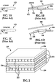
- Figure 6 is an illustration showing a simple adhesive joint configuration of a CFRP panel 610, an SMA actuator 620, a series of strip heaters 630 and thermocouple wires 640.
- the epoxy adhesive layer 650 is shown in the enlarged view of Figure 6A taken from Figure 6 .
- the strip heaters 630 are taped to the surface of the SMA actuator 620 to induce a phase transformation in the nitinol actuation.
- Figure 6 illustrates a simple 1 inch by 1 inch joint configuration for a SMA actuator 620 adhesively bonded to a CFRP panel 610 for actuation study.
- FIG. 2 wherein a perspective view of a SMA/FRPP composite structure 200 is shown.
- the nickel-titanium foils 202 are utilized which has a nominal thickness between about 0.002 inches and about 0.25 inches.
- the nickel titanium foils (or any other suitable SMA foils) 202 are incorporated into plies of fiber reinforced plies 212 (containing reinforcing fibers 220) forming the composite laminate structure 200.
- the top surface 204 and the bottom surface 206 are formed of the metal foil 202.
- a thickness of about 0.25 inches would mean a range of thickness between 0.2375 and 0.2625 inches.
- the interface 232 between the metal foil layer 202 and the fiber 330 reinforced polymeric layer 212 is structured to provide a gradient layer that transitions from the nickel-titanium metal surface to the polymeric matrix 320. This is shown in Figure 3 in an enlarged cross-sectional view.
- a sol-gel material 222 interface which functions as an adhesion promoting layer or an adhesive bond primer layer.
- the fibers 330, of carbon or other fibers, are shown in a transverse direction, or perpendicular to the paper surface, similar to that shown in Figure 2 of layer 212 in the top and bottom layers.
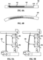
- Figures 4A and 4B illustrates cross-sectional views of a SMA/CFRP composite panel 400 in a pre-transformation and post-transformation state, respectively.
- the SMA exists in a martensite phase
- the SMA exists in an austenite phase.
- Selective placement of the plies 410 of CFRP and the SMA foil sheet 420 can produce specific morphing properties.
- the cross-sectional view of the hybrid SMA/CFRP laminate 400 shown in 4B indicates that the final shape of the structure in the SMA austenite phase can be tailored by selective placement of the SMA foil 420 within the CFRP plies 410.
- the present disclosure therefore provides the design of hybrid laminate SMA/FML (fiber metal laminate) systems to produce specific morphing properties.
- the treatment of SMA to produce a gradient layer on the surface and making it bondable to typically used epoxy prepreg system is also provided by the present disclosure.
- the present disclosure further develops and selects an adhesive that can provide a suitable transition from the nitinol foil actuator and CFRP part such that actuation can occur without degradation of the structure.
- SMA/FML structure or SMA/CFRP structure
- SMA/CFRP structure commercial aircraft adaptive trailing edge devices such as a deployable divergent trailing edge.
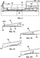
- Figures 7A-7D An illustration is shown in Figures 7A-7D . These figures illustrate an aircraft wing cross-section 700 wherein the actuators of SMA 710 are joined to a CFRP surface 715 by using an adhesive layer 720.
- Figures 7A and 7B illustrates the airfoil 700 in a stowed state prior to the phase transformation.
- Figure 7A illustrates a stowed divergent trailing edge 705 with a SMA actuator 710 adhesively bonded to a composite skin 730. Reduced weight and improved design space can be achieved by this design shown in Figure 7A.
- Figure 7B illustrates a stowed divergent trailing edge 705 with multiple 0.006-inch thick SMA foil layers 725 interlaminated in the CFRP 730.
- Figure 7C illustrates a deployed divergent trailing edge wherein the SMA actuator 710 is actuated to produce a deployed divergent trailing edge 755 wherein the SMA actuator 710 is adhesively bonded to the CFRP 730.
- Figure 7D illustrates a similar view as in Figure 7C which shows deployed divergent trailing edge 755 with laminated SMA/CFRP actuator.
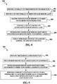
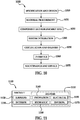
- the method 800 is started by first step 801 of providing a first plurality of carbon fiber prepreg plies, followed by step 802 of providing a second plurality of sheets of shape memory alloy; followed by step 803 of coating at least one of a top and a bottom surface of one of the second plurality of sheets of shape memory alloy with an adhesive bond primer layer; followed by step 804 of coating a layer of epoxy resin adhesive on the coated sheets of shape memory alloy; and by step 805 of interleaving coated shape memory alloy sheets with carbon fiber prepreg plies forming a laminate; and finally the step 806 of curing under heat and pressure the laminate forming the carbon fiber composite structure.
- the present disclosure further discloses a method for morphing a composite structure which is shown in Figure 9 in a flow diagram.
- the method 900 for morphing a composite structure can be started by the first step 901 of providing a first plurality of carbon fiber prepreg plies; followed by step 902 of providing a second plurality of shape memory alloy sheets each coated with an epoxy adhesive on a top and a bottom surface; followed by step 903 of interleaving the second plurality of shape memory alloy sheets with the first plurality of carbon fiber prepreg plies forming the composite structure; and finally by step 904 of morphing the composite structure by heating to a predetermined temperature at which the shape memory alloy transforms from a first crystalline state to a second crystalline state.
- embodiments of the disclosure may be used in the context of an aircraft manufacturing and service method 1000 as shown in FIG. 10 and an aircraft 1100 as shown in FIG. 11 .
- exemplary method 1000 may include specification and design 1010 of the aircraft 1100 and material procurement 1020.
- component and subassembly manufacturing 1030 and system integration 1040 of the aircraft 1100 takes place.
- the aircraft 1100 may go through certification and delivery 1050 in order to be placed in service 1060.
- routine maintenance and service 1070 which may also include modification, reconfiguration, refurbishment, and so on).
- a system integrator may include without limitation any number of aircraft manufacturers and major-system subcontractors; a third party may include without limitation any number of vendors, subcontractors, and suppliers; and an operator may be an airline, leasing company, military entity, service organization, and so on.
- the aircraft 1100 produced by exemplary method 1000 may include an airframe 1120 with a plurality of systems 1110 and an interior 1130.
- high-level systems 1110 include one or more of a propulsion system 1140, an electrical system 1150, a hydraulic system 1160, and an environmental system 1170. Any number of other systems may be included.
- an aerospace example is shown, the principles of the invention may be applied to other industries, such as the automotive industry.
- the apparatus embodied herein may be employed during any one or more of the stages of the production and service method 1000.
- components or subassemblies corresponding to production process 1030 may be fabricated or manufactured in a manner similar to components or subassemblies produced while the aircraft 1100 is in service.
- one or more apparatus embodiments may be utilized during the production stages 1030 and 1040, for example, by substantially expediting assembly of or reducing the cost of an aircraft 1100.
- one or more apparatus embodiments may be utilized while the aircraft 1100 is in service, for example and without limitation, to maintenance and service 1070.
- a method for morphing a composite structure comprising the steps of: providing a first plurality of fiber reinforced polymeric prepreg plies 212; providing a second plurality of shape memory alloy layers each coated with an adhesive on at least one of a top and bottom surfaces; and morphing said composite structure by heating to a predetermined temperature at which said shape memory alloy transforms from a first crystalline state to a second crystalline state.
- the method for morphing a composite structure includes the step of providing said plurality of shape memory alloy layers in a nickel-titanium alloy.
- the method for morphing a composite structure includes the step of heating said composite structure to a temperature of at least 110°F during said morphing step.
- the method for morphing a composite structure includes the step of heating said composite structure to a temperature between about 110°F and about 320°F during said morphing step.
Description
- The disclosure generally relates to composite structures formed by a plurality of fiber reinforced polymeric plies and a plurality of sheets of shape memory alloy, and more particularly, the disclosure relates to composite structures that have a plurality of fiber reinforced polymeric plies and a plurality of sheets of shape memory alloy that are bonded together by adhesive and wherein the shape of the composite structure can be changed by heating the shape memory alloy to a transformation temperature.
- In the aircraft industry, increasing restrictions on environmental noise and emissions as well as fuel related operating costs, have put added demand on original equipment manufacturers (OEMs) to improve aircraft efficiency. The ability of morphing and adaptive the shape of aerodynamic surfaces offers many performance benefits that can help reach these new requirements. Morphing structures such as the Variable Geometry Chevron (VGC) have demonstrated the ability to selectively control surface geometry in order to modify the jet engine exhaust stream during takeoff and cruise to reduce community noise. The Boeing-designed VGC uses shape memory alloy (SMA) bend-type actuators that undergo a thermally induced shape change that reacts with the carbon fiber reinforced plastic (CFRP) chevron surface. Other potential applications for SMA-based aero-structures include morphing wing structures for lift-to-drag improvements during cruise.
- SMAs are desirable active components for morphing structures which must be incorporated into small volume design envelopes. They are ideal for applications that require large force outputs that a motorized part could not otherwise achieve with traditional forms of actuation. Current designs for SMA-based morphing structures require metal hardware such as fasteners to join the SMA to the composite or aluminum aero-surface. The use of discrete connections can limit performance by concentrating load and thermal stresses in the SMA, fastener, and supporting structure. Fastener connections also limit design freedom by adding weight to the structure and occupying additional space.
- One of such current design for SMA-based morphing structures that require metal hardware such as fasteners is shown in
Figures 1A-1D . The design shows an airfoil cross-section illustrating a deployable divergenttrailing edge 102 for theairfoil 100.Figure 1A shows theairfoil 100 in a stowed position without the deployment. An illustrative cross-sectional view of theairfoil 100 is shown inFigure 1B as a conventional method for fastening theSMA actuator 104 to theouter surface 106 of theairfoil 100 bymechanical fasteners 108. The stowed divergenttrailing edge 102 has limited design space due to the bar actuator geometry and thefasteners 108. -
Figures 1C and 1D further show the airfoil provided with SMA actuator by mechanical fastening in a deployed condition.Figure 1C shows a divergent trailing 112 after theSMA actuator 104 has been actuated. Figure ID illustrates the deployed divergenttrailing edge 102 with theSMA actuator 104 mechanically fastened to theouter surface 106 where large localized stresses occur at location forfastener 108 in thesubstrate 106 and theactuator 104. - Accordingly, it would be advantageous to develop an adhesively bonded SMA-FRPP joint to increase morphing structure design space and efficiency.
- An adhesively bonded SMA-FRPP (Fiber Reinforced Polymeric Plies) laminate actuated structure is disclosed. SMA actuators were adhesively bonded to 121°C (250°F) cure toughened epoxy. Sol-gel surface preparation techniques were used to prepare the bonding surface of the nickel-titanium (nitinol) actuators. A hot press was used to restrain the actuator/laminate assembly during adhesive cure. Finite element analysis using a thermomechanical constitutive model of the shape-memory behavior was used to analyze stress concentrations in both the adhesively bonded and mechanically fastened structures during the actuation cycle. The performance and durability of the bonded hybrid structures was tested by measuring the laminate deflection throughout prolonged thermally induced actuation cycles. These results were then compared to similar hybrid structures joined by mechanical fastening. The disclosure demonstrates the viability and efficiency of adhesive bonding for morphing aerodynamic structures.
- The disclosure is generally directed to a composite structure having at least two carbon fiber prepreg plies, and at least one sheet of shape memory alloy in between the at least two carbon fiber prepreg plies. The sheet of shape memory alloy may have a thickness between about 0.002 inches and about 0.25 inches (conversion factor inches into centimetres: 1 inch = 2.54 cm). The sheet of shape memory alloy may also have an adhesive bond primer layer and an epoxy adhesive layer on its top and bottom surfaces.
- The disclosure is also directed to a composite structure having at least two sheets of shape memory alloy, and at least one carbon fiber prepreg ply in between the at least two sheets of shape memory alloy.
- The disclosure is further generally directed to a carbon fiber composite structure having a first plurality of carbon fiber prepreg plies and a second plurality of sheets of shape memory alloy interleaved with the first plurality of carbon fiber prepreg plies. The second plurality of sheets of the shape memory alloy each having a thickness between about 0.002 inches and 0.25 inches. The second plurality of sheets of shape memory alloy may further have at least one of its top and bottom surfaces coated with an adhesive bond primer layer and an epoxy resin adhesive layer. The adhesive bond primer layer may be a sol-gel coating layer.
- The disclosure is further generally directed to a method for fabricating a carbon fiber composite structure including the steps of providing a first plurality of carbon fiber prepreg plies; providing a second plurality of sheets of shape memory alloy; coating at least one of a top and a bottom surface of one of the second plurality of sheets of shape memory alloy with an adhesive bond primer layer; coating a layer of epoxy resin adhesive on the coated sheets of shape memory alloy; interleaving the coated sheets of shape memory alloy with at least two of the first plurality of carbon fiber prepreg plies forming a laminate; and curing under heat and pressure the laminate forming the carbon fiber composite structure.
- In some embodiments, the method for fabricating a carbon fiber composite structure may further include the step of providing the second plurality of sheets of shape memory alloy with a thickness between about 0.002 and about 0.25 inches; or providing the second plurality of sheets of shape memory alloy on at least one of the its top and bottom surfaces with an adhesive bond primer layer and an epoxy resin adhesive layer; the adhesive bond primer may be a sol-gel material, or epoxy bond primer, or both. The method may further include the step of curing the laminate at a temperature between about 200°F and about 500°F (conversion factor Fahrenheit into Centigrades: t/°C = (t/°F - 32)/1.8), and at a pressure of at least 40 PSI (conversion factor 1 psi = 6,894.76 pascals (Pa)). The actuators are joined to the interior surface of wing, not the outer surface where the airstream is.
- The disclosure is further generally directed to a method for morphing a composite structure including the steps of providing a first plurality of carbon fiber prepreg plies; providing a second plurality of shape memory alloy sheets each coated with an epoxy adhesive on a top and/or bottom surfaces; interleaving the second plurality of shape memory alloy sheets with the first plurality of carbon fiber prepreg plies forming the composite structure; and morphing the composite structure by heating to a minimum temperature at which the shape memory alloy transforms from a first crystalline state to a second crystalline state.
- In some embodiments, the method for morphing a composite structure may further include the step of providing the second plurality of shape memory alloy sheets in a nickel-titanium alloy; may further include the step of transforming a nickel-titanium alloy from a martensite structure to an austenite structure; may further include the step of heating the composite structure to a temperature of at least 110°F or may further include the step of heating the composite structure to a temperature between about 110°F and about 320°F.
-
-
Figures 1A-1D are illustrations of an airfoil cross-sections having a deployable divergent trailing edge by using SMA actuators joined to the inner surface using conventional fasteners. -
Figure 2 is a perspective view of a nickel-titanium-Fiber Reinforced Polymeric Plies hybrid laminate showing metal foils interleaved with reinforced epoxy layers. -
Figure 3 is an illustration of an enlarged, cross-sectional view of the SMA/FRPP morphing structure. -
Figures 4A and 4B are illustrations of cross-sectional views of a SMA/CFRP (Carbon Fiber Reinforced Prepreg) morphing structure prior to and after transformation, respectively. -
Figures 5A and 5B illustrates the testing arrangement for the SMA/CFRP composite panels. -
Figures 6 and 6A are a perspective view and enlarged view of the test sample of SMA/CFRP composite panel complete with heaters and thermocouple wires. -
Figure 7A-7D are illustrations of an adhesive bonded SMA/CFRP composite structure of an airfoil morphing to a divergent trailing edge. -
Figure 8 is an illustration of a flow diagram for a method of fabricating a carbon fiber composite structure. -
Figure 9 is an illustration of a flow diagram for a method of morphing a composite structure bonded together by adhesives. -
Figure 10 is an illustration of a flow diagram of an aircraft production and service methodology. -
Figure 11 is an illustration of a block diagram of an aircraft. - The following detailed description is merely exemplary in nature and is not intended to limit the described embodiments or the application and uses of the described embodiments. As used herein, the word "exemplary" or "illustrative" means "serving as an example, instance, or illustration." Any implementation described herein as "exemplary" or "illustrative" is not necessarily to be construed as preferred or advantageous over other implementations. All of the implementations described below are exemplary implementations provided to enable persons skilled in the art to practice the disclosure and are not intended to limit the scope of the appended claims. Furthermore, there is no intention to be bound by any expressed or implied theory presented in the preceding technical field, background, brief summary or the following detailed description.
- Morphing aerostructures with shape memory alloy (SMA) actuators is one approach being developed to reduce community noise from commercial aircraft. To achieve this end, two things are needed. First, the design of aerostructures that are integrally actuated with SMA materials requires an optimization approach to arrive at a successful design. This is a consequence of the unique behavior of SMA materials that requires an actuator to be under load when installed to activate its shape change properties. Second, an efficient means of integrating SMA actuators into an aerostructure is needed. Integrally placing thin sheets or foils of nitinol within the structure and controlling the interfaces is one means of achieving that.
- Shape memory alloys (SMA) can predictably change shape when undergoing a transition from the martensitic to the austenitic state over a specific temperature range. When joined to a composite structure, the structure itself can morph into shapes for specific purposes. SMA actuators can be formed into thick bars or rods of material that can be mechanically joined or bonded to the composite structure. Alternatively, SMA actuators can be formed as thin sheets or foils. When formed as thin sheets, the alloy can be incorporated into the composite structure by selectively placing the material within the ply layup of the composite. This enables the efficient design of the morphing capability specifically where the shape change capability is desired. Multiple plies of SMA foil can be placed in locations where greater deformation of the composite part is desired. The manufacture of these SMA fiber-metal laminates (FMLs) requires adhesion of the SMA surface to the composite laminate resin. Sol-gel surface preparation methods were shown to be effective in preparing SMA surfaces for adhesive bonding. A thin layer toughened epoxy adhesive, originally designed for TiGr FMLs can be used to provide strong interlaminar bonding. Careful design of the layup is needed to efficiently transfer the load between the layers during the deformation process such that the actuation is efficiently enabled and will not destroy the structure during the shape changing process.
- The preparation of test samples including SMA surface preparation and joint assembly is disclosed as follows: strips of 60-nitinol (60 weight percent nickel or any other suitable metal, and titanium) were water jet cut to dimensions of 10 inches (25.4 cm) by 1.0 inch (2.54 cm) and 0.11 inch (0.28 cm) thickness. Other nickel alloys such as NiTiPd, NiTiPt, NiTiCu, etc. may also be used as the SMA. The SMA specimens were clamped over a high-temperature tool with a 15-inch (38.1 cm) radius of curvature and heat treated in a high temperature furnace to create the shape memory effect and set the transformation temperatures. The arc height of the resulting actuators was measured at 0.79 inches (2.0 cm) equivalent to 15.4 inches (39.1 cm) radius of curvature.
- The surface of the SMA actuators was pretreated using the abrasive blasting sol-gel method according to Boeing Specification BSPS-07-001 Class 2. Actuators were immersed in an aqueous degreasing solution for 15 minutes and rinsed in cold water. They were then immersed in alkaline cleaning solution for 15 minutes and rinsed in cold water. The thermal oxide layer formed during the shape setting process was removed by abrasive blasting with 180 grit aluminum oxide. Boegel EPII solution was spray applied to the bonding surface and allowed to dry for one hour. BR6747-1 (from Cytec Engineered Materials, Inc.) epoxy bond primer was spray applied over the Boegel surface, dried at ambient conditions, and cured for 60 minutes at 250°F (121°C).
- After shape setting, the SMA actuators remain in their curved austenite shape, and required manual flattening before application of the adhesive. During this process the actuators were wrapped in cheesecloth to avoid damage and contamination of the primed surface. Wrapped actuators were cantilevered in a bench top vice and bent back against the curvature in 1-inch (2.54 cm) increments until straight.
- The one-way SMA actuators used were only capable of actively transforming to their higher temperature austenite set shape, and as such they required a preload to restore them to an initial martensite shape. Because of the large difference in strength moduli between the martensite (tensile: 4 Msi) and austenite (tensile: 8-10 Msi) phases of 60-nitinol, the stiffness of CFRP panels can be tailored by ply number and orientation to flex in the austenite phase and remain rigid in the martensite phase. Composite panels were made from epoxy prepreg in unidirectional tape and interwoven fabric form. Nine plies of prepreg were laid up with the stacking sequence in Table 1. The panel was autoclave cured at 350°F. Individual panels were cut by water jet to 4 inches (10.2 cm) by 12 inches (30.5 cm) with the 0° ribbon direction parallel to the 12 inch dimension. An area slightly larger than the bond area on the tool side of the panels in
Figure 6 was abrasive blasted with 180 grit aluminum oxide to prepare the surface for bonding.Table 1. Stacking sequence for CFRP panels Ply No. Material Orientation 1 Fabric 0/90 2 - 8 Tape 0 9 Fabric 0/90 Fabric: BMS8-276 Type 40, Class 2, Style 6K-70-PW, Form 1 Tape: BMS8-276 Type 35, Class 10, Grade 190, Form 3 - A toughened epoxy film adhesive (Hysol EA9696OST Grade 10 from Henkel) was used to join the SMA actuator to the CFRP panel. A 1 inch (2.54 cm) by 1 inch strip of the adhesive was placed at the center of the primed actuator and assembled as shown in
Figure 6 . Shims of 0.010 inches (0.254 mm) thickness were placed between the SMA and CFRP near the adhesive zone to control the bondline thickness during cure. The SMA/CFRP assemblies were placed in a heated press and allowed to cure for 90 minutes at 250°F (121°C) under 45 psi of pressure. The use of a heated press was necessary to confine the SMA from actuating during the elevated temperature cure and maintain a constant pressure at the bondline. The selection of an adhesive for use in these hybrid structures depends on the eventual application. In general, the use of highly toughened epoxy adhesives is preferred to achieve the high level of strength and durability required in the structure as well as provide the toughness necessary to withstand the peel forces and cyclic loading that occurs with each actuation cycle. - Long-term thermocycling tests were conducted on SMA beam actuators prepared by the sol-gel method and adhesively bonded to CFRP panels in order to determine joint durability and overall assembly shape during actuation. The tests were designed to track the amount of CFRP bending resulting from a thermally induced nitinol martensite to austenite phase transformation using a reflective laser deflection sensor incident on the CFRP panel. An illustration of the test setup is shown in
Figures 5A and 5B . Tests were conducted to observe the affect of adhesive type and joint geometry on final actuation shape.Laser sensors 502 measure the amount of deflection during a thermally induced nitinol phase transformation from martensite to austenite. An illustration of a simple adhesive joint configuration is shown inFigure 6 . -
Figure 6 is an illustration showing a simple adhesive joint configuration of aCFRP panel 610, anSMA actuator 620, a series ofstrip heaters 630 andthermocouple wires 640. The epoxyadhesive layer 650 is shown in the enlarged view ofFigure 6A taken fromFigure 6 . Thestrip heaters 630 are taped to the surface of the SMA actuator 620 to induce a phase transformation in the nitinol actuation.Figure 6 illustrates a simple 1 inch by 1 inch joint configuration for aSMA actuator 620 adhesively bonded to aCFRP panel 610 for actuation study. - Referring initially to
Figure 2 , wherein a perspective view of a SMA/FRPPcomposite structure 200 is shown. The nickel-titanium foils 202 are utilized which has a nominal thickness between about 0.002 inches and about 0.25 inches. The nickel titanium foils (or any other suitable SMA foils) 202 are incorporated into plies of fiber reinforced plies 212 (containing reinforcing fibers 220) forming thecomposite laminate structure 200. Thetop surface 204 and thebottom surface 206 are formed of themetal foil 202. - The word "about" used in this disclosure defines a numerical range of +/- 5 percent of the numerical number given. For instance, a thickness of about 0.25 inches would mean a range of thickness between 0.2375 and 0.2625 inches.
- The
interface 232 between themetal foil layer 202 and thefiber 330 reinforcedpolymeric layer 212 is structured to provide a gradient layer that transitions from the nickel-titanium metal surface to thepolymeric matrix 320. This is shown inFigure 3 in an enlarged cross-sectional view. - Also shown in
Figure 3 is a sol-gel material 222 interface which functions as an adhesion promoting layer or an adhesive bond primer layer. Thefibers 330, of carbon or other fibers, are shown in a transverse direction, or perpendicular to the paper surface, similar to that shown inFigure 2 oflayer 212 in the top and bottom layers. -
Figures 4A and 4B illustrates cross-sectional views of a SMA/CFRPcomposite panel 400 in a pre-transformation and post-transformation state, respectively. In the pre-transformation state, the SMA exists in a martensite phase, while in the post-transformation state, the SMA exists in an austenite phase. Selective placement of theplies 410 of CFRP and theSMA foil sheet 420 can produce specific morphing properties. - The cross-sectional view of the hybrid SMA/
CFRP laminate 400 shown in 4B indicates that the final shape of the structure in the SMA austenite phase can be tailored by selective placement of theSMA foil 420 within the CFRP plies 410. - The present disclosure therefore provides the design of hybrid laminate SMA/FML (fiber metal laminate) systems to produce specific morphing properties. The treatment of SMA to produce a gradient layer on the surface and making it bondable to typically used epoxy prepreg system is also provided by the present disclosure. The present disclosure further develops and selects an adhesive that can provide a suitable transition from the nitinol foil actuator and CFRP part such that actuation can occur without degradation of the structure.
- The disclosure enables the bonding of SMA to CFRP by adhesive means which enables more aerodynamic surfaces, lighter weight structures, and further produces more efficient hybrid actuators. The proposed applications of SMA/FML structure (or SMA/CFRP structure) include commercial aircraft adaptive trailing edge devices such as a deployable divergent trailing edge. An illustration is shown in
Figures 7A-7D . These figures illustrate anaircraft wing cross-section 700 wherein the actuators ofSMA 710 are joined to aCFRP surface 715 by using anadhesive layer 720. -
Figures 7A and 7B illustrates theairfoil 700 in a stowed state prior to the phase transformation. For instance,Figure 7A illustrates a stoweddivergent trailing edge 705 with aSMA actuator 710 adhesively bonded to acomposite skin 730. Reduced weight and improved design space can be achieved by this design shown inFigure 7A. Figure 7B illustrates a stoweddivergent trailing edge 705 with multiple 0.006-inch thickSMA foil layers 725 interlaminated in theCFRP 730. -
Figure 7C illustrates a deployed divergent trailing edge wherein theSMA actuator 710 is actuated to produce a deployeddivergent trailing edge 755 wherein theSMA actuator 710 is adhesively bonded to theCFRP 730.Figure 7D illustrates a similar view as inFigure 7C which shows deployeddivergent trailing edge 755 with laminated SMA/CFRP actuator. - Referring now to
Figure 8 , wherein a flow diagram of the present disclosure method for fabricating a carbon fiber composite structure is shown. Themethod 800 is started byfirst step 801 of providing a first plurality of carbon fiber prepreg plies, followed by step 802 of providing a second plurality of sheets of shape memory alloy; followed bystep 803 of coating at least one of a top and a bottom surface of one of the second plurality of sheets of shape memory alloy with an adhesive bond primer layer; followed bystep 804 of coating a layer of epoxy resin adhesive on the coated sheets of shape memory alloy; and bystep 805 of interleaving coated shape memory alloy sheets with carbon fiber prepreg plies forming a laminate; and finally thestep 806 of curing under heat and pressure the laminate forming the carbon fiber composite structure. - The present disclosure further discloses a method for morphing a composite structure which is shown in
Figure 9 in a flow diagram. Themethod 900 for morphing a composite structure can be started by thefirst step 901 of providing a first plurality of carbon fiber prepreg plies; followed by step 902 of providing a second plurality of shape memory alloy sheets each coated with an epoxy adhesive on a top and a bottom surface; followed bystep 903 of interleaving the second plurality of shape memory alloy sheets with the first plurality of carbon fiber prepreg plies forming the composite structure; and finally bystep 904 of morphing the composite structure by heating to a predetermined temperature at which the shape memory alloy transforms from a first crystalline state to a second crystalline state. - Referring next to
FIGS. 10 and 11 , embodiments of the disclosure may be used in the context of an aircraft manufacturing andservice method 1000 as shown inFIG. 10 and anaircraft 1100 as shown inFIG. 11 . During pre-production,exemplary method 1000 may include specification anddesign 1010 of theaircraft 1100 andmaterial procurement 1020. During production, component andsubassembly manufacturing 1030 andsystem integration 1040 of theaircraft 1100 takes place. Thereafter, theaircraft 1100 may go through certification anddelivery 1050 in order to be placed inservice 1060. While in service by a customer, theaircraft 1100 may be scheduled for routine maintenance and service 1070 (which may also include modification, reconfiguration, refurbishment, and so on). - Each of the processes of
method 1000 may be performed or carried out by a system integrator, a third party, and/or an operator (e.g., a customer). For the purposes of this description, a system integrator may include without limitation any number of aircraft manufacturers and major-system subcontractors; a third party may include without limitation any number of vendors, subcontractors, and suppliers; and an operator may be an airline, leasing company, military entity, service organization, and so on. - As shown in
FIG. 11 , theaircraft 1100 produced byexemplary method 1000 may include anairframe 1120 with a plurality ofsystems 1110 and an interior 1130. Examples of high-level systems 1110 include one or more of apropulsion system 1140, anelectrical system 1150, ahydraulic system 1160, and anenvironmental system 1170. Any number of other systems may be included. Although an aerospace example is shown, the principles of the invention may be applied to other industries, such as the automotive industry. - The apparatus embodied herein may be employed during any one or more of the stages of the production and
service method 1000. For example, components or subassemblies corresponding toproduction process 1030 may be fabricated or manufactured in a manner similar to components or subassemblies produced while theaircraft 1100 is in service. Also one or more apparatus embodiments may be utilized during theproduction stages aircraft 1100. Similarly, one or more apparatus embodiments may be utilized while theaircraft 1100 is in service, for example and without limitation, to maintenance andservice 1070. - In yet another aspect, a method is disclosed for morphing a composite structure comprising the steps of: providing a first plurality of fiber reinforced polymeric prepreg plies 212; providing a second plurality of shape memory alloy layers each coated with an adhesive on at least one of a top and bottom surfaces; and morphing said composite structure by heating to a predetermined temperature at which said shape memory alloy transforms from a first crystalline state to a second crystalline state. In one variant, the method for morphing a composite structure includes the step of providing said plurality of shape memory alloy layers in a nickel-titanium alloy. In yet another variant, the method for morphing a composite structure includes the step of heating said composite structure to a temperature of at least 110°F during said morphing step. In one alternative, the method for morphing a composite structure includes the step of heating said composite structure to a temperature between about 110°F and about 320°F during said morphing step.
- Although the embodiments of this disclosure have been described with respect to certain exemplary embodiments, it is to be understood that the specific embodiments are for purposes of illustration and not limitation, as other variations will occur to those of skill in the art.
Claims (12)
- A composite structure comprising:at least two layers of shape memory alloy; andat least one fiber reinforced polymeric layer (212) in between said at least two layers of shape memory alloy,wherein an interface (232) between a metal foil layer (202) and the fiber reinforced polymeric layer (212) is structured to provide a gradient layer that transitions from a nickel-titanium metal surface to a polymeric matrix (320).
- The composite structure according to claim 1, wherein said at least two layers of shape memory alloy each having a thickness between 0.051 +/- 5% mm and 6.35 +/- 5% mm (0.002 +/- 5% and 0.25 +/- 5% inches).
- The composite structure according to any of claims 1 or 2, wherein said at least two layers of shape memory alloy each having on one of its top and bottom surfaces at least one adhesion promoter layer (222) and a layer of an adhesive (650).
- The composite structure according to any of claims 1-3, wherein said at least one fiber reinforced polymeric layer (212) is reinforced by at least one fiber selected from the group consisting of carbon fiber and glass fiber.
- The composite structure according to any of claims 1-4, wherein said layer of an adhesive (650) is a layer of an epoxy adhesive.
- A method for morphing a composite structure comprising the steps of:providing a first plurality of fiber reinforced polymeric prepreg plies (212);providing a second plurality of shape memory alloy layers each coated with an adhesive on at least one of a top and bottom surfaces; andmorphing said composite structure by heating to a predetermined temperature at which said shape memory alloy transforms from a first crystalline state to a second crystalline state,wherein an interface (232) between a metal foil layer (202) and the fiber reinforced polymeric layer (212) is structured to provide a gradient layer that transitions from a nickel-titanium metal surface to a polymeric matrix (320).
- The method for morphing a composite structure according to claim 6 further comprising the step of providing said plurality of shape memory alloy layers in a nickel-titanium alloy.
- The method for morphing a composite structure according to any of claims 6-7 further comprising the step of heating said composite structure to a temperature of at least 43°C (110°F) during said morphing step.
- The method for morphing a composite structure according to any of claims 6-8 further comprising the step of heating said composite structure to a temperature between about 43°C (110°F) and about 160°C (320°F) during said morphing step.
- A composite structure comprising of any one of claims 1-5 that is formed by the method of any one of claims 7-11.
- A method of any one of claims 6-9 that forms a composite structure comprising any one of the claims 1-5.
- A hybrid laminate SMA/FML (fiber metal laminate) system to produce specific morphing properties of a composite structure comprising of any one of claims 1-5 that is formed by the method of any one of claims 6-9.
Applications Claiming Priority (3)
| Application Number | Priority Date | Filing Date | Title |
|---|---|---|---|
| US35154610P | 2010-06-04 | 2010-06-04 | |
| US12/917,740 US20110300358A1 (en) | 2010-06-04 | 2010-11-02 | Shape memory alloy/fiber reinforced polymeric composite structures and method for forming |
| PCT/US2011/035989 WO2011152963A1 (en) | 2010-06-04 | 2011-05-10 | Shape memory alloy/fiber reinforced polymeric composite structures and method for forming |
Publications (2)
| Publication Number | Publication Date |
|---|---|
| EP2576212A1 EP2576212A1 (en) | 2013-04-10 |
| EP2576212B1 true EP2576212B1 (en) | 2020-01-22 |
Family
ID=45064699
Family Applications (1)
| Application Number | Title | Priority Date | Filing Date |
|---|---|---|---|
| EP11721615.0A Active EP2576212B1 (en) | 2010-06-04 | 2011-05-10 | Shape memory alloy/fiber reinforced polymeric composite structures and method for forming |
Country Status (5)
| Country | Link |
|---|---|
| US (1) | US20110300358A1 (en) |
| EP (1) | EP2576212B1 (en) |
| JP (2) | JP5837579B2 (en) |
| CN (1) | CN102933387A (en) |
| WO (1) | WO2011152963A1 (en) |
Families Citing this family (40)
| Publication number | Priority date | Publication date | Assignee | Title |
|---|---|---|---|---|
| US9586699B1 (en) | 1999-08-16 | 2017-03-07 | Smart Drilling And Completion, Inc. | Methods and apparatus for monitoring and fixing holes in composite aircraft |
| US9625361B1 (en) | 2001-08-19 | 2017-04-18 | Smart Drilling And Completion, Inc. | Methods and apparatus to prevent failures of fiber-reinforced composite materials under compressive stresses caused by fluids and gases invading microfractures in the materials |
| GB0807593D0 (en) * | 2008-04-28 | 2008-06-04 | Rolls Royce Plc | A composite article comprising a shape memory material member |
| US9522512B2 (en) | 2010-08-17 | 2016-12-20 | The Boeing Company | Methods for making composite structures having composite-to-metal joints |
| EP2830857B1 (en) * | 2012-03-30 | 2019-02-06 | MBDA UK Limited | Composite material suitable for a morphing skin |
| GB2500699A (en) * | 2012-03-30 | 2013-10-02 | Mbda Uk Ltd | Composite morphing skin for an aircraft |
| GB201207525D0 (en) * | 2012-04-30 | 2012-06-13 | Airbus Operations Ltd | Morphing aerofoil |
| US10661885B2 (en) * | 2012-05-16 | 2020-05-26 | The Boeing Company | Shape memory alloy active spars for blade twist |
| DE102012112965A1 (en) | 2012-12-21 | 2014-06-26 | Leibniz-Institut Für Neue Materialien Gemeinnützige Gesellschaft Mit Beschränkter Haftung | Object with switchable adhesion |
| US9253823B2 (en) * | 2013-02-10 | 2016-02-02 | The Boeing Company | Metal matrix composite used as a heating element |
| US9610761B2 (en) | 2013-03-12 | 2017-04-04 | The Boeing Company | System and method for use in fabricating a structure |
| CN103192528B (en) * | 2013-04-24 | 2015-05-27 | 哈尔滨飞机工业集团有限责任公司 | Method for co-curing and co-moulding titanium alloy and composite material part |
| CN104339504B (en) * | 2013-08-05 | 2017-07-25 | 哈尔滨飞机工业集团有限责任公司 | The removing method of side end panel leading edge R corner recess |
| US9566746B2 (en) * | 2013-11-06 | 2017-02-14 | The Boeing Company | Methods and tools for forming contoured composite structures with shape memory alloy |
| JP6434275B2 (en) * | 2014-01-08 | 2018-12-05 | キヤノン電子株式会社 | Fiber reinforced laminate, shutter device and camera |
| US9216814B2 (en) * | 2014-03-02 | 2015-12-22 | Toyota Motor Engineering & Manufacturing North America, Inc. | Stackable wing for an aerocar |
| US9719536B2 (en) | 2014-07-03 | 2017-08-01 | The Boeing Company | Assemblies including shape memory alloy fittings and composite structural members |
| US10464281B2 (en) * | 2014-08-19 | 2019-11-05 | The Boeing Company | Sandwich composite with shape memory alloy core and method of making same |
| DE102014112772A1 (en) * | 2014-09-04 | 2016-03-10 | Thyssenkrupp Steel Europe Ag | Multi-layer composite material, method for producing and semifinished with shape memory material |
| DE102014119470A1 (en) | 2014-12-22 | 2016-06-23 | Leibniz-Institut Für Neue Materialien Gemeinnützige Gmbh | Structured surface with gradual switchable adhesion |
| US9599983B2 (en) * | 2015-01-21 | 2017-03-21 | The Boeing Company | Systems, methods, and apparatus for automated predictive shimming for large structures |
| FR3035938B1 (en) * | 2015-05-06 | 2017-06-02 | Peugeot Citroen Automobiles Sa | SUSPENSION DEVICE FOR A MOTOR VEHICLE, COMPRISING SPRINGS IN COMPOSITE MATERIAL AND SHAPE MEMORY ALLOY |
| BR112017025039A2 (en) * | 2015-05-22 | 2018-08-07 | 3M Innovative Properties Co | ? thermally stable microstructured semi-interpenetrating (semi-ipn) layer? |
| US11046058B2 (en) * | 2015-08-18 | 2021-06-29 | Hewlett-Packard Development Company, L.P. | Composite material |
| WO2017139706A1 (en) * | 2016-02-12 | 2017-08-17 | Massachusetts Institute Of Technology | Shape memory ceramic particles and structures formed thereof |
| US10253192B2 (en) * | 2016-08-29 | 2019-04-09 | The Boeing Company | Barrier coating system |
| CN106428512B (en) * | 2016-11-14 | 2018-11-02 | 泉州市泉港区鑫悦盟工业科技有限公司 | High-speed deformation aircraft |
| KR101903454B1 (en) * | 2017-01-17 | 2018-10-02 | 한국항공대학교산학협력단 | Shape memory morphing structure using kirigami patterns |
| US10919615B2 (en) * | 2017-03-29 | 2021-02-16 | The Boeing Company | Methods and apparatuses for joining titanium and titanium alloy structures to epoxy-containing compounds |
| GB2563869B (en) * | 2017-06-28 | 2023-05-17 | Qinetiq Ltd | Materials and methods |
| CN108648630B (en) * | 2018-05-31 | 2020-03-17 | 武汉华星光电半导体显示技术有限公司 | Curved screen laminating device and laminating method |
| DE102018129384A1 (en) | 2018-11-22 | 2020-05-28 | Fischerwerke Gmbh & Co. Kg | Fiber composite material |
| DE102019128494A1 (en) * | 2018-11-22 | 2020-05-28 | Fischerwerke Gmbh & Co. Kg | Clamping element for reinforcing a component in construction and method for introducing compressive stress into a component |
| CN109760341A (en) * | 2018-12-29 | 2019-05-17 | 南京航空航天大学 | The curved shape memory alloy of round trip, production method and driving method |
| US10933974B2 (en) | 2019-04-29 | 2021-03-02 | Toyota Motor Engineering & Manufacturing North America, Inc. | Morphable body with shape memory material members |
| CN110920864B (en) * | 2019-10-29 | 2022-06-17 | 南京航空航天大学 | Two-way variant mechanism and method driven by shape memory alloy thin plate |
| US11520355B2 (en) | 2021-02-26 | 2022-12-06 | Toyota Motor Engineering & Manufacturing North America, Inc. | Wing tip control effector |
| US11932390B2 (en) | 2022-04-15 | 2024-03-19 | Toyota Motor Engineering & Manufacturing North America, Inc. | Wing shape control |
| US11939055B2 (en) | 2022-04-15 | 2024-03-26 | Toyota Motor Engineering & Manufacturing North America, Inc. | Winglets with passive aeroelastic tailoring |
| CN114888533B (en) * | 2022-06-10 | 2023-02-28 | 清华大学 | Preparation method of shape memory alloy soft driver with temperature self-sensing function |
Family Cites Families (10)
| Publication number | Priority date | Publication date | Assignee | Title |
|---|---|---|---|---|
| US5866272A (en) * | 1996-01-11 | 1999-02-02 | The Boeing Company | Titanium-polymer hybrid laminates |
| US5869141A (en) * | 1996-11-04 | 1999-02-09 | The Boeing Company | Surface pretreatment for sol coating of metals |
| JP4338823B2 (en) * | 1999-05-28 | 2009-10-07 | 富士重工業株式会社 | Damage control method for composite materials |
| US6655218B1 (en) * | 1999-05-28 | 2003-12-02 | Fuji Jukogyo Kabushiki Kaisha | Composite material and method of controlling damage thereto and damage sensor |
| US6773535B1 (en) * | 2003-03-03 | 2004-08-10 | The United States Of America As Represented By The Secretary Of The Army | Article and method for controlled debonding of elements using shape memory alloy actuators |
| JP2004262191A (en) * | 2003-03-04 | 2004-09-24 | Fuji Heavy Ind Ltd | Composite material and its manufacturing method |
| US20050175813A1 (en) * | 2004-02-10 | 2005-08-11 | Wingert A. L. | Aluminum-fiber laminate |
| FR2886309B1 (en) * | 2005-05-31 | 2007-08-17 | Airbus France Sas | FLOOR FOR SOL-GEL COATING OF SURFACE AND SOL-GEL COATING PROCESS USING THE SAME |
| WO2008014058A2 (en) * | 2006-06-20 | 2008-01-31 | Usa As Represented By The Administrator Of The National Aeronautics & Space Administration | Jet engine exhaust nozzle flow effector |
| US7835130B2 (en) * | 2007-10-05 | 2010-11-16 | The Boeing Company | Method and apparatus for lightning protection of a composite structure |
-
2010
- 2010-11-02 US US12/917,740 patent/US20110300358A1/en not_active Abandoned
-
2011
- 2011-05-10 EP EP11721615.0A patent/EP2576212B1/en active Active
- 2011-05-10 WO PCT/US2011/035989 patent/WO2011152963A1/en active Application Filing
- 2011-05-10 CN CN2011800273658A patent/CN102933387A/en active Pending
- 2011-05-10 JP JP2013513185A patent/JP5837579B2/en active Active
-
2015
- 2015-11-05 JP JP2015217505A patent/JP6037411B2/en active Active
Non-Patent Citations (3)
| Title |
|---|
| MASATARO AMANO ET AL: "Evaluation of Crack Suppression Effect of TiNi SMA Foil Embedded in CFRP Cross-Ply Laminates with Embedded Small-Diameter FBG Sensor", JSME INTERNATIONAL JOURNAL, vol. 48, no. 4, 1 January 2005 (2005-01-01), pages 443 - 450, XP055226455, ISSN: 1344-7912, DOI: 10.1299/jsmea.48.443 * |
| P. CORTES ET AL: "The morphing properties of a smart fiber metal laminate", POLYMER COMPOSITES, vol. 29, no. 11, 1 November 2008 (2008-11-01), US, pages 1263 - 1268, XP055226064, ISSN: 0272-8397, DOI: 10.1002/pc.20454 * |
| PEDRO CORTES ET AL: "The fracture properties of a smart fiber metal laminate", POLYMER COMPOSITES, vol. 28, no. 4, 1 January 2007 (2007-01-01), US, pages 534 - 544, XP055226062, ISSN: 0272-8397, DOI: 10.1002/pc.20319 * |
Also Published As
| Publication number | Publication date |
|---|---|
| EP2576212A1 (en) | 2013-04-10 |
| CN102933387A (en) | 2013-02-13 |
| JP6037411B2 (en) | 2016-12-07 |
| JP2013533813A (en) | 2013-08-29 |
| JP5837579B2 (en) | 2015-12-24 |
| US20110300358A1 (en) | 2011-12-08 |
| WO2011152963A1 (en) | 2011-12-08 |
| JP2016106044A (en) | 2016-06-16 |
Similar Documents
| Publication | Publication Date | Title |
|---|---|---|
| EP2576212B1 (en) | Shape memory alloy/fiber reinforced polymeric composite structures and method for forming | |
| EP2709830B1 (en) | Aircraft structure for high capacity pull off | |
| Soutis | Fibre reinforced composites in aircraft construction | |
| Soutis | Carbon fiber reinforced plastics in aircraft construction | |
| EP2406071B1 (en) | Composite structures employing quasi-isotropic laminates | |
| Airoldi et al. | Chiral topologies for composite morphing structures–Part I: Development of a chiral rib for deformable airfoils | |
| JP6505997B2 (en) | Laminated composite corner filler with geometric filler elements and method of forming the same | |
| US8703268B2 (en) | Morphing panel structure | |
| US20120292446A1 (en) | Vertical Laminate Noodle for High Capacity Pull-Off for a Composite Stringer | |
| CA2783109C (en) | Vertical laminate noodle for high capacity pull-off for a composite stringer | |
| US20090041985A1 (en) | Composite fibre component with thermoplastic stiffening elements | |
| Heeb et al. | Manufacturing and characterisation of 3D printed thermoplastic morphing skins | |
| Soutis | Recent advances in building with composites | |
| Simpson et al. | Design and performance of a shape memory alloy-reinforced composite aerodynamic profile | |
| Boston et al. | Design and manufacturing of a multi-stable selectively stiff morphing section demonstrator | |
| Ogisu et al. | Development of damage suppression system using embedded SMA foil sensor and actuator | |
| CN107433742B (en) | Sandwich structures and associated pressure-based forming methods | |
| De Boer | Next generation fibre metal laminates | |
| Ogisu et al. | Damage suppression in CFRP laminates using embedded shape memory alloy foils | |
| Ogisu et al. | Damage behavior analysis of smart composites with embedded pre-strained SMA foils | |
| Sever | Mechanical properties of the repaired composite materials | |
| Onu et al. | Manufacturing advanced materials for aerospace application. An overview | |
| Uzawa et al. | Low cost fabrication of HOPE-X all-composite prototype structure | |
| da Silva | Enhancing Joint Performance with Residual Stresses: An Optimization Study on Adhesively Bonded Joints using Dissimilar Joints | |
| Baier et al. | Optimisation and experimental characterisation of functional hybrid material space structures |
Legal Events
| Date | Code | Title | Description |
|---|---|---|---|
| PUAI | Public reference made under article 153(3) epc to a published international application that has entered the european phase |
Free format text: ORIGINAL CODE: 0009012 |
|
| 17P | Request for examination filed |
Effective date: 20121221 |
|
| AK | Designated contracting states |
Kind code of ref document: A1 Designated state(s): AL AT BE BG CH CY CZ DE DK EE ES FI FR GB GR HR HU IE IS IT LI LT LU LV MC MK MT NL NO PL PT RO RS SE SI SK SM TR |
|
| DAX | Request for extension of the european patent (deleted) | ||
| 17Q | First examination report despatched |
Effective date: 20151113 |
|
| STAA | Information on the status of an ep patent application or granted ep patent |
Free format text: STATUS: EXAMINATION IS IN PROGRESS |
|
| GRAP | Despatch of communication of intention to grant a patent |
Free format text: ORIGINAL CODE: EPIDOSNIGR1 |
|
| STAA | Information on the status of an ep patent application or granted ep patent |
Free format text: STATUS: GRANT OF PATENT IS INTENDED |
|
| INTG | Intention to grant announced |
Effective date: 20190813 |
|
| GRAS | Grant fee paid |
Free format text: ORIGINAL CODE: EPIDOSNIGR3 |
|
| GRAJ | Information related to disapproval of communication of intention to grant by the applicant or resumption of examination proceedings by the epo deleted |
Free format text: ORIGINAL CODE: EPIDOSDIGR1 |
|
| GRAL | Information related to payment of fee for publishing/printing deleted |
Free format text: ORIGINAL CODE: EPIDOSDIGR3 |
|
| STAA | Information on the status of an ep patent application or granted ep patent |
Free format text: STATUS: EXAMINATION IS IN PROGRESS |
|
| GRAR | Information related to intention to grant a patent recorded |
Free format text: ORIGINAL CODE: EPIDOSNIGR71 |
|
| STAA | Information on the status of an ep patent application or granted ep patent |
Free format text: STATUS: GRANT OF PATENT IS INTENDED |
|
| GRAA | (expected) grant |
Free format text: ORIGINAL CODE: 0009210 |
|
| STAA | Information on the status of an ep patent application or granted ep patent |
Free format text: STATUS: THE PATENT HAS BEEN GRANTED |
|
| INTC | Intention to grant announced (deleted) | ||
| INTG | Intention to grant announced |
Effective date: 20191212 |
|
| AK | Designated contracting states |
Kind code of ref document: B1 Designated state(s): AL AT BE BG CH CY CZ DE DK EE ES FI FR GB GR HR HU IE IS IT LI LT LU LV MC MK MT NL NO PL PT RO RS SE SI SK SM TR |
|
| REG | Reference to a national code |
Ref country code: GB Ref legal event code: FG4D |
|
| REG | Reference to a national code |
Ref country code: CH Ref legal event code: EP |
|
| REG | Reference to a national code |
Ref country code: AT Ref legal event code: REF Ref document number: 1226660 Country of ref document: AT Kind code of ref document: T Effective date: 20200215 |
|
| REG | Reference to a national code |
Ref country code: IE Ref legal event code: FG4D |
|
| REG | Reference to a national code |
Ref country code: DE Ref legal event code: R096 Ref document number: 602011064726 Country of ref document: DE |
|
| REG | Reference to a national code |
Ref country code: NL Ref legal event code: MP Effective date: 20200122 |
|
| REG | Reference to a national code |
Ref country code: LT Ref legal event code: MG4D |
|
| PG25 | Lapsed in a contracting state [announced via postgrant information from national office to epo] |
Ref country code: NL Free format text: LAPSE BECAUSE OF FAILURE TO SUBMIT A TRANSLATION OF THE DESCRIPTION OR TO PAY THE FEE WITHIN THE PRESCRIBED TIME-LIMIT Effective date: 20200122 Ref country code: PT Free format text: LAPSE BECAUSE OF FAILURE TO SUBMIT A TRANSLATION OF THE DESCRIPTION OR TO PAY THE FEE WITHIN THE PRESCRIBED TIME-LIMIT Effective date: 20200614 Ref country code: NO Free format text: LAPSE BECAUSE OF FAILURE TO SUBMIT A TRANSLATION OF THE DESCRIPTION OR TO PAY THE FEE WITHIN THE PRESCRIBED TIME-LIMIT Effective date: 20200422 Ref country code: FI Free format text: LAPSE BECAUSE OF FAILURE TO SUBMIT A TRANSLATION OF THE DESCRIPTION OR TO PAY THE FEE WITHIN THE PRESCRIBED TIME-LIMIT Effective date: 20200122 Ref country code: RS Free format text: LAPSE BECAUSE OF FAILURE TO SUBMIT A TRANSLATION OF THE DESCRIPTION OR TO PAY THE FEE WITHIN THE PRESCRIBED TIME-LIMIT Effective date: 20200122 |
|
| PG25 | Lapsed in a contracting state [announced via postgrant information from national office to epo] |
Ref country code: SE Free format text: LAPSE BECAUSE OF FAILURE TO SUBMIT A TRANSLATION OF THE DESCRIPTION OR TO PAY THE FEE WITHIN THE PRESCRIBED TIME-LIMIT Effective date: 20200122 Ref country code: LV Free format text: LAPSE BECAUSE OF FAILURE TO SUBMIT A TRANSLATION OF THE DESCRIPTION OR TO PAY THE FEE WITHIN THE PRESCRIBED TIME-LIMIT Effective date: 20200122 Ref country code: HR Free format text: LAPSE BECAUSE OF FAILURE TO SUBMIT A TRANSLATION OF THE DESCRIPTION OR TO PAY THE FEE WITHIN THE PRESCRIBED TIME-LIMIT Effective date: 20200122 Ref country code: GR Free format text: LAPSE BECAUSE OF FAILURE TO SUBMIT A TRANSLATION OF THE DESCRIPTION OR TO PAY THE FEE WITHIN THE PRESCRIBED TIME-LIMIT Effective date: 20200423 Ref country code: IS Free format text: LAPSE BECAUSE OF FAILURE TO SUBMIT A TRANSLATION OF THE DESCRIPTION OR TO PAY THE FEE WITHIN THE PRESCRIBED TIME-LIMIT Effective date: 20200522 Ref country code: BG Free format text: LAPSE BECAUSE OF FAILURE TO SUBMIT A TRANSLATION OF THE DESCRIPTION OR TO PAY THE FEE WITHIN THE PRESCRIBED TIME-LIMIT Effective date: 20200422 |
|
| REG | Reference to a national code |
Ref country code: DE Ref legal event code: R097 Ref document number: 602011064726 Country of ref document: DE |
|
| PG25 | Lapsed in a contracting state [announced via postgrant information from national office to epo] |
Ref country code: SK Free format text: LAPSE BECAUSE OF FAILURE TO SUBMIT A TRANSLATION OF THE DESCRIPTION OR TO PAY THE FEE WITHIN THE PRESCRIBED TIME-LIMIT Effective date: 20200122 Ref country code: SM Free format text: LAPSE BECAUSE OF FAILURE TO SUBMIT A TRANSLATION OF THE DESCRIPTION OR TO PAY THE FEE WITHIN THE PRESCRIBED TIME-LIMIT Effective date: 20200122 Ref country code: EE Free format text: LAPSE BECAUSE OF FAILURE TO SUBMIT A TRANSLATION OF THE DESCRIPTION OR TO PAY THE FEE WITHIN THE PRESCRIBED TIME-LIMIT Effective date: 20200122 Ref country code: LT Free format text: LAPSE BECAUSE OF FAILURE TO SUBMIT A TRANSLATION OF THE DESCRIPTION OR TO PAY THE FEE WITHIN THE PRESCRIBED TIME-LIMIT Effective date: 20200122 Ref country code: CZ Free format text: LAPSE BECAUSE OF FAILURE TO SUBMIT A TRANSLATION OF THE DESCRIPTION OR TO PAY THE FEE WITHIN THE PRESCRIBED TIME-LIMIT Effective date: 20200122 Ref country code: RO Free format text: LAPSE BECAUSE OF FAILURE TO SUBMIT A TRANSLATION OF THE DESCRIPTION OR TO PAY THE FEE WITHIN THE PRESCRIBED TIME-LIMIT Effective date: 20200122 Ref country code: ES Free format text: LAPSE BECAUSE OF FAILURE TO SUBMIT A TRANSLATION OF THE DESCRIPTION OR TO PAY THE FEE WITHIN THE PRESCRIBED TIME-LIMIT Effective date: 20200122 Ref country code: DK Free format text: LAPSE BECAUSE OF FAILURE TO SUBMIT A TRANSLATION OF THE DESCRIPTION OR TO PAY THE FEE WITHIN THE PRESCRIBED TIME-LIMIT Effective date: 20200122 |
|
| REG | Reference to a national code |
Ref country code: AT Ref legal event code: MK05 Ref document number: 1226660 Country of ref document: AT Kind code of ref document: T Effective date: 20200122 |
|
| PLBE | No opposition filed within time limit |
Free format text: ORIGINAL CODE: 0009261 |
|
| STAA | Information on the status of an ep patent application or granted ep patent |
Free format text: STATUS: NO OPPOSITION FILED WITHIN TIME LIMIT |
|
| 26N | No opposition filed |
Effective date: 20201023 |
|
| PG25 | Lapsed in a contracting state [announced via postgrant information from national office to epo] |
Ref country code: MC Free format text: LAPSE BECAUSE OF FAILURE TO SUBMIT A TRANSLATION OF THE DESCRIPTION OR TO PAY THE FEE WITHIN THE PRESCRIBED TIME-LIMIT Effective date: 20200122 Ref country code: AT Free format text: LAPSE BECAUSE OF FAILURE TO SUBMIT A TRANSLATION OF THE DESCRIPTION OR TO PAY THE FEE WITHIN THE PRESCRIBED TIME-LIMIT Effective date: 20200122 Ref country code: LI Free format text: LAPSE BECAUSE OF NON-PAYMENT OF DUE FEES Effective date: 20200531 Ref country code: CH Free format text: LAPSE BECAUSE OF NON-PAYMENT OF DUE FEES Effective date: 20200531 Ref country code: IT Free format text: LAPSE BECAUSE OF FAILURE TO SUBMIT A TRANSLATION OF THE DESCRIPTION OR TO PAY THE FEE WITHIN THE PRESCRIBED TIME-LIMIT Effective date: 20200122 |
|
| PG25 | Lapsed in a contracting state [announced via postgrant information from national office to epo] |
Ref country code: SI Free format text: LAPSE BECAUSE OF FAILURE TO SUBMIT A TRANSLATION OF THE DESCRIPTION OR TO PAY THE FEE WITHIN THE PRESCRIBED TIME-LIMIT Effective date: 20200122 Ref country code: PL Free format text: LAPSE BECAUSE OF FAILURE TO SUBMIT A TRANSLATION OF THE DESCRIPTION OR TO PAY THE FEE WITHIN THE PRESCRIBED TIME-LIMIT Effective date: 20200122 |
|
| REG | Reference to a national code |
Ref country code: BE Ref legal event code: MM Effective date: 20200531 |
|
| PG25 | Lapsed in a contracting state [announced via postgrant information from national office to epo] |
Ref country code: LU Free format text: LAPSE BECAUSE OF NON-PAYMENT OF DUE FEES Effective date: 20200510 |
|
| PG25 | Lapsed in a contracting state [announced via postgrant information from national office to epo] |
Ref country code: IE Free format text: LAPSE BECAUSE OF NON-PAYMENT OF DUE FEES Effective date: 20200510 |
|
| PG25 | Lapsed in a contracting state [announced via postgrant information from national office to epo] |
Ref country code: BE Free format text: LAPSE BECAUSE OF NON-PAYMENT OF DUE FEES Effective date: 20200531 |
|
| PG25 | Lapsed in a contracting state [announced via postgrant information from national office to epo] |
Ref country code: TR Free format text: LAPSE BECAUSE OF FAILURE TO SUBMIT A TRANSLATION OF THE DESCRIPTION OR TO PAY THE FEE WITHIN THE PRESCRIBED TIME-LIMIT Effective date: 20200122 Ref country code: MT Free format text: LAPSE BECAUSE OF FAILURE TO SUBMIT A TRANSLATION OF THE DESCRIPTION OR TO PAY THE FEE WITHIN THE PRESCRIBED TIME-LIMIT Effective date: 20200122 Ref country code: CY Free format text: LAPSE BECAUSE OF FAILURE TO SUBMIT A TRANSLATION OF THE DESCRIPTION OR TO PAY THE FEE WITHIN THE PRESCRIBED TIME-LIMIT Effective date: 20200122 |
|
| PG25 | Lapsed in a contracting state [announced via postgrant information from national office to epo] |
Ref country code: MK Free format text: LAPSE BECAUSE OF FAILURE TO SUBMIT A TRANSLATION OF THE DESCRIPTION OR TO PAY THE FEE WITHIN THE PRESCRIBED TIME-LIMIT Effective date: 20200122 Ref country code: AL Free format text: LAPSE BECAUSE OF FAILURE TO SUBMIT A TRANSLATION OF THE DESCRIPTION OR TO PAY THE FEE WITHIN THE PRESCRIBED TIME-LIMIT Effective date: 20200122 |
|
| P01 | Opt-out of the competence of the unified patent court (upc) registered |
Effective date: 20230516 |
|
| PGFP | Annual fee paid to national office [announced via postgrant information from national office to epo] |
Ref country code: FR Payment date: 20230525 Year of fee payment: 13 Ref country code: DE Payment date: 20230530 Year of fee payment: 13 |
|
| PGFP | Annual fee paid to national office [announced via postgrant information from national office to epo] |
Ref country code: GB Payment date: 20230529 Year of fee payment: 13 |