EP4414135A1 - Work machine - Google Patents
Work machine Download PDFInfo
- Publication number
- EP4414135A1 EP4414135A1 EP22878383.3A EP22878383A EP4414135A1 EP 4414135 A1 EP4414135 A1 EP 4414135A1 EP 22878383 A EP22878383 A EP 22878383A EP 4414135 A1 EP4414135 A1 EP 4414135A1
- Authority
- EP
- European Patent Office
- Prior art keywords
- weight
- vibration reduction
- weight member
- power transmission
- disposed
- Prior art date
- Legal status (The legal status is an assumption and is not a legal conclusion. Google has not performed a legal analysis and makes no representation as to the accuracy of the status listed.)
- Pending
Links
Images





Classifications
-
- B—PERFORMING OPERATIONS; TRANSPORTING
- B25—HAND TOOLS; PORTABLE POWER-DRIVEN TOOLS; MANIPULATORS
- B25D—PERCUSSIVE TOOLS
- B25D17/00—Details of, or accessories for, portable power-driven percussive tools
- B25D17/24—Damping the reaction force
-
- B—PERFORMING OPERATIONS; TRANSPORTING
- B25—HAND TOOLS; PORTABLE POWER-DRIVEN TOOLS; MANIPULATORS
- B25D—PERCUSSIVE TOOLS
- B25D11/00—Portable percussive tools with electromotor or other motor drive
- B25D11/06—Means for driving the impulse member
- B25D11/12—Means for driving the impulse member comprising a crank mechanism
- B25D11/125—Means for driving the impulse member comprising a crank mechanism with a fluid cushion between the crank drive and the striking body
-
- B—PERFORMING OPERATIONS; TRANSPORTING
- B25—HAND TOOLS; PORTABLE POWER-DRIVEN TOOLS; MANIPULATORS
- B25D—PERCUSSIVE TOOLS
- B25D16/00—Portable percussive machines with superimposed rotation, the rotational movement of the output shaft of a motor being modified to generate axial impacts on the tool bit
-
- B—PERFORMING OPERATIONS; TRANSPORTING
- B25—HAND TOOLS; PORTABLE POWER-DRIVEN TOOLS; MANIPULATORS
- B25D—PERCUSSIVE TOOLS
- B25D2211/00—Details of portable percussive tools with electromotor or other motor drive
- B25D2211/003—Crossed drill and motor spindles
-
- B—PERFORMING OPERATIONS; TRANSPORTING
- B25—HAND TOOLS; PORTABLE POWER-DRIVEN TOOLS; MANIPULATORS
- B25D—PERCUSSIVE TOOLS
- B25D2217/00—Details of, or accessories for, portable power-driven percussive tools
- B25D2217/0073—Arrangements for damping of the reaction force
- B25D2217/0076—Arrangements for damping of the reaction force by use of counterweights
- B25D2217/0092—Arrangements for damping of the reaction force by use of counterweights being spring-mounted
-
- B—PERFORMING OPERATIONS; TRANSPORTING
- B25—HAND TOOLS; PORTABLE POWER-DRIVEN TOOLS; MANIPULATORS
- B25D—PERCUSSIVE TOOLS
- B25D2250/00—General details of portable percussive tools; Components used in portable percussive tools
- B25D2250/245—Spatial arrangement of components of the tool relative to each other
Definitions
- the present invention relates to a working machine.
- a gear housing is provided in an outer housing constituting an outer shell of the working machine.
- a power transmission mechanism is provided in the gear housing, and striking power in the front-rear direction is applied to a tip tool by the power transmission mechanism.
- the working machine includes a vibration reduction mechanism, and the vibration reduction mechanism reduces vibration generated by the power transmission mechanism. As a result, for example, workability for the worker can be improved.
- Patent Literature 1 WO 2015/166995
- the vibration reduction mechanism is disposed between the gear housing and the outer housing. Specifically, the vibration reduction mechanism is respectively disposed outside the gear housing in the right-left direction. Therefore, the size of the working machine tends to increase.
- an object of the present invention is to provide a working machine capable of improving workability while achieving downsizing.
- a working machine include: a driving source; a tip tool; a power transmission unit connected to the driving source and the tip tool, the power transmission unit including a tubular member having a cylindrical shape with a first direction as an axial direction, the power transmission unit being operated by the driving source to apply striking force in the first direction to the tip tool; a case that accommodates at least the tubular member; and a vibration reduction unit that is accommodated in the case and reduces vibration in the first direction generated in the case.
- the vibration reduction unit includes a guide member extending in the first direction, a weight member supported by the guide member to be relatively movable in the first direction, and a biasing member that biases the weight member in the first direction.
- the weight member is disposed to overlap with the tubular member in a second direction orthogonal to the first direction and a third direction orthogonal to the first direction and the second direction as viewed in a first direction, and the biasing member is disposed to be shifted in the second direction with respect to a center of gravity of the weight member as viewed in a first direction.
- the power transmission unit may include a power transmission member, and as viewed in a first direction, the power transmission member may extend in the third direction on one side in the second direction with respect to the tubular member, and at least a part of the weight member may be sandwiched in the second direction by the tubular member and the power transmission member.
- the power transmission member may be a gear that has the second direction as an axial direction and transmits rotational force to the tubular member.
- the weight member may have a curved surface extending along a circumferential direction of the tubular member.
- the weight member may be supported by a pair of the guide members disposed apart from each other in the second direction.
- the biasing member may be a coil spring attached to the guide member.
- a pair of the vibration reduction units may be provided inside the case, and the vibration reduction units may be respectively disposed on one side and the other side in the third direction with respect to the tubular member.
- the weight member in the pair of vibration reduction units may be connected by a weight coupling part.
- the vibration reduction unit may include a holder that supports both end portions of the guide member in the longitudinal direction, and the holder may be brought into pressure contact with a wall surface of the case by a biasing force of the biasing member.
- workability can be improved while achieving downsizing.
- a hammer drill 10 as a working machine according to the present embodiment will be described with reference to Figs. 1 to 7 .
- the hammer drill 10 is configured as a tool for performing drilling or the like on a workpiece.
- arrows UP, FR, and RH appropriately illustrated in the drawings indicate the upper side, the front side, and the right side of the hammer drill 10.
- the up-down, front-rear, and right-left directions of the hammer drill 10 are indicated, unless otherwise specified.
- the front-back direction corresponds to the first direction of the present invention
- the up-down direction corresponds to the second direction of the present invention
- the right-left direction corresponds to the third direction of the present invention.
- the lower side corresponds to one side in the second direction of the present invention.
- hatching is appropriately omitted in the drawings for convenience.
- the hammer drill 10 includes a housing 12, a motor 34 as a driving source accommodated in the housing 12, and a power transmission mechanism 40 as a power transmission unit that transmits the driving force of the motor 34 to a tip tool T.
- the hammer drill 10 includes a mode switching mechanism unit 66, and is configured such that a transmission path to the tip tool T in the power transmission mechanism 40 is switched by operating a switching lever 67 of the mode switching mechanism unit 66, and the hammer drill 10 is switched to a hammer mode for applying a striking force to the tip tool T or a hammer drill mode for applying a rotational force and a striking force to the tip tool T.
- the hammer drill 10 includes a pair of right and left vibration reduction mechanisms 80 (see Figs. 2 and 3 ) as a vibration reduction unit, and the vibration reduction mechanisms 80 absorb vibration in the front-rear direction generated when the hammer drill 10 is operated.
- a pair of right and left vibration reduction mechanisms 80 see Figs. 2 and 3
- the vibration reduction mechanisms 80 absorb vibration in the front-rear direction generated when the hammer drill 10 is operated.
- the housing 12 is formed in a hollow shape and constitutes an outer shell of the hammer drill 10.
- the housing 12 includes a main body housing 14 and a handle 16 disposed on the rear side (one side in the front-rear direction) of the main body housing 14.
- the main body housing 14 extends in the front-rear direction, and a rear end portion of the main body housing 14 protrudes downward.
- the main body housing 14 includes a plurality of housing members.
- the handle 16 extends in the up-down direction, and an upper end portion and a lower end portion of the handle 16 are connected to the main body housing 14 by a vibration damping mechanism 20, so that the handle 16 is configured to be relatively movable in the front-rear direction with respect to the main body housing 14.
- the vibration damping mechanism 20 includes a hinge connection part 21 that connects the lower end portion of the handle 16 to the main body housing 14, and the hinge connection part 21 is rotatably connected to the rear lower end portion of the main body housing 14 with the right-left direction as the axial direction.
- the vibration damping mechanism 20 includes an elastic connection part 22 that connects the upper end portion of the handle 16 to the main body housing 14.
- the elastic connection part 22 is made of an elastic material such as an elastomer, and is formed in a tubular and bellows shape whose axial direction is the front-rear direction, and both end portions of the elastic connection part 22 in the front-rear direction are integrally formed with the handle 16 and the main body housing 14.
- the vibration damping mechanism 20 includes a vibration damping spring 23 configured as a compression coil spring, and the vibration damping spring 23 is disposed in the elastic connection part 22 and biases the handle 16 and the main body housing 14 outward in the front-rear direction. Furthermore, the vibration damping mechanism 20 includes a stopper mechanism (not illustrated), and the handle 16 is held in a non-press position illustrated in Fig. 1 . In addition, the handle 16 is configured to be displaced from the non-press position to the front side by pushing the handle 16 to the front side at the time of machining the workpiece.
- An intermediate portion of the handle 16 in the up-down direction is configured as a grip part 16A gripped by an operator.
- a trigger 26 is provided at the upper portion of the grip part 16A.
- the trigger 26 is formed in a substantially long block shape extending in the up-down direction and is exposed to the front side from the grip part 16A in an operable manner.
- a lower end portion of the trigger 26 is rotatably connected to the handle 16 with the right-left direction as an axial direction, and the trigger 26 is configured to be pulled rearward.
- a switch 28 is provided on the rear side of the trigger 26. When the operator pulls the trigger 26, the switch 28 is turned on.
- the switch 28 is electrically connected to a controller 30 provided at the lower end portion of the main body housing 14, and outputs an output signal corresponding to the operation state of the trigger 26 to the controller 30.
- a power cord 32 is provided at a lower end portion of the handle 16, and the power cord 32 extends downward from the handle 16 to be connectable to a commercial power source.
- the power cord 32 is electrically connected to the controller 30, and power is supplied from a commercial power source to the controller 30 via the power cord 32.
- the motor 34 is configured as a three-phase brushless motor, accommodated in the lower portion of the main body housing 14, and disposed on the front side of the controller 30.
- the motor 34 includes a drive shaft 34A whose axial direction is the up-down direction, a substantially cylindrical rotor 34B fixed to the drive shaft 34A, and a substantially cylindrical stator 34C disposed radially outside the rotor 34B.
- a lower end portion of the drive shaft 34A is rotatably supported by a bearing 35, and an upper end side portion of the drive shaft 34Ais rotatably supported by a bearing 36.
- a pinion gear 34A1 is formed at an upper end portion of the drive shaft 34A.
- the motor 34 is electrically connected to the controller 30 and is driven under the control of the controller 30.
- the power transmission mechanism 40 includes a crank mechanism unit 42, a rotation mechanism unit 47, and a power applying mechanism unit 53.
- the power transmission mechanism 40 is accommodated in an inner case 72 as a case, and the inner case 72 is accommodated in an upper portion of the main body housing 14.
- the crank mechanism unit 42 and the rotation mechanism unit 47 constitute a lower portion of the power transmission mechanism 40
- the power applying mechanism unit 53 constitutes an upper portion of the power transmission mechanism 40
- the crank mechanism unit 42 and the rotation mechanism unit 47 are arranged side by side in the front-rear direction.
- the configuration of the inner case 72 will be described first, and then each configuration of the power transmission mechanism 40 will be described.
- the inner case 72 includes a case body 73 and a case cover 74, and the case cover 74 is assembled to the case body 73 to form the inner case 72.
- a rear portion of the case body 73 is configured as a gear case part 73A, and the gear case part 73A is formed in a substantially recessed shape that is opened upward.
- the front portion of the case body 73 is configured as a tubular case part 73B, and the tubular case part 73B is formed in a substantially cylindrical shape with the front-rear direction as the axial direction and extends forward from the upper portion of the gear case part 73A.
- the case cover 74 is formed in a substantially plate shape with the up-down direction as a plate thickness direction and is assembled to an upper opening of the gear case part 73A to close the opening.
- the bearing 36 supporting the drive shaft 34A of the motor 34 described above is fixed to a bottom wall of the gear case part 73A, and the pinion gear 34A1 of the drive shaft 34A is disposed in the lower end portion of the gear case part 73A.
- crank mechanism unit 42 As shown in Fig. 1 , the crank mechanism unit 42 is accommodated in the rear portion of the gear case part 73A.
- the crank mechanism unit 42 includes a crankshaft 43 and a crank gear 44.
- the crankshaft 43 is formed in a substantially bottomed cylindrical shape that is opened downward, is disposed on the rear side of the pinion gear 34A1 of the motor 34, and a lower end portion of the crankshaft 43 is fixed to the bottom wall of the gear case part 73A.
- the crank gear 44 is formed in a substantially cylindrical shape whose axial direction is the up-down direction and is rotatably supported by the crankshaft 43 via a bearing 45.
- a gear portion is formed on an outer periphery of a lower end portion of the crank gear 44, and the gear portion is meshed with the pinion gear 34A1 of the motor 34.
- a connection shaft 44A protruding upward is provided at an upper end portion of the crank gear 44, and the connection shaft 44A is disposed at a position eccentric to the center of the crankshaft 43.
- the rotation mechanism unit 47 is accommodated in the front portion of the gear case part 73A.
- the rotation mechanism unit 47 includes a rotating shaft 48 and a transmission gear 50 as a power transmission member.
- the rotating shaft 48 is formed in a substantially columnar shape with the up-down direction as the axial direction, is disposed on the front side of the pinion gear 34A1 of the motor 34, and a lower portion of the rotating shaft 48 is rotatably supported by the bottom wall of the gear case part 73A via a bearing 49.
- a ring gear 48A is formed at the upper end portion of the rotating shaft 48.
- the transmission gear 50 is formed in a substantially disk shape with the up-down direction as the plate thickness direction and is integrally and rotatably connected to an upper end side portion of the rotating shaft 48.
- the transmission gear 50 includes a slip clutch 51, and the transmission gear 50 and the rotating shaft 48 are connected by the slip clutch 51.
- a recessed portion opened downward is formed on a lower surface of the transmission gear 50, and the slip clutch 51 is disposed in the recessed portion to connect the transmission gear 50 and the rotating shaft 48.
- a gear portion is formed on an outer periphery of the transmission gear 50, and the gear portion is meshed with the pinion gear 34A1 of the motor 34.
- the slip clutch 51 is configured as a so-called torque limiter mechanism and is configured to prevent the motor 34 from being overload by the slip clutch 51.
- the transmission gear 50 constitutes the outermost shape portion of the power transmission mechanism 40 in the right-left direction. That is, in the power transmission mechanism 40, the transmission gear 50 is configured as the largest member in the right-left direction. As a result, the maximum dimension of the inner case 72 (gear case part 73A) in the right-left direction is set by the diameter of the transmission gear 50.
- the power applying mechanism unit 53 includes a cylinder 54, a retainer sleeve 55, a ring gear 56 as a tubular member, a clutch 58, a piston 60, a strike element 63, and an intermediate element 64.
- the cylinder 54 and the retainer sleeve 55 are formed in a substantially cylindrical shape whose axial direction is the front-rear direction and are coaxially disposed.
- the front end portion of the cylinder 54 is fitted into the rear end portion of the retainer sleeve 55, and the cylinder 54 and the retainer sleeve 55 are connected to rotate integrally.
- the cylinder 54 and the retainer sleeve 55 are accommodated in the upper portion of the gear case part 73A of the inner case 72 and the tubular case part 73B. More specifically, the rear end portion of the cylinder 54 is disposed on the upper side of the rotation mechanism unit 47 and on the front side of the connection shaft 44A in the crank mechanism unit 42.
- the front end portion of the retainer sleeve 55 protrudes further forward than the inner case 72.
- the cylinder 54 and the retainer sleeve 55 are rotatably supported by the inner case 72 and the main body housing 14 via bearings. Further, the tip tool T is attached to the front end portion of the retainer sleeve 55 and protrudes forward from the front end portion of the main body housing 14.
- the ring gear 56 is formed in a substantially cylindrical shape whose axial direction is the front-rear direction, is externally inserted into a rear end side portion of the cylinder 54, and is rotatably supported by the cylinder 54. Specifically, the ring gear 56 is disposed on the upper side of the transmission gear 50 and is accommodated in the gear case part 73A. A ring gear 56A is formed at a rear end portion of the ring gear 56, and the ring gear 56A is meshed with the ring gear 48A of the rotating shaft 48 in the rotation mechanism unit 47.
- the rear end portion of the ring gear 56 is bent in a substantially crank shape radially outward and protrudes radially outward as compared with the other portion of the ring gear 56 in a longitudinal cross-sectional view.
- the axis AL1 of the transmission gear 50 described above passes through the axis AL2 of the ring gear 56 (cylinder 54).
- the outermost diameter dimension of the ring gear 56 is set to be smaller than the diameter of the transmission gear 50 (see Fig. 4 ), and the ring gear 56 constitutes the outermost shape portion in the right-left direction in the upper portion (power applying mechanism unit 53) of the power transmission mechanism 40.
- the clutch 58 is formed in a substantially cylindrical shape whose axial direction is the front-rear direction, and is externally inserted into the cylinder 54 on the rear side of the ring gear 56.
- the clutch 58 is spline-fitted to the cylinder 54. That is, the clutch 58 is connected to the cylinder 54 to rotate integrally and relatively movable in the front-rear direction.
- the front end portion of the clutch 58 is disposed radially inside the rear end portion of the ring gear 56 and is engaged with the ring gear 56 in the circumferential direction.
- the driving force of the motor 34 is transmitted to the cylinder 54 by the rotation mechanism unit 47, the ring gear 56, and the clutch 58, and the cylinder 54 and the retainer sleeve 55 rotate to apply the rotational force to the tip tool T.
- the clutch 58 is moved rearward by the mode switching mechanism unit 66 to be described later, the engagement state between the clutch 58 and the ring gear 56 is released, and the transmission of the driving force from the rotation mechanism unit 47 to the cylinder 54 is cut off.
- the piston 60 is formed in a substantially bottomed cylindrical shape that is opened rearward and is inserted into the rear portion of the cylinder 54 to be relatively movable in the front-rear direction. Further, the piston 60 is provided with a piston connection shaft 61 whose axial direction is the up-down direction. A front end portion of a piston rod 62 extending in the front-rear direction is rotatably connected to the piston connection shaft 61, and a rear end portion of the piston rod 62 is rotatably connected to the connection shaft 44A of the crank mechanism unit 42.
- the driving force of the motor 34 is transmitted to the piston 60 by the crank mechanism unit 42 and the piston rod 62, and the piston 60 reciprocates in the front-rear direction.
- the strike element 63 is formed in a substantially columnar shape whose axial direction is the front-rear direction and is inserted into the cylinder 54 to be relatively movable in the front-rear direction.
- the strike element 63 is disposed apart from the front side of the piston 60, and a space between the piston 60 and the strike element 63 in the cylinder 54 is configured as an air chamber 54A.
- the intermediate element 64 is formed in a substantially cylindrical shape whose axial direction is the front-rear direction and is inserted into the retainer sleeve 55 to be relatively movable in the front-rear direction.
- the intermediate element 64 is disposed adjacent to the front side of the strike element 63.
- the mode switching mechanism unit 66 includes the switching lever 67 and a switching arm 69.
- the switching lever 67 is formed in a substantially bottomed cylindrical shape that is opened downward, is disposed at the rear end portion of the main body housing 14, and is exposed to be operable upward from the main body housing 14.
- a lever shaft 68 is fixed to a central portion of the switching lever 67, and the lever shaft 68 is formed in a substantially cylindrical shape whose axial direction is the up-down direction and protrudes downward from the switching lever 67.
- the lever shaft 68 is rotatably supported by the case cover 74 of the inner case 72.
- the switching arm 69 is formed in a substantially elongated shape extending in the front-rear direction.
- a front end portion of the switching arm 69 is connected to the clutch 58 of the power applying mechanism unit 53, and a rear end portion of the switching arm 69 is connected to the lever shaft 68 via an arm connection shaft 70.
- the arm connection shaft 70 is disposed at a position eccentric to the central axis of the lever shaft 68. Accordingly, when the switching lever 67 rotates, the switching arm 69 is displaced in the front-rear direction.
- the switching arm 69 is disposed at the position illustrated in Fig. 1 , and the ring gear 56 and the clutch 58 are engaged with each other.
- the switching arm 69 is displaced rearward, and the engagement state between the ring gear 56 and the clutch 58 is released.
- the pair of right and left vibration reduction mechanisms 80 is respectively accommodated in both end portions of the gear case part 73A of the inner case 72 in the right-left direction.
- the pair of right and left vibration reduction mechanisms 80 is accommodated in the space S on the upper side of the transmission gear 50 in the gear case part 73A and on both sides of the ring gear 56 in the right-left direction.
- the pair of right and left vibration reduction mechanisms 80 is configured to be bilaterally symmetrical with respect to the center portion of the inner case 72 in the right-left direction. Therefore, in the following description, the vibration reduction mechanism 80 on the right side will be described, and the description of the vibration reduction mechanism 80 on the left side will be appropriately omitted.
- the vibration reduction mechanism 80 includes a pair of front and rear holders 82, an upper guide shaft 84 and a lower guide shaft 86 as guide members, a weight member 90, and a pair of front and rear weight springs 96 as biasing members.
- the pair of holders 82 is formed in a substantially rectangular plate shape with the front-rear direction as the plate thickness direction and the up-down direction as the longitudinal direction, and constitutes both end portions of the vibration reduction mechanism 80 in the front-rear direction.
- the lower end portion of the holder 82 is engaged with the inner case 72 in the front-rear direction and the right-left direction, and the upper end portion of the holder 82 is engaged with the case cover 74 in the front-rear direction and the right-left direction to be fixed to the inner case 72.
- the front holder 82 is biased forward by the front weight spring 96 to be described later, and the rear holder 82 is biased rearward side by the rear weight spring 96, so that the pair of holders 82 is brought into pressure contact with the wall surface of the case body 73.
- the fixed state of the holders 82 (vibration reduction mechanism 80) is maintained.
- a pair of right and left upper bearing parts 82A is formed at upper portions of the pair of front and rear holders 82.
- the upper bearing part 82A is formed in a substantially cylindrical shape with the front-rear direction as the axial direction and protrudes inward in the front-rear direction from the holder 82.
- Lower bearing parts 82B are formed at lower portions of the pair of holders 82.
- the lower bearing part 82B is formed in a substantially cylindrical shape with the front-rear direction as the axial direction and protrudes inward in the front-rear direction from the holder 82.
- the upper guide shaft 84 and the lower guide shaft 86 are formed in a substantially cylindrical shape with the front-rear direction as the axial direction. Further, both end portions in the longitudinal direction of the upper guide shaft 84 are fitted into the upper bearing parts 82A on the outer side (that is, the right side) in the right-left direction of the holder 82, and the upper guide shaft 84 is held by the pair of front and rear holders 82. Further, both end portions in the longitudinal direction of the lower guide shaft 86 are fitted into the lower bearing part 82B of the holder 82, and the lower guide shaft 86 is held by the pair of front and rear holders 82.
- the lower guide shaft 86 is disposed closer to the inner side (the ring gear 56 side) in the right-left direction than the upper guide shaft 84.
- the upper guide shaft 84 is disposed slightly lower than the axis AL2 of the ring gear 56 as viewed in the front-rear direction.
- Ring-shaped dampers 88 are externally fitted on both end portions of the upper guide shaft 84 in the front-rear direction.
- the ring-shaped damper 88 is made of an elastic material such as rubber and is configured as a member that alleviates a collision between the weight member 90 to be described later and the upper bearing parts 82A of the holder 82.
- the weight member 90 includes a weight part 92 constituting an upper portion of the weight member 90 and a spring mounting part 94 constituting a lower portion of the weight member 90.
- the weight part 92 is formed in a substantially inverted T-shaped block shape when the right-left direction is defined as a thickness direction and when viewed from the right-left direction.
- An upper guide hole 92A is formed to penetrate the lower end portion of the weight part 92 in the front-rear direction. Then, the upper guide shaft 84 is inserted into the upper guide hole 92A, and the weight part 92 is supported by the upper guide shaft 84 to be relatively movable in the front-rear direction.
- the center of gravity G (see Fig. 4 ) of the weight member 90 is disposed at a position overlapping the weight part 92 when viewed from the front-rear direction. Specifically, the center of gravity G of the weight member 90 is located in the vicinity of the upper guide hole 92A when viewed from the front-rear direction.
- the spring mounting part 94 is formed in a plate shape with the front-rear direction as a plate thickness direction and extends downward from a center portion of the weight part 92 in the front-rear direction.
- the spring mounting part 94 is formed with a pair of front and rear mounting tubular parts 94A for mounting the weight spring 96 to be described later.
- the mounting tubular part 94A is formed in a cylindrical shape with the front-rear direction as the axial direction and protrudes outward in the front-rear direction from the spring mounting part 94.
- the inside of the mounting tubular part 94A is configured as a lower guide hole 94B, and the lower guide hole 94B penetrates in the front-rear direction so that the inside of the pair of front and rear mounting tubular parts 94A communicates with each other. Then, the lower guide shaft 86 is inserted into the lower guide hole 94B, and the spring mounting part 94 is supported by the lower guide shaft 86 to be relatively movable in the front-rear direction. As a result, in the weight member 90, the spring mounting part 94 for mounting the weight spring 96 and the weight part 92 functioning as a weight part are disposed to be shifted in the up-down direction.
- the weight member 90 is disposed close to the right side of the ring gear 56, and substantially the entire weight member 90 and the ring gear 56 overlap in the right-left direction (see Fig. 4 ). Specifically, the upper end of the weight member 90 is disposed lower than the uppermost end of the ring gear 56, and the lower end of the weight member 90 is disposed slightly lower than the lowermost end of the ring gear 56. In addition, the position of the weight member 90 in the front-rear direction is set such that the entire weight member 90 overlaps the transmission gear 50 when viewed from above.
- the outer shape of the spring mounting part 94 is formed in a substantially circular shape centered on the lower guide hole 94B when viewed from the front-rear direction, and the outer peripheral surface of the weight part 92 and the outer peripheral surface of the spring mounting part 94 are smoothly connected.
- a curved surface 90A is formed on an inner surface (that is, the left side surface facing the ring gear 56 in the radial direction) in the right-left direction of the weight member 90.
- the curved surface 90A is curved in an arc shape centered on the axis AL2 of the ring gear 56 when viewed from the front-rear direction, is formed at the lower portion of the weight part 92 and the upper portion of the spring mounting part 94, and is smoothly connected to the lower surface of the spring mounting part 94.
- a part of the spring mounting part 94 is disposed to be extended to the left side of the weight part 92 and bite into the space S between the ring gear 56 and the transmission gear 50.
- the weight member 90 extends in the up-down direction along the circumferential direction of the ring gear 56 on the right side of the ring gear 56.
- the outermost shape part (the part where the ring gear 56A is formed) of the ring gear 56 and a part of the weight member 90 overlap each other in the up-down direction.
- a side surface 90B on the outer side in the right-left direction of the weight member 90 is formed in a planar shape along a surface orthogonal to the right-left direction and is smoothly connected to the lower surface of the spring mounting part 94.
- the side surfaces 90B of the weight member 90 are disposed close to the right and left side surfaces of the gear case part 73 A.
- the pair of front and rear weight springs 96 is configured as a compression coil spring.
- the weight spring 96 is disposed on the outer side in the front-rear direction of the spring mounting part 94 in the weight member 90 and is attached to the lower guide shaft 86 on the lower side. Specifically, the rear end portion of the front weight spring 96 is extrapolated to the front mounting tubular part 94A, and the front end portion of the front weight spring 96 is extrapolated to the lower bearing part 82B of the front holder 82.
- the front end portion of the rear weight spring 96 is extrapolated to the mounting tubular part 94A on the rear side, and the rear end portion of the rear weight spring 96 is extrapolated to the lower bearing part 82B of the rear holder 82.
- the weight spring 96 is disposed at a position shifted downward with respect to the weight part 92 (the center of gravity G of the weight member 90).
- the center AL3 of the weight spring 96 is disposed at a position different from the center of gravity G of the weight member 90 as viewed in the front-rear direction.
- the center of gravity G of the weight member 90 is disposed outside the disposition range of the weight spring 96 as viewed in the front-rear direction.
- the front weight spring 96 biases the spring mounting part 94 rearward, and the rear weight spring 96 biases the spring mounting part 94 to the front side, so that the weight member 90 is held in a state of being located at the center in the front-rear direction of the upper guide shaft 84 and the lower guide shaft 86.
- the radius of the weight spring 96 is set slightly smaller than the radius of the spring mounting part 94 of the weight member 90 and is set so that the weight spring 96 does not protrude from the spring mounting part 94 as viewed from the front-rear direction.
- the ring gear 56 and the clutch 58 are engaged by the switching arm 69 of the mode switching mechanism unit 66.
- the crank mechanism unit 42 and the rotation mechanism unit 47 are operated, and the striking force and the rotational force are applied from the power applying mechanism unit 53 to the tip tool T.
- the clutch 58 is displaced rearward by the switching arm 69 of the mode switching mechanism unit 66, and the engagement state between the ring gear 56 and the clutch 58 is released.
- the crank mechanism unit 42 is operated, and only the striking force is applied from the power applying mechanism unit 53 to the tip tool T.
- the striking force in the front-rear direction due to the operation of the power transmission mechanism 40 is applied to the tip tool T.
- the vibration that is generated during operation of the power transmission mechanism 40 is transmitted to the inner case 72.
- the vibration reduction mechanism 80 is provided inside the inner case 72.
- the vibration reduction mechanism 80 includes the weight member 90, and the weight member 90 is supported by the pair of upper and lower guide shafts 84 and 86 to be relatively movable in the front-rear direction. Further, the weight member 90 is biased in the front-rear direction by the pair of front and rear weight springs 96. As a result, the weight member 90 vibrates in the front-rear direction during operation of the power transmission mechanism 40, so that vibration energy transmitted to the inner case 72 can be absorbed by the vibration reduction mechanism 80. Therefore, since the vibration transmitted to the operator is reduced, the workability of the hammer drill 10 can be improved.
- the weight member 90 is disposed at a position overlapping the ring gear 56 in the right-left direction and the up-down direction when viewed from the front-rear direction, and the weight spring 96 is disposed to be shifted downward with respect to the center of gravity G of the weight member 90 when viewed from the front-rear direction.
- the spring mounting part 94 to which the weight spring 96 is mounted and the weight part 92 functioning as a weight part where the center of gravity G is located are disposed to be shifted in the up-down direction, and the weight part 92 extends upward from the spring mounting part 94.
- the weight of the comparative example is formed in a cylindrical shape with the front-rear direction as the axial direction. That is, the weight of the comparative example has a structure in which a weight part functioning as a weight part and a spring mounting part for mounting the weight spring 96 are not shifted in the up-down direction.
- a weight member of the comparative example is movably connected to the upper guide shaft 84 or the lower guide shaft 86 and the weight member of the comparative example is biased so as to be sandwiched from the outside in the front-rear direction by the pair of front and rear weight springs 96, it is necessary to increase the size of the weight member in order to secure the weight of the weight member.
- the weight member of the comparative example when the size of the weight member is increased in the radial direction, it is necessary to increase the size of the inner case 72 in the right-left direction and the up-down direction. Further, for example, in the weight member of the comparative example, when the size of the weight member is increased in the front-rear direction, it is necessary to increase the size of the inner case 72 in the front-rear direction. This may increase the size of the hammer drill 10.
- the weight member 90 is disposed in the inner case 72 at a position overlapping the ring gear 56 in the right-left direction and the up-down direction as viewed from the front-rear direction.
- the spring mounting part 94 to which the weight spring 96 is mounted and the weight part 92 functioning as a weight part are disposed to be shifted in the right-left direction. That is, the weight member 90 can be extended in the up-down direction along the circumferential direction of the ring gear 56 on the outside in the right-left direction of the ring gear 56. Therefore, as compared with the weight member of the above-described comparative example, the size of the weight member 90 can be reduced, and the size of the hammer drill 10 can be reduced. As described above, workability can be improved while downsizing the hammer drill 10.
- the vibration reduction mechanism 80 is provided outside the inner case 72 .
- the wall surface of the inner case 72 is interposed between the space in the inner case 72 in which the power transmission mechanism 40 is accommodated and the space in which the vibration reduction mechanism 80 is accommodated, it is difficult to dispose the weight member 90 so as to overlap the ring gear 56 in the up-down direction and the right-left direction.
- the size of the hammer drill 10 may be increased.
- the weight member 90 can be disposed so as to overlap the ring gear 56 in the up-down direction and the right-left direction, and it is not necessary to provide an outer wall other than the inner case 72, and thus the hammer drill 10 can be downsized.
- the weight part 92 is disposed outside the ring gear 56 (cylinder 54) in the right-left direction, and the spring mounting part 94 is disposed at the lower side of the weight part 92.
- the weight part 92 where the center of gravity G of the weight member 90 is located is disposed slightly lower than the axis AL2 of the ring gear 56 (cylinder 54), and the spring mounting part 94 is disposed at the lower side of the weight part 92.
- the center of gravity G of the weight member 90 can be disposed near the axis AL2 in the up-down direction. That is, as compared with a configuration in which the weight part 92 is movably connected to the lower guide shaft 86 and the spring mounting part 94 is movably connected to the upper guide shaft 84, the amount of offset in the up-down direction of the center of gravity G of the weight member 90 from the axis AL2 can be reduced.
- the center of gravity G of the weight member 90 can be disposed on the outer side in the right-left direction of the cylinder 54 accommodating the piston 60 and the strike element 63 that apply the striking force in the front-rear direction to the tip tool T. Therefore, the vibration reduction effect of the vibration reduction mechanism 80 can be enhanced.
- the power transmission mechanism 40 includes the transmission gear 50.
- the transmission gear 50 When viewed from the front-rear direction, the transmission gear 50 extends in the right-left direction below the ring gear 56, and at least a part of the weight member 90 is sandwiched by the ring gear 56 and the transmission gear 50 in the right-left direction.
- the spring mounting part 94 of the weight member 90 is extended toward the ring gear 56 from the weight part 92, and the extended part is sandwiched by the ring gear 56 and the transmission gear 50 in the up-down direction.
- a portion between the ring gear 56 and the transmission gear 50 in the space S of the gear case part 73A can be utilized to dispose a part of the spring mounting part 94 and the weight spring 96. Therefore, it is possible to prevent the weight spring 96 from protruding outward in the right-left direction from the weight member 90 while securing the diameter (spring diameter) of the weight spring 96.
- the curved surface 90A is formed on the inner surface in the right-left direction of the weight member 90, and the curved surface 90A is formed in an arc shape extending along the circumferential direction of the ring gear 56. This makes it possible to secure the weight of the weight member 90 while disposing the weight member 90 close to the ring gear 56. As a result, it is possible to effectively contribute to downsizing of the size of the weight member 90 in the right-left direction.
- the weight member 90 is supported by the pair of upper and lower guide shafts 84 and 86 so as to be relatively movable in the front-rear direction. As a result, the weight member 90 can be disposed along the circumferential direction of the ring gear 56 while stabilizing the posture of the weight member 90.
- the weight spring 96 is a compression coil spring mounted on the lower guide shaft 86. As a result, the weight member 90 can be biased in the front-rear direction by the weight spring 96 while stabilizing the posture of the weight spring 96 by the lower guide shaft 86.
- a pair of right and left vibration reduction mechanisms 80 is provided in the inner case 72, and the vibration reduction mechanisms 80 are disposed on both sides in the right-left direction with respect to the ring gear 56.
- the vibration transmitted to the inner case 72 during the operation of the power transmission mechanism 40 can be absorbed in a balanced manner by the pair of vibration reduction mechanisms 80.
- the vibration reduction mechanism 80 includes a pair of front and rear holders 82 that support both end portions in the longitudinal direction of the upper guide shaft 84 and the lower guide shaft 86, and the holder 82 is brought into pressure contact with the gear case part 73A in the inner case 72 by the biasing force of the weight spring 96.
- the fixed state of the holder 82 to the inner case 72 can be favorably maintained by utilizing the biasing force of the weight spring 96 that biases the weight member 90 in the front-rear direction.
- the vibration reduction mechanism 80 is also disposed in the inner case 72 in which the power transmission mechanism 40 is accommodated, the power transmission mechanism 40 can also be maintained when the inner case 72 is opened for maintenance of the power transmission mechanism 40, and the maintainability of the hammer drill 10 is improved. Furthermore, since a lubricant such as grease applied to the power transmission mechanism 40 to lubricate the power transmission mechanism 40 can be scattered to the vibration reduction mechanism 80 during driving, the power transmission mechanism 40 is also lubricated and is less likely to be worn, and reliability is improved.
- the first modification of the vibration reduction mechanism 80 is configured similarly to the vibration reduction mechanism 80 of the present embodiment except for the following points. Note that, in Fig. 8 , the vibration reduction mechanism 80 disposed on the right side is illustrated, and in Fig. 8 , the same reference numerals are given to parts configured similarly to the vibration reduction mechanism 80 of the present embodiment.
- the upper guide shaft 84 is omitted in the vibration reduction mechanism 80, and the weight member 90 is supported only by the lower guide shaft 86.
- the lower guide shaft 86 is formed in a non-circular shape when viewed from the longitudinal direction thereof. In the present modification, the lower guide shaft 86 is formed in a substantially track shape in cross section.
- the weight member 90 In the weight member 90, the upper guide hole 92A is omitted, and the lower guide hole 94B is formed in a long hole shape corresponding to the outer shape of the lower guide shaft 86. As a result, the weight member 90 is connected to the lower guide shaft 86 so as to be relatively movable in the front-rear direction and relatively non-rotatable.
- the weight member 90 can be disposed on the radially outer side of the ring gear 56 along the circumferential direction of the ring gear 56, the spring mounting part 94 to which the weight spring 96 is mounted is extended toward the ring gear 56, so that the weight spring 96 can be disposed below the center of gravity G of the weight member 90 and toward the ring gear 56. Therefore, also in the first modification of the vibration reduction mechanism 80, workability can be improved while downsizing the hammer drill 10.
- the upper guide shaft 84 is omitted in the vibration reduction mechanism 80. Therefore, it is possible to reduce the number of components and the number of assembling steps and contribute to cost reduction of the vibration reduction mechanism 80.
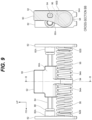
- the second modification of the vibration reduction mechanism 80 is configured similarly to the vibration reduction mechanism 80 of the present embodiment except for the following points. Note that, in Fig. 9 , the vibration reduction mechanism 80 disposed on the right side is illustrated, and in Fig. 9 , the same reference numerals are given to parts configured similarly to the vibration reduction mechanism 80 of the present embodiment.
- the lower guide shaft 86 is omitted in the vibration reduction mechanism 80, and the weight member 90 is supported only by the upper guide shaft 84.
- the upper guide shaft 84 is formed in a non-circular shape when viewed from the longitudinal direction thereof.
- the weight member 90 In the weight member 90, the lower guide hole 94B is omitted, and the upper guide hole 92A is formed in a long hole shape corresponding to the outer shape of the upper guide shaft 84. As a result, the weight member 90 is coupled to the upper guide shaft 84 so as to be relatively movable in the front-rear direction and relatively non-rotatable.
- the weight member 90 can be disposed on the radially outer side of the ring gear 56 along the circumferential direction of the ring gear 56, the spring mounting part 94 to which the weight spring 96 is mounted is extended toward the ring gear 56, so that the weight spring 96 can be disposed below the center of gravity G of the weight member 90 and toward the ring gear 56. Therefore, also in the second modification of the vibration reduction mechanism 80, workability can be improved while downsizing the hammer drill 10.
- the upper guide shaft 84 is omitted in the vibration reduction mechanism 80. Therefore, it is possible to reduce the number of components and the number of assembling steps and contribute to cost reduction of the vibration reduction mechanism 80.
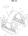
- the third modification of the vibration reduction mechanism 80 is configured similarly to the vibration reduction mechanism 80 of the present embodiment except for the following points. Note that, in Figs. 10 and 11 , the same reference numerals are given to parts configured similarly to the vibration reduction mechanism 80 of the present embodiment.
- a coupling arm 98 as a weight coupling part for connecting the weight members 90 in the pair of right and left vibration reduction mechanisms 80 is provided.
- the coupling arm 98 is disposed on the upper side of the ring gear 56 and is formed in a substantially semicircular plate shape that is opened downward along the circumferential direction of the ring gear 56. Both end portions in the longitudinal direction of the coupling arm 98 are connected to the upper end of the weight member 90.
- the pair of right and left vibration reduction mechanisms 80 operates integrally.
- the weight member 90 can be disposed on the radially outer side of the ring gear 56 along the circumferential direction of the ring gear 56, the spring mounting part 94 to which the weight spring 96 is mounted is extended toward the ring gear 56, so that the weight spring 96 can be disposed below the center of gravity G of the weight member 90 and toward the ring gear 56. Therefore, also in the third modification of the vibration reduction mechanism 80, workability can be improved while downsizing the hammer drill 10.
- the pair of right and left vibration reduction mechanisms 80 can be integrally operated by the coupling arm 98.
- the total weight of the right and left weight members 90 can be made heavier than that in the present embodiment. Therefore, for example, the overall weight of the weight member 90 can be adjusted in accordance with the resonance frequency during operation in various hammer drills. Therefore, it is possible to absorb vibration generated during operation corresponding to various hammer drills.
Landscapes
- Engineering & Computer Science (AREA)
- Mechanical Engineering (AREA)
- Percussive Tools And Related Accessories (AREA)
Abstract
Description
- The present invention relates to a working machine.
- In the working machine described in Patent Literature 1 below, a gear housing is provided in an outer housing constituting an outer shell of the working machine. In addition, a power transmission mechanism is provided in the gear housing, and striking power in the front-rear direction is applied to a tip tool by the power transmission mechanism. The working machine includes a vibration reduction mechanism, and the vibration reduction mechanism reduces vibration generated by the power transmission mechanism. As a result, for example, workability for the worker can be improved.
- Patent Literature 1:
WO 2015/166995 - However, in the above-described working machine, the vibration reduction mechanism is disposed between the gear housing and the outer housing. Specifically, the vibration reduction mechanism is respectively disposed outside the gear housing in the right-left direction. Therefore, the size of the working machine tends to increase.
- The present invention has been made in consideration of the above-described facts, an object of the present invention is to provide a working machine capable of improving workability while achieving downsizing.
- According to one or more embodiments of the present invention, a working machine include: a driving source; a tip tool; a power transmission unit connected to the driving source and the tip tool, the power transmission unit including a tubular member having a cylindrical shape with a first direction as an axial direction, the power transmission unit being operated by the driving source to apply striking force in the first direction to the tip tool; a case that accommodates at least the tubular member; and a vibration reduction unit that is accommodated in the case and reduces vibration in the first direction generated in the case. The vibration reduction unit includes a guide member extending in the first direction, a weight member supported by the guide member to be relatively movable in the first direction, and a biasing member that biases the weight member in the first direction. The weight member is disposed to overlap with the tubular member in a second direction orthogonal to the first direction and a third direction orthogonal to the first direction and the second direction as viewed in a first direction, and the biasing member is disposed to be shifted in the second direction with respect to a center of gravity of the weight member as viewed in a first direction.
- In the working machine according to one or more embodiments of the present invention, the power transmission unit may include a power transmission member, and as viewed in a first direction, the power transmission member may extend in the third direction on one side in the second direction with respect to the tubular member, and at least a part of the weight member may be sandwiched in the second direction by the tubular member and the power transmission member.
- In the working machine according to one or more embodiments of the present invention, the power transmission member may be a gear that has the second direction as an axial direction and transmits rotational force to the tubular member.
- In the working machine according to one or more embodiments of the present invention, the weight member may have a curved surface extending along a circumferential direction of the tubular member.
- In the working machine according to one or more embodiments of the present invention, the weight member may be supported by a pair of the guide members disposed apart from each other in the second direction.
- In the working machine according to one or more embodiments of the present invention, the biasing member may be a coil spring attached to the guide member.
- In the working machine according to one or more embodiments of the present invention, a pair of the vibration reduction units may be provided inside the case, and the vibration reduction units may be respectively disposed on one side and the other side in the third direction with respect to the tubular member.
- In the working machine according to one or more embodiments of the present invention, the weight member in the pair of vibration reduction units may be connected by a weight coupling part.
- In the working machine according to one or more embodiments of the present invention, the vibration reduction unit may include a holder that supports both end portions of the guide member in the longitudinal direction, and the holder may be brought into pressure contact with a wall surface of the case by a biasing force of the biasing member.
- According to one or more embodiments of the present invention, workability can be improved while achieving downsizing.
-
-
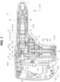
Fig. 1 is a longitudinal cross-sectional view of a hammer drill according to the present embodiment as viewed from the right side. -
Fig. 2 is a perspective view illustrating a state in which a power transmission mechanism and a vibration reduction mechanism are accommodated in an inner case illustrated inFig. 1 as viewed from diagonally rear left. -
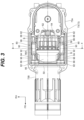
Fig. 3 is a plan view illustrating a state in which the power transmission mechanism and the vibration reduction mechanism illustrated inFig. 2 are accommodated in the inner case as viewed from above. -
Fig. 4 is a cross-sectional view (a cross-sectional view taken along line 4-4 inFig. 3 ) illustrating a state in which the power transmission mechanism and the vibration reduction mechanism illustrated inFig. 3 are accommodated in the inner case as viewed from the rear side. -
Fig. 5 is an enlarged perspective view illustrating a state in which the vibration reduction mechanism illustrated inFig. 2 is accommodated in the inner case as viewed from diagonally rear left. -
Fig. 6(A) is an enlarged perspective view illustrating the vibration reduction mechanism on the right side illustrated inFig. 5 , andFig. 6(B) is a side view of the vibration reduction mechanism illustrated inFig. 6(A) as viewed from the left side. -
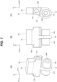
Fig. 7(A) is a perspective view illustrating a weight member of the vibration reduction mechanism illustrated inFig. 6(A) ,Fig. 7(B) is a side view of the weight member illustrated inFig. 6(A) as viewed from the left side, andFig. 7(C) is a rear view of the weight member illustrated inFig. 6(A) as viewed from the rear side. -
Fig. 8 is a left side view illustrating a first modification of the vibration reduction mechanism used in the hammer drill according to the present embodiment. -
Fig. 9 is a left side view illustrating a second modification of the vibration reduction mechanism used in the hammer drill according to the present embodiment. -
Fig. 10 is a perspective view illustrating a third modification of the vibration reduction mechanism used in the hammer drill according to the present embodiment as viewed from diagonally rear left. -
Fig. 11 is a cross-sectional view corresponding toFig. 4 illustrating a state in which the vibration reduction mechanism illustrated inFig. 10 is accommodated in the inner case. - A
hammer drill 10 as a working machine according to the present embodiment will be described with reference toFigs. 1 to 7 . Thehammer drill 10 is configured as a tool for performing drilling or the like on a workpiece. Note that arrows UP, FR, and RH appropriately illustrated in the drawings indicate the upper side, the front side, and the right side of thehammer drill 10. In the following description, when explaining by using up-down, front-rear, and right-left directions, the up-down, front-rear, and right-left directions of thehammer drill 10 are indicated, unless otherwise specified. The front-back direction corresponds to the first direction of the present invention, the up-down direction corresponds to the second direction of the present invention, and the right-left direction corresponds to the third direction of the present invention. Further, the lower side corresponds to one side in the second direction of the present invention. Furthermore, hatching is appropriately omitted in the drawings for convenience. - As illustrated in
Fig. 1 , thehammer drill 10 includes ahousing 12, amotor 34 as a driving source accommodated in thehousing 12, and apower transmission mechanism 40 as a power transmission unit that transmits the driving force of themotor 34 to a tip tool T. In addition, thehammer drill 10 includes a modeswitching mechanism unit 66, and is configured such that a transmission path to the tip tool T in thepower transmission mechanism 40 is switched by operating aswitching lever 67 of the modeswitching mechanism unit 66, and thehammer drill 10 is switched to a hammer mode for applying a striking force to the tip tool T or a hammer drill mode for applying a rotational force and a striking force to the tip tool T. In addition, thehammer drill 10 includes a pair of right and left vibration reduction mechanisms 80 (seeFigs. 2 and3 ) as a vibration reduction unit, and thevibration reduction mechanisms 80 absorb vibration in the front-rear direction generated when thehammer drill 10 is operated. Hereinafter, each configuration of thehammer drill 10 will be described. - (Regarding Housing 12) The
housing 12 is formed in a hollow shape and constitutes an outer shell of thehammer drill 10. Thehousing 12 includes amain body housing 14 and ahandle 16 disposed on the rear side (one side in the front-rear direction) of themain body housing 14. Themain body housing 14 extends in the front-rear direction, and a rear end portion of themain body housing 14 protrudes downward. Themain body housing 14 includes a plurality of housing members. - The
handle 16 extends in the up-down direction, and an upper end portion and a lower end portion of thehandle 16 are connected to themain body housing 14 by avibration damping mechanism 20, so that thehandle 16 is configured to be relatively movable in the front-rear direction with respect to themain body housing 14. Thevibration damping mechanism 20 includes ahinge connection part 21 that connects the lower end portion of thehandle 16 to themain body housing 14, and thehinge connection part 21 is rotatably connected to the rear lower end portion of themain body housing 14 with the right-left direction as the axial direction. Thevibration damping mechanism 20 includes anelastic connection part 22 that connects the upper end portion of thehandle 16 to themain body housing 14. Theelastic connection part 22 is made of an elastic material such as an elastomer, and is formed in a tubular and bellows shape whose axial direction is the front-rear direction, and both end portions of theelastic connection part 22 in the front-rear direction are integrally formed with thehandle 16 and themain body housing 14. - In addition, the
vibration damping mechanism 20 includes avibration damping spring 23 configured as a compression coil spring, and thevibration damping spring 23 is disposed in theelastic connection part 22 and biases thehandle 16 and the main body housing 14 outward in the front-rear direction. Furthermore, thevibration damping mechanism 20 includes a stopper mechanism (not illustrated), and thehandle 16 is held in a non-press position illustrated inFig. 1 . In addition, thehandle 16 is configured to be displaced from the non-press position to the front side by pushing thehandle 16 to the front side at the time of machining the workpiece. - An intermediate portion of the
handle 16 in the up-down direction is configured as agrip part 16A gripped by an operator. Atrigger 26 is provided at the upper portion of thegrip part 16A. Thetrigger 26 is formed in a substantially long block shape extending in the up-down direction and is exposed to the front side from thegrip part 16A in an operable manner. A lower end portion of thetrigger 26 is rotatably connected to thehandle 16 with the right-left direction as an axial direction, and thetrigger 26 is configured to be pulled rearward. In thehandle 16, aswitch 28 is provided on the rear side of thetrigger 26. When the operator pulls thetrigger 26, theswitch 28 is turned on. Theswitch 28 is electrically connected to acontroller 30 provided at the lower end portion of themain body housing 14, and outputs an output signal corresponding to the operation state of thetrigger 26 to thecontroller 30. - A
power cord 32 is provided at a lower end portion of thehandle 16, and thepower cord 32 extends downward from thehandle 16 to be connectable to a commercial power source. Thepower cord 32 is electrically connected to thecontroller 30, and power is supplied from a commercial power source to thecontroller 30 via thepower cord 32. - (Regarding Motor 34) The
motor 34 is configured as a three-phase brushless motor, accommodated in the lower portion of themain body housing 14, and disposed on the front side of thecontroller 30. Themotor 34 includes adrive shaft 34A whose axial direction is the up-down direction, a substantiallycylindrical rotor 34B fixed to thedrive shaft 34A, and a substantiallycylindrical stator 34C disposed radially outside therotor 34B. A lower end portion of thedrive shaft 34A is rotatably supported by abearing 35, and an upper end side portion of the drive shaft 34Ais rotatably supported by abearing 36. A pinion gear 34A1 is formed at an upper end portion of thedrive shaft 34A. Themotor 34 is electrically connected to thecontroller 30 and is driven under the control of thecontroller 30. - (Regarding Power Transmission Mechanism 40) The
power transmission mechanism 40 includes acrank mechanism unit 42, arotation mechanism unit 47, and a power applyingmechanism unit 53. Thepower transmission mechanism 40 is accommodated in aninner case 72 as a case, and theinner case 72 is accommodated in an upper portion of themain body housing 14. In thepower transmission mechanism 40, thecrank mechanism unit 42 and therotation mechanism unit 47 constitute a lower portion of thepower transmission mechanism 40, the power applyingmechanism unit 53 constitutes an upper portion of thepower transmission mechanism 40, and thecrank mechanism unit 42 and therotation mechanism unit 47 are arranged side by side in the front-rear direction. Hereinafter, the configuration of theinner case 72 will be described first, and then each configuration of thepower transmission mechanism 40 will be described. - (Regarding Inner Case 72) As shown in
Figs. 1 to 5 , theinner case 72 includes acase body 73 and acase cover 74, and the case cover 74 is assembled to thecase body 73 to form theinner case 72. A rear portion of thecase body 73 is configured as agear case part 73A, and thegear case part 73A is formed in a substantially recessed shape that is opened upward. The front portion of thecase body 73 is configured as atubular case part 73B, and thetubular case part 73B is formed in a substantially cylindrical shape with the front-rear direction as the axial direction and extends forward from the upper portion of thegear case part 73A. The case cover 74 is formed in a substantially plate shape with the up-down direction as a plate thickness direction and is assembled to an upper opening of thegear case part 73A to close the opening. The bearing 36 supporting thedrive shaft 34A of themotor 34 described above is fixed to a bottom wall of thegear case part 73A, and the pinion gear 34A1 of thedrive shaft 34A is disposed in the lower end portion of thegear case part 73A. - (Regarding Crank Mechanism Unit 42) As shown in
Fig. 1 , thecrank mechanism unit 42 is accommodated in the rear portion of thegear case part 73A. Thecrank mechanism unit 42 includes acrankshaft 43 and acrank gear 44. Thecrankshaft 43 is formed in a substantially bottomed cylindrical shape that is opened downward, is disposed on the rear side of the pinion gear 34A1 of themotor 34, and a lower end portion of thecrankshaft 43 is fixed to the bottom wall of thegear case part 73A. Thecrank gear 44 is formed in a substantially cylindrical shape whose axial direction is the up-down direction and is rotatably supported by thecrankshaft 43 via abearing 45. A gear portion is formed on an outer periphery of a lower end portion of thecrank gear 44, and the gear portion is meshed with the pinion gear 34A1 of themotor 34. Aconnection shaft 44A protruding upward is provided at an upper end portion of thecrank gear 44, and theconnection shaft 44A is disposed at a position eccentric to the center of thecrankshaft 43. - (Regarding Rotation Mechanism 47) As illustrated in
Figs. 1 and4 , therotation mechanism unit 47 is accommodated in the front portion of thegear case part 73A. Therotation mechanism unit 47 includes arotating shaft 48 and atransmission gear 50 as a power transmission member. The rotatingshaft 48 is formed in a substantially columnar shape with the up-down direction as the axial direction, is disposed on the front side of the pinion gear 34A1 of themotor 34, and a lower portion of therotating shaft 48 is rotatably supported by the bottom wall of thegear case part 73A via abearing 49. Aring gear 48A is formed at the upper end portion of therotating shaft 48. - The
transmission gear 50 is formed in a substantially disk shape with the up-down direction as the plate thickness direction and is integrally and rotatably connected to an upper end side portion of therotating shaft 48. Thetransmission gear 50 includes aslip clutch 51, and thetransmission gear 50 and therotating shaft 48 are connected by theslip clutch 51. Specifically, a recessed portion opened downward is formed on a lower surface of thetransmission gear 50, and theslip clutch 51 is disposed in the recessed portion to connect thetransmission gear 50 and therotating shaft 48. A gear portion is formed on an outer periphery of thetransmission gear 50, and the gear portion is meshed with the pinion gear 34A1 of themotor 34. In addition, when a rotational torque of a predetermined value or more acts on theslip clutch 51, the connection state between therotating shaft 48 and thetransmission gear 50 by theslip clutch 51 is released. That is, theslip clutch 51 is configured as a so-called torque limiter mechanism and is configured to prevent themotor 34 from being overload by theslip clutch 51. In addition, thetransmission gear 50 constitutes the outermost shape portion of thepower transmission mechanism 40 in the right-left direction. That is, in thepower transmission mechanism 40, thetransmission gear 50 is configured as the largest member in the right-left direction. As a result, the maximum dimension of the inner case 72 (gear case part 73A) in the right-left direction is set by the diameter of thetransmission gear 50. - (Regarding Power Applying Mechanism Unit 53) As illustrated in
Figs. 1 to 4 , the power applyingmechanism unit 53 includes acylinder 54, aretainer sleeve 55, aring gear 56 as a tubular member, a clutch 58, apiston 60, astrike element 63, and anintermediate element 64. - The
cylinder 54 and theretainer sleeve 55 are formed in a substantially cylindrical shape whose axial direction is the front-rear direction and are coaxially disposed. In addition, the front end portion of thecylinder 54 is fitted into the rear end portion of theretainer sleeve 55, and thecylinder 54 and theretainer sleeve 55 are connected to rotate integrally. Thecylinder 54 and theretainer sleeve 55 are accommodated in the upper portion of thegear case part 73A of theinner case 72 and thetubular case part 73B. More specifically, the rear end portion of thecylinder 54 is disposed on the upper side of therotation mechanism unit 47 and on the front side of theconnection shaft 44A in thecrank mechanism unit 42. On the other hand, the front end portion of theretainer sleeve 55 protrudes further forward than theinner case 72. Thecylinder 54 and theretainer sleeve 55 are rotatably supported by theinner case 72 and themain body housing 14 via bearings. Further, the tip tool T is attached to the front end portion of theretainer sleeve 55 and protrudes forward from the front end portion of themain body housing 14. - The
ring gear 56 is formed in a substantially cylindrical shape whose axial direction is the front-rear direction, is externally inserted into a rear end side portion of thecylinder 54, and is rotatably supported by thecylinder 54. Specifically, thering gear 56 is disposed on the upper side of thetransmission gear 50 and is accommodated in thegear case part 73A. Aring gear 56A is formed at a rear end portion of thering gear 56, and thering gear 56A is meshed with thering gear 48A of therotating shaft 48 in therotation mechanism unit 47. Note that the rear end portion of thering gear 56 is bent in a substantially crank shape radially outward and protrudes radially outward as compared with the other portion of thering gear 56 in a longitudinal cross-sectional view. The axis AL1 of thetransmission gear 50 described above passes through the axis AL2 of the ring gear 56 (cylinder 54). Further, the outermost diameter dimension of thering gear 56 is set to be smaller than the diameter of the transmission gear 50 (seeFig. 4 ), and thering gear 56 constitutes the outermost shape portion in the right-left direction in the upper portion (power applying mechanism unit 53) of thepower transmission mechanism 40. - The clutch 58 is formed in a substantially cylindrical shape whose axial direction is the front-rear direction, and is externally inserted into the
cylinder 54 on the rear side of thering gear 56. The clutch 58 is spline-fitted to thecylinder 54. That is, the clutch 58 is connected to thecylinder 54 to rotate integrally and relatively movable in the front-rear direction. The front end portion of the clutch 58 is disposed radially inside the rear end portion of thering gear 56 and is engaged with thering gear 56 in the circumferential direction. Thus, the driving force of themotor 34 is transmitted to thecylinder 54 by therotation mechanism unit 47, thering gear 56, and the clutch 58, and thecylinder 54 and theretainer sleeve 55 rotate to apply the rotational force to the tip tool T. On the other hand, when the clutch 58 is moved rearward by the modeswitching mechanism unit 66 to be described later, the engagement state between the clutch 58 and thering gear 56 is released, and the transmission of the driving force from therotation mechanism unit 47 to thecylinder 54 is cut off. - As shown in
Fig. 1 , thepiston 60 is formed in a substantially bottomed cylindrical shape that is opened rearward and is inserted into the rear portion of thecylinder 54 to be relatively movable in the front-rear direction. Further, thepiston 60 is provided with apiston connection shaft 61 whose axial direction is the up-down direction. A front end portion of apiston rod 62 extending in the front-rear direction is rotatably connected to thepiston connection shaft 61, and a rear end portion of thepiston rod 62 is rotatably connected to theconnection shaft 44A of thecrank mechanism unit 42. Thus, the driving force of themotor 34 is transmitted to thepiston 60 by thecrank mechanism unit 42 and thepiston rod 62, and thepiston 60 reciprocates in the front-rear direction. - The
strike element 63 is formed in a substantially columnar shape whose axial direction is the front-rear direction and is inserted into thecylinder 54 to be relatively movable in the front-rear direction. Thestrike element 63 is disposed apart from the front side of thepiston 60, and a space between thepiston 60 and thestrike element 63 in thecylinder 54 is configured as anair chamber 54A. - The
intermediate element 64 is formed in a substantially cylindrical shape whose axial direction is the front-rear direction and is inserted into theretainer sleeve 55 to be relatively movable in the front-rear direction. Theintermediate element 64 is disposed adjacent to the front side of thestrike element 63. As a result, thepiston 60 moves forward and the pressure in theair chamber 54A increases, so that thestrike element 63 and theintermediate element 64 move forward and a striking force along the front-rear direction is applied to the tip tool T. - (Regarding Mode Switching Mechanism Unit 66) The mode
switching mechanism unit 66 includes the switchinglever 67 and a switching arm 69. - The switching
lever 67 is formed in a substantially bottomed cylindrical shape that is opened downward, is disposed at the rear end portion of themain body housing 14, and is exposed to be operable upward from themain body housing 14. Alever shaft 68 is fixed to a central portion of the switchinglever 67, and thelever shaft 68 is formed in a substantially cylindrical shape whose axial direction is the up-down direction and protrudes downward from the switchinglever 67. Thelever shaft 68 is rotatably supported by the case cover 74 of theinner case 72. - The switching arm 69 is formed in a substantially elongated shape extending in the front-rear direction. A front end portion of the switching arm 69 is connected to the clutch 58 of the power applying
mechanism unit 53, and a rear end portion of the switching arm 69 is connected to thelever shaft 68 via anarm connection shaft 70. Thearm connection shaft 70 is disposed at a position eccentric to the central axis of thelever shaft 68. Accordingly, when the switchinglever 67 rotates, the switching arm 69 is displaced in the front-rear direction. Specifically, in the hammer drill mode of thehammer drill 10, the switching arm 69 is disposed at the position illustrated inFig. 1 , and thering gear 56 and the clutch 58 are engaged with each other. On the other hand, although not illustrated, in the hammer mode of thehammer drill 10, by rotating the switchinglever 67, the switching arm 69 is displaced rearward, and the engagement state between thering gear 56 and the clutch 58 is released. - (Regarding Vibration Reduction Mechanism 80) As shown in
Figs. 3 and4 , the pair of right and leftvibration reduction mechanisms 80 is respectively accommodated in both end portions of thegear case part 73A of theinner case 72 in the right-left direction. Specifically, the pair of right and leftvibration reduction mechanisms 80 is accommodated in the space S on the upper side of thetransmission gear 50 in thegear case part 73A and on both sides of thering gear 56 in the right-left direction. The pair of right and leftvibration reduction mechanisms 80 is configured to be bilaterally symmetrical with respect to the center portion of theinner case 72 in the right-left direction. Therefore, in the following description, thevibration reduction mechanism 80 on the right side will be described, and the description of thevibration reduction mechanism 80 on the left side will be appropriately omitted. - As illustrated in
Figs. 2 to 7 , thevibration reduction mechanism 80 includes a pair of front andrear holders 82, anupper guide shaft 84 and alower guide shaft 86 as guide members, aweight member 90, and a pair of front and rear weight springs 96 as biasing members. - (Regarding Holder 82) The pair of
holders 82 is formed in a substantially rectangular plate shape with the front-rear direction as the plate thickness direction and the up-down direction as the longitudinal direction, and constitutes both end portions of thevibration reduction mechanism 80 in the front-rear direction. The lower end portion of theholder 82 is engaged with theinner case 72 in the front-rear direction and the right-left direction, and the upper end portion of theholder 82 is engaged with the case cover 74 in the front-rear direction and the right-left direction to be fixed to theinner case 72. Thefront holder 82 is biased forward by thefront weight spring 96 to be described later, and therear holder 82 is biased rearward side by therear weight spring 96, so that the pair ofholders 82 is brought into pressure contact with the wall surface of thecase body 73. Thus, the fixed state of the holders 82 (vibration reduction mechanism 80) is maintained. - A pair of right and left
upper bearing parts 82A is formed at upper portions of the pair of front andrear holders 82. Theupper bearing part 82A is formed in a substantially cylindrical shape with the front-rear direction as the axial direction and protrudes inward in the front-rear direction from theholder 82.Lower bearing parts 82B are formed at lower portions of the pair ofholders 82. Similarly to theupper bearing part 82A, thelower bearing part 82B is formed in a substantially cylindrical shape with the front-rear direction as the axial direction and protrudes inward in the front-rear direction from theholder 82. When viewed from the front-rear direction, the positions of theupper bearing part 82A and thelower bearing parts 82B in the right-left direction are set such that thelower bearing part 82B is disposed between the pair of right and leftupper bearing parts 82A. - (Regarding
Upper Guide Shaft 84 and Lower Guide Shaft 86) Theupper guide shaft 84 and thelower guide shaft 86 are formed in a substantially cylindrical shape with the front-rear direction as the axial direction. Further, both end portions in the longitudinal direction of theupper guide shaft 84 are fitted into theupper bearing parts 82A on the outer side (that is, the right side) in the right-left direction of theholder 82, and theupper guide shaft 84 is held by the pair of front andrear holders 82. Further, both end portions in the longitudinal direction of thelower guide shaft 86 are fitted into thelower bearing part 82B of theholder 82, and thelower guide shaft 86 is held by the pair of front andrear holders 82. That is, thelower guide shaft 86 is disposed closer to the inner side (thering gear 56 side) in the right-left direction than theupper guide shaft 84. Theupper guide shaft 84 is disposed slightly lower than the axis AL2 of thering gear 56 as viewed in the front-rear direction. Ring-shapeddampers 88 are externally fitted on both end portions of theupper guide shaft 84 in the front-rear direction. The ring-shapeddamper 88 is made of an elastic material such as rubber and is configured as a member that alleviates a collision between theweight member 90 to be described later and theupper bearing parts 82A of theholder 82. - (Regarding Weight Member 90) The
weight member 90 includes aweight part 92 constituting an upper portion of theweight member 90 and aspring mounting part 94 constituting a lower portion of theweight member 90. - The
weight part 92 is formed in a substantially inverted T-shaped block shape when the right-left direction is defined as a thickness direction and when viewed from the right-left direction. Anupper guide hole 92A is formed to penetrate the lower end portion of theweight part 92 in the front-rear direction. Then, theupper guide shaft 84 is inserted into theupper guide hole 92A, and theweight part 92 is supported by theupper guide shaft 84 to be relatively movable in the front-rear direction. In addition, the center of gravity G (seeFig. 4 ) of theweight member 90 is disposed at a position overlapping theweight part 92 when viewed from the front-rear direction. Specifically, the center of gravity G of theweight member 90 is located in the vicinity of theupper guide hole 92A when viewed from the front-rear direction. - The
spring mounting part 94 is formed in a plate shape with the front-rear direction as a plate thickness direction and extends downward from a center portion of theweight part 92 in the front-rear direction. In addition, thespring mounting part 94 is formed with a pair of front and rear mountingtubular parts 94A for mounting theweight spring 96 to be described later. The mountingtubular part 94A is formed in a cylindrical shape with the front-rear direction as the axial direction and protrudes outward in the front-rear direction from thespring mounting part 94. The inside of the mountingtubular part 94A is configured as alower guide hole 94B, and thelower guide hole 94B penetrates in the front-rear direction so that the inside of the pair of front and rear mountingtubular parts 94A communicates with each other. Then, thelower guide shaft 86 is inserted into thelower guide hole 94B, and thespring mounting part 94 is supported by thelower guide shaft 86 to be relatively movable in the front-rear direction. As a result, in theweight member 90, thespring mounting part 94 for mounting theweight spring 96 and theweight part 92 functioning as a weight part are disposed to be shifted in the up-down direction. - Here, the
weight member 90 is disposed close to the right side of thering gear 56, and substantially theentire weight member 90 and thering gear 56 overlap in the right-left direction (seeFig. 4 ). Specifically, the upper end of theweight member 90 is disposed lower than the uppermost end of thering gear 56, and the lower end of theweight member 90 is disposed slightly lower than the lowermost end of thering gear 56. In addition, the position of theweight member 90 in the front-rear direction is set such that theentire weight member 90 overlaps thetransmission gear 50 when viewed from above. - Furthermore, the outer shape of the
spring mounting part 94 is formed in a substantially circular shape centered on thelower guide hole 94B when viewed from the front-rear direction, and the outer peripheral surface of theweight part 92 and the outer peripheral surface of thespring mounting part 94 are smoothly connected. Specifically, acurved surface 90A is formed on an inner surface (that is, the left side surface facing thering gear 56 in the radial direction) in the right-left direction of theweight member 90. Thecurved surface 90A is curved in an arc shape centered on the axis AL2 of thering gear 56 when viewed from the front-rear direction, is formed at the lower portion of theweight part 92 and the upper portion of thespring mounting part 94, and is smoothly connected to the lower surface of thespring mounting part 94. - That is, in the
weight member 90, a part of thespring mounting part 94 is disposed to be extended to the left side of theweight part 92 and bite into the space S between thering gear 56 and thetransmission gear 50. In other words, theweight member 90 extends in the up-down direction along the circumferential direction of thering gear 56 on the right side of thering gear 56. As a result, the outermost shape part (the part where thering gear 56A is formed) of thering gear 56 and a part of theweight member 90 overlap each other in the up-down direction. Aside surface 90B on the outer side in the right-left direction of theweight member 90 is formed in a planar shape along a surface orthogonal to the right-left direction and is smoothly connected to the lower surface of thespring mounting part 94. The side surfaces 90B of theweight member 90 are disposed close to the right and left side surfaces of thegear case part 73 A. - (Regarding Weight Spring 96) The pair of front and rear weight springs 96 is configured as a compression coil spring. The
weight spring 96 is disposed on the outer side in the front-rear direction of thespring mounting part 94 in theweight member 90 and is attached to thelower guide shaft 86 on the lower side. Specifically, the rear end portion of thefront weight spring 96 is extrapolated to the front mountingtubular part 94A, and the front end portion of thefront weight spring 96 is extrapolated to thelower bearing part 82B of thefront holder 82. On the other hand, the front end portion of therear weight spring 96 is extrapolated to the mountingtubular part 94A on the rear side, and the rear end portion of therear weight spring 96 is extrapolated to thelower bearing part 82B of therear holder 82. As a result, theweight spring 96 is disposed at a position shifted downward with respect to the weight part 92 (the center of gravity G of the weight member 90). In other words, the center AL3 of theweight spring 96 is disposed at a position different from the center of gravity G of theweight member 90 as viewed in the front-rear direction. In other words, the center of gravity G of theweight member 90 is disposed outside the disposition range of theweight spring 96 as viewed in the front-rear direction. Further, although thelower guide shaft 86 is inserted through theweight spring 96, a gap corresponding to the thickness of the mountingtubular part 94A and thelower bearing part 82B is provided in the radial direction between thelower guide shaft 86 and theweight spring 96. - Then, the
front weight spring 96 biases thespring mounting part 94 rearward, and therear weight spring 96 biases thespring mounting part 94 to the front side, so that theweight member 90 is held in a state of being located at the center in the front-rear direction of theupper guide shaft 84 and thelower guide shaft 86. Note that the radius of theweight spring 96 is set slightly smaller than the radius of thespring mounting part 94 of theweight member 90 and is set so that theweight spring 96 does not protrude from thespring mounting part 94 as viewed from the front-rear direction. - (Functions and Effects) Next, functions and effects of the present embodiment will be described.
- In the hammer drill mode of the
hammer drill 10, thering gear 56 and the clutch 58 are engaged by the switching arm 69 of the modeswitching mechanism unit 66. As a result, when themotor 34 is driven by the pulling operation of thetrigger 26 by the operator, thecrank mechanism unit 42 and therotation mechanism unit 47 are operated, and the striking force and the rotational force are applied from the power applyingmechanism unit 53 to the tip tool T. - On the other hand, in the hammer mode of the
hammer drill 10, the clutch 58 is displaced rearward by the switching arm 69 of the modeswitching mechanism unit 66, and the engagement state between thering gear 56 and the clutch 58 is released. As a result, when themotor 34 is driven by the pulling operation of thetrigger 26 by the operator, thecrank mechanism unit 42 is operated, and only the striking force is applied from the power applyingmechanism unit 53 to the tip tool T. - Then, in either the hammer drill mode or the hammer mode of the
hammer drill 10, the striking force in the front-rear direction due to the operation of thepower transmission mechanism 40 is applied to the tip tool T. As a result, the vibration that is generated during operation of thepower transmission mechanism 40 is transmitted to theinner case 72. - Here, in the
hammer drill 10, thevibration reduction mechanism 80 is provided inside theinner case 72. Thevibration reduction mechanism 80 includes theweight member 90, and theweight member 90 is supported by the pair of upper andlower guide shafts weight member 90 is biased in the front-rear direction by the pair of front and rear weight springs 96. As a result, theweight member 90 vibrates in the front-rear direction during operation of thepower transmission mechanism 40, so that vibration energy transmitted to theinner case 72 can be absorbed by thevibration reduction mechanism 80. Therefore, since the vibration transmitted to the operator is reduced, the workability of thehammer drill 10 can be improved. - In the
inner case 72, theweight member 90 is disposed at a position overlapping thering gear 56 in the right-left direction and the up-down direction when viewed from the front-rear direction, and theweight spring 96 is disposed to be shifted downward with respect to the center of gravity G of theweight member 90 when viewed from the front-rear direction. Specifically, in theweight member 90, thespring mounting part 94 to which theweight spring 96 is mounted and theweight part 92 functioning as a weight part where the center of gravity G is located are disposed to be shifted in the up-down direction, and theweight part 92 extends upward from thespring mounting part 94. As a result, it is possible to reduce the size of thehammer drill 10 while reducing the size of theweight member 90. - Hereinafter, this point will be described while being compared with the weight of a comparative example. The weight of the comparative example is formed in a cylindrical shape with the front-rear direction as the axial direction. That is, the weight of the comparative example has a structure in which a weight part functioning as a weight part and a spring mounting part for mounting the
weight spring 96 are not shifted in the up-down direction. When a weight member of the comparative example is movably connected to theupper guide shaft 84 or thelower guide shaft 86 and the weight member of the comparative example is biased so as to be sandwiched from the outside in the front-rear direction by the pair of front and rear weight springs 96, it is necessary to increase the size of the weight member in order to secure the weight of the weight member. For example, in the weight member of the comparative example, when the size of the weight member is increased in the radial direction, it is necessary to increase the size of theinner case 72 in the right-left direction and the up-down direction. Further, for example, in the weight member of the comparative example, when the size of the weight member is increased in the front-rear direction, it is necessary to increase the size of theinner case 72 in the front-rear direction. This may increase the size of thehammer drill 10. - On the other hand, in the present embodiment, as described above, the
weight member 90 is disposed in theinner case 72 at a position overlapping thering gear 56 in the right-left direction and the up-down direction as viewed from the front-rear direction. In addition, in theweight member 90, thespring mounting part 94 to which theweight spring 96 is mounted and theweight part 92 functioning as a weight part are disposed to be shifted in the right-left direction. That is, theweight member 90 can be extended in the up-down direction along the circumferential direction of thering gear 56 on the outside in the right-left direction of thering gear 56. Therefore, as compared with the weight member of the above-described comparative example, the size of theweight member 90 can be reduced, and the size of thehammer drill 10 can be reduced. As described above, workability can be improved while downsizing thehammer drill 10. - As another comparative example, a configuration in which the
vibration reduction mechanism 80 is provided outside theinner case 72 is considered. In another comparative example, since the wall surface of theinner case 72 is interposed between the space in theinner case 72 in which thepower transmission mechanism 40 is accommodated and the space in which thevibration reduction mechanism 80 is accommodated, it is difficult to dispose theweight member 90 so as to overlap thering gear 56 in the up-down direction and the right-left direction. In addition, since an outer wall is separately provided outside the space in which thevibration reduction mechanism 80 is accommodated, the size of thehammer drill 10 may be increased. On the other hand, in the present embodiment, since both thevibration reduction mechanism 80 and thepower transmission mechanism 40 are accommodated in theinner case 72, theweight member 90 can be disposed so as to overlap thering gear 56 in the up-down direction and the right-left direction, and it is not necessary to provide an outer wall other than theinner case 72, and thus thehammer drill 10 can be downsized. - Further, in the
weight member 90, theweight part 92 is disposed outside the ring gear 56 (cylinder 54) in the right-left direction, and thespring mounting part 94 is disposed at the lower side of theweight part 92. Specifically, when viewed from the front-rear direction, theweight part 92 where the center of gravity G of theweight member 90 is located is disposed slightly lower than the axis AL2 of the ring gear 56 (cylinder 54), and thespring mounting part 94 is disposed at the lower side of theweight part 92. As a result, as compared with a configuration in which the positions of theweight part 92 and thespring mounting part 94 are inverted in the up-down direction in theweight member 90, the center of gravity G of theweight member 90 can be disposed near the axis AL2 in the up-down direction. That is, as compared with a configuration in which theweight part 92 is movably connected to thelower guide shaft 86 and thespring mounting part 94 is movably connected to theupper guide shaft 84, the amount of offset in the up-down direction of the center of gravity G of theweight member 90 from the axis AL2 can be reduced. As a result, the center of gravity G of theweight member 90 can be disposed on the outer side in the right-left direction of thecylinder 54 accommodating thepiston 60 and thestrike element 63 that apply the striking force in the front-rear direction to the tip tool T. Therefore, the vibration reduction effect of thevibration reduction mechanism 80 can be enhanced. - The
power transmission mechanism 40 includes thetransmission gear 50. When viewed from the front-rear direction, thetransmission gear 50 extends in the right-left direction below thering gear 56, and at least a part of theweight member 90 is sandwiched by thering gear 56 and thetransmission gear 50 in the right-left direction. Specifically, thespring mounting part 94 of theweight member 90 is extended toward thering gear 56 from theweight part 92, and the extended part is sandwiched by thering gear 56 and thetransmission gear 50 in the up-down direction. As a result, a portion between thering gear 56 and thetransmission gear 50 in the space S of thegear case part 73A can be utilized to dispose a part of thespring mounting part 94 and theweight spring 96. Therefore, it is possible to prevent theweight spring 96 from protruding outward in the right-left direction from theweight member 90 while securing the diameter (spring diameter) of theweight spring 96. - The
curved surface 90A is formed on the inner surface in the right-left direction of theweight member 90, and thecurved surface 90A is formed in an arc shape extending along the circumferential direction of thering gear 56. This makes it possible to secure the weight of theweight member 90 while disposing theweight member 90 close to thering gear 56. As a result, it is possible to effectively contribute to downsizing of the size of theweight member 90 in the right-left direction. - The
weight member 90 is supported by the pair of upper andlower guide shafts weight member 90 can be disposed along the circumferential direction of thering gear 56 while stabilizing the posture of theweight member 90. - The
weight spring 96 is a compression coil spring mounted on thelower guide shaft 86. As a result, theweight member 90 can be biased in the front-rear direction by theweight spring 96 while stabilizing the posture of theweight spring 96 by thelower guide shaft 86. - In the
hammer drill 10, a pair of right and leftvibration reduction mechanisms 80 is provided in theinner case 72, and thevibration reduction mechanisms 80 are disposed on both sides in the right-left direction with respect to thering gear 56. Thus, the vibration transmitted to theinner case 72 during the operation of thepower transmission mechanism 40 can be absorbed in a balanced manner by the pair ofvibration reduction mechanisms 80. - In addition, the
vibration reduction mechanism 80 includes a pair of front andrear holders 82 that support both end portions in the longitudinal direction of theupper guide shaft 84 and thelower guide shaft 86, and theholder 82 is brought into pressure contact with thegear case part 73A in theinner case 72 by the biasing force of theweight spring 96. As a result, the fixed state of theholder 82 to theinner case 72 can be favorably maintained by utilizing the biasing force of theweight spring 96 that biases theweight member 90 in the front-rear direction. - In addition, since the
vibration reduction mechanism 80 is also disposed in theinner case 72 in which thepower transmission mechanism 40 is accommodated, thepower transmission mechanism 40 can also be maintained when theinner case 72 is opened for maintenance of thepower transmission mechanism 40, and the maintainability of thehammer drill 10 is improved. Furthermore, since a lubricant such as grease applied to thepower transmission mechanism 40 to lubricate thepower transmission mechanism 40 can be scattered to thevibration reduction mechanism 80 during driving, thepower transmission mechanism 40 is also lubricated and is less likely to be worn, and reliability is improved. - (Modification of the Vibration Reduction Mechanism 80) Next, a modification of the
vibration reduction mechanism 80 will be described. - (First Modification of Vibration Reduction Mechanism 80) Hereinafter, the first modification of the
vibration reduction mechanism 80 will be described with reference toFig. 8 . The first modification of thevibration reduction mechanism 80 is configured similarly to thevibration reduction mechanism 80 of the present embodiment except for the following points. Note that, inFig. 8 , thevibration reduction mechanism 80 disposed on the right side is illustrated, and inFig. 8 , the same reference numerals are given to parts configured similarly to thevibration reduction mechanism 80 of the present embodiment. - In the first modification of the
vibration reduction mechanism 80, theupper guide shaft 84 is omitted in thevibration reduction mechanism 80, and theweight member 90 is supported only by thelower guide shaft 86. Thelower guide shaft 86 is formed in a non-circular shape when viewed from the longitudinal direction thereof. In the present modification, thelower guide shaft 86 is formed in a substantially track shape in cross section. - In the
weight member 90, theupper guide hole 92A is omitted, and thelower guide hole 94B is formed in a long hole shape corresponding to the outer shape of thelower guide shaft 86. As a result, theweight member 90 is connected to thelower guide shaft 86 so as to be relatively movable in the front-rear direction and relatively non-rotatable. - Also in the first modification of the
vibration reduction mechanism 80, similarly to the present embodiment, theweight member 90 can be disposed on the radially outer side of thering gear 56 along the circumferential direction of thering gear 56, thespring mounting part 94 to which theweight spring 96 is mounted is extended toward thering gear 56, so that theweight spring 96 can be disposed below the center of gravity G of theweight member 90 and toward thering gear 56. Therefore, also in the first modification of thevibration reduction mechanism 80, workability can be improved while downsizing thehammer drill 10. - Further, in the first modification of the
vibration reduction mechanism 80, theupper guide shaft 84 is omitted in thevibration reduction mechanism 80. Therefore, it is possible to reduce the number of components and the number of assembling steps and contribute to cost reduction of thevibration reduction mechanism 80. - (Second Modification of Vibration Reduction Mechanism 80) Hereinafter, the second modification of the
vibration reduction mechanism 80 will be described with reference toFig. 9 . The second modification of thevibration reduction mechanism 80 is configured similarly to thevibration reduction mechanism 80 of the present embodiment except for the following points. Note that, inFig. 9 , thevibration reduction mechanism 80 disposed on the right side is illustrated, and inFig. 9 , the same reference numerals are given to parts configured similarly to thevibration reduction mechanism 80 of the present embodiment. - In the second modification of the
vibration reduction mechanism 80, thelower guide shaft 86 is omitted in thevibration reduction mechanism 80, and theweight member 90 is supported only by theupper guide shaft 84. Similarly to thelower guide shaft 86 in the first modification of thevibration reduction mechanism 80, theupper guide shaft 84 is formed in a non-circular shape when viewed from the longitudinal direction thereof. - In the
weight member 90, thelower guide hole 94B is omitted, and theupper guide hole 92A is formed in a long hole shape corresponding to the outer shape of theupper guide shaft 84. As a result, theweight member 90 is coupled to theupper guide shaft 84 so as to be relatively movable in the front-rear direction and relatively non-rotatable. - Also in the second modification of the
vibration reduction mechanism 80, similarly to the present embodiment, theweight member 90 can be disposed on the radially outer side of thering gear 56 along the circumferential direction of thering gear 56, thespring mounting part 94 to which theweight spring 96 is mounted is extended toward thering gear 56, so that theweight spring 96 can be disposed below the center of gravity G of theweight member 90 and toward thering gear 56. Therefore, also in the second modification of thevibration reduction mechanism 80, workability can be improved while downsizing thehammer drill 10. - Further, in the second modification of the
vibration reduction mechanism 80, theupper guide shaft 84 is omitted in thevibration reduction mechanism 80. Therefore, it is possible to reduce the number of components and the number of assembling steps and contribute to cost reduction of thevibration reduction mechanism 80. - (Third Modification of Vibration Reduction Mechanism 80) Hereinafter, the third modification of the
vibration reduction mechanism 80 will be described with reference toFigs. 10 and11 . The third modification of thevibration reduction mechanism 80 is configured similarly to thevibration reduction mechanism 80 of the present embodiment except for the following points. Note that, inFigs. 10 and11 , the same reference numerals are given to parts configured similarly to thevibration reduction mechanism 80 of the present embodiment. - In the third modification of the
vibration reduction mechanism 80, acoupling arm 98 as a weight coupling part for connecting theweight members 90 in the pair of right and leftvibration reduction mechanisms 80 is provided. Thecoupling arm 98 is disposed on the upper side of thering gear 56 and is formed in a substantially semicircular plate shape that is opened downward along the circumferential direction of thering gear 56. Both end portions in the longitudinal direction of thecoupling arm 98 are connected to the upper end of theweight member 90. As a result, in the third modification of thevibration reduction mechanism 80, the pair of right and leftvibration reduction mechanisms 80 operates integrally. - Also in the third modification of the
vibration reduction mechanism 80, similarly to the present embodiment, theweight member 90 can be disposed on the radially outer side of thering gear 56 along the circumferential direction of thering gear 56, thespring mounting part 94 to which theweight spring 96 is mounted is extended toward thering gear 56, so that theweight spring 96 can be disposed below the center of gravity G of theweight member 90 and toward thering gear 56. Therefore, also in the third modification of thevibration reduction mechanism 80, workability can be improved while downsizing thehammer drill 10. - Furthermore, in the third modification of the
vibration reduction mechanism 80, the pair of right and leftvibration reduction mechanisms 80 can be integrally operated by thecoupling arm 98. In addition, since the right and leftweight members 90 are coupled by thecoupling arms 98, the total weight of the right and leftweight members 90 can be made heavier than that in the present embodiment. Therefore, for example, the overall weight of theweight member 90 can be adjusted in accordance with the resonance frequency during operation in various hammer drills. Therefore, it is possible to absorb vibration generated during operation corresponding to various hammer drills. -
- 10
- Hammer drill (working machine)
- 34
- Motor (driving source)
- 40
- Power transmission mechanism (power transmission unit)
- 50
- Transmission gear (power transmission member)
- 56
- Ring gear (tubular member)
- 72
- Inner case (case)
- 80
- Vibration reduction mechanism (vibration reduction unit)
- 82
- Holder
- 84
- Upper guide shaft (guide member)
- 86
- Lower guide shaft (guide member)
- 90
- Weight member
- 90A
- Curved surface
- 96
- Weight spring (biasing member)
- 98
- Coupling arm (weight coupling part)
- G
- Center of gravity of weight member
- T
- Tip tool
Claims (9)
- A working machine, comprising:a driving source;a tip tool;a power transmission unit connected to the driving source and the tip tool, the power transmission unit including a tubular member having a cylindrical shape with a first direction as an axial direction, the power transmission unit being operated by the driving source to apply striking force in the first direction to the tip tool;a case that accommodates at least the tubular member; anda vibration reduction unit that is accommodated in the case and reduces vibration in the first direction generated in the case, whereinthe vibration reduction unit includes:a guide member extending in the first direction;a weight member supported by the guide member to be relatively movable in the first direction; anda biasing member that biases the weight member in the first direction,the weight member is disposed to overlap with the tubular member in a second direction orthogonal to the first direction and a third direction orthogonal to the first direction and the second direction as viewed in a first direction, andthe biasing member is disposed to be shifted in the second direction with respect to a center of gravity of the weight member as viewed in a first direction.
- The working machine according to claim 1, wherein the power transmission unit includes a power transmission member, and
as viewed in a first direction, the power transmission member extends in the third direction on one side in the second direction with respect to the tubular member, and at least a part of the weight member is sandwiched in the second direction by the tubular member and the power transmission member. - The working machine according to claim 2, wherein the power transmission member is a gear that has the second direction as an axial direction and transmits rotational force to the tubular member.
- The working machine according to any one of claims 1 to 3, wherein the weight member has a curved surface extending along a circumferential direction of the tubular member.
- The working machine according to any one of claims 1 to 4, wherein the weight member is supported by a pair of the guide members disposed apart from each other in the second direction.
- The working machine according to any one of claims 1 to 5, wherein the biasing member is a coil spring attached to the guide member.
- The working machine according to any one of claims 1 to 6, wherein a pair of the vibration reduction units is provided inside the case, and the vibration reduction units are respectively disposed on one side and the other side in the third direction with respect to the tubular member.
- The working machine according to claim 7, wherein the weight member in the pair of vibration reduction units is connected by a weight coupling part.
- The working machine according to any one of claims 1 to 8, wherein the vibration reduction unit includes a holder that supports both end portions of the guide member in the longitudinal direction, and the holder is brought into pressure contact with a wall surface of the case by a biasing force of the biasing member.
Applications Claiming Priority (2)
| Application Number | Priority Date | Filing Date | Title |
|---|---|---|---|
| JP2021166216 | 2021-10-08 | ||
| PCT/JP2022/036107 WO2023058513A1 (en) | 2021-10-08 | 2022-09-28 | Work machine |
Publications (2)
| Publication Number | Publication Date |
|---|---|
| EP4414135A1 true EP4414135A1 (en) | 2024-08-14 |
| EP4414135A4 EP4414135A4 (en) | 2025-10-22 |
Family
ID=85804230
Family Applications (1)
| Application Number | Title | Priority Date | Filing Date |
|---|---|---|---|
| EP22878383.3A Pending EP4414135A4 (en) | 2021-10-08 | 2022-09-28 | WORKING MACHINE |
Country Status (3)
| Country | Link |
|---|---|
| EP (1) | EP4414135A4 (en) |
| JP (1) | JP7856912B2 (en) |
| WO (1) | WO2023058513A1 (en) |
Family Cites Families (4)
| Publication number | Priority date | Publication date | Assignee | Title |
|---|---|---|---|---|
| GB2429675A (en) * | 2005-06-23 | 2007-03-07 | Black & Decker Inc | Vibration dampening mechanism |
| DE102009054728A1 (en) * | 2009-12-16 | 2011-06-22 | Robert Bosch GmbH, 70469 | Hand tool |
| DE102009054723A1 (en) * | 2009-12-16 | 2011-06-22 | Robert Bosch GmbH, 70469 | Hand tool |
| CN106457543B (en) | 2014-04-30 | 2019-11-19 | 工机控股株式会社 | homework tool |
-
2022
- 2022-09-28 JP JP2023552824A patent/JP7856912B2/en active Active
- 2022-09-28 WO PCT/JP2022/036107 patent/WO2023058513A1/en not_active Ceased
- 2022-09-28 EP EP22878383.3A patent/EP4414135A4/en active Pending
Also Published As
| Publication number | Publication date |
|---|---|
| WO2023058513A1 (en) | 2023-04-13 |
| JPWO2023058513A1 (en) | 2023-04-13 |
| JP7856912B2 (en) | 2026-05-12 |
| EP4414135A4 (en) | 2025-10-22 |
Similar Documents
| Publication | Publication Date | Title |
|---|---|---|
| JP6441588B2 (en) | Impact tool | |
| EP1832394B1 (en) | Impact tool with vibration control mechanism | |
| US9724814B2 (en) | Impact tool | |
| JP4195818B2 (en) | Electric hammer | |
| JP6325360B2 (en) | Impact tool | |
| EP3381619B1 (en) | Reciprocating work machine | |
| EP2428323A1 (en) | Impact tool | |
| JP2015217471A (en) | Impact tool | |
| RU2606139C2 (en) | Power tool | |
| WO2008010468A1 (en) | Electrical power tool | |
| JP2013119129A (en) | Power tool | |
| EP2415563B1 (en) | Impact tool | |
| JP4793755B2 (en) | Electric tool | |
| JP5009060B2 (en) | Impact tool | |
| JP7856912B2 (en) | Work equipment | |
| JP2022049035A (en) | Work machine | |
| JP7839410B2 (en) | Work equipment | |
| JP7464139B2 (en) | Work Machine | |
| JP2013091117A (en) | Striking tool | |
| JP4757043B2 (en) | Work tools | |
| JP6612496B2 (en) | Impact tool | |
| JP4577240B2 (en) | Electric tool | |
| JPH0117837B2 (en) | ||
| JP2013163234A (en) | Impact tool | |
| JPH04322978A (en) | Continuous impact working machine |
Legal Events
| Date | Code | Title | Description |
|---|---|---|---|
| STAA | Information on the status of an ep patent application or granted ep patent |
Free format text: STATUS: THE INTERNATIONAL PUBLICATION HAS BEEN MADE |
|
| PUAI | Public reference made under article 153(3) epc to a published international application that has entered the european phase |
Free format text: ORIGINAL CODE: 0009012 |
|
| STAA | Information on the status of an ep patent application or granted ep patent |
Free format text: STATUS: REQUEST FOR EXAMINATION WAS MADE |
|
| 17P | Request for examination filed |
Effective date: 20240416 |
|
| AK | Designated contracting states |
Kind code of ref document: A1 Designated state(s): AL AT BE BG CH CY CZ DE DK EE ES FI FR GB GR HR HU IE IS IT LI LT LU LV MC MK MT NL NO PL PT RO RS SE SI SK SM TR |
|
| DAV | Request for validation of the european patent (deleted) | ||
| DAX | Request for extension of the european patent (deleted) | ||
| A4 | Supplementary search report drawn up and despatched |
Effective date: 20250923 |
|
| RIC1 | Information provided on ipc code assigned before grant |
Ipc: B25D 17/24 20060101AFI20250917BHEP Ipc: B25D 16/00 20060101ALI20250917BHEP Ipc: B25D 11/12 20060101ALI20250917BHEP |