EP4414101A1 - Adaptives overhaul unter verwendung eines ct-scan-einzeldatensatzes - Google Patents
Adaptives overhaul unter verwendung eines ct-scan-einzeldatensatzes Download PDFInfo
- Publication number
- EP4414101A1 EP4414101A1 EP24157193.4A EP24157193A EP4414101A1 EP 4414101 A1 EP4414101 A1 EP 4414101A1 EP 24157193 A EP24157193 A EP 24157193A EP 4414101 A1 EP4414101 A1 EP 4414101A1
- Authority
- EP
- European Patent Office
- Prior art keywords
- component
- data
- braze
- additive manufacturing
- set forth
- Prior art date
- Legal status (The legal status is an assumption and is not a legal conclusion. Google has not performed a legal analysis and makes no representation as to the accuracy of the status listed.)
- Pending
Links
Images



Classifications
-
- B—PERFORMING OPERATIONS; TRANSPORTING
- B22—CASTING; POWDER METALLURGY
- B22F—WORKING METALLIC POWDER; MANUFACTURE OF ARTICLES FROM METALLIC POWDER; MAKING METALLIC POWDER; APPARATUS OR DEVICES SPECIALLY ADAPTED FOR METALLIC POWDER
- B22F10/00—Additive manufacturing of workpieces or articles from metallic powder
- B22F10/20—Direct sintering or melting
- B22F10/25—Direct deposition of metal particles, e.g. direct metal deposition [DMD] or laser engineered net shaping [LENS]
-
- B—PERFORMING OPERATIONS; TRANSPORTING
- B22—CASTING; POWDER METALLURGY
- B22F—WORKING METALLIC POWDER; MANUFACTURE OF ARTICLES FROM METALLIC POWDER; MAKING METALLIC POWDER; APPARATUS OR DEVICES SPECIALLY ADAPTED FOR METALLIC POWDER
- B22F10/00—Additive manufacturing of workpieces or articles from metallic powder
- B22F10/80—Data acquisition or data processing
- B22F10/85—Data acquisition or data processing for controlling or regulating additive manufacturing processes
-
- B—PERFORMING OPERATIONS; TRANSPORTING
- B22—CASTING; POWDER METALLURGY
- B22F—WORKING METALLIC POWDER; MANUFACTURE OF ARTICLES FROM METALLIC POWDER; MAKING METALLIC POWDER; APPARATUS OR DEVICES SPECIALLY ADAPTED FOR METALLIC POWDER
- B22F10/00—Additive manufacturing of workpieces or articles from metallic powder
- B22F10/20—Direct sintering or melting
- B22F10/28—Powder bed fusion, e.g. selective laser melting [SLM] or electron beam melting [EBM]
-
- B—PERFORMING OPERATIONS; TRANSPORTING
- B22—CASTING; POWDER METALLURGY
- B22F—WORKING METALLIC POWDER; MANUFACTURE OF ARTICLES FROM METALLIC POWDER; MAKING METALLIC POWDER; APPARATUS OR DEVICES SPECIALLY ADAPTED FOR METALLIC POWDER
- B22F10/00—Additive manufacturing of workpieces or articles from metallic powder
- B22F10/60—Treatment of workpieces or articles after build-up
- B22F10/66—Treatment of workpieces or articles after build-up by mechanical means
-
- B—PERFORMING OPERATIONS; TRANSPORTING
- B22—CASTING; POWDER METALLURGY
- B22F—WORKING METALLIC POWDER; MANUFACTURE OF ARTICLES FROM METALLIC POWDER; MAKING METALLIC POWDER; APPARATUS OR DEVICES SPECIALLY ADAPTED FOR METALLIC POWDER
- B22F10/00—Additive manufacturing of workpieces or articles from metallic powder
- B22F10/80—Data acquisition or data processing
-
- B—PERFORMING OPERATIONS; TRANSPORTING
- B22—CASTING; POWDER METALLURGY
- B22F—WORKING METALLIC POWDER; MANUFACTURE OF ARTICLES FROM METALLIC POWDER; MAKING METALLIC POWDER; APPARATUS OR DEVICES SPECIALLY ADAPTED FOR METALLIC POWDER
- B22F12/00—Apparatus or devices specially adapted for additive manufacturing; Auxiliary means for additive manufacturing; Combinations of additive manufacturing apparatus or devices with other processing apparatus or devices
- B22F12/90—Means for process control, e.g. cameras or sensors
-
- B—PERFORMING OPERATIONS; TRANSPORTING
- B22—CASTING; POWDER METALLURGY
- B22F—WORKING METALLIC POWDER; MANUFACTURE OF ARTICLES FROM METALLIC POWDER; MAKING METALLIC POWDER; APPARATUS OR DEVICES SPECIALLY ADAPTED FOR METALLIC POWDER
- B22F5/00—Manufacture of workpieces or articles from metallic powder characterised by the special shape of the product
- B22F5/04—Manufacture of workpieces or articles from metallic powder characterised by the special shape of the product of turbine blades
-
- B—PERFORMING OPERATIONS; TRANSPORTING
- B22—CASTING; POWDER METALLURGY
- B22F—WORKING METALLIC POWDER; MANUFACTURE OF ARTICLES FROM METALLIC POWDER; MAKING METALLIC POWDER; APPARATUS OR DEVICES SPECIALLY ADAPTED FOR METALLIC POWDER
- B22F7/00—Manufacture of composite layers, workpieces, or articles, comprising metallic powder, by sintering the powder, with or without compacting wherein at least one part is obtained by sintering or compression
- B22F7/06—Manufacture of composite layers, workpieces, or articles, comprising metallic powder, by sintering the powder, with or without compacting wherein at least one part is obtained by sintering or compression of composite workpieces or articles from parts, e.g. to form tipped tools
- B22F7/062—Manufacture of composite layers, workpieces, or articles, comprising metallic powder, by sintering the powder, with or without compacting wherein at least one part is obtained by sintering or compression of composite workpieces or articles from parts, e.g. to form tipped tools involving the connection or repairing of preformed parts
-
- B—PERFORMING OPERATIONS; TRANSPORTING
- B22—CASTING; POWDER METALLURGY
- B22F—WORKING METALLIC POWDER; MANUFACTURE OF ARTICLES FROM METALLIC POWDER; MAKING METALLIC POWDER; APPARATUS OR DEVICES SPECIALLY ADAPTED FOR METALLIC POWDER
- B22F7/00—Manufacture of composite layers, workpieces, or articles, comprising metallic powder, by sintering the powder, with or without compacting wherein at least one part is obtained by sintering or compression
- B22F7/06—Manufacture of composite layers, workpieces, or articles, comprising metallic powder, by sintering the powder, with or without compacting wherein at least one part is obtained by sintering or compression of composite workpieces or articles from parts, e.g. to form tipped tools
- B22F7/08—Manufacture of composite layers, workpieces, or articles, comprising metallic powder, by sintering the powder, with or without compacting wherein at least one part is obtained by sintering or compression of composite workpieces or articles from parts, e.g. to form tipped tools with one or more parts not made from powder
-
- B—PERFORMING OPERATIONS; TRANSPORTING
- B23—MACHINE TOOLS; METAL-WORKING NOT OTHERWISE PROVIDED FOR
- B23K—SOLDERING OR UNSOLDERING; WELDING; CLADDING OR PLATING BY SOLDERING OR WELDING; CUTTING BY APPLYING HEAT LOCALLY, e.g. FLAME CUTTING; WORKING BY LASER BEAM
- B23K26/00—Working by laser beam, e.g. welding, cutting or boring
- B23K26/0006—Working by laser beam, e.g. welding, cutting or boring taking account of the properties of the material involved
-
- B—PERFORMING OPERATIONS; TRANSPORTING
- B23—MACHINE TOOLS; METAL-WORKING NOT OTHERWISE PROVIDED FOR
- B23K—SOLDERING OR UNSOLDERING; WELDING; CLADDING OR PLATING BY SOLDERING OR WELDING; CUTTING BY APPLYING HEAT LOCALLY, e.g. FLAME CUTTING; WORKING BY LASER BEAM
- B23K26/00—Working by laser beam, e.g. welding, cutting or boring
- B23K26/12—Working by laser beam, e.g. welding, cutting or boring in a special environment or atmosphere, e.g. in an enclosure
- B23K26/127—Working by laser beam, e.g. welding, cutting or boring in a special environment or atmosphere, e.g. in an enclosure in an enclosure
-
- B—PERFORMING OPERATIONS; TRANSPORTING
- B23—MACHINE TOOLS; METAL-WORKING NOT OTHERWISE PROVIDED FOR
- B23K—SOLDERING OR UNSOLDERING; WELDING; CLADDING OR PLATING BY SOLDERING OR WELDING; CUTTING BY APPLYING HEAT LOCALLY, e.g. FLAME CUTTING; WORKING BY LASER BEAM
- B23K26/00—Working by laser beam, e.g. welding, cutting or boring
- B23K26/14—Working by laser beam, e.g. welding, cutting or boring using a fluid stream, e.g. a jet of gas, in conjunction with the laser beam; Nozzles therefor
- B23K26/144—Working by laser beam, e.g. welding, cutting or boring using a fluid stream, e.g. a jet of gas, in conjunction with the laser beam; Nozzles therefor the fluid stream containing particles, e.g. powder
-
- B—PERFORMING OPERATIONS; TRANSPORTING
- B23—MACHINE TOOLS; METAL-WORKING NOT OTHERWISE PROVIDED FOR
- B23K—SOLDERING OR UNSOLDERING; WELDING; CLADDING OR PLATING BY SOLDERING OR WELDING; CUTTING BY APPLYING HEAT LOCALLY, e.g. FLAME CUTTING; WORKING BY LASER BEAM
- B23K26/00—Working by laser beam, e.g. welding, cutting or boring
- B23K26/14—Working by laser beam, e.g. welding, cutting or boring using a fluid stream, e.g. a jet of gas, in conjunction with the laser beam; Nozzles therefor
- B23K26/1462—Nozzles; Features related to nozzles
- B23K26/1464—Supply to, or discharge from, nozzles of media, e.g. gas, powder, wire
- B23K26/1476—Features inside the nozzle for feeding the fluid stream through the nozzle
-
- B—PERFORMING OPERATIONS; TRANSPORTING
- B23—MACHINE TOOLS; METAL-WORKING NOT OTHERWISE PROVIDED FOR
- B23K—SOLDERING OR UNSOLDERING; WELDING; CLADDING OR PLATING BY SOLDERING OR WELDING; CUTTING BY APPLYING HEAT LOCALLY, e.g. FLAME CUTTING; WORKING BY LASER BEAM
- B23K26/00—Working by laser beam, e.g. welding, cutting or boring
- B23K26/34—Laser welding for purposes other than joining
- B23K26/342—Build-up welding
-
- B—PERFORMING OPERATIONS; TRANSPORTING
- B23—MACHINE TOOLS; METAL-WORKING NOT OTHERWISE PROVIDED FOR
- B23P—METAL-WORKING NOT OTHERWISE PROVIDED FOR; COMBINED OPERATIONS; UNIVERSAL MACHINE TOOLS
- B23P6/00—Restoring or reconditioning objects
- B23P6/002—Repairing turbine components, e.g. moving or stationary blades, rotors
- B23P6/007—Repairing turbine components, e.g. moving or stationary blades, rotors using only additive methods, e.g. build-up welding
-
- B—PERFORMING OPERATIONS; TRANSPORTING
- B33—ADDITIVE MANUFACTURING TECHNOLOGY
- B33Y—ADDITIVE MANUFACTURING, i.e. MANUFACTURING OF THREE-DIMENSIONAL [3D] OBJECTS BY ADDITIVE DEPOSITION, ADDITIVE AGGLOMERATION OR ADDITIVE LAYERING, e.g. BY 3D PRINTING, STEREOLITHOGRAPHY OR SELECTIVE LASER SINTERING
- B33Y10/00—Processes of additive manufacturing
-
- B—PERFORMING OPERATIONS; TRANSPORTING
- B33—ADDITIVE MANUFACTURING TECHNOLOGY
- B33Y—ADDITIVE MANUFACTURING, i.e. MANUFACTURING OF THREE-DIMENSIONAL [3D] OBJECTS BY ADDITIVE DEPOSITION, ADDITIVE AGGLOMERATION OR ADDITIVE LAYERING, e.g. BY 3D PRINTING, STEREOLITHOGRAPHY OR SELECTIVE LASER SINTERING
- B33Y30/00—Apparatus for additive manufacturing; Details thereof or accessories therefor
-
- B—PERFORMING OPERATIONS; TRANSPORTING
- B33—ADDITIVE MANUFACTURING TECHNOLOGY
- B33Y—ADDITIVE MANUFACTURING, i.e. MANUFACTURING OF THREE-DIMENSIONAL [3D] OBJECTS BY ADDITIVE DEPOSITION, ADDITIVE AGGLOMERATION OR ADDITIVE LAYERING, e.g. BY 3D PRINTING, STEREOLITHOGRAPHY OR SELECTIVE LASER SINTERING
- B33Y40/00—Auxiliary operations or equipment, e.g. for material handling
- B33Y40/20—Post-treatment, e.g. curing, coating or polishing
-
- B—PERFORMING OPERATIONS; TRANSPORTING
- B33—ADDITIVE MANUFACTURING TECHNOLOGY
- B33Y—ADDITIVE MANUFACTURING, i.e. MANUFACTURING OF THREE-DIMENSIONAL [3D] OBJECTS BY ADDITIVE DEPOSITION, ADDITIVE AGGLOMERATION OR ADDITIVE LAYERING, e.g. BY 3D PRINTING, STEREOLITHOGRAPHY OR SELECTIVE LASER SINTERING
- B33Y50/00—Data acquisition or data processing for additive manufacturing
-
- B—PERFORMING OPERATIONS; TRANSPORTING
- B33—ADDITIVE MANUFACTURING TECHNOLOGY
- B33Y—ADDITIVE MANUFACTURING, i.e. MANUFACTURING OF THREE-DIMENSIONAL [3D] OBJECTS BY ADDITIVE DEPOSITION, ADDITIVE AGGLOMERATION OR ADDITIVE LAYERING, e.g. BY 3D PRINTING, STEREOLITHOGRAPHY OR SELECTIVE LASER SINTERING
- B33Y50/00—Data acquisition or data processing for additive manufacturing
- B33Y50/02—Data acquisition or data processing for additive manufacturing for controlling or regulating additive manufacturing processes
-
- F—MECHANICAL ENGINEERING; LIGHTING; HEATING; WEAPONS; BLASTING
- F01—MACHINES OR ENGINES IN GENERAL; ENGINE PLANTS IN GENERAL; STEAM ENGINES
- F01D—NON-POSITIVE DISPLACEMENT MACHINES OR ENGINES, e.g. STEAM TURBINES
- F01D5/00—Blades; Blade-carrying members; Heating, heat-insulating, cooling or antivibration means on the blades or the members
- F01D5/005—Repairing methods or devices
-
- G—PHYSICS
- G01—MEASURING; TESTING
- G01N—INVESTIGATING OR ANALYSING MATERIALS BY DETERMINING THEIR CHEMICAL OR PHYSICAL PROPERTIES
- G01N23/00—Investigating or analysing materials by the use of wave or particle radiation, e.g. X-rays or neutrons, not covered by groups G01N3/00 – G01N17/00, G01N21/00 or G01N22/00
- G01N23/02—Investigating or analysing materials by the use of wave or particle radiation, e.g. X-rays or neutrons, not covered by groups G01N3/00 – G01N17/00, G01N21/00 or G01N22/00 by transmitting the radiation through the material
- G01N23/04—Investigating or analysing materials by the use of wave or particle radiation, e.g. X-rays or neutrons, not covered by groups G01N3/00 – G01N17/00, G01N21/00 or G01N22/00 by transmitting the radiation through the material and forming images of the material
- G01N23/046—Investigating or analysing materials by the use of wave or particle radiation, e.g. X-rays or neutrons, not covered by groups G01N3/00 – G01N17/00, G01N21/00 or G01N22/00 by transmitting the radiation through the material and forming images of the material using tomography, e.g. computed tomography [CT]
-
- B—PERFORMING OPERATIONS; TRANSPORTING
- B22—CASTING; POWDER METALLURGY
- B22F—WORKING METALLIC POWDER; MANUFACTURE OF ARTICLES FROM METALLIC POWDER; MAKING METALLIC POWDER; APPARATUS OR DEVICES SPECIALLY ADAPTED FOR METALLIC POWDER
- B22F10/00—Additive manufacturing of workpieces or articles from metallic powder
- B22F10/30—Process control
- B22F10/38—Process control to achieve specific product aspects, e.g. surface smoothness, density, porosity or hollow structures
-
- B—PERFORMING OPERATIONS; TRANSPORTING
- B23—MACHINE TOOLS; METAL-WORKING NOT OTHERWISE PROVIDED FOR
- B23K—SOLDERING OR UNSOLDERING; WELDING; CLADDING OR PLATING BY SOLDERING OR WELDING; CUTTING BY APPLYING HEAT LOCALLY, e.g. FLAME CUTTING; WORKING BY LASER BEAM
- B23K2101/00—Articles made by soldering, welding or cutting
- B23K2101/001—Turbines
-
- B—PERFORMING OPERATIONS; TRANSPORTING
- B23—MACHINE TOOLS; METAL-WORKING NOT OTHERWISE PROVIDED FOR
- B23K—SOLDERING OR UNSOLDERING; WELDING; CLADDING OR PLATING BY SOLDERING OR WELDING; CUTTING BY APPLYING HEAT LOCALLY, e.g. FLAME CUTTING; WORKING BY LASER BEAM
- B23K2103/00—Materials to be soldered, welded or cut
- B23K2103/18—Dissimilar materials
- B23K2103/26—Alloys of Nickel and Cobalt and Chromium
Definitions
- This application relates generally to repairing a component utilizing a CT scan of the component to develop an additive manufacturing toolpath, then using the toolpath and the scan to determine a machining toolpath.
- Defects in a component may be repaired using braze filler material or weld filler.
- Various processes are known in the art for applying such material to a component. While these known processes have various advantages, there is still room in the art for improvement.
- One type of components which are frequently subject to repair are components in a gas turbine engine.
- a method of overhaul of a component includes a) scanning a component using computed tomography to provide scanned data, b) comparing the scanned data to reference data to provide additive manufacturing data, c) depositing material on the component using an additive manufacturing device based upon the additive manufacturing data to provide a first obj ect, d) determining predicted characteristics of the first obj ect based upon the additive manufacturing data developed in step b) and the scanned data of step a), e) comparing the predicted characteristics of the first object to the reference data to provide machining data and f) machining the first object using the machining data.
- the reference data includes data from a design specification for the component.
- the depositing of the material in step c) fills a void in the component.
- the depositing of a material in step c) also forms a cladding over a substrate of the component.
- a first material is utilized to fill the void, and a second different material is utilized to form the cladding.
- the depositing of the material in step c) fills a void in the component.
- the depositing of a material in step c) also forms a cladding over a substrate of the component.
- the depositing of the material forms a cladding over a worn surface on the component.
- step c) includes depositing braze powder on the component and heating the braze material with a laser to sinter the braze material.
- step c after the sintering of step c), the component is then put through a heat cycle to melt the braze material.
- step f) removes some of the material deposited during step c).
- the component is from a gas turbine engine.
- a method of overhaul of a component includes a) scanning a component using computed tomography to provide scanned data, b) comparing the scanned data to reference data to provide additive manufacturing data, c) depositing material on the component using an additive manufacturing device based upon the additive manufacturing data to provide a first obj ect, d) determining predicted characteristics of the first object based upon the additive manufacturing data developed in step b) and the scanned data of step a), e) comparing the predicted characteristics of the first object to the reference data to provide machining data and f) machining the first object using the machining data.
- Step c) includes depositing braze powder on the component and heating the braze material with a laser to sinter the braze material. After the sintering of step c), the component is then put through a heat cycle to melt the braze material. The machining of step f) removes some of the material deposited during step c).
- the depositing of the material in step c) fills a void in the component.
- the depositing of the material forms a cladding over a worn surface on the component.
- a system for overhauling a component includes a scanning device configured to scan a component using computed tomography and provide scanned data indicative of one or more characteristics of the component.
- An additive manufacturing device is configured to deposit material on the component to provide a first object, with the additive manufacturing device controlled by additive manufacturing data.
- a machining device is configured to remove material from the first object based upon machining data.
- a controller is programmed to compare the scanned data with reference data to provide the additive manufacturing data. The controller is further programmed to compare the scanned data along with the additive manufacturing data to develop the machining data.
- the deposited material is braze powder and includes a laser to sinter the braze material.
- a laser is provided to sinter the material and the system includes a furnace such that the component can put in the furnace where a heat cycle melts the braze material.
- a component 20 is illustrated in Figure 1A as a turbine section static guide vane for a gas turbine engine. It should be understood that the teaching of this disclosure would extend to any number of other components for a gas turbine engine. As examples, vanes, combustor liners, compressor section components and any number of housing components may all benefit from the teachings of this disclosure. In fact, the teachings of this disclosure extend to repairing components for applications other than gas turbine engines.
- the component 20 illustrated in Figure 1A has two areas that indicate some needed repair. It should be understood that components in a gas turbine engine are subject to extreme conditions. Thus, a defect 22, such as a crack, a divot, a pitted area, etc. may form. Collectively these are referred to here as a void. Further, it is possible for an area of wear 124 to form.
- the component 20 has a coating 27 which has been partially removed both in the area of the void 22, and in the wear area 124.
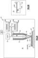
- Figures 2A-2C disclose a system which might be utilized to repair the Figure 1A/1B component.
- the additive manufacturing device 24 may be configured as a laser material deposition device, and may be called a direct laser braze cladding machine.
- a component support 28 supports a component 20 to be repaired.
- a pair of material reservoirs 30A and 30B are provided, as is a nozzle 32, a laser 34 and a material regulation device 36, all within an internal build chamber 38.
- the first material reservoir 30A stores a quantity of first braze powder 40A
- second material reservoir 30B stores a quantity of second braze powder 40B, to be supplied to the nozzle 32 through the material regulation device 36 during select additive manufacturing device operations.
- a control 100 is programmed to control material regulation device 36 to selectively direct the first braze powder 40A during a first mode, and selectively direct the second braze powder 40B during a second mode.
- the material regulation device 36 may also be controlled to selectively direct one or more combinations of the first braze powder 40A and the second braze powder 40B to the nozzle 32 during a third mode.
- the nozzle 32 is controlled to deliver a (e.g., annular, conical) stream 44 of the braze powder toward a substrate of component 20.
- a tubular inner sidewall 48 and a tubular outer sidewall 50 define passage 52 (e.g., an annulus) fluidly coupled (shown schematically) to material flow regulator 36, and extends to a nozzle orifice 54.
- a distal end portion of the nozzle 32 and its inner sidewall 48 and its outer sidewall 50 may radially taper inwards as the nozzle 32 extends axially toward nozzle orifice 54.
- the nozzle 32 may focus the braze powder 40 to, around or about a target point 56 on, slightly above or slightly below the substrate surface 42.
- nozzle 32 may be configured to deliver the braze powder 40 through an internal bore rather than an annulus.
- Control 100 is programmed to control laser 34 to generate a laser beam 58 for sintering the braze powder 40 delivered by the nozzle 32 to the substrate 42.
- sintering may describe a process for coalescing powder particles together into a solid coherent mass by heating without (e.g., partial or complete) liquification of the powder. This is in contrast to, for example, a powder laser welding process where powder is melted to a liquid state (e.g., in a melt pool) by a laser beam and then solidified as a solid mass.
- Laser 34 is controlled to direct the laser beam 58 to or about the target point 56 and heats the braze powder 40 for sintering.
- the laser beam 58 directed through an internal bore 60 of the nozzle 32 formed by the inner sidewall 48.
- the laser 34 may be configured to direct the laser beam 58 outside of the nozzle 32 or along another path through the nozzle 32.
- the first braze powder 40A may be deposited on the component 20 to repair a first type of substrate defect such as, but not limited to, the void 22.
- the second braze powder 40B may be deposited with the component 20 to repair a second type of substrate defect such as, but not limited to, the wear region 124 of Figures 1A and Figure 1B .
- the first braze powder 40A may be provided (e.g., selected, formulated, etc.) for increased wettability, flowability and/or capillary penetration.
- the first braze powder may thereby be particularly suited for entering and filling voids.
- the second braze powder 40B may be provided (e.g., selected, formulated, etc.) for improved dimensional repair of the surface due to lower wettability and flowability.
- the second braze powder may thereby be particularly suited for forming claddings.
- the first braze powder 40A and the second braze powder 40B may be mixed together in some proportion to provide a combined braze powder with intermediate braze properties.
- the two powders could be mixed might be to achieve various proportions of the two.
- a designer might want a high-flow, a moderate-flow or a stiff final deposited powder.
- the second braze powder 40B may include higher proportions of the metal alloy powder relative to the braze material powder (e.g., 70/30).
- the first braze powder 40A may include lower proportions of the metal alloy powder relative to the braze material powder (e.g., 30/70).
- the first braze powder 40A may include a mixture of metal alloy powder (e.g., substrate powder) and braze material powder.
- the metal alloy powder may be selected to have a relatively high melting point and common or similar material properties as the substrate of component 20, e.g., an aluminum (Al) superalloy, a nickel (Ni) superalloy, a titanium (Ti) superalloy, etc.
- the braze material powder may be selected to have a relatively low melting point, which is lower than the melting point of the metal alloy powder.
- the braze material powder may also include a common or similar base element as the substrate and/or the metal alloy powder (e.g., aluminum (Al), nickel (Ni) or titanium (Ti)) without the super alloying elements.
- the braze material powder may also include boron (B), silicon (Si) and/or other melting point suppressants which may help facilitate melting and diffusion of the metal alloy powder with the substrate.
- B boron
- Si silicon
- present disclosure is not limited to the foregoing exemplary braze materials.
- the second braze powder 40B may include a mixture of the metal alloy powder (e.g., substrate powder) and the braze material powder.
- a ratio of the metal alloy powder to the braze material powder in the second braze powder 40B may be greater than a ratio of the metal alloy powder to the braze material powder in the first braze powder 40A.
- the second braze powder 40B may include higher proportions of the metal alloy powder relative to the braze material powder (e.g., 60/40).
- the first braze powder 40A may include lower proportions of the metal alloy powder relative to the braze material powder (e.g., 30/70).
- the present disclosure is not limited to the foregoing exemplary braze powder makeups. In other embodiments, one or more or all of the constituent materials in the first braze powder may be different that one or more or all of the constituent materials in the second braze powder.
- the additive manufacturing device 24 of Figure 2A may dispose the respective braze powder 40 onto the substrate 42 at or about the target point 56.
- the laser 34 may concurrently sinter this respective braze powder 40 at the target point 56 together and/or to the underlying substrate 42.
- the additive manufacturing device 24 may selectively deposit the first braze powder and/or the second braze powder over the substrate such that areas which need repair, and optionally areas adjacent and/or surrounding those areas, are filled with the sintered first braze material 62A and/or coated with the sintered second braze material 62B.
- the first braze powder and/or the second braze powder may be deposited over an entirety of the substrate 42 and excess material may later be removed.
- the braze powders may be deposited as one or more layers.
- a furnace 26 is configured to receive the component 20 with the sintered first braze material 62A and/or the sintered second braze material 62B within furnace 26.
- the furnace 26 subjects the component and the sintered braze material 62A and 62B to a heat cycle, for example under vacuum and/or in a partial pressure inert gas (e.g., argon (Ar) gas) environment.
- a partial pressure inert gas e.g., argon (Ar) gas
- the sintered braze material(s) 62 may melt and diffusion bond to the substrate 42.
- An example of the furnace 26 is a vacuum furnace.
- the furnace temperature is selected such that the sintered braze materials 62A and 62B melts, wets and flows into defects of the substrate by capillary action.
- a relatively lower temperature may be selected and held in the same heat cycle for a duration. This sustained temperature may facilitate diffusion of the melting point suppressant material, and athermal solidification, resulting in a braze diffusion bond of the sintered material to the substrate.
- the diffusion duration may be between four (4) hours and twelve (12) hours. This elevated temperature, however, is less than a melting point temperature of the substrate material.
- the elevated temperature for the braze melt may be between 1,500°F (816°C) and 2,500°F (1371°C), and may be between 1,000°F (538°C) and 2,400°F (1316°C).
- the inert gas environment may have a vacuum pressure range between, for example, 0.5 microns (0.066 Pa) and 0.1 microns (0.013 Pa).
- the foregoing heat cycle parameters may vary depending upon the specific material composition of the substrate and the braze material, dimensions (e.g., thickness) of the sintered braze materials 62A and 62B, etc.
- first braze filler material 62A may partially or completely fill the void 22.
- the second braze filler material 62B may provide a cladding over the substrate 42 to restore a dimensional parameter of and/or reinforce the wear region 124 and/or other regions.
- Figure 2C shows an overall system 99 having a controller 100 controlling the additive manufacturing device 24, and a machining device 102, as will be explained below.
- the component 20 may be scanned by scanning device 103, which may be a computed tomography (CT) scan.
- CT computed tomography
- a CT scan takes a series of x-ray images taken from different angles around the component 20.
- an x-ray machine 104 is shown schematically with a guide 105 for allowing the x-ray machine to move to different angles relative to the component 20.
- Processing device 72 may operate as known to build the images.
- a memory 74 may be associated with historic manufacturing device for the component 20.
- the component may alternatively move relative to the x-ray machine.
- the scanning device may be a flat-panel volumetric CT or conventional multidetector CT scanner.
- the flat-panel detector has wide z-axis coverage that enables imagine of entire object in one axial acquisition.
- the scanning device 103 in conjunction with processing device 72, can map the component.
- Controller 100 may be implemented with a combination of hardware and software.
- the hardware may include at least the processing device 72 and the memory 74.
- the processing device 72 may include single-core and/or multi-core processors.
- the memory 74 is configured to store software or execution by the processing device. The software execution may control and/or facilitate performance of the several operations described in this application.
- the memory 74 may be a non-transitory computer readable medium. As an example, the memory 74 can be configured to include a volatile memory and/or a non-volatile memory.
- the scanning device in combination with a controller 100, is thus able to identify a surface geometry of the component, and to map spatial coordinates for at least a portion (or the entirety) of the component 20. Such mapping would identify dimensions and location of features such as the void 22, and the wear area 124.
- the scanned data may be in the form of a computer aided design model file, such as a stereolithography model file.
- Controller 100 may compare the mapped substrate characteristics from the scanned data with respective characteristics from reference data.
- the reference data may be data input from an OEM design specification for the component 20. In other words, the controller 100 may compare the mapped characteristics from the scan of the current component 20 being worked on to corresponding characteristics of the design specification.
- the controller 100 may generate a solid model of the scan data to compare to a solid model of a design space component.
- the controller 100 thereby evaluates the current state and condition of the component 20 and determines what additive operations need to be performed. Among the determined operations could be the amount of additive manufacturing materials to be deposited, which type, where to deposit the additive manufacturing materials, paths to follow for depositing of the additive manufacturing materials, all to put the component back to being closer to the design space.
- FIG. 3 A flowchart of a method according to this disclosure is illustrated in Figure 3 .
- the flowchart should be studied in combination with Figures 4, 5, 6, 7A, 7B, 8 and 9 .
- the component 20 to be repaired is as shown in Figure 1B .
- this component is provided for repair.
- step 404 the component is then prepared for additive manufacturing repair. Any number of steps may be performed as known to prepare the component. One such step is shown in Figure 4 with a tool 101 removing the residual coating 27. Other known preparation steps may also be taken.
- the component 20 is scanned.
- the scanning device 103 is shown with the x-ray machine 104 movable about the surface of the component in guide 105. As mentioned above, the part may alternatively move relative to the x-ray machine.
- the scanned data may be aligned with reference data such as a design specification of the component or an OEM model. Because the vane may have shifted during an engine heat cycle, the individual surface of the model vanes are broken apart and aligned to the substrate model from the scan. This creates a unique geometry to correct the performance of the part without returning the part to the original casting. This unique geometry represents a desired component file. Steps may further include importing pre-braze data, reverse engineered surfacing and subsequent toolpath generation. The substrate model is essentially what the part to be repaired is now.
- step 408 the data from the scan is provided to the controller 100, and the additive manufacturing tool path is determined based upon the scan.
- the desired component file is what is essentially compared to the substrate model.
- the additive manufacturing tool 24 now applies the first material 62A to the void 22.
- the additive manufacturing tool is shown supplying a second material 62B to the worn area 124.
- additional material 125 which has been deposited which is not desired on the final repaired component.
- material 123 which is desirably left and additional material 125 which is desirably removed.
- the additive manufacturing machine applies material with an over application percentage to allow the following subtractive process to be successful.
- material with an over application percentage to allow the following subtractive process to be successful.
- the additive system may add an extra 50 percent. This results in 0.03 inch (0.76 mm) of centered buildup. After diffusion, the material may only have 0.025 inch (0.64 mm) remaining. Leaving 0.005 inch (0.13 mm) for the subtractive machining process to achieve the correct result.
- the scanned data 106 and an estimate 108 of the additive material having been added are utilized in the controller 100 to determine the amount of material which is to be subtracted or removed from the intermediate component.
- step 412 a tool path is determined for removing the material 125 such that repaired component will approach its original state. Machining data will be developed in the controller 100 based upon the step 412 data.
- the AM data is aligned to the substrate model.
- the result is then compared to reference data (e.g. the desired component file) and the subtractive machining toolpath is determined.
- a tool 102 may remove the additional material as shown.
- an outer coating 73 could be added to the repaired component 20.
- Examples of the machining tools 101 and 102 may be any number of known material removable tools controlled to be movable about any number of axes.
- the reference data used to develop the AM path and the machining path may be the same file or could include two distinct files. While specific reference data sets are mentioned, other data sets can be used.
Landscapes
- Engineering & Computer Science (AREA)
- Chemical & Material Sciences (AREA)
- Materials Engineering (AREA)
- Manufacturing & Machinery (AREA)
- Physics & Mathematics (AREA)
- Mechanical Engineering (AREA)
- Optics & Photonics (AREA)
- Plasma & Fusion (AREA)
- Health & Medical Sciences (AREA)
- Analytical Chemistry (AREA)
- Biochemistry (AREA)
- Life Sciences & Earth Sciences (AREA)
- General Physics & Mathematics (AREA)
- Immunology (AREA)
- Pathology (AREA)
- Theoretical Computer Science (AREA)
- Radiology & Medical Imaging (AREA)
- General Health & Medical Sciences (AREA)
- Pulmonology (AREA)
- Nuclear Medicine, Radiotherapy & Molecular Imaging (AREA)
- Composite Materials (AREA)
- Automation & Control Theory (AREA)
- General Engineering & Computer Science (AREA)
- Powder Metallurgy (AREA)
- Analysing Materials By The Use Of Radiation (AREA)
Applications Claiming Priority (2)
| Application Number | Priority Date | Filing Date | Title |
|---|---|---|---|
| US18/108,132 US20240269747A1 (en) | 2023-02-10 | 2023-02-10 | Adaptive overhaul using structured light single data set |
| US18/116,559 US20240269748A1 (en) | 2023-02-10 | 2023-03-02 | Adaptive overhaul using ct scan single data set |
Publications (1)
| Publication Number | Publication Date |
|---|---|
| EP4414101A1 true EP4414101A1 (de) | 2024-08-14 |
Family
ID=89900968
Family Applications (1)
| Application Number | Title | Priority Date | Filing Date |
|---|---|---|---|
| EP24157193.4A Pending EP4414101A1 (de) | 2023-02-10 | 2024-02-12 | Adaptives overhaul unter verwendung eines ct-scan-einzeldatensatzes |
Country Status (3)
| Country | Link |
|---|---|
| US (1) | US20240269748A1 (de) |
| EP (1) | EP4414101A1 (de) |
| CA (1) | CA3223443A1 (de) |
Citations (4)
| Publication number | Priority date | Publication date | Assignee | Title |
|---|---|---|---|---|
| US20070163115A1 (en) * | 2006-01-16 | 2007-07-19 | United Technologies Corporation | Turbine platform repair using laser clad |
| US20120179285A1 (en) * | 2009-08-20 | 2012-07-12 | Torsten Melzer-Jokisch | Automated repair method and system |
| WO2019177607A1 (en) * | 2018-03-15 | 2019-09-19 | Siemens Energy, Inc. | Laser braze wire additive manufacturing of a super solutioned turbine blade component with subzero cooling |
| US20220212296A1 (en) * | 2019-07-30 | 2022-07-07 | Siemens Energy, Inc. | System and method for repairing high-temperature gas turbine blades |
Family Cites Families (3)
| Publication number | Priority date | Publication date | Assignee | Title |
|---|---|---|---|---|
| DE102015219345A1 (de) * | 2015-10-07 | 2017-04-13 | Siemens Aktiengesellschaft | Bauteil und schichtweise Auffüllung einer Fehlstelle mittels Lot- und Grundwerkstoff |
| US20190193156A1 (en) * | 2017-12-09 | 2019-06-27 | Linbo Yang | Simultaneous 3D printing and NDT with Computer Tomography using LDA |
| EP3933527A1 (de) * | 2020-07-03 | 2022-01-05 | Siemens Aktiengesellschaft | Verfahren und anordnung zum reparieren eines werkstücks |
-
2023
- 2023-03-02 US US18/116,559 patent/US20240269748A1/en active Pending
- 2023-12-15 CA CA3223443A patent/CA3223443A1/en active Pending
-
2024
- 2024-02-12 EP EP24157193.4A patent/EP4414101A1/de active Pending
Patent Citations (4)
| Publication number | Priority date | Publication date | Assignee | Title |
|---|---|---|---|---|
| US20070163115A1 (en) * | 2006-01-16 | 2007-07-19 | United Technologies Corporation | Turbine platform repair using laser clad |
| US20120179285A1 (en) * | 2009-08-20 | 2012-07-12 | Torsten Melzer-Jokisch | Automated repair method and system |
| WO2019177607A1 (en) * | 2018-03-15 | 2019-09-19 | Siemens Energy, Inc. | Laser braze wire additive manufacturing of a super solutioned turbine blade component with subzero cooling |
| US20220212296A1 (en) * | 2019-07-30 | 2022-07-07 | Siemens Energy, Inc. | System and method for repairing high-temperature gas turbine blades |
Also Published As
| Publication number | Publication date |
|---|---|
| CA3223443A1 (en) | 2025-04-29 |
| US20240269748A1 (en) | 2024-08-15 |
Similar Documents
| Publication | Publication Date | Title |
|---|---|---|
| US12115598B2 (en) | Adaptive overhaul using plural scanning methods | |
| US12251757B2 (en) | Adaptively depositing braze material(s) using CT scan data | |
| US20240082939A1 (en) | Adaptively depositing braze material using structured light scan data | |
| US20250345856A1 (en) | Adaptive manufacturing using ct scan data | |
| US12296400B2 (en) | Additively depositing multiple braze materials | |
| EP4424457A2 (de) | Adaptiver reparatur mit zwei lötmaterialien und strukturierten lichtscans | |
| JP2025090512A (ja) | 部品の補修のための低ポロシティ領域を有する多孔質金属クーポン、同クーポンを有する部品並びに関連方法 | |
| US20240269748A1 (en) | Adaptive overhaul using ct scan single data set | |
| EP4424458A2 (de) | Adaptiver reparatur mit zwei lötmaterialien und ct-scans | |
| EP4414102A1 (de) | Adaptives overhaul mit strukturiertem licht eines einzigen datensatzes | |
| EP4414103A1 (de) | Adaptive herstellung unter verwendung einer ct-abtastung und eines adaptiven herstellungswerkzeugpfades | |
| EP4335573A1 (de) | Adaptive herstellung unter verwendung von strukturierten lichtdaten | |
| EP4414100A1 (de) | Adaptive herstellung unter verwendung einer adaptiven herstellungswerkzeugbahn | |
| US20240085350A1 (en) | Adaptive manufacturing using ct scan data | |
| WO2015057304A1 (en) | Panel with cooling holes and methods for fabricating same | |
| US20240293864A1 (en) | Manufacturing component using high and low melt braze | |
| US20240082940A1 (en) | Additively depositing braze material | |
| EP4494795A1 (de) | Elektronenstrahlhartlöten zur reparatur einer komponente | |
| JP2025124586A (ja) | 金属部品又はそのクーポンにろう貯蔵部を設ける方法 | |
| JP2025121844A (ja) | 部品用のろう貯蔵部を有する金属クーポン、同金属クーポンを有する部品並びに関連方法 |
Legal Events
| Date | Code | Title | Description |
|---|---|---|---|
| PUAI | Public reference made under article 153(3) epc to a published international application that has entered the european phase |
Free format text: ORIGINAL CODE: 0009012 |
|
| STAA | Information on the status of an ep patent application or granted ep patent |
Free format text: STATUS: THE APPLICATION HAS BEEN PUBLISHED |
|
| AK | Designated contracting states |
Kind code of ref document: A1 Designated state(s): AL AT BE BG CH CY CZ DE DK EE ES FI FR GB GR HR HU IE IS IT LI LT LU LV MC ME MK MT NL NO PL PT RO RS SE SI SK SM TR |
|
| STAA | Information on the status of an ep patent application or granted ep patent |
Free format text: STATUS: REQUEST FOR EXAMINATION WAS MADE |
|
| 17P | Request for examination filed |
Effective date: 20250214 |