EP4414056A1 - Hollow fiber membrane module - Google Patents
Hollow fiber membrane module Download PDFInfo
- Publication number
- EP4414056A1 EP4414056A1 EP22878156.3A EP22878156A EP4414056A1 EP 4414056 A1 EP4414056 A1 EP 4414056A1 EP 22878156 A EP22878156 A EP 22878156A EP 4414056 A1 EP4414056 A1 EP 4414056A1
- Authority
- EP
- European Patent Office
- Prior art keywords
- hollow fiber
- case
- fiber membrane
- membrane module
- channel
- Prior art date
- Legal status (The legal status is an assumption and is not a legal conclusion. Google has not performed a legal analysis and makes no representation as to the accuracy of the status listed.)
- Pending
Links
Images


Classifications
-
- B—PERFORMING OPERATIONS; TRANSPORTING
- B01—PHYSICAL OR CHEMICAL PROCESSES OR APPARATUS IN GENERAL
- B01D—SEPARATION
- B01D63/00—Apparatus in general for separation processes using semi-permeable membranes
- B01D63/02—Hollow fibre modules
-
- B—PERFORMING OPERATIONS; TRANSPORTING
- B01—PHYSICAL OR CHEMICAL PROCESSES OR APPARATUS IN GENERAL
- B01D—SEPARATION
- B01D53/00—Separation of gases or vapours; Recovering vapours of volatile solvents from gases; Chemical or biological purification of waste gases, e.g. engine exhaust gases, smoke, fumes, flue gases, aerosols
- B01D53/22—Separation of gases or vapours; Recovering vapours of volatile solvents from gases; Chemical or biological purification of waste gases, e.g. engine exhaust gases, smoke, fumes, flue gases, aerosols by diffusion
- B01D53/228—Separation of gases or vapours; Recovering vapours of volatile solvents from gases; Chemical or biological purification of waste gases, e.g. engine exhaust gases, smoke, fumes, flue gases, aerosols by diffusion characterised by specific membranes
-
- B—PERFORMING OPERATIONS; TRANSPORTING
- B01—PHYSICAL OR CHEMICAL PROCESSES OR APPARATUS IN GENERAL
- B01D—SEPARATION
- B01D53/00—Separation of gases or vapours; Recovering vapours of volatile solvents from gases; Chemical or biological purification of waste gases, e.g. engine exhaust gases, smoke, fumes, flue gases, aerosols
- B01D53/26—Drying gases or vapours
- B01D53/268—Drying gases or vapours by diffusion
-
- B—PERFORMING OPERATIONS; TRANSPORTING
- B01—PHYSICAL OR CHEMICAL PROCESSES OR APPARATUS IN GENERAL
- B01D—SEPARATION
- B01D63/00—Apparatus in general for separation processes using semi-permeable membranes
- B01D63/02—Hollow fibre modules
- B01D63/04—Hollow fibre modules comprising multiple hollow fibre assemblies
-
- B—PERFORMING OPERATIONS; TRANSPORTING
- B01—PHYSICAL OR CHEMICAL PROCESSES OR APPARATUS IN GENERAL
- B01D—SEPARATION
- B01D63/00—Apparatus in general for separation processes using semi-permeable membranes
- B01D63/02—Hollow fibre modules
- B01D63/04—Hollow fibre modules comprising multiple hollow fibre assemblies
- B01D63/043—Hollow fibre modules comprising multiple hollow fibre assemblies with separate tube sheets
-
- B—PERFORMING OPERATIONS; TRANSPORTING
- B01—PHYSICAL OR CHEMICAL PROCESSES OR APPARATUS IN GENERAL
- B01D—SEPARATION
- B01D69/00—Semi-permeable membranes for separation processes or apparatus characterised by their form, structure or properties; Manufacturing processes specially adapted therefor
- B01D69/08—Hollow fibre membranes
-
- H—ELECTRICITY
- H01—ELECTRIC ELEMENTS
- H01M—PROCESSES OR MEANS, e.g. BATTERIES, FOR THE DIRECT CONVERSION OF CHEMICAL ENERGY INTO ELECTRICAL ENERGY
- H01M8/00—Fuel cells; Manufacture thereof
- H01M8/04—Auxiliary arrangements, e.g. for control of pressure or for circulation of fluids
- H01M8/04082—Arrangements for control of reactant parameters, e.g. pressure or concentration
- H01M8/04089—Arrangements for control of reactant parameters, e.g. pressure or concentration of gaseous reactants
- H01M8/04119—Arrangements for control of reactant parameters, e.g. pressure or concentration of gaseous reactants with simultaneous supply or evacuation of electrolyte; Humidifying or dehumidifying
- H01M8/04126—Humidifying
- H01M8/04149—Humidifying by diffusion, e.g. making use of membranes
-
- B—PERFORMING OPERATIONS; TRANSPORTING
- B01—PHYSICAL OR CHEMICAL PROCESSES OR APPARATUS IN GENERAL
- B01D—SEPARATION
- B01D53/00—Separation of gases or vapours; Recovering vapours of volatile solvents from gases; Chemical or biological purification of waste gases, e.g. engine exhaust gases, smoke, fumes, flue gases, aerosols
- B01D53/22—Separation of gases or vapours; Recovering vapours of volatile solvents from gases; Chemical or biological purification of waste gases, e.g. engine exhaust gases, smoke, fumes, flue gases, aerosols by diffusion
- B01D2053/221—Devices
- B01D2053/223—Devices with hollow tubes
- B01D2053/224—Devices with hollow tubes with hollow fibres
-
- B—PERFORMING OPERATIONS; TRANSPORTING
- B01—PHYSICAL OR CHEMICAL PROCESSES OR APPARATUS IN GENERAL
- B01D—SEPARATION
- B01D2313/00—Details relating to membrane modules or apparatus
- B01D2313/04—Specific sealing means
-
- B—PERFORMING OPERATIONS; TRANSPORTING
- B01—PHYSICAL OR CHEMICAL PROCESSES OR APPARATUS IN GENERAL
- B01D—SEPARATION
- B01D2313/00—Details relating to membrane modules or apparatus
- B01D2313/08—Flow guidance means within the module or the apparatus
-
- B—PERFORMING OPERATIONS; TRANSPORTING
- B01—PHYSICAL OR CHEMICAL PROCESSES OR APPARATUS IN GENERAL
- B01D—SEPARATION
- B01D2313/00—Details relating to membrane modules or apparatus
- B01D2313/08—Flow guidance means within the module or the apparatus
- B01D2313/083—Bypass routes
-
- B—PERFORMING OPERATIONS; TRANSPORTING
- B01—PHYSICAL OR CHEMICAL PROCESSES OR APPARATUS IN GENERAL
- B01D—SEPARATION
- B01D2313/00—Details relating to membrane modules or apparatus
- B01D2313/20—Specific housing
- B01D2313/203—Open housings
-
- B—PERFORMING OPERATIONS; TRANSPORTING
- B01—PHYSICAL OR CHEMICAL PROCESSES OR APPARATUS IN GENERAL
- B01D—SEPARATION
- B01D2313/00—Details relating to membrane modules or apparatus
- B01D2313/26—Specific gas distributors or gas intakes
-
- Y—GENERAL TAGGING OF NEW TECHNOLOGICAL DEVELOPMENTS; GENERAL TAGGING OF CROSS-SECTIONAL TECHNOLOGIES SPANNING OVER SEVERAL SECTIONS OF THE IPC; TECHNICAL SUBJECTS COVERED BY FORMER USPC CROSS-REFERENCE ART COLLECTIONS [XRACs] AND DIGESTS
- Y02—TECHNOLOGIES OR APPLICATIONS FOR MITIGATION OR ADAPTATION AGAINST CLIMATE CHANGE
- Y02E—REDUCTION OF GREENHOUSE GAS [GHG] EMISSIONS, RELATED TO ENERGY GENERATION, TRANSMISSION OR DISTRIBUTION
- Y02E60/00—Enabling technologies; Technologies with a potential or indirect contribution to GHG emissions mitigation
- Y02E60/30—Hydrogen technology
- Y02E60/50—Fuel cells
Definitions
- the present invention relates to a hollow fiber membrane module.
- Hollow fiber membrane modules are provided in humidifiers that are used in automotive fuel cells.
- the size of hollow fiber membrane modules is tending to increase, with higher-output systems being demanded from such equipment. On the other hand, size reduction is called for, to address the issue of in-vehicle space.
- requirements in terms of humidification performance are being eased as the stack performance of fuel cells has improved, hollow fiber membrane modules in conventional structures nevertheless have to necessarily increase in size for the purpose of reducing pressure loss of dry gas and moist gas supplied to the hollow fiber membrane modules.
- Such a problem may arise not only in hollow fiber membrane modules in various humidifiers for fuel cells and others, but also in hollow fiber membrane modules used in dehumidifiers.
- the present invention provides a hollow fiber membrane module that allows reducing the pressure loss of dry gas and moist gas.
- the present invention relies on the following means to solve the above problem.
- the hollow fiber membrane module of the present invention has:
- the present invention allows reducing pressure loss of the first gas, since part of the first gas flows through the first channel without passing through the intra-membrane channels.
- pressure loss of the second gas can be reduced since part of the second gas flows through the second channel without passing through the extra-membrane channels.
- the housing interior may be divided into a plurality of sites by a partition wall, and the hollow fiber membrane bundle is thereby divisionally accommodated at the plurality of sites, the first channel being provided so as to run through the partition wall.
- the first channel may be provided so as to run through an outer wall of the case between an outer peripheral wall surface thereof and the housing interior.
- a tubular member of which both ends are respectively fixed by the pair of sealing and fixing parts, may be also provided in the housing interior, and a tubular interior of the tubular member may be the first channel.
- the housing interior may be divided into a plurality of sites by a partition wall, and the hollow fiber membrane bundle is thereby divisionally accommodated at the plurality of sites, the second channel being provided so as to run through the partition wall.
- the second channel may be provided so as to run through an outer wall of the case between an outer peripheral wall surface thereof and the housing interior.
- the present invention allows reducing pressure loss of a dry gas and of a moist gas.
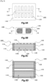
- FIG. 1 is a schematic configuration diagram of a hollow fiber membrane module according to Embodiment 1 of the present invention.
- Fig. 1(a) is a plan-view diagram of a hollow fiber membrane module
- Fig. 1(b) is a front-view diagram of the hollow fiber membrane module
- Fig. 1(c) is an A1-A1 cross-sectional diagram of Fig. 1(a)
- Fig. 1(d) is an A2-A2 cross-sectional diagram of Fig. 1(b) .
- a hollow fiber membrane module 100A includes a case 110A, a hollow fiber membrane bundle 120A made up of a plurality of hollow fiber membranes accommodated in the case 110A, and a pair of sealing and fixing parts 131A, 132A that fixes the hollow fiber membrane bundle 120A to the case 110A.
- the case 110A is made up of a cuboid-shaped tubular member.
- the hollow fiber membrane bundle 120A is accommodated in a housing interior 110IA such that both ends of the case 110A thus configured are open.
- the hollow fiber membrane module 100A according to the present embodiment can be used as a humidifier or a dehumidifier.
- a humidifier or a dehumidifier.
- the hollow fiber membrane module 100A has intra-membrane channels passing through the interior of the plurality of hollow fiber membranes that make up the hollow fiber membrane bundle 120A, and extra-membrane channels passing over the exterior of the hollow fiber membranes.
- the intra-membrane channels are configured so that a dry gas as a first gas flows from one end side of the case 110A, through the hollow interior of the plurality of hollow fiber membranes, to the other end side of the case 110A (see arrows R1 in Fig. 1(c) ).
- the extra-membrane channels are configured so that a moist gas as a second gas flows from inlets 113A formed in the case 110A, through the housing interior 110IA, to outlets 114A formed in the case 110A ( Fig. 1 (c) , see arrows R2).
- the moist gas is more humid than the dry gas.
- a plurality of through-holes provided in one of a pair of plate-like portions of the case 110A corresponds to respective inlets 113A, while a plurality of through-holes provided in the other of the pair of plate-like portions corresponds to respective outlets 114A.
- the hollow fiber membranes can be used as both a humidifier and a dehumidifier since dry gas is humidified and moist gas is dehumidified.
- the hollow fiber membrane module 100A can be suitably used as a humidifier for humidifying an electrolyte membrane that is provided in a fuel cell.
- moist air generated in the fuel cell is used as the moist gas.
- the electrolyte membrane is thus maintained in a moist state through supply of humidified gas (air) to the electrolyte membrane that is provided in the fuel cell.
- PPSU polyphenylsulfone
- Preparation of a membrane-forming solution involves performing spinning using a membrane-forming solution resulting from adding PPSU and a hydrophilic polymer (polyvinyl pyrrolidone) to a solvent, to obtain as a result a hydrophilic hollow fiber membrane.
- a hydrophilic polymer polyvinyl pyrrolidone
- Nafion registered trademark
- the above materials boast low elution properties and high strength, and accordingly can be suitably used in humidifiers and dehumidifiers.
- the hollow fiber membrane module 100A according to the present embodiment is provided with a first channel 115A running through from one end side to the other end side of the case 110A and through which part of the dry gas flows without passing through the housing interior 110IA.
- the first channel 115A is provided so that part of the dry gas flows therethrough without passing through the intra-membrane channels.
- This first channel 115A will be explained more specifically next.
- the housing interior 110IA of the case 110A according to the present embodiment is divided by a partition wall.
- the hollow fiber membrane bundle 120A is thus divided and accommodated at two sites.
- the first channel 115A is provided so as to run through the above partition wall.
- a configuration is depicted in which the housing interior 110IA is divided into two by one partition wall, but a configuration may be adopted in which the housing interior 110IA is divided into a plurality thereof by two or more partition walls. In that case the hollow fiber membrane bundle 120A is thus divided and accommodated at more sites.
- the first channel 115A can be provided in each partition wall.
- the hollow fiber membrane module 100A thus configured allows reducing pressure loss of the dry gas, since part of the dry gas flows through the first channel 115A without passing through the housing interior 110IA of the case 110A (in other words, without passing through the intra-membrane channels). As a result, this allows curtailing increases in the size of the hollow fiber membrane module 100A.
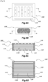
- FIG. 2 is a schematic configuration diagram of a hollow fiber membrane module according to Embodiment 2 of the present invention.
- Fig. 2(a) is a plan-view diagram of a hollow fiber membrane module
- Fig. 2(b) is a front-view diagram of the hollow fiber membrane module
- Fig. 2(c) is a B1-B1 cross-sectional diagram of Fig. 2(a)
- Fig. 2(d) is a B2-B2 cross-sectional diagram of Fig. 2(b) .
- a hollow fiber membrane module 100B includes a case 110B, a hollow fiber membrane bundle 120B made up of a plurality of hollow fiber membranes accommodated in the case 110B, and a pair of sealing and fixing parts 131B, 132B that fixes the hollow fiber membrane bundle 120B to the case 110B.
- the case 110B is made up of a cuboid-shaped tubular member.
- the hollow fiber membrane bundle 120B is accommodated in a housing interior 110IB such that both ends of the case 110B thus configured are open.
- the hollow fiber membrane module 100B according to the present embodiment can be used as a humidifier or a dehumidifier.
- the flow of dry gas and moist gas when the hollow fiber membrane module 100B is used as a humidifier or dehumidifier is as explained in Embodiment 1. That is, the intra-membrane channels are configured so that a dry gas flows from one end side of the case 110B, through the hollow interior of the plurality of hollow fiber membranes, to the other end side of the case 110B.
- the extra-membrane channels are configured so that a moist gas flows from inlets 113B formed in the case 110B, through the housing interior 110IB, to outlets formed in the case 110B.
- a plurality of through-holes provided in one of a pair of plate-like portions of the case 110B corresponds to respective inlets 113B, and a plurality of through-holes (not shown) provided in the other of the pair of plate-like portions corresponds to respective outlets.
- Embodiment 1 The humidification and dehumidification mechanisms elicited by the membrane separation effect are as explained concerning Embodiment 1.
- the hollow fiber membrane module 100B according to the present embodiment can be suitably used as a humidifier for humidifying an electrolyte membrane that is provided in a fuel cell.
- the hollow fiber membrane module 100B is provided with a first channel 115B running through from one end side to the other end side of the case 110B and through which part of the dry gas flows without passing through the housing interior 110IB.
- the first channel 115B is provided so that part of the dry gas flows therethrough without passing through the intra-membrane channels.
- This first channel 115B will be explained more specifically next.
- This first channel 115B is provided so as to run through an outer wall of the case 110B between the outer peripheral wall surface thereof and the housing interior 110IB.
- first channel 115B is provided at the width-direction center of a plate-like portion in which the plurality of inlets 113B is provided, but the position at which the first channel 115B is provided is not particularly limited.
- a configuration can also be adopted in which a plurality of first channels 115B is provided.
- the hollow fiber membrane module 100B thus configured allows reducing pressure loss of the dry gas, since part of the dry gas flows through the first channel 115B without passing through the housing interior 110IB of the case 110B (in other words, without passing through the intra-membrane channels). As a result, this allows curtailing increases in the size of the hollow fiber membrane module 100B.
- FIG. 3 is a schematic configuration diagram of a hollow fiber membrane module according to Embodiment 3 of the present invention.
- Fig. 3(a) is a plan-view diagram of a hollow fiber membrane module
- Fig. 3(b) is a front-view diagram of the hollow fiber membrane module
- Fig. 3(c) is a C1-C1 cross-sectional diagram of Fig. 3(a)
- Fig. 3(d) is a C2-C2 cross-sectional diagram of Fig. 3(b) .
- a hollow fiber membrane module 100C includes a case 110C, a hollow fiber membrane bundle 120C made up of a plurality of hollow fiber membranes accommodated in the case 110C, and pair of sealing and fixing parts 131C, 132C that fixes the hollow fiber membrane bundle 120C to the case 110C.
- the case 110C is made up of a cuboid-shaped tubular member.
- the hollow fiber membrane bundle 120C is accommodated in a housing interior 110IC such that both ends of the case 110C thus configured are open.
- the hollow fiber membrane module 100C according to the present embodiment can be used as a humidifier or a dehumidifier.
- the flow of dry gas and moist gas when the hollow fiber membrane module 100C is used as a humidifier or dehumidifier is as explained in Embodiment 1. That is, the intra-membrane channels are configured so that a dry gas flows from one end side of the case 110C, through the hollow interior of the plurality of hollow fiber membranes, to the other end side of the case 110C.
- the extra-membrane channels are configured so that a moist gas flows from inlets 113C formed in the case 110C, through the housing interior 110IC, to outlets 114C formed in the case 110C.
- a plurality of through-holes provided in one of a pair of plate-like portions of the case 110C corresponds to respective inlets 113C, and a plurality of through-holes provided in the other of the pair of plate-like portions corresponds to respective outlets 114C.
- Embodiment 1 The humidification and dehumidification mechanisms elicited by the membrane separation effect are as explained concerning Embodiment 1.
- the hollow fiber membrane module 100C according to the present embodiment can be suitably used as a humidifier for humidifying an electrolyte membrane that is provided in a fuel cell.
- the hollow fiber membrane module 100C is provided with a first channel 115C running through from one end side to the other end side of the case 110C and through which part of the dry gas flows without passing through the housing interior 110IC.
- the first channel 115C is provided so that part of the dry gas flows therethrough without passing through the intra-membrane channels.
- This first channel 115C will be explained more specifically next.
- This first channel 115C is provided so as to run through an outer wall of the case 110C between the outer peripheral wall surface thereof and the housing interior 110IC. In the present embodiment an instance is illustrated in which the first channel 115C is provided on both sides of the housing interior 110IC in the width direction, but a configuration may also be adopted in which the first channel 115C is provided on one side alone.
- the hollow fiber membrane module 100C thus configured allows reducing pressure loss of the dry gas, since part of the dry gas flows through the first channel 115C without passing through the housing interior 110IC of the case 110C (in other words, without passing through the intra-membrane channels. As a result, this allows curtailing increases in the size of the hollow fiber membrane module 100C.
- FIG. 4 is a schematic configuration diagram of a hollow fiber membrane module according to Embodiment 4 of the present invention.
- Fig. 4(a) is a plan-view diagram of a hollow fiber membrane module
- Fig. 4(b) is a front-view diagram of the hollow fiber membrane module
- Fig. 4(c) is a D1-D1 cross-sectional diagram of Fig. 4(a)
- Fig. 4(d) is a D2-D2 cross-sectional diagram of Fig. 4(b) .
- a hollow fiber membrane module 100D includes a case 110D, a hollow fiber membrane bundle 120D made up of a plurality of hollow fiber membranes accommodated in the case 110D, and a pair of sealing and fixing parts 131D, 132D that fixes the hollow fiber membrane bundle 120D to the case 110D.
- the case 110D is made up of a cuboid-shaped tubular member.
- the hollow fiber membrane bundle 120D is accommodated in a housing interior 110ID such that both ends of the case 110D thus configured are open.
- the hollow fiber membrane module 100D can be used as a humidifier or a dehumidifier.
- the flow of dry gas and moist gas when the hollow fiber membrane module 100D is used as a humidifier or dehumidifier is as explained in Embodiment 1. That is, the intra-membrane channels are configured so that a dry gas flows from one end side of the case 110D, through the hollow interior of the plurality of hollow fiber membranes, to the other end side of the case 110D.
- the extra-membrane channels are configured so that a moist gas flows from inlets 113D formed in the case 110D, through the housing interior 110ID, to outlets 114D formed in the case 110D.
- a plurality of through-holes provided in one of a pair of plate-like portions of the case 110D corresponds to respective inlets 113D, and a plurality of through-holes provided in the other of the pair of plate-like portions corresponds to respective outlets 114D.
- Embodiment 1 The humidification and dehumidification mechanisms elicited by the membrane separation effect are as explained concerning Embodiment 1.
- the hollow fiber membrane module 100D according to the present embodiment can be suitably used as a humidifier for humidifying an electrolyte membrane that is provided in a fuel cell.
- first channels 115D running through from one end side to the other end side of the case 110D and through which part of the dry gas flows without passing through the intra-membrane channels.
- This first channels 115D will be explained more specifically next.
- tubular members disposed in the housing interior 110ID of the case 110D such that both ends of each tubular member are fixed by the pair of sealing and fixing parts 131D, 132D.
- the interiors of these tubular members correspond to the first channels 115D.
- the hollow fiber membrane module 100D thus configured allows reducing pressure loss of the dry gas, since part of the dry gas flows through the first channels 115D without passing through the intra-membrane channels. As a result, this allows curtailing increases in the size of the hollow fiber membrane module 100D.
- FIG. 5 is a schematic configuration diagram of a hollow fiber membrane module according to Embodiment 5 of the present invention.
- Fig. 5(a) is a plan-view diagram of a hollow fiber membrane module
- Fig. 5(b) is a front-view diagram of the hollow fiber membrane module
- Fig. 5(c) is an E1-E1 cross-sectional diagram of Fig. 5(a)
- Fig. 5(d) is an E2-E2 cross-sectional diagram of Fig. 5(b) .
- the hollow fiber membrane module 100E includes a case 110E, a hollow fiber membrane bundle 120E made up of a plurality of hollow fiber membranes accommodated in the case 110E, and a pair of sealing and fixing parts 131E, 132E that fixes the hollow fiber membrane bundle 120E to the case 110E.
- the case 110E is made up of a cuboid-shaped tubular member.
- the hollow fiber membrane bundle 120E is accommodated in a housing interior 110IE such that both ends of the case 110E thus configured are open.
- the hollow fiber membrane module 100E according to the present embodiment can be used as a humidifier or a dehumidifier.
- the flow of dry gas and moist gas when the hollow fiber membrane module 100E is used as a humidifier or dehumidifier is as explained in Embodiment 1. That is, the intra-membrane channels are configured so that a dry gas flows from one end side of the case 110E, through the hollow interior of the plurality of hollow fiber membranes, to the other end side of the case 110E.
- the extra-membrane channels are configured so that a moist gas flows from inlets 113E formed in the case 110E, through the housing interior 110IE, to outlets 114E formed in the case 110E.
- a plurality of through-holes provided in one of a pair of plate-like portions of the case 110E corresponds to respective inlets 113E, and a plurality of through-holes provided in the other of the pair of plate-like portions corresponds to respective outlets 114E.
- Embodiment 1 The humidification and dehumidification mechanisms elicited by the membrane separation effect are as explained concerning Embodiment 1.
- the hollow fiber membrane module 100E according to the present embodiment can be suitably used as a humidifier for humidifying an electrolyte membrane that is provided in a fuel cell.
- a second channel 115E that runs through the case 110E in a direction that intersects a direction from one end side towards the other end side of the case 110E, such that part of the moist gas flows through the second channel 115E without passing through the housing interior 110IE. That is, the second channel 115E is provided so that part of the moist gas flows therethrough but without passing through the extra-membrane channels.
- the second channel 115E will be explained more specifically next.
- the housing interior 110IE of the case 110E according to the present embodiment is divided by a partition wall.
- the hollow fiber membrane bundle 120E is thus divided and accommodated at two sites.
- the second channel 115E is provided so as to run through the above partition wall.
- a configuration is depicted in which the housing interior 110IE is divided into two by one partition wall, but a configuration may be adopted in which the housing interior 110IE is divided into a plurality thereof by two or more partition walls. In that case the hollow fiber membrane bundle 120E is thus divided and accommodated at more sites.
- the second channel 115E can be provided in each partition wall.
- the hollow fiber membrane module 100E thus configured allows reducing pressure loss of the moist gas, since part of the moist gas flows through the second channel 115E without passing through the housing interior 110IE of the case 110E (in other words, without passing through the extra-membrane channels). As a result, this allows curtailing increases in the size of the hollow fiber membrane module 100E.
- FIG. 6 is a schematic configuration diagram of a hollow fiber membrane module according to Embodiment 6 of the present invention.
- Fig. 6(a) is a plan-view diagram of a hollow fiber membrane module
- Fig. 6(b) is a front-view diagram of the hollow fiber membrane module
- Fig. 6(c) is a F1-F1 cross-sectional diagram of Fig. 6(a)
- Fig. 6(d) is an F2-F2 cross-sectional diagram of Fig. 6(b) .
- a hollow fiber membrane module 100F includes a case 110F, a hollow fiber membrane bundle 120F made up of a plurality of hollow fiber membranes accommodated in the case 110F, and a pair of sealing and fixing parts 131F, 132F that fixes the hollow fiber membrane bundle 120F to the case 110F.
- the case 110F is made up of a cuboid-shaped tubular member.
- the hollow fiber membrane bundle 120F is accommodated in a housing interior 110IF such that both ends of the case 110F thus configured are open.
- the hollow fiber membrane module 100F can be used as a humidifier or a dehumidifier.
- the flow of dry gas and moist gas when the hollow fiber membrane module 100F is used as a humidifier or dehumidifier is as explained in Embodiment 1. That is, the intra-membrane channels are configured so that a dry gas flows from one end side of the case 110F, through the hollow interior of the plurality of hollow fiber membranes, to the other end side of the case 110F.
- the extra-membrane channels are configured so that a moist gas flows from inlets 113F formed in the case 110F, through the housing interior 110IF, to outlets 114F formed in the case 110F.
- a plurality of through-holes provided in one of a pair of plate-like portions of the case 110F corresponds to respective inlets 113F, and a plurality of through-holes provided in the other of the pair of plate-like portions corresponds to respective outlets 114F.
- Embodiment 1 The humidification and dehumidification mechanisms elicited by the membrane separation effect are as explained concerning Embodiment 1.
- the hollow fiber membrane module 100F according to the present embodiment can be suitably used as a humidifier for humidifying an electrolyte membrane that is provided in a fuel cell.
- a second channel 115F that runs through the case 110F in a direction that intersects a direction from one end side towards the other end side of the case 110F, such that part of the moist gas flows through the second channel 115F without passing through the housing interior 110IF. That is, the second channel 115F is provided so that part of the moist gas flows therethrough but without passing through the extra-membrane channels.
- the second channel 115F will be explained more specifically next.
- This second channel 115F is provided so as to run through an outer wall of the case 110F between the outer peripheral wall surface thereof and the housing interior 110IF. In the present embodiment an instance is illustrated in which the second channel 115F is provided on both sides of the housing interior 110IF in the width direction, but a configuration may also be adopted in which the second channel 115F is provided on one side alone.
- the hollow fiber membrane module 100F thus configured allows reducing pressure loss of the moist gas, since part of the moist gas flows through the second channel 115F without passing through the housing interior 110IF of the case 110F (in other words, without passing through the extra-membrane channels). As a result, this allows curtailing increases in the size of the hollow fiber membrane module 100E.
- a configuration resulting from combining two or more of the configurations illustrated in Embodiments 1 to 4 may be adopted in the first channel through which part of the dry gas flows without passing through the intra-membrane channels.
- a configuration resulting from combining the configurations illustrated in Embodiments 5 and 6 may be adopted in the second channel through which part of the moist gas flows without passing through the extra-membrane channels.
- a moist gas as a first gas flows through intra-membrane channels and a first channel
- a moist gas as a second gas flows through extra-membrane channels and a second channel
- a moist gas as a first gas may be set to flow through the intra-membrane channels and the first channel
- a dry gas as a second gas may be set to flow through the extra-membrane channels and the second channel.
- Embodiment 4 an instance has been illustrated in which the first channel is provided by providing a tubular member, whereas in the other embodiments the first channel is provided in the case itself. Adopting the latter approach is advantageous herein in terms of making it possible to reduce the number of parts and reduce costs in that mold costs incurred for instance in producing the tubular member are rendered unnecessary.
Landscapes
- Chemical & Material Sciences (AREA)
- Chemical Kinetics & Catalysis (AREA)
- Engineering & Computer Science (AREA)
- General Chemical & Material Sciences (AREA)
- Analytical Chemistry (AREA)
- Oil, Petroleum & Natural Gas (AREA)
- Life Sciences & Earth Sciences (AREA)
- Manufacturing & Machinery (AREA)
- Sustainable Development (AREA)
- Sustainable Energy (AREA)
- Electrochemistry (AREA)
- Separation Using Semi-Permeable Membranes (AREA)
- Fuel Cell (AREA)
Abstract
Description
- The present invention relates to a hollow fiber membrane module.
- Hollow fiber membrane modules are provided in humidifiers that are used in automotive fuel cells. The size of hollow fiber membrane modules is tending to increase, with higher-output systems being demanded from such equipment. On the other hand, size reduction is called for, to address the issue of in-vehicle space. Although requirements in terms of humidification performance are being eased as the stack performance of fuel cells has improved, hollow fiber membrane modules in conventional structures nevertheless have to necessarily increase in size for the purpose of reducing pressure loss of dry gas and moist gas supplied to the hollow fiber membrane modules. Such a problem may arise not only in hollow fiber membrane modules in various humidifiers for fuel cells and others, but also in hollow fiber membrane modules used in dehumidifiers.
- [PTL 1]
WO 2014/054740 - The present invention provides a hollow fiber membrane module that allows reducing the pressure loss of dry gas and moist gas.
- The present invention relies on the following means to solve the above problem.
- Specifically, the hollow fiber membrane module of the present invention has:
- a hollow fiber membrane bundle made up of a plurality of hollow fiber membranes;
- a case of which both ends are open and in a housing interior of which the hollow fiber membrane bundle is accommodated;
- a pair of sealing and fixing parts that seals respective openings at respective ends of the case in a state where a hollow interior of the hollow fiber membranes is left open and that fixes the hollow fiber membrane bundle to the case at one end side and another end side of the case;
- intra-membrane channels in which a first gas flows from one end side of the case to the other end side of the case through the hollow interior of the plurality of hollow fiber membranes; and
- extra-membrane channels in which a second gas flows from an inlet formed in the case to an outlet formed in the case through the housing interior,
- one of the first gas and the second gas being a dry gas and the other being a moist gas having higher humidity than that of the dry gas, whereby moisture in the moist gas is supplied into the dry gas by virtue of a membrane separation effect of the hollow fiber membranes,
- wherein at least one of a first channel and a second channel is provided, the first channel runs through the case from one end side to the other end side and in which part of the first gas flows without passing through the intra-membrane channels, and the second channel runs through the case in a direction that intersects a direction from the one end side to the other end side of the case and through which part of the second gas flows without passing through the extra-membrane channels.
- In a case where the first channel is provided, the present invention allows reducing pressure loss of the first gas, since part of the first gas flows through the first channel without passing through the intra-membrane channels. In a case where the second channel is provided, pressure loss of the second gas can be reduced since part of the second gas flows through the second channel without passing through the extra-membrane channels.
- The housing interior may be divided into a plurality of sites by a partition wall, and the hollow fiber membrane bundle is thereby divisionally accommodated at the plurality of sites, the first channel being provided so as to run through the partition wall.
- Preferably, the first channel may be provided so as to run through an outer wall of the case between an outer peripheral wall surface thereof and the housing interior.
- Preferably, a tubular member, of which both ends are respectively fixed by the pair of sealing and fixing parts, may be also provided in the housing interior, and a tubular interior of the tubular member may be the first channel.
- Preferably, the housing interior may be divided into a plurality of sites by a partition wall, and the hollow fiber membrane bundle is thereby divisionally accommodated at the plurality of sites, the second channel being provided so as to run through the partition wall.
- Preferably, the second channel may be provided so as to run through an outer wall of the case between an outer peripheral wall surface thereof and the housing interior.
- The above configurations may be combined with each other wherever possible.
- As explained above, the present invention allows reducing pressure loss of a dry gas and of a moist gas.
-
- [
Fig. 1 ]
Fig. 1 is a schematic configuration diagram of a hollow fiber membrane module according to Embodiment 1 of the present invention. - [
Fig. 2 ]
Fig. 2 is a schematic configuration diagram of a hollow fiber membrane module according to Embodiment 2 of the present invention. - [
Fig. 3 ]
Fig. 3 is a schematic configuration diagram of a hollow fiber membrane module according to Embodiment 3 of the present invention. - [
Fig. 4 ]
Fig. 4 is a schematic configuration diagram of a hollow fiber membrane module according to Embodiment 4 of the present invention. - [
Fig. 5 ]
Fig. 5 is a schematic configuration diagram of a hollow fiber membrane module according to Embodiment 5 of the present invention. - [
Fig. 6 ]
Fig. 6 is a schematic configuration diagram of a hollow fiber membrane module according to Embodiment 6 of the present invention. - Modes for carrying out the present invention will be illustratively explained in detail below on the basis of embodiments, with reference to accompanying drawings. Unless otherwise stated, however, the dimensions, materials, shapes, relative arrangements and so forth of the constituent elements described in the embodiments are not meant to limit the scope of the present invention to the foregoing alone.
- A hollow fiber membrane module according to Embodiment 1 of the present invention will be explained next with reference to
Fig. 1. Fig. 1 is a schematic configuration diagram of a hollow fiber membrane module according to Embodiment 1 of the present invention.Fig. 1(a) is a plan-view diagram of a hollow fiber membrane module,Fig. 1(b) is a front-view diagram of the hollow fiber membrane module,Fig. 1(c) is an A1-A1 cross-sectional diagram ofFig. 1(a), and Fig. 1(d) is an A2-A2 cross-sectional diagram ofFig. 1(b) . - A hollow
fiber membrane module 100A according to the present embodiment includes acase 110A, a hollowfiber membrane bundle 120A made up of a plurality of hollow fiber membranes accommodated in thecase 110A, and a pair of sealing andfixing parts fiber membrane bundle 120A to thecase 110A. Thecase 110A is made up of a cuboid-shaped tubular member. The hollowfiber membrane bundle 120A is accommodated in a housing interior 110IA such that both ends of thecase 110A thus configured are open. The pair of sealing andfixing parts case 110A, sealsrespective openings case 110A in a state where the hollow interior of the hollow fiber membranes is left open, and fixes the hollowfiber membrane bundle 120A to thecase 110A. - An application example of the hollow
fiber membrane module 100A according to the present embodiment will now be explained. The hollowfiber membrane module 100A according to the present embodiment can be used as a humidifier or a dehumidifier. Here follows a succinct explanation of this feature. - The hollow
fiber membrane module 100A has intra-membrane channels passing through the interior of the plurality of hollow fiber membranes that make up the hollowfiber membrane bundle 120A, and extra-membrane channels passing over the exterior of the hollow fiber membranes. In the present embodiment, the intra-membrane channels are configured so that a dry gas as a first gas flows from one end side of thecase 110A, through the hollow interior of the plurality of hollow fiber membranes, to the other end side of thecase 110A (see arrows R1 inFig. 1(c) ). The extra-membrane channels are configured so that a moist gas as a second gas flows frominlets 113A formed in thecase 110A, through the housing interior 110IA, tooutlets 114A formed in thecase 110A (Fig. 1 (c) , see arrows R2). The moist gas is more humid than the dry gas. A plurality of through-holes provided in one of a pair of plate-like portions of thecase 110A corresponds torespective inlets 113A, while a plurality of through-holes provided in the other of the pair of plate-like portions corresponds torespective outlets 114A. - By virtue of the above configuration, moisture in the moist gas migrates into the dry gas on account of the membrane separation effect of the hollow fiber membranes. Therefore, the hollow fiber membranes can be used as both a humidifier and a dehumidifier since dry gas is humidified and moist gas is dehumidified.
- The hollow
fiber membrane module 100A according to the present embodiment can be suitably used as a humidifier for humidifying an electrolyte membrane that is provided in a fuel cell. In that case moist air generated in the fuel cell is used as the moist gas. The electrolyte membrane is thus maintained in a moist state through supply of humidified gas (air) to the electrolyte membrane that is provided in the fuel cell. For instance, PPSU (polyphenylsulfone) having the property of allowing moisture to permeate thanks to a capillary condensation mechanism based on pore size control can be used as appropriate herein as the material of the hollow fiber membranes. Preparation of a membrane-forming solution (starting material of the hollow fiber membranes) involves performing spinning using a membrane-forming solution resulting from adding PPSU and a hydrophilic polymer (polyvinyl pyrrolidone) to a solvent, to obtain as a result a hydrophilic hollow fiber membrane. It is also possible to use Nafion (registered trademark), which is a hydrophilic material having the property of letting moisture through by dissolution and diffusion. The above materials boast low elution properties and high strength, and accordingly can be suitably used in humidifiers and dehumidifiers. - The hollow
fiber membrane module 100A according to the present embodiment is provided with afirst channel 115A running through from one end side to the other end side of thecase 110A and through which part of the dry gas flows without passing through the housing interior 110IA. Specifically, thefirst channel 115A is provided so that part of the dry gas flows therethrough without passing through the intra-membrane channels. Thisfirst channel 115A will be explained more specifically next. The housing interior 110IA of thecase 110A according to the present embodiment is divided by a partition wall. The hollowfiber membrane bundle 120A is thus divided and accommodated at two sites. Thefirst channel 115A is provided so as to run through the above partition wall. In the present embodiment a configuration is depicted in which the housing interior 110IA is divided into two by one partition wall, but a configuration may be adopted in which the housing interior 110IA is divided into a plurality thereof by two or more partition walls. In that case the hollowfiber membrane bundle 120A is thus divided and accommodated at more sites. Thefirst channel 115A can be provided in each partition wall. - The hollow
fiber membrane module 100A thus configured allows reducing pressure loss of the dry gas, since part of the dry gas flows through thefirst channel 115A without passing through the housing interior 110IA of thecase 110A (in other words, without passing through the intra-membrane channels). As a result, this allows curtailing increases in the size of the hollowfiber membrane module 100A. - A hollow fiber membrane module according to Embodiment 2 of the present invention will be explained with reference to
Fig. 2. Fig. 2 is a schematic configuration diagram of a hollow fiber membrane module according to Embodiment 2 of the present invention.Fig. 2(a) is a plan-view diagram of a hollow fiber membrane module,Fig. 2(b) is a front-view diagram of the hollow fiber membrane module,Fig. 2(c) is a B1-B1 cross-sectional diagram ofFig. 2(a), and Fig. 2(d) is a B2-B2 cross-sectional diagram ofFig. 2(b) . - A hollow
fiber membrane module 100B according to the present embodiment includes acase 110B, a hollowfiber membrane bundle 120B made up of a plurality of hollow fiber membranes accommodated in thecase 110B, and a pair of sealing and fixingparts fiber membrane bundle 120B to thecase 110B. Thecase 110B is made up of a cuboid-shaped tubular member. The hollowfiber membrane bundle 120B is accommodated in a housing interior 110IB such that both ends of thecase 110B thus configured are open. The pair of sealing and fixingparts case 110B, sealsrespective openings case 110B in a state where the hollow interior of the hollow fiber membranes is left open, and fixes the hollowfiber membrane bundle 120B to thecase 110B. - As explained concerning Embodiment 1, also the hollow
fiber membrane module 100B according to the present embodiment can be used as a humidifier or a dehumidifier. The flow of dry gas and moist gas when the hollowfiber membrane module 100B is used as a humidifier or dehumidifier is as explained in Embodiment 1. That is, the intra-membrane channels are configured so that a dry gas flows from one end side of thecase 110B, through the hollow interior of the plurality of hollow fiber membranes, to the other end side of thecase 110B. The extra-membrane channels are configured so that a moist gas flows frominlets 113B formed in thecase 110B, through the housing interior 110IB, to outlets formed in thecase 110B. A plurality of through-holes provided in one of a pair of plate-like portions of thecase 110B corresponds torespective inlets 113B, and a plurality of through-holes (not shown) provided in the other of the pair of plate-like portions corresponds to respective outlets. - The humidification and dehumidification mechanisms elicited by the membrane separation effect are as explained concerning Embodiment 1. Similarly to Embodiment 1, also the hollow
fiber membrane module 100B according to the present embodiment can be suitably used as a humidifier for humidifying an electrolyte membrane that is provided in a fuel cell. - Also the hollow
fiber membrane module 100B according to the present embodiment is provided with afirst channel 115B running through from one end side to the other end side of thecase 110B and through which part of the dry gas flows without passing through the housing interior 110IB. Specifically, thefirst channel 115B is provided so that part of the dry gas flows therethrough without passing through the intra-membrane channels. Thisfirst channel 115B will be explained more specifically next. Thisfirst channel 115B is provided so as to run through an outer wall of thecase 110B between the outer peripheral wall surface thereof and the housing interior 110IB. In the present embodiment an instance is illustrated in which thefirst channel 115B is provided at the width-direction center of a plate-like portion in which the plurality ofinlets 113B is provided, but the position at which thefirst channel 115B is provided is not particularly limited. A configuration can also be adopted in which a plurality offirst channels 115B is provided. - The hollow
fiber membrane module 100B thus configured allows reducing pressure loss of the dry gas, since part of the dry gas flows through thefirst channel 115B without passing through the housing interior 110IB of thecase 110B (in other words, without passing through the intra-membrane channels). As a result, this allows curtailing increases in the size of the hollowfiber membrane module 100B. - A hollow fiber membrane module according to Embodiment 3 of the present invention will be explained with reference to
Fig. 3. Fig. 3 is a schematic configuration diagram of a hollow fiber membrane module according to Embodiment 3 of the present invention.Fig. 3(a) is a plan-view diagram of a hollow fiber membrane module,Fig. 3(b) is a front-view diagram of the hollow fiber membrane module,Fig. 3(c) is a C1-C1 cross-sectional diagram ofFig. 3(a), and Fig. 3(d) is a C2-C2 cross-sectional diagram ofFig. 3(b) . - A hollow
fiber membrane module 100C according to the present embodiment includes acase 110C, a hollowfiber membrane bundle 120C made up of a plurality of hollow fiber membranes accommodated in thecase 110C, and pair of sealing and fixingparts fiber membrane bundle 120C to thecase 110C. Thecase 110C is made up of a cuboid-shaped tubular member. The hollowfiber membrane bundle 120C is accommodated in a housing interior 110IC such that both ends of thecase 110C thus configured are open. The pair of sealing and fixingparts case 110C, sealsrespective openings case 110C in a state where the hollow interior of the hollow fiber membranes is left open, and fixes the hollowfiber membrane bundle 120C to thecase 110C. - As explained concerning Embodiment 1, also the hollow
fiber membrane module 100C according to the present embodiment can be used as a humidifier or a dehumidifier. The flow of dry gas and moist gas when the hollowfiber membrane module 100C is used as a humidifier or dehumidifier is as explained in Embodiment 1. That is, the intra-membrane channels are configured so that a dry gas flows from one end side of thecase 110C, through the hollow interior of the plurality of hollow fiber membranes, to the other end side of thecase 110C. The extra-membrane channels are configured so that a moist gas flows frominlets 113C formed in thecase 110C, through the housing interior 110IC, tooutlets 114C formed in thecase 110C. A plurality of through-holes provided in one of a pair of plate-like portions of thecase 110C corresponds torespective inlets 113C, and a plurality of through-holes provided in the other of the pair of plate-like portions corresponds torespective outlets 114C. - The humidification and dehumidification mechanisms elicited by the membrane separation effect are as explained concerning Embodiment 1. Similarly to Embodiment 1, also the hollow
fiber membrane module 100C according to the present embodiment can be suitably used as a humidifier for humidifying an electrolyte membrane that is provided in a fuel cell. - Also the hollow
fiber membrane module 100C according to the present embodiment is provided with afirst channel 115C running through from one end side to the other end side of thecase 110C and through which part of the dry gas flows without passing through the housing interior 110IC. Specifically, thefirst channel 115C is provided so that part of the dry gas flows therethrough without passing through the intra-membrane channels. Thisfirst channel 115C will be explained more specifically next. Thisfirst channel 115C is provided so as to run through an outer wall of thecase 110C between the outer peripheral wall surface thereof and the housing interior 110IC. In the present embodiment an instance is illustrated in which thefirst channel 115C is provided on both sides of the housing interior 110IC in the width direction, but a configuration may also be adopted in which thefirst channel 115C is provided on one side alone. - The hollow
fiber membrane module 100C thus configured allows reducing pressure loss of the dry gas, since part of the dry gas flows through thefirst channel 115C without passing through the housing interior 110IC of thecase 110C (in other words, without passing through the intra-membrane channels. As a result, this allows curtailing increases in the size of the hollowfiber membrane module 100C. - A hollow fiber membrane module according to Embodiment 4 of the present invention will be explained with reference to
Fig. 4. Fig. 4 is a schematic configuration diagram of a hollow fiber membrane module according to Embodiment 4 of the present invention.Fig. 4(a) is a plan-view diagram of a hollow fiber membrane module,Fig. 4(b) is a front-view diagram of the hollow fiber membrane module,Fig. 4(c) is a D1-D1 cross-sectional diagram ofFig. 4(a), and Fig. 4(d) is a D2-D2 cross-sectional diagram ofFig. 4(b) . - A hollow
fiber membrane module 100D according to the present embodiment includes acase 110D, a hollowfiber membrane bundle 120D made up of a plurality of hollow fiber membranes accommodated in thecase 110D, and a pair of sealing and fixingparts fiber membrane bundle 120D to thecase 110D. Thecase 110D is made up of a cuboid-shaped tubular member. The hollowfiber membrane bundle 120D is accommodated in a housing interior 110ID such that both ends of thecase 110D thus configured are open. The pair of sealing and fixingparts case 110D, sealsrespective openings case 110D in a state where the hollow interior of the hollow fiber membranes is left open, and fixes the hollowfiber membrane bundle 120D to thecase 110D. - As explained concerning Embodiment 1, also the hollow
fiber membrane module 100D according to the present embodiment can be used as a humidifier or a dehumidifier. The flow of dry gas and moist gas when the hollowfiber membrane module 100D is used as a humidifier or dehumidifier is as explained in Embodiment 1. That is, the intra-membrane channels are configured so that a dry gas flows from one end side of thecase 110D, through the hollow interior of the plurality of hollow fiber membranes, to the other end side of thecase 110D. The extra-membrane channels are configured so that a moist gas flows frominlets 113D formed in thecase 110D, through the housing interior 110ID, tooutlets 114D formed in thecase 110D. A plurality of through-holes provided in one of a pair of plate-like portions of thecase 110D corresponds torespective inlets 113D, and a plurality of through-holes provided in the other of the pair of plate-like portions corresponds torespective outlets 114D. - The humidification and dehumidification mechanisms elicited by the membrane separation effect are as explained concerning Embodiment 1. Similarly to Embodiment 1, also the hollow
fiber membrane module 100D according to the present embodiment can be suitably used as a humidifier for humidifying an electrolyte membrane that is provided in a fuel cell. - Also the hollow
fiber membrane module 100D according to the present embodiment is provided withfirst channels 115D running through from one end side to the other end side of thecase 110D and through which part of the dry gas flows without passing through the intra-membrane channels. Thisfirst channels 115D will be explained more specifically next. In the present embodiment there are tubular members disposed in the housing interior 110ID of thecase 110D such that both ends of each tubular member are fixed by the pair of sealing and fixingparts first channels 115D. In the present embodiment there are disposed four tubular members, so that fourfirst channels 115D are provided, but the number of tubular members is not limited. - The hollow
fiber membrane module 100D thus configured allows reducing pressure loss of the dry gas, since part of the dry gas flows through thefirst channels 115D without passing through the intra-membrane channels. As a result, this allows curtailing increases in the size of the hollowfiber membrane module 100D. - A hollow fiber membrane module according to Embodiment 5 of the present invention will be explained with reference to
Fig. 5. Fig. 5 is a schematic configuration diagram of a hollow fiber membrane module according to Embodiment 5 of the present invention.Fig. 5(a) is a plan-view diagram of a hollow fiber membrane module,Fig. 5(b) is a front-view diagram of the hollow fiber membrane module,Fig. 5(c) is an E1-E1 cross-sectional diagram ofFig. 5(a), and Fig. 5(d) is an E2-E2 cross-sectional diagram ofFig. 5(b) . - The hollow
fiber membrane module 100E according to the present embodiment includes acase 110E, a hollowfiber membrane bundle 120E made up of a plurality of hollow fiber membranes accommodated in thecase 110E, and a pair of sealing and fixingparts fiber membrane bundle 120E to thecase 110E. Thecase 110E is made up of a cuboid-shaped tubular member. The hollowfiber membrane bundle 120E is accommodated in a housing interior 110IE such that both ends of thecase 110E thus configured are open. The pair of sealing and fixingparts case 110E, sealsrespective openings case 110E in a state where the hollow interior of the hollow fiber membranes is left open, and fixes the hollowfiber membrane bundle 120E to thecase 110E. - As explained concerning Embodiment 1, also the hollow
fiber membrane module 100E according to the present embodiment can be used as a humidifier or a dehumidifier. The flow of dry gas and moist gas when the hollowfiber membrane module 100E is used as a humidifier or dehumidifier is as explained in Embodiment 1. That is, the intra-membrane channels are configured so that a dry gas flows from one end side of thecase 110E, through the hollow interior of the plurality of hollow fiber membranes, to the other end side of thecase 110E. The extra-membrane channels are configured so that a moist gas flows frominlets 113E formed in thecase 110E, through the housing interior 110IE, tooutlets 114E formed in thecase 110E. A plurality of through-holes provided in one of a pair of plate-like portions of thecase 110E corresponds torespective inlets 113E, and a plurality of through-holes provided in the other of the pair of plate-like portions corresponds torespective outlets 114E. - The humidification and dehumidification mechanisms elicited by the membrane separation effect are as explained concerning Embodiment 1. Similarly to Embodiment 1, also in the hollow
fiber membrane module 100E according to the present embodiment can be suitably used as a humidifier for humidifying an electrolyte membrane that is provided in a fuel cell. - In the hollow
fiber membrane module 100E according to the present embodiment there is provided asecond channel 115E that runs through thecase 110E in a direction that intersects a direction from one end side towards the other end side of thecase 110E, such that part of the moist gas flows through thesecond channel 115E without passing through the housing interior 110IE. That is, thesecond channel 115E is provided so that part of the moist gas flows therethrough but without passing through the extra-membrane channels. Thesecond channel 115E will be explained more specifically next. The housing interior 110IE of thecase 110E according to the present embodiment is divided by a partition wall. The hollowfiber membrane bundle 120E is thus divided and accommodated at two sites. Thesecond channel 115E is provided so as to run through the above partition wall. In the present embodiment a configuration is depicted in which the housing interior 110IE is divided into two by one partition wall, but a configuration may be adopted in which the housing interior 110IE is divided into a plurality thereof by two or more partition walls. In that case the hollowfiber membrane bundle 120E is thus divided and accommodated at more sites. Thesecond channel 115E can be provided in each partition wall. - The hollow
fiber membrane module 100E thus configured allows reducing pressure loss of the moist gas, since part of the moist gas flows through thesecond channel 115E without passing through the housing interior 110IE of thecase 110E (in other words, without passing through the extra-membrane channels). As a result, this allows curtailing increases in the size of the hollowfiber membrane module 100E. - A hollow fiber membrane module according to Embodiment 6 of the present invention will be explained with reference to
Fig. 6. Fig. 6 is a schematic configuration diagram of a hollow fiber membrane module according to Embodiment 6 of the present invention.Fig. 6(a) is a plan-view diagram of a hollow fiber membrane module,Fig. 6(b) is a front-view diagram of the hollow fiber membrane module,Fig. 6(c) is a F1-F1 cross-sectional diagram ofFig. 6(a), and Fig. 6(d) is an F2-F2 cross-sectional diagram ofFig. 6(b) . - A hollow
fiber membrane module 100F according to the present embodiment includes acase 110F, a hollowfiber membrane bundle 120F made up of a plurality of hollow fiber membranes accommodated in thecase 110F, and a pair of sealing and fixingparts fiber membrane bundle 120F to thecase 110F. Thecase 110F is made up of a cuboid-shaped tubular member. The hollowfiber membrane bundle 120F is accommodated in a housing interior 110IF such that both ends of thecase 110F thus configured are open.
The pair of sealing and fixingparts case 110F, sealsrespective openings case 110F in a state where the hollow interior of the hollow fiber membranes is left open, and fixes the hollowfiber membrane bundle 120F to thecase 110F. - As explained concerning Embodiment 1, also the hollow
fiber membrane module 100F according to the present embodiment can be used as a humidifier or a dehumidifier. The flow of dry gas and moist gas when the hollowfiber membrane module 100F is used as a humidifier or dehumidifier is as explained in Embodiment 1. That is, the intra-membrane channels are configured so that a dry gas flows from one end side of thecase 110F, through the hollow interior of the plurality of hollow fiber membranes, to the other end side of thecase 110F. The extra-membrane channels are configured so that a moist gas flows frominlets 113F formed in thecase 110F, through the housing interior 110IF, tooutlets 114F formed in thecase 110F. A plurality of through-holes provided in one of a pair of plate-like portions of thecase 110F corresponds torespective inlets 113F, and a plurality of through-holes provided in the other of the pair of plate-like portions corresponds torespective outlets 114F. - The humidification and dehumidification mechanisms elicited by the membrane separation effect are as explained concerning Embodiment 1. Similarly to Embodiment 1, also the hollow
fiber membrane module 100F according to the present embodiment can be suitably used as a humidifier for humidifying an electrolyte membrane that is provided in a fuel cell. - In the hollow
fiber membrane module 100F according to the present embodiment there is provided asecond channel 115F that runs through thecase 110F in a direction that intersects a direction from one end side towards the other end side of thecase 110F, such that part of the moist gas flows through thesecond channel 115F without passing through the housing interior 110IF. That is, thesecond channel 115F is provided so that part of the moist gas flows therethrough but without passing through the extra-membrane channels. Thesecond channel 115F will be explained more specifically next. Thissecond channel 115F is provided so as to run through an outer wall of thecase 110F between the outer peripheral wall surface thereof and the housing interior 110IF. In the present embodiment an instance is illustrated in which thesecond channel 115F is provided on both sides of the housing interior 110IF in the width direction, but a configuration may also be adopted in which thesecond channel 115F is provided on one side alone. - The hollow
fiber membrane module 100F thus configured allows reducing pressure loss of the moist gas, since part of the moist gas flows through thesecond channel 115F without passing through the housing interior 110IF of thecase 110F (in other words, without passing through the extra-membrane channels). As a result, this allows curtailing increases in the size of the hollowfiber membrane module 100E. - A configuration resulting from combining two or more of the configurations illustrated in Embodiments 1 to 4 may be adopted in the first channel through which part of the dry gas flows without passing through the intra-membrane channels. A configuration resulting from combining the configurations illustrated in Embodiments 5 and 6 may be adopted in the second channel through which part of the moist gas flows without passing through the extra-membrane channels. In a case where both dry gas pressure loss and moist gas pressure loss are to be reduced, there may be adopted a configuration resulting from combining at least any one of the configurations of Embodiments 1 to 4, and at least one configuration from among those of Embodiments 5 and 6.
- Examples of instances where a dry gas as a first gas flows through intra-membrane channels and a first channel, and a moist gas as a second gas flows through extra-membrane channels and a second channel have been explained in the above embodiments. However, a moist gas as a first gas may be set to flow through the intra-membrane channels and the first channel, and a dry gas as a second gas may be set to flow through the extra-membrane channels and the second channel.
- In Embodiment 4 an instance has been illustrated in which the first channel is provided by providing a tubular member, whereas in the other embodiments the first channel is provided in the case itself. Adopting the latter approach is advantageous herein in terms of making it possible to reduce the number of parts and reduce costs in that mold costs incurred for instance in producing the tubular member are rendered unnecessary.
-
100A, 100B, 100C, 100D, 100E, 100F Hollow fiber membrane module 110A, 110B, 110C, 110D, 110E, 110F Case 110IA, 110IB, 110IC, 110ID, 110IE, 110IF Housing interior 111A, 111B, 111C, 111D, 111E, 111F Opening 112A, 112B, 112C, 112D, 112E, 112F Opening 113A, 113B, 113C, 113D, 113E, 113F Inlet 114A, 114C, 114D, 114E, 114F Outlet 115A, 115B, 115C, 115D First channel 115E, 115F Second channel 120A, 120B, 120C, 120D, 120E, 120F Hollow fiber membrane bundle 131A, 131B, 131C, 131D, 131E, 131F Sealing and fixing part 132A, 132B, 132C, 132D, 132E, 132F Sealing and fixing part
Claims (6)
- A hollow fiber membrane module, comprising:a hollow fiber membrane bundle made up of a plurality of hollow fiber membranes;a case of which both ends are open and in a housing interior of which the hollow fiber membrane bundle is accommodated;a pair of sealing and fixing parts that seals respective openings at respective ends of the case in a state where a hollow interior of the hollow fiber membranes is left open and that fixes the hollow fiber membrane bundle to the case at one end side and another end side of the case;intra-membrane channels in which a first gas flows from one end side of the case to the other end side of the case through the hollow interior of the plurality of hollow fiber membranes; andextra-membrane channels in which a second gas flows from an inlet formed in the case to an outlet formed in the case through the housing interior,one of the first gas and the second gas being a dry gas and the other being a moist gas having higher humidity than that of the dry gas, whereby moisture in the moist gas is supplied into the dry gas by virtue of a membrane separation effect of the hollow fiber membranes,wherein at least one of a first channel and a second channel is provided, the first channel runs through the case from one end side to the other end side and in which part of the first gas flows without passing through the intra-membrane channels, and the second channel runs through the case in a direction that intersects a direction from the one end side to the other end side of the case and through which part of the second gas flows without passing through the extra-membrane channels.
- The hollow fiber membrane module according to claim 1, wherein said housing interior is divided into a plurality of sites by a partition wall, and said hollow fiber membrane bundle is divisionally accommodated at the plurality of sites, the first channel being provided so as to run through the partition wall.
- The hollow fiber membrane module according to claim 1, wherein the first channel is provided so as to run through an outer wall of the case between an outer peripheral wall surface thereof and the housing interior.
- The hollow fiber membrane module according to claim 1, wherein a tubular member, of which both ends are respectively fixed by the pair of sealing and fixing parts, is provided in the housing interior, and a tubular interior of the tubular member is the first channel.
- The hollow fiber membrane module according to claim 1, wherein the housing interior is divided into a plurality of sites by a partition wall, and the hollow fiber membrane bundle is divisionally accommodated at the plurality of sites, the second channel being provided so as to run through the partition wall.
- The hollow fiber membrane module according to claim 1, wherein the second channel is provided so as to run through an outer wall of the case between an outer peripheral wall surface thereof and the housing interior.
Applications Claiming Priority (2)
| Application Number | Priority Date | Filing Date | Title |
|---|---|---|---|
| JP2021164475 | 2021-10-06 | ||
| PCT/JP2022/026917 WO2023058284A1 (en) | 2021-10-06 | 2022-07-07 | Hollow fiber membrane module |
Publications (2)
| Publication Number | Publication Date |
|---|---|
| EP4414056A1 true EP4414056A1 (en) | 2024-08-14 |
| EP4414056A4 EP4414056A4 (en) | 2024-12-18 |
Family
ID=85804113
Family Applications (1)
| Application Number | Title | Priority Date | Filing Date |
|---|---|---|---|
| EP22878156.3A Pending EP4414056A4 (en) | 2021-10-06 | 2022-07-07 | HOLLOW FIBER MEMBRANE MODULE |
Country Status (7)
| Country | Link |
|---|---|
| US (1) | US20240375052A1 (en) |
| EP (1) | EP4414056A4 (en) |
| JP (1) | JP7724869B2 (en) |
| KR (1) | KR20240005027A (en) |
| CN (1) | CN117480002A (en) |
| CA (1) | CA3225570A1 (en) |
| WO (1) | WO2023058284A1 (en) |
Family Cites Families (8)
| Publication number | Priority date | Publication date | Assignee | Title |
|---|---|---|---|---|
| US20070095741A1 (en) * | 2003-10-31 | 2007-05-03 | Berends Hendrik Johan F | Filter module |
| JP4441387B2 (en) * | 2004-11-08 | 2010-03-31 | 本田技研工業株式会社 | Humidifier |
| JP2007093192A (en) * | 2005-08-29 | 2007-04-12 | Toyota Motor Corp | Humidifier and fuel cell system provided with the humidifier |
| JP5783321B2 (en) * | 2012-03-13 | 2015-09-24 | 日産自動車株式会社 | humidifier |
| JP2014054740A (en) | 2012-09-11 | 2014-03-27 | Hitachi Cable Ltd | Marking device on electric wire and method of producing electric wire |
| KR101938340B1 (en) | 2012-09-21 | 2019-01-14 | 코오롱인더스트리 주식회사 | Humidifier for fuel cell |
| EP3831464A4 (en) * | 2018-07-30 | 2022-06-29 | NOK Corporation | Hollow fiber membrane module |
| KR102304857B1 (en) * | 2020-03-11 | 2021-09-27 | 주식회사 케이퓨얼셀 | Humidification device for fuel cell |
-
2022
- 2022-07-07 CN CN202280042010.4A patent/CN117480002A/en active Pending
- 2022-07-07 CA CA3225570A patent/CA3225570A1/en active Pending
- 2022-07-07 EP EP22878156.3A patent/EP4414056A4/en active Pending
- 2022-07-07 WO PCT/JP2022/026917 patent/WO2023058284A1/en not_active Ceased
- 2022-07-07 KR KR1020237042090A patent/KR20240005027A/en active Pending
- 2022-07-07 US US18/293,989 patent/US20240375052A1/en active Pending
- 2022-07-07 JP JP2023552697A patent/JP7724869B2/en active Active
Also Published As
| Publication number | Publication date |
|---|---|
| JPWO2023058284A1 (en) | 2023-04-13 |
| JP7724869B2 (en) | 2025-08-18 |
| CA3225570A1 (en) | 2023-04-13 |
| WO2023058284A1 (en) | 2023-04-13 |
| KR20240005027A (en) | 2024-01-11 |
| EP4414056A4 (en) | 2024-12-18 |
| CN117480002A (en) | 2024-01-30 |
| US20240375052A1 (en) | 2024-11-14 |
Similar Documents
| Publication | Publication Date | Title |
|---|---|---|
| US7624971B2 (en) | Humidifying system | |
| EP4349466A1 (en) | Hollow fiber membrane module | |
| KR102538321B1 (en) | Membrane Humidifier for Fuel Cell | |
| US6805988B2 (en) | Humidifying apparatus for fuel cell | |
| EP4349467A1 (en) | Hollow fiber membrane module and dehumidification and humidification device | |
| US12533636B2 (en) | Hollow fiber membrane module and dehumidifier/humidifier | |
| US20240173675A1 (en) | Hollow fiber membrane module and dehumidification/humidification device | |
| CN111683730A (en) | Hollow Fiber Membrane Module | |
| CA3225570A1 (en) | Hollow fiber membrane module | |
| JP7653515B2 (en) | Hollow fiber membrane module | |
| DE102017221983A1 (en) | Variable fiber density humidifier for a fuel cell system, fuel cell system, and vehicle having such | |
| JP7653514B2 (en) | Hollow fiber membrane module | |
| JP2009016230A (en) | Humidifier and fuel cell system | |
| KR20260005749A (en) | Fuel cell membrane humidifier for increasing fluid residence time | |
| JP2018199098A (en) | Membrane separator |
Legal Events
| Date | Code | Title | Description |
|---|---|---|---|
| STAA | Information on the status of an ep patent application or granted ep patent |
Free format text: STATUS: THE INTERNATIONAL PUBLICATION HAS BEEN MADE |
|
| PUAI | Public reference made under article 153(3) epc to a published international application that has entered the european phase |
Free format text: ORIGINAL CODE: 0009012 |
|
| STAA | Information on the status of an ep patent application or granted ep patent |
Free format text: STATUS: REQUEST FOR EXAMINATION WAS MADE |
|
| 17P | Request for examination filed |
Effective date: 20231215 |
|
| AK | Designated contracting states |
Kind code of ref document: A1 Designated state(s): AL AT BE BG CH CY CZ DE DK EE ES FI FR GB GR HR HU IE IS IT LI LT LU LV MC MK MT NL NO PL PT RO RS SE SI SK SM TR |
|
| A4 | Supplementary search report drawn up and despatched |
Effective date: 20241120 |
|
| RIC1 | Information provided on ipc code assigned before grant |
Ipc: B01D 53/22 20060101ALI20241114BHEP Ipc: B01D 63/04 20060101ALI20241114BHEP Ipc: B01D 63/02 20060101AFI20241114BHEP |
|
| DAV | Request for validation of the european patent (deleted) | ||
| DAX | Request for extension of the european patent (deleted) |