EP4413938A2 - Laser lithotripsy system - Google Patents
Laser lithotripsy system Download PDFInfo
- Publication number
- EP4413938A2 EP4413938A2 EP24179752.1A EP24179752A EP4413938A2 EP 4413938 A2 EP4413938 A2 EP 4413938A2 EP 24179752 A EP24179752 A EP 24179752A EP 4413938 A2 EP4413938 A2 EP 4413938A2
- Authority
- EP
- European Patent Office
- Prior art keywords
- fiber
- laser
- optical fiber
- terminating end
- tip
- Prior art date
- Legal status (The legal status is an assumption and is not a legal conclusion. Google has not performed a legal analysis and makes no representation as to the accuracy of the status listed.)
- Pending
Links
Images


Classifications
-
- A—HUMAN NECESSITIES
- A61—MEDICAL OR VETERINARY SCIENCE; HYGIENE
- A61B—DIAGNOSIS; SURGERY; IDENTIFICATION
- A61B18/00—Surgical instruments, devices or methods for transferring non-mechanical forms of energy to or from the body
- A61B18/18—Surgical instruments, devices or methods for transferring non-mechanical forms of energy to or from the body by applying electromagnetic radiation, e.g. microwaves
- A61B18/20—Surgical instruments, devices or methods for transferring non-mechanical forms of energy to or from the body by applying electromagnetic radiation, e.g. microwaves using laser
- A61B18/22—Surgical instruments, devices or methods for transferring non-mechanical forms of energy to or from the body by applying electromagnetic radiation, e.g. microwaves using laser the beam being directed along or through a flexible conduit, e.g. an optical fibre; Couplings or hand-pieces therefor
- A61B18/26—Surgical instruments, devices or methods for transferring non-mechanical forms of energy to or from the body by applying electromagnetic radiation, e.g. microwaves using laser the beam being directed along or through a flexible conduit, e.g. an optical fibre; Couplings or hand-pieces therefor for producing a shock wave, e.g. laser lithotripsy
-
- A—HUMAN NECESSITIES
- A61—MEDICAL OR VETERINARY SCIENCE; HYGIENE
- A61B—DIAGNOSIS; SURGERY; IDENTIFICATION
- A61B18/00—Surgical instruments, devices or methods for transferring non-mechanical forms of energy to or from the body
- A61B18/18—Surgical instruments, devices or methods for transferring non-mechanical forms of energy to or from the body by applying electromagnetic radiation, e.g. microwaves
- A61B18/20—Surgical instruments, devices or methods for transferring non-mechanical forms of energy to or from the body by applying electromagnetic radiation, e.g. microwaves using laser
- A61B18/22—Surgical instruments, devices or methods for transferring non-mechanical forms of energy to or from the body by applying electromagnetic radiation, e.g. microwaves using laser the beam being directed along or through a flexible conduit, e.g. an optical fibre; Couplings or hand-pieces therefor
-
- A—HUMAN NECESSITIES
- A61—MEDICAL OR VETERINARY SCIENCE; HYGIENE
- A61B—DIAGNOSIS; SURGERY; IDENTIFICATION
- A61B18/00—Surgical instruments, devices or methods for transferring non-mechanical forms of energy to or from the body
- A61B18/18—Surgical instruments, devices or methods for transferring non-mechanical forms of energy to or from the body by applying electromagnetic radiation, e.g. microwaves
- A61B18/20—Surgical instruments, devices or methods for transferring non-mechanical forms of energy to or from the body by applying electromagnetic radiation, e.g. microwaves using laser
- A61B18/22—Surgical instruments, devices or methods for transferring non-mechanical forms of energy to or from the body by applying electromagnetic radiation, e.g. microwaves using laser the beam being directed along or through a flexible conduit, e.g. an optical fibre; Couplings or hand-pieces therefor
- A61B2018/2255—Optical elements at the distal end of probe tips
-
- A—HUMAN NECESSITIES
- A61—MEDICAL OR VETERINARY SCIENCE; HYGIENE
- A61B—DIAGNOSIS; SURGERY; IDENTIFICATION
- A61B18/00—Surgical instruments, devices or methods for transferring non-mechanical forms of energy to or from the body
- A61B18/18—Surgical instruments, devices or methods for transferring non-mechanical forms of energy to or from the body by applying electromagnetic radiation, e.g. microwaves
- A61B18/20—Surgical instruments, devices or methods for transferring non-mechanical forms of energy to or from the body by applying electromagnetic radiation, e.g. microwaves using laser
- A61B18/22—Surgical instruments, devices or methods for transferring non-mechanical forms of energy to or from the body by applying electromagnetic radiation, e.g. microwaves using laser the beam being directed along or through a flexible conduit, e.g. an optical fibre; Couplings or hand-pieces therefor
- A61B2018/2255—Optical elements at the distal end of probe tips
- A61B2018/2266—Optical elements at the distal end of probe tips with a lens, e.g. ball tipped
-
- A—HUMAN NECESSITIES
- A61—MEDICAL OR VETERINARY SCIENCE; HYGIENE
- A61B—DIAGNOSIS; SURGERY; IDENTIFICATION
- A61B18/00—Surgical instruments, devices or methods for transferring non-mechanical forms of energy to or from the body
- A61B18/18—Surgical instruments, devices or methods for transferring non-mechanical forms of energy to or from the body by applying electromagnetic radiation, e.g. microwaves
- A61B18/20—Surgical instruments, devices or methods for transferring non-mechanical forms of energy to or from the body by applying electromagnetic radiation, e.g. microwaves using laser
- A61B18/22—Surgical instruments, devices or methods for transferring non-mechanical forms of energy to or from the body by applying electromagnetic radiation, e.g. microwaves using laser the beam being directed along or through a flexible conduit, e.g. an optical fibre; Couplings or hand-pieces therefor
- A61B2018/2255—Optical elements at the distal end of probe tips
- A61B2018/2272—Optical elements at the distal end of probe tips with reflective or refractive surfaces for deflecting the beam
-
- A—HUMAN NECESSITIES
- A61—MEDICAL OR VETERINARY SCIENCE; HYGIENE
- A61B—DIAGNOSIS; SURGERY; IDENTIFICATION
- A61B18/00—Surgical instruments, devices or methods for transferring non-mechanical forms of energy to or from the body
- A61B18/18—Surgical instruments, devices or methods for transferring non-mechanical forms of energy to or from the body by applying electromagnetic radiation, e.g. microwaves
- A61B18/20—Surgical instruments, devices or methods for transferring non-mechanical forms of energy to or from the body by applying electromagnetic radiation, e.g. microwaves using laser
- A61B18/22—Surgical instruments, devices or methods for transferring non-mechanical forms of energy to or from the body by applying electromagnetic radiation, e.g. microwaves using laser the beam being directed along or through a flexible conduit, e.g. an optical fibre; Couplings or hand-pieces therefor
- A61B2018/2255—Optical elements at the distal end of probe tips
- A61B2018/2288—Optical elements at the distal end of probe tips the optical fibre cable having a curved distal end
-
- A—HUMAN NECESSITIES
- A61—MEDICAL OR VETERINARY SCIENCE; HYGIENE
- A61B—DIAGNOSIS; SURGERY; IDENTIFICATION
- A61B18/00—Surgical instruments, devices or methods for transferring non-mechanical forms of energy to or from the body
- A61B18/18—Surgical instruments, devices or methods for transferring non-mechanical forms of energy to or from the body by applying electromagnetic radiation, e.g. microwaves
- A61B18/20—Surgical instruments, devices or methods for transferring non-mechanical forms of energy to or from the body by applying electromagnetic radiation, e.g. microwaves using laser
- A61B18/22—Surgical instruments, devices or methods for transferring non-mechanical forms of energy to or from the body by applying electromagnetic radiation, e.g. microwaves using laser the beam being directed along or through a flexible conduit, e.g. an optical fibre; Couplings or hand-pieces therefor
- A61B18/26—Surgical instruments, devices or methods for transferring non-mechanical forms of energy to or from the body by applying electromagnetic radiation, e.g. microwaves using laser the beam being directed along or through a flexible conduit, e.g. an optical fibre; Couplings or hand-pieces therefor for producing a shock wave, e.g. laser lithotripsy
- A61B2018/263—Surgical instruments, devices or methods for transferring non-mechanical forms of energy to or from the body by applying electromagnetic radiation, e.g. microwaves using laser the beam being directed along or through a flexible conduit, e.g. an optical fibre; Couplings or hand-pieces therefor for producing a shock wave, e.g. laser lithotripsy the conversion of laser energy into mechanical shockwaves taking place in a liquid
Definitions
- Embodiments of the present invention generally relate to laser fibers for performing a medical laser treatment.
- Medical lasers have been used in various practice areas, such as, for example, urology, neurology, otorhinolaryngology, general anesthetic ophthalmology, dentistry, gastroenterology, cardiology, gynecology, and thoracic and orthopedic procedures. Generally, these procedures require precisely controlled delivery of laser energy as part of the treatment protocol.
- ESWL extracorporeal shock wave lithotripsy
- laser laser lithotripsy
- a holmium doped yttrium aluminium garnet (Ho:YAG) laser rod, or a thulium doped yttrium aluminium garnet (Tm:YAG) laser rod are used to produce laser energy having a wavelength of around 2000-2100 nm to break up stones of all types.
- the laser energy is typically in the form of a train of laser pulses, each having long pulse widths, such as approximately a few hundred microseconds.
- thermo-mechanical mechanism of action is in play for breaking up the stones, namely the laser energy superheats fluid in the vicinity of the stone, and creates a vaporization bubble.
- the vaporization bubble then expands as a shockwave and destabilizes the stone, causing it to fragment.
- Embodiments of the present invention generally relate to a laser fiber for use in performing a medical laser treatment, such as laser lithotripsy, surgical laser systems utilizing such laser fibers, and methods of performing laser lithotripsy procedures using the laser fibers.
- the laser fiber includes an optical fiber and a fiber tip.
- the optical fiber includes a terminating end surface at a distal end.
- the fiber tip is positioned at the distal end of the optical fiber and includes a transmissive portion and a spacer portion. Laser energy discharged from the terminating end surface of the optical fiber is transmitted through the transmissive portion.
- the spacer portion defines a distal terminating end of the fiber tip that is spaced a predetermined distance from the terminating end surface of the optical fiber. The predetermined distance is set for shock wave generation for calculus destruction at the distal terminating end of the fiber tip.
- Embodiments of the surgical laser system include a laser generator and the optical fiber formed in accordance with one or more embodiments.
- the laser generator is configured to output laser energy that is optically coupled to a proximal end of the optical fiber.
- the laser energy is transmitted through the optical fiber and is discharged through the terminating end surface of the optical fiber and the fiber tip.
- the calculus is engaged with the terminating end of the fiber tip to position the terminating end surface of the optical fiber at the predetermined distance from the calculus.
- Laser energy is transmitted through the optical fiber.
- the laser energy is discharged through the terminating end surface of the optical fiber and the calculus is exposed to the laser energy while the calculus is maintained at the predetermined distance from the terminating end surface using the spacer portion.
- the calculus is fragmented in response to the exposure to the laser energy.
- Embodiments of the present invention generally relate to laser fibers for use in performing a medical laser treatment, such as laser lithotripsy, surgical laser systems utilizing such laser fibers, and methods of performing laser lithotripsy procedures using the laser fibers.
- a medical laser treatment such as laser lithotripsy
- surgical laser systems utilizing such laser fibers and methods of performing laser lithotripsy procedures using the laser fibers.
- laser lithotripsy procedures using the laser fibers.
- FIG. 1 is a schematic diagram of an exemplary surgical laser system 100, which includes a laser fiber 102 in accordance with one or more embodiments of the invention.
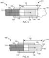
- FIGS. 2-7 are simplified cross-sectional views of exemplary laser fibers 102 in accordance with embodiments of the invention.
- FIG. 4 is a simplified cross-sectional view of a fiber tip of FIG. 4 taken generally along line 4-4.
- the system 100 comprises a laser generator 104 that generates laser energy 106 and a waveguide 108 optically coupling the laser generator 104 to the laser fiber 102.
- the laser fiber 102 either includes the waveguide 108 or is optically coupled to the waveguide 108.
- the laser energy 106 is discharged from a distal end of the laser fiber 102, i.e., the end of the laser fiber 102 that is adjacent to the treatment site of a patient, and can be used to perform a desired medical laser procedure, such as tissue ablation, or urinary or kidney stone fragmentation.
- the system 100 includes a probe 110 ( FIG. 1 ), in which at least a distal end of the laser fiber 102 is supported.
- the laser generator 104 comprises one or more conventional laser sources, such as laser resonators, that produce the laser energy 106 having desired properties.
- the system 100 produces the laser energy 106 in the form of a pulse train or continuous wave.
- the laser generator 102 includes Q-switched laser rods to produce the laser energy 106, such as, for example, a holmium doped yttrium aluminium garnet (Ho:YAG) laser rod, a thulium doped yttrium aluminium garnet (Tm:YAG) laser rod, or other conventional laser rod suitable for producing the desired laser energy 106.
- the laser energy 106 has a power of approximately l-50W, a pulse repetition frequency of l-2000Hz, and an energy level of lmJ-5J. Laser energy 106 having other parameters may also be used.
- the laser fiber 102 includes an optical fiber 112 and a fiber tip 114.
- the optical fiber 112 includes a terminating end surface 116 at a distal end 118.
- the fiber tip 114 includes a distal terminating end 120 that is spaced a predetermined distance 122 from the terminating end surface 116 of the optical fiber 112.
- the fiber tip 114 operates to protect the distal end 118 of the optical fiber.
- the fiber tip 114 can prevent or reduce damage to the distal end 118 of the optical fiber 112 that can occur during medical laser treatments due to contact between the distal end 118 of the optical fiber 112 and the targeted object for the laser energy 106, such as a calculus (i.e., kidney or bladder stone) 124 or tissue.
- the fiber tip 114 forms a sealed cavity 125 around the terminating end surface 116 of the optical fiber, as shown in FIG. 2 .
- the predetermined distance or spacing 122 is generally set to alleviate/control damage to the distal end 118 of the optical fiber 112, manipulate (focus or diffuse) a shock wave generated during laser lithotripsy, and improve ablation efficiency.
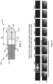
- FIG. 8 shows photos of laser lithotripsy operations using a Ho:YAG laser, and a Tm:YAG laser that show a bubble formation process and oscillations during the laser-stone interaction.
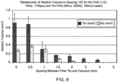
- FIG. 9 is a chart illustrating a relationship between an ablation volume and the spacing 122 between the terminating end surface 116 or fiber tip of the optical fiber 112 and the calculus 124 for a Ho:YAG laser (1.0 J, 10Hz, ⁇ 109 ⁇ s) and a Tm:YAG laser (40mJ, 250Hz, 190ns).
- the chart illustrates that the ablation efficiency for the Ho:YAG laser is higher when the spacing 122 is 0.5mm as compared to when the surface 116 of the optical fiber 112 is in contact with the calculus 124.
- the chart shows that the ablation efficiency of the Tm:YAG laser is similar over the spacing 122 of 0-0.5mm.
- the spacing 122 between the surface 116 of the optical fiber 112 and the targeted object (e.g., calculus 124) provided by the fiber tip 114 can allow for efficient ablation of the targeted object while protecting the optical fiber 122.
- the distance 122 is approximately 0.1-4 mm. In some embodiments, the distance 122 is 0.1mm-1mm.
- the fiber tip 114 is attached to the laser fiber 112, as shown in FIGS. 2 and 5-7 . In some embodiments, this involves attaching the fiber tip 114 to a core of the optical fiber 112, cladding of the optical fiber 112, and/or a jacket surrounding the cladding and core of the optical fiber 112, which are not shown in order to simplify the illustrations. In some embodiments, the fiber tip 114 is removably attached to the optical fiber 112. In some embodiments, the fiber tip 114 may be attached to the distal end 118 of the optical fiber 112 by hand, and may also be detached from the optical fiber 112 by hand.
- the optical fiber 112 may be supported within a fiber support 126, as shown in FIG. 3 .
- the fiber support 126 may be a tubular member through which the optical fiber 112 is inserted.
- the fiber tip 114 attaches directly to the fiber support 126 rather than the optical fiber 112, as shown in FIG. 3 .
- the fiber tip 114 is removably attachable to the fiber support 126.
- the attachment and removal of the fiber tip 114 from the fiber support 126 may be performed by hand.
- the fiber tip 114 includes a sleeve portion 128 that facilitates attachment of the fiber tip 114 to either the optical fiber 112 ( FIG. 2 ) or a fiber support 126 ( FIG. 3 ).
- at least a proximal end 130 of the sleeve portion 128 forms a socket that is configured to receive the distal end 118 of the optical fiber 112 ( FIG. 2 ) or a distal end 132 of the fiber support 126 ( FIG. 3 ).
- the sleeve portion 128 includes a shoulder 134 that is configured to engage the terminating end surface 116 of the optical fiber 112 ( FIG. 2 ) or an end surface 136 of the fiber support 126 ( FIG. 3 ) to position the terminating end 120 of the fiber tip 114 at the desired distance 122 from the terminating end surface 116 of the optical fiber 112.
- the fiber tip 114 includes a transmissive portion 140, through which the laser energy 106 discharged from the terminating end surface 116 of the optical fiber 112 is transmitted. In some embodiments, the laser energy 106 is discharged through the transmissive portion 140 along a longitudinal axis of the optical fiber 112.
- the fiber tip 114 includes a spacer portion 142 that defines the distal terminating end 120 of the fiber tip 114.
- the transmissive portion 140 includes the spacer portion 142, as shown in FIGS. 2 , 3 , 6 and 7 .
- the spacer portion 142 extends distally from the transmissive portion 140, as shown in FIG. 5 .
- the distal terminating end 120 of the spacer portion 142 is annular, as shown in FIG. 5 .
- the distally extending spacer portion 142 may comprise one or more projections.
- the sleeve portion 128 supports the transmissive portion 140 and the spacer portion 142. In some embodiments, the sleeve portion 128 surrounds the distal end 118 of the optical fiber 112. In some embodiments, the sleeve portion 128, the transmissive portion 140, and the spacer portion 142 are formed as a single component, as shown in FIG. 7 .
- components of the fiber tip 114 such as the transmissive portion 140, the spacer portion 142, and/or the sleeve portion 128, are formed of sapphire or hard glass.
- the transmissive portion 140 includes one or more lenses that assist in focusing or diffusing the laser energy 106 that is directed to the targeted object, such as a calculus 124.
- a lens 144 is located at the distal end of the transmissive portion 140, as shown in phantom in FIG. 2 .
- the transmissive portion 140 includes a lens 146 located at a proximal end of the transmissive portion 140, as shown in phantom in FIG. 2 .
- the distal terminating end 120 of the fiber tip 114 includes a convex surface 150, as shown in FIGS. 6 and 7 .
- the surface 150 may operate as the distal lens 144 ( FIG. 2 ).
- the convex surface 150 operates to diffuse the shock wave that occurs during laser lithotripsy to reduce retropulsion of the calculus or stone 124.
- Another embodiment of the invention is directed to a method of fragmenting a calculus using a laser fiber 102 formed in accordance with one or more embodiments of the present invention.
- the calculus 124 is engaged with the terminating end 120 of the fiber tip 114 to position the terminating end surface 116 of the optical fiber 112 at the predetermined distance 122 from the calculus, as shown in FIGS. 2 , 3 and 5 .
- Laser energy 106 is then transmitted through the optical fiber 112 and discharged through the terminating end surface 116.
- the calculus or stone 124 is exposed to the laser energy 106 while the calculus is at the predetermined distance 122 from the terminating end surface 116.
- the calculus is then fragmented responsive to the exposure of the calculus to the laser energy 106 and the shock wave generated thereby.
- fiber tips 114 can be detachably mounted to the laser fiber 102, the fiber tips 114 can be designed for specific procedures, types of calculi, etc. Accordingly, a single laser fiber can be used with different fiber tips 114 to perform multiple different types of procedures more efficiently and with better outcomes.
- the present subject-matter includes, inter-alia, the following aspects:
Landscapes
- Health & Medical Sciences (AREA)
- Physics & Mathematics (AREA)
- Surgery (AREA)
- Life Sciences & Earth Sciences (AREA)
- Optics & Photonics (AREA)
- Heart & Thoracic Surgery (AREA)
- Molecular Biology (AREA)
- Nuclear Medicine, Radiotherapy & Molecular Imaging (AREA)
- Engineering & Computer Science (AREA)
- Biomedical Technology (AREA)
- Electromagnetism (AREA)
- Medical Informatics (AREA)
- Otolaryngology (AREA)
- Animal Behavior & Ethology (AREA)
- General Health & Medical Sciences (AREA)
- Public Health (AREA)
- Veterinary Medicine (AREA)
- Laser Surgery Devices (AREA)
- Optical Couplings Of Light Guides (AREA)
- Radiation-Therapy Devices (AREA)
Abstract
Description
- Embodiments of the present invention generally relate to laser fibers for performing a medical laser treatment.
- Medical lasers have been used in various practice areas, such as, for example, urology, neurology, otorhinolaryngology, general anesthetic ophthalmology, dentistry, gastroenterology, cardiology, gynecology, and thoracic and orthopedic procedures. Generally, these procedures require precisely controlled delivery of laser energy as part of the treatment protocol.
- The treatment of kidney or bladder calculi or stones, Lithotripsy, is currently achieved through either ESWL (extracorporeal shock wave lithotripsy), surgery, or use of a laser (laser lithotripsy). In the laser application, a holmium doped yttrium aluminium garnet (Ho:YAG) laser rod, or a thulium doped yttrium aluminium garnet (Tm:YAG) laser rod, are used to produce laser energy having a wavelength of around 2000-2100 nm to break up stones of all types. The laser energy is typically in the form of a train of laser pulses, each having long pulse widths, such as approximately a few hundred microseconds. It is believed that a thermo-mechanical mechanism of action is in play for breaking up the stones, namely the laser energy superheats fluid in the vicinity of the stone, and creates a vaporization bubble. The vaporization bubble then expands as a shockwave and destabilizes the stone, causing it to fragment.
- There is a continuous demand for improvements to laser lithotripsy and other laser procedures, such as improved laser fibers for delivering laser energy to the targeted stone or tissue.
- Embodiments of the present invention generally relate to a laser fiber for use in performing a medical laser treatment, such as laser lithotripsy, surgical laser systems utilizing such laser fibers, and methods of performing laser lithotripsy procedures using the laser fibers. In some embodiments, the laser fiber includes an optical fiber and a fiber tip. The optical fiber includes a terminating end surface at a distal end. The fiber tip is positioned at the distal end of the optical fiber and includes a transmissive portion and a spacer portion. Laser energy discharged from the terminating end surface of the optical fiber is transmitted through the transmissive portion. The spacer portion defines a distal terminating end of the fiber tip that is spaced a predetermined distance from the terminating end surface of the optical fiber. The predetermined distance is set for shock wave generation for calculus destruction at the distal terminating end of the fiber tip.
- Embodiments of the surgical laser system include a laser generator and the optical fiber formed in accordance with one or more embodiments. The laser generator is configured to output laser energy that is optically coupled to a proximal end of the optical fiber. The laser energy is transmitted through the optical fiber and is discharged through the terminating end surface of the optical fiber and the fiber tip.
- In some embodiments of a method of fragmenting a calculus, the calculus is engaged with the terminating end of the fiber tip to position the terminating end surface of the optical fiber at the predetermined distance from the calculus. Laser energy is transmitted through the optical fiber. The laser energy is discharged through the terminating end surface of the optical fiber and the calculus is exposed to the laser energy while the calculus is maintained at the predetermined distance from the terminating end surface using the spacer portion. The calculus is fragmented in response to the exposure to the laser energy.
- This Summary is provided to introduce a selection of concepts in a simplified form that are further described below in the Detailed Description. This Summary is not intended to identify key features or essential features of the claimed subject matter, nor is it intended to be used as an aid in determining the scope of the claimed subject matter. The claimed subject matter is not limited to implementations that solve any or all disadvantages noted in the Background.
-
-
FIG. 1 is a schematic diagram of an exemplary surgical laser system in accordance with embodiments of the invention. -
FIGS. 2 and3 are simplified side cross-sectional views of a distal end of exemplary laser fibers in accordance with embodiments of the invention. -
FIG. 4 is a simplified cross-sectional view of a fiber tip ofFIG. 3 taken generally along line 4-4. -
FIGS. 5-7 are simplified side cross-sectional views of a distal end of exemplary laser fibers in accordance with embodiments of the invention. -
FIG. 8 shows photos of laser lithotripsy operations using exemplary lasers. -
FIG. 9 is a chart illustrating a relationship between an ablation volume and a spacing between a terminating end surface or fiber tip of an optical fiber and a calculus for two exemplary lasers. - Embodiments of the present invention generally relate to laser fibers for use in performing a medical laser treatment, such as laser lithotripsy, surgical laser systems utilizing such laser fibers, and methods of performing laser lithotripsy procedures using the laser fibers. Embodiments of the invention are described more fully hereinafter with reference to the accompanying drawings. The various embodiments of the invention may, however, be embodied in many different forms and should not be construed as limited to the embodiments set forth herein. Rather, these embodiments are provided so that this disclosure will be thorough and complete, and will fully convey the scope of the invention to those skilled in the art. Elements that are identified using the same or similar reference characters refer to the same or similar elements.
- The terminology used herein is for the purpose of describing particular embodiments only and is not intended to be limiting of the invention. As used herein, the singular forms "a", "an" and "the" are intended to include the plural forms as well, unless the context clearly indicates otherwise. It will be further understood that the terms "comprises" and/or "comprising," when used in this specification, specify the presence of stated features, integers, steps, operations, elements, and/or components, but do not preclude the presence or addition of one or more other features, integers, steps, operations, elements, components, and/or groups thereof.
- It will be understood that when an element is referred to as being "connected" or "coupled" to another element, it can be directly connected or coupled to the other element or intervening elements may be present. In contrast, if an element is referred to as being "directly connected" or "directly coupled" to another element, there are no intervening elements present.
- It will be understood that, although the terms first, second, etc. may be used herein to describe various elements, these elements should not be limited by these terms. These terms are only used to distinguish one element from another. Thus, a first element could be termed a second element without departing from the teachings of the present invention.
- Unless otherwise defined, all terms (including technical and scientific terms) used herein have the same meaning as commonly understood by one of ordinary skill in the art to which this invention belongs. It will be further understood that terms, such as those defined in commonly used dictionaries, should be interpreted as having a meaning that is consistent with their meaning in the context of the relevant art and will not be interpreted in an idealized or overly formal sense unless expressly so defined herein.
-
FIG. 1 is a schematic diagram of an exemplarysurgical laser system 100, which includes alaser fiber 102 in accordance with one or more embodiments of the invention.FIGS. 2-7 are simplified cross-sectional views ofexemplary laser fibers 102 in accordance with embodiments of the invention.FIG. 4 is a simplified cross-sectional view of a fiber tip ofFIG. 4 taken generally along line 4-4. - In some embodiments, the
system 100 comprises alaser generator 104 that generateslaser energy 106 and awaveguide 108 optically coupling thelaser generator 104 to thelaser fiber 102. Thelaser fiber 102 either includes thewaveguide 108 or is optically coupled to thewaveguide 108. Thelaser energy 106 is discharged from a distal end of thelaser fiber 102, i.e., the end of thelaser fiber 102 that is adjacent to the treatment site of a patient, and can be used to perform a desired medical laser procedure, such as tissue ablation, or urinary or kidney stone fragmentation. In some embodiments, thesystem 100 includes a probe 110 (FIG. 1 ), in which at least a distal end of thelaser fiber 102 is supported. - In some embodiments, the
laser generator 104 comprises one or more conventional laser sources, such as laser resonators, that produce thelaser energy 106 having desired properties. In some embodiments, thesystem 100 produces thelaser energy 106 in the form of a pulse train or continuous wave. In some embodiments, thelaser generator 102 includes Q-switched laser rods to produce thelaser energy 106, such as, for example, a holmium doped yttrium aluminium garnet (Ho:YAG) laser rod, a thulium doped yttrium aluminium garnet (Tm:YAG) laser rod, or other conventional laser rod suitable for producing the desiredlaser energy 106. In some embodiments thelaser energy 106 has a power of approximately l-50W, a pulse repetition frequency of l-2000Hz, and an energy level of lmJ-5J.Laser energy 106 having other parameters may also be used. - In some embodiments, the
laser fiber 102 includes anoptical fiber 112 and afiber tip 114. Theoptical fiber 112 includes a terminatingend surface 116 at adistal end 118. In some embodiments, thefiber tip 114 includes a distal terminatingend 120 that is spaced apredetermined distance 122 from the terminatingend surface 116 of theoptical fiber 112. In some embodiments, thefiber tip 114 operates to protect thedistal end 118 of the optical fiber. For instance, thefiber tip 114 can prevent or reduce damage to thedistal end 118 of theoptical fiber 112 that can occur during medical laser treatments due to contact between thedistal end 118 of theoptical fiber 112 and the targeted object for thelaser energy 106, such as a calculus (i.e., kidney or bladder stone) 124 or tissue. In some embodiments, thefiber tip 114 forms a sealedcavity 125 around the terminatingend surface 116 of the optical fiber, as shown inFIG. 2 . - In some embodiments, the predetermined distance or spacing 122 is generally set to alleviate/control damage to the
distal end 118 of theoptical fiber 112, manipulate (focus or diffuse) a shock wave generated during laser lithotripsy, and improve ablation efficiency.FIG. 8 shows photos of laser lithotripsy operations using a Ho:YAG laser, and a Tm:YAG laser that show a bubble formation process and oscillations during the laser-stone interaction.FIG. 9 is a chart illustrating a relationship between an ablation volume and thespacing 122 between the terminatingend surface 116 or fiber tip of theoptical fiber 112 and thecalculus 124 for a Ho:YAG laser (1.0 J, 10Hz, ~109µs) and a Tm:YAG laser (40mJ, 250Hz, 190ns). The chart illustrates that the ablation efficiency for the Ho:YAG laser is higher when thespacing 122 is 0.5mm as compared to when thesurface 116 of theoptical fiber 112 is in contact with thecalculus 124. Additionally, the chart shows that the ablation efficiency of the Tm:YAG laser is similar over the spacing 122 of 0-0.5mm. Thus, the spacing 122 between thesurface 116 of theoptical fiber 112 and the targeted object (e.g., calculus 124) provided by thefiber tip 114 can allow for efficient ablation of the targeted object while protecting theoptical fiber 122. In some embodiments, thedistance 122 is approximately 0.1-4 mm. In some embodiments, thedistance 122 is 0.1mm-1mm. - In some embodiments, the
fiber tip 114 is attached to thelaser fiber 112, as shown inFIGS. 2 and5-7 . In some embodiments, this involves attaching thefiber tip 114 to a core of theoptical fiber 112, cladding of theoptical fiber 112, and/or a jacket surrounding the cladding and core of theoptical fiber 112, which are not shown in order to simplify the illustrations. In some embodiments, thefiber tip 114 is removably attached to theoptical fiber 112. In some embodiments, thefiber tip 114 may be attached to thedistal end 118 of theoptical fiber 112 by hand, and may also be detached from theoptical fiber 112 by hand. - In some embodiments, the
optical fiber 112 may be supported within afiber support 126, as shown inFIG. 3 . Thefiber support 126 may be a tubular member through which theoptical fiber 112 is inserted. In some embodiments, thefiber tip 114 attaches directly to thefiber support 126 rather than theoptical fiber 112, as shown inFIG. 3 . In some embodiments, thefiber tip 114 is removably attachable to thefiber support 126. In some embodiments, the attachment and removal of thefiber tip 114 from thefiber support 126 may be performed by hand. - In some embodiments, the
fiber tip 114 includes asleeve portion 128 that facilitates attachment of thefiber tip 114 to either the optical fiber 112 (FIG. 2 ) or a fiber support 126 (FIG. 3 ). In some embodiments, at least aproximal end 130 of thesleeve portion 128 forms a socket that is configured to receive thedistal end 118 of the optical fiber 112 (FIG. 2 ) or adistal end 132 of the fiber support 126 (FIG. 3 ). In some embodiments, thesleeve portion 128 includes ashoulder 134 that is configured to engage the terminatingend surface 116 of the optical fiber 112 (FIG. 2 ) or anend surface 136 of the fiber support 126 (FIG. 3 ) to position the terminatingend 120 of thefiber tip 114 at the desireddistance 122 from the terminatingend surface 116 of theoptical fiber 112. - In some embodiments, the
fiber tip 114 includes atransmissive portion 140, through which thelaser energy 106 discharged from the terminatingend surface 116 of theoptical fiber 112 is transmitted. In some embodiments, thelaser energy 106 is discharged through thetransmissive portion 140 along a longitudinal axis of theoptical fiber 112. - In some embodiments, the
fiber tip 114 includes aspacer portion 142 that defines the distal terminatingend 120 of thefiber tip 114. In some embodiments, thetransmissive portion 140 includes thespacer portion 142, as shown inFIGS. 2 ,3 ,6 and7 . In some embodiments, thespacer portion 142 extends distally from thetransmissive portion 140, as shown inFIG. 5 . In some embodiments, the distal terminatingend 120 of thespacer portion 142 is annular, as shown inFIG. 5 . In other embodiments, the distally extendingspacer portion 142 may comprise one or more projections. - In some embodiments, the
sleeve portion 128 supports thetransmissive portion 140 and thespacer portion 142. In some embodiments, thesleeve portion 128 surrounds thedistal end 118 of theoptical fiber 112. In some embodiments, thesleeve portion 128, thetransmissive portion 140, and thespacer portion 142 are formed as a single component, as shown inFIG. 7 . - In some embodiments, components of the
fiber tip 114, such as thetransmissive portion 140, thespacer portion 142, and/or thesleeve portion 128, are formed of sapphire or hard glass. - In some embodiments, the
transmissive portion 140 includes one or more lenses that assist in focusing or diffusing thelaser energy 106 that is directed to the targeted object, such as acalculus 124. In some embodiments, alens 144 is located at the distal end of thetransmissive portion 140, as shown in phantom inFIG. 2 . In some embodiments, thetransmissive portion 140 includes alens 146 located at a proximal end of thetransmissive portion 140, as shown in phantom inFIG. 2 . - In some embodiments, the distal terminating
end 120 of thefiber tip 114 includes aconvex surface 150, as shown inFIGS. 6 and7 . Thesurface 150 may operate as the distal lens 144 (FIG. 2 ). In some embodiments, theconvex surface 150 operates to diffuse the shock wave that occurs during laser lithotripsy to reduce retropulsion of the calculus orstone 124. - Another embodiment of the invention is directed to a method of fragmenting a calculus using a
laser fiber 102 formed in accordance with one or more embodiments of the present invention. In the method, thecalculus 124 is engaged with the terminatingend 120 of thefiber tip 114 to position the terminatingend surface 116 of theoptical fiber 112 at thepredetermined distance 122 from the calculus, as shown inFIGS. 2 ,3 and5 .Laser energy 106 is then transmitted through theoptical fiber 112 and discharged through the terminatingend surface 116. The calculus orstone 124 is exposed to thelaser energy 106 while the calculus is at thepredetermined distance 122 from the terminatingend surface 116. The calculus is then fragmented responsive to the exposure of the calculus to thelaser energy 106 and the shock wave generated thereby. - Additionally, because
fiber tips 114 according to the embodiments of the present invention can be detachably mounted to thelaser fiber 102, thefiber tips 114 can be designed for specific procedures, types of calculi, etc. Accordingly, a single laser fiber can be used withdifferent fiber tips 114 to perform multiple different types of procedures more efficiently and with better outcomes. - Although the present invention has been described with reference to preferred embodiments, workers skilled in the art will recognize that changes may be made in form and detail without departing from the spirit and scope of the invention.
- The present subject-matter includes, inter-alia, the following aspects:
- 1. A laser fiber for performing laser lithotripsy comprising:
- an optical fiber having a distal end and a terminating end surface at the distal end; and
- a fiber tip at the distal end of the optical fiber, the fiber tip including a transmissive portion, through which laser energy discharged from the terminating end surface of the optical fiber is transmitted, and a spacer portion defining a distal terminating end of the fiber tip that is spaced a predetermined distance from the terminating end surface of the optical fiber;
- wherein the predetermined distance is set for shock wave generation for calculus destruction at the distal terminating end of the fiber tip.
- 2. The laser fiber according to
aspect 1, wherein the fiber tip is attached to the distal end of the optical fiber. - 3. The laser fiber according to
aspect 2, wherein the fiber tip is removably attached to the distal end of the optical fiber. - 4. The laser fiber according to
aspect 1, wherein the optical fiber is contained within a fiber support, and the fiber tip is attached to the fiber support. - 5. The laser fiber according to
aspect 4, wherein the fiber tip is removably attached to the fiber support. - 6. The laser fiber according to any of
aspects 1 to 5, wherein the transmissive portion includes the spacer portion. - 7. The laser fiber according to any of
aspects 1 to 5, wherein the spacer portion extends distally from the transmissive portion. - 8. The laser fiber according to any of
aspects 1 to 7, wherein the fiber tip comprises a sleeve portion having a proximal end that surrounds the distal end of the optical fiber and supports the transmissive portion and the spacer portion. - 9. The laser fiber according to any of
aspects 1 to 8, wherein the transmissive portion comprises a lens that focuses laser energy discharged from the terminating end surface of the optical fiber. - 10. The laser fiber according to aspect 9, wherein the lens is positioned at a proximal end of the transmissive portion.
- 11. The laser fiber according to aspect 9, wherein the lens is positioned at a distal end of the transmissive portion.
- 12. The laser fiber according to any of
aspects 1 to 11, wherein the distal terminating end of the fiber tip has a convex surface. - 13. The laser fiber according to any of the
aspects 1 to 12, wherein the fiber tip forms a sealed cavity around the terminating end surface of the optical fiber. - 14. A surgical laser system comprising a laser fiber according to any of
aspects 1 to 13 and a laser generator configured to output laser energy that is optically coupled to a proximal end of the optical fiber, wherein the laser energy is transmitted through the optical fiber and is discharged through the terminating end surface of the optical fiber and the fiber tip. - 15. A method of fragmenting a calculus using a laser fiber according to any of
aspects 1 to 14 comprising:- engaging the calculus with the terminating end of the fiber tip to position the terminating end surface of the optical fiber at the predetermined distance from the calculus;
- transmitting laser energy through the optical fiber;
- discharging the laser energy through the terminating end surface of the optical fiber;
- exposing the calculus to the laser energy while the calculus is maintained at the predetermined distance from the terminating end surface using the spacer portion; and
- fragmenting the calculus in response to exposing the calculus to the laser energy.
Claims (15)
- A laser fiber (102), comprising:an optical fiber (112) including:a longitudinal axis,a proximal end configured to be optically coupled to a laser energy (106),a distal end (118), anda terminating end surface (116) at the distal end (118) configured to discharge the laser energy (106); anda fiber tip (114) positioned at the distal end (118) of the optical fiber (112), the fiber tip (114) including:a transmissive portion (140) that is configured to receive the laser energy discharged from the terminating end surface (116) of the optical fiber (112) and to transmit the laser energy (106), the transmissive portion (140) including one or more lenses (144, 146) located at a proximal end and/or a distal end of the transmissive portion (140),a spacer portion (142) that defines a distal terminating end (120) of the fiber tip (114), anda sleeve portion (128) including a shoulder (134) that is configured to engage the terminating end surface (116) of the optical fiber (112) to position the distal terminating end (120) of the fiber tip (114) at a predetermined distance (122) from the terminating end surface (116) of the optical fiber (112).
- The laser fiber (102) of claim 1, wherein the transmissive portion (140), the spacer portion (142), and the sleeve portion (128) are each formed of sapphire or hard glass.
- The laser fiber (102) of claim 1 or 2, wherein the fiber tip (114) forms a sealed cavity (125) around the terminating end surface (116) of the optical fiber.
- The laser fiber (102) of any one of claims 1 to 3, wherein the fiber tip (114) is detachably connected to the optical fiber (112).
- The laser fiber (102) of any one of claims 1 to 4, wherein the predetermined distance (122) is in a range of from 0.10 mm to 4 mm.
- The laser fiber (102) of any one of claims 1 to 5, wherein the proximal end of the optical fiber (122) is configured to be optically coupled to a laser generator (104) and receive the laser energy (106) from the laser generator (104).
- The laser fiber (102) of any one of claims 1 to 6, wherein the spacer portion (142) extends distally from the transmissive portion (140).
- The laser fiber (102) of claim 7, wherein the distal terminating end (120) of the spacer portion (142) is annular.
- The laser fiber (102) of any one of claims 1 to 8, wherein the sleeve portion (128), the transmissive portion (140), and the spacer portion (142) are formed as a single component.
- The laser fiber (102) of any one of claims 1 to 9, wherein the transmissive portion (140) extends distally from the sleeve portion (128).
- The laser fiber (102) of any one of claims 1 to 10, wherein the one or more lenses (144, 146) comprise a first lens (144) located at the proximal end of the transmissive portion (140), the first lens (144) configured to focus laser energy discharged from the terminating end surface (116) of the optical fiber (112).
- The laser fiber (102) of claim 11, wherein the one or more lenses (144, 146) comprise a second lens (146) located at the distal end of the transmissive portion (140), the second lens (146) configured to focus laser energy discharged from the terminating end surface (116) of the optical fiber (112).
- The laser fiber (102) of any one of claims 1 to 12, wherein the distal terminating end (120) of the fiber tip (114) has a convex surface.
- The laser fiber (102) of any one of claims 1 to 13, wherein the predetermined distance (122) is set for shock wave generation for calculus destruction at the distal terminating end (120) of the fiber tip (114).
- A surgical laser system comprising a laser fiber (102) according to any of claims 1 to 14 and a laser generator (104) configured to output laser energy that is optically coupled to the proximal end of the optical fiber (112), wherein the laser energy is transmitted through the optical fiber (112) and is discharged through the terminating end surface (116) of the optical fiber (112) and the fiber tip (114).
Applications Claiming Priority (4)
| Application Number | Priority Date | Filing Date | Title |
|---|---|---|---|
| US201462054582P | 2014-09-24 | 2014-09-24 | |
| PCT/US2015/051687 WO2016049160A1 (en) | 2014-09-24 | 2015-09-23 | Laser lithotripsy system |
| EP20157020.7A EP3673853B1 (en) | 2014-09-24 | 2015-09-23 | Laser lithotripsy system |
| EP15775348.4A EP3197381B1 (en) | 2014-09-24 | 2015-09-23 | Laser lithotripsy system |
Related Parent Applications (2)
| Application Number | Title | Priority Date | Filing Date |
|---|---|---|---|
| EP20157020.7A Division EP3673853B1 (en) | 2014-09-24 | 2015-09-23 | Laser lithotripsy system |
| EP15775348.4A Division EP3197381B1 (en) | 2014-09-24 | 2015-09-23 | Laser lithotripsy system |
Publications (2)
| Publication Number | Publication Date |
|---|---|
| EP4413938A2 true EP4413938A2 (en) | 2024-08-14 |
| EP4413938A3 EP4413938A3 (en) | 2024-09-18 |
Family
ID=54252430
Family Applications (3)
| Application Number | Title | Priority Date | Filing Date |
|---|---|---|---|
| EP15775348.4A Active EP3197381B1 (en) | 2014-09-24 | 2015-09-23 | Laser lithotripsy system |
| EP20157020.7A Active EP3673853B1 (en) | 2014-09-24 | 2015-09-23 | Laser lithotripsy system |
| EP24179752.1A Pending EP4413938A3 (en) | 2014-09-24 | 2015-09-23 | Laser lithotripsy system |
Family Applications Before (2)
| Application Number | Title | Priority Date | Filing Date |
|---|---|---|---|
| EP15775348.4A Active EP3197381B1 (en) | 2014-09-24 | 2015-09-23 | Laser lithotripsy system |
| EP20157020.7A Active EP3673853B1 (en) | 2014-09-24 | 2015-09-23 | Laser lithotripsy system |
Country Status (4)
| Country | Link |
|---|---|
| US (1) | US12303193B2 (en) |
| EP (3) | EP3197381B1 (en) |
| CN (1) | CN106604690A (en) |
| WO (1) | WO2016049160A1 (en) |
Families Citing this family (6)
| Publication number | Priority date | Publication date | Assignee | Title |
|---|---|---|---|---|
| JP6672479B2 (en) | 2016-05-18 | 2020-03-25 | ジャイラス・エーシーエムアイ・インコーポレーテッド | Apparatus and method for laser lithotripsy |
| US10405923B2 (en) | 2016-08-12 | 2019-09-10 | Boston Scientific Scimed, Inc. | Systems, devices, and related methods for laser lithotripsy |
| US12446961B2 (en) | 2020-02-10 | 2025-10-21 | Bolt Medical, Inc. | System and method for pressure monitoring within a catheter system |
| US12611253B2 (en) | 2020-03-18 | 2026-04-28 | Boston Scientific Scimed, Inc. | Optical analyzer assembly and method for intravascular lithotripsy device |
| US20210353359A1 (en) | 2020-05-12 | 2021-11-18 | Bolt Medical, Inc. | Active alignment system and method for optimizing optical coupling of multiplexer for laser-driven intravascular lithotripsy device |
| US20240130788A1 (en) * | 2022-02-04 | 2024-04-25 | Gyrus Acmi, Inc. D/B/A Olympus Surgical Technologies America | Medical devices with protected light conductors |
Family Cites Families (104)
| Publication number | Priority date | Publication date | Assignee | Title |
|---|---|---|---|---|
| US3467098A (en) | 1967-03-24 | 1969-09-16 | Becton Dickinson Co | Flexible conduit for laser surgery |
| US4204743A (en) * | 1976-06-21 | 1980-05-27 | U.S. Philips Corporation | Connector for coupling optical fibers to an emitter or receiver of luminous energy |
| US4273109A (en) | 1976-07-06 | 1981-06-16 | Cavitron Corporation | Fiber optic light delivery apparatus and medical instrument utilizing same |
| DE3506249A1 (en) * | 1985-02-22 | 1986-08-28 | Messerschmitt-Bölkow-Blohm GmbH, 8012 Ottobrunn | METHOD AND DEVICE FOR SMASHING A SOLID BODY |
| US5167686A (en) * | 1985-03-06 | 1992-12-01 | C. R. Bard, Inc. | Catheter system for controlled removal by radiant energy of biological obstructions |
| US4817601A (en) * | 1985-03-06 | 1989-04-04 | C. R. Bard, Inc. | Catheter system for controlled removal by radiant energy of biological obstructions |
| US4718417A (en) | 1985-03-22 | 1988-01-12 | Massachusetts Institute Of Technology | Visible fluorescence spectral diagnostic for laser angiosurgery |
| US5693043A (en) * | 1985-03-22 | 1997-12-02 | Massachusetts Institute Of Technology | Catheter for laser angiosurgery |
| US4850351A (en) * | 1985-05-22 | 1989-07-25 | C. R. Bard, Inc. | Wire guided laser catheter |
| EP0214712B1 (en) * | 1985-07-31 | 1992-09-02 | C.R. Bard, Inc. | Infrared laser catheter apparatus |
| US4917084A (en) * | 1985-07-31 | 1990-04-17 | C. R. Bard, Inc. | Infrared laser catheter system |
| US4707073A (en) | 1985-09-04 | 1987-11-17 | Raytheon Company | Fiber optic beam delivery system for high-power laser |
| US4732449A (en) | 1985-10-25 | 1988-03-22 | G & H Technology | Beam splitter |
| US4695697A (en) | 1985-12-13 | 1987-09-22 | Gv Medical, Inc. | Fiber tip monitoring and protection assembly |
| US4865029A (en) | 1986-04-24 | 1989-09-12 | Eye Research Institute Of Retina Foundation | Endophotocoagulation probe |
| US4838246A (en) | 1986-08-13 | 1989-06-13 | Messerschmitt-Bolkow-Blohm Gmbh | Application part for an endoscope |
| DE3727003A1 (en) * | 1986-08-13 | 1988-02-25 | Messerschmitt Boelkow Blohm | Application part for a rigid or flexible endoscope |
| EP0268019A1 (en) | 1986-11-13 | 1988-05-25 | Messerschmitt-Bölkow-Blohm Gesellschaft mit beschränkter Haftung | Apparatus for disintegrating a fluid-suspended solid body |
| US4867136A (en) | 1987-04-23 | 1989-09-19 | Olympus Optical Co., Ltd. | Endoscope apparatus |
| US5112328A (en) | 1988-01-25 | 1992-05-12 | Refractive Laser Research & Development Program, Ltd. | Method and apparatus for laser surgery |
| DE3836337A1 (en) * | 1988-10-25 | 1990-04-26 | Meessen Stephan Dr B | Method and device for recording intracorporally generated, laser-induced shock waves |
| DE3842916C1 (en) | 1988-12-21 | 1990-02-01 | Messerschmitt-Boelkow-Blohm Gmbh, 8012 Ottobrunn, De | |
| US5425735A (en) | 1989-02-22 | 1995-06-20 | Psi Medical Products, Inc. | Shielded tip catheter for lithotripsy |
| US5019040A (en) | 1989-08-31 | 1991-05-28 | Koshin Sangyo Kabushiki Kaisha | Catheter |
| DE3933613C2 (en) * | 1989-10-07 | 1998-10-08 | Laser & Med Tech Gmbh | Device for generating laser-induced shock waves |
| CA2067776C (en) | 1989-10-25 | 2001-09-04 | Jack Murray Dodick | Surgical instrument with input power transducer |
| US5257989A (en) | 1990-02-07 | 1993-11-02 | Coherent, Inc. | Contact laser delivery probe |
| US5304171A (en) | 1990-10-18 | 1994-04-19 | Gregory Kenton W | Catheter devices and methods for delivering |
| US5093877A (en) | 1990-10-30 | 1992-03-03 | Advanced Cardiovascular Systems | Optical fiber lasing apparatus lens |
| US6110167A (en) * | 1990-10-31 | 2000-08-29 | Premier Laser Systems, Inc. | Contact tip for laser surgery |
| US5269777A (en) * | 1990-11-01 | 1993-12-14 | Pdt Systems, Inc. | Diffusion tip for optical fibers |
| US5224942A (en) | 1992-01-27 | 1993-07-06 | Alcon Surgical, Inc. | Surgical method and apparatus utilizing laser energy for removing body tissue |
| JPH08501224A (en) * | 1992-04-10 | 1996-02-13 | プレミア・ラザー・システムズ・インコーポレイテツド | Device and method for eye surgery |
| US5291570A (en) | 1992-09-09 | 1994-03-01 | Hobart Laser Products, Inc. | High power laser - optical fiber connection system |
| US5342355A (en) * | 1992-10-19 | 1994-08-30 | Laser Centers Of America | Energy delivering cap element for end of optic fiber conveying laser energy |
| US5553629A (en) | 1993-03-11 | 1996-09-10 | The United States Of America As Represented By The Secretary Of The Air Force | Portable medical laser pack system |
| FR2709763B1 (en) | 1993-09-08 | 1995-10-13 | Commissariat Energie Atomique | Device for processing a material, with miniaturized photo-ion head. |
| US5526455A (en) | 1993-09-17 | 1996-06-11 | Sumitomo Electric Industries, Ltd. | Connector including opposing lens surfaces, side surfaces, and contact surfaces for coupling optical devices |
| JP3167844B2 (en) | 1993-10-08 | 2001-05-21 | テルモ株式会社 | Solid-state laser device |
| US5496309A (en) * | 1994-05-06 | 1996-03-05 | Trimedyne, Inc. | Catheter device utilizing a laser beam laterally directed by a high index prism in a liquid medium |
| US5599341A (en) | 1994-06-15 | 1997-02-04 | Keravision, Inc. | Laser surgical procedure and device for treatment of the cornea |
| US5562657A (en) * | 1994-09-19 | 1996-10-08 | Griffin; Stephen E. | Side fire laser catheter method and apparatus |
| US5738676A (en) | 1995-01-03 | 1998-04-14 | Hammer; Daniel X. | Laser surgical probe for use in intraocular surgery |
| CA2146737C (en) | 1995-04-10 | 2001-08-14 | Yihao Cheng | Integrated optical isolator |
| US5921981A (en) | 1995-11-09 | 1999-07-13 | Alcon Laboratories, Inc. | Multi-spot laser surgery |
| US5680237A (en) | 1995-11-16 | 1997-10-21 | Jds Fitel Inc. | Graded index lens system and method for coupling light |
| US5815623A (en) * | 1996-01-18 | 1998-09-29 | Methode Electronics, Inc. | Optical package with alignment means and method of assembling an optical package |
| US5944687A (en) * | 1996-04-24 | 1999-08-31 | The Regents Of The University Of California | Opto-acoustic transducer for medical applications |
| US5840075A (en) | 1996-08-23 | 1998-11-24 | Eclipse Surgical Technologies, Inc. | Dual laser device for transmyocardial revascularization procedures |
| DE69825447T2 (en) | 1997-05-15 | 2005-09-15 | Palomar Medical Technologies, Inc., Burlington | DEVICE FOR DERMATOLOGICAL TREATMENT |
| US6393179B1 (en) | 1997-07-18 | 2002-05-21 | Jds Fitel Inc. | Optical coupling system |
| US6157485A (en) | 1997-07-18 | 2000-12-05 | Cheng; Yihao | Lens arrangement for enhancing the coupling of light shifted by an optical element |
| US6142630A (en) | 1998-05-08 | 2000-11-07 | Koester; Charles J. | Variable focus lens system such as for examination or treatment of transparent or semi-transparent materials such as ocular tissue |
| US6175673B1 (en) | 1998-10-29 | 2001-01-16 | Jds Fitel Inc. | Lensed sleeve |
| US6203537B1 (en) * | 1999-02-04 | 2001-03-20 | Sorin Adrian | Laser-driven acoustic ablation catheter |
| US6484052B1 (en) | 1999-03-30 | 2002-11-19 | The Regents Of The University Of California | Optically generated ultrasound for enhanced drug delivery |
| CN100426050C (en) | 1999-07-26 | 2008-10-15 | 拉博斯费尔株式会社 | Volume lens, light emitting body, lighting device, and optical information system |
| US6219481B1 (en) | 1999-08-05 | 2001-04-17 | Jds Fitel Inc. | Optical filter |
| US6556747B2 (en) | 2001-02-09 | 2003-04-29 | Lightmatrix Technologies, Inc. | Chemical mill method and structure formed thereby |
| US6748137B2 (en) | 2001-04-30 | 2004-06-08 | Jds Uniphase Corporation | Lensed optical fiber |
| US20020186742A1 (en) | 2001-05-03 | 2002-12-12 | Flint Graham W. | Single mode autocoupled resonator for telecommunications |
| GB0111363D0 (en) | 2001-05-09 | 2001-07-04 | Point Source Ltd | Optical component |
| US6692431B2 (en) | 2001-09-07 | 2004-02-17 | Smith & Nephew, Inc. | Endoscopic system with a solid-state light source |
| US8038602B2 (en) | 2001-10-19 | 2011-10-18 | Visionscope Llc | Portable imaging system employing a miniature endoscope |
| US10595710B2 (en) | 2001-10-19 | 2020-03-24 | Visionscope Technologies Llc | Portable imaging system employing a miniature endoscope |
| US6863651B2 (en) | 2001-10-19 | 2005-03-08 | Visionscope, Llc | Miniature endoscope with imaging fiber system |
| US20040004055A1 (en) | 2002-01-18 | 2004-01-08 | Barros Emanuel F. | Method and apparatus for the controlled formation of cavitation bubbles |
| US6960307B2 (en) | 2002-01-18 | 2005-11-01 | Leclair Mark L | Method and apparatus for the controlled formation of cavitation bubbles |
| US20060200113A1 (en) | 2002-03-07 | 2006-09-07 | David Haffner | Liquid jet for glaucoma treatment |
| WO2008124790A2 (en) * | 2002-07-10 | 2008-10-16 | Angiodynamics, Inc. | Device and method for endovascular treatment for causing closure of a blood vessel |
| US6945674B2 (en) | 2002-07-16 | 2005-09-20 | Ccs, Inc. | Light irradiating unit |
| US20040052475A1 (en) * | 2002-09-18 | 2004-03-18 | E-Pin Optical Industry Co., Ltd. | Fiber collimator and method of manufacturing the same |
| US20040097791A1 (en) | 2002-11-13 | 2004-05-20 | Olympus Corporation | Endoscope |
| JP2005013708A (en) | 2003-05-30 | 2005-01-20 | Olympus Corp | Endoscope and method for assembling it |
| DE10342016A1 (en) * | 2003-09-11 | 2005-04-14 | Siemens Ag | Lithotripsy device |
| US20050113814A1 (en) * | 2003-11-24 | 2005-05-26 | Loeb Marvin P. | Apparatus and method for limiting the re-use of fiber optic, laser energy delivery devices |
| JP4722912B2 (en) | 2005-03-08 | 2011-07-13 | オリンパスメディカルシステムズ株式会社 | Endoscope, endoscope manufacturing method |
| US20070027443A1 (en) * | 2005-06-29 | 2007-02-01 | Ondine International, Ltd. | Hand piece for the delivery of light and system employing the hand piece |
| US20080108867A1 (en) | 2005-12-22 | 2008-05-08 | Gan Zhou | Devices and Methods for Ultrasonic Imaging and Ablation |
| JP2007193006A (en) * | 2006-01-18 | 2007-08-02 | Nippon Electric Glass Co Ltd | Optical component for optical communication |
| US20070195548A1 (en) | 2006-02-17 | 2007-08-23 | Bwt Property, Inc. | Light Emitting Panel for Medical Applications |
| EP1903361B1 (en) | 2006-09-22 | 2020-04-01 | Nippon Electric Glass Co., Ltd. | Optical component and light emitting device using the same |
| JP5366575B2 (en) | 2008-05-08 | 2013-12-11 | Hoya株式会社 | Multiple types of endoscope |
| US9289262B2 (en) | 2008-05-19 | 2016-03-22 | Boston Scientific Scimed, Inc. | Dielectric coatings for laser fiber and related methods |
| EP2376960A1 (en) * | 2008-12-22 | 2011-10-19 | AMS Research Corporation | Sapphire-based delivery tip for optic fiber |
| US8679103B2 (en) * | 2008-12-22 | 2014-03-25 | Valam Corporation | Two step mammalian biofilm treatment processes and systems |
| US8109676B2 (en) | 2009-06-12 | 2012-02-07 | Applied Micro Circuits Corporation | Fiber optic cable with high interface mismatch tolerance |
| JP4866961B2 (en) | 2010-04-16 | 2012-02-01 | 三菱鉛筆株式会社 | Optical collimator, optical connector using the same, and optical collimator holding member |
| US9429717B2 (en) | 2010-06-29 | 2016-08-30 | Fujikura Ltd. | Ferrule and ferrule with optical fiber |
| JP5435739B2 (en) | 2010-10-19 | 2014-03-05 | 国立大学法人東北大学 | Optical fiber and underwater shock wave generator using the same |
| CN102370520B (en) * | 2011-11-03 | 2013-09-18 | 温海涛 | Laser gravel fixing forceps |
| US8571364B2 (en) | 2011-11-09 | 2013-10-29 | Alcon Research, Ltd. | Multi-spot laser probe with faceted optical element |
| US8861900B2 (en) | 2012-02-23 | 2014-10-14 | Corning Incorporated | Probe optical assemblies and probes for optical coherence tomography |
| US8967885B2 (en) | 2012-02-23 | 2015-03-03 | Corning Incorporated | Stub lens assemblies for use in optical coherence tomography systems |
| US9588302B2 (en) | 2012-06-01 | 2017-03-07 | Te Connectivity Corporation | Expanded-beam connector with molded lens |
| US8711336B1 (en) | 2012-11-01 | 2014-04-29 | National Security Technologies, Llc | Multipoint photonic doppler velocimetry using optical lens elements |
| US20160184022A1 (en) | 2013-03-13 | 2016-06-30 | The Spectranetics Corporation | Laser-induced pressure wave emitting catheter sheath |
| CN105338883A (en) | 2013-03-15 | 2016-02-17 | 奥利弗医疗公司 | Mechanical image rotation for rigidly coupled image sensor and endoscope |
| CN105611865B (en) | 2013-12-18 | 2018-06-19 | 奥林巴斯株式会社 | Endoscopic system |
| WO2015112770A1 (en) | 2014-01-22 | 2015-07-30 | The Regents Of The University Of Colorado, A Body Corporate | Optical imaging devices and variable-focus lens elements, and methods for using them |
| US9645325B2 (en) | 2015-05-01 | 2017-05-09 | Corning Optical Communications LLC | Expanded-beam ferrule with high coupling efficiency for optical interface devices |
| US9838576B2 (en) | 2015-08-31 | 2017-12-05 | Panasonic Corporation | Endoscope |
| US9829698B2 (en) | 2015-08-31 | 2017-11-28 | Panasonic Corporation | Endoscope |
| US10905322B2 (en) | 2019-03-26 | 2021-02-02 | John L. Bala | Bala Laparoscope System |
-
2015
- 2015-09-23 WO PCT/US2015/051687 patent/WO2016049160A1/en not_active Ceased
- 2015-09-23 EP EP15775348.4A patent/EP3197381B1/en active Active
- 2015-09-23 EP EP20157020.7A patent/EP3673853B1/en active Active
- 2015-09-23 EP EP24179752.1A patent/EP4413938A3/en active Pending
- 2015-09-23 CN CN201580047794.XA patent/CN106604690A/en active Pending
-
2022
- 2022-08-03 US US17/817,254 patent/US12303193B2/en active Active
Also Published As
| Publication number | Publication date |
|---|---|
| US20220370130A1 (en) | 2022-11-24 |
| CN106604690A (en) | 2017-04-26 |
| EP4413938A3 (en) | 2024-09-18 |
| EP3673853A1 (en) | 2020-07-01 |
| US12303193B2 (en) | 2025-05-20 |
| EP3673853B1 (en) | 2024-06-12 |
| EP3197381A1 (en) | 2017-08-02 |
| EP3197381B1 (en) | 2020-03-25 |
| WO2016049160A1 (en) | 2016-03-31 |
Similar Documents
| Publication | Publication Date | Title |
|---|---|---|
| US11439465B2 (en) | Surgical laser systems and laser lithotripsy techniques | |
| US12303193B2 (en) | Surgical laser systems and laser lithotripsy techniques | |
| US5224942A (en) | Surgical method and apparatus utilizing laser energy for removing body tissue | |
| US12396891B2 (en) | Laser apparatus for treatment of a cataractous lens | |
| EP2753262B1 (en) | Split surgical laser fiber | |
| US6544254B1 (en) | Combination ultrasound and laser method and apparatus for removing cataract lenses | |
| JP3113274B2 (en) | Surgical device with input power converter | |
| US5059200A (en) | Laser lithotripsy | |
| Capaccio et al. | Salivary lithotripsy in the era of sialendoscopy | |
| Grocela et al. | Intracorporeal lithotripsy: instrumentation and development | |
| CA2117765A1 (en) | Apparatus and method for performing eye surgery | |
| JP5892555B2 (en) | Laser assembly with shock absorber | |
| US20140336626A1 (en) | Medical assembly using short pulse fiber laser | |
| US7690382B2 (en) | System and method for salivary stones removal and joint arthroscopy | |
| EP0335714A2 (en) | Means for tissue removal using laser technology | |
| WO1995024867A1 (en) | Laser energy concentration in laser powered surgical instrument | |
| US20020128637A1 (en) | Laser scalpel | |
| US20140226933A1 (en) | Side fire laser assembly | |
| US20200054397A1 (en) | Method of reducing stone fragments to dust during laser lithotripsy | |
| US20050113814A1 (en) | Apparatus and method for limiting the re-use of fiber optic, laser energy delivery devices | |
| Chaney et al. | Hybrid germanium/silica optical fibers for endoscopic delivery of erbium: YAG laser radiation | |
| CN203447359U (en) | Laser operation device used in human organ | |
| CN223787667U (en) | A coaxial basket negative pressure conduit | |
| Chaney et al. | Assembly and testing of germanium/silica optical fibers for flexible endoscopic delivery of erbium: YAG laser radiation | |
| Miller et al. | Tissue ablation via optical fibre delivery of UV laser radiation |
Legal Events
| Date | Code | Title | Description |
|---|---|---|---|
| PUAI | Public reference made under article 153(3) epc to a published international application that has entered the european phase |
Free format text: ORIGINAL CODE: 0009012 |
|
| STAA | Information on the status of an ep patent application or granted ep patent |
Free format text: STATUS: REQUEST FOR EXAMINATION WAS MADE |
|
| 17P | Request for examination filed |
Effective date: 20240703 |
|
| AC | Divisional application: reference to earlier application |
Ref document number: 3197381 Country of ref document: EP Kind code of ref document: P Ref document number: 3673853 Country of ref document: EP Kind code of ref document: P |
|
| AK | Designated contracting states |
Kind code of ref document: A2 Designated state(s): AL AT BE BG CH CY CZ DE DK EE ES FI FR GB GR HR HU IE IS IT LI LT LU LV MC MK MT NL NO PL PT RO RS SE SI SK SM TR |
|
| PUAL | Search report despatched |
Free format text: ORIGINAL CODE: 0009013 |
|
| AK | Designated contracting states |
Kind code of ref document: A3 Designated state(s): AL AT BE BG CH CY CZ DE DK EE ES FI FR GB GR HR HU IE IS IT LI LT LU LV MC MK MT NL NO PL PT RO RS SE SI SK SM TR |
|
| RIC1 | Information provided on ipc code assigned before grant |
Ipc: A61B 18/22 20060101ALI20240809BHEP Ipc: A61B 18/26 20060101AFI20240809BHEP |
|
| RIN1 | Information on inventor provided before grant (corrected) |
Inventor name: RAJABHANDHARAKS, DANOP Inventor name: XUAN, RONGWEI JASON Inventor name: ZHANG, JIAN JAMES |
|
| GRAP | Despatch of communication of intention to grant a patent |
Free format text: ORIGINAL CODE: EPIDOSNIGR1 |
|
| STAA | Information on the status of an ep patent application or granted ep patent |
Free format text: STATUS: GRANT OF PATENT IS INTENDED |
|
| INTG | Intention to grant announced |
Effective date: 20260325 |