EP4413933A2 - Suture linkage for inhibiting premature embolic implant deployment - Google Patents
Suture linkage for inhibiting premature embolic implant deployment Download PDFInfo
- Publication number
- EP4413933A2 EP4413933A2 EP24186079.0A EP24186079A EP4413933A2 EP 4413933 A2 EP4413933 A2 EP 4413933A2 EP 24186079 A EP24186079 A EP 24186079A EP 4413933 A2 EP4413933 A2 EP 4413933A2
- Authority
- EP
- European Patent Office
- Prior art keywords
- pull wire
- distal
- proximal
- hooked end
- delivery system
- Prior art date
- Legal status (The legal status is an assumption and is not a legal conclusion. Google has not performed a legal analysis and makes no representation as to the accuracy of the status listed.)
- Pending
Links
Images



Classifications
-
- A—HUMAN NECESSITIES
- A61—MEDICAL OR VETERINARY SCIENCE; HYGIENE
- A61B—DIAGNOSIS; SURGERY; IDENTIFICATION
- A61B17/00—Surgical instruments, devices or methods
- A61B17/04—Surgical instruments, devices or methods for suturing wounds; Holders or packages for needles or suture materials
- A61B17/0485—Devices or means, e.g. loops, for capturing the suture thread and threading it through an opening of a suturing instrument or needle eyelet
-
- A—HUMAN NECESSITIES
- A61—MEDICAL OR VETERINARY SCIENCE; HYGIENE
- A61B—DIAGNOSIS; SURGERY; IDENTIFICATION
- A61B17/00—Surgical instruments, devices or methods
- A61B17/12—Surgical instruments, devices or methods for ligaturing or otherwise compressing tubular parts of the body, e.g. blood vessels or umbilical cord
- A61B17/12022—Occluding by internal devices, e.g. balloons or releasable wires
-
- A—HUMAN NECESSITIES
- A61—MEDICAL OR VETERINARY SCIENCE; HYGIENE
- A61B—DIAGNOSIS; SURGERY; IDENTIFICATION
- A61B17/00—Surgical instruments, devices or methods
- A61B17/12—Surgical instruments, devices or methods for ligaturing or otherwise compressing tubular parts of the body, e.g. blood vessels or umbilical cord
- A61B17/12022—Occluding by internal devices, e.g. balloons or releasable wires
- A61B17/12027—Type of occlusion
- A61B17/12031—Type of occlusion complete occlusion
-
- A—HUMAN NECESSITIES
- A61—MEDICAL OR VETERINARY SCIENCE; HYGIENE
- A61B—DIAGNOSIS; SURGERY; IDENTIFICATION
- A61B17/00—Surgical instruments, devices or methods
- A61B17/12—Surgical instruments, devices or methods for ligaturing or otherwise compressing tubular parts of the body, e.g. blood vessels or umbilical cord
- A61B17/12022—Occluding by internal devices, e.g. balloons or releasable wires
- A61B17/12099—Occluding by internal devices, e.g. balloons or releasable wires characterised by the location of the occluder
- A61B17/12109—Occluding by internal devices, e.g. balloons or releasable wires characterised by the location of the occluder in a blood vessel
- A61B17/12113—Occluding by internal devices, e.g. balloons or releasable wires characterised by the location of the occluder in a blood vessel within an aneurysm
-
- A—HUMAN NECESSITIES
- A61—MEDICAL OR VETERINARY SCIENCE; HYGIENE
- A61B—DIAGNOSIS; SURGERY; IDENTIFICATION
- A61B17/00—Surgical instruments, devices or methods
- A61B17/12—Surgical instruments, devices or methods for ligaturing or otherwise compressing tubular parts of the body, e.g. blood vessels or umbilical cord
- A61B17/12022—Occluding by internal devices, e.g. balloons or releasable wires
- A61B17/12131—Occluding by internal devices, e.g. balloons or releasable wires characterised by the type of occluding device
- A61B17/1214—Coils or wires
-
- A—HUMAN NECESSITIES
- A61—MEDICAL OR VETERINARY SCIENCE; HYGIENE
- A61B—DIAGNOSIS; SURGERY; IDENTIFICATION
- A61B17/00—Surgical instruments, devices or methods
- A61B2017/00526—Methods of manufacturing
-
- A—HUMAN NECESSITIES
- A61—MEDICAL OR VETERINARY SCIENCE; HYGIENE
- A61B—DIAGNOSIS; SURGERY; IDENTIFICATION
- A61B17/00—Surgical instruments, devices or methods
- A61B17/04—Surgical instruments, devices or methods for suturing wounds; Holders or packages for needles or suture materials
- A61B2017/0496—Surgical instruments, devices or methods for suturing wounds; Holders or packages for needles or suture materials for tensioning sutures
-
- A—HUMAN NECESSITIES
- A61—MEDICAL OR VETERINARY SCIENCE; HYGIENE
- A61B—DIAGNOSIS; SURGERY; IDENTIFICATION
- A61B17/00—Surgical instruments, devices or methods
- A61B17/12—Surgical instruments, devices or methods for ligaturing or otherwise compressing tubular parts of the body, e.g. blood vessels or umbilical cord
- A61B17/12022—Occluding by internal devices, e.g. balloons or releasable wires
- A61B2017/1205—Introduction devices
-
- A—HUMAN NECESSITIES
- A61—MEDICAL OR VETERINARY SCIENCE; HYGIENE
- A61B—DIAGNOSIS; SURGERY; IDENTIFICATION
- A61B17/00—Surgical instruments, devices or methods
- A61B17/12—Surgical instruments, devices or methods for ligaturing or otherwise compressing tubular parts of the body, e.g. blood vessels or umbilical cord
- A61B17/12022—Occluding by internal devices, e.g. balloons or releasable wires
- A61B2017/1205—Introduction devices
- A61B2017/12054—Details concerning the detachment of the occluding device from the introduction device
Definitions
- the present invention relate to aneurysm treatment devices and more particularly, to improved delivery systems for embolic implants that prevent premature implant deployment.
- Implant devices Numerous intravascular implant devices are known in the field. Many are deployed mechanically, via systems that combine one or more catheters and wires for delivery. Examples of implants that can be delivered mechanically include embolic elements, stents, grafts, drug delivery implants, flow diverters, filters, stimulation leads, sensing leads, or other implantable structures delivered through a microcatheter. Some obstetric and gastrointestinal implants may also be implanted via similar systems that combine one or more catheters and wires. Devices that may be released or deployed by mechanical means vary greatly in design but can employ a similar delivery catheter and wire system. Many such catheter-based delivery systems include a wire for retention of the implant in the catheter until the time for release of the device. These systems are then actuated by retracting or pulling the wire relative to the catheter. Such a wire is referred to herein as a "pull wire”.
- Premature detachment occurs when the implant is detached from the delivery system before reaching the treatment site. This may occur due to the tortuosity experienced by the delivery system as it passes through the vasculature of the patient, which can cause an increase in friction between the "pull wire” and the delivery system causing the pull wire to move proximally while the delivery system is moving distally.
- the delivery member can include a tubular body including a lumen and compressed distal portion.
- the delivery member can include a loop wire with a loop opening positioned approximate the compressed distal portion.
- the delivery member can include a pull wire that has a proximal pull wire portion and a distal pull wire portion connected by a suture linkage.
- the suture linkage can include a proximal suture knot engaged to the proximal pull wire portion and a distal suture knot engaged to the distal pull wire portion.
- Pull wire beads positioned on the proximal pull wire portion and distal pull wire portion can retain the suture knots during proximal translation of the pull wire.
- the suture linkage can include slack that is effective to prevent premature deployment of the implant.
- a delivery system for deploying an implantable medical device to a target location of a body vessel.
- the delivery system can include a tubular body having a lumen extending therethrough.
- the tubular body can include a compressed distal portion.
- the delivery system can include a loop wire having a first end affixed to the tubular body and a loop opening positioned approximate the compressed distal portion.
- the delivery system can include a pull wire that extends through the lumen.
- the pull wire can include a proximal pull wire portion, a distal pull wire portion that is separate from the proximal pull wire portion, and a suture linkage that connects the proximal pull wire portion and the distal pull wire portion.
- the suture linkage can include a proximal suture knot that can be slideably engaged to the proximal pull wire portion and a distal suture knot slideably engaged to the distal pull wire portion.
- a distal end of the proximal pull wire portion can include a proximal pull wire bead and a proximal end of the distal pull wire portion can include a distal pull wire bead.
- the proximal pull wire bead can be configured to retain the proximal suture knot on the proximal pull wire portion during proximal translation of the proximal pull wire portion.
- the distal pull wire bead can be configured to retain the distal suture knot on the distal pull wire portion during proximal translation of the pull wire.
- the loop wire and the distal pull wire portion can be positioned to secure the implantable medical device to the delivery system.
- the suture linkage can include pull wire slack that facilitates the proximal pull wire portion to be translated proximally with respect to the distal pull wire portion while the distal pull wire portion remains stationary for a predetermined length which causes the distal suture knot to translate proximally to abut the distal pull wire bead such that when the distal suture knot abuts the distal pull wire bead, both the proximal pull wire portion and the distal pull wire portion translate proximally as a unit.
- the pull wire slack can be effective to inhibit premature deployment of the implantable medical device.
- the loop wire and the pull wire are movable to release the implantable medical device from the delivery system.
- the predetermined length of the pull wire slack is a length between approximately 2 mm and 3 mm. In some embodiments, the suture linkage has a predetermined length that fits within the tubular body of the delivery system.
- the tubular body can include a proximal hypotube, a flexible coil extending from a distal end of the proximal hypotube, and the compressed distal portion can extend from a distal end of the flexible coil.
- the lumen can extend from a proximal end of the proximal hypotube, through the proximal hypotube, through the flexible coil, through the compressed distal portion, and to a distal end of the compressed distal portion.
- a sleeve extends along a majority of the flexible coil.
- the distal pull wire portion upon initial proximal translation of the proximal pull wire portion, the distal pull wire portion remains fixed in position while the distal suture knot slides along the distal pull wire portion for a predetermined length of the pull wire slack. According to some embodiments, the proximal pull wire portion is translated for a distance longer than the predetermined length to deploy the implantable medical device.
- each suture knot is a clove knot adapted to slide against the pull wire when the pull wire is translated proximally.
- the proximal pull wire bead includes a first laser weld forming a diameter larger than a diameter of the proximal suture knot and the distal pull wire bead includes a second laser weld forming a diameter larger than a diameter of the distal suture knot.
- the distal suture knot and the proximal suture knot each comprise a clove hitch knot.
- a method in another aspect, can include providing a tubular body including a lumen extending therethrough and a compressed distal portion.
- the method can include affixing a loop wire to the tubular body and compressing the compressed distal portion.
- the method can include positioning a loop opening in the loop wire approximate a distal end of the compressed distal portion while the loop wire is affixed to the tubular body such that the loop wire is extended through the lumen.
- the method can include extending a distal pull wire portion through a distal portion of the lumen of the tubular body and extending a proximal pull wire portion, separate from the distal pull wire portion, through a proximal portion of the lumen of the tubular body.
- the method can include connecting the proximal pull wire portion and the distal pull wire portion with a suture linkage.
- the suture linkage can include a proximal suture knot attached to the proximal pull wire portion and a distal suture knot attached to the distal pull wire portion.
- the proximal pull wire portion, suture linkage, and distal pull wire portion may form a pull wire.
- the method can include extending the loop opening through a locking portion of an implantable medical device and extending a distal end of the distal pull wire portion through the loop opening.
- the method can include preventing proximal translation of the distal pull wire portion as the proximal pull wire portion is translated proximally with respect to the distal pull wire portion due to pull wire slack of the suture linkage, and facilitating proximal translation of the distal pull wire portion in response to the proximal pull wire portion being translated proximally by more than a predetermined length of the pull wire slack.
- the method can include preventing premature deployment of the implantable medical device due to pull wire slack of the suture linkage.
- the method can include moving the loop wire and the distal pull wire portion to release the implantable medical device from the delivery system.
- the method can include welding a proximal pull wire bead on a distal end of the proximal pull wire portion and welding a distal pull wire bead on a proximal end of the distal pull wire portion.
- the method can include following proximal translation of the proximal pull wire portion by more than the predetermined length of the pull wire slack, causing the distal suture knot to abut the distal pull wire bead thereby causing the distal pull wire portion and the proximal pull wire portion to translate proximally as a unit.
- the method can include constructing the tubular body by joining a flexible coil between a proximal hypotube and distal hypotube which includes the compressed distal portion such that the lumen extends from a proximal end of the proximal hypotube through the proximal hypotube, through the flexible coil, through the compressed distal portion, and to a distal end of the compressed distal portion and such that the flexible coil is inhibited from elongating.
- the distal pull wire portion upon initial proximal translation of the proximal pull wire portion, the distal pull wire portion remains in position while the distal suture knot slides along the distal pull wire portion for the predetermined length of the pull wire slack.
- the method can include translating the proximal pull wire portion proximally for a distance longer than the predetermined length, thereby deploying the implantable medical device.
- the terms “about” or “approximately” for any numerical values or ranges indicate a suitable dimensional tolerance that allows the part or collection of components to function for its intended purpose as described herein. More specifically, “about” or “approximately” may refer to the range of values ⁇ 10% of the recited value, e.g. “about 90%” may refer to the range of values from 81% to 99%.
- the terms “patient,” “host,” “user,” and “subject” refer to any human or animal subject and are not intended to limit the systems or methods to human use, although use of the subject invention in a human patient represents a preferred embodiment.
- an example delivery member 10, 10b can include a proximal tube 100, a coiled section 200a, a distal tube 300, a sleeve 500 surrounding the coiled section, and a loop wire 400a, 400b, extending through the coiled section 200a.
- the delivery member 10a, 10b can have a lumen 608 therethrough extending through the proximal tube 100, coiled section 200a, and distal tube 300.
- the proximal tube 100 can have a lumen 108 therethrough
- the coiled section 200a can have a lumen 208 therethrough
- the distal tube 300 can have a lumen 308 therethrough
- the lumens 108, 208, 308 can be contiguous to form the lumen 608 through the delivery member 10a, 10b.
- the proximal tube 100 can have a distal end 104 connected to a proximal end 202 of the coiled section 200a and a distal end 204 of the coiled section 200a can be connected to a proximal end 302 of the distal tube 300.
- the distal tube 300 can include a compressible portion 306.
- the compressible portion 306 can be axially adjustable between an elongated condition and a compressed condition.
- the compressible portion 306 can be formed from a spiral-cut portion of the tube 300, formed by a laser cutting operation. Additionally, or alternatively, the compressible portion can be formed of a wound wire, spiral ribbon, or other arrangement allowing axial adjustment according to the present invention.
- compressible portion 306 is in the elongated condition at rest and automatically or resiliently returns to the elongated condition from a compressed condition, unless otherwise constrained.
- the coiled section deflect over a length that is about 1.5 times the deflection of the distal hypotube and about 20 times the length of deflection of the proximal hypotube. Flexibility can be measured in other ways as would be appreciated and understood by a person having pertinent skill in the requisite art.
- the coiled section 200a and sleeve 500 can be more flexible than the distal hypotube and the proximal hypotube as flexibility is determined by other means as would be known to a person of ordinary skill in the art.
- the coiled section can be formed primarily of a non-radiopaque material such as steel and can include a radiopaque section 216 made of a radiopaque material such as platinum and/or tungsten.
- the radiopaque section 216 can be positioned between a proximal, non-radiopaque section of the coil 212, and a distal, non-radiopaque section of the coil 214.
- the radiopaque section 216 can be positioned a predetermined distance from a distal end 304 of the delivery member 10a, 10b so that a physician can readily visualize the placement of the distal portion of the delivery member during a treatment procedure.
- the proximal section 212, radiopaque section 216, and distal section 214 can be concentrically welded.
- Delivery members 10a, 10b manufactured according to the illustrations in FIG. 1 and FIG. 2 are demonstrated to have a flexibility of about 25% to about 40% greater than competing delivery systems.
- the loop wire 400a is illustrated as having a first end attachment 406a to the proximal tube 100 and a second end attachment 408a to the distal tube 300 while, in FIG. 2 , the loop wire 400b is illustrated as having a first and second end attachment 406b, 408b both to the proximal tube 100.
- the delivery member 10a illustrated in FIG. 1 can be more flexible compared to the delivery member 10b illustrated in FIG. 2 because the delivery member 10a illustrated in FIG.
- both delivery member 10a, 10b can include a proximal pull wire 140a and a distal pull wire 140b.
- the proximal pull wire 140a and distal pull wire 140b can be connected with a suture linkage 224, where the proximal pull wire 140a and distal pull wire 140b are otherwise separate and not connected.
- the suture linkage 224 can include a proximal suture knot 222a that is attached to the proximal pull wire 140a and a distal suture knot 222b that is attached to the distal pull wire 140b (collectively, suture knots 222).
- On a distal end of proximal pull wire 140a can be disposed a pull wire bead 220a.
- a pull wire bead 220b (collectively pull wire beads 220).
- the pull wire beads 220 can have a diameter larger than a diameter of the suture knots 222. Accordingly, pull wire beads 220 can be effective to retain suture knots on the pull wires 140a, 140b.
- pull wire 140a can drift proximally in relation to tubular body 90 of delivery member 10a, 10b.
- Pull wire slack 226 is a distance between distal suture knot 222b and the distal pull wire bead 220b.
- the pull wire slack 226 is effective to prevent premature deployment of implant 12 from delivery member 10a, 10b by preventing proximal drift of proximal pull wire 140a from affecting distal pull wire 140b until proximal pull wire 140a has been translated proximally by a distance L, which can be an overall length of pull wire slack 226.
- suture linkage 224 can be provided in a variety of configurations.
- suture linkage 224 can be a loop that is looped around pull wires 140a, 140b.
- pull wires 140a, 140b can be looped around each other directly without a suture linkage.
- Pull wires 140a, 140b can be constructed out of any suitable material, for example stainless steel or memory shape material, such as nitinol.
- pull wires 140a, 140b can be coated with polytetrafluoroethylene (PTFE).
- FIG. 3 shows an exemplary suture linkage connecting pull wires 140a, 140b, according to aspects of the present invention.
- suture linkage 224 can have an overall length L2 measured from distal suture knot 222b and proximal suture knot 222a.
- Pull wire slack 226 can have an overall length L1 that can be measured from distal suture knot 222b and distal pull wire bead 220b.
- FIGS. 4A-4C shows a time sequence of an exemplary method of forming suture knots 222.
- suture knots can be provided as clove hitch knots.
- Clove hitch knots is a type of knot that is particularly useful when the position of the knot needs to be adjustable, because a clove hitch knot will loosen when slack is fed towards the knot from either direction. Accordingly a clove hitch knot can be movable along an object the clove knot is tied around.
- FIG. 4A the first step of tying a clove hitch knot is shown. First, a free end of a rope is passed around a post the knot is to be attached to. In FIG.
- FIG. 4B the second step is shown of crossing over the tied end of the rope and crossing over the post.
- FIG. 4C shows the working end of the rope being slipped under the wrap made in the second step, shown in FIG. 4B , thereby completing the clove hitch knot.
- FIGS. 5A-5B are illustrations of alternate pull wire linkages, according to aspects of the present invention.
- FIG. 5A shows an alternative suture linkage. Rather than being characterized by pull wire beads 220, in this embodiment both distal end of pull wire 140a and proximal end of pull wire 140b have a "J" shaped hooked end around which a suture linkage loop 224 of length L2 can be secured.
- pull wire slack 226 is formed of pull wire slack 226a, which is a distance between the most proximal end of suture linkage 224 and the most distal end of the "J" hook of pull wire 140a, and pull wire slack 226b, which is a distance between the most distal end of suture linkage 224 and the most proximal end of the "J" hook of pull wire 140b.
- the pull wire slack 226 is a sum of the lengths of pull wire slack 226a and pull wire slack 226b.
- FIG. 5B shows an alternative configuration of pull wires 140a, 140b.
- both the distal end of pull wire 140a and the proximal end of pull wire 140b have a "J" shaped hooked end which are wrapped around each other. That is, the distal end of pull wire 140a and the proximal end of distal pull wire 140b can directly interface with each other.
- the pull wire slack 226 can have a length L1 that is measured between the most distal point of pull wire 140a to the most proximal point of wire 140b.
- the pull wire slack can be understood as the length L1 that the proximal pull wire 140a must be pulled before the distal pull wire 140b begins to translate proximally with the proximal pull wire 140a as a single unit.
- FIG. 6 illustrates positioning of an implant 12 such as an embolic coil suitable for aneurysm treatment, a guide catheter 700, and a delivery system 10 including a tubular body 90 and a pull wire 140 within tortuous vasculature (vasculature not illustrated).
- the body 90 can extend to a sidewall of the guide catheter 700 on each outer curve of each bend, and likewise, the pull wire 140 can extend to a sidewall of the body 90 on each outer curve of each bend.
- the tubular body 90 and pull wire 140 can be fed into the guide catheter 700 in the distal direction D, first passing through bend A, then bend B, and then bend C.
- the distal suture knot 222b may slide proximally along distal pull wire 140b by a distance less than pull wire slack 226 length L1.
- the pull wire slack can prevent the proximal translation in a proximal direction P of distal pull wire 140b with respect to the tubular body 90 of the delivery member 10a, 10b, which prevents the premature detachment of implant 12 from the delivery member 10a, 10b.
- FIGS. 7A through 7D illustrate the progressive movement of the suture linkage 224 as the delivery system 10a, 10b moves distally through bends A, B, and C of FIG. 6 .
- FIG. 7A illustrates the positioning of the suture linkage 224 as the distal end 94 of the tubular body approaches bend A.
- FIG. 7B illustrates the proximal movement of proximal pull wire portion 140a, which increases the gap between proximal pull wire 140a and distal pull wire 140b as the distal end 94 of the tubular body of delivery member 10a, 10b rounds bend A and approaches bend B.
- FIG. 7A illustrates the positioning of the suture linkage 224 as the distal end 94 of the tubular body approaches bend A.
- FIG. 7B illustrates the proximal movement of proximal pull wire portion 140a, which increases the gap between proximal pull wire 140a and distal pull wire 140b as the distal end 94 of the tubular body of delivery member 10a, 10b
- FIG. 7C illustrates the proximal pull wire 140a moving further proximally with respect to the tubular body 90 of delivery member 10a, 10b, which increases the gap between proximal pull wire 140a and distal pull 140b, caused by the gradual proximal slide of distal suture knot 222b towards distal pull wire bead 220b as distal end 94 of the tubular body 90 of delivery member 10a, 10b rounds bend B and approaches bend C.
- FIG. 7D illustrates the moment before distal suture knot 222b engages to distal pull wire bead 220b as the distal end 94 of the tubular body 90 of delivery member 10a, 10b rounds bend C and approaches a treatment site.
- distal suture knot 222b can be free to move in the proximal and distal direction in relation to the tubular body 90. As illustrated, distal suture knot 222b can approach the distal pull wire bead 220b as the delivery member 10a, 10b is moved distally to a treatment site. Arrows illustrated in FIGS. 7A through 7D indicate the proximal movement of the proximal pull wire 140a.
- a gap L0, LA, LB, LC between proximal pull wire 140a and distal pull wire 140b can become progressively larger as illustrated in FIGS. 7A through 7D as the delivery system 10a, 10b is moved distally.
- proximal suture knot 222a abuts proximal pull wire bead 220a, after which point further proximal translation of the proximal pull wire 140a causes distal suture knot 222b to slide along distal pull wire, gradually reducing the distance between distal suture knot 222b and distal pull wire bead 220b.
- proximal pull wire bead 220a may have a diameter D1 and distal pull wire bead 220b may have a diameter D2.
- diameter D1 and diameter D2 may collectively be larger than a diameter of lumen 608 extending through delivery system 10a, 10b. Accordingly, distal pull wire bead 220b can be prevented from sliding past proximal pull wire bead 220a as the delivery system 10a, 10b is delivered through tortuous vasculature to a treatment site, as shown in FIG. 6 . Similarly, proximal pull wire bead 220a can be prevented from sliding past distal pull wire bead 220b as the delivery system 10a, 10b is delivered through tortuous vasculature to a treatment site.
- the delivery member 10a, 10b can include pull wire slack 226 that is measurable between the distal suture knot 222b and the distal pull wire bead 220b.
- the pull wire slack 226 can be of length L such that the distal suture knot 222b is unlikely to engage the distal pull wire bead 220b as the delivery member 10a, 10b is delivered to a treatment site.
- a larger length L of pull wire slack 226 can allow for greater strain relief at the distal end of the distal pull wire 140b, thereby reducing the likelihood of premature deployment of a treatment device.
- the maximum length of pull wire slack 226 can be limited by ease of manipulation of the proximal end of the delivery member 10a, 10b. For example, it may be difficult for a physician to manipulate a delivery member having an assembly such as illustrated in FIG. 2 that is several inches long.
- the length L of pull wire slack 226 can therefore be sized to sufficiently relieve strain on the distal end of the distal pull wire 140 to sufficiently reduce the likelihood of premature deployment of a treatment device and also to facilitate ease of manipulation of the delivery member during a treatment procedure.
- the length L of pull wire slack 226 can be a length between approximately 2 mm and approximately 3 mm.
- FIG. 8 is an illustration of embolic implant 12 being delivered through catheter 250 and positioned within an aneurysm A on a blood vessel BV.
- the implant can loop and bend with the aneurysm sac to form a thrombotic mass.
- the implant can loop back on themselves and/or loop next to other implants. As the aneurysm A becomes increasingly packed, overlapping portions of the implant 12 can press into each other.
- FIGS. 9A-9E illustrate a time sequence of steps for releasing an embolic implant 12 from a delivery member 10.
- the delivery member 10 can be configured such as illustrated in the previous figures and as otherwise described herein.
- FIG. 9A illustrates an engagement system including the loop wire 400 and distal pull wire 140b locked into a locking portion 18 of the medical device 12.
- the compressible portion 306 of the distal tube 300 can be compressed and the loop wire 400 opening 405 at a distal end 404 of the loop wire 400 can be placed through the locking portion 18.
- the distal pull wire 140b is put through the opening 405 the medical device 12 is now secure.
- FIG. 9A illustrates an engagement system including the loop wire 400 and distal pull wire 140b locked into a locking portion 18 of the medical device 12.
- the compressible portion 306 of the distal tube 300 can be compressed and the loop wire 400 opening 405 at a distal end 404 of the loop wire 400 can be placed through the locking portion 18.
- the distal pull wire 140b is put through the opening 405
- FIG. 9B illustrates the predetermined length L1 of the pull wire slack 226 that prevents premature detachment of implant 12 as delivery member 10a, 10b travels through the vasculature to a treatment site.
- pull wire slack 226 has been completely drawn tight, and further proximal translation of proximal pull wire 140a will cause proximal translation of distal pull wire 140b, thereby releasing implant 12 at a treatment site.
- FIG. 9C illustrates the distal pull wire 140b being drawn proximally to begin the release sequence for the medical device 12.
- FIG. 9D illustrates the instant the distal end 144 of the pull wire exits the opening 405 and the pull wire 140 is pulled free of the loop wire 400.
- FIG. 9E illustrates the end of the release sequence.
- the compressible portion 306 has extended/returned to its original shape and "sprung” forward.
- An elastic force E is imparted by the distal end 305 of the distal tube 300 to the implant 12 to "push” it away to ensure a clean separation and delivery of the implant 12.
- the compressible portion 306 can have a difference in length (distance of compression) when measured in the compressed configuration and the original, uncompressed configuration of about 0.5 mm to about 0.75 mm. Greater elastic force E can be achieved by using a greater distance of compression.
- the distance of compression can be determined by the sizing of the loop wire 400, the shape of the locking portion 18, and the shape of the distal end 304 of the distal tube 300.
- FIG. 10 is a flowchart of an example method of using the delivery member, according to aspects of the present invention.
- the method can include providing a tubular body 90.
- Tubular body 90 includes a lumen 608 extending therethrough and a compressed distal portion 300.
- the method continues in block 1008 by affixing a loop wire 400a, 400b to the tubular body 90.
- loop wire ends 406, 408 can be attached in a variety of configurations. In one configuration, as shown in FIG. 1 , loop wire end 406a is attached to a proximal tube 100 and loop wire end 408a is attached to a compressed distal portion 300. In another configuration, as shown in FIG.
- the method can include compressing the compressible distal portion 300.
- the loop opening 305 of the loop wire 400 can be positioned proximate the distal end 306 of the compressible distal portion 300.
- the method includes extending a distal pull wire 140b through a distal portion of the lumen 608 of the tubular body 90.
- the method can include extending a proximal pull wire 140a through a proximal portion of the lumen 608 of the tubular body 90.
- the method can include welding a proximal pull wire bead 220a on a distal end of the proximal pull wire 140a and a distal pull wire bead 220b on a proximal end of the distal pull wire 140b.
- a hooked "J" can be provided on distal end of proximal pull wire 140a and a proximal end of distal pull wire 140b in lieu of pull wire beads 220a, 220b.
- the method can include connecting the proximal pull wire 140a and the distal pull wire 140b with a suture linkage 224.
- the suture linkage can include a proximal suture knot 222a that can be attached to a distal end of a proximal pull wire 140a and a distal suture knot 222b that can be attached to a proximal end of a distal pull wire 140b.
- the method can include extending a loop opening 405 through a locking portion 18 of an implantable medical device 12.
- the method can include extending a distal end of the distal pull wire 140b through the loop opening 405.
- the method can include preventing proximal translation of the distal pull wire 140b as the proximal pull wire is translated proximally with respect to the distal pull wire 140b due to the pull wire slack 226 of the suture linkage 224.
- the method can include facilitating proximal translation of the distal pull wire 140b in response to the proximal pull wire 140a being translated by more than a predetermined length of the pull wire slack 226.
- the method can include preventing premature deployment of the implantable medical device 12 due to the pull wire slack 226 of the suture linkage 224. In some embodiments, the method can include moving the loop wire 400 and the distal pull wire 140b to release the implantable medical device 12 from the delivery system 10a, 10b.
- the method can include, following proximal translation of the proximal pull wire 140a by more than the predetermined length L1 of the pull wire slack 226, causing the distal suture knot 222b to abut the distal pull wire bead 220b. Once distal suture knot 222b engages distal pull wire bead 220b, the distal pull wire 140b and the proximal pull wire 104a can translate proximally as a unit.
- constructing the tubular body 90 can include joining a flexible coil 200a between a proximal hypotube 100 and a compressed distal portion 300 such that the lumen 608 extends from a proximal end 102 of the proximal hypotube 100, through the proximal hypotube 100, through the flexible coil 200a, through the compressed distal portion 300, and to a distal end 304 of the compressed distal portion 300.
- Flexible coil can be inhibited from elongating from the construction of tubular body 90.
- the method can include translating the proximal pull wire 140a proximally for a distance longer than the predetermined length L1 to thereby deploy the implantable medical device 12.
Landscapes
- Health & Medical Sciences (AREA)
- Surgery (AREA)
- Life Sciences & Earth Sciences (AREA)
- Heart & Thoracic Surgery (AREA)
- Molecular Biology (AREA)
- Veterinary Medicine (AREA)
- Engineering & Computer Science (AREA)
- Biomedical Technology (AREA)
- Public Health (AREA)
- Medical Informatics (AREA)
- Nuclear Medicine, Radiotherapy & Molecular Imaging (AREA)
- Animal Behavior & Ethology (AREA)
- General Health & Medical Sciences (AREA)
- Reproductive Health (AREA)
- Vascular Medicine (AREA)
- Neurosurgery (AREA)
- Surgical Instruments (AREA)
Abstract
Description
- The present invention relate to aneurysm treatment devices and more particularly, to improved delivery systems for embolic implants that prevent premature implant deployment.
- Numerous intravascular implant devices are known in the field. Many are deployed mechanically, via systems that combine one or more catheters and wires for delivery. Examples of implants that can be delivered mechanically include embolic elements, stents, grafts, drug delivery implants, flow diverters, filters, stimulation leads, sensing leads, or other implantable structures delivered through a microcatheter. Some obstetric and gastrointestinal implants may also be implanted via similar systems that combine one or more catheters and wires. Devices that may be released or deployed by mechanical means vary greatly in design but can employ a similar delivery catheter and wire system. Many such catheter-based delivery systems include a wire for retention of the implant in the catheter until the time for release of the device. These systems are then actuated by retracting or pulling the wire relative to the catheter. Such a wire is referred to herein as a "pull wire".
- One issue with current catheter-based delivery systems is premature detachment of the implantable device. Premature detachment occurs when the implant is detached from the delivery system before reaching the treatment site. This may occur due to the tortuosity experienced by the delivery system as it passes through the vasculature of the patient, which can cause an increase in friction between the "pull wire" and the delivery system causing the pull wire to move proximally while the delivery system is moving distally.
- Accordingly, there is a need for an improved implant delivery system that prevents premature detachment of the implant as it is delivered through tortuous vasculature. This disclosure is directed to this and other considerations.
- Disclosed herein are various exemplary systems and methods for deploying an implant to a target location of a body vessel. The delivery member can include a tubular body including a lumen and compressed distal portion. The delivery member can include a loop wire with a loop opening positioned approximate the compressed distal portion. The delivery member can include a pull wire that has a proximal pull wire portion and a distal pull wire portion connected by a suture linkage. The suture linkage can include a proximal suture knot engaged to the proximal pull wire portion and a distal suture knot engaged to the distal pull wire portion. Pull wire beads positioned on the proximal pull wire portion and distal pull wire portion can retain the suture knots during proximal translation of the pull wire. The suture linkage can include slack that is effective to prevent premature deployment of the implant.
- In one aspect, a delivery system for deploying an implantable medical device to a target location of a body vessel is disclosed. The delivery system can include a tubular body having a lumen extending therethrough. The tubular body can include a compressed distal portion. The delivery system can include a loop wire having a first end affixed to the tubular body and a loop opening positioned approximate the compressed distal portion. The delivery system can include a pull wire that extends through the lumen. The pull wire can include a proximal pull wire portion, a distal pull wire portion that is separate from the proximal pull wire portion, and a suture linkage that connects the proximal pull wire portion and the distal pull wire portion. The suture linkage can include a proximal suture knot that can be slideably engaged to the proximal pull wire portion and a distal suture knot slideably engaged to the distal pull wire portion.
- In some embodiments, a distal end of the proximal pull wire portion can include a proximal pull wire bead and a proximal end of the distal pull wire portion can include a distal pull wire bead. The proximal pull wire bead can be configured to retain the proximal suture knot on the proximal pull wire portion during proximal translation of the proximal pull wire portion. The distal pull wire bead can be configured to retain the distal suture knot on the distal pull wire portion during proximal translation of the pull wire. The loop wire and the distal pull wire portion can be positioned to secure the implantable medical device to the delivery system. The suture linkage can include pull wire slack that facilitates the proximal pull wire portion to be translated proximally with respect to the distal pull wire portion while the distal pull wire portion remains stationary for a predetermined length which causes the distal suture knot to translate proximally to abut the distal pull wire bead such that when the distal suture knot abuts the distal pull wire bead, both the proximal pull wire portion and the distal pull wire portion translate proximally as a unit. The pull wire slack can be effective to inhibit premature deployment of the implantable medical device.
- In some embodiments, the loop wire and the pull wire are movable to release the implantable medical device from the delivery system.
- In some embodiments, the predetermined length of the pull wire slack is a length between approximately 2 mm and 3 mm. In some embodiments, the suture linkage has a predetermined length that fits within the tubular body of the delivery system.
- In some embodiments, the tubular body can include a proximal hypotube, a flexible coil extending from a distal end of the proximal hypotube, and the compressed distal portion can extend from a distal end of the flexible coil. The lumen can extend from a proximal end of the proximal hypotube, through the proximal hypotube, through the flexible coil, through the compressed distal portion, and to a distal end of the compressed distal portion. In some embodiments, a sleeve extends along a majority of the flexible coil.
- In some embodiments, upon initial proximal translation of the proximal pull wire portion, the distal pull wire portion remains fixed in position while the distal suture knot slides along the distal pull wire portion for a predetermined length of the pull wire slack. According to some embodiments, the proximal pull wire portion is translated for a distance longer than the predetermined length to deploy the implantable medical device.
- In some embodiments, each suture knot is a clove knot adapted to slide against the pull wire when the pull wire is translated proximally.
- In some embodiments, the proximal pull wire bead includes a first laser weld forming a diameter larger than a diameter of the proximal suture knot and the distal pull wire bead includes a second laser weld forming a diameter larger than a diameter of the distal suture knot. According to some embodiments the distal suture knot and the proximal suture knot each comprise a clove hitch knot.
- In another aspect, a method is disclosed. The method can include providing a tubular body including a lumen extending therethrough and a compressed distal portion. The method can include affixing a loop wire to the tubular body and compressing the compressed distal portion. The method can include positioning a loop opening in the loop wire approximate a distal end of the compressed distal portion while the loop wire is affixed to the tubular body such that the loop wire is extended through the lumen. The method can include extending a distal pull wire portion through a distal portion of the lumen of the tubular body and extending a proximal pull wire portion, separate from the distal pull wire portion, through a proximal portion of the lumen of the tubular body. The method can include connecting the proximal pull wire portion and the distal pull wire portion with a suture linkage. The suture linkage can include a proximal suture knot attached to the proximal pull wire portion and a distal suture knot attached to the distal pull wire portion. The proximal pull wire portion, suture linkage, and distal pull wire portion may form a pull wire. The method can include extending the loop opening through a locking portion of an implantable medical device and extending a distal end of the distal pull wire portion through the loop opening.
- According to some embodiments, the method can include preventing proximal translation of the distal pull wire portion as the proximal pull wire portion is translated proximally with respect to the distal pull wire portion due to pull wire slack of the suture linkage, and facilitating proximal translation of the distal pull wire portion in response to the proximal pull wire portion being translated proximally by more than a predetermined length of the pull wire slack.
- In some embodiments, the method can include preventing premature deployment of the implantable medical device due to pull wire slack of the suture linkage.
- In some embodiments, the method can include moving the loop wire and the distal pull wire portion to release the implantable medical device from the delivery system.
- In some embodiments, the method can include welding a proximal pull wire bead on a distal end of the proximal pull wire portion and welding a distal pull wire bead on a proximal end of the distal pull wire portion. The method can include following proximal translation of the proximal pull wire portion by more than the predetermined length of the pull wire slack, causing the distal suture knot to abut the distal pull wire bead thereby causing the distal pull wire portion and the proximal pull wire portion to translate proximally as a unit.
- In some embodiments, the method can include constructing the tubular body by joining a flexible coil between a proximal hypotube and distal hypotube which includes the compressed distal portion such that the lumen extends from a proximal end of the proximal hypotube through the proximal hypotube, through the flexible coil, through the compressed distal portion, and to a distal end of the compressed distal portion and such that the flexible coil is inhibited from elongating.
- According to some embodiments, upon initial proximal translation of the proximal pull wire portion, the distal pull wire portion remains in position while the distal suture knot slides along the distal pull wire portion for the predetermined length of the pull wire slack.
- According to some embodiments, the method can include translating the proximal pull wire portion proximally for a distance longer than the predetermined length, thereby deploying the implantable medical device.
- The above and further aspects of this invention are further discussed with reference to the following description in conjunction with the accompanying drawings, in which like numerals indicate like structural elements and features in various figures. The drawings are not necessarily to scale, emphasis instead being placed upon illustrating principles of the invention. The figures depict one or more implementations of the inventive devices, by way of example only, not by way of limitation.
-
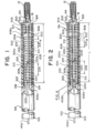
FIG. 1 an illustration of a delivery system and implant, according to aspects of the present invention. -
FIG. 2 is an illustration of another delivery system and implant, according to aspects of the present invention. -
FIG. 3 is an illustration of a suture linkage, according to aspects of the present invention. -
FIGS. 4A-4C are time-sequenced illustrations of forming a clove hitch knot, according to aspects of the present invention. -
FIGS. 5A-5B are illustrations of alternate pull wire linkages, according to aspects of the present invention. -
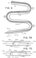
FIG. 6 is an illustration of a delivery system navigating a body lumen according to aspects of the present invention. -
FIGS. 7A-7D are illustrations of a proximal pull wire and a distal pull wire joined by a suture linkage such as illustrated inFIGS. 1-3 when the delivery system is navigated through turns in a body lumen such as illustrated inFIG. 6 according to aspects of the present invention. -
FIG. 8 is an illustration of embolic coils being positioned within an aneurysm according to aspects of the present invention. -
FIGS. 9A-9E illustrate a sequence of steps for releasing an embolic implant from the delivery member, according to aspects of the present invention. -
FIG. 10 is a flowchart of an example method of using the delivery member, according to aspects of the present invention. - The following description of certain examples of the invention should not be used to limit the scope of the present invention. The drawings, which are not necessarily to scale, depict selected embodiments and are not intended to limit the scope of the invention. The detailed description illustrates by way of example, not by way of limitation, the principles of the invention. Other examples, features, aspects, embodiments, and advantages of the invention will become apparent to those skilled in the pertinent art from the following description, which is by way of illustration, one of the best modes contemplated for carrying out the invention. As will be realized, the invention is capable of other different or equivalent aspects, all without departing from the invention. Accordingly, the drawings and descriptions should be regarded as illustrative in nature and not restrictive.
- Any one or more of the teachings, expressions, versions, examples, etc. described herein may be combined with any one or more of the other teachings, expressions, versions, examples, etc. that are described herein. The following-described teachings, expressions, versions, examples, etc. should therefore not be viewed in isolation relative to each other. Various suitable ways in which the teachings herein may be combined will be readily apparent to those skilled in the pertinent art in view of the teachings herein. Such modifications and variations are intended to be included within the scope of the claims.
- As used herein, the terms "about" or "approximately" for any numerical values or ranges indicate a suitable dimensional tolerance that allows the part or collection of components to function for its intended purpose as described herein. More specifically, "about" or "approximately" may refer to the range of values ±10% of the recited value, e.g. "about 90%" may refer to the range of values from 81% to 99%. In addition, as used herein, the terms "patient," "host," "user," and "subject" refer to any human or animal subject and are not intended to limit the systems or methods to human use, although use of the subject invention in a human patient represents a preferred embodiment.
- Turning to the figures, as illustrated in
FIGS. 1 and 2 anexample delivery member proximal tube 100, acoiled section 200a, adistal tube 300, asleeve 500 surrounding the coiled section, and a loop wire 400a, 400b, extending through the coiledsection 200a. Thedelivery member lumen 608 therethrough extending through theproximal tube 100, coiledsection 200a, anddistal tube 300. That is, theproximal tube 100 can have alumen 108 therethrough, the coiledsection 200a can have alumen 208 therethrough, thedistal tube 300 can have alumen 308 therethrough, and thelumens lumen 608 through thedelivery member proximal tube 100 can have adistal end 104 connected to aproximal end 202 of the coiledsection 200a and adistal end 204 of the coiledsection 200a can be connected to aproximal end 302 of thedistal tube 300. - The
distal tube 300 can include acompressible portion 306. Thecompressible portion 306 can be axially adjustable between an elongated condition and a compressed condition. Thecompressible portion 306 can be formed from a spiral-cut portion of thetube 300, formed by a laser cutting operation. Additionally, or alternatively, the compressible portion can be formed of a wound wire, spiral ribbon, or other arrangement allowing axial adjustment according to the present invention. Preferably,compressible portion 306 is in the elongated condition at rest and automatically or resiliently returns to the elongated condition from a compressed condition, unless otherwise constrained. - When the
delivery member section 200a andsleeve 500 can be more flexible than the distal hypotube and the proximal hypotube. One way to measure flexibility is to perform a three-point bend test wherein a portion of thedelivery member member delivery member section 200a and sleeve can be about 1.5 times more flexible than the distal hypotube and about 20 times more flexible than theproximal hypotube 100. That is, when the three-point test is performed identically on the threesections delivery member section 200a andsleeve 500 can be more flexible than the distal hypotube and the proximal hypotube as flexibility is determined by other means as would be known to a person of ordinary skill in the art. - The coiled section can be formed primarily of a non-radiopaque material such as steel and can include a
radiopaque section 216 made of a radiopaque material such as platinum and/or tungsten. Theradiopaque section 216 can be positioned between a proximal, non-radiopaque section of thecoil 212, and a distal, non-radiopaque section of thecoil 214. Theradiopaque section 216 can be positioned a predetermined distance from adistal end 304 of thedelivery member proximal section 212,radiopaque section 216, anddistal section 214 can be concentrically welded. -
Delivery members FIG. 1 and FIG. 2 are demonstrated to have a flexibility of about 25% to about 40% greater than competing delivery systems. - Comparing the
delivery member 10a illustrated inFIG. 1 to thedelivery member 10b illustrated inFIG. 2 , inFIG. 1 , the loop wire 400a is illustrated as having a first end attachment 406a to theproximal tube 100 and asecond end attachment 408a to thedistal tube 300 while, inFIG. 2 , the loop wire 400b is illustrated as having a first andsecond end attachment proximal tube 100. Although several factors can contribute to the flexibility of the delivery member, all else being equal, thedelivery member 10a illustrated inFIG. 1 can be more flexible compared to thedelivery member 10b illustrated inFIG. 2 because thedelivery member 10a illustrated inFIG. 1 has a single leg of loop wire 400a passing through the coiledsection 200a and therefore less material passing through the coiledsection 200a compared to thedelivery member 10b ofFIG. 2 , which has two legs of the loop wire 400b passing through the coiledsection 200a. Alternative configurations are also contemplated, for instance the loop wire need not have two separable ends, e.g., the legs of the loop wire can be fused, twisted, or otherwise formed as a single unit. - With respect to
FIGS. 1 and 2 , bothdelivery member proximal pull wire 140a and adistal pull wire 140b. Theproximal pull wire 140a anddistal pull wire 140b can be connected with asuture linkage 224, where theproximal pull wire 140a anddistal pull wire 140b are otherwise separate and not connected. Thesuture linkage 224 can include aproximal suture knot 222a that is attached to theproximal pull wire 140a and adistal suture knot 222b that is attached to thedistal pull wire 140b (collectively, suture knots 222). On a distal end ofproximal pull wire 140a can be disposed apull wire bead 220a. Similarly, on a proximal end ofdistal pull wire 140b can be disposed apull wire bead 220b (collectively pull wire beads 220). Thepull wire beads 220 can have a diameter larger than a diameter of thesuture knots 222. Accordingly, pullwire beads 220 can be effective to retain suture knots on thepull wires delivery member wire 140a can drift proximally in relation totubular body 90 ofdelivery member wire slack 226 is a distance betweendistal suture knot 222b and the distalpull wire bead 220b. As thedelivery member pull wire slack 226 is effective to prevent premature deployment ofimplant 12 fromdelivery member proximal pull wire 140a from affectingdistal pull wire 140b untilproximal pull wire 140a has been translated proximally by a distance L, which can be an overall length ofpull wire slack 226. According to some embodiments, and as discussed in more detail with respect toFIGS. 5A-5B ,suture linkage 224 can be provided in a variety of configurations. For example, rather than attaching suture linkage to pullwires suture linkage 224 can be a loop that is looped aroundpull wires wires wires wires -
FIG. 3 shows an exemplary suture linkage connectingpull wires suture linkage 224 can have an overall length L2 measured fromdistal suture knot 222b andproximal suture knot 222a. Pullwire slack 226 can have an overall length L1 that can be measured fromdistal suture knot 222b and distalpull wire bead 220b. -
FIGS. 4A-4C shows a time sequence of an exemplary method of formingsuture knots 222. According to some embodiments, suture knots can be provided as clove hitch knots. Clove hitch knots is a type of knot that is particularly useful when the position of the knot needs to be adjustable, because a clove hitch knot will loosen when slack is fed towards the knot from either direction. Accordingly a clove hitch knot can be movable along an object the clove knot is tied around. InFIG. 4A the first step of tying a clove hitch knot is shown. First, a free end of a rope is passed around a post the knot is to be attached to. InFIG. 4B , the second step is shown of crossing over the tied end of the rope and crossing over the post.FIG. 4C shows the working end of the rope being slipped under the wrap made in the second step, shown inFIG. 4B , thereby completing the clove hitch knot. -
FIGS. 5A-5B are illustrations of alternate pull wire linkages, according to aspects of the present invention.FIG. 5A shows an alternative suture linkage. Rather than being characterized bypull wire beads 220, in this embodiment both distal end ofpull wire 140a and proximal end ofpull wire 140b have a "J" shaped hooked end around which asuture linkage loop 224 of length L2 can be secured. In this configuration, pullwire slack 226 is formed ofpull wire slack 226a, which is a distance between the most proximal end ofsuture linkage 224 and the most distal end of the "J" hook ofpull wire 140a, and pullwire slack 226b, which is a distance between the most distal end ofsuture linkage 224 and the most proximal end of the "J" hook ofpull wire 140b. Accordingly, in this configuration, thepull wire slack 226 is a sum of the lengths ofpull wire slack 226a and pullwire slack 226b. -
FIG. 5B shows an alternative configuration ofpull wires pull wire 140a and the proximal end ofpull wire 140b have a "J" shaped hooked end which are wrapped around each other. That is, the distal end ofpull wire 140a and the proximal end ofdistal pull wire 140b can directly interface with each other. In this configuration, thepull wire slack 226 can have a length L1 that is measured between the most distal point ofpull wire 140a to the most proximal point ofwire 140b. The pull wire slack can be understood as the length L1 that theproximal pull wire 140a must be pulled before thedistal pull wire 140b begins to translate proximally with theproximal pull wire 140a as a single unit. -
FIG. 6 illustrates positioning of animplant 12 such as an embolic coil suitable for aneurysm treatment, aguide catheter 700, and adelivery system 10 including atubular body 90 and apull wire 140 within tortuous vasculature (vasculature not illustrated). At bends A, B, and C, thebody 90 can extend to a sidewall of theguide catheter 700 on each outer curve of each bend, and likewise, thepull wire 140 can extend to a sidewall of thebody 90 on each outer curve of each bend. During a procedure, thetubular body 90 and pullwire 140 can be fed into theguide catheter 700 in the distal direction D, first passing through bend A, then bend B, and then bend C. As thebody 90 and pullwire 140 navigate the bends, thedistal suture knot 222b may slide proximally alongdistal pull wire 140b by a distance less than pullwire slack 226 length L1. The pull wire slack can prevent the proximal translation in a proximal direction P ofdistal pull wire 140b with respect to thetubular body 90 of thedelivery member implant 12 from thedelivery member -
FIGS. 7A through 7D illustrate the progressive movement of thesuture linkage 224 as thedelivery system FIG. 6 .FIG. 7A illustrates the positioning of thesuture linkage 224 as thedistal end 94 of the tubular body approaches bend A.FIG. 7B illustrates the proximal movement of proximalpull wire portion 140a, which increases the gap betweenproximal pull wire 140a anddistal pull wire 140b as thedistal end 94 of the tubular body ofdelivery member FIG. 7C illustrates theproximal pull wire 140a moving further proximally with respect to thetubular body 90 ofdelivery member proximal pull wire 140a anddistal pull 140b, caused by the gradual proximal slide ofdistal suture knot 222b towards distalpull wire bead 220b asdistal end 94 of thetubular body 90 ofdelivery member FIG. 7D illustrates the moment beforedistal suture knot 222b engages to distalpull wire bead 220b as thedistal end 94 of thetubular body 90 ofdelivery member - Referring collectively to the illustrations in
FIGS. 6 and7A through 7D , as thedelivery member delivery member distal suture knot 222b can be free to move in the proximal and distal direction in relation to thetubular body 90. As illustrated,distal suture knot 222b can approach the distalpull wire bead 220b as thedelivery member FIGS. 7A through 7D indicate the proximal movement of theproximal pull wire 140a. - A gap L0, LA, LB, LC between
proximal pull wire 140a anddistal pull wire 140b can become progressively larger as illustrated inFIGS. 7A through 7D as thedelivery system FIG. 7B ,proximal suture knot 222a abuts proximalpull wire bead 220a, after which point further proximal translation of theproximal pull wire 140a causesdistal suture knot 222b to slide along distal pull wire, gradually reducing the distance betweendistal suture knot 222b and distalpull wire bead 220b. - As shown in
FIGS. 7A-7D , proximalpull wire bead 220a may have a diameter D1 and distalpull wire bead 220b may have a diameter D2. According to some embodiments, diameter D1 and diameter D2 may collectively be larger than a diameter oflumen 608 extending throughdelivery system pull wire bead 220b can be prevented from sliding past proximalpull wire bead 220a as thedelivery system FIG. 6 . Similarly, proximalpull wire bead 220a can be prevented from sliding past distalpull wire bead 220b as thedelivery system - Referring back to
FIGS. 1-2 , thedelivery member wire slack 226 that is measurable between thedistal suture knot 222b and the distalpull wire bead 220b. Thepull wire slack 226 can be of length L such that thedistal suture knot 222b is unlikely to engage the distalpull wire bead 220b as thedelivery member pull wire slack 226 can allow for greater strain relief at the distal end of thedistal pull wire 140b, thereby reducing the likelihood of premature deployment of a treatment device. The maximum length ofpull wire slack 226 can be limited by ease of manipulation of the proximal end of thedelivery member FIG. 2 that is several inches long. The length L ofpull wire slack 226 can therefore be sized to sufficiently relieve strain on the distal end of thedistal pull wire 140 to sufficiently reduce the likelihood of premature deployment of a treatment device and also to facilitate ease of manipulation of the delivery member during a treatment procedure. According to some embodiments, the length L ofpull wire slack 226 can be a length between approximately 2 mm and approximately 3 mm. -
FIG. 8 is an illustration ofembolic implant 12 being delivered throughcatheter 250 and positioned within an aneurysm A on a blood vessel BV. The implant can loop and bend with the aneurysm sac to form a thrombotic mass. The implant can loop back on themselves and/or loop next to other implants. As the aneurysm A becomes increasingly packed, overlapping portions of theimplant 12 can press into each other. -
FIGS. 9A-9E illustrate a time sequence of steps for releasing anembolic implant 12 from adelivery member 10. Thedelivery member 10 can be configured such as illustrated in the previous figures and as otherwise described herein.FIG. 9A illustrates an engagement system including theloop wire 400 anddistal pull wire 140b locked into a lockingportion 18 of themedical device 12. Thecompressible portion 306 of thedistal tube 300 can be compressed and theloop wire 400opening 405 at adistal end 404 of theloop wire 400 can be placed through the lockingportion 18. When thedistal pull wire 140b is put through theopening 405 themedical device 12 is now secure.FIG. 9B illustrates the predetermined length L1 of thepull wire slack 226 that prevents premature detachment ofimplant 12 asdelivery member wire slack 226 has been completely drawn tight, and further proximal translation ofproximal pull wire 140a will cause proximal translation ofdistal pull wire 140b, thereby releasingimplant 12 at a treatment site.FIG. 9C illustrates thedistal pull wire 140b being drawn proximally to begin the release sequence for themedical device 12.FIG. 9D illustrates the instant thedistal end 144 of the pull wire exits theopening 405 and thepull wire 140 is pulled free of theloop wire 400. Thedistal end 404 of theloop wire 400 falls away and exits the lockingportion 18. As can be seen, there is now nothing holding themedical device 12 to thedetachment system 10.FIG. 9E illustrates the end of the release sequence. Here, thecompressible portion 306 has extended/returned to its original shape and "sprung" forward. An elastic force E is imparted by the distal end 305 of thedistal tube 300 to theimplant 12 to "push" it away to ensure a clean separation and delivery of theimplant 12. - The
compressible portion 306 can have a difference in length (distance of compression) when measured in the compressed configuration and the original, uncompressed configuration of about 0.5 mm to about 0.75 mm. Greater elastic force E can be achieved by using a greater distance of compression. The distance of compression can be determined by the sizing of theloop wire 400, the shape of the lockingportion 18, and the shape of thedistal end 304 of thedistal tube 300. -
FIG. 10 is a flowchart of an example method of using the delivery member, according to aspects of the present invention. Inblock 1004, the method can include providing atubular body 90.Tubular body 90 includes alumen 608 extending therethrough and a compresseddistal portion 300. The method continues inblock 1008 by affixing a loop wire 400a, 400b to thetubular body 90. As shown inFIGS 1-2 , loop wire ends 406, 408 can be attached in a variety of configurations. In one configuration, as shown inFIG. 1 , loop wire end 406a is attached to aproximal tube 100 andloop wire end 408a is attached to a compresseddistal portion 300. In another configuration, as shown inFIG. 2 ,loop wire end proximal tube 100. Inblock 1012, the method can include compressing the compressibledistal portion 300. Inblock 1016, the loop opening 305 of theloop wire 400 can be positioned proximate thedistal end 306 of the compressibledistal portion 300. Inblock 1020 the method includes extending adistal pull wire 140b through a distal portion of thelumen 608 of thetubular body 90. Inblock 1024, the method can include extending aproximal pull wire 140a through a proximal portion of thelumen 608 of thetubular body 90. - In
optional block 1028, the method can include welding a proximalpull wire bead 220a on a distal end of theproximal pull wire 140a and a distalpull wire bead 220b on a proximal end of thedistal pull wire 140b. In some embodiments, a hooked "J" can be provided on distal end ofproximal pull wire 140a and a proximal end ofdistal pull wire 140b in lieu ofpull wire beads - In
block 1032, the method can include connecting theproximal pull wire 140a and thedistal pull wire 140b with asuture linkage 224. The suture linkage can include aproximal suture knot 222a that can be attached to a distal end of aproximal pull wire 140a and adistal suture knot 222b that can be attached to a proximal end of adistal pull wire 140b. - In
block 1036, the method can include extending aloop opening 405 through a lockingportion 18 of an implantablemedical device 12. Inblock 1040 the method can include extending a distal end of thedistal pull wire 140b through theloop opening 405. Inblock 1044, the method can include preventing proximal translation of thedistal pull wire 140b as the proximal pull wire is translated proximally with respect to thedistal pull wire 140b due to thepull wire slack 226 of thesuture linkage 224. Inblock 1048, the method can include facilitating proximal translation of thedistal pull wire 140b in response to theproximal pull wire 140a being translated by more than a predetermined length of thepull wire slack 226. - According to some embodiments, the method can include preventing premature deployment of the implantable
medical device 12 due to thepull wire slack 226 of thesuture linkage 224. In some embodiments, the method can include moving theloop wire 400 and thedistal pull wire 140b to release the implantablemedical device 12 from thedelivery system - According to some embodiments, the method can include, following proximal translation of the
proximal pull wire 140a by more than the predetermined length L1 of thepull wire slack 226, causing thedistal suture knot 222b to abut the distalpull wire bead 220b. Oncedistal suture knot 222b engages distalpull wire bead 220b, thedistal pull wire 140b and the proximal pull wire 104a can translate proximally as a unit. - In some embodiments, constructing the
tubular body 90 can include joining aflexible coil 200a between aproximal hypotube 100 and a compresseddistal portion 300 such that thelumen 608 extends from aproximal end 102 of theproximal hypotube 100, through theproximal hypotube 100, through theflexible coil 200a, through the compresseddistal portion 300, and to adistal end 304 of the compresseddistal portion 300. Flexible coil can be inhibited from elongating from the construction oftubular body 90. - In some embodiments, upon initial proximal translation of the
proximal pull wire 140a, thedistal pull wire 140b remains fixed in position while thedistal suture knot 222b slides along thedistal pull wire 140b for the predetermined length L1 of thepull wire slack 226. In some embodiments, the method can include translating theproximal pull wire 140a proximally for a distance longer than the predetermined length L1 to thereby deploy the implantablemedical device 12. - The descriptions contained herein are examples of embodiments of the invention and are not intended in any way to limit the scope of the invention. As described herein, the invention contemplates many variations and modifications of the implantation system and associated methods, including alternative geometries of system components, alternative materials, additional or alternative method steps, etc. Modifications apparent to those skilled in the pertinent art are intended to be within the scope of the claims which follow.
-
- 1. A delivery system for deploying an implantable medical device to a target location of a body vessel, the delivery system comprising:
- a tubular body comprising a lumen extending therethrough and a compressed distal portion;
- a loop wire comprising a first end affixed to the tubular body and comprising a loop opening positioned approximate the compressed distal portion;
- a pull wire extending through the lumen, the pull wire comprising
- a proximal pull wire portion;
- a distal pull wire portion, separate from the proximal pull wire portion; and
- a suture linkage connecting the proximal pull wire portion and the distal pull wire portion,
- the suture linkage comprising:
- a proximal suture knot slideably engaged to the proximal pull wire portion; and
- a distal suture knot slideably engaged to the distal pull wire portion.
- 2. The delivery system of aspect 1, wherein:
- a distal end of the proximal pull wire portion comprises a proximal pull wire bead and a proximal end of the distal pull wire portion comprises a distal pull wire bead,
- the proximal pull wire bead is configured to retain the proximal suture knot on the proximal pull wire portion during proximal translation of the proximal pull wire portion and the distal pull wire bead is configured to retain the distal suture knot on the distal pull wire portion during proximal translation of the distal pull wire portion,
- the loop wire and the distal pull wire portion are positioned to secure the implantable medical device to the delivery system;
- the suture linkage comprises pull wire slack that facilitates the proximal pull wire portion to be translated proximally with respect to the distal pull wire portion while the distal pull wire portion remains stationary for a predetermined length causing the distal suture knot to translate proximally to abut the distal pull wire bead such that when the distal suture knot abuts the distal pull wire bead both the proximal pull wire portion and distal pull wire portion translate proximally as a unit; and
- the pull wire slack is effective to inhibit premature deployment of the implantable medical device.
- 3. The delivery system of aspect 1, wherein the loop wire and the pull wire are movable to release the implantable medical device from the delivery system.
- 4. The delivery system of aspect 2, wherein the predetermined length of the pull wire slack comprises a length between approximately 2 mm and 3 mm.
- 5. The delivery system of aspect 2, wherein the suture linkage has a predetermined length that fits within the tubular body of the delivery system.
- 6. The delivery system of aspect 1, wherein the tubular body further comprises:
- a proximal hypotube;
- a flexible coil extending from a distal end of the proximal hypotube;
- the compressed distal portion extending from a distal end of the flexible coil; and
- wherein the lumen extends from a proximal end of the proximal hypotube, through the proximal hypotube, through the flexible coil, through the compressed distal portion, and to a distal end of the of the compressed distal portion.
- 7. The delivery system of aspect 6, further comprising a sleeve that extends along a majority of the of the flexible coil.
- 8. The delivery system of aspect 2, wherein upon initial proximal translation of the proximal pull wire portion, the distal pull wire portion remains fixed in position while the distal suture knot slides along the distal pull wire portion for the predetermined length of the pull wire slack.
- 9. The delivery system of aspect 2, wherein the proximal pull wire portion is translated proximally for a distance longer than the predetermined length to deploy the implantable medical device.
- 10. The delivery system of aspect 1, wherein each suture knot comprises a clove knot adapted to slide against the pull wire when the pull wire is translated proximally.
- 11. The delivery system of aspect 2, wherein the proximal pull wire bead comprises a first laser weld forming a diameter larger than a diameter of the proximal suture knot and the distal pull wire bead comprises a second laser weld forming a diameter larger than a diameter of the distal suture knot.
- 12. The delivery system of aspect 1, wherein the distal suture knot and the proximal suture knot each comprise a clove hitch knot.
- 13. A method comprising:
- providing a tubular body comprising a lumen extending therethrough and a compressed distal portion;
- affixing a loop wire to the tubular body;
- compressing the compressed distal portion;
- positioning a loop opening in the loop wire approximate a distal end of the compressed distal portion while the loop wire is affixed to the tubular body such that the loop wire is extended through the lumen;
- extending a distal pull wire portion through a distal portion of the lumen of the tubular body;
- extending a proximal pull wire portion, separate from the distal pull wire portion, through a proximal portion of the lumen of the tubular body;
- connecting the proximal pull wire portion and the distal pull wire portion with a suture linkage, the suture linkage comprising a proximal suture knot attached to the proximal pull wire portion and a distal suture knot attached to the distal pull wire portion, the proximal pull wire portion, suture linkage, and distal pull wire portion thereby forming a pull wire;
- extending the loop opening through a locking portion of an implantable medical device; and
- extending a distal end of the distal pull wire portion through the loop opening.
- 14. The method of aspect 13, further comprising:
- preventing proximal translation of the distal pull wire portion as the proximal pull wire portion is translated proximally with respect to the distal pull wire portion due to pull wire slack of the suture linkage;
- facilitating proximal translation of the distal pull wire portion in response to the proximal pull wire portion being translated proximally by more than a predetermined length of the pull wire slack, OR
- preventing premature deployment of the implantable medical device due to pull wire slack of the suture linkage, OR
- moving the loop wire and the distal pull wire portion to release the implantable medical device from the tubular body, OR
- constructing the tubular body by joining a flexible coil between a proximal hypotube and a distal hypotube comprising the compressed distal portion such that the lumen extends from a proximal end of the proximal hypotube, through the proximal hypotube, through the flexible coil, through the compressed distal portion, and to a distal end of the of the compressed distal portion and such that the flexible coil is inhibited from elongating..
- 15. The method of aspect 14:
- (i) further comprising welding a proximal pull wire bead on a distal end of the proximal pull wire portion and a distal pull wire bead on a proximal end of the distal pull wire portion; and
following proximal translation of the proximal pull wire portion by more than the predetermined length of the pull wire slack, causing the distal suture knot to abut the distal pull wire bead thereby causing the distal pull wire portion and the proximal pull wire portion to translate proximally as a unit, OR - (ii) wherein upon initial proximal translation of the proximal pull wire portion, the distal pull wire portion remains fixed in position while the distal suture knot slides along the distal pull wire portion for the predetermined length of the pull wire slack, OR
- (iii) further comprising translating the proximal pull wire portion proximally for a distance longer than the predetermined length, thereby deploying the implantable medical device.
- (i) further comprising welding a proximal pull wire bead on a distal end of the proximal pull wire portion and a distal pull wire bead on a proximal end of the distal pull wire portion; and
Claims (12)
- A delivery system for deploying an implantable medical device to a target location of a body vessel, the delivery system comprising:a tubular body comprising a lumen extending therethrough and a compressed distal portion;a loop wire comprising a first end affixed to the tubular body and comprising a loop opening positioned approximate the compressed distal portion;a pull wire extending through the lumen, the pull wire comprisinga proximal pull wire portion comprising a proximal pull wire hooked end;a distal pull wire portion comprising a distal pull wire hooked end, separate from the proximal pull wire portion; and one of the following options is fulfilled:a) a suture linkage loop is secured around the proximal pull wire hooked end and the distal pull wire hooked end; andb) the proximal pull wire hooked end and the distal pull wire hooked end are wrapped around each other.
- The delivery system of claim 1a), wherein:the proximal pull wire hooked end is configured to retain a proximal portion of the suture linkage loop on the proximal pull wire portion during proximal translation of the proximal pull wire hooked end and the distal pull wire hooked end is configured to retain a distal portion of the suture linkage loop on the distal pull wire portion during proximal translation of the distal pull wire portion,the loop wire and the distal pull wire hooked end are positioned to secure the implantable medical device to the delivery system;the suture linkage loop comprises pull wire slack that facilitates the proximal pull wire portion to be translated proximally with respect to the distal pull wire hooked end while the distal pull wire hooked end remains stationary for a predetermined length causing the distal portion of the suture linkage loop to translate proximally to abut a proximal-most end of the distal pull wire hooked end such that when the distal portion of the suture linkage loop abuts the proximal-most end of the distal pull wire hooked end both the proximal pull wire hooked end and distal pull wire hooked end translate proximally as a unit; andthe pull wire slack is effective to inhibit premature deployment of the implantable medical device.
- The delivery system of claim 1b), wherein:the loop wire and the distal pull wire hooked end are positioned to secure the implantable medical device to the delivery system;the proximal pull wire hooked end and the distal pull wire hooked end wrapped around each other comprises pull wire slack that facilitates the proximal pull wire hooked end to be translated proximally with respect to the distal pull wire hooked end while the distal pull wire hooked end remains stationary for a predetermined length causing a distal-most portion of the proximal pull wire hooked end to translate proximally to abut a proximal-most end of the distal pull wire hook portion such that when the distal-most portion of the proximal pulled wire hooked end abuts the proximal-most end of the distal pull wire hooked end, both the proximal pull wire hooked end and distal pull wire hooked end translate proximally as a unit; andthe pull wire slack is effective to inhibit premature deployment of the implantable medical device.
- The delivery system of any one of the preceding claims, wherein the loop wire and the pull wire are movable to release the implantable medical device from the delivery system.
- The delivery system of claim 2 or claim 3, or claim 4 when dependent on claim 2 or claim 3, wherein the predetermined length of the pull wire slack comprises a length between approximately 2 mm and 3 mm.
- The delivery system of claim 1a), or any one of claims 2, 4 and 5 when dependent on claim 1a), wherein the suture linkage loop has a predetermined length that fits within the tubular body of the delivery system.
- The delivery system of any one of the preceding claims, wherein the tubular body further comprises:a proximal hypotube;a flexible coil extending from a distal end of the proximal hypotube;the compressed distal portion extending from a distal end of the flexible coil; andwherein the lumen extends from a proximal end of the proximal hypotube, through the proximal hypotube, through the flexible coil, through the compressed distal portion, and to a distal end of the of the compressed distal portion.
- The delivery system of claim 6, further comprising a sleeve that extends along a majority of the of the flexible coil.
- The delivery system of any one of claims 2 and 4 to 8 when dependent on claim 1a), wherein upon initial proximal translation of the proximal pull wire hooked end, the distal pull wire hooked end remains fixed in position while the suture linkage loop slides along the distal pull wire hooked end for the predetermined length of the pull wire slack.
- The delivery system of any one of claims 3 to 8 when dependent on claim 1b), wherein upon initial proximal translation of the proximal pull wire hooked end, the distal pull wire hooked end remains fixed in position while the distal-most portion of the proximal pull wire hooked end slides along the distal pull hooked end for the predetermined length of the pull wire slack.
- The delivery system of any one of the preceding claims, wherein the proximal pull wire hooked end is translated proximally for a distance longer than the predetermined length to deploy the implantable medical device.
- The delivery system of any one of the preceding claims, wherein the distal pull wire hooked end and the proximal pull wire hooked end each comprise a J-shaped hook.
Applications Claiming Priority (2)
| Application Number | Priority Date | Filing Date | Title |
|---|---|---|---|
| US17/566,486 US11844490B2 (en) | 2021-12-30 | 2021-12-30 | Suture linkage for inhibiting premature embolic implant deployment |
| EP22217165.4A EP4205670B1 (en) | 2021-12-30 | 2022-12-29 | Suture linkage for inhibiting premature embolic implant deployment |
Related Parent Applications (1)
| Application Number | Title | Priority Date | Filing Date |
|---|---|---|---|
| EP22217165.4A Division EP4205670B1 (en) | 2021-12-30 | 2022-12-29 | Suture linkage for inhibiting premature embolic implant deployment |
Publications (2)
| Publication Number | Publication Date |
|---|---|
| EP4413933A2 true EP4413933A2 (en) | 2024-08-14 |
| EP4413933A3 EP4413933A3 (en) | 2024-10-02 |
Family
ID=84688963
Family Applications (2)
| Application Number | Title | Priority Date | Filing Date |
|---|---|---|---|
| EP24186079.0A Pending EP4413933A3 (en) | 2021-12-30 | 2022-12-29 | Suture linkage for inhibiting premature embolic implant deployment |
| EP22217165.4A Active EP4205670B1 (en) | 2021-12-30 | 2022-12-29 | Suture linkage for inhibiting premature embolic implant deployment |
Family Applications After (1)
| Application Number | Title | Priority Date | Filing Date |
|---|---|---|---|
| EP22217165.4A Active EP4205670B1 (en) | 2021-12-30 | 2022-12-29 | Suture linkage for inhibiting premature embolic implant deployment |
Country Status (6)
| Country | Link |
|---|---|
| US (2) | US11844490B2 (en) |
| EP (2) | EP4413933A3 (en) |
| JP (1) | JP2023099350A (en) |
| KR (1) | KR20230104020A (en) |
| CN (1) | CN116421250A (en) |
| ES (1) | ES2988684T3 (en) |
Citations (1)
| Publication number | Priority date | Publication date | Assignee | Title |
|---|---|---|---|---|
| US20200397444A1 (en) * | 2019-06-18 | 2020-12-24 | DePuy Synthes Products, Inc. | Pull wire detachment for intravascular devices |
Family Cites Families (263)
| Publication number | Priority date | Publication date | Assignee | Title |
|---|---|---|---|---|
| US3429408A (en) | 1967-04-25 | 1969-02-25 | Associated Spring Corp | Actuator sleeves for spring clutch |
| US5484409A (en) | 1989-08-25 | 1996-01-16 | Scimed Life Systems, Inc. | Intravascular catheter and method for use thereof |
| US5122136A (en) | 1990-03-13 | 1992-06-16 | The Regents Of The University Of California | Endovascular electrolytically detachable guidewire tip for the electroformation of thrombus in arteries, veins, aneurysms, vascular malformations and arteriovenous fistulas |
| US5108407A (en) | 1990-06-08 | 1992-04-28 | Rush-Presbyterian St. Luke's Medical Center | Method and apparatus for placement of an embolic coil |
| US5234437A (en) | 1991-12-12 | 1993-08-10 | Target Therapeutics, Inc. | Detachable pusher-vasoocclusion coil assembly with threaded coupling |
| US5636639A (en) | 1992-02-18 | 1997-06-10 | Symbiosis Corporation | Endoscopic multiple sample bioptome with enhanced biting action |
| US5263964A (en) | 1992-05-06 | 1993-11-23 | Coil Partners Ltd. | Coaxial traction detachment apparatus and method |
| US5350397A (en) | 1992-11-13 | 1994-09-27 | Target Therapeutics, Inc. | Axially detachable embolic coil assembly |
| US5250071A (en) | 1992-09-22 | 1993-10-05 | Target Therapeutics, Inc. | Detachable embolic coil assembly using interlocking clasps and method of use |
| US5382259A (en) | 1992-10-26 | 1995-01-17 | Target Therapeutics, Inc. | Vasoocclusion coil with attached tubular woven or braided fibrous covering |
| US5334210A (en) | 1993-04-09 | 1994-08-02 | Cook Incorporated | Vascular occlusion assembly |
| US5925059A (en) | 1993-04-19 | 1999-07-20 | Target Therapeutics, Inc. | Detachable embolic coil assembly |
| US5569221A (en) | 1994-07-07 | 1996-10-29 | Ep Technologies, Inc. | Catheter component bond and method |
| US6273404B1 (en) | 1995-06-05 | 2001-08-14 | Scimed Life Systems, Inc. | Method of making monolithic hub and strain relief |
| US6168622B1 (en) | 1996-01-24 | 2001-01-02 | Microvena Corporation | Method and apparatus for occluding aneurysms |
| US5899935A (en) | 1997-08-04 | 1999-05-04 | Schneider (Usa) Inc. | Balloon expandable braided stent with restraint |
| US6203547B1 (en) | 1997-12-19 | 2001-03-20 | Target Therapeutics, Inc. | Vaso-occlusion apparatus having a manipulable mechanical detachment joint and a method for using the apparatus |
| US6113622A (en) | 1998-03-10 | 2000-09-05 | Cordis Corporation | Embolic coil hydraulic deployment system |
| US6835185B2 (en) | 1998-12-21 | 2004-12-28 | Micrus Corporation | Intravascular device deployment mechanism incorporating mechanical detachment |
| US6391037B1 (en) | 2000-03-02 | 2002-05-21 | Prodesco, Inc. | Bag for use in the intravascular treatment of saccular aneurysms |
| US6723108B1 (en) | 2000-09-18 | 2004-04-20 | Cordis Neurovascular, Inc | Foam matrix embolization device |
| US6623504B2 (en) | 2000-12-08 | 2003-09-23 | Scimed Life Systems, Inc. | Balloon catheter with radiopaque distal tip |
| DE60224502T2 (en) | 2001-01-10 | 2008-12-24 | Cordis Neurovascular, Inc., Miami Lakes | System for introducing an embolic coil |
| US6454780B1 (en) | 2001-06-21 | 2002-09-24 | Scimed Life Systems, Inc. | Aneurysm neck obstruction device |
| WO2003004086A2 (en) | 2001-07-05 | 2003-01-16 | Precision Vascular Systems, Inc. | Troqueable soft tip medical device and method of usage |
| US8715312B2 (en) | 2001-07-20 | 2014-05-06 | Microvention, Inc. | Aneurysm treatment device and method of use |
| US8252040B2 (en) | 2001-07-20 | 2012-08-28 | Microvention, Inc. | Aneurysm treatment device and method of use |
| EP1450900B1 (en) | 2001-12-03 | 2006-07-26 | Ekos Corporation | Small vessel ultrasound catheter |
| US20030195553A1 (en) | 2002-04-12 | 2003-10-16 | Scimed Life Systems, Inc. | System and method for retaining vaso-occlusive devices within an aneurysm |
| US7608058B2 (en) | 2002-07-23 | 2009-10-27 | Micrus Corporation | Stretch resistant therapeutic device |
| US8425549B2 (en) | 2002-07-23 | 2013-04-23 | Reverse Medical Corporation | Systems and methods for removing obstructive matter from body lumens and treating vascular defects |
| US7208003B2 (en) | 2002-09-20 | 2007-04-24 | Cordis Neurovascular, Inc. | Reattachable introducer for a medical device deployment system |
| FR2853521B1 (en) | 2003-04-10 | 2005-12-02 | Claude Mialhe | DEVICE FOR EXPANDING A VESSEL AND INTRODUCING VASCULAR IMPLANT |
| US7371228B2 (en) | 2003-09-19 | 2008-05-13 | Medtronic Vascular, Inc. | Delivery of therapeutics to treat aneurysms |
| US8182544B2 (en) | 2003-10-08 | 2012-05-22 | Codman & Shurtleff, Inc. | Method for placing a medical agent into a vessel of the body |
| US9308382B2 (en) | 2004-06-10 | 2016-04-12 | Medtronic Urinary Solutions, Inc. | Implantable pulse generator systems and methods for providing functional and/or therapeutic stimulation of muscles and/or nerves and/or central nervous system tissue |
| US20060025801A1 (en) | 2004-07-30 | 2006-02-02 | Robert Lulo | Embolic device deployment system with filament release |
| US9655633B2 (en) | 2004-09-10 | 2017-05-23 | Penumbra, Inc. | System and method for treating ischemic stroke |
| CA2581272A1 (en) | 2004-09-22 | 2006-05-18 | Lee R. Guterman | Cranial aneurysm treatment arrangement |
| US20060089637A1 (en) | 2004-10-14 | 2006-04-27 | Werneth Randell L | Ablation catheter |
| DE602004010276D1 (en) | 2004-11-10 | 2008-01-03 | Creganna Technologies Ltd | Introducer catheter assembly for stents |
| US8562672B2 (en) | 2004-11-19 | 2013-10-22 | Medtronic, Inc. | Apparatus for treatment of cardiac valves and method of its manufacture |
| US20060116714A1 (en) | 2004-11-26 | 2006-06-01 | Ivan Sepetka | Coupling and release devices and methods for their assembly and use |
| US8425550B2 (en) | 2004-12-01 | 2013-04-23 | Boston Scientific Scimed, Inc. | Embolic coils |
| US7608089B2 (en) | 2004-12-22 | 2009-10-27 | Boston Scientific Scimed, Inc. | Vaso-occlusive device having pivotable coupling |
| US20060206139A1 (en) | 2005-01-19 | 2006-09-14 | Tekulve Kurt J | Vascular occlusion device |
| US7985238B2 (en) * | 2005-06-02 | 2011-07-26 | Codman & Shurtleff, Inc. | Embolic coil delivery system with spring wire release mechanism |
| US7799052B2 (en) | 2005-06-02 | 2010-09-21 | Codman & Shurtleff, Inc. | Stretch resistant embolic coil delivery system with mechanical release mechanism |
| US7819891B2 (en) | 2005-06-02 | 2010-10-26 | Codman & Shurtleff, Inc. | Stretch resistant embolic coil delivery system with spring release mechanism |
| US7819892B2 (en) | 2005-06-02 | 2010-10-26 | Codman & Shurtleff, Inc. | Embolic coil delivery system with spring wire release mechanism |
| US20060276826A1 (en) | 2005-06-02 | 2006-12-07 | Vladimir Mitelberg | Stretch resistant embolic coil delivery system with mechanical release mechanism |
| US7367987B2 (en) | 2005-06-02 | 2008-05-06 | Cordis Neurovascular, Inc. | Stretch resistant embolic coil delivery system with mechanical release mechanism |
| US7377932B2 (en) | 2005-06-02 | 2008-05-27 | Cordis Neurovascular, Inc. | Embolic coil delivery system with mechanical release mechanism |
| US20060276833A1 (en) | 2005-06-02 | 2006-12-07 | Keith Balgobin | Stretch resistant embolic coil delivery system with spring assisted release mechanism |
| US20060276830A1 (en) | 2005-06-02 | 2006-12-07 | Keith Balgobin | Stretch resistant embolic coil delivery system with mechanical release mechanism |
| US7811305B2 (en) | 2005-06-02 | 2010-10-12 | Codman & Shurtleff, Inc. | Stretch resistant embolic coil delivery system with spring release mechanism |
| US7708754B2 (en) | 2005-06-02 | 2010-05-04 | Codman & Shurtleff, Pc | Stretch resistant embolic coil delivery system with mechanical release mechanism |
| US7708755B2 (en) | 2005-06-02 | 2010-05-04 | Codman & Shurtleff Inc. | Stretch resistant embolic coil delivery system with combined mechanical and pressure release mechanism |
| US7371251B2 (en) | 2005-06-02 | 2008-05-13 | Cordis Neurovascular, Inc. | Stretch resistant embolic coil delivery system with mechanical release mechanism |
| US20060276825A1 (en) | 2005-06-02 | 2006-12-07 | Vladimir Mitelberg | Stretch resistant embolic coil delivery system with mechanical release mechanism |
| US7371252B2 (en) | 2005-06-02 | 2008-05-13 | Cordis Neurovascular, Inc. | Stretch resistant embolic coil delivery system with mechanical release mechanism |
| US9636115B2 (en) | 2005-06-14 | 2017-05-02 | Stryker Corporation | Vaso-occlusive delivery device with kink resistant, flexible distal end |
| CN101309651B (en) | 2005-06-20 | 2011-12-07 | 麦德托尼克消融前沿有限公司 | Ablation catheter |
| US20070083132A1 (en) | 2005-10-11 | 2007-04-12 | Sharrow James S | Medical device coil |
| CA2630021C (en) | 2005-11-17 | 2013-08-13 | Microvention, Inc. | Three-dimensional complex coil |
| US9757260B2 (en) | 2006-03-30 | 2017-09-12 | Medtronic Vascular, Inc. | Prosthesis with guide lumen |
| US7766933B2 (en) | 2006-03-31 | 2010-08-03 | Codman & Shurtleff, Inc. | Stretch resistant design for embolic coils with stabilization bead |
| US9615832B2 (en) | 2006-04-07 | 2017-04-11 | Penumbra, Inc. | Aneurysm occlusion system and method |
| US8777979B2 (en) | 2006-04-17 | 2014-07-15 | Covidien Lp | System and method for mechanically positioning intravascular implants |
| CA2649702C (en) * | 2006-04-17 | 2014-12-09 | Microtherapeutics, Inc. | System and method for mechanically positioning intravascular implants |
| JP2010500917A (en) | 2006-06-15 | 2010-01-14 | マイクロベンション, インコーポレイテッド | Embolization device composed of expandable polymer |
| US8366720B2 (en) | 2006-07-31 | 2013-02-05 | Codman & Shurtleff, Inc. | Interventional medical device system having an elongation retarding portion and method of using the same |
| US8062325B2 (en) | 2006-07-31 | 2011-11-22 | Codman & Shurtleff, Inc. | Implantable medical device detachment system and methods of using the same |
| US7901444B2 (en) | 2006-09-29 | 2011-03-08 | Codman & Shurtleff, Inc. | Embolic coil delivery system with mechanical release mechanism |
| WO2008064209A1 (en) | 2006-11-20 | 2008-05-29 | Boston Scientific Scimed, Inc. | Mechanically detachable vaso-occlusive device |
| WO2008064205A2 (en) | 2006-11-20 | 2008-05-29 | Boston Scientific Limited | Mechanically detachable vaso-occlusive device |
| US8926650B2 (en) | 2006-11-20 | 2015-01-06 | Boston Scientific Scimed, Inc. | Mechanically detachable vaso-occlusive device |
| US20080281350A1 (en) | 2006-12-13 | 2008-11-13 | Biomerix Corporation | Aneurysm Occlusion Devices |
| US8197442B2 (en) | 2007-04-27 | 2012-06-12 | Codman & Shurtleff, Inc. | Interventional medical device system having a slotted section and radiopaque marker and method of making the same |
| US8864789B2 (en) | 2007-04-27 | 2014-10-21 | DePuy Synthes Products, LLC | Interventional medical device system having a spiral section and radiopaque marker and method of making the same |
| AU2008254770A1 (en) | 2007-05-18 | 2008-11-27 | Stryker Corporation | Medical implant detachment systems |
| DE102007038446A1 (en) | 2007-08-14 | 2009-02-19 | pfm Produkte für die Medizin AG | Embolisiereinrichtung |
| US20090099592A1 (en) | 2007-10-15 | 2009-04-16 | Boston Scientific Scimed, Inc. | Detachable Interlock Systems and Methods of Use |
| AU2008345590B2 (en) | 2007-12-21 | 2014-10-30 | Microvention, Inc. | Hydrogel filaments for biomedical uses |
| US8974518B2 (en) | 2008-03-25 | 2015-03-10 | Medtronic Vascular, Inc. | Eversible branch stent-graft and deployment method |
| JP5610542B2 (en) | 2008-04-21 | 2014-10-22 | コヴィディエン リミテッド パートナーシップ | Blade ball embolization device and delivery system |
| EP2192947A1 (en) | 2008-04-30 | 2010-06-09 | Medtronic, Inc. | Techniques for placing medical leads for electrical stimulation of nerve tissue |
| US20090312748A1 (en) | 2008-06-11 | 2009-12-17 | Johnson Kirk L | Rotational detachment mechanism |
| US8070694B2 (en) | 2008-07-14 | 2011-12-06 | Medtronic Vascular, Inc. | Fiber based medical devices and aspiration catheters |
| US8333796B2 (en) | 2008-07-15 | 2012-12-18 | Penumbra, Inc. | Embolic coil implant system and implantation method |
| US9232992B2 (en) | 2008-07-24 | 2016-01-12 | Aga Medical Corporation | Multi-layered medical device for treating a target site and associated method |
| US8721714B2 (en) | 2008-09-17 | 2014-05-13 | Medtronic Corevalve Llc | Delivery system for deployment of medical devices |
| JP5483377B2 (en) | 2008-10-13 | 2014-05-07 | ストライカー コーポレイション | Vascular closure coil supply system |
| US8758847B2 (en) | 2009-02-18 | 2014-06-24 | AUST Development, LLC | Apparatus and methods for making coated liners and tubular devices including such liners |
| US9717500B2 (en) | 2009-04-15 | 2017-08-01 | Microvention, Inc. | Implant delivery system |
| CN102438533B (en) | 2009-04-20 | 2014-11-26 | 加奇生物科技(上海)有限公司 | Delivery assembly for occlusion device using mechanical interlocking coupling mechanism |
| US8758423B2 (en) | 2009-06-18 | 2014-06-24 | Graftcraft I Goteborg Ab | Device and method for treating ruptured aneurysms |
| US9474532B2 (en) | 2009-09-09 | 2016-10-25 | Kaneka Corporation | Embolization coil |
| US9956100B2 (en) | 2009-09-15 | 2018-05-01 | Brightwater Medical, Inc. | Systems and methods for coupling and decoupling a catheter |
| WO2011038017A1 (en) | 2009-09-22 | 2011-03-31 | Penumbra, Inc. | Manual actuation system for deployment of implant |
| KR20110043799A (en) | 2009-10-16 | 2011-04-28 | 강호창 | Microcoil assembly |
| US9095342B2 (en) | 2009-11-09 | 2015-08-04 | Covidien Lp | Braid ball embolic device features |
| US20110118776A1 (en) | 2009-11-18 | 2011-05-19 | Boston Scientific Scimed, Inc. | Delivery wire assembly for occlusive device delivery system |
| CN102188300B (en) | 2010-03-02 | 2014-05-28 | 上海微创医疗器械(集团)有限公司 | Aneurismal surgical device |
| KR20130054952A (en) | 2010-04-14 | 2013-05-27 | 마이크로벤션, 인코포레이티드 | Implant delivery device |
| US8764811B2 (en) | 2010-04-20 | 2014-07-01 | Medtronic Vascular, Inc. | Controlled tip release stent graft delivery system and method |
| US8876878B2 (en) | 2010-07-23 | 2014-11-04 | Medtronic, Inc. | Attachment mechanism for stent release |
| US8616040B2 (en) | 2010-09-17 | 2013-12-31 | Medtronic Vascular, Inc. | Method of forming a drug-eluting medical device |
| US9039749B2 (en) | 2010-10-01 | 2015-05-26 | Covidien Lp | Methods and apparatuses for flow restoration and implanting members in the human body |
| KR20140004679A (en) | 2010-12-20 | 2014-01-13 | 마이크로벤션, 인코포레이티드 | Polymer stents and methods of manufacture |
| US20120172913A1 (en) | 2010-12-30 | 2012-07-05 | Cook Medical Technologies Llc | Delivery of an embolization coil with an attacher |
| US20120283768A1 (en) | 2011-05-05 | 2012-11-08 | Sequent Medical Inc. | Method and apparatus for the treatment of large and giant vascular defects |
| US9486604B2 (en) | 2011-05-12 | 2016-11-08 | Medtronic, Inc. | Packaging and preparation tray for a delivery system |
| GB2511375B (en) | 2011-05-13 | 2017-07-26 | Spiration Inc | Deployment Catheter |
| US8795241B2 (en) | 2011-05-13 | 2014-08-05 | Spiration, Inc. | Deployment catheter |
| WO2012158668A1 (en) | 2011-05-17 | 2012-11-22 | Stryker Corporation | Method of fabricating an implantable medical device that includes one or more thin film polymer support layers |
| WO2012166467A1 (en) | 2011-05-27 | 2012-12-06 | Stryker Corporation | Assembly for percutaneously inserting an implantable medical device, steering the device to a target location and deploying the device |
| US9750565B2 (en) | 2011-09-30 | 2017-09-05 | Medtronic Advanced Energy Llc | Electrosurgical balloons |
| KR101315443B1 (en) | 2011-12-02 | 2013-10-07 | 강호창 | Micro-coil assembly |
| EP3156006B1 (en) | 2012-03-16 | 2022-05-18 | Terumo Corporation | Stent and stent delivery device |
| US9833625B2 (en) | 2012-03-26 | 2017-12-05 | Medtronic, Inc. | Implantable medical device delivery with inner and outer sheaths |
| US9717421B2 (en) | 2012-03-26 | 2017-08-01 | Medtronic, Inc. | Implantable medical device delivery catheter with tether |
| US9155540B2 (en) | 2012-03-30 | 2015-10-13 | DePuy Synthes Products, Inc. | Embolic coil detachment mechanism with heating element and kicker |
| US9242290B2 (en) | 2012-04-03 | 2016-01-26 | Medtronic Vascular, Inc. | Method and apparatus for creating formed elements used to make wound stents |
| US9700399B2 (en) | 2012-04-26 | 2017-07-11 | Medtronic Vascular, Inc. | Stopper to prevent graft material slippage in a closed web stent-graft |
| US9549832B2 (en) | 2012-04-26 | 2017-01-24 | Medtronic Vascular, Inc. | Apparatus and methods for filling a drug eluting medical device via capillary action |
| GB2501714B (en) | 2012-05-02 | 2014-05-07 | Cook Medical Technologies Llc | Implant delivery system |
| EP2668915A1 (en) | 2012-06-01 | 2013-12-04 | Acandis GmbH & Co. KG | System for delivering a stretch resistant vaso-occlusive device and a method of producing same |
| US10124087B2 (en) | 2012-06-19 | 2018-11-13 | Covidien Lp | Detachable coupling for catheter |
| US9149190B2 (en) | 2012-07-17 | 2015-10-06 | Stryker Corporation | Notification system of deviation from predefined conditions |
| US9770251B2 (en) | 2012-08-13 | 2017-09-26 | Microvention, Inc. | Shaped removal device |
| US20140058435A1 (en) | 2012-08-21 | 2014-02-27 | Donald K. Jones | Implant delivery and release system |
| US9504476B2 (en) | 2012-10-01 | 2016-11-29 | Microvention, Inc. | Catheter markers |
| WO2014062696A1 (en) | 2012-10-15 | 2014-04-24 | Microvention, Inc. | Polymeric treatment compositions |
| US20140135811A1 (en) | 2012-11-13 | 2014-05-15 | Covidien Lp | Occlusive devices |
| US9539022B2 (en) | 2012-11-28 | 2017-01-10 | Microvention, Inc. | Matter conveyance system |
| US9826963B2 (en) | 2012-12-07 | 2017-11-28 | Medtronic, Inc. | Minimally invasive implantable neurostimulation system |
| US9943313B2 (en) | 2013-01-03 | 2018-04-17 | Empirilon Technology Llc | Detachable coil release system and handle assembly |
| US10342546B2 (en) | 2013-01-14 | 2019-07-09 | Microvention, Inc. | Occlusive device |
| US9949739B2 (en) | 2013-02-27 | 2018-04-24 | Microvention, Inc. | Integral wiping system and method |
| US9539382B2 (en) | 2013-03-12 | 2017-01-10 | Medtronic, Inc. | Stepped catheters with flow restrictors and infusion systems using the same |
| US9451964B2 (en) | 2013-03-14 | 2016-09-27 | Stryker Corporation | Vaso-occlusive device delivery system |
| EP2967573B1 (en) | 2013-03-14 | 2021-04-21 | Stryker Corporation | Vaso-occlusive device delivery system |
| US10149676B2 (en) | 2013-03-14 | 2018-12-11 | Incumedx, Inc. | Implants, methods of manufacturing the same, and devices and methods for delivering the implants to a vascular disorder of a patient |
| WO2014159584A2 (en) | 2013-03-14 | 2014-10-02 | Stryker Corporation | Vaso-occlusive device delivery system |
| US10076336B2 (en) | 2013-03-15 | 2018-09-18 | Covidien Lp | Delivery and detachment mechanisms for vascular implants |
| WO2014144980A1 (en) | 2013-03-15 | 2014-09-18 | Covidien Lp | Occlusive device |
| CN105377184B (en) | 2013-03-15 | 2017-06-30 | 微仙美国有限公司 | embolic protection device |
| US9398966B2 (en) | 2013-03-15 | 2016-07-26 | Medtronic Vascular, Inc. | Welded stent and stent delivery system |
| WO2014151123A1 (en) | 2013-03-15 | 2014-09-25 | Microvention, Inc. | Multi-component obstruction removal system and method |
| WO2014174437A1 (en) | 2013-04-22 | 2014-10-30 | Sandvik Intellectual Property Ab | Method for drug loading hydroxyapatite coated implant surfaces |
| US9445928B2 (en) | 2013-05-30 | 2016-09-20 | Medtronic Vascular, Inc. | Delivery system having a single handed deployment handle for a retractable outer sheath |
| US11291452B2 (en) | 2013-06-26 | 2022-04-05 | W. L. Gore & Associates, Inc. | Medical device deployment system |
| US10953193B2 (en) | 2013-07-16 | 2021-03-23 | Covidien Lp | Microcatheter with modified PTFE liner |
| US9662120B2 (en) | 2013-08-23 | 2017-05-30 | Cook Medical Technologies Llc | Detachable treatment device delivery system utilizing compression at attachment zone |
| US9675782B2 (en) | 2013-10-10 | 2017-06-13 | Medtronic Vascular, Inc. | Catheter pull wire actuation mechanism |
| US9955978B2 (en) | 2013-10-25 | 2018-05-01 | Medtronic Vascular, Inc. | Tissue compression device with multi-chamber bladder |
| US9808599B2 (en) | 2013-12-20 | 2017-11-07 | Microvention, Inc. | Device delivery system |
| JP6412137B2 (en) | 2013-12-20 | 2018-10-24 | マイクロベンション インコーポレイテッドMicrovention, Inc. | Discharge adapter |
| US9566072B2 (en) | 2013-12-27 | 2017-02-14 | Blockade Medical, LLC | Coil system |
| US9788839B2 (en) | 2014-02-14 | 2017-10-17 | Cook Medical Technologies Llc | Stable screw-type detachment mechanism |
| CN106163459B (en) | 2014-04-08 | 2018-05-29 | 斯瑞克公司 | Implantation material delivery system |
| WO2015167997A1 (en) | 2014-04-30 | 2015-11-05 | Stryker Corporation | Implant delivery system and method of use |
| US9060777B1 (en) | 2014-05-28 | 2015-06-23 | Tw Medical Technologies, Llc | Vaso-occlusive devices and methods of use |
| US9668898B2 (en) | 2014-07-24 | 2017-06-06 | Medtronic Vascular, Inc. | Stent delivery system having dynamic deployment and methods of manufacturing same |
| ES2726910T3 (en) | 2014-07-25 | 2019-10-10 | Incumedx Inc | Covered embolic coils |
| US9918718B2 (en) | 2014-08-08 | 2018-03-20 | DePuy Synthes Products, Inc. | Embolic coil delivery system with retractable mechanical release mechanism |
| US9770577B2 (en) | 2014-09-15 | 2017-09-26 | Medtronic Xomed, Inc. | Pressure relief for a catheter balloon device |
| RU2721288C2 (en) | 2014-09-17 | 2020-05-18 | Метэктив Медикал, Инк. | Medical device for saccular aneurysm treatment |
| US9579484B2 (en) | 2014-09-19 | 2017-02-28 | Medtronic Vascular, Inc. | Sterile molded dispenser |
| GB2533087B (en) | 2014-12-08 | 2018-08-08 | Cook Medical Technologies Llc | Medical implant detachment mechanism and introducer assembly |
| US10857012B2 (en) | 2015-01-20 | 2020-12-08 | Neurogami Medical, Inc. | Vascular implant |
| US10925611B2 (en) | 2015-01-20 | 2021-02-23 | Neurogami Medical, Inc. | Packaging for surgical implant |
| US11484319B2 (en) | 2015-01-20 | 2022-11-01 | Neurogami Medical, Inc. | Delivery system for micrograft for treating intracranial aneurysms |
| EP3247285B1 (en) | 2015-01-20 | 2021-08-11 | Neurogami Medical, Inc. | Micrograft for the treatment of intracranial aneurysms |
| US9692557B2 (en) | 2015-02-04 | 2017-06-27 | Stryker European Holdings I, Llc | Apparatus and methods for administering treatment within a bodily duct of a patient |
| US10888331B2 (en) | 2015-02-10 | 2021-01-12 | Boston Scientific Scimed, Inc. | Active release of embolic coils |
| JP6780637B2 (en) | 2015-03-03 | 2020-11-04 | 株式会社カネカメディックス | Vascular embolus tool and its manufacturing method |
| WO2016154632A1 (en) | 2015-03-26 | 2016-09-29 | Boston Scientific Scimed, Inc. | Embolic coil delivery system with easy-release knot |
| WO2016178171A1 (en) | 2015-05-07 | 2016-11-10 | The Medical Research Infrastructure And Health Services Fund Of The Tel-Aviv Medical Center | Temporary interatrial shunts |
| US9717503B2 (en) | 2015-05-11 | 2017-08-01 | Covidien Lp | Electrolytic detachment for implant delivery systems |
| US10398874B2 (en) | 2015-05-29 | 2019-09-03 | Covidien Lp | Catheter distal tip configuration |
| US10154905B2 (en) | 2015-08-07 | 2018-12-18 | Medtronic Vascular, Inc. | System and method for deflecting a delivery catheter |
| US10307168B2 (en) | 2015-08-07 | 2019-06-04 | Terumo Corporation | Complex coil and manufacturing techniques |
| US10492938B2 (en) | 2015-08-11 | 2019-12-03 | Terumo Corporation | System and method for implant delivery |
| US20200147347A1 (en) | 2015-09-15 | 2020-05-14 | Orbusneich Medical Pte. Ltd. | Vascular re-entry catheter |
| WO2017049212A1 (en) | 2015-09-18 | 2017-03-23 | Microvention, Inc. | Vessel prosthesis |
| EP3349671B1 (en) | 2015-09-18 | 2024-01-24 | Terumo Corporation | Pushable implant delivery system |
| EP3349689B1 (en) | 2015-09-18 | 2023-12-27 | Microvention, Inc. | Implant retention, detachment, and delivery system |
| WO2017049312A1 (en) | 2015-09-18 | 2017-03-23 | Microvention, Inc. | Releasable delivery system |
| EP3352689B1 (en) | 2015-09-21 | 2018-12-26 | Stryker Corporation | Embolectomy devices |
| CN108135626B (en) | 2015-09-21 | 2021-02-12 | 斯瑞克公司 | Thrombus taking device |
| US10172632B2 (en) | 2015-09-22 | 2019-01-08 | Medtronic Vascular, Inc. | Occlusion bypassing apparatus with a re-entry needle and a stabilization tube |
| WO2017062572A1 (en) | 2015-10-06 | 2017-04-13 | Boston Scientific Scimed, Inc. | Pusher arm and ball release mechanism for embolic coils |
| US20170100143A1 (en) | 2015-10-07 | 2017-04-13 | Stryker Corporation | Multiple barrel clot removal devices |
| US10327791B2 (en) | 2015-10-07 | 2019-06-25 | Medtronic Vascular, Inc. | Occlusion bypassing apparatus with a re-entry needle and a distal stabilization balloon |
| US10786302B2 (en) | 2015-10-09 | 2020-09-29 | Medtronic, Inc. | Method for closure and ablation of atrial appendage |
| EP3302303A4 (en) | 2015-10-14 | 2018-07-04 | Three Rivers Medical Inc. | Mechanical embolization delivery apparatus and methods |
| US10271873B2 (en) | 2015-10-26 | 2019-04-30 | Medtronic Vascular, Inc. | Sheathless guide catheter assembly |
| US11090055B2 (en) | 2015-10-30 | 2021-08-17 | Incumedx Inc. | Devices and methods for delivering an implant to a vascular disorder |
| WO2017087816A1 (en) | 2015-11-19 | 2017-05-26 | Penumbra, Inc. | Systems and methods for treatment of stroke |
| US10631946B2 (en) | 2015-11-30 | 2020-04-28 | Penumbra, Inc. | System for endoscopic intracranial procedures |
| EP3386580B1 (en) | 2015-12-09 | 2023-11-01 | Medtronic Vascular Inc. | Catheter with a lumen shaped as an identification symbol |
| US10159568B2 (en) | 2015-12-14 | 2018-12-25 | Medtronic, Inc. | Delivery system having retractable wires as a coupling mechanism and a deployment mechanism for a self-expanding prosthesis |
| US10500046B2 (en) | 2015-12-14 | 2019-12-10 | Medtronic, Inc. | Delivery system having retractable wires as a coupling mechanism and a deployment mechanism for a self-expanding prosthesis |
| CN108472043B (en) | 2015-12-30 | 2022-05-31 | 斯瑞克公司 | Embolization device and method of making same |
| US20170189033A1 (en) | 2016-01-06 | 2017-07-06 | Microvention, Inc. | Occlusive Embolic Coil |
| US10070950B2 (en) | 2016-02-09 | 2018-09-11 | Medtronic Vascular, Inc. | Endoluminal prosthetic assemblies, and associated systems and methods for percutaneous repair of a vascular tissue defect |
| CN109069796B (en) | 2016-02-10 | 2021-07-30 | 微仙美国有限公司 | Intravascular treatment site entry |
| AU2017218115B2 (en) | 2016-02-10 | 2020-03-05 | Microvention, Inc. | Devices for vascular occlusion |
| US10188500B2 (en) | 2016-02-12 | 2019-01-29 | Medtronic Vascular, Inc. | Stent graft with external scaffolding and method |
| US10485579B2 (en) | 2016-02-25 | 2019-11-26 | Indian Wells Medical, Inc. | Steerable endoluminal punch |
| US20170258476A1 (en) | 2016-03-08 | 2017-09-14 | Terumo Kabushiki Kaisha | Blood vessel treatment method |
| AU2017240507B2 (en) | 2016-03-31 | 2020-01-30 | Medtronic Vascular Inc. | Expandable introducer sheath having a steering mechanism |
| WO2017172735A1 (en) | 2016-03-31 | 2017-10-05 | 1/1Medtronic Vascular Inc. | Endoluminal prosthetic devices having fluid-absorbable compositions for repair of a vascular tissue defect |
| US10695542B2 (en) | 2016-04-04 | 2020-06-30 | Medtronic Vascular, Inc. | Drug coated balloon |
| US10252024B2 (en) | 2016-04-05 | 2019-04-09 | Stryker Corporation | Medical devices and methods of manufacturing same |
| US10441407B2 (en) | 2016-04-12 | 2019-10-15 | Medtronic Vascular, Inc. | Gutter filling stent-graft and method |
| US9987122B2 (en) | 2016-04-13 | 2018-06-05 | Medtronic Vascular, Inc. | Iliac branch device and method |
| US10010403B2 (en) | 2016-04-18 | 2018-07-03 | Medtronic Vascular, Inc. | Stent-graft prosthesis and method of manufacture |
| US20170304097A1 (en) | 2016-04-21 | 2017-10-26 | Medtronic Vascular, Inc. | Stent-graft delivery system having an inner shaft component with a loading pad or covering on a distal segment thereof for stent retention |
| WO2017189615A1 (en) | 2016-04-25 | 2017-11-02 | Stryker Corporation | Clot-engulfing mechanical thrombectomy apparatuses |
| WO2017189591A1 (en) | 2016-04-25 | 2017-11-02 | Stryker Corporation | Inverting mechanical thrombectomy apparatuses and methods of use in the vasculature |
| CN109890304B (en) | 2016-04-25 | 2021-11-09 | 斯瑞克公司 | Anti-blocking and macerating thrombus removal device and method |
| US10517711B2 (en) | 2016-04-25 | 2019-12-31 | Medtronic Vascular, Inc. | Dissection prosthesis system and method |
| US10940294B2 (en) | 2016-04-25 | 2021-03-09 | Medtronic Vascular, Inc. | Balloon catheter including a drug delivery sheath |
| US10406011B2 (en) | 2016-04-28 | 2019-09-10 | Medtronic Vascular, Inc. | Implantable medical device delivery system |
| US10191615B2 (en) | 2016-04-28 | 2019-01-29 | Medtronic Navigation, Inc. | Method and apparatus for image-based navigation |
| US11147952B2 (en) | 2016-04-28 | 2021-10-19 | Medtronic Vascular, Inc. | Drug coated inflatable balloon having a thermal dependent release layer |
| FR3050635A1 (en) | 2016-05-02 | 2017-11-03 | Univ Strasbourg | INFLATABLE AND DETACHABLE BALLOON FOR USE IN A BODY CAVITY, TREATMENT NECESSARY AND DRAINING METHOD THEREOF |
| US10292844B2 (en) | 2016-05-17 | 2019-05-21 | Medtronic Vascular, Inc. | Method for compressing a stented prosthesis |
| US9968360B2 (en) | 2016-05-31 | 2018-05-15 | Spartan Micro, Inc. | Systems and methods for delivering intravascular implants |
| US10786659B2 (en) | 2016-06-01 | 2020-09-29 | Microvention, Inc. | Reinforced balloon catheter |
| US10285710B2 (en) | 2016-06-01 | 2019-05-14 | DePuy Synthes Products, Inc. | Endovascular detachment system with flexible distal end and heater activated detachment |
| ES2924974T3 (en) | 2016-06-03 | 2022-10-13 | Stryker Corp | Reversal Thrombectomy Apparatus |
| US20170367712A1 (en) | 2016-06-24 | 2017-12-28 | Boston Scientific Scimed, Inc. | Stretch-resistant coil |
| US10420563B2 (en) | 2016-07-08 | 2019-09-24 | Neurogami Medical, Inc. | Delivery system insertable through body lumen |
| JP7237313B2 (en) | 2016-07-29 | 2023-03-13 | シャンハイ ワラビー メディカル テクノロジーズ カンパニー インコーポレイテッド | Implant delivery system and method |
| US10646689B2 (en) | 2016-07-29 | 2020-05-12 | Cephea Valve Technologies, Inc. | Mechanical interlock for catheters |
| WO2018053314A1 (en) | 2016-09-16 | 2018-03-22 | Greg Mirigian | Occlusive implants with fiber-based release structures |
| US10292851B2 (en) | 2016-09-30 | 2019-05-21 | DePuy Synthes Products, Inc. | Self-expanding device delivery apparatus with dual function bump |
| US10258492B2 (en) | 2017-03-03 | 2019-04-16 | Cook Medical Technologies Llc | Prosthesis delivery system with axially collapsible sheath |
| US11116509B2 (en) | 2017-11-10 | 2021-09-14 | Avantec Vascular Corporation | System and method for delivering an embolic device |
| US10806462B2 (en) | 2017-12-21 | 2020-10-20 | DePuy Synthes Products, Inc. | Implantable medical device detachment system with split tube and cylindrical coupling |
| CN111670021B (en) | 2018-02-01 | 2023-08-04 | 波士顿科学国际有限公司 | Medical device release system |
| US11305095B2 (en) | 2018-02-22 | 2022-04-19 | Scientia Vascular, Llc | Microfabricated catheter having an intermediate preferred bending section |
| KR102920300B1 (en) | 2018-03-07 | 2026-02-02 | 이너베이티브 카디오배스큘러 솔류션스, 엘엘씨 | Color protection device |
| US10806461B2 (en) | 2018-04-27 | 2020-10-20 | DePuy Synthes Products, Inc. | Implantable medical device detachment system with split tube |
| US10631791B2 (en) | 2018-06-25 | 2020-04-28 | Caption Health, Inc. | Video clip selector for medical imaging and diagnosis |
| WO2020093012A1 (en) | 2018-11-01 | 2020-05-07 | Terumo Corporation | Occlusion systems |
| US11147562B2 (en) | 2018-12-12 | 2021-10-19 | DePuy Synthes Products, Inc. | Systems and methods for embolic implant detachment |
| US20210196281A1 (en) | 2018-12-12 | 2021-07-01 | DePuy Synthes Products, Inc. | Systems and methods for embolic implant detachment |
| US20200205839A1 (en) | 2018-12-31 | 2020-07-02 | J.D. Franco & Co., Llc | Intravascular devices, systems, and methods to address eye disorders |
| EP3911252A1 (en) | 2019-01-17 | 2021-11-24 | Endostream Medical Ltd. | Vascular-malformation implant system |
| US11207494B2 (en) | 2019-07-03 | 2021-12-28 | DePuy Synthes Products, Inc. | Medical device delivery member with flexible stretch resistant distal portion |
| US11426174B2 (en) | 2019-10-03 | 2022-08-30 | DePuy Synthes Products, Inc. | Medical device delivery member with flexible stretch resistant mechanical release |
| US12376859B2 (en) | 2019-09-17 | 2025-08-05 | DePuy Synthes Products, Inc. | Embolic coil proximal connecting element and stretch resistant fiber |
| WO2021061627A1 (en) | 2019-09-24 | 2021-04-01 | Boston Scientific Scimed, Inc. | Medical device release system |
| US11382634B2 (en) | 2019-12-18 | 2022-07-12 | Avantec Vascular Corporation | Embolic device suited for ease of delivery and placement |
| US11969189B2 (en) * | 2020-01-17 | 2024-04-30 | Boston Scientific Scimed, Inc. | Medical device release system |
| US11457922B2 (en) | 2020-01-22 | 2022-10-04 | DePuy Synthes Products, Inc. | Medical device delivery member with flexible stretch resistant distal portion |
| US11931041B2 (en) | 2020-05-12 | 2024-03-19 | Covidien Lp | Devices, systems, and methods for the treatment of vascular defects |
| US11998213B2 (en) | 2021-07-14 | 2024-06-04 | DePuy Synthes Products, Inc. | Implant delivery with modified detachment feature and pull wire engagement |
-
2021
- 2021-12-30 US US17/566,486 patent/US11844490B2/en active Active
-
2022
- 2022-12-28 JP JP2022211643A patent/JP2023099350A/en active Pending
- 2022-12-29 EP EP24186079.0A patent/EP4413933A3/en active Pending
- 2022-12-29 ES ES22217165T patent/ES2988684T3/en active Active
- 2022-12-29 KR KR1020220188080A patent/KR20230104020A/en active Pending
- 2022-12-29 EP EP22217165.4A patent/EP4205670B1/en active Active
- 2022-12-30 CN CN202211729427.6A patent/CN116421250A/en active Pending
-
2023
- 2023-12-04 US US18/527,504 patent/US20240090894A1/en active Pending
Patent Citations (1)
| Publication number | Priority date | Publication date | Assignee | Title |
|---|---|---|---|---|
| US20200397444A1 (en) * | 2019-06-18 | 2020-12-24 | DePuy Synthes Products, Inc. | Pull wire detachment for intravascular devices |
Also Published As
| Publication number | Publication date |
|---|---|
| EP4205670A1 (en) | 2023-07-05 |
| ES2988684T3 (en) | 2024-11-21 |
| US11844490B2 (en) | 2023-12-19 |
| US20230210524A1 (en) | 2023-07-06 |
| CN116421250A (en) | 2023-07-14 |
| EP4205670C0 (en) | 2024-07-03 |
| US20240090894A1 (en) | 2024-03-21 |
| KR20230104020A (en) | 2023-07-07 |
| EP4205670B1 (en) | 2024-07-03 |
| EP4413933A3 (en) | 2024-10-02 |
| JP2023099350A (en) | 2023-07-12 |
Similar Documents
| Publication | Publication Date | Title |
|---|---|---|
| US12419646B2 (en) | Medical device delivery member with flexible stretch resistant mechanical release | |
| CN109998619B (en) | Implantable medical device separation system with split tube and cylindrical coupling | |
| US12484907B2 (en) | Proximal link wire for preventing premature implant detachment | |
| EP4413933A2 (en) | Suture linkage for inhibiting premature embolic implant deployment | |
| US12137915B2 (en) | Elongating wires for inhibiting premature implant detachment | |
| CN116421249A (en) | Implant distraction system with improved distraction wire | |
| US12484906B2 (en) | Hook wire for preventing premature embolic implant detachment | |
| US12453559B2 (en) | Systems and methods for inhibiting premature embolic implant deployment | |
| US20230293184A1 (en) | Interference feature for inhibiting premature embolic implant detachment | |
| JP2025519875A (en) | Detachment indicators for implant deployment | |
| CN115770080A (en) | Implantable medical device detachment system with shunt tubes and cylindrical couplings |
Legal Events
| Date | Code | Title | Description |
|---|---|---|---|
| PUAI | Public reference made under article 153(3) epc to a published international application that has entered the european phase |
Free format text: ORIGINAL CODE: 0009012 |
|
| STAA | Information on the status of an ep patent application or granted ep patent |
Free format text: STATUS: THE APPLICATION HAS BEEN PUBLISHED |
|
| AC | Divisional application: reference to earlier application |
Ref document number: 4205670 Country of ref document: EP Kind code of ref document: P |
|
| AK | Designated contracting states |
Kind code of ref document: A2 Designated state(s): AL AT BE BG CH CY CZ DE DK EE ES FI FR GB GR HR HU IE IS IT LI LT LU LV MC ME MK MT NL NO PL PT RO RS SE SI SK SM TR |
|
| PUAL | Search report despatched |
Free format text: ORIGINAL CODE: 0009013 |
|
| AK | Designated contracting states |
Kind code of ref document: A3 Designated state(s): AL AT BE BG CH CY CZ DE DK EE ES FI FR GB GR HR HU IE IS IT LI LT LU LV MC ME MK MT NL NO PL PT RO RS SE SI SK SM TR |
|
| RIC1 | Information provided on ipc code assigned before grant |
Ipc: A61B 17/12 20060101AFI20240828BHEP |
|
| STAA | Information on the status of an ep patent application or granted ep patent |
Free format text: STATUS: REQUEST FOR EXAMINATION WAS MADE |
|
| 17P | Request for examination filed |
Effective date: 20241111 |
|
| RBV | Designated contracting states (corrected) |
Designated state(s): AL AT BE BG CH CY CZ DE DK EE ES FI FR GB GR HR HU IE IS IT LI LT LU LV MC ME MK MT NL NO PL PT RO RS SE SI SK SM TR |
|
| STAA | Information on the status of an ep patent application or granted ep patent |
Free format text: STATUS: EXAMINATION IS IN PROGRESS |
|
| 17Q | First examination report despatched |
Effective date: 20260316 |