EP4412243A1 - Modifying audio for presentation to a user based on a determined location of an audio system presenting the audio - Google Patents
Modifying audio for presentation to a user based on a determined location of an audio system presenting the audio Download PDFInfo
- Publication number
- EP4412243A1 EP4412243A1 EP24154380.0A EP24154380A EP4412243A1 EP 4412243 A1 EP4412243 A1 EP 4412243A1 EP 24154380 A EP24154380 A EP 24154380A EP 4412243 A1 EP4412243 A1 EP 4412243A1
- Authority
- EP
- European Patent Office
- Prior art keywords
- audio
- location
- audio system
- user
- local area
- Prior art date
- Legal status (The legal status is an assumption and is not a legal conclusion. Google has not performed a legal analysis and makes no representation as to the accuracy of the status listed.)
- Pending
Links
Images




Classifications
-
- H—ELECTRICITY
- H04—ELECTRIC COMMUNICATION TECHNIQUE
- H04S—STEREOPHONIC SYSTEMS
- H04S7/00—Indicating arrangements; Control arrangements, e.g. balance control
- H04S7/30—Control circuits for electronic adaptation of the sound field
- H04S7/302—Electronic adaptation of stereophonic sound system to listener position or orientation
- H04S7/303—Tracking of listener position or orientation
- H04S7/304—For headphones
-
- H—ELECTRICITY
- H04—ELECTRIC COMMUNICATION TECHNIQUE
- H04S—STEREOPHONIC SYSTEMS
- H04S7/00—Indicating arrangements; Control arrangements, e.g. balance control
- H04S7/30—Control circuits for electronic adaptation of the sound field
- H04S7/302—Electronic adaptation of stereophonic sound system to listener position or orientation
- H04S7/303—Tracking of listener position or orientation
-
- G—PHYSICS
- G10—MUSICAL INSTRUMENTS; ACOUSTICS
- G10L—SPEECH ANALYSIS TECHNIQUES OR SPEECH SYNTHESIS; SPEECH RECOGNITION; SPEECH OR VOICE PROCESSING TECHNIQUES; SPEECH OR AUDIO CODING OR DECODING
- G10L21/00—Speech or voice signal processing techniques to produce another audible or non-audible signal, e.g. visual or tactile, in order to modify its quality or its intelligibility
- G10L21/003—Changing voice quality, e.g. pitch or formants
- G10L21/007—Changing voice quality, e.g. pitch or formants characterised by the process used
-
- H—ELECTRICITY
- H04—ELECTRIC COMMUNICATION TECHNIQUE
- H04R—LOUDSPEAKERS, MICROPHONES, GRAMOPHONE PICK-UPS OR LIKE ACOUSTIC ELECTROMECHANICAL TRANSDUCERS; ELECTRIC HEARING AIDS; PUBLIC ADDRESS SYSTEMS
- H04R1/00—Details of transducers, loudspeakers or microphones
- H04R1/10—Earpieces; Attachments therefor ; Earphones; Monophonic headphones
- H04R1/1008—Earpieces of the supra-aural or circum-aural type
-
- H—ELECTRICITY
- H04—ELECTRIC COMMUNICATION TECHNIQUE
- H04R—LOUDSPEAKERS, MICROPHONES, GRAMOPHONE PICK-UPS OR LIKE ACOUSTIC ELECTROMECHANICAL TRANSDUCERS; ELECTRIC HEARING AIDS; PUBLIC ADDRESS SYSTEMS
- H04R1/00—Details of transducers, loudspeakers or microphones
- H04R1/10—Earpieces; Attachments therefor ; Earphones; Monophonic headphones
- H04R1/1041—Mechanical or electronic switches, or control elements
-
- H—ELECTRICITY
- H04—ELECTRIC COMMUNICATION TECHNIQUE
- H04R—LOUDSPEAKERS, MICROPHONES, GRAMOPHONE PICK-UPS OR LIKE ACOUSTIC ELECTROMECHANICAL TRANSDUCERS; ELECTRIC HEARING AIDS; PUBLIC ADDRESS SYSTEMS
- H04R1/00—Details of transducers, loudspeakers or microphones
- H04R1/20—Arrangements for obtaining desired frequency or directional characteristics
- H04R1/32—Arrangements for obtaining desired frequency or directional characteristics for obtaining desired directional characteristic only
- H04R1/40—Arrangements for obtaining desired frequency or directional characteristics for obtaining desired directional characteristic only by combining a number of identical transducers
- H04R1/403—Arrangements for obtaining desired frequency or directional characteristics for obtaining desired directional characteristic only by combining a number of identical transducers loud-speakers
-
- H—ELECTRICITY
- H04—ELECTRIC COMMUNICATION TECHNIQUE
- H04R—LOUDSPEAKERS, MICROPHONES, GRAMOPHONE PICK-UPS OR LIKE ACOUSTIC ELECTROMECHANICAL TRANSDUCERS; ELECTRIC HEARING AIDS; PUBLIC ADDRESS SYSTEMS
- H04R3/00—Circuits for transducers
- H04R3/005—Circuits for transducers for combining the signals of two or more microphones
-
- H—ELECTRICITY
- H04—ELECTRIC COMMUNICATION TECHNIQUE
- H04R—LOUDSPEAKERS, MICROPHONES, GRAMOPHONE PICK-UPS OR LIKE ACOUSTIC ELECTROMECHANICAL TRANSDUCERS; ELECTRIC HEARING AIDS; PUBLIC ADDRESS SYSTEMS
- H04R3/00—Circuits for transducers
- H04R3/12—Circuits for transducers for distributing signals to two or more loudspeakers
-
- H—ELECTRICITY
- H04—ELECTRIC COMMUNICATION TECHNIQUE
- H04R—LOUDSPEAKERS, MICROPHONES, GRAMOPHONE PICK-UPS OR LIKE ACOUSTIC ELECTROMECHANICAL TRANSDUCERS; ELECTRIC HEARING AIDS; PUBLIC ADDRESS SYSTEMS
- H04R5/00—Stereophonic arrangements
- H04R5/027—Spatial or constructional arrangements of microphones, e.g. in dummy heads
-
- H—ELECTRICITY
- H04—ELECTRIC COMMUNICATION TECHNIQUE
- H04R—LOUDSPEAKERS, MICROPHONES, GRAMOPHONE PICK-UPS OR LIKE ACOUSTIC ELECTROMECHANICAL TRANSDUCERS; ELECTRIC HEARING AIDS; PUBLIC ADDRESS SYSTEMS
- H04R5/00—Stereophonic arrangements
- H04R5/033—Headphones for stereophonic communication
-
- H—ELECTRICITY
- H04—ELECTRIC COMMUNICATION TECHNIQUE
- H04R—LOUDSPEAKERS, MICROPHONES, GRAMOPHONE PICK-UPS OR LIKE ACOUSTIC ELECTROMECHANICAL TRANSDUCERS; ELECTRIC HEARING AIDS; PUBLIC ADDRESS SYSTEMS
- H04R5/00—Stereophonic arrangements
- H04R5/04—Circuit arrangements, e.g. for selective connection of amplifier inputs/outputs to loudspeakers, for loudspeaker detection, or for adaptation of settings to personal preferences or hearing impairments
-
- H—ELECTRICITY
- H04—ELECTRIC COMMUNICATION TECHNIQUE
- H04R—LOUDSPEAKERS, MICROPHONES, GRAMOPHONE PICK-UPS OR LIKE ACOUSTIC ELECTROMECHANICAL TRANSDUCERS; ELECTRIC HEARING AIDS; PUBLIC ADDRESS SYSTEMS
- H04R2201/00—Details of transducers, loudspeakers or microphones covered by H04R1/00 but not provided for in any of its subgroups
- H04R2201/40—Details of arrangements for obtaining desired directional characteristic by combining a number of identical transducers covered by H04R1/40 but not provided for in any of its subgroups
- H04R2201/401—2D or 3D arrays of transducers
-
- H—ELECTRICITY
- H04—ELECTRIC COMMUNICATION TECHNIQUE
- H04R—LOUDSPEAKERS, MICROPHONES, GRAMOPHONE PICK-UPS OR LIKE ACOUSTIC ELECTROMECHANICAL TRANSDUCERS; ELECTRIC HEARING AIDS; PUBLIC ADDRESS SYSTEMS
- H04R2225/00—Details of deaf aids covered by H04R25/00, not provided for in any of its subgroups
- H04R2225/41—Detection or adaptation of hearing aid parameters or programs to listening situation, e.g. pub, forest
-
- H—ELECTRICITY
- H04—ELECTRIC COMMUNICATION TECHNIQUE
- H04R—LOUDSPEAKERS, MICROPHONES, GRAMOPHONE PICK-UPS OR LIKE ACOUSTIC ELECTROMECHANICAL TRANSDUCERS; ELECTRIC HEARING AIDS; PUBLIC ADDRESS SYSTEMS
- H04R2460/00—Details of hearing devices, i.e. of ear- or headphones covered by H04R1/10 or H04R5/033 but not provided for in any of their subgroups, or of hearing aids covered by H04R25/00 but not provided for in any of its subgroups
- H04R2460/07—Use of position data from wide-area or local-area positioning systems in hearing devices, e.g. program or information selection
-
- H—ELECTRICITY
- H04—ELECTRIC COMMUNICATION TECHNIQUE
- H04R—LOUDSPEAKERS, MICROPHONES, GRAMOPHONE PICK-UPS OR LIKE ACOUSTIC ELECTROMECHANICAL TRANSDUCERS; ELECTRIC HEARING AIDS; PUBLIC ADDRESS SYSTEMS
- H04R2499/00—Aspects covered by H04R or H04S not otherwise provided for in their subgroups
- H04R2499/10—General applications
- H04R2499/15—Transducers incorporated in visual displaying devices, e.g. televisions, computer displays, laptops
-
- H—ELECTRICITY
- H04—ELECTRIC COMMUNICATION TECHNIQUE
- H04R—LOUDSPEAKERS, MICROPHONES, GRAMOPHONE PICK-UPS OR LIKE ACOUSTIC ELECTROMECHANICAL TRANSDUCERS; ELECTRIC HEARING AIDS; PUBLIC ADDRESS SYSTEMS
- H04R25/00—Electric hearing aids
- H04R25/50—Customised settings for obtaining desired overall acoustical characteristics
- H04R25/505—Customised settings for obtaining desired overall acoustical characteristics using digital signal processing
-
- H—ELECTRICITY
- H04—ELECTRIC COMMUNICATION TECHNIQUE
- H04R—LOUDSPEAKERS, MICROPHONES, GRAMOPHONE PICK-UPS OR LIKE ACOUSTIC ELECTROMECHANICAL TRANSDUCERS; ELECTRIC HEARING AIDS; PUBLIC ADDRESS SYSTEMS
- H04R25/00—Electric hearing aids
- H04R25/70—Adaptation of deaf aid to hearing loss, e.g. initial electronic fitting
-
- H—ELECTRICITY
- H04—ELECTRIC COMMUNICATION TECHNIQUE
- H04S—STEREOPHONIC SYSTEMS
- H04S2400/00—Details of stereophonic systems covered by H04S but not provided for in its groups
- H04S2400/11—Positioning of individual sound objects, e.g. moving airplane, within a sound field
-
- H—ELECTRICITY
- H04—ELECTRIC COMMUNICATION TECHNIQUE
- H04S—STEREOPHONIC SYSTEMS
- H04S2400/00—Details of stereophonic systems covered by H04S but not provided for in its groups
- H04S2400/15—Aspects of sound capture and related signal processing for recording or reproduction
-
- H—ELECTRICITY
- H04—ELECTRIC COMMUNICATION TECHNIQUE
- H04S—STEREOPHONIC SYSTEMS
- H04S2420/00—Techniques used stereophonic systems covered by H04S but not provided for in its groups
- H04S2420/01—Enhancing the perception of the sound image or of the spatial distribution using head related transfer functions [HRTF's] or equivalents thereof, e.g. interaural time difference [ITD] or interaural level difference [ILD]
Definitions
- This disclosure relates generally to artificial reality systems, and more specifically to updating audio presented by an artificial reality system based on a location of the artificial reality system.
- Wearable devices such as artificial reality headsets, present audio to a user.
- a wearable device includes one or more speakers or is coupled to one or more speakers, with the one or more speakers presenting audio to a user.
- acoustic properties of the location including the audio system also change. Such changes in acoustic properties between locations affect how audio presented from the wearable device is perceived by a user.
- users have different preferences for audio when the audio is presented in different locations.
- the user's preferences may mitigate or accentuate acoustic properties of the local area surrounding the user.
- a user provides various inputs to a wearable device to specify one or more audio parameters for presentation of audio when the user enters a location.
- the user provides additional inputs to the wearable device tailor one or more audio parameters for the different location, which changes how the wearable device presents audio while in the different location.
- Such manual configuration of audio parameters for different locations increases an amount of user interaction with the wearable device, increasing complexity of customizing audio presentation to account for different properties of different locations.
- a user modifies one or more acoustic parameters of an audio system of the wearable device to modify how the wearable device presents audio.
- the user provides multiple inputs to the wearable device through one or more user interfaces to modify the acoustic parameters.
- the user again provides additional inputs to the wearable device to alter one or more audio parameters so audio presentation accounts for the different location.
- the present disclosure aims to simplify modification of audio presentation for a user in different locations.
- a method comprising: obtaining data describing a local area surrounding an audio system from a position sensor; determining a location of the audio system from the obtained data; determining a location profile of the location, the location profile including one or more acoustic parameters associated with the location; modifying audio content for presentation by one or more transducers of the audio system based on the one or more acoustic parameters included in the location profile; and presenting the modified audio content to a user via a transducer array included in the audio system.
- Determining the location profile of the location may comprise: obtaining one or more preferences stored by the user for presentation of audio content; and determining the location profile of the location based on the determined location and the one or more preferences stored by the user.
- the one or more preferences stored by the user may include a head related transfer function stored in association with the user.
- the data describing the local area surrounding the audio system may include a time when the audio system is surrounded by the local area.
- the data describing the local area surrounding the audio system may include information describing audio from the local area captured by a sensor array of the audio system.
- the data describing the local area surrounding the audio system may identify audio presented by the transducer array.
- Modifying audio content for presentation by the one or more transducers of the audio system based on the one or more acoustic parameters associated with the location profile may comprise enhancing audio from one or more sound sources captured by a sensor array of the audio system relative to audio from other sound sources captured by the sensor array.
- Modifying audio content for presentation by one or more transducers of the audio system based on the one or more acoustic parameters associated with the location profile may comprise removing audio having one or more characteristics specified by the one or more acoustic parameters.
- the obtained data describing the local area may include audio captured by a sensor array of the audio system.
- the audio content for presentation by one or more transducers of the audio system may comprise audio captured from the local area by one or more sensors of the audio system.
- a headset comprising: a frame; one or more display elements coupled to the frame, each display element configured to generate image light; a position sensor configured to generate data indicating a position of the headset in a local area; and an audio system including a transducer array configured to present audio, a sensor array configured to capture audio from a local area including the headset, and an audio controller, the audio controller including a processor and a computer readable storage medium having stored instructions that, when executed by the processor, cause the audio system to carry out the method of the first aspect.
- the storage medium may be non-transitory.
- a computer program product comprising instructions that, when executed by a processor, causes the processor to carry out the method of the first aspect.
- a computer readable storage medium having stored instructions that, when executed by a processor, causes the processor to carry out the method of the first aspect.
- the storage medium may be non-transitory.
- a wearable device such as a headset or a pair of audio glasses
- a user provides various inputs to a wearable device to change one or more acoustic parameters to modify presentation of audio while the wearable device is in a first location.
- the wearable device moves to a different location, the user provides additional inputs to the wearable device to alter one or more audio parameters to adjust audio presentation while the wearable device is in the different location.
- the wearable device obtains data describing characteristics of the local area surrounding the wearable device. Characteristics of the local area include images of the local area, audio captured from the local area, movement or positioning of the wearable device in the local area, interactions with the wearable device while the user is in the local area, or other information. The characteristics of the local area may be obtained from one or more components of the wearable device or from one or more components coupled to the wearable device. From the obtained characteristics of the local area, the wearable device determines a location of the wearable device. In various embodiments, the location is a semantic location identifying a physical location as well as context surrounding the physical location.
- locations identify a "gym,” a "home,” and “office,” or a "car,” allowing a location to specify a type of local area including the wearable device.
- the wearable device retrieves a location profile corresponding to the determined location.
- the location profile includes one or more acoustic parameters specifying now the wearable device modifies audio for presentation to the user, so the wearable device presents audio subject to the acoustic parameters from the location profile.
- This allows the wearable device to automatically determine acoustic parameters for a local area surrounding the wearable device based on characteristics of the local area, which enables the wearable device to automatically update how audio is presented to a user based on characteristics from the local area surrounding the wearable device.
- Embodiments of the invention may include or be implemented in conjunction with an artificial reality system.
- Artificial reality is a form of reality that has been adjusted in some manner before presentation to a user, which may include, e.g., a virtual reality (VR), an augmented reality (AR), a mixed reality (MR), a hybrid reality, or some combination and/or derivatives thereof.
- Artificial reality content may include completely generated content or generated content combined with captured (e.g., real-world) content.
- the artificial reality content may include video, audio, haptic feedback, or some combination thereof, any of which may be presented in a single channel or in multiple channels (such as stereo video that produces a three-dimensional effect to the viewer).
- artificial reality may also be associated with applications, products, accessories, services, or some combination thereof, that are used to create content in an artificial reality and/or are otherwise used in an artificial reality.
- the artificial reality system that provides the artificial reality content may be implemented on various platforms, including a wearable device (e.g., headset, audio glasses) connected to a host computer system, a standalone wearable device (e.g., headset, audio glasses), a mobile device or computing system, or any other hardware platform capable of providing artificial reality content to one or more viewers.
- FIG. 1A is a perspective view of a headset 100 implemented as an eyewear device.
- the eyewear device is a near eye display (NED).
- the headset 100 may be worn on the face of a user such that content (e.g., media content) is presented using a display assembly and/or an audio system.
- content e.g., media content
- the headset 100 may also be used such that media content is presented to a user in a different manner. Examples of media content presented by the headset 100 include one or more images, video, audio, or some combination thereof.
- the headset 100 includes a frame, and may include, among other components, a display assembly including one or more display elements 120, a depth camera assembly (DCA), an audio system, and a position sensor 190. While FIG.
- DCA depth camera assembly
- FIG. 1A illustrates the components of the headset 100 in example locations on the headset 100, the components may be located elsewhere on the headset 100, on a peripheral device paired with the headset 100, or some combination thereof. Similarly, there may be more or fewer components on the headset 100 than what is shown in FIG. 1A .
- the frame 110 holds the other components of the headset 100.
- the frame 110 includes a front part that holds the one or more display elements 120 and end pieces (e.g., temples) to attach to a head of the user.
- the front part of the frame 110 bridges the top of a nose of the user.
- the length of the end pieces may be adjustable (e.g., adjustable temple length) to fit different users.
- the end pieces may also include a portion that curls behind the ear of the user (e.g., temple tip, ear piece).
- the one or more display elements 120 provide light to a user wearing the headset 100.
- the headset includes a display element 120 for each eye of a user.
- a display element 120 generates image light that is provided to an eyebox of the headset 100.
- the eyebox is a location in space that an eye of user occupies while wearing the headset 100.
- a display element 120 may be a waveguide display.
- a waveguide display includes a light source (e.g., a two-dimensional source, one or more line sources, one or more point sources, etc.) and one or more waveguides. Light from the light source is in-coupled into the one or more waveguides which outputs the light in a manner such that there is pupil replication in an eyebox of the headset 100.
- the waveguide display includes a scanning element (e.g., waveguide, mirror, etc.) that scans light from the light source as it is in-coupled into the one or more waveguides.
- a scanning element e.g., waveguide, mirror, etc.
- the display elements 120 are opaque and do not transmit light from a local area around the headset 100.
- the local area is the area surrounding the headset 100.
- the local area may be a room that a user wearing the headset 100 is inside, or the user wearing the headset 100 may be outside and the local area is an outside area.
- the headset 100 generates VR content.
- one or both of the display elements 120 are at least partially transparent, such that light from the local area may be combined with light from the one or more display elements to produce AR and/or MR content.
- a display element 120 does not generate image light, and instead is a lens that transmits light from the local area to the eyebox.
- the display elements 120 may be a lens without correction (non-prescription) or a prescription lens (e.g., single vision, bifocal and trifocal, or progressive) to help correct for defects in a user's eyesight.
- the display element 120 may be polarized and/or tinted to protect the user's eyes from the sun.
- the display element 120 may include an additional optics block (not shown).
- the optics block may include one or more optical elements (e.g., lens, Fresnel lens, etc.) that direct light from the display element 120 to the eyebox.
- the optics block may, e.g., correct for aberrations in some or all of the image content, magnify some or all of the image, or some combination thereof.
- the DCA determines depth information for a portion of a local area surrounding the headset 100.
- the DCA includes one or more imaging devices 130 and a DCA controller (not shown in FIG. 1A ), and may also include an illuminator 140.
- the illuminator 140 illuminates a portion of the local area with light.
- the light may be, e.g., structured light (e.g., dot pattern, bars, etc.) in the infrared (IR), IR flash for time-of-flight, etc.
- the one or more imaging devices 130 capture images of the portion of the local area that include the light from the illuminator 140.
- FIG. 1A shows a single illuminator 140 and two imaging devices 130. In alternate examples, there is no illuminator 140 and at least two imaging devices 130.
- the DCA controller computes depth information for the portion of the local area using the captured images and one or more depth determination techniques.
- the depth determination technique may be, e.g., direct time-of-flight (ToF) depth sensing, indirect ToF depth sensing, structured light, passive stereo analysis, active stereo analysis (uses texture added to the scene by light from the illuminator 140), some other technique to determine depth of a scene, or some combination thereof.
- ToF direct time-of-flight
- ToF indirect ToF depth sensing
- structured light passive stereo analysis
- active stereo analysis uses texture added to the scene by light from the illuminator 140
- some other technique to determine depth of a scene or some combination thereof.
- the audio system provides audio content.
- the audio system includes a transducer array, a sensor array, and an audio controller 150.
- the audio system may include different and/or additional components.
- functionality described with reference to the components of the audio system can be distributed among the components in a different manner than is described here. For example, some or all of the functions of the controller may be performed by a remote server.
- the transducer array presents sound to user.
- the transducer array includes a plurality of transducers.
- a transducer may be a speaker 160 or a tissue transducer 170 (e.g., a bone conduction transducer or a cartilage conduction transducer).
- the speakers 160 are shown exterior to the frame 110, the speakers 160 may be enclosed in the frame 110.
- the headset 100 instead of individual speakers for each ear, the headset 100 includes a speaker array comprising multiple speakers integrated into the frame 110 to improve directionality of presented audio content.
- the tissue transducer 170 couples to the head of the user and directly vibrates tissue (e.g., bone or cartilage) of the user to generate sound. The number and/or locations of transducers may be different from what is shown in FIG. 1A .
- the sensor array detects sounds within the local area of the headset 100.
- the sensor array includes a plurality of acoustic sensors 180.
- An acoustic sensor 180 captures sounds emitted from one or more sound sources in the local area (e.g., a room). Each acoustic sensor is configured to detect sound and convert the detected sound into an electronic format (analog or digital).
- the acoustic sensors 180 may be acoustic wave sensors, microphones, sound transducers, or similar sensors that are suitable for detecting sounds.
- one or more acoustic sensors 180 may be placed in an ear canal of each ear (e.g., acting as binaural microphones). In some examples, the acoustic sensors 180 may be placed on an exterior surface of the headset 100, placed on an interior surface of the headset 100, separate from the headset 100 (e.g., part of some other device), or some combination thereof. The number and/or locations of acoustic sensors 180 may be different from what is shown in FIG. 1A . For example, the number of acoustic detection locations may be increased to increase the amount of audio information collected and the sensitivity and/or accuracy of the information. The acoustic detection locations may be oriented such that the microphone is able to detect sounds in a wide range of directions surrounding the user wearing the headset 100.
- the audio controller 150 processes information from the sensor array that describes sounds detected by the sensor array.
- the audio controller 150 may comprise a processor and a computer-readable storage medium.
- the audio controller 150 may be configured to generate direction of arrival (DOA) estimates, generate acoustic transfer functions (e.g., array transfer functions and/or head-related transfer functions), track the location of sound sources, form beams in the direction of sound sources, classify sound sources, generate sound filters for the speakers 160, or some combination thereof.
- DOA direction of arrival
- acoustic transfer functions e.g., array transfer functions and/or head-related transfer functions
- track the location of sound sources form beams in the direction of sound sources, classify sound sources, generate sound filters for the speakers 160, or some combination thereof.
- the audio controller 150 obtains characteristics of a local area surrounding the headset 100 from the position sensor 190 and the acoustic sensor 180.
- the audio controller may also use user interactions with the headset 100 to determine the location of the headset 100.
- the audio controller may also receive image or video data from one or more imaging devices 130. Based on the obtained characteristics, the audio controller 150 determines a location of the headset 100 and retrieves a location profile for the determined location.
- the location profile includes one or more acoustic parameters specifying modification of audio by the audio controller 150 prior to presentation of the audio to the user. This allows the audio controller 150 to dynamically determine how to modify audio based on characteristics of the local area surrounding the headset 100.
- the position sensor 190 generates one or more measurement signals in response to motion of the headset 100.
- the position sensor 190 may be located on a portion of the frame 110 of the headset 100.
- the position sensor 190 may include an inertial measurement unit (IMU).
- IMU inertial measurement unit
- Examples of position sensor 190 include: one or more accelerometers, one or more gyroscopes, one or more magnetometers, another suitable type of sensor that detects motion, a type of sensor used for error correction of the IMU, or some combination thereof.
- the position sensor 190 may be located external to the IMU, internal to the IMU, or some combination thereof.
- the headset 100 may provide for simultaneous localization and mapping (SLAM) for a position of the headset 100 and updating of a model of the local area.
- the headset 100 may include a passive camera assembly (PCA) that generates color image data.
- the PCA may include one or more RGB cameras that capture images of some or all of the local area.
- some or all of the imaging devices 130 of the DCA may also function as the PCA.
- the images captured by the PCA and the depth information determined by the DCA may be used to determine parameters of the local area, generate a model of the local area, update a model of the local area, or some combination thereof.
- the position sensor 190 tracks the position (e.g., location and pose) of the headset 100 within the room. Additional details regarding the components of the headset 100 are discussed below in connection with FIG 7 .
- FIG. 1B is a perspective view of a headset 105 implemented as a HMD.
- portions of a front side of the HMD are at least partially transparent in the visible band ( ⁇ 380 nm to 750 nm), and portions of the HMD that are between the front side of the HMD and an eye of the user are at least partially transparent (e.g., a partially transparent electronic display).
- the HMD includes a front rigid body 115 and a band 175.
- the headset 105 includes many of the same components described above with reference to FIG. 1A , but modified to integrate with the HMD form factor.
- the HMD includes a display assembly, a DCA, an audio system, and a position sensor 190.
- the speaker 160 may be located in various locations, such as coupled to the band 175 (as shown), coupled to front rigid body 115, or may be configured to be inserted within the ear canal of a user.
- FIG. 2 is a block diagram of an audio system 200.
- the audio system in FIG. 1A or FIG. 1B may be an example of the audio system 200.
- the audio system 200 generates one or more acoustic transfer functions for a user.
- the audio system 200 may then use the one or more acoustic transfer functions to generate audio content for the user.
- the audio system 200 includes a transducer array 210, a sensor array 220, and an audio controller 230.
- Some examples of the audio system 200 have different components than those described here. Similarly, in some cases, functions can be distributed among the components in a different manner than is described here.
- the transducer array 210 is configured to present audio content.
- the transducer array 210 includes a plurality of transducers.
- a transducer is a device that provides audio content.
- a transducer may be, e.g., a speaker (e.g., the speaker 160), a tissue transducer (e.g., the tissue transducer 170), some other device that provides audio content, or some combination thereof.
- a tissue transducer may be configured to function as a bone conduction transducer or a cartilage conduction transducer.
- the transducer array 210 may present audio content via air conduction (e.g., via one or more speakers), via bone conduction (via one or more bone conduction transducer), via cartilage conduction audio system (via one or more cartilage conduction transducers), or some combination thereof.
- the transducer array 210 may include one or more transducers to cover different parts of a frequency range. For example, a piezoelectric transducer may be used to cover a first part of a frequency range and a moving coil transducer may be used to cover a second part of a frequency range.
- the bone conduction transducers generate acoustic pressure waves by vibrating bone/tissue in the user's head.
- a bone conduction transducer may be coupled to a portion of a headset, and may be configured to be behind the auricle coupled to a portion of the user's skull.
- the bone conduction transducer receives vibration instructions from the audio controller 230, and vibrates a portion of the user's skull based on the received instructions.
- the vibrations from the bone conduction transducer generate a tissue-borne acoustic pressure wave that propagates toward the user's cochlea, bypassing the eardrum.
- the cartilage conduction transducers generate acoustic pressure waves by vibrating one or more portions of the auricular cartilage of the ears of the user.
- a cartilage conduction transducer may be coupled to a portion of a headset, and may be configured to be coupled to one or more portions of the auricular cartilage of the ear.
- the cartilage conduction transducer may couple to the back of an auricle of the ear of the user.
- the cartilage conduction transducer may be located anywhere along the auricular cartilage around the outer ear (e.g., the pinna, the tragus, some other portion of the auricular cartilage, or some combination thereof).
- Vibrating the one or more portions of auricular cartilage may generate: airborne acoustic pressure waves outside the ear canal; tissue born acoustic pressure waves that cause some portions of the ear canal to vibrate thereby generating an airborne acoustic pressure wave within the ear canal; or some combination thereof.
- the generated airborne acoustic pressure waves propagate down the ear canal toward the ear drum.
- the transducer array 210 generates audio content in accordance with instructions from the audio controller 230.
- the audio content is spatialized.
- Spatialized audio content is audio content that appears to originate from a particular direction and/or target region (e.g., an object in the local area and/or a virtual object). For example, spatialized audio content can make it appear that sound is originating from a virtual singer across a room from a user of the audio system 200.
- the transducer array 210 may be coupled to a wearable device (e.g., the headset 100 or the headset 105). In alternate examples, the transducer array 210 may be a plurality of speakers that are separate from the wearable device (e.g., coupled to an external console).
- the sensor array 220 detects sounds within a local area surrounding the sensor array 220.
- the sensor array 220 may include a plurality of acoustic sensors that each detect air pressure variations of a sound wave and convert the detected sounds into an electronic format (analog or digital).
- the plurality of acoustic sensors may be positioned on a headset (e.g., headset 100 and/or the headset 105), on a user (e.g., in an ear canal of the user), on a neckband, or some combination thereof.
- An acoustic sensor may be, e.g., a microphone, a vibration sensor, an accelerometer, or any combination thereof.
- the sensor array 220 is configured to monitor the audio content generated by the transducer array 210 using at least some of the plurality of acoustic sensors. Increasing the number of sensors may improve the accuracy of information (e.g., directionality) describing a sound field produced by the transducer array 210 and/or sound from the local area.
- information e.g., directionality
- the audio controller 230 controls operation of the audio system 200.
- the audio controller 230 includes a data store 235, a DOA estimation module 240, a transfer function module 250, a tracking module 260, a beamforming module 270, and a sound filter module 280.
- the audio controller 230 may be located inside a headset, in some examples. Some examples of the audio controller 230 have different components than those described here. Similarly, functions can be distributed among the components in different manners than described here. For example, some functions of the controller may be performed external to the headset. The user may opt in to allow the audio controller 230 to transmit data captured by the headset to systems external to the headset, and the user may select privacy settings controlling access to any such data.
- the data store 235 stores data for use by the audio system 200.
- Data in the data store 235 may include sounds recorded in the local area of the audio system 200, audio content, head-related transfer functions (HRTFs), transfer functions for one or more sensors, array transfer functions (ATFs) for one or more of the acoustic sensors, sound source locations, virtual model of local area, direction of arrival estimates, sound filters, and other data relevant for use by the audio system 200, or any combination thereof.
- HRTFs head-related transfer functions
- ATFs array transfer functions
- the user may opt-in to allow the data store 235 to record data captured by the audio system 200.
- the audio system 200 may employ always on recording, in which the audio system 200 records all sounds captured by the audio system 200 in order to improve the experience for the user.
- the user may opt in or opt out to allow or prevent the audio system 200 from recording, storing, or transmitting the recorded data to other entities.
- the data store 235 includes associations between combinations of characteristics and locations.
- a location is a semantic location representing a physical location and additional context describing the physical location. For example, a location is "home” and is associated with combinations of characteristics of data obtained by the audio system 200. As another example, a location is "gym" and is associated with another combination of characteristics of data obtained by the audio system 200. Hence, a location describes a local area surrounding the audio system 200. As further described below in conjunction with FIG.
- characteristics of data include one or more signals from a position sensor 190 describing movement of the audio system 200, user interactions with the audio system 200, a time (e.g., a day and a time of day) when characteristics were obtained, audio captured from a local area from the sensor array 220, audio presented by the transducer array 210, images from an imaging device 130, or other information describing a local area surrounding the audio system 200 or interactions with the audio system 200.
- the data store 235 maintains a database including entries that each include a location and a corresponding combination of characteristics, as further described below in conjunction with FIG. 4 .
- the database is associated with a user in some examples, allowing the data store 235 to include different databases identifying locations and combinations of characteristics for different users.
- the data store 235 stores associations between locations and location profiles, where a location profile associated with a location includes one or more acoustic parameters.
- the acoustic parameters in a location profile identify one or more modifications to audio by the audio system 200 when presenting audio to a user while the audio system 200 is in a location associated with the location profile.
- Example acoustic parameters included in a location profile include noise cancellation parameters, beamforming parameters, a frequency response, an amount of gain for audio, a compression ratio for the audio, a time constant for the audio.
- the data store 235 includes a database including entries that each have a location and a corresponding location profile, such as the example further described below in conjunction with FIG. 5 .
- the database may be associated with a user, allowing the database to include user-specific location profiles.
- the data store 235 includes a single database, where an entry in the database includes a location, a combination of characteristics corresponding to the location, and a location profile associated with the location.
- the database may be associated with a user in various examples, allowing the data store 235 to include different databases with different relationships between locations, combinations of characteristics identifying locations, and location profiles for different users.
- the DOA estimation module 240 is configured to localize sound sources in the local area based in part on information from the sensor array 220. Localization is a process of determining where sound sources are located relative to the user of the audio system 200.
- the DOA estimation module 240 performs a DOA analysis to localize one or more sound sources within the local area.
- the DOA analysis may include analyzing the intensity, spectra, and/or arrival time of each sound at the sensor array 220 to determine the direction from which the sounds originated.
- the DOA analysis may include any suitable algorithm for analyzing a surrounding acoustic environment in which the audio system 200 is located.
- the DOA analysis may be designed to receive input signals from the sensor array 220 and apply digital signal processing algorithms to the input signals to estimate a direction of arrival. These algorithms may include, for example, delay and sum algorithms where the input signal is sampled, and the resulting weighted and delayed versions of the sampled signal are averaged together to determine a DOA.
- a least mean squared (LMS) algorithm may also be implemented to create an adaptive filter. This adaptive filter may then be used to identify differences in signal intensity, for example, or differences in time of arrival. These differences may then be used to estimate the DOA.
- the DOA may be determined by converting the input signals into the frequency domain and selecting specific bins within the time-frequency (TF) domain to process.
- Each selected TF bin may be processed to determine whether that bin includes a portion of the audio spectrum with a direct path audio signal. Those bins having a portion of the direct-path signal may then be analyzed to identify the angle at which the sensor array 220 received the direct-path audio signal. The determined angle may then be used to identify the DOA for the received input signal. Other algorithms not listed above may also be used alone or in combination with the above algorithms to determine DOA.
- the DOA estimation module 240 may also determine the DOA with respect to an absolute position of the audio system 200 within the local area.
- the position of the sensor array 220 may be received from an external system (e.g., some other component of a headset, an artificial reality console, a mapping server, a position sensor (e.g., the position sensor 190), etc.).
- the external system may create a virtual model of the local area, in which the local area and the position of the audio system 200 are mapped.
- the received position information may include a location and/or an orientation of some or all of the audio system 200 (e.g., of the sensor array 220).
- the DOA estimation module 240 may update the estimated DOA based on the received position information.
- the transfer function module 250 is configured to generate one or more acoustic transfer functions.
- a transfer function is a mathematical function giving a corresponding output value for each possible input value. Based on parameters of the detected sounds, the transfer function module 250 generates one or more acoustic transfer functions associated with the audio system.
- the acoustic transfer functions may be array transfer functions (ATFs), head-related transfer functions (HRTFs), other types of acoustic transfer functions, or some combination thereof.
- ATFs array transfer functions
- HRTFs head-related transfer functions
- An ATF characterizes how the microphone receives a sound from a point in space.
- An ATF includes a number of transfer functions that characterize a relationship between the sound source and the corresponding sound received by the acoustic sensors in the sensor array 220. Accordingly, for a sound source there is a corresponding transfer function for each of the acoustic sensors in the sensor array 220. And collectively the set of transfer functions is referred to as an ATF. Accordingly, for each sound source there is a corresponding ATF.
- the sound source may be, e.g., someone or something generating sound in the local area, the user, or one or more transducers of the transducer array 210.
- the ATF for a particular sound source location relative to the sensor array 220 may differ from user to user due to a person's anatomy (e.g., ear shape, shoulders, etc.) that affects the sound as it travels to the person's ears. Accordingly, the ATFs of the sensor array 220 are personalized for each user of the audio system 200.
- a person's anatomy e.g., ear shape, shoulders, etc.
- the transfer function module 250 determines one or more HRTFs for a user of the audio system 200.
- the HRTF characterizes how an ear receives a sound from a point in space.
- the HRTF for a particular source location relative to a person is unique to each ear of the person (and is unique to the person) due to the person's anatomy (e.g., ear shape, shoulders, etc.) that affects the sound as it travels to the person's ears.
- the transfer function module 250 may determine HRTFs for the user using a calibration process.
- the transfer function module 250 may provide information about the user to a remote system. The user may adjust privacy settings to allow or prevent the transfer function module 250 from providing the information about the user to any remote systems.
- the remote system determines a set of HRTFs that are customized to the user using, e.g., machine learning, and provides the customized set of HRTFs to the audio system 200.
- the tracking module 260 is configured to track locations of one or more sound sources.
- the tracking module 260 may compare current DOA estimates and compare them with a stored history of previous DOA estimates.
- the audio system 200 may recalculate DOA estimates on a periodic schedule, such as once per second, or once per millisecond.
- the tracking module may compare the current DOA estimates with previous DOA estimates, and in response to a change in a DOA estimate for a sound source, the tracking module 260 may determine that the sound source moved.
- the tracking module 260 may detect a change in location based on visual information received from the headset or some other external source.
- the tracking module 260 may track the movement of one or more sound sources over time.
- the tracking module 260 may store values for a number of sound sources and a location of each sound source at each point in time. In response to a change in a value of the number or locations of the sound sources, the tracking module 260 may determine that a sound source moved. The tracking module 260 may calculate an estimate of the localization variance. The localization variance may be used as a confidence level for each determination of a change in movement.
- the beamforming module 270 is configured to process one or more ATFs to selectively emphasize sounds from sound sources within a certain area while de-emphasizing sounds from other areas. In analyzing sounds detected by the sensor array 220, the beamforming module 270 may combine information from different acoustic sensors to emphasize sound associated from a particular region of the local area while deemphasizing sound that is from outside of the region. The beamforming module 270 may isolate an audio signal associated with sound from a particular sound source from other sound sources in the local area based on, e.g., different DOA estimates from the DOA estimation module 240 and the tracking module 260. The beamforming module 270 may thus selectively analyze discrete sound sources in the local area.
- the beamforming module 270 may enhance a signal from a sound source.
- the beamforming module 270 may apply sound filters which eliminate signals above, below, or between certain frequencies. Signal enhancement acts to enhance sounds associated with a given identified sound source relative to other sounds detected by the sensor array 220.
- the sound filter module 280 determines sound filters for the transducer array 210.
- the sound filters cause the audio content to be spatialized, such that the audio content appears to originate from a target region.
- the sound filter module 280 may use HRTFs and/or acoustic parameters to generate the sound filters.
- the acoustic parameters describe acoustic properties of the local area.
- the acoustic parameters may include, e.g., a reverberation time, a reverberation level, a room impulse response, etc.
- the sound filter module 280 calculates one or more of the acoustic parameters.
- the sound filter module 280 requests the acoustic parameters from a mapping server (e.g., as described below with regard to FIG. 7 ).
- the sound filter module 280 provides the sound filters to the transducer array 210.
- the sound filters may cause positive or negative amplification of sounds as a function of frequency.
- the audio system 200 includes a personalization module 290 that determines a location corresponding to a local area surrounding the audio system 200 and determines a location profile for the determined location from the data store 235.
- the personalization module 290 receives data describing the local area surrounding the audio system 200 from one or more components.
- Example components providing characteristics of the local area include the position sensor 190, the sensor array 220, the imaging device 130, and one or more input devices that receive input from the user.
- a characteristic also includes a timestamp specifying when a characteristic was received.
- the personalization module 290 determines a location corresponding to the local area from data in the data store 235 associating combinations of characteristics of a local area with locations, as further described below in conjunction with FIG. 3 .
- the personalization module 290 also determines a location profile associated with the obtained data describing the local area from the data store 235, as further described below in conjunction with FIG. 3 .
- the location profile includes one or more acoustic parameters applied by the audio system 200 to audio when presenting the audio to a user.
- acoustic parameters from the location profile are provided to the sound filter module 280 or to the beamforming module 270, which apply one or more processes to audio based on the acoustic parameters from the determined location profile.
- the sound filter module 280 or the beamforming module 270 apply processes based on acoustic parameters from the determined location profile and one or more preferences of a user from the data store 235, allowing the presented audio to account for both user preferences and acoustic parameters from the location profile.
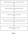
- FIG. 3 is a flowchart of a method for modifying presentation of audio content for a user based on a location of an audio system 200.
- the process shown in FIG. 3 may be performed by components of an audio system (e.g., audio system 200).
- Other entities may perform some or all of the steps in FIG. 3 in other examples. Examples may include different and/or additional steps, or perform the steps in different orders.
- An audio system 200 obtains 305 data describing a local area surrounding the audio system 200.
- the audio system 200 may be included in a headset 100 or in another type of wearable or portable device in various examples.
- the audio system 200 receives data from a position sensor 190.
- the position sensor 190 is included in the audio system 200 in some examples, while in other examples the position sensor 190 is included in a device that also includes the audio system 200.
- a headset 100 includes the position sensor 190 and the audio system 200.
- the position sensor generates one or more measurement signals in response to motion of the audio system 200 (or device including the audio system 200).
- the position sensor 190 enables simultaneous localization and mapping (SLAM) for a position of the audio system 200 and updating a model of the local area surrounding the audio system 200.
- SLAM simultaneous localization and mapping
- the audio controller 230 receives data from the position sensor 190, the acoustic sensor 180 to determine the location of the headset 100. In some examples, the audio controller may also use user interactions with the headset 100 to determine the location of the headset 100. In other examples, the audio controller may also receive image or video data from one or more imaging devices 130. The audio controller 230 may obtain images or videos of at least a portion of the local area from one or more imaging devices 130, such as red, green, blue (RGB) cameras. From the captured images and measurements from the position sensor, the audio controller 230 can determine parameters of the local area or determine a position (e.g., a location and a pose) of the audio system 200 in the local area.
- a position e.g., a location and a pose
- the audio system 200 obtains 305 information describing the local area from one or more other devices.
- a sensor array 220 captures audio from one or more sources in the local aera.
- the sensor array 220 includes one or more microphones that capture audio data from the local area, with the captured audio data comprising a characteristic of the local area. Capturing audio from the local area allows the audio system 200 to obtain additional information describing local area. For example, capturing audio allows the audio system 200 to identify characteristics of audio in the local area, such as frequencies of audio in the local area, amplitudes (or volumes) of audio in the local area.
- the sensor array 220 is separate from the audio system 200, with the audio system 200 receiving audio captured from the sensor array 220.
- one or more inputs that the audio system 200 receives from the user may be characteristics of the local area. For example, received inputs specifying a type of audio to present, a volume with which audio is presented, a duration with which audio is presented, or other inputs received by the audio system 200 that include information about presentation of audio are characteristics of the local area.
- data describing the local area includes a timestamp or other temporal information specifying a time when the data was obtained or was captured.
- the timestamp specifies a time when the audio system 200 obtained 305 the information, while in other examples, the timestamp specifies a time when the position sensor 190 or other device captured the information.
- the timestamp or temporal information specifies a date and a time when the position sensor 190 captured the data.
- the position sensor 190 includes a clock or other timing circuitry used to determine a timestamp or other timing information associated with the data describing the local area.
- an audio controller 230 of the audio system 200 includes the clock or timing circuity that generates a timestamp when the audio system 200 received data, allowing the time when data describing the local area was received to be another characteristic of the local area. Associating timestamps or other temporal information with data describing the local area allows data describing a local area to be correlated with a time to identify different information with different times.
- the audio system 200 determines 310 a location of the audio system 200.
- a "location" of the audio system 200 is a semantic location representing a physical location and additional context describing the physical location in various examples.
- the obtained information describing the local area provides context about the local area that allows the audio system 200 to determine a location corresponding to the local area, with the location of the local area identifying a type of the local area. For example, a combination of information describing a local area corresponds to a "gym" location, while a different combination of information describing the local area corresponds to a "vehicle” location. In another example, an additional combination of information describing a local area corresponds to a "residence" location.
- Information describing a location includes characteristics of audio captured from the local area, a time of day where the audio system 200 has been (or is likely to be) in the local area, image or video data corresponding to the type of local area, interactions by the user with the audio system 200, characteristics of audio content presented by the audio system 200, or other information describing characteristics of the local area (including user interactions). Different combinations of information may be associated with different locations (e.g., types of local areas). In some examples, a user of the audio system 200 specifies associations between a location and combinations of characteristics of a local area, allowing the user to personalize how different locations are defined.
- the audio system 200 determines associations between locations and combinations of characteristics of a local area. For example, an audio controller 230 of the audio system 200 applies one or more trained classification models to various combinations of data describing local areas, with a trained classification model outputting a location associated with a combination of characteristics of a local area. The audio controller 230 stores the location output by the classification model in association with the combination of characteristics that was input to the classification model.
- the audio system 200 trains the classification model by applying the classification model to labeled training examples.
- each training example includes a combination of characteristics of a local area, with a label applied to each training example identifying a location.
- the audio system 200 such as the audio controller 230, applies the classification model to each training example of a set.
- the audio system 200 compares an output of the classification model when applied to a training example to the label applied to the training example.
- the audio system 200 scores the output location from the classification model using a loss function that generates a score for the output of the classification model based on a comparison of the output location to the label applied to the training example.
- Example loss functions include the mean square error function, the mean absolute error, hinge loss function, and the cross entropy loss function.
- the audio system 200 applies gradient descent to update the set of parameters.
- the audio system 200 updates a set of parameters for the classification model using backpropagation based on the score generated by the loss function.
- the audio system 200 applies the classification model to training examples and updates parameters of the classification model until the loss function used by the audio system 200 to update the parameters of the classification model satisfies one or more conditions.
- the audio system 200 maintains a database associating locations with combinations of information describing a local area.
- FIG. 4 shows an example database 400 associating locations with combinations of information describing a local area.
- the database 400 includes different entries 405A, 405B (also referred to individually and collectively using reference number 400). Each entry 405 includes a location 410A, 410B (also referred to individually and collectively using reference number 410) and a combination of characteristics 415A, 415B (also referred to individually and collectively using reference number 415).
- Each entry 405 includes a location 410A, 410B (also referred to individually and collectively using reference number 410) and a combination of characteristics 415A, 415B (also referred to individually and collectively using reference number 415).
- FIG. 4 shows an example database 400 associating locations with combinations of information describing a local area.
- the database 400 includes different entries 405A, 405B (also referred to individually and collectively using reference number 400). Each entry 405 includes
- a local area having characteristics matching at least a threshold amount of the characteristics in combination of characteristics 415A corresponds to location 41 0A
- a local area having characteristics matching at least a threshold amount of the characteristics in combination of characteristics 415B corresponds to location 410B.
- a combination of characteristics 415 one or more of: a time range, characteristics of audio captured from a local area, inputs received by the audio system, images of the local area, video of the local area, of other data describing the local area in various examples.
- the database 400 is stored in association with a user, allowing different databases 400 to be maintained for different users, so different combinations of characteristics 415 may identify a location 410 for different users.
- the database 400 may be locally stored in a non-transitory computer-readable storage medium of the audio system 200 in various examples, while in other examples, the database 400 is stored in a different device that the audio system 200 accesses via a network or other connection.
- the database 400 is stored in a mapping server 725 and accessed by the audio system 200 through a network 720, as further described below in conjunction with FIG. 7 .
- the audio system 200 compares the obtained data to stored associations between locations and combinations of characteristics to determine 310 the location of the audio system 200. For example, the audio system 200 determines characteristics of the obtained information and compares the characteristics of the obtained information to stored combinations of characteristics associated with locations. The audio system 200 determines 310 the location of the audio system 200 as a location associated with a combination of characteristics matching a maximum amount (e.g., a maximum number, a maximum percentage) of characteristics of the obtained data describing the local area.
- a maximum amount e.g., a maximum number, a maximum percentage
- the audio system 200 determines measures of similarity between the obtained data and locations associated with stored combinations of characteristics.
- the audio system 200 determines 310 the location of the audio system 200 as a location having a maximum measure of similarity to the obtained data. For example, the audio system 200 generates an embedding for the obtained data and generates an embedding for each location based on the combination of characteristics associated with a location.
- An embedding is a multidimensional vector representing the obtained data or a combination of characteristics in a latent space.
- the audio system 200 applies a trained model to combinations of characteristics, with the output of the model comprising an embedding corresponding to a combination of characteristics.
- the audio system 200 stores an embedding in association with a location associated with a combination of characteristics in various examples.
- Example measures of similarity between an embedding corresponding to the obtained data and an embedding corresponding to a location include a cosine similarity or a dot product, although other measures of similarity may be used in various examples.
- the audio system 200 determines 315 a location profile for the determined location.
- the location profile includes one or more acoustic parameters associated with the location.
- the audio system 200 stores a location profile with each of one or more locations and retrieves the stored location profile associated with the determined location.
- FIG. 5 shows an example database 500 associating location profiles with locations.
- the database 500 shown in FIG. 5 includes entries 505A, 505B (also referred to individually and collectively using reference number 500) that each include a location 51 0A, 510B (also referred to individually and collectively using reference number 510) and a location profile 515A, 515B (also referred to individually and collectively using reference number 515).
- the audio system 200 stores a location identifier uniquely identifying each location, and an entry 505 of the database 500 includes a location identifier and a location profile 515.
- the location profile 515 associated with a location 510 includes one or more acoustic parameters describing presentation of audio content to a user.
- Example acoustic parameters include noise suppression parameters, beamforming parameters, types of audio to be presented, a volume for audio presentation, a room impulse response for spatializing audio, or other parameters specifying audio to be presented or user perception of presented audio.
- Acoustic parameters included in a location profile 515 may be received by the audio system 200 from a user and stored in association with the user.
- the user may provide inputs specifying the acoustic parameters for a location profile 515 through an interface provided by a device, such as a headset 100.
- the audio system 200 provides default values for various acoustic parameters to the user, and inputs received from the user adjust the default values.
- the database 500 is stored in association with an identifier of a user in various examples, allowing the audio system 200 to maintain databases 500 for different users, allowing different users to specify individualized location profiles 515 for locations 510. While FIGS.
- a single database is associated with a user and includes entries having a location, a combination of information describing the local area corresponding to the location, and a location profile for the location.
- a location profile 515 for a location 510 includes one or more preferences of the user for audio.
- a location profile 515 includes a volume for audio content, a type of audio content, or other user-specific modifications to audio content.
- the location profile 515 includes a head-related transfer function for a user as a preference of the user, allowing the location profile 515 to account for a specific user to whom audio is presented.
- the head-related transfer function for the user is stored in the data store 235 in association with the user and is retrieved along with a location profile 515 determined for the location determined for the local area surrounding the audio system 200.
- the audio system 200 determines 315 the location profile for the obtained information by identifying a stored location profile associated with a location matching the determined location.
- the location profile includes one or more acoustic parameters for audio content to be presented to a user while the audio system 200 is in the determined location, as further described above in conjunction with FIG. 5 . This allows audio presented to a user while the audio system 200 is in the determined location to be presented subject to the user's preferences specified by the acoustic parameters, enabling the audio system 200 to automatically modify how audio content is presented to the user based on the obtained data describing the local area surrounding the audio system 200.
- one or more acoustic parameters in a location profile describe noise cancellation applied by the audio system 200.
- an acoustic parameter specifies one or more frequencies of audio (e.g., a frequency range) that are suppressed or cancelled in audio presented by the audio system 200.
- an acoustic parameter specifies an amount by which audio having a specific frequency range is suppressed, allowing the acoustic parameter to specify an amount of attenuation for certain audio.
- different acoustic parameters specify different frequency ranges and with corresponding amounts of attenuation, allowing different frequencies to be attenuated by different amounts.
- the location profile includes preferences for the user for how audio is presented by the audio system 200 while in a location associated with the location profile.
- the location profile includes a head related transfer function for the user to account for physical properties of the user when audio is presented to the user.
- one or more acoustic parameters in a location profile identifies one or more frequency ranges to emphasize, so the audio system 200 increases an amplitude of audio frequencies within an identified frequency range.
- the audio system 200 decreases an amplitude of audio frequencies in ranges other than the identified frequency range.
- different amplitudes are associated with different frequency ranges, allowing different levels of emphasis to be applied to different frequency ranges.
- one or more acoustic parameters identify a source of audio or characteristics of a source of audio, causing the audio system 200 to emphasize audio from the identified source in the local area or from a source in the local area having the identified characteristics relative to audio from different sources in the local area while the audio system 200 is in the location.
- an audio parameter identifies one or more regions of the local area, and the audio system 200 emphasizes audio from an identified region of the local area relative to audio from other regions of the local area.
- Such audio parameters allow a user to customize how audio within the local area is perceived by the user, allowing the audio to appear to be presented within a location having audio transmission characteristics described by the location profile.
- Other example acoustic parameters included in a location profile include a frequency response, an amount of gain for one or more portions of the audio, a compression ratio for the audio, a time constant for the audio, or other values affecting presentation of audio to a user.
- one or more acoustic parameters specify characteristics of audio presented to the user while the audio system 200 is in the location.
- an acoustic parameter specifies a source of the audio presented to the user.
- an acoustic parameter specifies that audio presented to the user is audio from the local area captured by a sensor array 220 of the audio system 200.
- an acoustic parameter specifies that audio presented to the user is obtained from a storage device or other device coupled to the audio system 200.
- one or more additional acoustic parameters identify characteristics of audio to retrieve and to present to the user.
- Example characteristics of audio to retrieve include a genre of audio, a type of audio, an artist associated with the audio, a specific audio file or playlist, or other information capable of identifying specific audio for presentation.
- One or more acoustic parameters may specify a volume with which audio is presented to the user by the audio system 200, a playback speed of audio presented to the user, or other characteristics specifying how audio is presented by the audio system 200.
- the audio system 200 modifies 320 audio content for presentation by the audio system 200 based on the one or more acoustic parameters included in the determined location profile and presents 325 the modified audio to the user.
- the audio system 200 modifies 320 audio based on the acoustic parameters in the location profile and presents 325 the modified audio to the user through one or more transducers in a transducer array 210 included in the audio system 200.
- the audio controller 230 of the audio system 200 applies one or more noise cancellation processes to modify 320 audio by removing portions of the audio with characteristics specified by one or more acoustic parameters included in the location profile; the audio system 200 subsequently presents 325 audio without the removed portions to the user via the transducer array 210.
- the audio controller 230 of the audio system 200 processes one or more ATFs to selectively emphasize audio from audio sources within the local area while de-emphasizing other audio based on one or more acoustic parameters included in the location profile.
- the audio system 200 presents 325 the modified audio, such as via one or more transducers of the transducer array 210.
- the audio system 200 retrieves audio based on one or more audio parameters of the location profile and presents 325 the retrieved audio to a user, such as through the transducer array 210.
- the sensor array 220 of the audio system 200 captures audio from the local area, and the audio controller 230 modifies 320 the captured audio based on the one or more audio parameters of the location profile.
- the audio system 200 presents 325 the modified audio captured from the local area, such as via the transducer array 210, allowing the audio system 200 to modify audio captured from the local area based on the location parameter.
- the audio system 200 continuously obtains 305 data describing the local area surrounding the audio system 200 and determines 310 the location of the audio system 200. This allows the audio system 200 to dynamically determine 310 its location based on obtained data describing the local area surrounding it. In response to changes in the obtained data, the audio system 200 determines 310 a different location based on the changed data and determines 315 a different location profile corresponding to the different location. This allows the audio system 200 to automatically update how audio is modified by automatically updating the location profile in response to changes in data describing the local area surrounding the audio system 200. Such automatic adjustment of audio modification allows the audio system 200 to differently present audio to a user in different locations without the user manually selecting or providing acoustic parameters for audio presentation when a local area surrounding the audio system 200 changes.
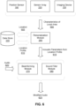
- FIG. 6 is a process flow diagram of a method for modifying presentation of audio content for a user based on a location of the user.
- an audio system 200 includes a personalization module 290 that receives characteristics 600 of a local area including the audio system 200.
- the characteristics 600 of the local area are obtained from one or more components or devices.
- Example components from which characteristics 600 of the local area are obtained include one or more of a position sensor 190 generating signals describing movement or position of the audio system 200, a sensor array 220 capturing audio from the local area, an imaging device 130 capturing video or images of the local area, one or more devices receiving input from a user, or other components.
- the characteristics 600 of the local area are received from different components or different combinations of components in various examples.
- the personalization module 290 of the audio system 200 determines a location 605 of the audio system 200. As further described above in conjunction with FIG. 3 , the personalization module 290 compares the obtained characteristics 600 of the local area to stored characteristics or combinations of characteristics associated with locations. In various examples, a data store 235 maintains associations between locations and combinations of characteristics, and the personalization module 290 selects the location 605 based on a comparison of the obtained characteristics 600 to stored combinations of characteristics associated with locations, as further described above in conjunction with FIG. 3 .
- each location profile 610 includes one or more acoustic parameters to be applied by the audio system 200 when presenting audio, allowing modification of the audio based on the acoustic parameters in the location profile 610.
- Example acoustic parameters included in a location profile include noise cancellation parameters, beamforming parameters, a frequency response, an amount of gain for audio, a compression ratio for the audio, a time constant for the audio.
- the location profile for a location includes one or more preferences specified by a user, allowing the location profile to account for both characteristics of a local area and user-specified data or preferences.
- the personalization module 290 provides acoustic parameters 615 from the location profile 610 to one or more of the beamforming module 270 and the sound filter module 280, which update one or more processes applied to audio based on the acoustic parameters 615. While FIG. 6 shows the personalization module 290 providing acoustic parameters 615 to the beamforming module 270 or to the sound filter module 280, in other examples, the acoustic parameters 615 are provided to different or additional components capable of modifying audio.
- the beamforming module 270 or the sound filter module 280 modify the audio 620 based on the acoustic parameters 615 from the location profile 610, and the modified audio 625 output by the beamforming module 270 or the sound filter module 280 (or by one or more other components) is presented to the user via a transducer array 210 or other device.
- the audio 620 is audio captured by the sensor array 220, so the acoustic parameters 615 from the location profile 610 are used to modify audio captured from the local area.
- the audio 620 is received from the data store 235 or from another source, and the audio system 200 modifies the audio 620 based on the acoustic parameters 615 from the location profile 610 before being presented to a user.
- FIG. 7 is a system 700 that includes a headset 705.
- the headset 705 may be the headset 100 of FIG. 1A or the headset 105 of FIG. 1B .
- the system 700 may operate in an artificial reality environment (e.g., a virtual reality environment, an augmented reality environment, a mixed reality environment, or some combination thereof).
- the system 700 shown by FIG. 7 includes the headset 705, an input/output (I/O) interface 710 that is coupled to a console 715, the network 720, and the mapping server 725. While FIG. 7 shows an example system 700 including one headset 705 and one I/O interface 710, in other examples any number of these components may be included in the system 700.
- each headset and I/O interface 710 communicating with the console 715.
- different and/or additional components may be included in the system 700.
- functionality described in conjunction with one or more of the components shown in FIG. 7 may be distributed among the components in a different manner than described in conjunction with FIG. 7 in some examples.
- some or all of the functionality of the console 715 may be provided by the headset 705.
- the headset 705 includes the display assembly 730, an optics block 735, one or more position sensors 740, and the DCA 745. Some examples of headset 705 have different components than those described in conjunction with FIG. 7 . Additionally, the functionality provided by various components described in conjunction with FIG. 7 may be differently distributed among the components of the headset 705 in other examples, or be captured in separate assemblies remote from the headset 705.
- the display assembly 730 displays content to the user in accordance with data received from the console 715.
- the display assembly 730 displays the content using one or more display elements (e.g., the display elements 120).
- a display element may be, e.g., an electronic display.
- the display assembly 730 comprises a single display element or multiple display elements (e.g., a display for each eye of a user).
- Examples of an electronic display include: a liquid crystal display (LCD), an organic light emitting diode (OLED) display, an active-matrix organic light-emitting diode display (AMOLED), a waveguide display, some other display, or some combination thereof.
- the display element 120 may also include some or all of the functionality of the optics block 735.
- the optics block 735 may magnify image light received from the electronic display, corrects optical errors associated with the image light, and presents the corrected image light to one or both eyeboxes of the headset 705.
- the optics block 735 includes one or more optical elements.
- Example optical elements included in the optics block 735 include: an aperture, a Fresnel lens, a convex lens, a concave lens, a filter, a reflecting surface, or any other suitable optical element that affects image light.
- the optics block 735 may include combinations of different optical elements.
- one or more of the optical elements in the optics block 735 may have one or more coatings, such as partially reflective or anti-reflective coatings.
- Magnification and focusing of the image light by the optics block 735 allows the electronic display to be physically smaller, weigh less, and consume less power than larger displays. Additionally, magnification may increase the field of view of the content presented by the electronic display. For example, the field of view of the displayed content is such that the displayed content is presented using almost all (e.g., approximately 110 degrees diagonal), and in some cases, all of the user's field of view. Additionally, in some examples, the amount of magnification may be adjusted by adding or removing optical elements.
- the optics block 735 may be designed to correct one or more types of optical error.
- optical error include barrel or pincushion distortion, longitudinal chromatic aberrations, or transverse chromatic aberrations.
- Other types of optical errors may further include spherical aberrations, chromatic aberrations, or errors due to the lens field curvature, astigmatisms, or any other type of optical error.
- content provided to the electronic display for display is pre-distorted, and the optics block 735 corrects the distortion when it receives image light from the electronic display generated based on the content.
- the position sensor 740 is an electronic device that generates data indicating a position of the headset 705.
- the position sensor 740 generates one or more measurement signals in response to motion of the headset 705.
- the position sensor 190 is an example of the position sensor 740.
- Examples of a position sensor 740 include: one or more IMUs, one or more accelerometers, one or more gyroscopes, one or more magnetometers, another suitable type of sensor that detects motion, or some combination thereof.
- the position sensor 740 may include multiple accelerometers to measure translational motion (forward/back, up/down, left/right) and multiple gyroscopes to measure rotational motion (e.g., pitch, yaw, roll).
- an IMU rapidly samples the measurement signals and calculates the estimated position of the headset 705 from the sampled data. For example, the IMU integrates the measurement signals received from the accelerometers over time to estimate a velocity vector and integrates the velocity vector over time to determine an estimated position of a reference point on the headset 705.
- the reference point is a point that may be used to describe the position of the headset 705. While the reference point may generally be defined as a point in space, however, in practice the reference point is defined as a point within the headset 705.
- the DCA 745 generates depth information for a portion of the local area.
- the DCA includes one or more imaging devices and a DCA controller.
- the DCA 745 may also include an illuminator. Operation and structure of the DCA 745 is described above with regard to FIG. 1A .
- the audio system 750 provides audio content to a user of the headset 705.
- the audio system 750 is substantially the same as the audio system 200 describe above.
- the audio system 750 may comprise one or acoustic sensors, one or more transducers, and an audio controller.
- the audio system 750 may provide spatialized audio content to the user.
- the audio system 750 may request acoustic parameters from the mapping server 725 over the network 720.
- the acoustic parameters describe one or more acoustic properties (e.g., room impulse response, a reverberation time, a reverberation level, etc.) of the local area.
- the audio system 750 may provide information describing at least a portion of the local area from e.g., the DCA 745 and/or location information for the headset 705 from the position sensor 740.
- the audio system 750 may generate one or more sound filters using one or more of the acoustic parameters received from the mapping server 725, and use the sound filters to provide audio content to the user.
- the I/O interface 710 is a device that allows a user to send action requests and receive responses from the console 715.
- An action request is a request to perform a particular action.
- an action request may be an instruction to start or end capture of image or video data, or an instruction to perform a particular action within an application.
- the I/O interface 710 may include one or more input devices.
- Example input devices include: a keyboard, a mouse, a game controller, or any other suitable device for receiving action requests and communicating the action requests to the console 715.
- An action request received by the I/O interface 710 is communicated to the console 715, which performs an action corresponding to the action request.
- the I/O interface 710 includes an IMU that captures calibration data indicating an estimated position of the I/O interface 710 relative to an initial position of the I/O interface 710.
- the I/O interface 710 may provide haptic feedback to the user in accordance with instructions received from the console 715. For example, haptic feedback is provided when an action request is received, or the console 715 communicates instructions to the I/O interface 710 causing the I/O interface 710 to generate haptic feedback when the console 715 performs an action.
- the console 715 provides content to the headset 705 for processing in accordance with information received from one or more of: the DCA 745, the headset 705, and the I/O interface 710.
- the console 715 includes an application store 755, a tracking module 760, and an engine 765.
- Some examples of the console 715 have different modules or components than those described in conjunction with FIG. 7 .
- the functions further described below may be distributed among components of the console 715 in a different manner than described in conjunction with FIG. 7 .
- the functionality discussed herein with respect to the console 715 may be implemented in the headset 705, or a remote system.
- the application store 755 stores one or more applications for execution by the console 715.
- An application is a group of instructions, that when executed by a processor, generates content for presentation to the user. Content generated by an application may be in response to inputs received from the user via movement of the headset 705 or the I/O interface 710. Examples of applications include: gaming applications, conferencing applications, video playback applications, or other suitable applications.
- the tracking module 760 tracks movements of the headset 705 or of the I/O interface 710 using information from the DCA 745, the one or more position sensors 740, or some combination thereof. For example, the tracking module 760 determines a position of a reference point of the headset 705 in a mapping of a local area based on information from the headset 705. The tracking module 760 may also determine positions of an object or virtual object. Additionally, in some examples, the tracking module 760 may use portions of data indicating a position of the headset 705 from the position sensor 740 as well as representations of the local area from the DCA 745 to predict a future location of the headset 705. The tracking module 760 provides the estimated or predicted future position of the headset 705 or the I/O interface 710 to the engine 765.
- the engine 765 executes applications and receives position information, acceleration information, velocity information, predicted future positions, or some combination thereof, of the headset 705 from the tracking module 760. Based on the received information, the engine 765 determines content to provide to the headset 705 for presentation to the user. For example, if the received information indicates that the user has looked to the left, the engine 765 generates content for the headset 705 that mirrors the user's movement in a virtual local area or in a local area augmenting the local area with additional content. Additionally, the engine 765 performs an action within an application executing on the console 715 in response to an action request received from the I/O interface 710 and provides feedback to the user that the action was performed. The provided feedback may be visual or audible feedback via the headset 705 or haptic feedback via the I/O interface 710.
- the network 720 couples the headset 705 and/or the console 715 to the mapping server 725.
- the network 720 may include any combination of local area and/or wide area networks using both wireless and/or wired communication systems.
- the network 720 may include the Internet, as well as mobile telephone networks.
- the network 720 uses standard communications technologies and/or protocols.
- the network 720 may include links using technologies such as Ethernet, 802.11, worldwide interoperability for microwave access (WiMAX), 2G/3G/4G mobile communications protocols, digital subscriber line (DSL), asynchronous transfer mode (ATM), InfiniBand, PCI Express Advanced Switching, etc.
- the networking protocols used on the network 720 can include multiprotocol label switching (MPLS), the transmission control protocol/Internet protocol (TCP/IP), the User Datagram Protocol (UDP), the hypertext transport protocol (HTTP), the simple mail transfer protocol (SMTP), the file transfer protocol (FTP), etc.
- MPLS multiprotocol label switching
- TCP/IP transmission control protocol/Internet protocol
- UDP User Datagram Protocol
- HTTP hypertext transport protocol
- HTTP simple mail transfer protocol
- FTP file transfer protocol
- the data exchanged over the network 720 can be represented using technologies and/or formats including image data in binary form (e.g. Portable Network Graphics (PNG)), hypertext markup language (HTML), extensible markup language (XML), etc.
- all or some of links can be encrypted using conventional encryption technologies such as secure sockets layer (SSL), transport layer security (TLS), virtual private networks (VPNs), Internet Protocol security (IPsec), etc.
- SSL secure sockets layer
- TLS transport layer security
- VPNs virtual private networks
- the mapping server 725 may include a database that stores a virtual model describing a plurality of spaces, wherein one location in the virtual model corresponds to a current configuration of a local area of the headset 705.
- the mapping server 725 receives, from the headset 705 via the network 720, information describing at least a portion of the local area and/or location information for the local area.
- the user may adjust privacy settings to allow or prevent the headset 705 from transmitting information to the mapping server 725.
- the mapping server 725 determines, based on the received information and/or location information, a location in the virtual model that is associated with the local area of the headset 705.
- the mapping server 725 determines (e.g., retrieves) one or more acoustic parameters associated with the local area, based in part on the determined location in the virtual model and any acoustic parameters associated with the determined location.
- the mapping server 725 may transmit the location of the local area and any values of acoustic parameters associated with the local area to the headset 705.
- One or more components of system 700 may contain a privacy module that stores one or more privacy settings for user data elements.
- the user data elements describe the user or the headset 705.
- the user data elements may describe a physical characteristic of the user, an action performed by the user, a location of the user of the headset 705, a location of the headset 705, an HRTF for the user, etc.
- Privacy settings (or "access settings") for a user data element may be stored in any suitable manner, such as, for example, in association with the user data element, in an index on an authorization server, in another suitable manner, or any suitable combination thereof.
- a privacy setting for a user data element specifies how the user data element (or particular information associated with the user data element) can be accessed, stored, or otherwise used (e.g., viewed, shared, modified, copied, executed, surfaced, or identified).
- the privacy settings for a user data element may specify a "blocked list" of entities that may not access certain information associated with the user data element.
- the privacy settings associated with the user data element may specify any suitable granularity of permitted access or denial of access. For example, some entities may have permission to see that a specific user data element exists, some entities may have permission to view the content of the specific user data element, and some entities may have permission to modify the specific user data element.
- the privacy settings may allow the user to allow other entities to access or store user data elements for a finite period of time.
- the privacy settings may allow a user to specify one or more geographic locations from which user data elements can be accessed. Access or denial of access to the user data elements may depend on the geographic location of an entity who is attempting to access the user data elements. For example, the user may allow access to a user data element and specify that the user data element is accessible to an entity only while the user is in a particular location. If the user leaves the particular location, the user data element may no longer be accessible to the entity. As another example, the user may specify that a user data element is accessible only to entities within a threshold distance from the user, such as another user of a headset within the same local area as the user. If the user subsequently changes location, the entity with access to the user data element may lose access, while a new group of entities may gain access as they come within the threshold distance of the user.
- the system 700 may include one or more authorization/privacy servers for enforcing privacy settings.
- a request from an entity for a particular user data element may identify the entity associated with the request and the user data element may be sent only to the entity if the authorization server determines that the entity is authorized to access the user data element based on the privacy settings associated with the user data element. If the requesting entity is not authorized to access the user data element, the authorization server may prevent the requested user data element from being retrieved or may prevent the requested user data element from being sent to the entity.
- a software module is implemented with a computer program product comprising a computer-readable medium containing computer program code, which can be executed by a computer processor for performing any or all the steps, operations, or processes described.
- Embodiments may also relate to an apparatus for performing the operations herein.
- This apparatus may be specially constructed for the required purposes, and/or it may comprise a general-purpose computing device selectively activated or reconfigured by a computer program stored in the computer.
- a computer program may be stored in a non-transitory, tangible computer readable storage medium, or any type of media suitable for storing electronic instructions, which may be coupled to a computer system bus.
- any computing systems referred to in the specification may include a single processor or may be architectures employing multiple processor designs for increased computing capability.
- Embodiments may also relate to a product that is produced by a computing process described herein.
- a product may comprise information resulting from a computing process, where the information is stored on a non-transitory, tangible computer readable storage medium and may include any embodiment of a computer program product or other data combination described herein.
Landscapes
- Engineering & Computer Science (AREA)
- Acoustics & Sound (AREA)
- Signal Processing (AREA)
- Physics & Mathematics (AREA)
- Health & Medical Sciences (AREA)
- Otolaryngology (AREA)
- General Health & Medical Sciences (AREA)
- Quality & Reliability (AREA)
- Human Computer Interaction (AREA)
- Multimedia (AREA)
- Audiology, Speech & Language Pathology (AREA)
- Computational Linguistics (AREA)
- Stereophonic System (AREA)
- Circuit For Audible Band Transducer (AREA)
Abstract
Description
- This disclosure relates generally to artificial reality systems, and more specifically to updating audio presented by an artificial reality system based on a location of the artificial reality system.
- Wearable devices, such as artificial reality headsets, present audio to a user. For example, a wearable device includes one or more speakers or is coupled to one or more speakers, with the one or more speakers presenting audio to a user. As the location of the wearable device changes, acoustic properties of the location including the audio system also change. Such changes in acoustic properties between locations affect how audio presented from the wearable device is perceived by a user.
- Additionally, users have different preferences for audio when the audio is presented in different locations. The user's preferences may mitigate or accentuate acoustic properties of the local area surrounding the user. For example, a user provides various inputs to a wearable device to specify one or more audio parameters for presentation of audio when the user enters a location. However, when the user moves to a different location, the user provides additional inputs to the wearable device tailor one or more audio parameters for the different location, which changes how the wearable device presents audio while in the different location. Such manual configuration of audio parameters for different locations increases an amount of user interaction with the wearable device, increasing complexity of customizing audio presentation to account for different properties of different locations.
- Users have different preferences for audio presented by a wearable device, such as a headset, in different locations. For example, a user modifies one or more acoustic parameters of an audio system of the wearable device to modify how the wearable device presents audio. In various embodiments, the user provides multiple inputs to the wearable device through one or more user interfaces to modify the acoustic parameters. However, when the user moves to a different location, the user again provides additional inputs to the wearable device to alter one or more audio parameters so audio presentation accounts for the different location. The present disclosure aims to simplify modification of audio presentation for a user in different locations.
- According to a first aspect, there is provided a method comprising: obtaining data describing a local area surrounding an audio system from a position sensor; determining a location of the audio system from the obtained data; determining a location profile of the location, the location profile including one or more acoustic parameters associated with the location; modifying audio content for presentation by one or more transducers of the audio system based on the one or more acoustic parameters included in the location profile; and presenting the modified audio content to a user via a transducer array included in the audio system.
- Determining the location profile of the location may comprise: obtaining one or more preferences stored by the user for presentation of audio content; and determining the location profile of the location based on the determined location and the one or more preferences stored by the user.
- The one or more preferences stored by the user may include a head related transfer function stored in association with the user.
- The data describing the local area surrounding the audio system may include a time when the audio system is surrounded by the local area.
- The data describing the local area surrounding the audio system may include information describing audio from the local area captured by a sensor array of the audio system.
- The data describing the local area surrounding the audio system may identify audio presented by the transducer array.
- Modifying audio content for presentation by the one or more transducers of the audio system based on the one or more acoustic parameters associated with the location profile may comprise enhancing audio from one or more sound sources captured by a sensor array of the audio system relative to audio from other sound sources captured by the sensor array.
- Modifying audio content for presentation by one or more transducers of the audio system based on the one or more acoustic parameters associated with the location profile may comprise removing audio having one or more characteristics specified by the one or more acoustic parameters.
- The obtained data describing the local area may include audio captured by a sensor array of the audio system.
- The audio content for presentation by one or more transducers of the audio system may comprise audio captured from the local area by one or more sensors of the audio system.
- According to a second aspect, there is provided a headset comprising: a frame; one or more display elements coupled to the frame, each display element configured to generate image light; a position sensor configured to generate data indicating a position of the headset in a local area; and an audio system including a transducer array configured to present audio, a sensor array configured to capture audio from a local area including the headset, and an audio controller, the audio controller including a processor and a computer readable storage medium having stored instructions that, when executed by the processor, cause the audio system to carry out the method of the first aspect. The storage medium may be non-transitory.
- According to a third aspect, there is provided a computer program product comprising instructions that, when executed by a processor, causes the processor to carry out the method of the first aspect.
- According to a fourth aspect, there is provided a computer readable storage medium having stored instructions that, when executed by a processor, causes the processor to carry out the method of the first aspect. The storage medium may be non-transitory.
-
-
FIG. 1A is a perspective view of a headset implemented as an eyewear device. -
FIG. 1B is a perspective view of a headset implemented as a head-mounted display. -
FIG. 2 is a block diagram of an audio system. -
FIG. 3 is a flowchart illustrating a method for modifying presentation of audio content for a user based on a location of an audio system. -
FIG. 4 is an example database associating locations with combinations of information describing a local area. -
FIG. 5 is an example database associating locations with location profiles including acoustic parameters. -
FIG. 6 is a process flow diagram of a method for modifying presentation of audio content for a user based on a location of an audio system. -
FIG. 7 is a system that includes a headset. - The figures depict various examples for purposes of illustration only. One skilled in the art will readily recognize from the following discussion that alternative examples of the structures and methods illustrated herein may be employed without departing from the principles described herein.
- Users have different preferences for audio presentation by a wearable device, such as a headset or a pair of audio glasses, in different locations. For example, a user provides various inputs to a wearable device to change one or more acoustic parameters to modify presentation of audio while the wearable device is in a first location. However, when the wearable device moves to a different location, the user provides additional inputs to the wearable device to alter one or more audio parameters to adjust audio presentation while the wearable device is in the different location. While this allows audio presented by the wearable device to be tailored for different locations based on inputs received from the user, manual configuration of location-specific audio parameters increases an amount of user interaction with the wearable device, resulting in a corresponding complexity for the user to customize how audio is presented when the wearable device is in different locations and to update presentation of audio as the wearable device's location changes.
- To simplify modification of audio presentation based on a location of a wearable device, such as a headset or a pair of audio glasses, the wearable device obtains data describing characteristics of the local area surrounding the wearable device. Characteristics of the local area include images of the local area, audio captured from the local area, movement or positioning of the wearable device in the local area, interactions with the wearable device while the user is in the local area, or other information. The characteristics of the local area may be obtained from one or more components of the wearable device or from one or more components coupled to the wearable device. From the obtained characteristics of the local area, the wearable device determines a location of the wearable device. In various embodiments, the location is a semantic location identifying a physical location as well as context surrounding the physical location. For example, locations identify a "gym," a "home," and "office," or a "car," allowing a location to specify a type of local area including the wearable device. Based on the determined location, the wearable device retrieves a location profile corresponding to the determined location. The location profile includes one or more acoustic parameters specifying now the wearable device modifies audio for presentation to the user, so the wearable device presents audio subject to the acoustic parameters from the location profile. This allows the wearable device to automatically determine acoustic parameters for a local area surrounding the wearable device based on characteristics of the local area, which enables the wearable device to automatically update how audio is presented to a user based on characteristics from the local area surrounding the wearable device.
- Embodiments of the invention may include or be implemented in conjunction with an artificial reality system. Artificial reality is a form of reality that has been adjusted in some manner before presentation to a user, which may include, e.g., a virtual reality (VR), an augmented reality (AR), a mixed reality (MR), a hybrid reality, or some combination and/or derivatives thereof. Artificial reality content may include completely generated content or generated content combined with captured (e.g., real-world) content. The artificial reality content may include video, audio, haptic feedback, or some combination thereof, any of which may be presented in a single channel or in multiple channels (such as stereo video that produces a three-dimensional effect to the viewer). Additionally, in some embodiments, artificial reality may also be associated with applications, products, accessories, services, or some combination thereof, that are used to create content in an artificial reality and/or are otherwise used in an artificial reality. The artificial reality system that provides the artificial reality content may be implemented on various platforms, including a wearable device (e.g., headset, audio glasses) connected to a host computer system, a standalone wearable device (e.g., headset, audio glasses), a mobile device or computing system, or any other hardware platform capable of providing artificial reality content to one or more viewers.
-
FIG. 1A is a perspective view of aheadset 100 implemented as an eyewear device. In some examples, the eyewear device is a near eye display (NED). In general, theheadset 100 may be worn on the face of a user such that content (e.g., media content) is presented using a display assembly and/or an audio system. However, theheadset 100 may also be used such that media content is presented to a user in a different manner. Examples of media content presented by theheadset 100 include one or more images, video, audio, or some combination thereof. Theheadset 100 includes a frame, and may include, among other components, a display assembly including one ormore display elements 120, a depth camera assembly (DCA), an audio system, and aposition sensor 190. WhileFIG. 1A illustrates the components of theheadset 100 in example locations on theheadset 100, the components may be located elsewhere on theheadset 100, on a peripheral device paired with theheadset 100, or some combination thereof. Similarly, there may be more or fewer components on theheadset 100 than what is shown inFIG. 1A . - The
frame 110 holds the other components of theheadset 100. Theframe 110 includes a front part that holds the one ormore display elements 120 and end pieces (e.g., temples) to attach to a head of the user. The front part of theframe 110 bridges the top of a nose of the user. The length of the end pieces may be adjustable (e.g., adjustable temple length) to fit different users. The end pieces may also include a portion that curls behind the ear of the user (e.g., temple tip, ear piece). - The one or
more display elements 120 provide light to a user wearing theheadset 100. As illustrated the headset includes adisplay element 120 for each eye of a user. In some examples, adisplay element 120 generates image light that is provided to an eyebox of theheadset 100. The eyebox is a location in space that an eye of user occupies while wearing theheadset 100. For example, adisplay element 120 may be a waveguide display. A waveguide display includes a light source (e.g., a two-dimensional source, one or more line sources, one or more point sources, etc.) and one or more waveguides. Light from the light source is in-coupled into the one or more waveguides which outputs the light in a manner such that there is pupil replication in an eyebox of theheadset 100. In-coupling and/or outcoupling of light from the one or more waveguides may be done using one or more diffraction gratings. In some examples, the waveguide display includes a scanning element (e.g., waveguide, mirror, etc.) that scans light from the light source as it is in-coupled into the one or more waveguides. Note that in some examples, one or both of thedisplay elements 120 are opaque and do not transmit light from a local area around theheadset 100. The local area is the area surrounding theheadset 100. For example, the local area may be a room that a user wearing theheadset 100 is inside, or the user wearing theheadset 100 may be outside and the local area is an outside area. In this context, theheadset 100 generates VR content. Alternatively, in some examples, one or both of thedisplay elements 120 are at least partially transparent, such that light from the local area may be combined with light from the one or more display elements to produce AR and/or MR content. - In some examples, a
display element 120 does not generate image light, and instead is a lens that transmits light from the local area to the eyebox. For example, one or both of thedisplay elements 120 may be a lens without correction (non-prescription) or a prescription lens (e.g., single vision, bifocal and trifocal, or progressive) to help correct for defects in a user's eyesight. In some examples, thedisplay element 120 may be polarized and/or tinted to protect the user's eyes from the sun. - In some examples, the
display element 120 may include an additional optics block (not shown). The optics block may include one or more optical elements (e.g., lens, Fresnel lens, etc.) that direct light from thedisplay element 120 to the eyebox. The optics block may, e.g., correct for aberrations in some or all of the image content, magnify some or all of the image, or some combination thereof. - The DCA determines depth information for a portion of a local area surrounding the
headset 100. The DCA includes one ormore imaging devices 130 and a DCA controller (not shown inFIG. 1A ), and may also include anilluminator 140. In some examples, theilluminator 140 illuminates a portion of the local area with light. The light may be, e.g., structured light (e.g., dot pattern, bars, etc.) in the infrared (IR), IR flash for time-of-flight, etc. In some examples, the one ormore imaging devices 130 capture images of the portion of the local area that include the light from theilluminator 140. As illustrated,FIG. 1A shows asingle illuminator 140 and twoimaging devices 130. In alternate examples, there is noilluminator 140 and at least twoimaging devices 130. - The DCA controller computes depth information for the portion of the local area using the captured images and one or more depth determination techniques. The depth determination technique may be, e.g., direct time-of-flight (ToF) depth sensing, indirect ToF depth sensing, structured light, passive stereo analysis, active stereo analysis (uses texture added to the scene by light from the illuminator 140), some other technique to determine depth of a scene, or some combination thereof.
- The audio system provides audio content. The audio system includes a transducer array, a sensor array, and an
audio controller 150. However, in other examples, the audio system may include different and/or additional components. Similarly, in some cases, functionality described with reference to the components of the audio system can be distributed among the components in a different manner than is described here. For example, some or all of the functions of the controller may be performed by a remote server. - The transducer array presents sound to user. The transducer array includes a plurality of transducers. A transducer may be a
speaker 160 or a tissue transducer 170 (e.g., a bone conduction transducer or a cartilage conduction transducer). Although thespeakers 160 are shown exterior to theframe 110, thespeakers 160 may be enclosed in theframe 110. In some examples, instead of individual speakers for each ear, theheadset 100 includes a speaker array comprising multiple speakers integrated into theframe 110 to improve directionality of presented audio content. Thetissue transducer 170 couples to the head of the user and directly vibrates tissue (e.g., bone or cartilage) of the user to generate sound. The number and/or locations of transducers may be different from what is shown inFIG. 1A . - The sensor array detects sounds within the local area of the
headset 100. The sensor array includes a plurality ofacoustic sensors 180. Anacoustic sensor 180 captures sounds emitted from one or more sound sources in the local area (e.g., a room). Each acoustic sensor is configured to detect sound and convert the detected sound into an electronic format (analog or digital). Theacoustic sensors 180 may be acoustic wave sensors, microphones, sound transducers, or similar sensors that are suitable for detecting sounds. - In some examples, one or more
acoustic sensors 180 may be placed in an ear canal of each ear (e.g., acting as binaural microphones). In some examples, theacoustic sensors 180 may be placed on an exterior surface of theheadset 100, placed on an interior surface of theheadset 100, separate from the headset 100 (e.g., part of some other device), or some combination thereof. The number and/or locations ofacoustic sensors 180 may be different from what is shown inFIG. 1A . For example, the number of acoustic detection locations may be increased to increase the amount of audio information collected and the sensitivity and/or accuracy of the information. The acoustic detection locations may be oriented such that the microphone is able to detect sounds in a wide range of directions surrounding the user wearing theheadset 100. - The
audio controller 150 processes information from the sensor array that describes sounds detected by the sensor array. Theaudio controller 150 may comprise a processor and a computer-readable storage medium. Theaudio controller 150 may be configured to generate direction of arrival (DOA) estimates, generate acoustic transfer functions (e.g., array transfer functions and/or head-related transfer functions), track the location of sound sources, form beams in the direction of sound sources, classify sound sources, generate sound filters for thespeakers 160, or some combination thereof. As further described below in conjunction withFIGS. 3-6 , theaudio controller 150 obtains characteristics of a local area surrounding theheadset 100 from theposition sensor 190 and theacoustic sensor 180. In some examples, the audio controller may also use user interactions with theheadset 100 to determine the location of theheadset 100. In other examples, the audio controller may also receive image or video data from one ormore imaging devices 130. Based on the obtained characteristics, theaudio controller 150 determines a location of theheadset 100 and retrieves a location profile for the determined location. The location profile includes one or more acoustic parameters specifying modification of audio by theaudio controller 150 prior to presentation of the audio to the user. This allows theaudio controller 150 to dynamically determine how to modify audio based on characteristics of the local area surrounding theheadset 100. - The
position sensor 190 generates one or more measurement signals in response to motion of theheadset 100. Theposition sensor 190 may be located on a portion of theframe 110 of theheadset 100. Theposition sensor 190 may include an inertial measurement unit (IMU). Examples ofposition sensor 190 include: one or more accelerometers, one or more gyroscopes, one or more magnetometers, another suitable type of sensor that detects motion, a type of sensor used for error correction of the IMU, or some combination thereof. Theposition sensor 190 may be located external to the IMU, internal to the IMU, or some combination thereof. - In some examples, the
headset 100 may provide for simultaneous localization and mapping (SLAM) for a position of theheadset 100 and updating of a model of the local area. For example, theheadset 100 may include a passive camera assembly (PCA) that generates color image data. The PCA may include one or more RGB cameras that capture images of some or all of the local area. In some examples, some or all of theimaging devices 130 of the DCA may also function as the PCA. The images captured by the PCA and the depth information determined by the DCA may be used to determine parameters of the local area, generate a model of the local area, update a model of the local area, or some combination thereof. Furthermore, theposition sensor 190 tracks the position (e.g., location and pose) of theheadset 100 within the room. Additional details regarding the components of theheadset 100 are discussed below in connection withFIG 7 . -
FIG. 1B is a perspective view of aheadset 105 implemented as a HMD. In examples that describe an AR system and/or a MR system, portions of a front side of the HMD are at least partially transparent in the visible band (~380 nm to 750 nm), and portions of the HMD that are between the front side of the HMD and an eye of the user are at least partially transparent (e.g., a partially transparent electronic display). The HMD includes a frontrigid body 115 and aband 175. Theheadset 105 includes many of the same components described above with reference toFIG. 1A , but modified to integrate with the HMD form factor. For example, the HMD includes a display assembly, a DCA, an audio system, and aposition sensor 190.FIG. 1B shows theilluminator 140, a plurality of thespeakers 160, a plurality of theimaging devices 130, a plurality ofacoustic sensors 180, and theposition sensor 190. Thespeakers 160 may be located in various locations, such as coupled to the band 175 (as shown), coupled to frontrigid body 115, or may be configured to be inserted within the ear canal of a user. -
FIG. 2 is a block diagram of anaudio system 200. The audio system inFIG. 1A orFIG. 1B may be an example of theaudio system 200. Theaudio system 200 generates one or more acoustic transfer functions for a user. Theaudio system 200 may then use the one or more acoustic transfer functions to generate audio content for the user. In the example ofFIG. 2 , theaudio system 200 includes atransducer array 210, asensor array 220, and anaudio controller 230. Some examples of theaudio system 200 have different components than those described here. Similarly, in some cases, functions can be distributed among the components in a different manner than is described here. - The
transducer array 210 is configured to present audio content. Thetransducer array 210 includes a plurality of transducers. A transducer is a device that provides audio content. A transducer may be, e.g., a speaker (e.g., the speaker 160), a tissue transducer (e.g., the tissue transducer 170), some other device that provides audio content, or some combination thereof. A tissue transducer may be configured to function as a bone conduction transducer or a cartilage conduction transducer. Thetransducer array 210 may present audio content via air conduction (e.g., via one or more speakers), via bone conduction (via one or more bone conduction transducer), via cartilage conduction audio system (via one or more cartilage conduction transducers), or some combination thereof. In some examples, thetransducer array 210 may include one or more transducers to cover different parts of a frequency range. For example, a piezoelectric transducer may be used to cover a first part of a frequency range and a moving coil transducer may be used to cover a second part of a frequency range. - The bone conduction transducers generate acoustic pressure waves by vibrating bone/tissue in the user's head. A bone conduction transducer may be coupled to a portion of a headset, and may be configured to be behind the auricle coupled to a portion of the user's skull. The bone conduction transducer receives vibration instructions from the
audio controller 230, and vibrates a portion of the user's skull based on the received instructions. The vibrations from the bone conduction transducer generate a tissue-borne acoustic pressure wave that propagates toward the user's cochlea, bypassing the eardrum. - The cartilage conduction transducers generate acoustic pressure waves by vibrating one or more portions of the auricular cartilage of the ears of the user. A cartilage conduction transducer may be coupled to a portion of a headset, and may be configured to be coupled to one or more portions of the auricular cartilage of the ear. For example, the cartilage conduction transducer may couple to the back of an auricle of the ear of the user. The cartilage conduction transducer may be located anywhere along the auricular cartilage around the outer ear (e.g., the pinna, the tragus, some other portion of the auricular cartilage, or some combination thereof). Vibrating the one or more portions of auricular cartilage may generate: airborne acoustic pressure waves outside the ear canal; tissue born acoustic pressure waves that cause some portions of the ear canal to vibrate thereby generating an airborne acoustic pressure wave within the ear canal; or some combination thereof. The generated airborne acoustic pressure waves propagate down the ear canal toward the ear drum.
- The
transducer array 210 generates audio content in accordance with instructions from theaudio controller 230. In some examples, the audio content is spatialized. Spatialized audio content is audio content that appears to originate from a particular direction and/or target region (e.g., an object in the local area and/or a virtual object). For example, spatialized audio content can make it appear that sound is originating from a virtual singer across a room from a user of theaudio system 200. Thetransducer array 210 may be coupled to a wearable device (e.g., theheadset 100 or the headset 105). In alternate examples, thetransducer array 210 may be a plurality of speakers that are separate from the wearable device (e.g., coupled to an external console). - The
sensor array 220 detects sounds within a local area surrounding thesensor array 220. Thesensor array 220 may include a plurality of acoustic sensors that each detect air pressure variations of a sound wave and convert the detected sounds into an electronic format (analog or digital). The plurality of acoustic sensors may be positioned on a headset (e.g.,headset 100 and/or the headset 105), on a user (e.g., in an ear canal of the user), on a neckband, or some combination thereof. An acoustic sensor may be, e.g., a microphone, a vibration sensor, an accelerometer, or any combination thereof. In some examples, thesensor array 220 is configured to monitor the audio content generated by thetransducer array 210 using at least some of the plurality of acoustic sensors. Increasing the number of sensors may improve the accuracy of information (e.g., directionality) describing a sound field produced by thetransducer array 210 and/or sound from the local area. - The
audio controller 230 controls operation of theaudio system 200. In the example ofFIG. 2 , theaudio controller 230 includes adata store 235, aDOA estimation module 240, atransfer function module 250, atracking module 260, abeamforming module 270, and asound filter module 280. Theaudio controller 230 may be located inside a headset, in some examples. Some examples of theaudio controller 230 have different components than those described here. Similarly, functions can be distributed among the components in different manners than described here. For example, some functions of the controller may be performed external to the headset. The user may opt in to allow theaudio controller 230 to transmit data captured by the headset to systems external to the headset, and the user may select privacy settings controlling access to any such data. - The
data store 235 stores data for use by theaudio system 200. Data in thedata store 235 may include sounds recorded in the local area of theaudio system 200, audio content, head-related transfer functions (HRTFs), transfer functions for one or more sensors, array transfer functions (ATFs) for one or more of the acoustic sensors, sound source locations, virtual model of local area, direction of arrival estimates, sound filters, and other data relevant for use by theaudio system 200, or any combination thereof. - The user may opt-in to allow the
data store 235 to record data captured by theaudio system 200. In some examples, theaudio system 200 may employ always on recording, in which theaudio system 200 records all sounds captured by theaudio system 200 in order to improve the experience for the user. The user may opt in or opt out to allow or prevent theaudio system 200 from recording, storing, or transmitting the recorded data to other entities. - In various examples, the
data store 235 includes associations between combinations of characteristics and locations. As further described below in conjunction withFIG. 3 , a location is a semantic location representing a physical location and additional context describing the physical location. For example, a location is "home" and is associated with combinations of characteristics of data obtained by theaudio system 200. As another example, a location is "gym" and is associated with another combination of characteristics of data obtained by theaudio system 200. Hence, a location describes a local area surrounding theaudio system 200. As further described below in conjunction withFIG. 3 , characteristics of data include one or more signals from aposition sensor 190 describing movement of theaudio system 200, user interactions with theaudio system 200, a time (e.g., a day and a time of day) when characteristics were obtained, audio captured from a local area from thesensor array 220, audio presented by thetransducer array 210, images from animaging device 130, or other information describing a local area surrounding theaudio system 200 or interactions with theaudio system 200. In some examples, thedata store 235 maintains a database including entries that each include a location and a corresponding combination of characteristics, as further described below in conjunction withFIG. 4 . The database is associated with a user in some examples, allowing thedata store 235 to include different databases identifying locations and combinations of characteristics for different users. - Additionally, the
data store 235 stores associations between locations and location profiles, where a location profile associated with a location includes one or more acoustic parameters. The acoustic parameters in a location profile identify one or more modifications to audio by theaudio system 200 when presenting audio to a user while theaudio system 200 is in a location associated with the location profile. Example acoustic parameters included in a location profile include noise cancellation parameters, beamforming parameters, a frequency response, an amount of gain for audio, a compression ratio for the audio, a time constant for the audio. In some examples, thedata store 235 includes a database including entries that each have a location and a corresponding location profile, such as the example further described below in conjunction withFIG. 5 . The database may be associated with a user, allowing the database to include user-specific location profiles. Alternatively, thedata store 235 includes a single database, where an entry in the database includes a location, a combination of characteristics corresponding to the location, and a location profile associated with the location. The database may be associated with a user in various examples, allowing thedata store 235 to include different databases with different relationships between locations, combinations of characteristics identifying locations, and location profiles for different users. - The
DOA estimation module 240 is configured to localize sound sources in the local area based in part on information from thesensor array 220. Localization is a process of determining where sound sources are located relative to the user of theaudio system 200. TheDOA estimation module 240 performs a DOA analysis to localize one or more sound sources within the local area. The DOA analysis may include analyzing the intensity, spectra, and/or arrival time of each sound at thesensor array 220 to determine the direction from which the sounds originated. In some cases, the DOA analysis may include any suitable algorithm for analyzing a surrounding acoustic environment in which theaudio system 200 is located. - For example, the DOA analysis may be designed to receive input signals from the
sensor array 220 and apply digital signal processing algorithms to the input signals to estimate a direction of arrival. These algorithms may include, for example, delay and sum algorithms where the input signal is sampled, and the resulting weighted and delayed versions of the sampled signal are averaged together to determine a DOA. A least mean squared (LMS) algorithm may also be implemented to create an adaptive filter. This adaptive filter may then be used to identify differences in signal intensity, for example, or differences in time of arrival. These differences may then be used to estimate the DOA. In another example, the DOA may be determined by converting the input signals into the frequency domain and selecting specific bins within the time-frequency (TF) domain to process. Each selected TF bin may be processed to determine whether that bin includes a portion of the audio spectrum with a direct path audio signal. Those bins having a portion of the direct-path signal may then be analyzed to identify the angle at which thesensor array 220 received the direct-path audio signal. The determined angle may then be used to identify the DOA for the received input signal. Other algorithms not listed above may also be used alone or in combination with the above algorithms to determine DOA. - In some examples, the
DOA estimation module 240 may also determine the DOA with respect to an absolute position of theaudio system 200 within the local area. The position of thesensor array 220 may be received from an external system (e.g., some other component of a headset, an artificial reality console, a mapping server, a position sensor (e.g., the position sensor 190), etc.). The external system may create a virtual model of the local area, in which the local area and the position of theaudio system 200 are mapped. The received position information may include a location and/or an orientation of some or all of the audio system 200 (e.g., of the sensor array 220). TheDOA estimation module 240 may update the estimated DOA based on the received position information. - The
transfer function module 250 is configured to generate one or more acoustic transfer functions. Generally, a transfer function is a mathematical function giving a corresponding output value for each possible input value. Based on parameters of the detected sounds, thetransfer function module 250 generates one or more acoustic transfer functions associated with the audio system. The acoustic transfer functions may be array transfer functions (ATFs), head-related transfer functions (HRTFs), other types of acoustic transfer functions, or some combination thereof. An ATF characterizes how the microphone receives a sound from a point in space. - An ATF includes a number of transfer functions that characterize a relationship between the sound source and the corresponding sound received by the acoustic sensors in the
sensor array 220. Accordingly, for a sound source there is a corresponding transfer function for each of the acoustic sensors in thesensor array 220. And collectively the set of transfer functions is referred to as an ATF. Accordingly, for each sound source there is a corresponding ATF. Note that the sound source may be, e.g., someone or something generating sound in the local area, the user, or one or more transducers of thetransducer array 210. The ATF for a particular sound source location relative to thesensor array 220 may differ from user to user due to a person's anatomy (e.g., ear shape, shoulders, etc.) that affects the sound as it travels to the person's ears. Accordingly, the ATFs of thesensor array 220 are personalized for each user of theaudio system 200. - In some examples, the
transfer function module 250 determines one or more HRTFs for a user of theaudio system 200. The HRTF characterizes how an ear receives a sound from a point in space. The HRTF for a particular source location relative to a person is unique to each ear of the person (and is unique to the person) due to the person's anatomy (e.g., ear shape, shoulders, etc.) that affects the sound as it travels to the person's ears. In some examples, thetransfer function module 250 may determine HRTFs for the user using a calibration process. In some examples, thetransfer function module 250 may provide information about the user to a remote system. The user may adjust privacy settings to allow or prevent thetransfer function module 250 from providing the information about the user to any remote systems. The remote system determines a set of HRTFs that are customized to the user using, e.g., machine learning, and provides the customized set of HRTFs to theaudio system 200. - The
tracking module 260 is configured to track locations of one or more sound sources. Thetracking module 260 may compare current DOA estimates and compare them with a stored history of previous DOA estimates. In some examples, theaudio system 200 may recalculate DOA estimates on a periodic schedule, such as once per second, or once per millisecond. The tracking module may compare the current DOA estimates with previous DOA estimates, and in response to a change in a DOA estimate for a sound source, thetracking module 260 may determine that the sound source moved. In some examples, thetracking module 260 may detect a change in location based on visual information received from the headset or some other external source. Thetracking module 260 may track the movement of one or more sound sources over time. Thetracking module 260 may store values for a number of sound sources and a location of each sound source at each point in time. In response to a change in a value of the number or locations of the sound sources, thetracking module 260 may determine that a sound source moved. Thetracking module 260 may calculate an estimate of the localization variance. The localization variance may be used as a confidence level for each determination of a change in movement. - The
beamforming module 270 is configured to process one or more ATFs to selectively emphasize sounds from sound sources within a certain area while de-emphasizing sounds from other areas. In analyzing sounds detected by thesensor array 220, thebeamforming module 270 may combine information from different acoustic sensors to emphasize sound associated from a particular region of the local area while deemphasizing sound that is from outside of the region. Thebeamforming module 270 may isolate an audio signal associated with sound from a particular sound source from other sound sources in the local area based on, e.g., different DOA estimates from theDOA estimation module 240 and thetracking module 260. Thebeamforming module 270 may thus selectively analyze discrete sound sources in the local area. In some examples, thebeamforming module 270 may enhance a signal from a sound source. For example, thebeamforming module 270 may apply sound filters which eliminate signals above, below, or between certain frequencies. Signal enhancement acts to enhance sounds associated with a given identified sound source relative to other sounds detected by thesensor array 220. - The
sound filter module 280 determines sound filters for thetransducer array 210. In some examples, the sound filters cause the audio content to be spatialized, such that the audio content appears to originate from a target region. Thesound filter module 280 may use HRTFs and/or acoustic parameters to generate the sound filters. The acoustic parameters describe acoustic properties of the local area. The acoustic parameters may include, e.g., a reverberation time, a reverberation level, a room impulse response, etc. In some examples, thesound filter module 280 calculates one or more of the acoustic parameters. In some examples, thesound filter module 280 requests the acoustic parameters from a mapping server (e.g., as described below with regard toFIG. 7 ). - The
sound filter module 280 provides the sound filters to thetransducer array 210. In some examples, the sound filters may cause positive or negative amplification of sounds as a function of frequency. - Additionally, the
audio system 200 includes apersonalization module 290 that determines a location corresponding to a local area surrounding theaudio system 200 and determines a location profile for the determined location from thedata store 235. In various examples, thepersonalization module 290 receives data describing the local area surrounding theaudio system 200 from one or more components. Example components providing characteristics of the local area include theposition sensor 190, thesensor array 220, theimaging device 130, and one or more input devices that receive input from the user. A characteristic also includes a timestamp specifying when a characteristic was received. Based on the received data, thepersonalization module 290 determines a location corresponding to the local area from data in thedata store 235 associating combinations of characteristics of a local area with locations, as further described below in conjunction withFIG. 3 . - The
personalization module 290 also determines a location profile associated with the obtained data describing the local area from thedata store 235, as further described below in conjunction withFIG. 3 . The location profile includes one or more acoustic parameters applied by theaudio system 200 to audio when presenting the audio to a user. In various examples, acoustic parameters from the location profile are provided to thesound filter module 280 or to thebeamforming module 270, which apply one or more processes to audio based on the acoustic parameters from the determined location profile. In various examples, thesound filter module 280 or thebeamforming module 270 apply processes based on acoustic parameters from the determined location profile and one or more preferences of a user from thedata store 235, allowing the presented audio to account for both user preferences and acoustic parameters from the location profile. -
FIG. 3 is a flowchart of a method for modifying presentation of audio content for a user based on a location of anaudio system 200. The process shown inFIG. 3 may be performed by components of an audio system (e.g., audio system 200). Other entities may perform some or all of the steps inFIG. 3 in other examples. Examples may include different and/or additional steps, or perform the steps in different orders. - An
audio system 200, such as the audio system further described above in conjunction withFIG. 2 , obtains 305 data describing a local area surrounding theaudio system 200. Theaudio system 200 may be included in aheadset 100 or in another type of wearable or portable device in various examples. In various examples, theaudio system 200 receives data from aposition sensor 190. Theposition sensor 190 is included in theaudio system 200 in some examples, while in other examples theposition sensor 190 is included in a device that also includes theaudio system 200. For example, aheadset 100 includes theposition sensor 190 and theaudio system 200. As further described above in conjunction withFIGS. 1A and1B and below in conjunction withFIG. 7 , the position sensor generates one or more measurement signals in response to motion of the audio system 200 (or device including the audio system 200). In some examples, theposition sensor 190 enables simultaneous localization and mapping (SLAM) for a position of theaudio system 200 and updating a model of the local area surrounding theaudio system 200. - As further described above in conjunction with
FIG. 1A , theaudio controller 230 receives data from theposition sensor 190, theacoustic sensor 180 to determine the location of theheadset 100. In some examples, the audio controller may also use user interactions with theheadset 100 to determine the location of theheadset 100. In other examples, the audio controller may also receive image or video data from one ormore imaging devices 130. Theaudio controller 230 may obtain images or videos of at least a portion of the local area from one ormore imaging devices 130, such as red, green, blue (RGB) cameras. From the captured images and measurements from the position sensor, theaudio controller 230 can determine parameters of the local area or determine a position (e.g., a location and a pose) of theaudio system 200 in the local area. - In various examples, the
audio system 200 obtains 305 information describing the local area from one or more other devices. For example, asensor array 220 captures audio from one or more sources in the local aera. In some examples, thesensor array 220 includes one or more microphones that capture audio data from the local area, with the captured audio data comprising a characteristic of the local area. Capturing audio from the local area allows theaudio system 200 to obtain additional information describing local area. For example, capturing audio allows theaudio system 200 to identify characteristics of audio in the local area, such as frequencies of audio in the local area, amplitudes (or volumes) of audio in the local area. In some examples, thesensor array 220 is separate from theaudio system 200, with theaudio system 200 receiving audio captured from thesensor array 220. Additionally, one or more inputs that theaudio system 200 receives from the user may be characteristics of the local area. For example, received inputs specifying a type of audio to present, a volume with which audio is presented, a duration with which audio is presented, or other inputs received by theaudio system 200 that include information about presentation of audio are characteristics of the local area. - Additionally, data describing the local area includes a timestamp or other temporal information specifying a time when the data was obtained or was captured. In various examples, the timestamp specifies a time when the
audio system 200 obtained 305 the information, while in other examples, the timestamp specifies a time when theposition sensor 190 or other device captured the information. For example, the timestamp or temporal information specifies a date and a time when theposition sensor 190 captured the data. In some examples, theposition sensor 190 includes a clock or other timing circuitry used to determine a timestamp or other timing information associated with the data describing the local area. In other examples, anaudio controller 230 of theaudio system 200 includes the clock or timing circuity that generates a timestamp when theaudio system 200 received data, allowing the time when data describing the local area was received to be another characteristic of the local area. Associating timestamps or other temporal information with data describing the local area allows data describing a local area to be correlated with a time to identify different information with different times. - From the obtained information describing the local area, the
audio system 200 determines 310 a location of theaudio system 200. A "location" of theaudio system 200 is a semantic location representing a physical location and additional context describing the physical location in various examples. The obtained information describing the local area provides context about the local area that allows theaudio system 200 to determine a location corresponding to the local area, with the location of the local area identifying a type of the local area. For example, a combination of information describing a local area corresponds to a "gym" location, while a different combination of information describing the local area corresponds to a "vehicle" location. In another example, an additional combination of information describing a local area corresponds to a "residence" location. Information describing a location includes characteristics of audio captured from the local area, a time of day where theaudio system 200 has been (or is likely to be) in the local area, image or video data corresponding to the type of local area, interactions by the user with theaudio system 200, characteristics of audio content presented by theaudio system 200, or other information describing characteristics of the local area (including user interactions). Different combinations of information may be associated with different locations (e.g., types of local areas). In some examples, a user of theaudio system 200 specifies associations between a location and combinations of characteristics of a local area, allowing the user to personalize how different locations are defined. - Alternatively or additionally, the
audio system 200 determines associations between locations and combinations of characteristics of a local area. For example, anaudio controller 230 of theaudio system 200 applies one or more trained classification models to various combinations of data describing local areas, with a trained classification model outputting a location associated with a combination of characteristics of a local area. Theaudio controller 230 stores the location output by the classification model in association with the combination of characteristics that was input to the classification model. - In various examples, the
audio system 200 trains the classification model by applying the classification model to labeled training examples. For example, each training example includes a combination of characteristics of a local area, with a label applied to each training example identifying a location. Theaudio system 200, such as theaudio controller 230, applies the classification model to each training example of a set. Theaudio system 200 compares an output of the classification model when applied to a training example to the label applied to the training example. Theaudio system 200 scores the output location from the classification model using a loss function that generates a score for the output of the classification model based on a comparison of the output location to the label applied to the training example. Example loss functions include the mean square error function, the mean absolute error, hinge loss function, and the cross entropy loss function. For example, theaudio system 200 applies gradient descent to update the set of parameters. Theaudio system 200 updates a set of parameters for the classification model using backpropagation based on the score generated by the loss function. In some examples, theaudio system 200 applies the classification model to training examples and updates parameters of the classification model until the loss function used by theaudio system 200 to update the parameters of the classification model satisfies one or more conditions. - In some examples, the
audio system 200 maintains a database associating locations with combinations of information describing a local area.FIG. 4 shows anexample database 400 associating locations with combinations of information describing a local area. Thedatabase 400 includesdifferent entries location characteristics FIG. 4 , a local area having characteristics matching at least a threshold amount of the characteristics in combination ofcharacteristics 415A corresponds to location 41 0A, while a local area having characteristics matching at least a threshold amount of the characteristics in combination ofcharacteristics 415B corresponds tolocation 410B. A combination ofcharacteristics 415 one or more of: a time range, characteristics of audio captured from a local area, inputs received by the audio system, images of the local area, video of the local area, of other data describing the local area in various examples. In various examples, thedatabase 400 is stored in association with a user, allowingdifferent databases 400 to be maintained for different users, so different combinations ofcharacteristics 415 may identify alocation 410 for different users. Thedatabase 400 may be locally stored in a non-transitory computer-readable storage medium of theaudio system 200 in various examples, while in other examples, thedatabase 400 is stored in a different device that theaudio system 200 accesses via a network or other connection. For example, thedatabase 400 is stored in amapping server 725 and accessed by theaudio system 200 through anetwork 720, as further described below in conjunction withFIG. 7 . - Referring back to
FIG. 3 , theaudio system 200 compares the obtained data to stored associations between locations and combinations of characteristics to determine 310 the location of theaudio system 200. For example, theaudio system 200 determines characteristics of the obtained information and compares the characteristics of the obtained information to stored combinations of characteristics associated with locations. Theaudio system 200 determines 310 the location of theaudio system 200 as a location associated with a combination of characteristics matching a maximum amount (e.g., a maximum number, a maximum percentage) of characteristics of the obtained data describing the local area. - In other examples, the
audio system 200 determines measures of similarity between the obtained data and locations associated with stored combinations of characteristics. Theaudio system 200 determines 310 the location of theaudio system 200 as a location having a maximum measure of similarity to the obtained data. For example, theaudio system 200 generates an embedding for the obtained data and generates an embedding for each location based on the combination of characteristics associated with a location. An embedding is a multidimensional vector representing the obtained data or a combination of characteristics in a latent space. In various examples, theaudio system 200 applies a trained model to combinations of characteristics, with the output of the model comprising an embedding corresponding to a combination of characteristics. Theaudio system 200 stores an embedding in association with a location associated with a combination of characteristics in various examples. Example measures of similarity between an embedding corresponding to the obtained data and an embedding corresponding to a location include a cosine similarity or a dot product, although other measures of similarity may be used in various examples. - The
audio system 200 determines 315 a location profile for the determined location. The location profile includes one or more acoustic parameters associated with the location. In various examples, theaudio system 200 stores a location profile with each of one or more locations and retrieves the stored location profile associated with the determined location.FIG. 5 shows anexample database 500 associating location profiles with locations. Thedatabase 500 shown inFIG. 5 includesentries location profile audio system 200 stores a location identifier uniquely identifying each location, and an entry 505 of thedatabase 500 includes a location identifier and alocation profile 515. Thelocation profile 515 associated with alocation 510 includes one or more acoustic parameters describing presentation of audio content to a user. Example acoustic parameters include noise suppression parameters, beamforming parameters, types of audio to be presented, a volume for audio presentation, a room impulse response for spatializing audio, or other parameters specifying audio to be presented or user perception of presented audio. Acoustic parameters included in alocation profile 515 may be received by theaudio system 200 from a user and stored in association with the user. The user may provide inputs specifying the acoustic parameters for alocation profile 515 through an interface provided by a device, such as aheadset 100. In some examples, theaudio system 200 provides default values for various acoustic parameters to the user, and inputs received from the user adjust the default values. Thedatabase 500 is stored in association with an identifier of a user in various examples, allowing theaudio system 200 to maintaindatabases 500 for different users, allowing different users to specifyindividualized location profiles 515 forlocations 510. WhileFIGS. 4 and 5 show different databases for associating locations with combinations of information describing a local area and for associatinglocation profiles 515 withlocations 510, in other examples, a single database is associated with a user and includes entries having a location, a combination of information describing the local area corresponding to the location, and a location profile for the location. - In various examples, a
location profile 515 for alocation 510 includes one or more preferences of the user for audio. For example, alocation profile 515 includes a volume for audio content, a type of audio content, or other user-specific modifications to audio content. In some examples, thelocation profile 515 includes a head-related transfer function for a user as a preference of the user, allowing thelocation profile 515 to account for a specific user to whom audio is presented. In other examples, the head-related transfer function for the user is stored in thedata store 235 in association with the user and is retrieved along with alocation profile 515 determined for the location determined for the local area surrounding theaudio system 200. - Referring back to
FIG. 3 , theaudio system 200 determines 315 the location profile for the obtained information by identifying a stored location profile associated with a location matching the determined location. The location profile includes one or more acoustic parameters for audio content to be presented to a user while theaudio system 200 is in the determined location, as further described above in conjunction withFIG. 5 . This allows audio presented to a user while theaudio system 200 is in the determined location to be presented subject to the user's preferences specified by the acoustic parameters, enabling theaudio system 200 to automatically modify how audio content is presented to the user based on the obtained data describing the local area surrounding theaudio system 200. - In some examples, one or more acoustic parameters in a location profile describe noise cancellation applied by the
audio system 200. For example, an acoustic parameter specifies one or more frequencies of audio (e.g., a frequency range) that are suppressed or cancelled in audio presented by theaudio system 200. As another example, an acoustic parameter specifies an amount by which audio having a specific frequency range is suppressed, allowing the acoustic parameter to specify an amount of attenuation for certain audio. In some examples, different acoustic parameters specify different frequency ranges and with corresponding amounts of attenuation, allowing different frequencies to be attenuated by different amounts. Such acoustic parameters allow a location profile to identify how frequencies of audio are attenuated while theaudio system 200 is in a location. Hence, the location profile includes preferences for the user for how audio is presented by theaudio system 200 while in a location associated with the location profile. In some examples, the location profile includes a head related transfer function for the user to account for physical properties of the user when audio is presented to the user. - As another example, one or more acoustic parameters in a location profile identifies one or more frequency ranges to emphasize, so the
audio system 200 increases an amplitude of audio frequencies within an identified frequency range. Alternatively, theaudio system 200 decreases an amplitude of audio frequencies in ranges other than the identified frequency range. In some examples, different amplitudes are associated with different frequency ranges, allowing different levels of emphasis to be applied to different frequency ranges. In some examples, one or more acoustic parameters identify a source of audio or characteristics of a source of audio, causing theaudio system 200 to emphasize audio from the identified source in the local area or from a source in the local area having the identified characteristics relative to audio from different sources in the local area while theaudio system 200 is in the location. For example, an audio parameter identifies one or more regions of the local area, and theaudio system 200 emphasizes audio from an identified region of the local area relative to audio from other regions of the local area. Such audio parameters allow a user to customize how audio within the local area is perceived by the user, allowing the audio to appear to be presented within a location having audio transmission characteristics described by the location profile. Other example acoustic parameters included in a location profile include a frequency response, an amount of gain for one or more portions of the audio, a compression ratio for the audio, a time constant for the audio, or other values affecting presentation of audio to a user. - In other examples, one or more acoustic parameters specify characteristics of audio presented to the user while the
audio system 200 is in the location. For example, an acoustic parameter specifies a source of the audio presented to the user. As an example, an acoustic parameter specifies that audio presented to the user is audio from the local area captured by asensor array 220 of theaudio system 200. In another example, an acoustic parameter specifies that audio presented to the user is obtained from a storage device or other device coupled to theaudio system 200. In examples where an acoustic parameter specifies audio presented to the user is obtained from a storage device or other device, one or more additional acoustic parameters identify characteristics of audio to retrieve and to present to the user. Example characteristics of audio to retrieve include a genre of audio, a type of audio, an artist associated with the audio, a specific audio file or playlist, or other information capable of identifying specific audio for presentation. One or more acoustic parameters may specify a volume with which audio is presented to the user by theaudio system 200, a playback speed of audio presented to the user, or other characteristics specifying how audio is presented by theaudio system 200. - Based on the determined location profile, the
audio system 200 modifies 320 audio content for presentation by theaudio system 200 based on the one or more acoustic parameters included in the determined location profile and presents 325 the modified audio to the user. For example, theaudio system 200 modifies 320 audio based on the acoustic parameters in the location profile and presents 325 the modified audio to the user through one or more transducers in atransducer array 210 included in theaudio system 200. As an example, theaudio controller 230 of theaudio system 200 applies one or more noise cancellation processes to modify 320 audio by removing portions of the audio with characteristics specified by one or more acoustic parameters included in the location profile; theaudio system 200 subsequently presents 325 audio without the removed portions to the user via thetransducer array 210. As another example, theaudio controller 230 of theaudio system 200 processes one or more ATFs to selectively emphasize audio from audio sources within the local area while de-emphasizing other audio based on one or more acoustic parameters included in the location profile. After application of the one or more ATFs, theaudio system 200 presents 325 the modified audio, such as via one or more transducers of thetransducer array 210. In another example, theaudio system 200 retrieves audio based on one or more audio parameters of the location profile and presents 325 the retrieved audio to a user, such as through thetransducer array 210. Alternatively, thesensor array 220 of theaudio system 200 captures audio from the local area, and theaudio controller 230 modifies 320 the captured audio based on the one or more audio parameters of the location profile. Theaudio system 200 presents 325 the modified audio captured from the local area, such as via thetransducer array 210, allowing theaudio system 200 to modify audio captured from the local area based on the location parameter. - In various examples, the
audio system 200 continuously obtains 305 data describing the local area surrounding theaudio system 200 and determines 310 the location of theaudio system 200. This allows theaudio system 200 to dynamically determine 310 its location based on obtained data describing the local area surrounding it. In response to changes in the obtained data, theaudio system 200 determines 310 a different location based on the changed data and determines 315 a different location profile corresponding to the different location. This allows theaudio system 200 to automatically update how audio is modified by automatically updating the location profile in response to changes in data describing the local area surrounding theaudio system 200. Such automatic adjustment of audio modification allows theaudio system 200 to differently present audio to a user in different locations without the user manually selecting or providing acoustic parameters for audio presentation when a local area surrounding theaudio system 200 changes. -
FIG. 6 is a process flow diagram of a method for modifying presentation of audio content for a user based on a location of the user. As shown inFIG. 6 , anaudio system 200 includes apersonalization module 290 that receives characteristics 600 of a local area including theaudio system 200. The characteristics 600 of the local area are obtained from one or more components or devices. Example components from which characteristics 600 of the local area are obtained include one or more of aposition sensor 190 generating signals describing movement or position of theaudio system 200, asensor array 220 capturing audio from the local area, animaging device 130 capturing video or images of the local area, one or more devices receiving input from a user, or other components. The characteristics 600 of the local area are received from different components or different combinations of components in various examples. - Based on the obtained characteristics 600 of the local area, the
personalization module 290 of theaudio system 200 determines alocation 605 of theaudio system 200. As further described above in conjunction withFIG. 3 , thepersonalization module 290 compares the obtained characteristics 600 of the local area to stored characteristics or combinations of characteristics associated with locations. In various examples, adata store 235 maintains associations between locations and combinations of characteristics, and thepersonalization module 290 selects thelocation 605 based on a comparison of the obtained characteristics 600 to stored combinations of characteristics associated with locations, as further described above in conjunction withFIG. 3 . - From the
determined location 605 based on the obtained characteristics 600, thepersonalization module 290 determines alocation profile 610 for thelocation 605. In various examples, thedata store 235 maintains associations between location profiles and different locations, so thepersonalization module 290 retrieves thelocation profile 610 associated with thedetermined location 605. As further described above, eachlocation profile 610 includes one or more acoustic parameters to be applied by theaudio system 200 when presenting audio, allowing modification of the audio based on the acoustic parameters in thelocation profile 610. Example acoustic parameters included in a location profile include noise cancellation parameters, beamforming parameters, a frequency response, an amount of gain for audio, a compression ratio for the audio, a time constant for the audio. In various examples, the location profile for a location includes one or more preferences specified by a user, allowing the location profile to account for both characteristics of a local area and user-specified data or preferences. - The
personalization module 290 providesacoustic parameters 615 from thelocation profile 610 to one or more of thebeamforming module 270 and thesound filter module 280, which update one or more processes applied to audio based on theacoustic parameters 615. WhileFIG. 6 shows thepersonalization module 290 providingacoustic parameters 615 to thebeamforming module 270 or to thesound filter module 280, in other examples, theacoustic parameters 615 are provided to different or additional components capable of modifying audio. Subsequently, when theaudio system 200 presents audio 620 to the user, thebeamforming module 270 or the sound filter module 280 (or one or more other components) modify the audio 620 based on theacoustic parameters 615 from thelocation profile 610, and the modifiedaudio 625 output by thebeamforming module 270 or the sound filter module 280 (or by one or more other components) is presented to the user via atransducer array 210 or other device. For example, the audio 620 is audio captured by thesensor array 220, so theacoustic parameters 615 from thelocation profile 610 are used to modify audio captured from the local area. As another example, the audio 620 is received from thedata store 235 or from another source, and theaudio system 200 modifies the audio 620 based on theacoustic parameters 615 from thelocation profile 610 before being presented to a user. -
FIG. 7 is asystem 700 that includes aheadset 705. In some examples, theheadset 705 may be theheadset 100 ofFIG. 1A or theheadset 105 ofFIG. 1B . Thesystem 700 may operate in an artificial reality environment (e.g., a virtual reality environment, an augmented reality environment, a mixed reality environment, or some combination thereof). Thesystem 700 shown byFIG. 7 includes theheadset 705, an input/output (I/O)interface 710 that is coupled to aconsole 715, thenetwork 720, and themapping server 725. WhileFIG. 7 shows anexample system 700 including oneheadset 705 and one I/O interface 710, in other examples any number of these components may be included in thesystem 700. For example, there may be multiple headsets each having an associated I/O interface 710, with each headset and I/O interface 710 communicating with theconsole 715. In alternative configurations, different and/or additional components may be included in thesystem 700. Additionally, functionality described in conjunction with one or more of the components shown inFIG. 7 may be distributed among the components in a different manner than described in conjunction withFIG. 7 in some examples. For example, some or all of the functionality of theconsole 715 may be provided by theheadset 705. - The
headset 705 includes thedisplay assembly 730, anoptics block 735, one ormore position sensors 740, and theDCA 745. Some examples ofheadset 705 have different components than those described in conjunction withFIG. 7 . Additionally, the functionality provided by various components described in conjunction withFIG. 7 may be differently distributed among the components of theheadset 705 in other examples, or be captured in separate assemblies remote from theheadset 705. - The
display assembly 730 displays content to the user in accordance with data received from theconsole 715. Thedisplay assembly 730 displays the content using one or more display elements (e.g., the display elements 120). A display element may be, e.g., an electronic display. In various examples, thedisplay assembly 730 comprises a single display element or multiple display elements (e.g., a display for each eye of a user). Examples of an electronic display include: a liquid crystal display (LCD), an organic light emitting diode (OLED) display, an active-matrix organic light-emitting diode display (AMOLED), a waveguide display, some other display, or some combination thereof. Note in some examples, thedisplay element 120 may also include some or all of the functionality of the optics block 735. - The optics block 735 may magnify image light received from the electronic display, corrects optical errors associated with the image light, and presents the corrected image light to one or both eyeboxes of the
headset 705. In various examples, the optics block 735 includes one or more optical elements. Example optical elements included in the optics block 735 include: an aperture, a Fresnel lens, a convex lens, a concave lens, a filter, a reflecting surface, or any other suitable optical element that affects image light. Moreover, the optics block 735 may include combinations of different optical elements. In some examples, one or more of the optical elements in the optics block 735 may have one or more coatings, such as partially reflective or anti-reflective coatings. - Magnification and focusing of the image light by the optics block 735 allows the electronic display to be physically smaller, weigh less, and consume less power than larger displays. Additionally, magnification may increase the field of view of the content presented by the electronic display. For example, the field of view of the displayed content is such that the displayed content is presented using almost all (e.g., approximately 110 degrees diagonal), and in some cases, all of the user's field of view. Additionally, in some examples, the amount of magnification may be adjusted by adding or removing optical elements.
- In some examples, the optics block 735 may be designed to correct one or more types of optical error. Examples of optical error include barrel or pincushion distortion, longitudinal chromatic aberrations, or transverse chromatic aberrations. Other types of optical errors may further include spherical aberrations, chromatic aberrations, or errors due to the lens field curvature, astigmatisms, or any other type of optical error. In some examples, content provided to the electronic display for display is pre-distorted, and the optics block 735 corrects the distortion when it receives image light from the electronic display generated based on the content.
- The
position sensor 740 is an electronic device that generates data indicating a position of theheadset 705. Theposition sensor 740 generates one or more measurement signals in response to motion of theheadset 705. Theposition sensor 190 is an example of theposition sensor 740. Examples of aposition sensor 740 include: one or more IMUs, one or more accelerometers, one or more gyroscopes, one or more magnetometers, another suitable type of sensor that detects motion, or some combination thereof. Theposition sensor 740 may include multiple accelerometers to measure translational motion (forward/back, up/down, left/right) and multiple gyroscopes to measure rotational motion (e.g., pitch, yaw, roll). In some examples, an IMU rapidly samples the measurement signals and calculates the estimated position of theheadset 705 from the sampled data. For example, the IMU integrates the measurement signals received from the accelerometers over time to estimate a velocity vector and integrates the velocity vector over time to determine an estimated position of a reference point on theheadset 705. The reference point is a point that may be used to describe the position of theheadset 705. While the reference point may generally be defined as a point in space, however, in practice the reference point is defined as a point within theheadset 705. - The
DCA 745 generates depth information for a portion of the local area. The DCA includes one or more imaging devices and a DCA controller. TheDCA 745 may also include an illuminator. Operation and structure of theDCA 745 is described above with regard toFIG. 1A . - The
audio system 750 provides audio content to a user of theheadset 705. Theaudio system 750 is substantially the same as theaudio system 200 describe above. Theaudio system 750 may comprise one or acoustic sensors, one or more transducers, and an audio controller. Theaudio system 750 may provide spatialized audio content to the user. In some examples, theaudio system 750 may request acoustic parameters from themapping server 725 over thenetwork 720. The acoustic parameters describe one or more acoustic properties (e.g., room impulse response, a reverberation time, a reverberation level, etc.) of the local area. Theaudio system 750 may provide information describing at least a portion of the local area from e.g., theDCA 745 and/or location information for theheadset 705 from theposition sensor 740. Theaudio system 750 may generate one or more sound filters using one or more of the acoustic parameters received from themapping server 725, and use the sound filters to provide audio content to the user. - The I/
O interface 710 is a device that allows a user to send action requests and receive responses from theconsole 715. An action request is a request to perform a particular action. For example, an action request may be an instruction to start or end capture of image or video data, or an instruction to perform a particular action within an application. The I/O interface 710 may include one or more input devices. Example input devices include: a keyboard, a mouse, a game controller, or any other suitable device for receiving action requests and communicating the action requests to theconsole 715. An action request received by the I/O interface 710 is communicated to theconsole 715, which performs an action corresponding to the action request. In some examples, the I/O interface 710 includes an IMU that captures calibration data indicating an estimated position of the I/O interface 710 relative to an initial position of the I/O interface 710. In some examples, the I/O interface 710 may provide haptic feedback to the user in accordance with instructions received from theconsole 715. For example, haptic feedback is provided when an action request is received, or theconsole 715 communicates instructions to the I/O interface 710 causing the I/O interface 710 to generate haptic feedback when theconsole 715 performs an action. - The
console 715 provides content to theheadset 705 for processing in accordance with information received from one or more of: theDCA 745, theheadset 705, and the I/O interface 710. In the example shown inFIG. 7 , theconsole 715 includes anapplication store 755, atracking module 760, and anengine 765. Some examples of theconsole 715 have different modules or components than those described in conjunction withFIG. 7 . Similarly, the functions further described below may be distributed among components of theconsole 715 in a different manner than described in conjunction withFIG. 7 . In some examples, the functionality discussed herein with respect to theconsole 715 may be implemented in theheadset 705, or a remote system. - The
application store 755 stores one or more applications for execution by theconsole 715. An application is a group of instructions, that when executed by a processor, generates content for presentation to the user. Content generated by an application may be in response to inputs received from the user via movement of theheadset 705 or the I/O interface 710. Examples of applications include: gaming applications, conferencing applications, video playback applications, or other suitable applications. - The
tracking module 760 tracks movements of theheadset 705 or of the I/O interface 710 using information from theDCA 745, the one ormore position sensors 740, or some combination thereof. For example, thetracking module 760 determines a position of a reference point of theheadset 705 in a mapping of a local area based on information from theheadset 705. Thetracking module 760 may also determine positions of an object or virtual object. Additionally, in some examples, thetracking module 760 may use portions of data indicating a position of theheadset 705 from theposition sensor 740 as well as representations of the local area from theDCA 745 to predict a future location of theheadset 705. Thetracking module 760 provides the estimated or predicted future position of theheadset 705 or the I/O interface 710 to theengine 765. - The
engine 765 executes applications and receives position information, acceleration information, velocity information, predicted future positions, or some combination thereof, of theheadset 705 from thetracking module 760. Based on the received information, theengine 765 determines content to provide to theheadset 705 for presentation to the user. For example, if the received information indicates that the user has looked to the left, theengine 765 generates content for theheadset 705 that mirrors the user's movement in a virtual local area or in a local area augmenting the local area with additional content. Additionally, theengine 765 performs an action within an application executing on theconsole 715 in response to an action request received from the I/O interface 710 and provides feedback to the user that the action was performed. The provided feedback may be visual or audible feedback via theheadset 705 or haptic feedback via the I/O interface 710. - The
network 720 couples theheadset 705 and/or theconsole 715 to themapping server 725. Thenetwork 720 may include any combination of local area and/or wide area networks using both wireless and/or wired communication systems. For example, thenetwork 720 may include the Internet, as well as mobile telephone networks. In one example, thenetwork 720 uses standard communications technologies and/or protocols. Hence, thenetwork 720 may include links using technologies such as Ethernet, 802.11, worldwide interoperability for microwave access (WiMAX), 2G/3G/4G mobile communications protocols, digital subscriber line (DSL), asynchronous transfer mode (ATM), InfiniBand, PCI Express Advanced Switching, etc. Similarly, the networking protocols used on thenetwork 720 can include multiprotocol label switching (MPLS), the transmission control protocol/Internet protocol (TCP/IP), the User Datagram Protocol (UDP), the hypertext transport protocol (HTTP), the simple mail transfer protocol (SMTP), the file transfer protocol (FTP), etc. The data exchanged over thenetwork 720 can be represented using technologies and/or formats including image data in binary form (e.g. Portable Network Graphics (PNG)), hypertext markup language (HTML), extensible markup language (XML), etc. In addition, all or some of links can be encrypted using conventional encryption technologies such as secure sockets layer (SSL), transport layer security (TLS), virtual private networks (VPNs), Internet Protocol security (IPsec), etc. - The
mapping server 725 may include a database that stores a virtual model describing a plurality of spaces, wherein one location in the virtual model corresponds to a current configuration of a local area of theheadset 705. Themapping server 725 receives, from theheadset 705 via thenetwork 720, information describing at least a portion of the local area and/or location information for the local area. The user may adjust privacy settings to allow or prevent theheadset 705 from transmitting information to themapping server 725. Themapping server 725 determines, based on the received information and/or location information, a location in the virtual model that is associated with the local area of theheadset 705. Themapping server 725 determines (e.g., retrieves) one or more acoustic parameters associated with the local area, based in part on the determined location in the virtual model and any acoustic parameters associated with the determined location. Themapping server 725 may transmit the location of the local area and any values of acoustic parameters associated with the local area to theheadset 705. - One or more components of
system 700 may contain a privacy module that stores one or more privacy settings for user data elements. The user data elements describe the user or theheadset 705. For example, the user data elements may describe a physical characteristic of the user, an action performed by the user, a location of the user of theheadset 705, a location of theheadset 705, an HRTF for the user, etc. Privacy settings (or "access settings") for a user data element may be stored in any suitable manner, such as, for example, in association with the user data element, in an index on an authorization server, in another suitable manner, or any suitable combination thereof. - A privacy setting for a user data element specifies how the user data element (or particular information associated with the user data element) can be accessed, stored, or otherwise used (e.g., viewed, shared, modified, copied, executed, surfaced, or identified). In some examples, the privacy settings for a user data element may specify a "blocked list" of entities that may not access certain information associated with the user data element. The privacy settings associated with the user data element may specify any suitable granularity of permitted access or denial of access. For example, some entities may have permission to see that a specific user data element exists, some entities may have permission to view the content of the specific user data element, and some entities may have permission to modify the specific user data element. The privacy settings may allow the user to allow other entities to access or store user data elements for a finite period of time.
- The privacy settings may allow a user to specify one or more geographic locations from which user data elements can be accessed. Access or denial of access to the user data elements may depend on the geographic location of an entity who is attempting to access the user data elements. For example, the user may allow access to a user data element and specify that the user data element is accessible to an entity only while the user is in a particular location. If the user leaves the particular location, the user data element may no longer be accessible to the entity. As another example, the user may specify that a user data element is accessible only to entities within a threshold distance from the user, such as another user of a headset within the same local area as the user. If the user subsequently changes location, the entity with access to the user data element may lose access, while a new group of entities may gain access as they come within the threshold distance of the user.
- The
system 700 may include one or more authorization/privacy servers for enforcing privacy settings. A request from an entity for a particular user data element may identify the entity associated with the request and the user data element may be sent only to the entity if the authorization server determines that the entity is authorized to access the user data element based on the privacy settings associated with the user data element. If the requesting entity is not authorized to access the user data element, the authorization server may prevent the requested user data element from being retrieved or may prevent the requested user data element from being sent to the entity. Although this disclosure describes enforcing privacy settings in a particular manner, this disclosure contemplates enforcing privacy settings in any suitable manner. - The foregoing description of the examples has been presented for illustration; it is not intended to be exhaustive or to limit the patent rights to the precise forms disclosed. Persons skilled in the relevant art can appreciate that many modifications and variations are possible considering the above disclosure.
- Some portions of this description describe the examples in terms of algorithms and symbolic representations of operations on information. These algorithmic descriptions and representations are commonly used by those skilled in the data processing arts to convey the substance of their work effectively to others skilled in the art. These operations, while described functionally, computationally, or logically, are understood to be implemented by computer programs or equivalent electrical circuits, microcode, or the like. Furthermore, it has also proven convenient at times, to refer to these arrangements of operations as modules, without loss of generality. The described operations and their associated modules may be embodied in software, firmware, hardware, or any combinations thereof.
- Any of the steps, operations, or processes described herein may be performed or implemented with one or more hardware or software modules, alone or in combination with other devices. In one example, a software module is implemented with a computer program product comprising a computer-readable medium containing computer program code, which can be executed by a computer processor for performing any or all the steps, operations, or processes described.
- Embodiments may also relate to an apparatus for performing the operations herein. This apparatus may be specially constructed for the required purposes, and/or it may comprise a general-purpose computing device selectively activated or reconfigured by a computer program stored in the computer. Such a computer program may be stored in a non-transitory, tangible computer readable storage medium, or any type of media suitable for storing electronic instructions, which may be coupled to a computer system bus. Furthermore, any computing systems referred to in the specification may include a single processor or may be architectures employing multiple processor designs for increased computing capability.
- Embodiments may also relate to a product that is produced by a computing process described herein. Such a product may comprise information resulting from a computing process, where the information is stored on a non-transitory, tangible computer readable storage medium and may include any embodiment of a computer program product or other data combination described herein.
- Finally, the language used in the specification has been principally selected for readability and instructional purposes, and it may not have been selected to delineate or circumscribe the patent rights. It is therefore intended that the scope of the patent rights be limited not by this detailed description, but rather by any claims that issue on an application based hereon. Accordingly, the disclosure of the examples is intended to be illustrative, but not limiting, of the scope of the patent rights, which is set forth in the following claims.
Claims (13)
- A method comprising:obtaining data describing a local area surrounding an audio system from a position sensor;determining a location of the audio system from the obtained data;determining a location profile of the location, the location profile including one or more acoustic parameters associated with the location;modifying audio content for presentation by one or more transducers of the audio system based on the one or more acoustic parameters included in the location profile; andpresenting the modified audio content to a user via a transducer array included in the audio system.
- The method of claim 1, wherein determining the location profile of the location comprises:obtaining one or more preferences stored by the user for presentation of audio content; anddetermining the location profile of the location based on the determined location and the one or more preferences stored by the user.
- The method of claim 2, wherein the one or more preferences stored by the user includes a head related transfer function stored in association with the user.
- The method of any preceding claim, wherein the data describing the local area surrounding the audio system includes a time when the audio system is surrounded by the local area.
- The method of any preceding claim, the data describing the local area surrounding the audio system includes information describing audio from the local area captured by a sensor array of the audio system.
- The method of claim 5, wherein the data describing the local area surrounding the audio system identifies audio presented by the transducer array.
- The method of any preceding claim, wherein modifying audio content for presentation by the one or more transducers of the audio system based on the one or more acoustic parameters associated with the location profile comprises:
enhancing audio from one or more sound sources captured by a sensor array of the audio system relative to audio from other sound sources captured by the sensor array. - The method of any preceding claim, wherein modifying audio content for presentation by one or more transducers of the audio system based on the one or more acoustic parameters associated with the location profile comprises:
removing audio having one or more characteristics specified by the one or more acoustic parameters. - The method of any preceding claim, wherein the obtained data describing the local area includes audio captured by a sensor array of the audio system.
- The method of any preceding claim, wherein the audio content for presentation by one or more transducers of the audio system comprises audio captured from the local area by one or more sensors of the audio system.
- A headset comprising:a frame;one or more display elements coupled to the frame, each display element configured to generate image light;a position sensor configured to generate data indicating a position of the headset in a local area; andan audio system including a transducer array configured to present audio, a sensor array configured to capture audio from a local area including the headset, and an audio controller, the audio controller including a processor and a computer readable storage medium having stored instructions that, when executed by the processor, cause the audio system to carry out the method of any preceding claim.
- A computer program product comprising instructions that, when executed by a processor, causes the processor to carry out the method of any of claims 1 to 10.
- A computer readable storage medium having stored instructions that, when executed by a processor, causes the processor to carry out the method of any of claims 1 to 10.
Applications Claiming Priority (1)
| Application Number | Priority Date | Filing Date | Title |
|---|---|---|---|
| US18/162,847 US20240259755A1 (en) | 2023-02-01 | 2023-02-01 | Modifying audio for presentation to a user based on a determined location of an audio system presenting the audio |
Publications (1)
| Publication Number | Publication Date |
|---|---|
| EP4412243A1 true EP4412243A1 (en) | 2024-08-07 |
Family
ID=89767195
Family Applications (1)
| Application Number | Title | Priority Date | Filing Date |
|---|---|---|---|
| EP24154380.0A Pending EP4412243A1 (en) | 2023-02-01 | 2024-01-29 | Modifying audio for presentation to a user based on a determined location of an audio system presenting the audio |
Country Status (3)
| Country | Link |
|---|---|
| US (1) | US20240259755A1 (en) |
| EP (1) | EP4412243A1 (en) |
| CN (1) | CN118433627A (en) |
Citations (6)
| Publication number | Priority date | Publication date | Assignee | Title |
|---|---|---|---|---|
| US20150003652A1 (en) * | 2013-06-27 | 2015-01-01 | Gn Resound A/S | Hearing aid operating in dependence of position |
| DE102014207311A1 (en) * | 2014-04-16 | 2015-03-05 | Siemens Medical Instruments Pte. Ltd. | Automatic selection of listening situations |
| US20150172831A1 (en) * | 2013-12-13 | 2015-06-18 | Gn Resound A/S | Learning hearing aid |
| EP2908549A1 (en) * | 2014-02-13 | 2015-08-19 | Oticon A/s | A hearing aid device comprising a sensor member |
| US20170013389A1 (en) * | 2015-07-06 | 2017-01-12 | Canon Kabushiki Kaisha | Control apparatus, measurement system, control method, and storage medium |
| US20180154150A1 (en) * | 2016-12-05 | 2018-06-07 | Resonance Medical, Inc. | Optimization tool for auditory devices |
-
2023
- 2023-02-01 US US18/162,847 patent/US20240259755A1/en active Pending
-
2024
- 2024-01-29 EP EP24154380.0A patent/EP4412243A1/en active Pending
- 2024-02-01 CN CN202410145782.1A patent/CN118433627A/en active Pending
Patent Citations (6)
| Publication number | Priority date | Publication date | Assignee | Title |
|---|---|---|---|---|
| US20150003652A1 (en) * | 2013-06-27 | 2015-01-01 | Gn Resound A/S | Hearing aid operating in dependence of position |
| US20150172831A1 (en) * | 2013-12-13 | 2015-06-18 | Gn Resound A/S | Learning hearing aid |
| EP2908549A1 (en) * | 2014-02-13 | 2015-08-19 | Oticon A/s | A hearing aid device comprising a sensor member |
| DE102014207311A1 (en) * | 2014-04-16 | 2015-03-05 | Siemens Medical Instruments Pte. Ltd. | Automatic selection of listening situations |
| US20170013389A1 (en) * | 2015-07-06 | 2017-01-12 | Canon Kabushiki Kaisha | Control apparatus, measurement system, control method, and storage medium |
| US20180154150A1 (en) * | 2016-12-05 | 2018-06-07 | Resonance Medical, Inc. | Optimization tool for auditory devices |
Also Published As
| Publication number | Publication date |
|---|---|
| US20240259755A1 (en) | 2024-08-01 |
| CN118433627A (en) | 2024-08-02 |
Similar Documents
| Publication | Publication Date | Title |
|---|---|---|
| US11622223B2 (en) | Dynamic customization of head related transfer functions for presentation of audio content | |
| US11202145B1 (en) | Speaker assembly for mitigation of leakage | |
| US12094487B2 (en) | Audio system for spatializing virtual sound sources | |
| US11171621B2 (en) | Personalized equalization of audio output based on ambient noise detection | |
| EP4411531A1 (en) | Use of biometric signals to personalize audio | |
| EP4432053B1 (en) | Modifying a sound in a user environment in response to determining a shift in user attention | |
| US20220030369A1 (en) | Virtual microphone calibration based on displacement of the outer ear | |
| US11470439B1 (en) | Adjustment of acoustic map and presented sound in artificial reality systems | |
| US11012804B1 (en) | Controlling spatial signal enhancement filter length based on direct-to-reverberant ratio estimation | |
| US20240152817A1 (en) | Contextual awareness subsystem for augmented hearing | |
| EP4447432A1 (en) | Synchronizing video of an avatar with locally captured audio from a user corresponding to the avatar | |
| EP4439013A1 (en) | Guiding a user of an artificial reality system to a physical object having a trackable feature using spatial audio cues | |
| US20240259755A1 (en) | Modifying audio for presentation to a user based on a determined location of an audio system presenting the audio | |
| US20220180885A1 (en) | Audio system including for near field and far field enhancement that uses a contact transducer | |
| US12003949B2 (en) | Modifying audio data transmitted to a receiving device to account for acoustic parameters of a user of the receiving device | |
| US12108241B1 (en) | Adjusting generation of spatial audio for a receiving device to compensate for latency in a communication channel between the receiving device and a sending device | |
| US12526593B1 (en) | Estimation of hearing loss of a user from interactions with a local environment by the user identified from captured audio and information describing the local area | |
| US11758319B2 (en) | Microphone port architecture for mitigating wind noise | |
| US11678103B2 (en) | Audio system with tissue transducer driven by air conduction transducer | |
| US11997454B1 (en) | Power efficient acoustic tracking of sound sources | |
| US20240305942A1 (en) | Spatial audio capture using pairs of symmetrically positioned acoustic sensors on a headset frame |
Legal Events
| Date | Code | Title | Description |
|---|---|---|---|
| PUAI | Public reference made under article 153(3) epc to a published international application that has entered the european phase |
Free format text: ORIGINAL CODE: 0009012 |
|
| STAA | Information on the status of an ep patent application or granted ep patent |
Free format text: STATUS: THE APPLICATION HAS BEEN PUBLISHED |
|
| AK | Designated contracting states |
Kind code of ref document: A1 Designated state(s): AL AT BE BG CH CY CZ DE DK EE ES FI FR GB GR HR HU IE IS IT LI LT LU LV MC ME MK MT NL NO PL PT RO RS SE SI SK SM TR |
|
| STAA | Information on the status of an ep patent application or granted ep patent |
Free format text: STATUS: REQUEST FOR EXAMINATION WAS MADE |
|
| 17P | Request for examination filed |
Effective date: 20241128 |
|
| RBV | Designated contracting states (corrected) |
Designated state(s): AL AT BE BG CH CY CZ DE DK EE ES FI FR GB GR HR HU IE IS IT LI LT LU LV MC ME MK MT NL NO PL PT RO RS SE SI SK SM TR |