EP4412079A1 - Motor control device - Google Patents
Motor control device Download PDFInfo
- Publication number
- EP4412079A1 EP4412079A1 EP21959260.7A EP21959260A EP4412079A1 EP 4412079 A1 EP4412079 A1 EP 4412079A1 EP 21959260 A EP21959260 A EP 21959260A EP 4412079 A1 EP4412079 A1 EP 4412079A1
- Authority
- EP
- European Patent Office
- Prior art keywords
- disturbance
- motor
- value
- command value
- mechanical device
- Prior art date
- Legal status (The legal status is an assumption and is not a legal conclusion. Google has not performed a legal analysis and makes no representation as to the accuracy of the status listed.)
- Pending
Links
Images

Classifications
-
- H—ELECTRICITY
- H02—GENERATION; CONVERSION OR DISTRIBUTION OF ELECTRIC POWER
- H02P—CONTROL OR REGULATION OF ELECTRIC MOTORS, ELECTRIC GENERATORS OR DYNAMO-ELECTRIC CONVERTERS; CONTROLLING TRANSFORMERS, REACTORS OR CHOKE COILS
- H02P21/00—Arrangements or methods for the control of electric machines by vector control, e.g. by control of field orientation
- H02P21/05—Arrangements or methods for the control of electric machines by vector control, e.g. by control of field orientation specially adapted for damping motor oscillations, e.g. for reducing hunting
-
- B—PERFORMING OPERATIONS; TRANSPORTING
- B62—LAND VEHICLES FOR TRAVELLING OTHERWISE THAN ON RAILS
- B62D—MOTOR VEHICLES; TRAILERS
- B62D5/00—Power-assisted or power-driven steering
- B62D5/04—Power-assisted or power-driven steering electrical, e.g. using an electric servo-motor connected to, or forming part of, the steering gear
- B62D5/0457—Power-assisted or power-driven steering electrical, e.g. using an electric servo-motor connected to, or forming part of, the steering gear characterised by control features of the drive means as such
- B62D5/046—Controlling the motor
-
- G—PHYSICS
- G05—CONTROLLING; REGULATING
- G05B—CONTROL OR REGULATING SYSTEMS IN GENERAL; FUNCTIONAL ELEMENTS OF SUCH SYSTEMS; MONITORING OR TESTING ARRANGEMENTS FOR SUCH SYSTEMS OR ELEMENTS
- G05B13/00—Adaptive control systems, i.e. systems automatically adjusting themselves to have a performance which is optimum according to some preassigned criterion
- G05B13/02—Adaptive control systems, i.e. systems automatically adjusting themselves to have a performance which is optimum according to some preassigned criterion electric
-
- H—ELECTRICITY
- H02—GENERATION; CONVERSION OR DISTRIBUTION OF ELECTRIC POWER
- H02P—CONTROL OR REGULATION OF ELECTRIC MOTORS, ELECTRIC GENERATORS OR DYNAMO-ELECTRIC CONVERTERS; CONTROLLING TRANSFORMERS, REACTORS OR CHOKE COILS
- H02P21/00—Arrangements or methods for the control of electric machines by vector control, e.g. by control of field orientation
- H02P21/13—Observer control, e.g. using Luenberger observers or Kalman filters
-
- H—ELECTRICITY
- H02—GENERATION; CONVERSION OR DISTRIBUTION OF ELECTRIC POWER
- H02P—CONTROL OR REGULATION OF ELECTRIC MOTORS, ELECTRIC GENERATORS OR DYNAMO-ELECTRIC CONVERTERS; CONTROLLING TRANSFORMERS, REACTORS OR CHOKE COILS
- H02P21/00—Arrangements or methods for the control of electric machines by vector control, e.g. by control of field orientation
- H02P21/14—Estimation or adaptation of machine parameters, e.g. flux, current or voltage
- H02P21/20—Estimation of torque
-
- H—ELECTRICITY
- H02—GENERATION; CONVERSION OR DISTRIBUTION OF ELECTRIC POWER
- H02P—CONTROL OR REGULATION OF ELECTRIC MOTORS, ELECTRIC GENERATORS OR DYNAMO-ELECTRIC CONVERTERS; CONTROLLING TRANSFORMERS, REACTORS OR CHOKE COILS
- H02P23/00—Arrangements or methods for the control of AC motors characterised by a control method other than vector control
- H02P23/04—Arrangements or methods for the control of AC motors characterised by a control method other than vector control specially adapted for damping motor oscillations, e.g. for reducing hunting
-
- H—ELECTRICITY
- H02—GENERATION; CONVERSION OR DISTRIBUTION OF ELECTRIC POWER
- H02P—CONTROL OR REGULATION OF ELECTRIC MOTORS, ELECTRIC GENERATORS OR DYNAMO-ELECTRIC CONVERTERS; CONTROLLING TRANSFORMERS, REACTORS OR CHOKE COILS
- H02P23/00—Arrangements or methods for the control of AC motors characterised by a control method other than vector control
- H02P23/12—Observer control, e.g. using Luenberger observers or Kalman filters
-
- H—ELECTRICITY
- H02—GENERATION; CONVERSION OR DISTRIBUTION OF ELECTRIC POWER
- H02P—CONTROL OR REGULATION OF ELECTRIC MOTORS, ELECTRIC GENERATORS OR DYNAMO-ELECTRIC CONVERTERS; CONTROLLING TRANSFORMERS, REACTORS OR CHOKE COILS
- H02P23/00—Arrangements or methods for the control of AC motors characterised by a control method other than vector control
- H02P23/14—Estimation or adaptation of motor parameters, e.g. rotor time constant, flux, speed, current or voltage
-
- H—ELECTRICITY
- H02—GENERATION; CONVERSION OR DISTRIBUTION OF ELECTRIC POWER
- H02P—CONTROL OR REGULATION OF ELECTRIC MOTORS, ELECTRIC GENERATORS OR DYNAMO-ELECTRIC CONVERTERS; CONTROLLING TRANSFORMERS, REACTORS OR CHOKE COILS
- H02P6/00—Arrangements for controlling synchronous motors or other dynamo-electric motors using electronic commutation dependent on the rotor position; Electronic commutators therefor
- H02P6/10—Arrangements for controlling torque ripple, e.g. providing reduced torque ripple
Definitions
- the present invention relates to a motor control device.
- An electric power steering system (hereinafter referred to as "EPS") assists steering by a steering wheel, by applying torque from a motor to a steering mechanism.
- a control device of the EPS calculates a target current value according to steering torque applied to the steering wheel, and controls power feed to the motor, based on the target current value that is calculated.
- the motor generates torque corresponding to the steering torque.
- torque differential control such as described in Patent Document 1, for example, is performed.
- the control device calculates a torque differential value by differentiation of the steering torque detected by a torque sensor, and corrects the target current value in accordance with the torque differential value that is calculated. This suppresses vibrations due to torque ripple.
- Patent Document 1 Japanese Unexamined Patent Application Publication No. 2004-224129 ( JP 2004-224129 A )
- Executing torque differential control certainly does enable suppression of vibrations caused by torque ripple.
- torque differential control may not be able to suppress vibrations due to torque ripple to a required level. Accordingly, there is demand to more appropriately suppress vibrations due to torque ripple.
- motors are used as drive sources not only for electric power steering systems but also for various types of mechanical devices. There also is demand to reduce vibrations due to torque ripple in the motors of these mechanical devices as well.
- a motor control device controls a motor of a mechanical device.
- the motor control device includes a command value calculation unit configured to calculate a command value for controlling the motor, and a disturbance observer unit configured to estimate a disturbance applied to the mechanical device, based on the command value and rotation information of the motor, and to correct the command value based on the disturbance that is estimated.
- the disturbance observer unit has a parameter that is adjusted to compensate for effects of the disturbance having a specific frequency that is an object of suppression.
- the disturbance that is applied to the mechanical device after the effects of the disturbance have been compensated for is a post-compensation disturbance, and the parameter is adjusted such that the disturbance following compensation for the disturbance has a frequency characteristic corresponding to an antiresonance characteristic of the mechanical device.
- a motor control device 11 according to an embodiment will be described.
- the motor control device 11 controls a motor 12.
- the motor 12 generates torque for driving a mechanical device 13 in which the motor 12 is to be installed.
- the motor 12 is, for example, a three-phase brushless motor.
- the motor 12 has a rotation angle sensor 12A.
- the rotation angle sensor 12A detects a rotation angle ⁇ of the motor 12.
- the rotation angle ⁇ of the motor 12 is rotation information of the motor 12.
- the motor control device 11 has a microcomputer 21, an inverter 22, and a current sensor 23.
- the microcomputer 21, which is a processing circuit, has a command value calculation unit 31 and a feedback calculation unit 32. These calculation units are functional parts realized by a CPU (central processing unit) of the microcomputer 21 executing a control program.
- the microcomputer 21 includes memory that stores the control program.
- the memory includes computer-readable media such as RAM (Random Access Memory) and ROM (Read Only Memory).
- RAM Random Access Memory
- ROM Read Only Memory
- each calculation unit being realized by software is only an example, and at least part of the calculation units may be realized by a hardware circuit such as a logic circuit.
- the command value calculation unit 31 calculates a current command value I* for the motor 12 based on a state variable Ssv indicating a state of the mechanical device 13, for example.
- the feedback calculation unit 32 calculates a difference between the current command value I* calculated by the command value calculation unit 31 and a value of a current Im of the motor 12 detected by way of the current sensor 23.
- the feedback calculation unit 32 generates a drive signal for the inverter 22 so as to eliminate the difference between the current command value I* and the value of the current Im of the motor 12.
- the inverter 22 operates based on the drive signal generated by the feedback calculation unit 32.
- the inverter 22 has a plurality of switching elements. By switching these switching elements based on the drive signal, electric power according to the current command value I* is generated.
- the electric power generated by the inverter 22 is supplied to the motor 12 via a power supply path made up of a bus bar, a cable, or the like.
- the motor 12 generates torque corresponding to the current command value I*.
- the motor control device 11 has a disturbance observer unit 33.
- the disturbance observer unit 33 is provided to estimate a disturbance T ld that is applied to a plant P, which is an object of control, and to compensate for effects of the disturbance T ld .
- Compensation for the effects of disturbance refers to reducing the effects of disturbance by taking into account characteristics of the disturbance when controlling a system that is subject to disturbance.
- the disturbance T ld is nonlinear torque.
- the disturbance T ld is, for example, a torque ripple of the motor 12.
- Torque ripple is a disturbance that occurs periodically as the motor 12 rotates.
- a control system for the motor 12 is a feedback control system that determines the current command value I* for the motor 12 based on the state variable Ssv of the mechanical device 13. Supplying current from the inverter 22 to the motor 12 in accordance with the current command value I* rotates the motor 12 at a predetermined angular velocity ⁇ m . Therefore, a range from the current command value I* for the motor 12, to the angular velocity ⁇ m of the motor 12, is the object of control target in the feedback control system.
- the angular velocity ⁇ m of the motor 12 is rotation information of the motor 12.
- the plant P includes the mechanical device 13.
- the object of control can be regarded as being a two-inertial system in which two moments of inertia are connected by the elastic element.
- the object of control has frequency characteristics that include one set of resonance characteristics and antiresonance characteristics.
- the object of control can be regarded as being a three-inertial system in which three moments of inertia are connected by the elastic element.
- the object of control has frequency characteristics that include two sets of resonance characteristics and antiresonance characteristics.
- the disturbance observer unit 33 takes in the current command value I*, which is a target value of the plant P, and output of the plant P.
- An example of the output of the plant P is the angular velocity ⁇ m of the motor 12.
- the angular velocity ⁇ m is obtained by differentiation of the rotation angle ⁇ of the motor 12 that is detected by the rotation angle sensor 12A.
- the disturbance observer unit 33 estimates the disturbance T ld based on the current command value I* and the angular velocity ⁇ m of the motor 12.
- the disturbance observer unit 33 calculates a first correction value I c1 , for canceling out the disturbance T ld having a frequency that is the object of suppression.
- the disturbance observer unit 33 has an estimator 33A, a multiplier 33B, and a subtractor 33C.
- the disturbance observer unit 33 may be made up of a hardware circuit, such as a logic circuit.
- the disturbance observer unit 33 is also referred to as a disturbance observer circuit.
- the disturbance observer unit 33 may be a functional part realized by a CPU of a computer executing a control program.
- the estimator 33A has a nominal plant Pn, a first observer gain L1, and a second observer gain L2.
- the nominal plant Pn is a model simulating the plant P that is the object of control.
- the estimator 33A calculates a difference ⁇ w between the angular velocity ⁇ m of the motor 12 obtained as the output of the plant P, and an estimated angular velocity ⁇ m ⁇ of the motor 12 obtained as output of the nominal plant Pn, as shown in the following Expression (1).
- the " ⁇ " indicates an estimated value.
- the estimator 33A multiplies the value of the difference ⁇ w between the angular velocity ⁇ m of the motor 12 and the estimated angular velocity ⁇ m ⁇ of the motor 12 by the second observer gain L2, as shown in the following Expression (2), thereby calculating a differential value dT ld ⁇ of an estimated disturbance T ld ⁇ .
- dT Id ⁇ ⁇ ⁇ L2
- the estimator 33A calculates the estimated disturbance T ld ⁇ by integration of the differential value dT ld ⁇ of the estimated disturbance T ld ⁇ .
- the nominal plant Pn calculates an estimated value ⁇ m ⁇ of the angular velocity ⁇ m using the estimated disturbance T ld ⁇ , a value obtained by multiplying the value of the difference ⁇ w by the first observer gain L1, and a viscosity coefficient C of the motor 12.
- the multiplier 33B calculates the first correction value I c1 , by multiplying the differential value dT ld ⁇ of the estimated disturbance T ld ⁇ calculated by the estimator 33A, by a gain ⁇ .
- the first correction value I c1 is a current value for canceling out the vibration due to the disturbance T ld .
- the subtractor 33C subtracts the first correction value I c1 , from the current command value I* to calculate a current command value I* in which the effects of the disturbance T ld have been compensated for.
- post-compensation disturbance T last The disturbance T ld that is applied to the mechanical device 13 after the effects of the disturbance T ld have been compensated for by the disturbance observer unit 33 is referred to as post-compensation disturbance T last .
- J is a coefficient of inertia in which a moment of inertia of the mechanical device 13 is modeled
- C is a viscosity coefficient in which friction of the mechanical device 13 is modeled
- s is a Laplace operator
- L1" is first observer gain
- L2 is second observer gain
- ⁇ is gain.
- the post-compensation disturbance T last has a notch, which is a spike-like drop, in frequency characteristics thereof.
- the post-compensation disturbance T last has frequency characteristics corresponding to the antiresonance characteristics of the plant P.
- the first observer gain L1 is expressed by the following Expression (4).
- L1 2 ⁇ ⁇ ⁇ ⁇ where " ⁇ " is frequency, and " ⁇ " is a first parameter.
- the second observer gain L2 is expressed by the following Expression (5).
- L2 J ⁇ ⁇ 2
- "J” is a coefficient of inertia in which the moment of inertia of the mechanical device 13 is modeled
- "w" is frequency.
- the gain ⁇ is expressed by the following Expression (6).
- ⁇ ⁇ / ⁇ ⁇ 2 ⁇ ⁇
- ⁇ ⁇ / ⁇ ⁇ 2 ⁇ ⁇
- ⁇ ⁇ / ⁇ ⁇ 2 ⁇ ⁇
- the value of the frequency w is set to the frequency of the disturbance T ld to be suppressed, and the frequency of the disturbance T ld to be suppressed is, for example, the center frequency f c of the notch in the disturbance T ld .
- adjusting the value of the first observer gain L1 enables a width W n of the notch in the disturbance T ld to be adjusted.
- Adjusting the value of the first parameter ⁇ in Expression (4) enables the value of the first observer gain L1 to be adjusted.
- adjusting the value of the gain ⁇ enables a depth D n of the notch in the disturbance T ld to be adjusted.
- Adjusting the value of the second parameter ⁇ in Expression (6) enables the value of the gain ⁇ to be adjusted.
- the first observer gain L1 and the gain ⁇ are parameters that are adjusted to suppress vibrations due to the disturbance T ld having a specific frequency that is the object of suppression. Adjusting the value of the first observer gain L1 and the value of the gain ⁇ enables a conveyance rate of the disturbance T ld to the plant P to be adjusted. The value of the first observer gain L1 and the value of the gain ⁇ are adjusted so that the post-compensation disturbance T last has frequency characteristics corresponding to the antiresonance characteristics of the plant P.
- setting the value of the second parameter ⁇ to "1" enables the vibrations due to the disturbance T ld having the specific frequency that is the object of suppression to be cancelled out. Furthermore, adjusting the value of the second parameter ⁇ between "0 and 1" in steps of "0.1", for example, enables the conveyance rate of the disturbance T ld having the specific frequency that is the object of suppression with respect to the plant P to be adjusted.
- the disturbance observer unit 33 estimates the disturbance T ld applied to the mechanical device 13 based on the current command value I* and the angular velocity ⁇ m of the motor 12. Unlike in the case in which the rotation angle ⁇ of the motor 12 is used, there is no need to calculate the midpoint of the motor 12.
- the midpoint of the motor 12 is the rotation angle ⁇ of the motor 12 corresponding to the reference operating state of the mechanical device 13. Accordingly, the motor control device 11 does not need to have a function of calculating the midpoint of the motor 12.
- the disturbance observer unit 33 calculates the first correction value I c1 for the current command value I* by multiplying the differential value dT ld ⁇ of the estimated disturbance T ld ⁇ by the gain ⁇ . Multiplying the differential value dT ld ⁇ by the gain ⁇ is all that is necessary, and accordingly the first correction value I c1 , can be easily calculated.
- the value of the gain ⁇ of the disturbance observer unit 33 is adjusted so that the value of the second term of the numerator of Expression (A) becomes "0" or a value closer to "0". Adjusting the value of the gain ⁇ enables the disturbance T ld to be suppressed more appropriately.
Landscapes
- Engineering & Computer Science (AREA)
- Power Engineering (AREA)
- Chemical & Material Sciences (AREA)
- Combustion & Propulsion (AREA)
- Transportation (AREA)
- Mechanical Engineering (AREA)
- Evolutionary Computation (AREA)
- Computer Vision & Pattern Recognition (AREA)
- Artificial Intelligence (AREA)
- Medical Informatics (AREA)
- Software Systems (AREA)
- Physics & Mathematics (AREA)
- General Physics & Mathematics (AREA)
- Automation & Control Theory (AREA)
- Health & Medical Sciences (AREA)
- Control Of Electric Motors In General (AREA)
- Feedback Control In General (AREA)
Abstract
Description
- The present invention relates to a motor control device.
- There conventionally is an electric power steering system. An electric power steering system (hereinafter referred to as "EPS") assists steering by a steering wheel, by applying torque from a motor to a steering mechanism. A control device of the EPS calculates a target current value according to steering torque applied to the steering wheel, and controls power feed to the motor, based on the target current value that is calculated. Thus, the motor generates torque corresponding to the steering torque.
- In EPSs, vibrations generated due to torque ripple of the motor or reduction gear are readily conveyed to the steering wheel. Accordingly, torque differential control, such as described in Patent Document 1, for example, is performed. The control device calculates a torque differential value by differentiation of the steering torque detected by a torque sensor, and corrects the target current value in accordance with the torque differential value that is calculated. This suppresses vibrations due to torque ripple.
- Patent Document 1:
Japanese Unexamined Patent Application Publication No. 2004-224129 JP 2004-224129 A - Executing torque differential control certainly does enable suppression of vibrations caused by torque ripple. However, torque differential control may not be able to suppress vibrations due to torque ripple to a required level. Accordingly, there is demand to more appropriately suppress vibrations due to torque ripple. Also, motors are used as drive sources not only for electric power steering systems but also for various types of mechanical devices. There also is demand to reduce vibrations due to torque ripple in the motors of these mechanical devices as well.
- A motor control device according to an aspect of the present disclosure controls a motor of a mechanical device. The motor control device includes a command value calculation unit configured to calculate a command value for controlling the motor, and a disturbance observer unit configured to estimate a disturbance applied to the mechanical device, based on the command value and rotation information of the motor, and to correct the command value based on the disturbance that is estimated. The disturbance observer unit has a parameter that is adjusted to compensate for effects of the disturbance having a specific frequency that is an object of suppression. The disturbance that is applied to the mechanical device after the effects of the disturbance have been compensated for is a post-compensation disturbance, and the parameter is adjusted such that the disturbance following compensation for the disturbance has a frequency characteristic corresponding to an antiresonance characteristic of the mechanical device.
-
- [
FIG. 1] FIG. 1 is a configuration diagram of an embodiment of a motor control device. - [
FIG. 2] FIG. 2 is a block diagram of the motor control device inFIG. 1 . - [
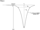
FIG. 3] FIG. 3 is a graph showing frequency characteristics of disturbance. - A
motor control device 11 according to an embodiment will be described. - As illustrated in
FIG. 1 , themotor control device 11 controls amotor 12. Themotor 12 generates torque for driving amechanical device 13 in which themotor 12 is to be installed. Themotor 12 is, for example, a three-phase brushless motor. Themotor 12 has arotation angle sensor 12A. Therotation angle sensor 12A detects a rotation angle θ of themotor 12. The rotation angle θ of themotor 12 is rotation information of themotor 12. - The
motor control device 11 has amicrocomputer 21, aninverter 22, and acurrent sensor 23. - The
microcomputer 21, which is a processing circuit, has a commandvalue calculation unit 31 and afeedback calculation unit 32. These calculation units are functional parts realized by a CPU (central processing unit) of themicrocomputer 21 executing a control program. Themicrocomputer 21 includes memory that stores the control program. The memory includes computer-readable media such as RAM (Random Access Memory) and ROM (Read Only Memory). However, each calculation unit being realized by software is only an example, and at least part of the calculation units may be realized by a hardware circuit such as a logic circuit. - The command
value calculation unit 31 calculates a current command value I* for themotor 12 based on a state variable Ssv indicating a state of themechanical device 13, for example. Thefeedback calculation unit 32 calculates a difference between the current command value I* calculated by the commandvalue calculation unit 31 and a value of a current Im of themotor 12 detected by way of thecurrent sensor 23. Thefeedback calculation unit 32 generates a drive signal for theinverter 22 so as to eliminate the difference between the current command value I* and the value of the current Im of themotor 12. - The
inverter 22 operates based on the drive signal generated by thefeedback calculation unit 32. Theinverter 22 has a plurality of switching elements. By switching these switching elements based on the drive signal, electric power according to the current command value I* is generated. The electric power generated by theinverter 22 is supplied to themotor 12 via a power supply path made up of a bus bar, a cable, or the like. Thus, themotor 12 generates torque corresponding to the current command value I*. - As illustrated in the block diagram of
FIG. 2 , themotor control device 11 has adisturbance observer unit 33. Thedisturbance observer unit 33 is provided to estimate a disturbance Tld that is applied to a plant P, which is an object of control, and to compensate for effects of the disturbance Tld. Compensation for the effects of disturbance refers to reducing the effects of disturbance by taking into account characteristics of the disturbance when controlling a system that is subject to disturbance. The disturbance Tld is nonlinear torque. The disturbance Tld is, for example, a torque ripple of themotor 12. Torque ripple is a disturbance that occurs periodically as themotor 12 rotates. - A control system for the
motor 12 is a feedback control system that determines the current command value I* for themotor 12 based on the state variable Ssv of themechanical device 13. Supplying current from theinverter 22 to themotor 12 in accordance with the current command value I* rotates themotor 12 at a predetermined angular velocity ωm. Therefore, a range from the current command value I* for themotor 12, to the angular velocity ωm of themotor 12, is the object of control target in the feedback control system. The angular velocity ωm of themotor 12 is rotation information of themotor 12. The plant P includes themechanical device 13. - When the inertial number of the
mechanical device 13 is "1", and themechanical device 13 and themotor 12 are regarded as being connected via an elastic element, the object of control can be regarded as being a two-inertial system in which two moments of inertia are connected by the elastic element. In this case, the object of control has frequency characteristics that include one set of resonance characteristics and antiresonance characteristics. - Also, when the inertial number of the
mechanical device 13 is "2", and themechanical device 13 and themotor 12 are regarded as being connected via an elastic element, the object of control can be regarded as being a three-inertial system in which three moments of inertia are connected by the elastic element. In this case, the object of control has frequency characteristics that include two sets of resonance characteristics and antiresonance characteristics. - The
disturbance observer unit 33 takes in the current command value I*, which is a target value of the plant P, and output of the plant P. An example of the output of the plant P is the angular velocity ωm of themotor 12. The angular velocity ωm is obtained by differentiation of the rotation angle θ of themotor 12 that is detected by therotation angle sensor 12A. Thedisturbance observer unit 33 estimates the disturbance Tld based on the current command value I* and the angular velocity ωm of themotor 12. Thedisturbance observer unit 33 calculates a first correction value Ic1, for canceling out the disturbance Tld having a frequency that is the object of suppression. - The
disturbance observer unit 33 has anestimator 33A, amultiplier 33B, and asubtractor 33C. Thedisturbance observer unit 33 may be made up of a hardware circuit, such as a logic circuit. Thedisturbance observer unit 33 is also referred to as a disturbance observer circuit. Also, thedisturbance observer unit 33 may be a functional part realized by a CPU of a computer executing a control program. - The
estimator 33A has a nominal plant Pn, a first observer gain L1, and a second observer gain L2. The nominal plant Pn is a model simulating the plant P that is the object of control. Theestimator 33A calculates a difference Δw between the angular velocity ωm of themotor 12 obtained as the output of the plant P, and an estimated angular velocity ωm^ of themotor 12 obtained as output of the nominal plant Pn, as shown in the following Expression (1). The "^" indicates an estimated value.
estimator 33A multiplies the value of the difference Δw between the angular velocity ωm of themotor 12 and the estimated angular velocity ωm^ of themotor 12 by the second observer gain L2, as shown in the following Expression (2), thereby calculating a differential value dTld^ of an estimated disturbance Tld^.
estimator 33A calculates the estimated disturbance Tld^ by integration of the differential value dTld^ of the estimated disturbance Tld^. The nominal plant Pn calculates an estimated value ωm^ of the angular velocity ωm using the estimated disturbance Tld^, a value obtained by multiplying the value of the difference Δw by the first observer gain L1, and a viscosity coefficient C of themotor 12. - The
multiplier 33B calculates the first correction value Ic1, by multiplying the differential value dTld^ of the estimated disturbance Tld^ calculated by theestimator 33A, by a gain β. The first correction value Ic1, is a current value for canceling out the vibration due to the disturbance Tld. - The
subtractor 33C subtracts the first correction value Ic1, from the current command value I* to calculate a current command value I* in which the effects of the disturbance Tld have been compensated for. - The disturbance Tld that is applied to the
mechanical device 13 after the effects of the disturbance Tld have been compensated for by thedisturbance observer unit 33 is referred to as post-compensation disturbance Tlast. - The post-compensation disturbance Tlast is expressed by the following Expression (3).
Tlast = Tld - β · dTld ̂ = {Js2 + (-L2 · β) + L1 · J) s + L2} · Tld / {JS2 + -L2 · C + L1 · J) s + L2} · Js mechanical device 13 is modeled, "C" is a viscosity coefficient in which friction of themechanical device 13 is modeled, "s" is a Laplace operator, "L1" is first observer gain, "L2" is second observer gain, and "β" is gain. - As shown in the graph of
FIG. 3 , the post-compensation disturbance Tlast has a notch, which is a spike-like drop, in frequency characteristics thereof. The post-compensation disturbance Tlast has frequency characteristics corresponding to the antiresonance characteristics of the plant P. - The first observer gain L1 is expressed by the following Expression (4).

- The second observer gain L2 is expressed by the following Expression (5).

mechanical device 13 is modeled, and "w" is frequency. - The gain β is expressed by the following Expression (6).

- The value of the frequency w is set to the frequency of the disturbance Tld to be suppressed, and the frequency of the disturbance Tld to be suppressed is, for example, the center frequency fc of the notch in the disturbance Tld.
- Further, adjusting the value of the first observer gain L1 enables a width Wn of the notch in the disturbance Tld to be adjusted. Adjusting the value of the first parameter α in Expression (4) enables the value of the first observer gain L1 to be adjusted.
- Also, adjusting the value of the gain β enables a depth Dn of the notch in the disturbance Tld to be adjusted. Adjusting the value of the second parameter γ in Expression (6) enables the value of the gain β to be adjusted.
- The first observer gain L1 and the gain β are parameters that are adjusted to suppress vibrations due to the disturbance Tld having a specific frequency that is the object of suppression. Adjusting the value of the first observer gain L1 and the value of the gain β enables a conveyance rate of the disturbance Tld to the plant P to be adjusted. The value of the first observer gain L1 and the value of the gain β are adjusted so that the post-compensation disturbance Tlast has frequency characteristics corresponding to the antiresonance characteristics of the plant P. Inputting the post-compensation disturbance Tlast having frequency characteristics corresponding to the antiresonance characteristics of the plant P into the plant P theoretically enables the amplitude of vibrations of the
mechanical device 13 due to the disturbance Tld having a specific frequency that is the object of suppression to be set to "0". - Substituting Expressions (4), (5), and (6) into the above Expression (3) yields the following Expression (7).
Tlast={s2 + 2 · ω · α · (1-γ) · s + ω2 · Tid / {s2 + 2 · ω · α · s + ω2} - Note that the second term in the curly brackets in the numerator of Expression (7), "2 · w · α · (1 - γ) · s", corresponds to the second term in the curly brackets in the numerator of Expression (3), "(- L2 · β) + L1 · J) s". To adjust the value of the second parameter γ is also to adjust the value of the gain β.
- According to the present embodiment, the following effects can be obtained.
- (1) The
disturbance observer unit 33 estimates the disturbance Tld using a nominal plant Pn that is a model simulating the plant P, and corrects the current command value I* based on the disturbance Tld that is estimated. Thedisturbance observer unit 33 has parameters that are adjusted to suppress vibrations due to the disturbance Tld having the specific frequency that is the object of suppression. Adjusting these parameters enables compensating just for the effects of the disturbance Tld having the specific frequency that is the object of suppression. The parameters are adjusted so that the post-compensation disturbance Tlast has frequency characteristics corresponding to the antiresonance characteristics of the plant P. Inputting the post-compensation disturbance Tlast having frequency characteristics corresponding to the antiresonance characteristics of the plant P to the plant P enables vibrations occurring in the plant P to be suppressed or canceled out. - (2) The
disturbance observer unit 33 estimates the disturbance Tld applied to themechanical device 13 based on the current command value I* and the angular velocity ωm of themotor 12. Unlike in the case in which the rotation angle θ of themotor 12 is used, there is no need to calculate the midpoint of themotor 12. The midpoint of themotor 12 is the rotation angle θ of themotor 12 corresponding to the reference operating state of themechanical device 13. Accordingly, themotor control device 11 does not need to have a function of calculating the midpoint of themotor 12. - (2) The
disturbance observer unit 33 calculates the first correction value Ic1 for the current command value I* by multiplying the differential value dTld^ of the estimated disturbance Tld^ by the gain β. Multiplying the differential value dTld^ by the gain β is all that is necessary, and accordingly the first correction value Ic1, can be easily calculated. - (3) The post-compensation disturbance Tlast that is applied to the plant P after the effects of the disturbance Tld have been compensated for has conveyance characteristics expressed by the following Expression (A). This is based on Expression (3) above.
{Js2 + (-L2 · β)+ L1 · J) s + L2} / {Js2 + (-L2 · C + L1 · J) s + L2} · Js disturbance observer unit 33 is adjusted so that the value of the second term of the numerator of Expression (A) becomes "0" or a value closer to "0". Adjusting the value of the gain β enables the disturbance Tld to be suppressed more appropriately. - The present embodiment may be carried out modified as follows.
- As indicated by the long dashed double-short dashed lines in
FIG. 2 , thedisturbance observer unit 33 may have adisturbance feedback controller 33D and anadder 33E. Thedisturbance feedback controller 33D takes in the differential value dTld^ of the estimated disturbance Tld^ calculated by theestimator 33A, and calculates a second correction value Ic2 based on the differential value dTld^ of the estimated disturbance Tld^ that is taken in. The second correction value Ic2 is a current value corresponding to the estimated disturbance Tld^ which is the difference between the actual motor output and the estimated motor output. Theadder 33E calculates the final current command value I* by adding the second correction value Ic2 to the current command value I* obtained after the effects of the disturbance ld are compensated for. Thefeedback calculation unit 32 performs feedback control of the current supplied to themotor 12 based on the final current command value I*. Thus, the value of the current supplied to themotor 12 tracks the current command value I* more quickly. - The
mechanical device 13 may be an electric power steering system. Themotor 12 is an assisting motor. The assisting motor generates assisting torque that is applied to the steering mechanism of the vehicle. The assisting torque is a torque for assisting steering by the steering wheel. The steering mechanism includes a steering shaft connected to steering wheels, and a turning shaft that steers the steered wheels of the vehicle. The assisting torque is applied to the steering shaft or the turning shaft. The commandvalue calculation unit 31 calculates the current command value I* for the assisting motor, in accordance with steering torque Th detected by the torque sensor. The steering torque Th is the torque applied to the steering wheel. The steering torque Th is a state variable Ssv indicating the steering state of the steering system. - The
mechanical device 13 may be a steer-by-wire steering system. Themotor 12 is a reaction force motor or a steering motor. The reaction force motor generates a steering reaction torque that is applied to the steering shaft of the vehicle. The steering reaction torque is a torque in an opposite direction of a steering direction of the steering wheel. The commandvalue calculation unit 31 calculates the current command value I* for the reaction force motor, in accordance with steering torque Th detected by the torque sensor. The steering motor generates steering torque for steering the steered wheels of the vehicle. The commandvalue calculation unit 31 calculates the current command value I* for the steering motor in accordance with the steering angle of the steering wheel. The steering angle is calculated, for example, based on the rotation angle θ of themotor 12 detected by therotation angle sensor 12A. The steering torque Th and the steering angle are the state variable Ssv indicating the steering state of the steering system. - As indicated by the long dashed double-short dashed lines in
FIG. 2 , when themotor 12 is an assisting motor or a reaction force motor, themotor control device 11 may be configured as follows. That is to say, themotor control device 11 has acompensator 34 and amultiplier 35. Thecompensator 34 calculates a torque differential value by differentiation of the steering torque Th detected by the torque sensor, and calculates a compensation amount dTca for compensating for the effects of the disturbance Tld in accordance with the torque differential value that is calculated. Themultiplier 35 calculates a third correction value Ic3 by multiplying the compensation amount dTca by the gain β. The third correction value Ic3 is a current value. Thesubtractor 33C adds the third correction value Ic3 to the current command value I*. This increases responsiveness of the motor torque as to changes in the steering torque Th. Thus, a smoother steering feel can be obtained. Also, advantages of suppressing disturbances, such as reverse input vibration from the steered wheels, brake vibrations generated due to brake operations, and so forth, can also be obtained. - When the
mechanical device 13 is a steering system of a vehicle, and themotor 12 is an assisting motor or a reaction force motor, thedisturbance observer unit 33 may be configured as follows. That is to say, thedisturbance observer unit 33 may stop disturbance compensation control, which is control for compensating for the effects of the disturbance Tld, in a state in which vibrations due to torque ripple of themotor 12 are unlikely to appear in the steering system. For example, vibrations due to torque ripple are easily conveyed to the steering system when the vehicle speed is an extremely low speed. Accordingly, thedisturbance observer unit 33 may stop the disturbance compensation control when a value of the vehicle speed exceeds a vehicle speed threshold. The speed threshold is a standard for determining whether the vehicle speed is an extremely low speed. Also, vibrations due to torque ripple are easily conveyed to the steering system when the angular velocity ωm of themotor 12 is extremely slow. Accordingly, thedisturbance observer unit 33 may stop the disturbance compensation control when a value of the angular velocity ωm exceeds an angular velocity threshold. The angular velocity threshold is a standard for when determining whether the angular velocity ωm of themotor 12 is extremely slow. The angular velocity ωm of themotor 12 reflects the steering speed of the steering wheel. - The
motor control device 11 may have a function of detecting an abnormality in itself, an abnormality in themotor 12, or an abnormality in themechanical device 13. In this case, thedisturbance observer unit 33 may stop the disturbance compensation control when an abnormality in themotor control device 11, themotor 12, or themechanical device 13, is detected. Executing compensation control when an abnormality is detected in themotor control device 11, themotor 12, or themechanical device 13, is meaningless. - The command
value calculation unit 31 may be configured as follows. That is to say, an arrangement may be made in which the commandvalue calculation unit 31 calculates a torque command value based on the state variable Ssv indicating the state of themechanical device 13, and calculates the current command value I* based on this torque command value that is calculated. The torque command value is the torque that themotor 12 is to be caused to generate. In this case, theestimator 33A takes in the torque command value and the angular velocity ωm of themotor 12, which is the output of the plant P. Theestimator 33A calculates the differential value dTld^ of the estimated disturbance Tld^ based on the torque command value and the angular velocity ωm of themotor 12. Themultiplier 33B calculates a torque correction value by multiplying the differential value dTld^ of the estimated disturbance Tld^ by a predetermined gain. The torque correction value is a correction value for the torque command value. Thesubtractor 33C corrects the torque command value by subtracting the torque correction value from the torque command value. In this arrangement as well, the effects of the disturbance Tld having the frequency that is the object of suppression can be compensated for. - The
disturbance observer unit 33 may be configured as follows. That is to say, thedisturbance observer unit 33 may calculate the difference between the rotation angle θ of themotor 12 obtained as the output of the plant P and the estimated rotation angle of themotor 12 obtained as the output of the nominal plant Pn, and compensate for the effects of the disturbance Tld based on the difference value that is calculated in this way. The rotation angle θ of themotor 12 is rotation information of themotor 12. - The
mechanical device 13 is not limited to being a vehicle steering system. Themechanical device 13 may be a machine tool driven by a motor, for example.
Claims (7)
- A motor control device that controls a motor of a mechanical device, the motor control device comprising:a command value calculation unit configured to calculate a command value for controlling the motor; anda disturbance observer unit configured to estimate a disturbance applied to the mechanical device, based on the command value and rotation information of the motor, and to correct the command value based on the disturbance that is estimated, whereinthe disturbance observer unit has a parameter that is adjusted to compensate for effects of the disturbance having a specific frequency that is an object of suppression,the disturbance that is applied to the mechanical device, after the effects of the disturbance have been compensated for, is a post-compensation disturbance, andthe parameter is adjusted such that the post-compensation disturbance has a frequency characteristic corresponding to an antiresonance characteristic of the mechanical device.
- The motor control device according to claim 1, wherein the rotation information of the motor is an angular velocity of the motor.
- The motor control device according to claim 2, wherein the disturbance observer unit is configured tocalculate a differential value of the disturbance based on the command value and the angular velocity of the motor, andcalculate a first correction value for the command value by multiplying, by a gain, the differential value of the disturbance that is calculated.
- The motor control device according to claim 3, wherein with "J" as a coefficient of inertia of the mechanical device, "C" as a viscosity coefficient of the mechanical device, "s" as a Laplace operator, "L1" as a first observer gain of the disturbance observer unit, "L2" as a second observer gain of the disturbance observer unit, and "β" as the gain, the post-compensation disturbance has conveyance characteristics expressed by the following Expression (A) {Js2 + (-L2 · β) + L1 · J) s + L2} / {Js2 + (-L2 · C + L1 · J) s + L2} · Js ... (A), and a value of "β" that is the gain is adjusted such that a value of a second term of a numerator of Expression (A) becomes zero or a value closer to zero.
- The motor control device according to any one of claims 2 to 4, wherein the disturbance observer is configured tocalculate a differential value of the disturbance based on the command value and the angular velocity of the motor, andcalculate a second correction value for the command value based on the differential value of the disturbance that is calculated.
- The motor control device according to any one of claims 1 to 5, wherein:the mechanical device is configured to also operate due to torque being applied externally; andthe disturbance observer unit is configured tocalculate a compensation amount for compensating for the effects of the disturbance in accordance with a differential value of the torque externally applied to the mechanical device, andcalculate a third correction value for the command value based on the compensation amount that is calculated.
- The motor control device according to any one of claims 1 to 6, wherein:the mechanical device is a steering system of a vehicle; andthe motor generates a torque that is applied to the steering system.
Applications Claiming Priority (1)
| Application Number | Priority Date | Filing Date | Title |
|---|---|---|---|
| PCT/JP2021/035661 WO2023053212A1 (en) | 2021-09-28 | 2021-09-28 | Motor control device |
Publications (2)
| Publication Number | Publication Date |
|---|---|
| EP4412079A1 true EP4412079A1 (en) | 2024-08-07 |
| EP4412079A4 EP4412079A4 (en) | 2024-11-20 |
Family
ID=85781481
Family Applications (1)
| Application Number | Title | Priority Date | Filing Date |
|---|---|---|---|
| EP21959260.7A Pending EP4412079A4 (en) | 2021-09-28 | 2021-09-28 | Motor control device |
Country Status (5)
| Country | Link |
|---|---|
| US (1) | US12594984B2 (en) |
| EP (1) | EP4412079A4 (en) |
| JP (1) | JP7768237B2 (en) |
| CN (1) | CN118056351A (en) |
| WO (1) | WO2023053212A1 (en) |
Cited By (1)
| Publication number | Priority date | Publication date | Assignee | Title |
|---|---|---|---|---|
| EP4496210A4 (en) * | 2022-03-16 | 2025-04-30 | JTEKT Corporation | ENGINE CONTROL DEVICE |
Family Cites Families (9)
| Publication number | Priority date | Publication date | Assignee | Title |
|---|---|---|---|---|
| JPH07123505A (en) | 1993-10-26 | 1995-05-12 | Hitachi Ltd | Current collector with active control |
| JPH0974783A (en) * | 1995-08-31 | 1997-03-18 | Nec Corp | Control apparatus for motor |
| JP2004224129A (en) | 2003-01-21 | 2004-08-12 | Koyo Seiko Co Ltd | Electric power steering device |
| JP4914979B2 (en) * | 2007-03-14 | 2012-04-11 | 国立大学法人長岡技術科学大学 | Motor control device and motor control method |
| JP2011160574A (en) | 2010-02-02 | 2011-08-18 | Meidensha Corp | Speed control device for motor |
| JP6491497B2 (en) | 2015-02-26 | 2019-03-27 | 山洋電気株式会社 | Motor control device |
| WO2019151200A1 (en) | 2018-01-31 | 2019-08-08 | 日本精工株式会社 | Motor control device and electric power steering device equipped with same |
| JP7294813B2 (en) | 2019-01-10 | 2023-06-20 | 株式会社ジェイテクト | Rudder control device |
| JP6977849B1 (en) * | 2020-09-30 | 2021-12-08 | 株式会社明電舎 | Vibration suppression control device and vibration suppression control method for vehicle system |
-
2021
- 2021-09-28 US US18/693,634 patent/US12594984B2/en active Active
- 2021-09-28 CN CN202180102757.XA patent/CN118056351A/en active Pending
- 2021-09-28 JP JP2023550797A patent/JP7768237B2/en active Active
- 2021-09-28 WO PCT/JP2021/035661 patent/WO2023053212A1/en not_active Ceased
- 2021-09-28 EP EP21959260.7A patent/EP4412079A4/en active Pending
Cited By (1)
| Publication number | Priority date | Publication date | Assignee | Title |
|---|---|---|---|---|
| EP4496210A4 (en) * | 2022-03-16 | 2025-04-30 | JTEKT Corporation | ENGINE CONTROL DEVICE |
Also Published As
| Publication number | Publication date |
|---|---|
| US20240391520A1 (en) | 2024-11-28 |
| US12594984B2 (en) | 2026-04-07 |
| JP7768237B2 (en) | 2025-11-12 |
| EP4412079A4 (en) | 2024-11-20 |
| JPWO2023053212A1 (en) | 2023-04-06 |
| WO2023053212A1 (en) | 2023-04-06 |
| CN118056351A (en) | 2024-05-17 |
Similar Documents
| Publication | Publication Date | Title |
|---|---|---|
| CN109572807B (en) | Electric power steering apparatus | |
| EP1808359B1 (en) | Electric power steering apparatus | |
| US9694844B2 (en) | Electric power steering system | |
| CN106004989B (en) | Electric power steering apparatus and gain setting method thereof | |
| EP2998198B1 (en) | Electric power steering system | |
| US9205862B2 (en) | Steering control device | |
| JP6413723B2 (en) | Electric power steering device | |
| EP1923298A1 (en) | Electronic power steering apparatus | |
| US20150175193A1 (en) | In-Vehicle Electronic Control Apparatus | |
| JP5408469B2 (en) | Motor control device | |
| EP2567881B1 (en) | Inertia compensation with frequency dependent damping | |
| EP4496210A1 (en) | Motor control device | |
| CN113371060A (en) | Steering control device | |
| JP5440845B2 (en) | Motor control device and vehicle steering device | |
| EP1863163B1 (en) | Motor controller | |
| US11541931B2 (en) | Control apparatus for motor | |
| US12594984B2 (en) | Motor control device | |
| US11370477B2 (en) | Electric power steering device | |
| JP5641299B2 (en) | Motor control device and vehicle steering device | |
| US11472469B2 (en) | Electric power steering device | |
| WO2026033730A1 (en) | Motor control device | |
| JP2008056079A (en) | Motor control device | |
| JP2026028439A (en) | Motor control device |
Legal Events
| Date | Code | Title | Description |
|---|---|---|---|
| STAA | Information on the status of an ep patent application or granted ep patent |
Free format text: STATUS: THE INTERNATIONAL PUBLICATION HAS BEEN MADE |
|
| PUAI | Public reference made under article 153(3) epc to a published international application that has entered the european phase |
Free format text: ORIGINAL CODE: 0009012 |
|
| STAA | Information on the status of an ep patent application or granted ep patent |
Free format text: STATUS: REQUEST FOR EXAMINATION WAS MADE |
|
| 17P | Request for examination filed |
Effective date: 20240322 |
|
| AK | Designated contracting states |
Kind code of ref document: A1 Designated state(s): AL AT BE BG CH CY CZ DE DK EE ES FI FR GB GR HR HU IE IS IT LI LT LU LV MC MK MT NL NO PL PT RO RS SE SI SK SM TR |
|
| A4 | Supplementary search report drawn up and despatched |
Effective date: 20241021 |
|
| RIC1 | Information provided on ipc code assigned before grant |
Ipc: H02P 23/14 20060101ALI20241015BHEP Ipc: H02P 23/12 20060101ALI20241015BHEP Ipc: H02P 21/20 20160101ALI20241015BHEP Ipc: H02P 21/13 20060101ALI20241015BHEP Ipc: H02P 6/10 20060101ALI20241015BHEP Ipc: H02P 23/04 20060101AFI20241015BHEP |
|
| DAV | Request for validation of the european patent (deleted) | ||
| DAX | Request for extension of the european patent (deleted) |