EP4411960A1 - Battery module, and battery pack and vehicle comprising same - Google Patents
Battery module, and battery pack and vehicle comprising same Download PDFInfo
- Publication number
- EP4411960A1 EP4411960A1 EP23858420.5A EP23858420A EP4411960A1 EP 4411960 A1 EP4411960 A1 EP 4411960A1 EP 23858420 A EP23858420 A EP 23858420A EP 4411960 A1 EP4411960 A1 EP 4411960A1
- Authority
- EP
- European Patent Office
- Prior art keywords
- battery
- case
- battery cells
- interrupt
- interrupt member
- Prior art date
- Legal status (The legal status is an assumption and is not a legal conclusion. Google has not performed a legal analysis and makes no representation as to the accuracy of the status listed.)
- Pending
Links
Images







Classifications
-
- H—ELECTRICITY
- H01—ELECTRIC ELEMENTS
- H01M—PROCESSES OR MEANS, e.g. BATTERIES, FOR THE DIRECT CONVERSION OF CHEMICAL ENERGY INTO ELECTRICAL ENERGY
- H01M50/00—Constructional details or processes of manufacture of the non-active parts of electrochemical cells other than fuel cells, e.g. hybrid cells
- H01M50/30—Arrangements for facilitating escape of gases
- H01M50/383—Flame arresting or ignition-preventing means
-
- H—ELECTRICITY
- H01—ELECTRIC ELEMENTS
- H01M—PROCESSES OR MEANS, e.g. BATTERIES, FOR THE DIRECT CONVERSION OF CHEMICAL ENERGY INTO ELECTRICAL ENERGY
- H01M50/00—Constructional details or processes of manufacture of the non-active parts of electrochemical cells other than fuel cells, e.g. hybrid cells
- H01M50/20—Mountings; Secondary casings or frames; Racks, modules or packs; Suspension devices; Shock absorbers; Transport or carrying devices; Holders
- H01M50/204—Racks, modules or packs for multiple batteries or multiple cells
-
- B—PERFORMING OPERATIONS; TRANSPORTING
- B60—VEHICLES IN GENERAL
- B60R—VEHICLES, VEHICLE FITTINGS, OR VEHICLE PARTS, NOT OTHERWISE PROVIDED FOR
- B60R16/00—Electric or fluid circuits specially adapted for vehicles and not otherwise provided for; Arrangement of elements of electric or fluid circuits specially adapted for vehicles and not otherwise provided for
- B60R16/02—Electric or fluid circuits specially adapted for vehicles and not otherwise provided for; Arrangement of elements of electric or fluid circuits specially adapted for vehicles and not otherwise provided for electric constitutive elements
- B60R16/03—Electric or fluid circuits specially adapted for vehicles and not otherwise provided for; Arrangement of elements of electric or fluid circuits specially adapted for vehicles and not otherwise provided for electric constitutive elements for supply of electrical power to vehicle subsystems or for
- B60R16/033—Electric or fluid circuits specially adapted for vehicles and not otherwise provided for; Arrangement of elements of electric or fluid circuits specially adapted for vehicles and not otherwise provided for electric constitutive elements for supply of electrical power to vehicle subsystems or for characterised by the use of electrical cells or batteries
-
- H—ELECTRICITY
- H01—ELECTRIC ELEMENTS
- H01M—PROCESSES OR MEANS, e.g. BATTERIES, FOR THE DIRECT CONVERSION OF CHEMICAL ENERGY INTO ELECTRICAL ENERGY
- H01M10/00—Secondary cells; Manufacture thereof
- H01M10/60—Heating or cooling; Temperature control
- H01M10/61—Types of temperature control
- H01M10/613—Cooling or keeping cold
-
- H—ELECTRICITY
- H01—ELECTRIC ELEMENTS
- H01M—PROCESSES OR MEANS, e.g. BATTERIES, FOR THE DIRECT CONVERSION OF CHEMICAL ENERGY INTO ELECTRICAL ENERGY
- H01M10/00—Secondary cells; Manufacture thereof
- H01M10/60—Heating or cooling; Temperature control
- H01M10/64—Heating or cooling; Temperature control characterised by the shape of the cells
- H01M10/647—Prismatic or flat cells, e.g. pouch cells
-
- H—ELECTRICITY
- H01—ELECTRIC ELEMENTS
- H01M—PROCESSES OR MEANS, e.g. BATTERIES, FOR THE DIRECT CONVERSION OF CHEMICAL ENERGY INTO ELECTRICAL ENERGY
- H01M10/00—Secondary cells; Manufacture thereof
- H01M10/60—Heating or cooling; Temperature control
- H01M10/65—Means for temperature control structurally associated with the cells
- H01M10/658—Means for temperature control structurally associated with the cells by thermal insulation or shielding
-
- H—ELECTRICITY
- H01—ELECTRIC ELEMENTS
- H01M—PROCESSES OR MEANS, e.g. BATTERIES, FOR THE DIRECT CONVERSION OF CHEMICAL ENERGY INTO ELECTRICAL ENERGY
- H01M50/00—Constructional details or processes of manufacture of the non-active parts of electrochemical cells other than fuel cells, e.g. hybrid cells
- H01M50/10—Primary casings; Jackets or wrappings
- H01M50/14—Primary casings; Jackets or wrappings for protecting against damage caused by external factors
- H01M50/143—Fireproof; Explosion-proof
-
- H—ELECTRICITY
- H01—ELECTRIC ELEMENTS
- H01M—PROCESSES OR MEANS, e.g. BATTERIES, FOR THE DIRECT CONVERSION OF CHEMICAL ENERGY INTO ELECTRICAL ENERGY
- H01M50/00—Constructional details or processes of manufacture of the non-active parts of electrochemical cells other than fuel cells, e.g. hybrid cells
- H01M50/20—Mountings; Secondary casings or frames; Racks, modules or packs; Suspension devices; Shock absorbers; Transport or carrying devices; Holders
- H01M50/204—Racks, modules or packs for multiple batteries or multiple cells
- H01M50/207—Racks, modules or packs for multiple batteries or multiple cells characterised by their shape
- H01M50/211—Racks, modules or packs for multiple batteries or multiple cells characterised by their shape adapted for pouch cells
-
- H—ELECTRICITY
- H01—ELECTRIC ELEMENTS
- H01M—PROCESSES OR MEANS, e.g. BATTERIES, FOR THE DIRECT CONVERSION OF CHEMICAL ENERGY INTO ELECTRICAL ENERGY
- H01M50/00—Constructional details or processes of manufacture of the non-active parts of electrochemical cells other than fuel cells, e.g. hybrid cells
- H01M50/20—Mountings; Secondary casings or frames; Racks, modules or packs; Suspension devices; Shock absorbers; Transport or carrying devices; Holders
- H01M50/249—Mountings; Secondary casings or frames; Racks, modules or packs; Suspension devices; Shock absorbers; Transport or carrying devices; Holders specially adapted for aircraft or vehicles, e.g. cars or trains
-
- H—ELECTRICITY
- H01—ELECTRIC ELEMENTS
- H01M—PROCESSES OR MEANS, e.g. BATTERIES, FOR THE DIRECT CONVERSION OF CHEMICAL ENERGY INTO ELECTRICAL ENERGY
- H01M50/00—Constructional details or processes of manufacture of the non-active parts of electrochemical cells other than fuel cells, e.g. hybrid cells
- H01M50/20—Mountings; Secondary casings or frames; Racks, modules or packs; Suspension devices; Shock absorbers; Transport or carrying devices; Holders
- H01M50/258—Modular batteries; Casings provided with means for assembling
-
- H—ELECTRICITY
- H01—ELECTRIC ELEMENTS
- H01M—PROCESSES OR MEANS, e.g. BATTERIES, FOR THE DIRECT CONVERSION OF CHEMICAL ENERGY INTO ELECTRICAL ENERGY
- H01M50/00—Constructional details or processes of manufacture of the non-active parts of electrochemical cells other than fuel cells, e.g. hybrid cells
- H01M50/20—Mountings; Secondary casings or frames; Racks, modules or packs; Suspension devices; Shock absorbers; Transport or carrying devices; Holders
- H01M50/289—Mountings; Secondary casings or frames; Racks, modules or packs; Suspension devices; Shock absorbers; Transport or carrying devices; Holders characterised by spacing elements or positioning means within frames, racks or packs
- H01M50/291—Mountings; Secondary casings or frames; Racks, modules or packs; Suspension devices; Shock absorbers; Transport or carrying devices; Holders characterised by spacing elements or positioning means within frames, racks or packs characterised by their shape
-
- H—ELECTRICITY
- H01—ELECTRIC ELEMENTS
- H01M—PROCESSES OR MEANS, e.g. BATTERIES, FOR THE DIRECT CONVERSION OF CHEMICAL ENERGY INTO ELECTRICAL ENERGY
- H01M50/00—Constructional details or processes of manufacture of the non-active parts of electrochemical cells other than fuel cells, e.g. hybrid cells
- H01M50/30—Arrangements for facilitating escape of gases
- H01M50/342—Non-re-sealable arrangements
- H01M50/3425—Non-re-sealable arrangements in the form of rupturable membranes or weakened parts, e.g. pierced with the aid of a sharp member
-
- H—ELECTRICITY
- H01—ELECTRIC ELEMENTS
- H01M—PROCESSES OR MEANS, e.g. BATTERIES, FOR THE DIRECT CONVERSION OF CHEMICAL ENERGY INTO ELECTRICAL ENERGY
- H01M50/00—Constructional details or processes of manufacture of the non-active parts of electrochemical cells other than fuel cells, e.g. hybrid cells
- H01M50/30—Arrangements for facilitating escape of gases
- H01M50/35—Gas exhaust passages comprising elongated, tortuous or labyrinth-shaped exhaust passages
- H01M50/358—External gas exhaust passages located on the battery cover or case
-
- H—ELECTRICITY
- H01—ELECTRIC ELEMENTS
- H01M—PROCESSES OR MEANS, e.g. BATTERIES, FOR THE DIRECT CONVERSION OF CHEMICAL ENERGY INTO ELECTRICAL ENERGY
- H01M50/00—Constructional details or processes of manufacture of the non-active parts of electrochemical cells other than fuel cells, e.g. hybrid cells
- H01M50/30—Arrangements for facilitating escape of gases
- H01M50/35—Gas exhaust passages comprising elongated, tortuous or labyrinth-shaped exhaust passages
- H01M50/367—Internal gas exhaust passages forming part of the battery cover or case; Double cover vent systems
-
- H—ELECTRICITY
- H01—ELECTRIC ELEMENTS
- H01M—PROCESSES OR MEANS, e.g. BATTERIES, FOR THE DIRECT CONVERSION OF CHEMICAL ENERGY INTO ELECTRICAL ENERGY
- H01M50/00—Constructional details or processes of manufacture of the non-active parts of electrochemical cells other than fuel cells, e.g. hybrid cells
- H01M50/50—Current conducting connections for cells or batteries
- H01M50/502—Interconnectors for connecting terminals of adjacent batteries; Interconnectors for connecting cells outside a battery casing
- H01M50/505—Interconnectors for connecting terminals of adjacent batteries; Interconnectors for connecting cells outside a battery casing comprising a single busbar
-
- H—ELECTRICITY
- H01—ELECTRIC ELEMENTS
- H01M—PROCESSES OR MEANS, e.g. BATTERIES, FOR THE DIRECT CONVERSION OF CHEMICAL ENERGY INTO ELECTRICAL ENERGY
- H01M50/00—Constructional details or processes of manufacture of the non-active parts of electrochemical cells other than fuel cells, e.g. hybrid cells
- H01M50/50—Current conducting connections for cells or batteries
- H01M50/502—Interconnectors for connecting terminals of adjacent batteries; Interconnectors for connecting cells outside a battery casing
- H01M50/507—Interconnectors for connecting terminals of adjacent batteries; Interconnectors for connecting cells outside a battery casing comprising an arrangement of two or more busbars within a container structure, e.g. busbar modules
-
- H—ELECTRICITY
- H01—ELECTRIC ELEMENTS
- H01M—PROCESSES OR MEANS, e.g. BATTERIES, FOR THE DIRECT CONVERSION OF CHEMICAL ENERGY INTO ELECTRICAL ENERGY
- H01M2220/00—Batteries for particular applications
- H01M2220/20—Batteries in motive systems, e.g. vehicle, ship, plane
-
- Y—GENERAL TAGGING OF NEW TECHNOLOGICAL DEVELOPMENTS; GENERAL TAGGING OF CROSS-SECTIONAL TECHNOLOGIES SPANNING OVER SEVERAL SECTIONS OF THE IPC; TECHNICAL SUBJECTS COVERED BY FORMER USPC CROSS-REFERENCE ART COLLECTIONS [XRACs] AND DIGESTS
- Y02—TECHNOLOGIES OR APPLICATIONS FOR MITIGATION OR ADAPTATION AGAINST CLIMATE CHANGE
- Y02E—REDUCTION OF GREENHOUSE GAS [GHG] EMISSIONS, RELATED TO ENERGY GENERATION, TRANSMISSION OR DISTRIBUTION
- Y02E60/00—Enabling technologies; Technologies with a potential or indirect contribution to GHG emissions mitigation
- Y02E60/10—Energy storage using batteries
Definitions
- the present disclosure relates to a battery module, and a battery pack and a vehicle comprising the same, and more particularly, to a battery module with improved safety and a battery pack and a vehicle comprising the same.
- secondary batteries Due to being easily applicable to various products and having electrical properties such as high energy density, secondary batteries are commonly applied to not only portable devices but also electric vehicles (EVs) or hybrid electric vehicles (HEVs) that are driven by an electrical driving source. Secondary batteries remarkably reduce the use of fossil fuels, and in addition to the primary advantage, they do not generate by-products from the use of energy. From this perspective, secondary batteries are seen as a new source of energy with eco-friendliness and energy efficiency.
- EVs electric vehicles
- HEVs hybrid electric vehicles
- a unit secondary battery cell or a unit battery cell has an operating voltage of about 2.5V to 4.5V. Accordingly, when higher output voltage is required, a plurality of battery cells may be connected in series to form a battery pack. Additionally, the battery pack may be fabricated by connecting the plurality of battery cells in parallel according to the charge/discharge capacity required for the battery pack. Accordingly, the number of battery cells included in the battery pack may be variously set depending on the required output voltage or charge/discharge capacity.
- the battery pack when fabricating the battery pack by connecting the plurality of battery cells in series/in parallel, it is general to make a battery module including at least one battery cell, and then make a battery pack or a battery rack using at least one battery module with an addition of any other component.
- the plurality of secondary batteries (battery cells) or the plurality of battery modules densely arranged in a narrow space may be vulnerable to thermal events.
- an event such as thermal runaway occurs in any one battery cell
- high temperature gases, flames or heat may be produced.
- gases, flames or heat are transferred to other battery cells included in the same battery module, explosive chain reaction such as thermal propagation may occur.
- the chain reaction may cause an accident such as fire or explosion in not only the corresponding battery module but also other battery module.
- medium and large-scale battery packs for electric vehicles include a large number of battery cells and a large number of battery modules to increase the output and/or capacity, and have a higher risk of thermal chain reaction.
- the battery packs for electric vehicles may be mounted near users such as drivers. When it fails to adequately control a thermal event in a specific battery module, causing chain reaction, not only economic loss but also human loss may occur.
- the present disclosure is directed to providing a battery module with improved safety against thermal events and a battery pack and a vehicle comprising the same.
- the present disclosure provides a battery module including a cell assembly including a plurality of battery cells stacked; a module case accommodating the cell assembly; and a busbar assembly coupled to the module case and electrically connected to the plurality of battery cells, wherein the cell assembly includes an interrupt member configured to cover a portion of the plurality of battery cells to prevent thermal propagation to adjacent battery cells in a stack direction of the plurality of battery cells upon an occurrence of a thermal event in at least one battery cell.
- the interrupt member may guide venting of vent materials emitted from the at least one battery cell in a specific direction upon the occurrence of the thermal event in the at least one battery cell.
- the module case may have at least one vent on bottom to vent the vent materials
- the interrupt member may have an open bottom to guide the venting of the vent materials toward the vent of the module case.
- the cell assembly may include a thermal barrier member disposed between the plurality of battery cells in the stack direction of the plurality of battery cells.
- the thermal barrier member may contact the interrupt member in the stack direction of the plurality of battery cells.
- two end portions of the interrupt member may be disposed close to the busbar assembly.
- the busbar assembly may cover two sides of the plurality of battery cells, and the two end portions of the interrupt member may be disposed close to the busbar assembly.
- the interrupt member may be made of a flexible material.
- the interrupt member may cover a top portion and two edge portions of the plurality of battery cells.
- the interrupt member may cover a front side portion and a rear side portion of the two edge portions of the plurality of battery cells in the stack direction of the plurality of battery cells.
- each of the plurality of battery cells may include an electrode assembly; a battery case including a case body accommodating the electrode assembly and a case terrace extending in a stepped manner from two sides of the case body; and a pair of electrode leads connected to the electrode assembly, protruding from the case terrace of the battery case and connected to the busbar assembly, and the interrupt member may cover a top portion of the case body, and a front side portion and a rear side portion of the case terrace.
- the top portion of the case body may have a sealing portion connected to the case terrace and configured to seal the case body, and the interrupt member may cover the sealing portion.
- the interrupt member may have a guide slit to allow the pair of electrode leads to pass through to prevent interference with the pair of electrode leads.
- the present disclosure provides a battery pack including at least one battery module according to the above-described embodiments; and a pack case accommodating the at least one battery module.
- the present disclosure provides a vehicle including at least one battery pack according to the above-described embodiment.
- FIG. 1 is a diagram illustrating a battery module 10 according to an embodiment of the present disclosure
- FIG. 2 is an exploded perspective view of the battery module 10 of FIG. 1
- FIG. 3 is a partial cross-sectional view illustrating a connected part of a cell assembly 100 and a busbar assembly 300 of the battery module 10 of FIG. 2 .
- the battery module 10 may include a cell assembly 100, a module case 200 and a busbar assembly 300.
- the cell assembly 100 may include a plurality of battery cells 110 stacked.
- the plurality of battery cells 110 may be electrically connected to each other and connected to the busbar assembly 300 as described below.
- the plurality of battery cells 110 may be secondary batteries, for example, pouch type secondary batteries.
- the module case 200 may form the appearance of the battery module 10 and accommodate the cell assembly 100. To this end, the module case 200 may have an accommodation space for accommodating the cell assembly 100.
- the busbar assembly 300 may be coupled to the module case 200 to form the appearance of the battery module 10 together with the module case 200.
- the busbar assembly 300 may be electrically connected to the plurality of battery cells 110 of the cell assembly 100 to sense the voltage of the plurality of battery cells 110.
- the cell assembly 100 may include an interrupt member 130.
- the interrupt member 130 may be configured to cover a portion of the plurality of battery cells 110 to prevent thermal propagation to the adjacent battery cells 110 in the stack direction (Y axis direction) of the plurality of battery cells 110 when a thermal event occurs due to an abnormal situation such as overheating in at least one of the battery cells 110.
- the battery cell 110 in which the abnormal situation occurred may have high temperature due to overheating and produce vent materials such as flames or gases.
- vent materials such as heat, flames or gases from the specific battery cell 110 spread to the adjacent battery cell 110, thermal runaway occurs in the adjacent battery cell 110, posing a bigger risk such as fire spread or explosion in the battery cells 110.
- the battery module 10 may effectively prevent the spread of the vent materials such as heat, flames or gases produced from the battery cell 110 in which the abnormal situation occurred to the adjacent battery cell 110 through the interrupt member 130 covering the portion of the plurality of battery cells 110 when the thermal event occurred.
- the battery module 10 may minimize secondary damage risks such as fire spread or explosion that may occur when the thermal event occurs through the interrupt member 130.
- the interrupt member 130 may guide the venting of the vent materials emitted from the at least one battery cell 110 in a specific direction when the thermal event occurs in the at least one battery cell 110.
- the vent materials such as flames or gases may be produced in the battery cell 110 or the module case 200 in which the abnormal situation occurred.
- the vent materials may increase the pressure in the module case 200 of the battery module 10 or explode the adjacent components. Accordingly, it is necessary to vent the vent materials out of the module case 200 quickly when the thermal event occurs. Additionally, in addition to fast venting of the vent materials out of the module case 200, it is important to control the venting direction of the vent materials in order to minimize damage to the components inside the module case 200.
- the interrupt member 130 may prevent thermal propagation of the adjacent battery cell 110 and guide the venting direction of the vent materials, i.e., guide the venting of the vent materials in a specific direction. That is, the interrupt member 130 may control the venting path of the vent materials such as gases or flames by guiding the directional venting in the specific direction to force the vent materials out of the module case 200 more quickly.
- the module case 200 may have at least one vent 215 on bottom (-Z axis direction) to force the vent materials out.
- a plurality of vents 215 may be provided, and disposed at two sides on the bottom of the module case 200.
- the vent 215 may force the vent materials such as flames or gases in the module case 200 out of the module case 200 when the thermal event occurs.
- the vent 215 may be a vent hole having a predetermined opening or a venting unit that may be mounted in the module case 200. Meanwhile, the vent 215 may be structured to melt or break open at or above a predetermined temperature or a predetermined pressure to bring the inside and outside of the module case 200 into communication with each other when the thermal event occurs.
- the interrupt member 130 may have the open bottom to guide the venting of the vent materials toward the vent 215 of the module case 200.
- the vent materials may be guided toward the vent 215 on the bottom of the module case 200 through the open bottom of the interrupt member 130 and exit the vent 215 quickly.
- the interrupt member 130 may guide the vent materials such as gases or flames produced when the thermal event occurs in the specific direction, specifically, a downward direction (-Z axis direction) of the battery module 10 and force them out the battery module 10.
- FIG. 4 is a diagram illustrating the cell assembly 100 of the battery module 10 of FIG. 1 .
- the cell assembly 100 may include a thermal barrier member 150.
- the thermal barrier member 150 may be disposed between the plurality of battery cells 110 in the stack direction (Y axis direction) of the plurality of battery cells 110.
- the thermal barrier member 150 may prevent the transfer of heat, gases or flames from the battery cell 110 in which the abnormal situation occurred when the thermal event occurred to the adjacent battery cell 110 together with the interrupt member 130.
- a plurality of thermal barrier members 150 may be provided, and may have a sufficient size to cover the battery cells 110 in the stack direction (Y axis direction) of the battery cells 110.
- the thermal barrier member 150 may be contacted to the interrupt member 130 in the stack direction (Y axis direction) of the plurality of battery cells 110. Accordingly, the plurality of battery cells 110 may be surrounded by the interrupt member 130 and the thermal barrier member 150 excluding the open bottom of the interrupt member 130 and a guide slit 135 area as described below.
- the battery module 10 may prevent thermal propagation to the battery cell 110 adjacent to the battery cell 110 in which the abnormal situation occurred when the thermal event occurs more effectively through the interrupt member 130 and the thermal barrier member 150.
- a portion of the interrupt member 130 may be disposed close to the busbar assembly 300.
- two end portions of the interrupt member 130 may be disposed close to the busbar assembly 300.
- the busbar assembly 300 may cover two sides (X axis direction) of the plurality of battery cells 110.
- the two end portions of the interrupt member 130 may be disposed adjacent to the busbar assembly 300.
- the interrupt member 130 may be made of a flexible material. Accordingly, the interrupt member 130 may increase the mounting convenience with the battery cells 110 and absorb or cancel off an assembly tolerance with the adjacent components when mounting. Additionally, the interrupt member 130 may have a predetermined level of elasticity to buffer external impacts that may be applied to the battery cells 110.
- the interrupt member 130 may include a fire resistant material.
- the interrupt member 130 may include glass fiber, rubber or silicone. This is provided by way of illustration, and the interrupt member 130 may include any other material having flexibility and fire resistance.
- the interrupt member 130 may include an insulation material. Accordingly, the interrupt member 130 may effectively prevent electricity conduction from the battery cell 110 in which the abnormal situation occurred to the adjacent battery cell 110. Additionally, the interrupt member 130 may include a flame retardant material. As described above, the interrupt member 130 may include fire resistant, insulation and flame retardant materials to increase the thermal propagation prevention or delay effect when the thermal event occurs.
- a plurality of interrupt members 130 corresponding to the number of battery cells 110 may be provided. Each of the plurality of interrupt members 130 may cover each of the portion of the plurality of battery cells 110. Accordingly, in an embodiment of the present disclosure, since the plurality of the interrupt member 130 corresponding to the number of battery cells 110 is provided, thermal propagation prevention or delay and downward directional venting guide for each battery cell 110 may be uniformly achieved in any of the battery cells 110.
- FIG. 5 is a diagram illustrating the interrupt member 130 mounted in the battery cell 110 of the cell assembly 100 of FIG. 4
- FIG. 6 is a diagram illustrating the mounting of the interrupt member 130 onto the battery cell 110 of FIG. 5 .
- the interrupt member 130 may cover the top portion and two edge portions of the plurality of battery cells 110. Accordingly, the interrupt member 130 may effectively prevent thermal propagation to the adjacent battery cell 110 that may occur at the top and two edge portions of the plurality of battery cells 110 when the thermal event occurs. Additionally, the interrupt member 130 may guide the movement of the vent materials such as flames or gases produced when the thermal event occurs in the downward direction (-Z axis direction) of the battery cells 110 through the above-described cover structure.
- the interrupt member 130 may cover the front side portion (+Y axis direction) and the rear side portion (-Y axis direction) of the two edge portions of the plurality of battery cells 110 in the stack direction (Y axis direction) of the plurality of battery cells 110.
- the two edge portions of the plurality of battery cells 110 has a predetermined step space in one direction (+Y axis direction or -Y axis direction) of the front-rear direction (Y axis direction) and the front-rear direction (Y axis direction) according to the characterizing shape of the pouch type secondary battery.
- the vent materials produced when the thermal event occurs may enter and stay in the step space due to the convection. In case where the vent materials such as flames or gases may stay or build in the step space, there is a high risk that the vent materials spread to the adjacent battery cells 110, and a rapid rise in internal pressure of the module case 200 may increase the likelihood that secondary damage such as explosion may occur in the battery module 10.
- the interrupt member 130 covers the two edge portions of the battery cells 110 in the front-rear direction (Y axis direction), it may be possible to significantly reduce the total size of the step space in the stack direction (Y axis direction) of the battery cells 110. Accordingly, in an embodiment of the present disclosure, it may be possible to reduce the volume of the step space through the interrupt member 130, thereby reducing or preventing the vent materials such as flames or gases from entering the step space, and significantly reducing the likelihood that the vent materials such as flames or gases stay in the step space.
- vent 215 of the module case 200 may be disposed close to the step space on the bottom of the module case 200. This is to force the vent materials such as flames or gases in the step space out of the module case 200 more quickly.
- the plurality of battery cells 110 for example, the pouch type secondary batteries will be described in more detail.
- Each of the plurality of battery cells 110 may include an electrode assembly 111, a battery case 112 and a pair of electrode leads 117.
- the electrode assembly 111 may include a positive electrode plate, a negative electrode plate and a separator.
- the electrode assembly 111 is well known, and hereinafter, its detailed description is omitted.
- the battery case 112 may accommodate the electrode assembly 111. To this end, the battery case 112 may have an accommodation space for accommodating the electrode assembly 111.
- the battery case 112 may include a case body 113 and a case terrace 115.
- the case body 113 may accommodate the electrode assembly 111 and a portion of the pair of electrode leads 117 as described below.
- the case body 117 may have an accommodation space for accommodating the electrode assembly 111 and the portion of the pair of electrode leads 117.
- the case terrace 115 may extend from two sides of the case body 113.
- the case terrace 115 may be sealed through heat welding to make the case body 113 airtight.
- the case terrace 115 may extend in a stepped manner from the two sides of the case body 113 due to the volume of the electrode assembly 111 in the case body 113 and the sealing, to form a predetermined step from the case body 113.
- the predetermined step space may be formed at both the front side (+Y axis direction) and the rear side (-Y axis direction) of the case terrace 115.
- the pair of electrode leads 117 may be connected to the electrode assembly 111, and may protrude from the case terrace 115 of the battery case 112 and connect to the busbar assembly 300. In this embodiment, each of the pair of electrode leads 117 may protrude from each of two sides (X axis direction) of the case terrace 115 of the battery case 112.
- the interrupt member 130 may cover the top portion (+Z axis direction) of the case body 113 and the front side portion (+Y axis direction) and the rear side portion (-Y axis direction) of the case terrace 115. Accordingly, the interrupt member 130 may cover the battery cell 110 in a U shape with the open bottom.
- the top portion (+Z axis direction) of the case body 113 may have a sealing portion 114 connected to the case terrace 115 and configured to seal the case body 113.
- the sealing portion 114 may be folded at least once for the slim design of the battery cell 110.
- the interrupt member 130 may cover the sealing portion 114.
- the sealing portion 114 may be unintentionally opened, and in this instance, the vent materials such as flames or gases may leak out of the sealing portion 114.
- the interrupt member 130 since the interrupt member 130 covers the sealing portion 114, it may be possible to effectively prevent leakage of the vent materials such as flames or gases when the sealing portion 114 is opened.
- Each of the plurality of battery cells 110 may include a cell vent 118.
- the cell vent 118 may be configured to vent gases or flames when the abnormal situation occurs due to overheat in the battery cell 110, and disposed on one side of the battery case 112. Specifically, the cell vent 118 may be disposed at two sides on bottom (-Z axis direction) of the case body 113. The cell vent 118 may melt or break at or above the predetermined temperature or pressure to open the battery case 112 such that the inside of the battery case 112 is in communication with the outside.
- the cell vent 118 may be integrally formed in the battery case 112, and have a smaller thickness than other areas of the battery case 112 to melt or break more quickly. This is provided by way of illustration, and the cell vent 118 may be formed in the battery case 112 as a separate member and structured to open the battery case 112 when the thermal event occurs.
- the interrupt member 130 may have the guide slit 135 to allow the pair of electrode leads 117 to pass through to prevent interferences with the pair of electrode leads 117.
- the guide slit 135 may form a predetermined gap at the two end portions of the interrupt member 130.
- the guide slit 135 may guide easier electrical connection between the pair of electrode leads 117 and the busbar assembly 300.
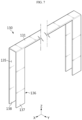
- FIG. 7 is a diagram illustrating the interrupt member 130 of FIG. 6
- FIG. 8 is a side view of the interrupt member 130 of FIG. 7 .
- the interrupt member 130 may include an interrupt cover 131 and an interrupt leg 136.
- the interrupt cover 131 may be formed with a predetermined length to cover the top portion (+Z axis direction) of the battery cell 110 (see FIG. 6 ). Additionally, the interrupt cover 131 may have at least the same width as the top width of the case body 113 of the battery case 112 of the battery cell 110 (see FIG. 6 ).
- the interrupt leg 136 may bend and extend downwards (-Z axis direction) from two end portions of the interrupt cover 131.
- the interrupt leg 136 may be integrally formed with the interrupt cover 131, and cover the two edge portions of the battery cell 110 (see FIG. 6 ) in the front-rear direction (Y axis direction).
- the interrupt leg 136 may include a first leg 137 and a second leg 138.
- the first leg 137 may be formed with a predetermined length at two front sides (+Y axis direction) of the interrupt cover 131.
- the second leg 138 may be spaced a predetermined distance apart from the first leg 137 in the front-rear direction (Y axis direction), and formed with a predetermined length at two rear sides (-Y axis direction) of the interrupt cover 131.
- the guide slit 135 may be formed by the gap between the first leg 137 and the second leg 138.
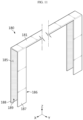
- FIG. 9 is a diagram illustrating an interrupt member 170 according to another embodiment of the present disclosure
- FIG. 10 is a side view of the interrupt member 170 of FIG. 9 .
- the interrupt member 170 according to this embodiment is similar to the interrupt member 130 of the previous embodiment, and regarding the components that are substantially identical or similar to the previous embodiment, redundant description is omitted, and hereinafter, difference(s) between this embodiment and the previous embodiment will be described.
- the interrupt member 170 may include an interrupt cover 171 and an interrupt leg 176.
- the interrupt cover 171 is similar to the interrupt cover 131 of the previous embodiment, and hereinafter, redundant description is omitted.
- the interrupt leg 176 may include a first leg 177 and a second leg 178.
- a thickness W1 of the first leg 177 may correspond to the step space formed at the front side (+Y axis direction) of the case terrace 115 (see FIG. 6 ) of the battery case 112 (see FIG. 6 ) of the battery cell 110 (see FIG. 6 ).
- the thickness W1 of the first leg 177 may be at least equal to the thickness of the step space formed at the front side (+Y axis direction) of the case terrace 115 (see FIG. 6 ).
- a thickness W2 of the second leg 178 may correspond to the step space formed at the rear side (-Y axis direction) of the case terrace 115 (see FIG. 6 ) of the battery case 112 (see FIG. 6 ) of the battery cell 110 (see FIG. 6 ).
- the thickness W2 of the second leg 178 may be at least equal to the thickness of the step space formed at the rear side (-Y axis direction) of the case terrace 115 (see FIG. 6 ).
- the guide slit 175 formed between the first leg 177 and the second leg 178 may have a thickness corresponding to the thickness of the case terrace 115 of the battery case 112 of the battery cell 110 (see FIG. 6 ).
- the interrupt member 170 may offset the step space in the front-rear direction (Y axis direction) of the case terrace 115 (see FIG. 6 ) of the battery case 112 (see FIG. 6 ) of the battery cell 110 (see FIG. 6 ) through the first leg 177 and the second leg 178 having the predetermined thickness W1, W2, thereby preventing the vent materials such as flames or gases from entering or staying in the step space more effectively.
- FIG. 11 is a diagram illustrating an interrupt member 180 according to still another embodiment of the present disclosure
- FIG. 12 is a side view of the interrupt member 180 of FIG. 11 .
- the interrupt member 180 according to this embodiment is similar to the interrupt member 130 of the previous embodiment, and regarding the components that are substantially identical or similar to the previous embodiment, redundant description is omitted, and hereinafter, difference(s) between this embodiment and the previous embodiment will be described.
- the interrupt member 180 may include an interrupt cover 181, an interrupt leg 186 and a coating layer 189.
- the interrupt cover 181 is similar to the interrupt cover 131 of the previous embodiment, and hereinafter, redundant description is omitted.
- the interrupt leg 186 may include a first leg 187 and a second leg 188.
- the first leg 187 and the second leg 188 are similar to each other, and hereinafter, redundant description is omitted.
- the coating layer 189 may be disposed on one surface of the interrupt member 180 facing the battery cell 110 when the interrupt member 180 is mounted in the battery cell 110 (see FIG. 6 ). Specifically, the coating layer 189 may be disposed on the inner surface of the interrupt cover 181, the inner surface of the first leg 187 and the inner surface of the second leg 188. The coating layer 189 may include a material having fire resistance and flame retardancy functions.
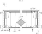
- FIG. 13 is a diagram illustrating the directional venting path of the vent materials such as flames or gases when the thermal event occurs due to the abnormal situation in the at least one battery cell 110 of the battery module 10 of FIG. 1
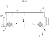
- FIG. 14 is a diagram illustrating the directional venting path of the vent materials such as flames or gases emitted from the battery cell 110 when the thermal event occurs as shown in FIG. 12
- FIG. 15 is a diagram illustrating thermal propagation prevention and directional venting guide through the interrupt member 130 when the thermal event occurs in the battery cell 110 in which the abnormal situation occurred as shown in FIG. 13 .
- vent materials G such as flames or gases may be produced when the thermal event occurs due to the abnormal situation in the at least one battery cell 110 of the battery module 10.
- the interrupt member 130 covers the top portion and the two edge portions of the battery cell 110 in which the abnormal situation occurred with the bottom open, it may be possible to guide the downward (-Z axis direction) movement of the vent materials G such as flames or gases emitted from the battery cell 110 in the abnormal situation. Subsequently, the vent materials G such as flames or gases may escape in the downward direction of the battery module 10 quickly through the vent 215 on the bottom of the module case 200.
- the vent materials G such as flames or gases
- the vent materials G such as flames or gases produced in the battery cell 110 in which the abnormal situation occurred may escape out of the battery cell 110 through the cell vent 118 at two sides on the bottom of the case body 113 of the battery case 112.
- the cell vent 118 is disposed at the two sides on the bottom of the battery cell 110 and the vent 215 is disposed at the two sides on the bottom of the module case 200 close to the cell vent 118, it may be possible to minimize the downward venting path of the vent materials G such as flames or gases. Accordingly, in an embodiment of the present disclosure, it may be possible to further increase the directional venting rate in the downward direction (-Z axis direction) of the battery module 10 when the thermal event occurs.
- interrupt member 130 covers the top portion (+Z axis direction) of the battery cell 110 and the front side portion (+Y axis direction) and the rear side portion (-Y axis direction) of the two edge portions of the battery cell 110, it may be possible to effectively prevent thermal propagation to the adjacent battery cells 110 in the stack direction (Y axis direction) of the battery cells 110.
- the interrupt member 130 is disposed in contact with the thermal barrier member 130 disposed between the battery cells 110 in the stack direction (Y axis direction), it may be possible to further increase the reliability in the prevention of thermal propagation to the adjacent battery cells 110.
- the interrupt member 130 since the top portion (+Z axis direction) and the front side portion (+Y axis direction) and the rear side portion (-Y axis direction) of the two edge portions of each of the adjacent battery cells 110 are also covered by the interrupt member 130, it may be possible to prevent the spread of the vent materials G such as heat, flames or gases produced from the battery cell 110 in which the thermal event occurred more effectively.
- the module case 200 may include a case body 210 and a case cover 230.
- the case base 210 may have an approximately U shape, and support the bottom and two sides of the cell assembly 100.
- the case base 210 may have the vent 215 at two sides on bottom.
- the case cover 230 may be coupled to the case base 210 and cover the top of the cell assembly 110.
- the busbar assembly 300 may include a busbar frame 310, a busbar member 320, a terminal member 330 and a busbar cover 340.
- a pair of busbar frames 310 may be provided.
- the pair of busbar frames 310 may be disposed on two sides of the cell assembly 100 in the lengthwise direction (X axis direction).
- the busbar frame 310 may have a lead slot 312 to allow the electrode leads 117 of the battery cells 110 to pass through.
- the lead slot 312 may allow the electrode leads 117 of the battery cells 110 to pass through to guide the connection to the busbar member 320 as described below.
- the busbar frame 310 may have a barrier member accommodation portion 315 for accommodating the ends of the thermal barrier members 150.
- the barrier member accommodation portion 315 may be formed in one surface of the busbar frame 310 facing the cell assembly 100.
- the barrier member accommodation portion 315 may be an accommodation groove into which the end of the thermal barrier member 150 may be inserted.
- the busbar member 320 may be connected to the electrode leads 117 of the battery cells 110, and a plurality of busbar members 320 may be provided.
- the plurality of busbar members 320 may be mounted in the busbar frame 310.
- the terminal member 330 may be configured to connect the battery cells 110 to an external power source and disposed in the busbar frame 310. For the connection to the external power source, at least a portion of the terminal member 330 may be exposed to the outside of the battery module 10.
- a pair of busbar covers 340 may be provided. Each of the pair of busbar covers 340 may cover the busbar frame 310. The busbar cover 340 may prevent leakage of the vent materials such as flames or gases out of the busbar frame 310.
- the battery module 10 may include an end plate 400.
- a pair of end plates 400 may be provided.
- the pair of end plates 400 may cover the busbar assembly 300 and disposed at the two end portions of the battery module 10 in the lengthwise direction (X axis direction).
- the pair of end plates 400 may be coupled to the module case 200 and form the appearance of the battery module 10.
- the battery module 10 may include a heat transfer member 500.
- a pair of heat transfer members 500 may be provided.
- the pair of heat transfer members 500 may be disposed in contact with the upper and lower sides of the cell assembly 100, and contact the inner surface of the module case 200.
- the heat transfer member 500 disposed on the cell assembly 100 may contact the inner surface of the case cover 230, and the heat transfer member 500 disposed below the cell assembly 100 may contact the inner surface of the case base 210.
- the pair of heat transfer members 500 may transfer heat generated from the cell assembly 100 to the module case 200, thereby increasing the cooling performance of the battery module 10.
- FIG. 16 is a diagram illustrating a battery pack 1 according to an embodiment of the present disclosure
- FIG. 17 is a diagram illustrating a vehicle V according to an embodiment of the present disclosure.
- the battery pack 1 may include one or more battery modules 10 according to the previous embodiment and a pack case 50 accommodating the battery module 10.
- the battery pack 1 may further include an electrical component such as a battery management system (BMS) to control the battery module 10 or a cooling unit such as a heat sink to cool down the battery module 10.
- BMS battery management system
- the battery pack 1 according to an embodiment of the present disclosure may further include any other components of the battery pack 1 known at the time the application was filed.
- the battery pack 1 according to an embodiment of the present disclosure may further include a current sensor, a fuse, a service plug or any other components.
- the vehicle V according to an embodiment of the present disclosure may include at least one battery pack 1 according to the present disclosure. Additionally, in addition to the battery pack 1, the vehicle V according to an embodiment of the present disclosure may further include any other components included in vehicles. For example, in addition to the battery pack 1 according to an embodiment of the present disclosure, the vehicle V according to an embodiment of the present disclosure may further include a vehicle body, a motor, a control device such as an electronic control unit (ECU) or the like.
- ECU electronice control unit
- the battery pack 1 may be provided in the vehicle V as well as any other devices, apparatus and equipment using secondary batteries such as Energy Storage Systems.
- the battery pack 1 and the vehicle V include the battery module 10 of the previous embodiment, it may be possible to ensure safety against thermal events in the battery pack 1 and the vehicle V.
- the battery module 10 with improved safety against thermal events and the battery pack 1 and the vehicle V including the same.
Landscapes
- Chemical & Material Sciences (AREA)
- Chemical Kinetics & Catalysis (AREA)
- Electrochemistry (AREA)
- General Chemical & Material Sciences (AREA)
- Engineering & Computer Science (AREA)
- Manufacturing & Machinery (AREA)
- Mechanical Engineering (AREA)
- Aviation & Aerospace Engineering (AREA)
- Battery Mounting, Suspending (AREA)
- Connection Of Batteries Or Terminals (AREA)
- Gas Exhaust Devices For Batteries (AREA)
- Secondary Cells (AREA)
Abstract
Description
- The present disclosure relates to a battery module, and a battery pack and a vehicle comprising the same, and more particularly, to a battery module with improved safety and a battery pack and a vehicle comprising the same.
- The present application claims priority to
Korean Patent Application No. 10-2022-0183382 filed on December 23, 2022 Korean Patent Application No. 10-2023-0043171 filed on March 31, 2023 - Due to being easily applicable to various products and having electrical properties such as high energy density, secondary batteries are commonly applied to not only portable devices but also electric vehicles (EVs) or hybrid electric vehicles (HEVs) that are driven by an electrical driving source. Secondary batteries remarkably reduce the use of fossil fuels, and in addition to the primary advantage, they do not generate by-products from the use of energy. From this perspective, secondary batteries are seen as a new source of energy with eco-friendliness and energy efficiency.
- The types of secondary batteries widely used at present include lithium ion batteries, lithium polymer batteries, nickel cadmium batteries, nickel hydrogen batteries, nickel zinc batteries or the like. A unit secondary battery cell or a unit battery cell has an operating voltage of about 2.5V to 4.5V. Accordingly, when higher output voltage is required, a plurality of battery cells may be connected in series to form a battery pack. Additionally, the battery pack may be fabricated by connecting the plurality of battery cells in parallel according to the charge/discharge capacity required for the battery pack. Accordingly, the number of battery cells included in the battery pack may be variously set depending on the required output voltage or charge/discharge capacity.
- Meanwhile, when fabricating the battery pack by connecting the plurality of battery cells in series/in parallel, it is general to make a battery module including at least one battery cell, and then make a battery pack or a battery rack using at least one battery module with an addition of any other component.
- However, the plurality of secondary batteries (battery cells) or the plurality of battery modules densely arranged in a narrow space may be vulnerable to thermal events. In particular, when an event such as thermal runaway occurs in any one battery cell, high temperature gases, flames or heat may be produced. When gases, flames or heat are transferred to other battery cells included in the same battery module, explosive chain reaction such as thermal propagation may occur. Additionally, the chain reaction may cause an accident such as fire or explosion in not only the corresponding battery module but also other battery module.
- Moreover, medium and large-scale battery packs for electric vehicles include a large number of battery cells and a large number of battery modules to increase the output and/or capacity, and have a higher risk of thermal chain reaction. Besides, the battery packs for electric vehicles may be mounted near users such as drivers. When it fails to adequately control a thermal event in a specific battery module, causing chain reaction, not only economic loss but also human loss may occur.
- Accordingly, there is a need for an approach to improve safety against thermal events.
- Accordingly, the present disclosure is directed to providing a battery module with improved safety against thermal events and a battery pack and a vehicle comprising the same.
- However, the technical problem to be solved by the present disclosure is not limited to the above-described problems, and these and other problems will be clearly understood by those skilled in the art from the following description.
- To solve the above-described problem, the present disclosure provides a battery module including a cell assembly including a plurality of battery cells stacked; a module case accommodating the cell assembly; and a busbar assembly coupled to the module case and electrically connected to the plurality of battery cells, wherein the cell assembly includes an interrupt member configured to cover a portion of the plurality of battery cells to prevent thermal propagation to adjacent battery cells in a stack direction of the plurality of battery cells upon an occurrence of a thermal event in at least one battery cell.
- Additionally, preferably, the interrupt member may guide venting of vent materials emitted from the at least one battery cell in a specific direction upon the occurrence of the thermal event in the at least one battery cell.
- Additionally, preferably, the module case may have at least one vent on bottom to vent the vent materials, and the interrupt member may have an open bottom to guide the venting of the vent materials toward the vent of the module case.
- Additionally, preferably, the cell assembly may include a thermal barrier member disposed between the plurality of battery cells in the stack direction of the plurality of battery cells.
- Additionally, preferably, the thermal barrier member may contact the interrupt member in the stack direction of the plurality of battery cells.
- Additionally, preferably, two end portions of the interrupt member may be disposed close to the busbar assembly.
- Additionally, preferably, the busbar assembly may cover two sides of the plurality of battery cells, and the two end portions of the interrupt member may be disposed close to the busbar assembly.
- Additionally, preferably, the interrupt member may be made of a flexible material.
- Additionally, preferably, the interrupt member may cover a top portion and two edge portions of the plurality of battery cells.
- Additionally, preferably, the interrupt member may cover a front side portion and a rear side portion of the two edge portions of the plurality of battery cells in the stack direction of the plurality of battery cells.
- Additionally, preferably, each of the plurality of battery cells may include an electrode assembly; a battery case including a case body accommodating the electrode assembly and a case terrace extending in a stepped manner from two sides of the case body; and a pair of electrode leads connected to the electrode assembly, protruding from the case terrace of the battery case and connected to the busbar assembly, and the interrupt member may cover a top portion of the case body, and a front side portion and a rear side portion of the case terrace.
- Additionally, preferably, the top portion of the case body may have a sealing portion connected to the case terrace and configured to seal the case body, and the interrupt member may cover the sealing portion.
- Additionally, preferably, the interrupt member may have a guide slit to allow the pair of electrode leads to pass through to prevent interference with the pair of electrode leads.
- In addition, the present disclosure provides a battery pack including at least one battery module according to the above-described embodiments; and a pack case accommodating the at least one battery module.
- Furthermore, the present disclosure provides a vehicle including at least one battery pack according to the above-described embodiment.
- According to the above-described embodiments, it may be possible to provide battery modules with improved safety against thermal events and battery packs and vehicles comprising the same.
- The present disclosure may have many other effects, and they will be described in each embodiment, and regarding the effect that may be easily anticipated by those skilled in the art, the corresponding description is omitted.
- The accompanying drawings illustrate exemplary embodiments of the present disclosure and together with the following detailed description, serve to provide a further understanding of the technical aspect of the present disclosure, and thus the present disclosure should not be construed as being limited to the drawings.
-
FIG. 1 is a diagram illustrating a battery module according to an embodiment of the present disclosure. -
FIG. 2 is an exploded perspective view of the battery module ofFIG. 1 . -
FIG. 3 is a partial cross-sectional view illustrating a connected part of a cell assembly and a busbar assembly of the battery module ofFIG. 2 . -
FIG. 4 is a diagram illustrating a cell assembly of the battery module ofFIG. 1 . -
FIG. 5 is a diagram illustrating an interrupt member mounted in a battery cell of the cell assembly ofFIG. 4 . -
FIG. 6 is a diagram illustrating the mounting of the interrupt member onto the battery cell ofFIG. 5 . -
FIG. 7 is a diagram illustrating the interrupt member ofFIG. 6 . -
FIG. 8 is a side view of the interrupt member ofFIG. 7 . -
FIG. 9 is a diagram illustrating an interrupt member according to another embodiment of the present disclosure. -
FIG. 10 is a side view of the interrupt member ofFIG. 9 . -
FIG. 11 is a diagram illustrating an interrupt member according to still another embodiment of the present disclosure. -
FIG. 12 is a side view of the interrupt member ofFIG. 11 . -
FIG. 13 is a diagram illustrating a directional venting path of vent materials such as flames or gases when a thermal event occurs due to an abnormal situation in at least one battery cell of the battery module ofFIG. 1 . -
FIG. 14 is a diagram illustrating a directional venting path of vent materials such as flames or gases emitted from the battery cell when the thermal event occurs as shown inFIG. 12 . -
FIG. 15 is a diagram illustrating thermal propagation prevention and directional venting guide through an interrupt member when the thermal event occurs in the battery cell in which the abnormal situation occurred as shown inFIG. 13 . -
FIG. 16 is a diagram illustrating a battery pack according to an embodiment of the present disclosure. -
FIG. 17 is a diagram illustrating a vehicle according to an embodiment of the present disclosure. - Hereinafter, exemplary embodiments of the present disclosure will be described in detail with reference to the accompanying drawings. Prior to the description, it should be understood that the terms or words used in the specification and the appended claims should not be construed as being limited to general and dictionary meanings, but rather interpreted based on the meanings and concepts corresponding to the technical aspect of the present disclosure on the basis of the principle that the inventor is allowed to define the terms appropriately for the best explanation.
- Therefore, the embodiments described herein and the illustrations shown in the drawings are exemplary embodiments of the present disclosure to describe the technical aspect of the present disclosure and are not intended to be limiting, so it should be understood that a variety of other equivalents and modifications could have been made thereto at the time that the application was filed.
- The terms indicating directions such as upper, lower, left, right, front and rear are used for convenience of description, but it is obvious to those skilled in the art that the terms may change depending on the position of the stated element or an observer.
-
FIG. 1 is a diagram illustrating abattery module 10 according to an embodiment of the present disclosure,FIG. 2 is an exploded perspective view of thebattery module 10 ofFIG. 1 , andFIG. 3 is a partial cross-sectional view illustrating a connected part of acell assembly 100 and abusbar assembly 300 of thebattery module 10 ofFIG. 2 . - Referring to
FIGS. 1 to 3 , thebattery module 10 may include acell assembly 100, amodule case 200 and abusbar assembly 300. - The
cell assembly 100 may include a plurality ofbattery cells 110 stacked. The plurality ofbattery cells 110 may be electrically connected to each other and connected to thebusbar assembly 300 as described below. The plurality ofbattery cells 110 may be secondary batteries, for example, pouch type secondary batteries. - The
module case 200 may form the appearance of thebattery module 10 and accommodate thecell assembly 100. To this end, themodule case 200 may have an accommodation space for accommodating thecell assembly 100. - The
busbar assembly 300 may be coupled to themodule case 200 to form the appearance of thebattery module 10 together with themodule case 200. Thebusbar assembly 300 may be electrically connected to the plurality ofbattery cells 110 of thecell assembly 100 to sense the voltage of the plurality ofbattery cells 110. - The
cell assembly 100 may include an interruptmember 130. - The interrupt
member 130 may be configured to cover a portion of the plurality ofbattery cells 110 to prevent thermal propagation to theadjacent battery cells 110 in the stack direction (Y axis direction) of the plurality ofbattery cells 110 when a thermal event occurs due to an abnormal situation such as overheating in at least one of thebattery cells 110. - When the thermal event occurs, the
battery cell 110 in which the abnormal situation occurred may have high temperature due to overheating and produce vent materials such as flames or gases. When the vent materials such as heat, flames or gases from thespecific battery cell 110 spread to theadjacent battery cell 110, thermal runaway occurs in theadjacent battery cell 110, posing a bigger risk such as fire spread or explosion in thebattery cells 110. - The
battery module 10 according to an embodiment of the present disclosure may effectively prevent the spread of the vent materials such as heat, flames or gases produced from thebattery cell 110 in which the abnormal situation occurred to theadjacent battery cell 110 through the interruptmember 130 covering the portion of the plurality ofbattery cells 110 when the thermal event occurred. - Accordingly, the
battery module 10 according to an embodiment of the present disclosure may minimize secondary damage risks such as fire spread or explosion that may occur when the thermal event occurs through the interruptmember 130. - The interrupt
member 130 may guide the venting of the vent materials emitted from the at least onebattery cell 110 in a specific direction when the thermal event occurs in the at least onebattery cell 110. When the thermal event occurs, the vent materials such as flames or gases may be produced in thebattery cell 110 or themodule case 200 in which the abnormal situation occurred. The vent materials may increase the pressure in themodule case 200 of thebattery module 10 or explode the adjacent components. Accordingly, it is necessary to vent the vent materials out of themodule case 200 quickly when the thermal event occurs. Additionally, in addition to fast venting of the vent materials out of themodule case 200, it is important to control the venting direction of the vent materials in order to minimize damage to the components inside themodule case 200. - In an embodiment of the present disclosure, the interrupt
member 130 may prevent thermal propagation of theadjacent battery cell 110 and guide the venting direction of the vent materials, i.e., guide the venting of the vent materials in a specific direction. That is, the interruptmember 130 may control the venting path of the vent materials such as gases or flames by guiding the directional venting in the specific direction to force the vent materials out of themodule case 200 more quickly. - Hereinafter, the directional venting guide through the interrupt
member 130 will be described in more detail. - The
module case 200 may have at least onevent 215 on bottom (-Z axis direction) to force the vent materials out. Specifically, a plurality ofvents 215 may be provided, and disposed at two sides on the bottom of themodule case 200. Thevent 215 may force the vent materials such as flames or gases in themodule case 200 out of themodule case 200 when the thermal event occurs. Thevent 215 may be a vent hole having a predetermined opening or a venting unit that may be mounted in themodule case 200. Meanwhile, thevent 215 may be structured to melt or break open at or above a predetermined temperature or a predetermined pressure to bring the inside and outside of themodule case 200 into communication with each other when the thermal event occurs. - The interrupt
member 130 may have the open bottom to guide the venting of the vent materials toward thevent 215 of themodule case 200. When the thermal event occurs, the vent materials may be guided toward thevent 215 on the bottom of themodule case 200 through the open bottom of the interruptmember 130 and exit thevent 215 quickly. - As described above, the interrupt
member 130 according to this embodiment may guide the vent materials such as gases or flames produced when the thermal event occurs in the specific direction, specifically, a downward direction (-Z axis direction) of thebattery module 10 and force them out thebattery module 10. - Hereinafter, the
cell assembly 100 including the interruptmember 130 will be described in more detail. -
FIG. 4 is a diagram illustrating thecell assembly 100 of thebattery module 10 ofFIG. 1 . - Referring to
FIG. 4 , thecell assembly 100 may include athermal barrier member 150. - The
thermal barrier member 150 may be disposed between the plurality ofbattery cells 110 in the stack direction (Y axis direction) of the plurality ofbattery cells 110. Thethermal barrier member 150 may prevent the transfer of heat, gases or flames from thebattery cell 110 in which the abnormal situation occurred when the thermal event occurred to theadjacent battery cell 110 together with the interruptmember 130. - A plurality of
thermal barrier members 150 may be provided, and may have a sufficient size to cover thebattery cells 110 in the stack direction (Y axis direction) of thebattery cells 110. - The
thermal barrier member 150 may be contacted to the interruptmember 130 in the stack direction (Y axis direction) of the plurality ofbattery cells 110. Accordingly, the plurality ofbattery cells 110 may be surrounded by the interruptmember 130 and thethermal barrier member 150 excluding the open bottom of the interruptmember 130 and aguide slit 135 area as described below. - Accordingly, the
battery module 10 according to an embodiment of the present disclosure may prevent thermal propagation to thebattery cell 110 adjacent to thebattery cell 110 in which the abnormal situation occurred when the thermal event occurs more effectively through the interruptmember 130 and thethermal barrier member 150. - Referring back to
FIGS. 1 to 4 , a portion of the interruptmember 130 may be disposed close to thebusbar assembly 300. Specifically, two end portions of the interruptmember 130 may be disposed close to thebusbar assembly 300. More specifically, thebusbar assembly 300 may cover two sides (X axis direction) of the plurality ofbattery cells 110. The two end portions of the interruptmember 130 may be disposed adjacent to thebusbar assembly 300. - In the case of the area of the
cell assembly 100 near thebusbar assembly 300, in case where heat is transferred to theadjacent battery cells 110 when the thermal event occurs due to the electrical connection of thebusbar assembly 300 and the plurality ofbattery cells 110, there are higher risks of fire spread or explosion. In an embodiment of the present disclosure, since the two end portions of the interruptmember 130 are disposed close to thebusbar assembly 300, it may be possible to prevent thermal propagation to theadjacent battery cells 110 that may occur near thebusbar assembly 300 more effectively when the thermal event occurs. - The interrupt
member 130 may be made of a flexible material. Accordingly, the interruptmember 130 may increase the mounting convenience with thebattery cells 110 and absorb or cancel off an assembly tolerance with the adjacent components when mounting. Additionally, the interruptmember 130 may have a predetermined level of elasticity to buffer external impacts that may be applied to thebattery cells 110. - The interrupt
member 130 may include a fire resistant material. For example, the interruptmember 130 may include glass fiber, rubber or silicone. This is provided by way of illustration, and the interruptmember 130 may include any other material having flexibility and fire resistance. - The interrupt
member 130 may include an insulation material. Accordingly, the interruptmember 130 may effectively prevent electricity conduction from thebattery cell 110 in which the abnormal situation occurred to theadjacent battery cell 110. Additionally, the interruptmember 130 may include a flame retardant material. As described above, the interruptmember 130 may include fire resistant, insulation and flame retardant materials to increase the thermal propagation prevention or delay effect when the thermal event occurs. - A plurality of interrupt
members 130 corresponding to the number ofbattery cells 110 may be provided. Each of the plurality of interruptmembers 130 may cover each of the portion of the plurality ofbattery cells 110. Accordingly, in an embodiment of the present disclosure, since the plurality of the interruptmember 130 corresponding to the number ofbattery cells 110 is provided, thermal propagation prevention or delay and downward directional venting guide for eachbattery cell 110 may be uniformly achieved in any of thebattery cells 110. - Hereinafter, the interrupt
member 130 according to an embodiment of the present disclosure will be described in more detail. -
FIG. 5 is a diagram illustrating the interruptmember 130 mounted in thebattery cell 110 of thecell assembly 100 ofFIG. 4 , andFIG. 6 is a diagram illustrating the mounting of the interruptmember 130 onto thebattery cell 110 ofFIG. 5 . - Referring to
FIGS. 5 and6 andFIGS. 1 to 4 , the interruptmember 130 may cover the top portion and two edge portions of the plurality ofbattery cells 110. Accordingly, the interruptmember 130 may effectively prevent thermal propagation to theadjacent battery cell 110 that may occur at the top and two edge portions of the plurality ofbattery cells 110 when the thermal event occurs. Additionally, the interruptmember 130 may guide the movement of the vent materials such as flames or gases produced when the thermal event occurs in the downward direction (-Z axis direction) of thebattery cells 110 through the above-described cover structure. - The structure of the interrupt
member 130 covering the two edge portions of thebattery cells 110 will be described in detail below. - The interrupt
member 130 may cover the front side portion (+Y axis direction) and the rear side portion (-Y axis direction) of the two edge portions of the plurality ofbattery cells 110 in the stack direction (Y axis direction) of the plurality ofbattery cells 110. - The two edge portions of the plurality of
battery cells 110 has a predetermined step space in one direction (+Y axis direction or -Y axis direction) of the front-rear direction (Y axis direction) and the front-rear direction (Y axis direction) according to the characterizing shape of the pouch type secondary battery. The vent materials produced when the thermal event occurs may enter and stay in the step space due to the convection. In case where the vent materials such as flames or gases may stay or build in the step space, there is a high risk that the vent materials spread to theadjacent battery cells 110, and a rapid rise in internal pressure of themodule case 200 may increase the likelihood that secondary damage such as explosion may occur in thebattery module 10. - In this embodiment, since the interrupt
member 130 covers the two edge portions of thebattery cells 110 in the front-rear direction (Y axis direction), it may be possible to significantly reduce the total size of the step space in the stack direction (Y axis direction) of thebattery cells 110. Accordingly, in an embodiment of the present disclosure, it may be possible to reduce the volume of the step space through the interruptmember 130, thereby reducing or preventing the vent materials such as flames or gases from entering the step space, and significantly reducing the likelihood that the vent materials such as flames or gases stay in the step space. - Additionally, the
vent 215 of themodule case 200 may be disposed close to the step space on the bottom of themodule case 200. This is to force the vent materials such as flames or gases in the step space out of themodule case 200 more quickly. - Hereinafter, the plurality of
battery cells 110, for example, the pouch type secondary batteries will be described in more detail. - Each of the plurality of
battery cells 110 may include anelectrode assembly 111, abattery case 112 and a pair of electrode leads 117. - The
electrode assembly 111 may include a positive electrode plate, a negative electrode plate and a separator. Theelectrode assembly 111 is well known, and hereinafter, its detailed description is omitted. - The
battery case 112 may accommodate theelectrode assembly 111. To this end, thebattery case 112 may have an accommodation space for accommodating theelectrode assembly 111. - The
battery case 112 may include acase body 113 and acase terrace 115. - The
case body 113 may accommodate theelectrode assembly 111 and a portion of the pair of electrode leads 117 as described below. To this end, thecase body 117 may have an accommodation space for accommodating theelectrode assembly 111 and the portion of the pair of electrode leads 117. - The
case terrace 115 may extend from two sides of thecase body 113. Thecase terrace 115 may be sealed through heat welding to make thecase body 113 airtight. Thecase terrace 115 may extend in a stepped manner from the two sides of thecase body 113 due to the volume of theelectrode assembly 111 in thecase body 113 and the sealing, to form a predetermined step from thecase body 113. In this embodiment, the predetermined step space may be formed at both the front side (+Y axis direction) and the rear side (-Y axis direction) of thecase terrace 115. - The pair of electrode leads 117 may be connected to the
electrode assembly 111, and may protrude from thecase terrace 115 of thebattery case 112 and connect to thebusbar assembly 300. In this embodiment, each of the pair of electrode leads 117 may protrude from each of two sides (X axis direction) of thecase terrace 115 of thebattery case 112. - The interrupt
member 130 may cover the top portion (+Z axis direction) of thecase body 113 and the front side portion (+Y axis direction) and the rear side portion (-Y axis direction) of thecase terrace 115. Accordingly, the interruptmember 130 may cover thebattery cell 110 in a U shape with the open bottom. - The top portion (+Z axis direction) of the
case body 113 may have a sealingportion 114 connected to thecase terrace 115 and configured to seal thecase body 113. The sealingportion 114 may be folded at least once for the slim design of thebattery cell 110. - The interrupt
member 130 may cover the sealingportion 114. When the abnormal situation occurs in thebattery cell 110, the sealingportion 114 may be unintentionally opened, and in this instance, the vent materials such as flames or gases may leak out of the sealingportion 114. In this embodiment, since the interruptmember 130 covers the sealingportion 114, it may be possible to effectively prevent leakage of the vent materials such as flames or gases when the sealingportion 114 is opened. - Each of the plurality of
battery cells 110 may include acell vent 118. - The
cell vent 118 may be configured to vent gases or flames when the abnormal situation occurs due to overheat in thebattery cell 110, and disposed on one side of thebattery case 112. Specifically, thecell vent 118 may be disposed at two sides on bottom (-Z axis direction) of thecase body 113. Thecell vent 118 may melt or break at or above the predetermined temperature or pressure to open thebattery case 112 such that the inside of thebattery case 112 is in communication with the outside. - The
cell vent 118 may be integrally formed in thebattery case 112, and have a smaller thickness than other areas of thebattery case 112 to melt or break more quickly. This is provided by way of illustration, and thecell vent 118 may be formed in thebattery case 112 as a separate member and structured to open thebattery case 112 when the thermal event occurs. - The interrupt
member 130 may have the guide slit 135 to allow the pair of electrode leads 117 to pass through to prevent interferences with the pair of electrode leads 117. The guide slit 135 may form a predetermined gap at the two end portions of the interruptmember 130. The guide slit 135 may guide easier electrical connection between the pair of electrode leads 117 and thebusbar assembly 300. - Hereinafter, the structure of the interrupt
member 130 according to an embodiment of the present disclosure will be described in more detail. -
FIG. 7 is a diagram illustrating the interruptmember 130 ofFIG. 6 , andFIG. 8 is a side view of the interruptmember 130 ofFIG. 7 . - Referring to
FIGS. 7 and8 , the interruptmember 130 may include an interruptcover 131 and an interruptleg 136. - The interrupt
cover 131 may be formed with a predetermined length to cover the top portion (+Z axis direction) of the battery cell 110 (seeFIG. 6 ). Additionally, the interruptcover 131 may have at least the same width as the top width of thecase body 113 of thebattery case 112 of the battery cell 110 (seeFIG. 6 ). - The interrupt
leg 136 may bend and extend downwards (-Z axis direction) from two end portions of the interruptcover 131. The interruptleg 136 may be integrally formed with the interruptcover 131, and cover the two edge portions of the battery cell 110 (seeFIG. 6 ) in the front-rear direction (Y axis direction). - The interrupt
leg 136 may include afirst leg 137 and asecond leg 138. - The
first leg 137 may be formed with a predetermined length at two front sides (+Y axis direction) of the interruptcover 131. Thesecond leg 138 may be spaced a predetermined distance apart from thefirst leg 137 in the front-rear direction (Y axis direction), and formed with a predetermined length at two rear sides (-Y axis direction) of the interruptcover 131. In the front-rear direction (Y axis direction), the guide slit 135 may be formed by the gap between thefirst leg 137 and thesecond leg 138. -
FIG. 9 is a diagram illustrating an interruptmember 170 according to another embodiment of the present disclosure, andFIG. 10 is a side view of the interruptmember 170 ofFIG. 9 . - The interrupt
member 170 according to this embodiment is similar to the interruptmember 130 of the previous embodiment, and regarding the components that are substantially identical or similar to the previous embodiment, redundant description is omitted, and hereinafter, difference(s) between this embodiment and the previous embodiment will be described. - Referring to
FIGS. 9 and10 , the interruptmember 170 may include an interruptcover 171 and an interruptleg 176. - The interrupt
cover 171 is similar to the interruptcover 131 of the previous embodiment, and hereinafter, redundant description is omitted. - The interrupt
leg 176 may include afirst leg 177 and asecond leg 178. - A thickness W1 of the
first leg 177 may correspond to the step space formed at the front side (+Y axis direction) of the case terrace 115 (seeFIG. 6 ) of the battery case 112 (seeFIG. 6 ) of the battery cell 110 (seeFIG. 6 ). For example, the thickness W1 of thefirst leg 177 may be at least equal to the thickness of the step space formed at the front side (+Y axis direction) of the case terrace 115 (seeFIG. 6 ). - A thickness W2 of the
second leg 178 may correspond to the step space formed at the rear side (-Y axis direction) of the case terrace 115 (seeFIG. 6 ) of the battery case 112 (seeFIG. 6 ) of the battery cell 110 (seeFIG. 6 ). For example, the thickness W2 of thesecond leg 178 may be at least equal to the thickness of the step space formed at the rear side (-Y axis direction) of the case terrace 115 (seeFIG. 6 ). - Additionally, the guide slit 175 formed between the
first leg 177 and thesecond leg 178 may have a thickness corresponding to the thickness of thecase terrace 115 of thebattery case 112 of the battery cell 110 (seeFIG. 6 ). - As described above, the interrupt
member 170 according to an embodiment of the present disclosure may offset the step space in the front-rear direction (Y axis direction) of the case terrace 115 (seeFIG. 6 ) of the battery case 112 (seeFIG. 6 ) of the battery cell 110 (seeFIG. 6 ) through thefirst leg 177 and thesecond leg 178 having the predetermined thickness W1, W2, thereby preventing the vent materials such as flames or gases from entering or staying in the step space more effectively. -
FIG. 11 is a diagram illustrating an interruptmember 180 according to still another embodiment of the present disclosure, andFIG. 12 is a side view of the interruptmember 180 ofFIG. 11 . - The interrupt
member 180 according to this embodiment is similar to the interruptmember 130 of the previous embodiment, and regarding the components that are substantially identical or similar to the previous embodiment, redundant description is omitted, and hereinafter, difference(s) between this embodiment and the previous embodiment will be described. - Referring to
FIGS. 11 and12 , the interruptmember 180 may include an interruptcover 181, an interruptleg 186 and acoating layer 189. - The interrupt
cover 181 is similar to the interruptcover 131 of the previous embodiment, and hereinafter, redundant description is omitted. - The interrupt
leg 186 may include afirst leg 187 and asecond leg 188. Thefirst leg 187 and thesecond leg 188 are similar to each other, and hereinafter, redundant description is omitted. - The
coating layer 189 may be disposed on one surface of the interruptmember 180 facing thebattery cell 110 when the interruptmember 180 is mounted in the battery cell 110 (seeFIG. 6 ). Specifically, thecoating layer 189 may be disposed on the inner surface of the interruptcover 181, the inner surface of thefirst leg 187 and the inner surface of thesecond leg 188. Thecoating layer 189 may include a material having fire resistance and flame retardancy functions. - Accordingly, in this embodiment, it may be possible to further increase the prevention or propagation delay effect of heat, flames or gases when the thermal event occurs due to the abnormal situation in the
battery cell 110 through thecoating layer 189 of the interruptmember 180 on the surface facing the battery cell 110 (seeFIG. 6 ). -
FIG. 13 is a diagram illustrating the directional venting path of the vent materials such as flames or gases when the thermal event occurs due to the abnormal situation in the at least onebattery cell 110 of thebattery module 10 ofFIG. 1 ,FIG. 14 is a diagram illustrating the directional venting path of the vent materials such as flames or gases emitted from thebattery cell 110 when the thermal event occurs as shown inFIG. 12 , andFIG. 15 is a diagram illustrating thermal propagation prevention and directional venting guide through the interruptmember 130 when the thermal event occurs in thebattery cell 110 in which the abnormal situation occurred as shown inFIG. 13 . - Referring to
FIGS. 13 to 15 , the vent materials G such as flames or gases may be produced when the thermal event occurs due to the abnormal situation in the at least onebattery cell 110 of thebattery module 10. - Since the interrupt
member 130 covers the top portion and the two edge portions of thebattery cell 110 in which the abnormal situation occurred with the bottom open, it may be possible to guide the downward (-Z axis direction) movement of the vent materials G such as flames or gases emitted from thebattery cell 110 in the abnormal situation. Subsequently, the vent materials G such as flames or gases may escape in the downward direction of thebattery module 10 quickly through thevent 215 on the bottom of themodule case 200. - Describing the venting path of the vent materials G such as flames or gases, as shown in
FIG. 14 , the vent materials G such as flames or gases produced in thebattery cell 110 in which the abnormal situation occurred may escape out of thebattery cell 110 through thecell vent 118 at two sides on the bottom of thecase body 113 of thebattery case 112. - In an embodiment of the present disclosure, since the
cell vent 118 is disposed at the two sides on the bottom of thebattery cell 110 and thevent 215 is disposed at the two sides on the bottom of themodule case 200 close to thecell vent 118, it may be possible to minimize the downward venting path of the vent materials G such as flames or gases. Accordingly, in an embodiment of the present disclosure, it may be possible to further increase the directional venting rate in the downward direction (-Z axis direction) of thebattery module 10 when the thermal event occurs. - Additionally, since the interrupt
member 130 according to an embodiment of the present disclosure covers the top portion (+Z axis direction) of thebattery cell 110 and the front side portion (+Y axis direction) and the rear side portion (-Y axis direction) of the two edge portions of thebattery cell 110, it may be possible to effectively prevent thermal propagation to theadjacent battery cells 110 in the stack direction (Y axis direction) of thebattery cells 110. - Furthermore, in an embodiment of the present disclosure, since the interrupt
member 130 is disposed in contact with thethermal barrier member 130 disposed between thebattery cells 110 in the stack direction (Y axis direction), it may be possible to further increase the reliability in the prevention of thermal propagation to theadjacent battery cells 110. - Furthermore, since the top portion (+Z axis direction) and the front side portion (+Y axis direction) and the rear side portion (-Y axis direction) of the two edge portions of each of the
adjacent battery cells 110 are also covered by the interruptmember 130, it may be possible to prevent the spread of the vent materials G such as heat, flames or gases produced from thebattery cell 110 in which the thermal event occurred more effectively. - Referring back to
FIGS. 1 to 3 , themodule case 200 may include acase body 210 and acase cover 230. - The
case base 210 may have an approximately U shape, and support the bottom and two sides of thecell assembly 100. Thecase base 210 may have thevent 215 at two sides on bottom. Thecase cover 230 may be coupled to thecase base 210 and cover the top of thecell assembly 110. - The
busbar assembly 300 may include abusbar frame 310, abusbar member 320, aterminal member 330 and abusbar cover 340. - A pair of busbar frames 310 may be provided. The pair of busbar frames 310 may be disposed on two sides of the
cell assembly 100 in the lengthwise direction (X axis direction). - The
busbar frame 310 may have alead slot 312 to allow the electrode leads 117 of thebattery cells 110 to pass through. Thelead slot 312 may allow the electrode leads 117 of thebattery cells 110 to pass through to guide the connection to thebusbar member 320 as described below. - Additionally, the
busbar frame 310 may have a barriermember accommodation portion 315 for accommodating the ends of thethermal barrier members 150. The barriermember accommodation portion 315 may be formed in one surface of thebusbar frame 310 facing thecell assembly 100. The barriermember accommodation portion 315 may be an accommodation groove into which the end of thethermal barrier member 150 may be inserted. - The
busbar member 320 may be connected to the electrode leads 117 of thebattery cells 110, and a plurality ofbusbar members 320 may be provided. The plurality ofbusbar members 320 may be mounted in thebusbar frame 310. - The
terminal member 330 may be configured to connect thebattery cells 110 to an external power source and disposed in thebusbar frame 310. For the connection to the external power source, at least a portion of theterminal member 330 may be exposed to the outside of thebattery module 10. - A pair of busbar covers 340 may be provided. Each of the pair of busbar covers 340 may cover the
busbar frame 310. Thebusbar cover 340 may prevent leakage of the vent materials such as flames or gases out of thebusbar frame 310. - Additionally, the
battery module 10 may include anend plate 400. - A pair of
end plates 400 may be provided. The pair ofend plates 400 may cover thebusbar assembly 300 and disposed at the two end portions of thebattery module 10 in the lengthwise direction (X axis direction). The pair ofend plates 400 may be coupled to themodule case 200 and form the appearance of thebattery module 10. - Additionally, the
battery module 10 may include aheat transfer member 500. - A pair of
heat transfer members 500 may be provided. The pair ofheat transfer members 500 may be disposed in contact with the upper and lower sides of thecell assembly 100, and contact the inner surface of themodule case 200. Theheat transfer member 500 disposed on thecell assembly 100 may contact the inner surface of thecase cover 230, and theheat transfer member 500 disposed below thecell assembly 100 may contact the inner surface of thecase base 210. The pair ofheat transfer members 500 may transfer heat generated from thecell assembly 100 to themodule case 200, thereby increasing the cooling performance of thebattery module 10. -
FIG. 16 is a diagram illustrating abattery pack 1 according to an embodiment of the present disclosure, andFIG. 17 is a diagram illustrating a vehicle V according to an embodiment of the present disclosure. - Referring to
FIGS. 16 and17 , thebattery pack 1 according to an embodiment of the present disclosure may include one ormore battery modules 10 according to the previous embodiment and apack case 50 accommodating thebattery module 10. - The
battery pack 1 may further include an electrical component such as a battery management system (BMS) to control thebattery module 10 or a cooling unit such as a heat sink to cool down thebattery module 10. - The
battery pack 1 according to an embodiment of the present disclosure may further include any other components of thebattery pack 1 known at the time the application was filed. For example, thebattery pack 1 according to an embodiment of the present disclosure may further include a current sensor, a fuse, a service plug or any other components. - Additionally, the vehicle V according to an embodiment of the present disclosure may include at least one
battery pack 1 according to the present disclosure. Additionally, in addition to thebattery pack 1, the vehicle V according to an embodiment of the present disclosure may further include any other components included in vehicles. For example, in addition to thebattery pack 1 according to an embodiment of the present disclosure, the vehicle V according to an embodiment of the present disclosure may further include a vehicle body, a motor, a control device such as an electronic control unit (ECU) or the like. - Additionally, the
battery pack 1 according to an embodiment of the present disclosure may be provided in the vehicle V as well as any other devices, apparatus and equipment using secondary batteries such as Energy Storage Systems. - Since the
battery pack 1 and the vehicle V according to an embodiment of the present disclosure include thebattery module 10 of the previous embodiment, it may be possible to ensure safety against thermal events in thebattery pack 1 and the vehicle V. - According to the above-described embodiments, there may be provided the
battery module 10 with improved safety against thermal events and thebattery pack 1 and the vehicle V including the same. - While the exemplary embodiments of the present disclosure have been hereinabove illustrated and described, the present disclosure is not limited to the above-described particular embodiments, and it is apparent that a variety of modifications and changes may be made by those skilled in the art without departing from the claimed subject matter of the present disclosure set forth in the appended claims, and such modifications and changes should not be individually understood from the technical aspect or scope of the present disclosure.
Claims (15)
- A battery module, comprising:a cell assembly including a plurality of battery cells stacked;a module case accommodating the cell assembly; anda busbar assembly coupled to the module case, and electrically connected to the plurality of battery cells,wherein the cell assembly includes an interrupt member configured to cover a portion of the plurality of battery cells to prevent thermal propagation to adjacent battery cells in a stack direction of the plurality of battery cells upon an occurrence of a thermal event in at least one battery cell.
- The battery module according to claim 1, wherein the interrupt member guides venting of vent materials emitted from the at least one battery cell in a specific direction upon the occurrence of the thermal event in the at least one battery cell.
- The battery module according to claim 2, wherein the module case has at least one vent on bottom to vent the vent materials, and
wherein the interrupt member has an open bottom to guide the venting of the vent materials toward the vent of the module case. - The battery module according to claim 1, wherein the cell assembly includes a thermal barrier member disposed between the plurality of battery cells in the stack direction of the plurality of battery cells.
- The battery module according to claim 4, wherein the thermal barrier member contacts the interrupt member in the stack direction of the plurality of battery cells.
- The battery module according to claim 1, wherein two end portions of the interrupt member are disposed close to the busbar assembly.
- The battery module according to claim 6, wherein the busbar assembly covers two sides of the plurality of battery cells, and
wherein the two end portions of the interrupt member are disposed close to the busbar assembly. - The battery module according to claim 1, wherein the interrupt member is made of a flexible material.
- The battery module according to claim 1, wherein the interrupt member covers a top portion and two edge portions of the plurality of battery cells.
- The battery module according to claim 9, wherein the interrupt member covers a front side portion and a rear side portion of the two edge portions of the plurality of battery cells in the stack direction of the plurality of battery cells.
- The battery module according to claim 1, wherein each of the plurality of battery cells includes:an electrode assembly;a battery case including a case body accommodating the electrode assembly and a case terrace extending in a stepped manner from two sides of the case body; anda pair of electrode leads connected to the electrode assembly, protruding from the case terrace of the battery case and connected to the busbar assembly, andwherein the interrupt member covers a top portion of the case body, and a front side portion and a rear side portion of the case terrace.
- The battery module according to claim 11, wherein the top portion of the case body has a sealing portion connected to the case terrace and configured to seal the case body, and
wherein the interrupt member covers the sealing portion. - The battery module according to claim 11, wherein the interrupt member has a guide slit to allow the pair of electrode leads to pass through to prevent interference with the pair of electrode leads.
- A battery pack, comprising:at least one battery module according to any one of claims 1 to 13; anda pack case accommodating the at least one battery module.
- A vehicle comprising at least one battery pack according to claim 14.
Applications Claiming Priority (3)
| Application Number | Priority Date | Filing Date | Title |
|---|---|---|---|
| KR20220183382 | 2022-12-23 | ||
| KR1020230043171A KR102933856B1 (en) | 2022-12-23 | 2023-03-31 | Battery module, battery pack and vehicle comprising the battery module |
| PCT/KR2023/010606 WO2024135973A1 (en) | 2022-12-23 | 2023-07-21 | Battery module, and battery pack and vehicle comprising same |
Publications (2)
| Publication Number | Publication Date |
|---|---|
| EP4411960A1 true EP4411960A1 (en) | 2024-08-07 |
| EP4411960A4 EP4411960A4 (en) | 2025-05-21 |
Family
ID=90366761
Family Applications (1)
| Application Number | Title | Priority Date | Filing Date |
|---|---|---|---|
| EP23858420.5A Pending EP4411960A4 (en) | 2022-12-23 | 2023-07-21 | BATTERY MODULE, AND BATTERY PACK AND VEHICLE COMPRISING SAME |
Country Status (4)
| Country | Link |
|---|---|
| US (1) | US20250233262A1 (en) |
| EP (1) | EP4411960A4 (en) |
| JP (1) | JP2025504737A (en) |
| WO (1) | WO2024135973A1 (en) |
Families Citing this family (1)
| Publication number | Priority date | Publication date | Assignee | Title |
|---|---|---|---|---|
| KR20260020745A (en) * | 2024-08-05 | 2026-02-12 | 주식회사 엘지에너지솔루션 | Battery pack |
Family Cites Families (27)
| Publication number | Priority date | Publication date | Assignee | Title |
|---|---|---|---|---|
| JP5000107B2 (en) * | 2004-11-30 | 2012-08-15 | 日本電気株式会社 | Film exterior electrical device assembly |
| JP2010086773A (en) * | 2008-09-30 | 2010-04-15 | Toshiba Corp | Battery module |
| JP2013229182A (en) * | 2012-04-25 | 2013-11-07 | Sanyo Electric Co Ltd | Power supply device, vehicle including power supply device, and power storage device |
| JP6252313B2 (en) * | 2014-03-31 | 2017-12-27 | 株式会社Gsユアサ | Power storage device |
| JP2017054866A (en) * | 2015-09-07 | 2017-03-16 | 株式会社豊田自動織機 | Power storage module |
| KR102413433B1 (en) * | 2016-07-13 | 2022-06-28 | 에스케이온 주식회사 | Battery module |
| JP7466108B2 (en) * | 2018-07-31 | 2024-04-12 | パナソニックIpマネジメント株式会社 | Battery module and battery pack |
| KR102380225B1 (en) * | 2019-03-06 | 2022-03-28 | 주식회사 엘지에너지솔루션 | A ESS module having a structure capable of preventing external exposure of a flame and a ESS pack comprising the same |
| EP3944359B1 (en) * | 2019-03-22 | 2025-02-26 | SANYO Electric Co., Ltd. | Battery module |
| EP3944358A4 (en) * | 2019-03-22 | 2022-05-11 | SANYO Electric Co., Ltd. | BATTERY MODULE |
| JP7343609B2 (en) * | 2019-04-01 | 2023-09-12 | スペア パワー システムズ,インコーポレイテッド | Device for mitigation of thermal event propagation in battery systems |
| KR102225201B1 (en) * | 2019-08-12 | 2021-03-09 | 주식회사 한국아트라스비엑스 | Venting structure to prevent electrolyte leakage of Flooded Battery |
| US12057598B2 (en) * | 2019-09-05 | 2024-08-06 | Samsung Sdi Co., Ltd. | Energy storage module including extinguisher sheet |
| JP7259673B2 (en) * | 2019-09-20 | 2023-04-18 | トヨタ自動車株式会社 | battery pack |
| WO2021108989A1 (en) * | 2019-12-03 | 2021-06-10 | 上海汽车集团股份有限公司 | Battery assembly, battery module and battery energy storage device |
| CN115004455B (en) * | 2020-01-31 | 2025-09-02 | Sk新能源株式会社 | battery module |
| KR102922130B1 (en) * | 2020-04-29 | 2026-02-02 | 주식회사 엘지에너지솔루션 | Battery pack and device including the same |
| EP4068473B1 (en) * | 2020-07-03 | 2026-03-04 | LG Energy Solution, Ltd. | Battery pack having structure for preventing heat diffusion between adjacent battery modules, and ess and vehicle including same |
| KR102656955B1 (en) * | 2020-07-10 | 2024-04-11 | 컨템포러리 엠퍼렉스 테크놀로지 씨오., 리미티드 | Batteries and related devices, manufacturing methods and manufacturing equipment |
| US11929572B2 (en) | 2020-07-29 | 2024-03-12 | Eaton Intelligent Power Limited | Connector system including an interlock system |
| KR102887155B1 (en) * | 2020-09-03 | 2025-11-17 | 에스케이온 주식회사 | Battery Module |
| KR20220075710A (en) * | 2020-11-30 | 2022-06-08 | 에스케이온 주식회사 | Battery module |
| KR20220120916A (en) * | 2021-02-24 | 2022-08-31 | 주식회사 엘지에너지솔루션 | Battery module and battery pack including same |
| KR102934409B1 (en) * | 2021-03-15 | 2026-03-05 | 컨템포러리 엠퍼렉스 테크놀로지 (홍콩) 리미티드 | Battery, electrical device, battery manufacturing method and battery manufacturing device |
| US20230207956A1 (en) * | 2021-12-24 | 2023-06-29 | Lg Energy Solution, Ltd. | Battery Cell, And Battery Module, Battery Pack And Vehicle Including The Same |
| US20240347852A1 (en) * | 2022-07-20 | 2024-10-17 | Lg Energy Solution, Ltd. | Battery Cell Unit, and Battery Pack and Vehicle Including the Same |
| CN119054137A (en) * | 2022-12-02 | 2024-11-29 | 株式会社Lg新能源 | Battery module |
-
2023
- 2023-07-21 US US18/698,309 patent/US20250233262A1/en active Pending
- 2023-07-21 JP JP2024525489A patent/JP2025504737A/en active Pending
- 2023-07-21 EP EP23858420.5A patent/EP4411960A4/en active Pending
- 2023-07-21 WO PCT/KR2023/010606 patent/WO2024135973A1/en not_active Ceased
Also Published As
| Publication number | Publication date |
|---|---|
| US20250233262A1 (en) | 2025-07-17 |
| EP4411960A4 (en) | 2025-05-21 |
| WO2024135973A1 (en) | 2024-06-27 |
| JP2025504737A (en) | 2025-02-19 |
Similar Documents
| Publication | Publication Date | Title |
|---|---|---|
| US20200227708A1 (en) | Battery module having gas discharge structure | |
| US20250233262A1 (en) | Battery module, and battery pack and vehicle comprising the same | |
| EP4239766A1 (en) | Battery pack | |
| US20230318128A1 (en) | Battery module and battery pack including the same | |
| US20250372806A1 (en) | Battery module, and battery pack and vehicle comprising the battery module | |
| KR102933856B1 (en) | Battery module, battery pack and vehicle comprising the battery module | |
| EP4432446B1 (en) | Battery module, and battery pack and vehicle including the same | |
| KR20240085815A (en) | Battery module, battery pack and vehicle comprising the battery module | |
| KR20230160464A (en) | Battery module to prevent thermal runaway propagation | |
| EP4645562A1 (en) | Battery module, battery pack and vehicle including same | |
| EP4645532A1 (en) | Battery module, and battery pack and vehicle including same | |
| CN118830130A (en) | Battery module, battery pack and vehicle including the battery module | |
| EP4668436A1 (en) | Battery module, and battery pack and vehicle including same | |
| EP4661187A1 (en) | Battery pack and vehicle comprising same | |
| EP4651286A1 (en) | Battery module, and battery pack and vehicle including same | |
| EP4730538A1 (en) | Battery module, battery pack and vehicle including same | |
| EP4738590A1 (en) | Battery module, and battery pack and vehicle including same | |
| KR102847205B1 (en) | Battery module, Battery pack and vehicle including the same | |
| EP4648203A1 (en) | Battery pack and vehicle including same | |
| CN118556335A (en) | Battery module, battery pack including the same, and vehicle | |
| KR20250147220A (en) | Battery module and battery pack and vehicle including the same | |
| KR20250178559A (en) | Battery module, Battery pack and vehicle including the same | |
| CN121285902A (en) | Battery module and battery pack including the same | |
| KR20230068997A (en) | Battery module, battery pack and vehicle comprising the battery module | |
| CN121532888A (en) | Battery module, battery pack including the battery module and vehicle |
Legal Events
| Date | Code | Title | Description |
|---|---|---|---|
| STAA | Information on the status of an ep patent application or granted ep patent |
Free format text: STATUS: UNKNOWN |
|
| STAA | Information on the status of an ep patent application or granted ep patent |
Free format text: STATUS: THE INTERNATIONAL PUBLICATION HAS BEEN MADE |
|
| PUAI | Public reference made under article 153(3) epc to a published international application that has entered the european phase |
Free format text: ORIGINAL CODE: 0009012 |
|
| STAA | Information on the status of an ep patent application or granted ep patent |
Free format text: STATUS: REQUEST FOR EXAMINATION WAS MADE |
|
| 17P | Request for examination filed |
Effective date: 20240307 |
|
| AK | Designated contracting states |
Kind code of ref document: A1 Designated state(s): AL AT BE BG CH CY CZ DE DK EE ES FI FR GB GR HR HU IE IS IT LI LT LU LV MC ME MK MT NL NO PL PT RO RS SE SI SK SM TR |
|
| A4 | Supplementary search report drawn up and despatched |
Effective date: 20250422 |
|
| RIC1 | Information provided on ipc code assigned before grant |
Ipc: H01M 50/105 20210101ALI20250414BHEP Ipc: H01M 50/507 20210101ALI20250414BHEP Ipc: H01M 50/367 20210101ALI20250414BHEP Ipc: H01M 50/211 20210101ALI20250414BHEP Ipc: H01M 10/647 20140101ALI20250414BHEP Ipc: H01M 10/613 20140101ALI20250414BHEP Ipc: H01M 50/30 20210101ALI20250414BHEP Ipc: H01M 50/291 20210101ALI20250414BHEP Ipc: H01M 50/35 20210101ALI20250414BHEP Ipc: H01M 50/342 20210101ALI20250414BHEP Ipc: H01M 50/249 20210101ALI20250414BHEP Ipc: H01M 50/204 20210101ALI20250414BHEP Ipc: H01M 10/658 20140101ALI20250414BHEP Ipc: H01M 50/143 20210101ALI20250414BHEP Ipc: H01M 50/383 20210101AFI20250414BHEP |
|
| STAA | Information on the status of an ep patent application or granted ep patent |
Free format text: STATUS: EXAMINATION IS IN PROGRESS |
|
| 17Q | First examination report despatched |
Effective date: 20251021 |
|
| DAV | Request for validation of the european patent (deleted) | ||
| DAX | Request for extension of the european patent (deleted) |