EP4411945A1 - Battery module and method of manufacturing same - Google Patents
Battery module and method of manufacturing same Download PDFInfo
- Publication number
- EP4411945A1 EP4411945A1 EP23219976.0A EP23219976A EP4411945A1 EP 4411945 A1 EP4411945 A1 EP 4411945A1 EP 23219976 A EP23219976 A EP 23219976A EP 4411945 A1 EP4411945 A1 EP 4411945A1
- Authority
- EP
- European Patent Office
- Prior art keywords
- foam
- elastic body
- battery module
- separator
- battery
- Prior art date
- Legal status (The legal status is an assumption and is not a legal conclusion. Google has not performed a legal analysis and makes no representation as to the accuracy of the status listed.)
- Pending
Links
Images


Classifications
-
- H—ELECTRICITY
- H01—ELECTRIC ELEMENTS
- H01M—PROCESSES OR MEANS, e.g. BATTERIES, FOR THE DIRECT CONVERSION OF CHEMICAL ENERGY INTO ELECTRICAL ENERGY
- H01M50/00—Constructional details or processes of manufacture of the non-active parts of electrochemical cells other than fuel cells, e.g. hybrid cells
- H01M50/40—Separators; Membranes; Diaphragms; Spacing elements inside cells
- H01M50/489—Separators, membranes, diaphragms or spacing elements inside the cells, characterised by their physical properties, e.g. swelling degree, hydrophilicity or shut down properties
-
- H—ELECTRICITY
- H01—ELECTRIC ELEMENTS
- H01M—PROCESSES OR MEANS, e.g. BATTERIES, FOR THE DIRECT CONVERSION OF CHEMICAL ENERGY INTO ELECTRICAL ENERGY
- H01M50/00—Constructional details or processes of manufacture of the non-active parts of electrochemical cells other than fuel cells, e.g. hybrid cells
- H01M50/20—Mountings; Secondary casings or frames; Racks, modules or packs; Suspension devices; Shock absorbers; Transport or carrying devices; Holders
- H01M50/233—Mountings; Secondary casings or frames; Racks, modules or packs; Suspension devices; Shock absorbers; Transport or carrying devices; Holders characterised by physical properties of casings or racks, e.g. dimensions
- H01M50/242—Mountings; Secondary casings or frames; Racks, modules or packs; Suspension devices; Shock absorbers; Transport or carrying devices; Holders characterised by physical properties of casings or racks, e.g. dimensions adapted for protecting batteries against vibrations, collision impact or swelling
-
- H—ELECTRICITY
- H01—ELECTRIC ELEMENTS
- H01M—PROCESSES OR MEANS, e.g. BATTERIES, FOR THE DIRECT CONVERSION OF CHEMICAL ENERGY INTO ELECTRICAL ENERGY
- H01M10/00—Secondary cells; Manufacture thereof
- H01M10/04—Construction or manufacture in general
- H01M10/0404—Machines for assembling batteries
-
- H—ELECTRICITY
- H01—ELECTRIC ELEMENTS
- H01M—PROCESSES OR MEANS, e.g. BATTERIES, FOR THE DIRECT CONVERSION OF CHEMICAL ENERGY INTO ELECTRICAL ENERGY
- H01M10/00—Secondary cells; Manufacture thereof
- H01M10/42—Methods or arrangements for servicing or maintenance of secondary cells or secondary half-cells
- H01M10/4235—Safety or regulating additives or arrangements in electrodes, separators or electrolyte
-
- H—ELECTRICITY
- H01—ELECTRIC ELEMENTS
- H01M—PROCESSES OR MEANS, e.g. BATTERIES, FOR THE DIRECT CONVERSION OF CHEMICAL ENERGY INTO ELECTRICAL ENERGY
- H01M10/00—Secondary cells; Manufacture thereof
- H01M10/60—Heating or cooling; Temperature control
- H01M10/65—Means for temperature control structurally associated with the cells
- H01M10/658—Means for temperature control structurally associated with the cells by thermal insulation or shielding
-
- H—ELECTRICITY
- H01—ELECTRIC ELEMENTS
- H01M—PROCESSES OR MEANS, e.g. BATTERIES, FOR THE DIRECT CONVERSION OF CHEMICAL ENERGY INTO ELECTRICAL ENERGY
- H01M50/00—Constructional details or processes of manufacture of the non-active parts of electrochemical cells other than fuel cells, e.g. hybrid cells
- H01M50/10—Primary casings; Jackets or wrappings
- H01M50/172—Arrangements of electric connectors penetrating the casing
- H01M50/174—Arrangements of electric connectors penetrating the casing adapted for the shape of the cells
- H01M50/176—Arrangements of electric connectors penetrating the casing adapted for the shape of the cells for prismatic or rectangular cells
-
- H—ELECTRICITY
- H01—ELECTRIC ELEMENTS
- H01M—PROCESSES OR MEANS, e.g. BATTERIES, FOR THE DIRECT CONVERSION OF CHEMICAL ENERGY INTO ELECTRICAL ENERGY
- H01M50/00—Constructional details or processes of manufacture of the non-active parts of electrochemical cells other than fuel cells, e.g. hybrid cells
- H01M50/20—Mountings; Secondary casings or frames; Racks, modules or packs; Suspension devices; Shock absorbers; Transport or carrying devices; Holders
- H01M50/204—Racks, modules or packs for multiple batteries or multiple cells
- H01M50/207—Racks, modules or packs for multiple batteries or multiple cells characterised by their shape
- H01M50/209—Racks, modules or packs for multiple batteries or multiple cells characterised by their shape adapted for prismatic or rectangular cells
-
- H—ELECTRICITY
- H01—ELECTRIC ELEMENTS
- H01M—PROCESSES OR MEANS, e.g. BATTERIES, FOR THE DIRECT CONVERSION OF CHEMICAL ENERGY INTO ELECTRICAL ENERGY
- H01M50/00—Constructional details or processes of manufacture of the non-active parts of electrochemical cells other than fuel cells, e.g. hybrid cells
- H01M50/20—Mountings; Secondary casings or frames; Racks, modules or packs; Suspension devices; Shock absorbers; Transport or carrying devices; Holders
- H01M50/244—Secondary casings; Racks; Suspension devices; Carrying devices; Holders characterised by their mounting method
-
- H—ELECTRICITY
- H01—ELECTRIC ELEMENTS
- H01M—PROCESSES OR MEANS, e.g. BATTERIES, FOR THE DIRECT CONVERSION OF CHEMICAL ENERGY INTO ELECTRICAL ENERGY
- H01M50/00—Constructional details or processes of manufacture of the non-active parts of electrochemical cells other than fuel cells, e.g. hybrid cells
- H01M50/20—Mountings; Secondary casings or frames; Racks, modules or packs; Suspension devices; Shock absorbers; Transport or carrying devices; Holders
- H01M50/258—Modular batteries; Casings provided with means for assembling
-
- H—ELECTRICITY
- H01—ELECTRIC ELEMENTS
- H01M—PROCESSES OR MEANS, e.g. BATTERIES, FOR THE DIRECT CONVERSION OF CHEMICAL ENERGY INTO ELECTRICAL ENERGY
- H01M50/00—Constructional details or processes of manufacture of the non-active parts of electrochemical cells other than fuel cells, e.g. hybrid cells
- H01M50/20—Mountings; Secondary casings or frames; Racks, modules or packs; Suspension devices; Shock absorbers; Transport or carrying devices; Holders
- H01M50/289—Mountings; Secondary casings or frames; Racks, modules or packs; Suspension devices; Shock absorbers; Transport or carrying devices; Holders characterised by spacing elements or positioning means within frames, racks or packs
- H01M50/291—Mountings; Secondary casings or frames; Racks, modules or packs; Suspension devices; Shock absorbers; Transport or carrying devices; Holders characterised by spacing elements or positioning means within frames, racks or packs characterised by their shape
-
- H—ELECTRICITY
- H01—ELECTRIC ELEMENTS
- H01M—PROCESSES OR MEANS, e.g. BATTERIES, FOR THE DIRECT CONVERSION OF CHEMICAL ENERGY INTO ELECTRICAL ENERGY
- H01M50/00—Constructional details or processes of manufacture of the non-active parts of electrochemical cells other than fuel cells, e.g. hybrid cells
- H01M50/20—Mountings; Secondary casings or frames; Racks, modules or packs; Suspension devices; Shock absorbers; Transport or carrying devices; Holders
- H01M50/289—Mountings; Secondary casings or frames; Racks, modules or packs; Suspension devices; Shock absorbers; Transport or carrying devices; Holders characterised by spacing elements or positioning means within frames, racks or packs
- H01M50/293—Mountings; Secondary casings or frames; Racks, modules or packs; Suspension devices; Shock absorbers; Transport or carrying devices; Holders characterised by spacing elements or positioning means within frames, racks or packs characterised by the material
-
- H—ELECTRICITY
- H01—ELECTRIC ELEMENTS
- H01M—PROCESSES OR MEANS, e.g. BATTERIES, FOR THE DIRECT CONVERSION OF CHEMICAL ENERGY INTO ELECTRICAL ENERGY
- H01M50/00—Constructional details or processes of manufacture of the non-active parts of electrochemical cells other than fuel cells, e.g. hybrid cells
- H01M50/40—Separators; Membranes; Diaphragms; Spacing elements inside cells
- H01M50/409—Separators, membranes or diaphragms characterised by the material
- H01M50/411—Organic material
-
- H—ELECTRICITY
- H01—ELECTRIC ELEMENTS
- H01M—PROCESSES OR MEANS, e.g. BATTERIES, FOR THE DIRECT CONVERSION OF CHEMICAL ENERGY INTO ELECTRICAL ENERGY
- H01M10/00—Secondary cells; Manufacture thereof
- H01M10/60—Heating or cooling; Temperature control
- H01M10/65—Means for temperature control structurally associated with the cells
- H01M10/653—Means for temperature control structurally associated with the cells characterised by electrically insulating or thermally conductive materials
-
- Y—GENERAL TAGGING OF NEW TECHNOLOGICAL DEVELOPMENTS; GENERAL TAGGING OF CROSS-SECTIONAL TECHNOLOGIES SPANNING OVER SEVERAL SECTIONS OF THE IPC; TECHNICAL SUBJECTS COVERED BY FORMER USPC CROSS-REFERENCE ART COLLECTIONS [XRACs] AND DIGESTS
- Y02—TECHNOLOGIES OR APPLICATIONS FOR MITIGATION OR ADAPTATION AGAINST CLIMATE CHANGE
- Y02E—REDUCTION OF GREENHOUSE GAS [GHG] EMISSIONS, RELATED TO ENERGY GENERATION, TRANSMISSION OR DISTRIBUTION
- Y02E60/00—Enabling technologies; Technologies with a potential or indirect contribution to GHG emissions mitigation
- Y02E60/10—Energy storage using batteries
Definitions
- the present technology relates to a battery module and a method of manufacturing the battery module.
- WO 2019/142645 is a prior art document that discloses a configuration of a power storage device.
- the power storage device described in WO 2019/142645 includes a secondary battery and a cushioning plate.
- the cushioning plate is in abutment with each of opposing side walls of the secondary battery.
- the cushioning plate includes a non-deformable portion and a deformable portion.
- the non-deformable portion is a portion that is not substantially deformed in response to a change in volume of the secondary battery.
- the non-deformable portion holds the secondary battery.
- the non-deformable portion is provided with a through hole or recess into which the deformable portion is fitted.
- the deformable portion is a portion that is elastically deformed in response to a change in volume of the secondary battery.
- the deformable portion absorbs the change in volume of the secondary battery.
- a foam may be used for a configuration of the separator.
- the foam When the foam is elastically deformed in a compression direction due to expansion or the like of each of the plurality of battery cells, an increased pressure in a bubble portion inside the foam may be released to surroundings of the foam via the bubble portion.
- reaction force of the foam is decreased, with the result that reaction force of the separator may be decreased after the foam is elastically deformed in the compression direction.
- the present technology has been made to solve the above-described problem and has an object to provide a battery module and a method of manufacturing the battery module so as to suppress a decrease in reaction force of a separator after a foam is elastically deformed in a compression direction.
- the present technology provides the following battery module.
- the terms “comprise”, “include”, and “have” are open-end terms. That is, when a certain configuration is included, a configuration other than the foregoing configuration may or may not be included.
- the term “battery” is not limited to a lithium ion battery, and may include other batteries such as a nickel-metal hydride battery and a sodium ion battery.
- the term “electrode” may collectively represent a positive electrode and a negative electrode.
- the “battery module” can be mounted on vehicles such as a hybrid electric vehicle (HEV), a plug-in hybrid electric vehicle (PHEV), and a battery electric vehicle (BEV). It should be noted that the use of the “battery module” is not limited to the use in a vehicle.
- HEV hybrid electric vehicle
- PHEV plug-in hybrid electric vehicle
- BEV battery electric vehicle
- an X direction serving as a second direction is defined as a direction in which a positive electrode terminal and a negative electrode terminal of a battery cell are arranged
- a Y direction serving as a first direction is defined as a direction in which a plurality of battery cells are arranged
- a Z direction serving as a third direction is defined as a height direction of the battery module.
- a cross sectional view of the battery module when viewed in the Y direction will be referred to as a longitudinal cross sectional view
- a cross sectional view of the battery module when viewed in the Z direction will be referred to as a transverse cross sectional view.
- the size of each configuration in the figures may be changed from the actual size thereof.
- Fig. 1 is a perspective view showing a configuration of the battery module according to the first embodiment of the present technology.
- Fig. 2 is a perspective view showing an internal configuration of the battery module according to the first embodiment of the present technology.
- a battery module 1 includes battery cells 100, end plates 200, restraint members 300, and separators 400.
- the plurality of battery cells 100 are arranged side by side in the first direction (Y direction). Each separator 400 described below is interposed between battery cells 100.
- the plurality of battery cells 100 which are sandwiched between two end plates 200, are pressed by end plates 200, and are therefore restrained between two end plates 200.
- End plates 200 are provided at both ends of the plurality of battery cells 100 in the first direction (Y direction). Each of end plates 200 is fixed to a base such as a housing that accommodates battery module 1. End plate 200 is composed of, for example, aluminum or iron.
- restraint members 300 are provided at both ends of the plurality of battery cells 100 and end plates 200 in the X direction.
- each of restraint members 300 is engaged with end plates 200 with compressive force in the Y direction being applied to the plurality of stacked battery cells 100 and end plates 200 and then the compressive force is released, tensile force acts on restraint member 300 that connects two end plates 200.
- restraint member 300 presses two end plates 200 in directions of bringing them closer to each other.
- restraint member 300 restrains the plurality of battery cells 100 in the Y direction.
- Separator 400 is disposed between the plurality of battery cells 100. Separator 400 is in abutment with long side surfaces of the plurality of battery cells 100. Separator 400 has an insulation property. Thus, separator 400 insulates the plurality of battery cells 100 from each other. Details of separator 400 will be described later.
- Fig. 3 is a perspective view showing a configuration of each battery cell included in the battery module according to the first embodiment of the present technology.
- battery cell 100 includes electrode terminals 110, a case body 120, a gas-discharge valve 130, and an electrode assembly 140.
- Electrode terminals 110 have a positive electrode terminal 111 and a negative electrode terminal 112. Electrode terminals 110 are formed on case body 120.
- Case body 120 is a container that accommodates electrode assembly 140 and an electrolyte solution. Case body 120 has a substantially rectangular parallelepiped shape. Case body 120 is composed of aluminum, an aluminum alloy, iron, an iron alloy, or the like.
- Case body 120 has an upper surface 121, a lower surface 122, a pair of long side surfaces 123, and a pair of short side surfaces 124.
- Electrode terminals 110 are disposed on upper surface 121.
- Lower surface 122 is opposite to upper surface 121 in the third direction (Z direction).
- the pair of long side surfaces 123 and the pair of short side surfaces 124 constitute side surfaces of case body 120.
- the pair of long side surfaces 123 and the pair of short side surfaces 124 serving as the side surfaces of case body 120 intersect each of upper surface 121 and lower surface 122.
- the pair of long side surfaces 123 are opposite to each other in the first direction (Y direction) with electrode assembly 140 being interposed therebetween.
- the pair of short side surfaces 124 are opposite to each other in the second direction (X direction) with electrode assembly 140 being interposed therebetween.
- Each of the pair of long side surfaces 123 has a larger area than that of each of the pair of short side surfaces 124.
- Gas-discharge valve 130 is fractured when pressure inside case body 120 becomes equal to or more than a predetermined value. Thus, gas in case body 120 is discharged to outside of case body 120.
- Electrode assembly 140 functions as a power generation element. Electrode assembly 140 includes a positive electrode and a negative electrode (not shown). A substrate of the positive electrode is, for example, an aluminum alloy foil. A substrate of the negative electrode is, for example, a copper alloy foil. Electrode assembly 140 is, for example, a wound type electrode assembly in which the positive electrode and the negative electrode are wound or a stacked type electrode assembly in which the positive electrode and the negative electrode are alternately stacked.
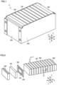
- Fig. 4 is a transverse cross sectional view of the battery module of Fig. 2 when viewed in a direction of arrow of a line IV-IV.
- Fig. 5 is a longitudinal cross sectional view of the battery module of Fig. 2 when viewed in a direction of arrow of a line V-V.
- separator 400 includes a foam 410 and an elastic body 420.
- Battery module 1 according to the present embodiment further includes an adhesive agent 430.
- Foam 410 is a portion of separator 400 that mainly receives pressing force caused by expansion of battery cell 100.
- Foam 410 is elastically deformable at least in the first direction (Y direction).
- Foam 410 according to the present embodiment is elastically deformable in any of the first to third directions.
- Foam 410 is in abutment with battery cells 100 in the Y direction.
- Foam 410 in the present embodiment is in abutment with each of battery cells 100 with adhesive agent 430 being interposed therebetween.
- Foam 410 is adhered to battery cell 100 by adhesive agent 430.
- Foam 410 is located substantially at the center of separator 400. Foam 410 is surrounded by elastic body 420 circumferentially with respect to the Y direction. Thus, foam 410 is accommodated in an inner space of elastic body 420. The position of foam 410 can be arbitrarily adjusted in the inner space of elastic body 420 by changing the position of foam 410 to be adhered to battery cell 100 using adhesive agent 430.
- Foam 410 can be composed of, for example, a material having electrical insulation property and elasticity, such as a silicone rubber, a urethane rubber, or an ethylene propylene rubber (EPDM).
- a material having electrical insulation property and elasticity such as a silicone rubber, a urethane rubber, or an ethylene propylene rubber (EPDM).
- Foam 410 has a base portion 411 and a plurality of bubble portions 412.
- Base portion 411 is a portion that forms an outer shape of foam 410.
- Base portion 411 is dotted with the plurality of bubble portions 412.
- Bubble portions 412 in the present embodiment have a continuous bubble structure.
- the plurality of bubble portions 412 communicate with each other. It should be noted that this continuous bubble structure is not shown in the figures in order to facilitate understanding of the invention. Further, not all the plurality of bubble portions 412 may necessarily communicate with each other.
- foam 410 functions as a heat insulation material in addition to mainly receiving pressing force caused by expansion of battery cell 100.
- Foam 410 has an excellent heat insulation property by utilizing heat conductivity of air in the inner space of bubble portions 412. Therefore, when battery cell 100 generates heat, transfer of the heat from adjacent foam 410 to a configuration therearound can be suppressed.
- Elastic body 420 is a frame body that surrounds foam 410 in a direction circumferential to the first direction (Y direction). It should be noted that elastic body 420 in the present embodiment is constituted of one member, but is not limited to this configuration. Elastic body 420 may be constituted of two or more members. When elastic body 420 is constituted of two or more members, the members are joined to each other by adhesion or the like.
- Elastic body 420 in the present embodiment is elastically deformable in any of the first to third directions. Elastic body 420 is elastically deformable by receiving pressing force caused by expansion of battery cell 100.
- Elastic body 420 is in abutment with battery cells 100 in the first direction (Y direction). Elastic body 420 in the present embodiment is adhered to each of the plurality of battery cells 100 through adhesive agent 430 and is in abutment with battery cell 100.
- Elastic body 420 can be composed of, for example, a material having electrical insulation property and elasticity, such as a silicone rubber, a fluororubber, a urethane rubber, a natural rubber, a styrene-butadiene rubber, a butyl rubber, an ethylene propylene rubber (EPM or EPDM), a butadiene rubber, an isoprene rubber, a norbomene rubber, or the like.
- a material having electrical insulation property and elasticity such as a silicone rubber, a fluororubber, a urethane rubber, a natural rubber, a styrene-butadiene rubber, a butyl rubber, an ethylene propylene rubber (EPM or EPDM), a butadiene rubber, an isoprene rubber, a norbomene rubber, or the like.
- Elastic body 420 according to the present embodiment is provided with a through hole 421 extending therethrough in the first direction (Y direction).
- Foam 410 is disposed inside through hole 421 with a clearance being interposed between foam 410 and elastic body 420.
- Elastic body 420 defines a closed space 10 in which foam 410 is accommodated.
- the expression "defines a closed space 10" includes: forming closed space 10 only by elastic body 420; and forming closed space 10 by elastic body 420 and another member.
- the other member may be battery cell 100 or another member having elasticity.
- foam 410 is surrounded by elastic body 420 circumferentially with respect to the first direction (Y direction), but may be surrounded by elastic body 420 in all the first to third directions.
- Closed space 10 is formed to be surrounded by two battery cells 100 of the plurality of battery cells 100 in the first direction (Y direction) and surrounded by elastic body 420 in the direction circumferential to the first direction (Y direction). Closed space 10 in the present embodiment is formed to be surrounded by the long side surfaces of battery cells 100 and elastic body 420 with the long side surfaces of battery cells 100 and elastic body 420 being adhered together by adhesive agent 430.
- Adhesive agent 430 may be provided on all the surfaces (both surfaces) at which foam 410 and elastic body 420 are in abutment with battery cells 100, or may be provided only on any surface (one surface) at which foam 410 and elastic body 420 are in abutment with battery cell 100.
- adhesive agent 430 may be provided on both surfaces of elastic body 420, and the adhesive agent may be provided on one surface of foam 410.
- adhesive agent 430 is provided on only one surface of each of foam 410 and elastic body 420, relative positioning thereof with respect to battery cell 100 is facilitated in assembling the battery module by providing adhesive agent 430 on the surfaces of foam 410 and elastic body 420 in the same direction.
- separator 400 When separator 400 is pressed by pressing force caused by expansion of battery cell 100 to elastically deform foam 410 and elastic body 420 in a compression direction in the first direction (Y direction), the volume of closed space 10 becomes smaller than that before they are elastically deformed.
- Fig. 6 is a longitudinal cross sectional view showing the configuration of the separator included in the battery module according to the first embodiment of the present technology before being assembled to the battery module.
- a product of an elastic modulus of elastic body 420 and a cross sectional area S2 of elastic body 420 in the first direction (Y direction) is smaller than a product of an elastic modulus of foam 410 and a cross sectional area S1 of foam 410 in the first direction (Y direction).
- elastic body 420 is more likely to be elastically deformed than foam 410.
- the elastic modulus of foam 410 is, for example, 1 MPa or more and 10 MPa or less.
- the elastic modulus is defined, for example, as follows.
- a test piece of the foam with a square shape having each side of 5 cm is used to obtain a load displacement curve (FS curve).
- FS curve load displacement curve
- the foam is fed with a pressure to 3.9 MPa at a pressure application rate of 30 N/min.
- the elastic modulus is calculated from the slope of the FS curve in such a range that the compression ratio of the foam is 1% to 20%.
- the applied pressure is released, which is followed by resting for 2 hours, and then the thickness of the foam is measured using a micrometer.
- a condition for the elastic modulus of foam 410 is such that a change in thickness of the foam after the test is 20% or less with respect to the thickness of the foam before the test.
- the elastic modulus of the elastic body can be also calculated in the same manner as described above.
- Cross sectional area S1 of foam 410 in the first direction (Y direction) is, for example, 65% or more and 120% or less of the cross sectional area of the electrode assembly in the first direction (Y direction). Since cross sectional area S1 of foam 410 in the first direction (Y direction) may be changed depending on the position of the cross section, it is desirable to use, for example, a cross sectional area with a minimum value from cross sectional areas calculated from a plurality of longitudinal cross sections of foam 410 when specifying the cross sectional area of foam 410.
- the elastic modulus of elastic body 420 is set so as to satisfy the above-described relation between the products of the elastic moduli and the cross sectional areas. That is, it is desirable to define the elastic modulus of foam 410, cross sectional area S1 of foam 410 in the first direction (Y direction), and cross sectional area S2 of elastic body 420 in the first direction (Y direction), and then define the elastic modulus of elastic body 420 so as to satisfy the above-described relation between the products of the elastic moduli and the cross sectional areas.
- Cross sectional area S2 of elastic body 420 in the first direction (Y direction) is, for example, 3% or more and 30% or less of the outer shape area of the case body when viewed in the first direction (Y direction). Since foam 410 serves as the portion that mainly receives pressing force caused by expansion of battery cell 100, cross sectional area S2 of elastic body 420 in the first direction (Y direction) is desirably smaller than a value obtained by dividing, by the elastic modulus of the elastic body, the product of cross sectional area S1 of foam 410 in the first direction (Y direction) and the elastic modulus of foam 410.
- Fig. 7 is a transverse cross sectional view showing the configuration of the separator included in the battery module according to the first embodiment of the present technology before being assembled to the battery module.
- a thickness T2 of elastic body 420 in the first direction (Y direction) is thicker than a thickness T1 of foam 410 in the first direction (Y direction).
- foam 410 is suppressed from being bulky in the inner space of elastic body 420, closed space 10 is readily secured when assembling separator 400 to battery module 1.
- Thickness T1 of foam 410 in the first direction (Y direction) is, for example, 3% or more and 17% or less with respect to the thickness of the battery cell in the first direction (Y direction).
- Thickness T2 of elastic body 420 in the first direction (Y direction) is, for example, 3% or more and 25% or less with respect to the thickness of the battery cell in the first direction (Y direction).
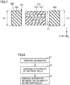
- FIG. 8 is a flowchart showing the method of manufacturing the battery module according to the first embodiment of the present technology. It should be noted that a method of assembling each of configurations other than battery cell 100 and separator 400 will not be described.
- separator 400 is prepared (step S1).
- a method of shaping separator 400 is not limited.
- the foam may be disposed in the inner space of the elastic body after being cut to a size with which the foam can be accommodated inside the elastic body, or the foam may be formed by disposing a below-described foaming agent in the inner space of the elastic body and foaming the foaming agent.
- the plurality of battery cells 100 are arranged in the first direction (Y direction) (step S2).
- the plurality of battery cells 100 are arranged in the first direction (Y direction) with a clearance being interposed therebetween.
- separator 400 is disposed between the plurality of battery cells 100 (step S3). Specifically, separator 400 including foam 410 elastically deformable at least in the first direction (Y direction) and elastic body 420 defining closed space 10 in which foam 410 is accommodated is disposed between the plurality of battery cells 100. In the present embodiment, separator 400 is adhered to battery cell 100 by adhesive agent 430.
- Fig. 9 is a transverse cross sectional view showing a configuration of a separator when a battery cell is expanded in the battery module according to the comparative example.
- a battery module 9 includes battery cells 100 and a separator 900.
- Separator 900 includes a first member 910 and a second member 920.
- First member 910 is a foam elastically deformable in the first direction (Y direction) by pressing force caused by expansion of battery cell 100.
- Second member 920 is a member having a strength such that substantially no elastic deformation is caused by pressing force caused by expansion of battery cell 100.
- First member 910 has a base portion 911 and bubble portions 912. Bubble portions 912 have a continuous bubble structure. Each of bubble portions 912 receives pressing force caused by expansion of battery cell 100 to compress an inner space thereof, thus resulting in a high pressure therein.
- Second member 920 defines a closed space 90 in which first member 910 is accommodated. Second member 920 is not deformed by pressing force from battery cell 100. Therefore, the volume of closed space 90 is less likely to become smaller than that before receiving the pressing force from battery cell 100. Thus, the pressure of closed space 90 is lower than the pressure of the inner space of bubble portion 912. Since bubble portions 912 having the continuous bubble structure communicate with closed space 90, the pressure of the inner space of each bubble portion 912 is released to closed space 90 on the low pressure side in order to maintain the equilibrium state.
- separator 400 as shown in Figs. 4 and 5 , each of foam 410 and elastic body 420 is elastically deformed in response to receiving the pressing force from battery cell 100. Therefore, in response to the expansion of battery cell 100, the volume of closed space 10 becomes smaller than that before receiving the pressing force from battery cell 100.
- the pressure inside closed space 10 becomes higher. Specifically, the pressure inside closed space 10 becomes comparable to the pressure of the inner space of each bubble portion 412 in foam 410.
- Bubble portions 412 having the continuous bubble structure communicate with closed space 10, but a pressure difference between closed space 10 and the inner space of each bubble portion 412 is smaller than that in the comparative example, with the result that the pressure of the inner space of bubble portion 412 is suppressed from being released to closed space 10.
- the pressure of the inner space of bubble portion 412 is suppressed from being decreased, thereby suppressing decreased reaction force of foam 410 against the expansion of battery cell 100. This leads to suppression of decreased reaction force of separator 400.
- closed space 10 is formed to be surrounded by two battery cells 100 of the plurality of battery cells 100 in the first direction (Y direction) and surrounded by elastic body 420 in the direction circumferential to the first direction (Y direction).
- foam 410 can be readily inserted into elastic body 420 via through hole 421.
- the product of the elastic modulus of elastic body 420 and cross sectional area S2 of elastic body 420 in the first direction (Y direction) is smaller than the product of the elastic modulus of foam 410 and cross sectional area S1 of foam 410 in the first direction (Y direction), with the result that elastic body 420 can be more likely to be elastically deformed than foam 410.
- closed space 10 formed by elastic body 420 can be compressed and closed readily.
- the following describes a battery module and a method of manufacturing the battery module according to a second embodiment of the present technology. Since the battery module and the method of manufacturing the battery module according to the second embodiment of the present technology are different from battery module 1 and the method of manufacturing battery module 1 according to the first embodiment of the present technology in terms of the configuration of the separator and the method of manufacturing the foam, the same configurations as those in battery module 1 and the method of manufacturing battery module 1 according to the first embodiment of the present technology will not be described repeatedly.
- Fig. 10 is a longitudinal cross sectional view showing the configuration of the separator included in the battery module according to the second embodiment of the present technology.
- Fig. 11 is a transverse cross sectional view of the separator of Fig. 10 when viewed in a direction of arrow of a line XI-XI.
- the battery module according to the second embodiment of the present technology includes battery cells, end plates, restraint members, and a separator 400B.
- Separator 400B includes foams 410B and an elastic body 420B.
- Elastic body 420B has a main body portion 421B.
- Main body portion 421B is provided with a plurality of recesses 422B.
- Foams 410B are disposed inside the plurality of recesses 422B. It should be noted that one recess 422B may be provided.
- Each of the plurality of recesses 422B are opened in the first direction (Y direction) to form a closed space 10B.
- Closed space 10B is formed in such a manner that five of six sides of the space are surrounded by recess 422B and the remaining one side is surrounded by the long side surface of the battery cell.
- Fig. 12 is a transverse cross sectional view showing a state in which the foam is formed from a foaming agent in the battery module according to the second embodiment of the present technology.
- foaming agents 20 are disposed in elastic body 420B. Specifically, foaming agents 20 are disposed inside the plurality of recesses 422B.
- Foaming agent 20 yet to be foamed and disposed in each recess 422B is foamed to form foam 410B.
- foam 410B is disposed in recess 422B of elastic body 420B.
- the foam formed by the foaming of foaming agent 20 is in close contact with recess 422B.
- the plurality of recesses 422B are disposed, but one recess 422B may be disposed. In this case, an occupation ratio of recess 422B is desirably higher than that of the main body portion in order to secure a heat insulation property readily.
- the reaction force of foam 410B can be suppressed from being decreased.
- the reaction force of separator 400B can be suppressed from being decreased after foam 410B is elastically deformed in the compression direction.
- closed space 10B having high hermeticity can be formed as compared with the case where the closed space is formed by providing a through hole in the elastic body.
- foaming agent 20 disposed inside elastic body 420B is foamed to form foam 410B
- a shaping step such as cutting of foam 410B can be omitted, thereby efficiently manufacturing separator 400B in which foam 410B is disposed in the inner space of elastic body 420B.
- the disposing of foam 410B is completed with excellent positional precision at the time of foaming to form foam 410B inside recess 422B located at a determined position of elastic body 420B. That is, an assembling process of disposing it can be omitted.
Landscapes
- Chemical & Material Sciences (AREA)
- Chemical Kinetics & Catalysis (AREA)
- Electrochemistry (AREA)
- General Chemical & Material Sciences (AREA)
- Engineering & Computer Science (AREA)
- Manufacturing & Machinery (AREA)
- Battery Mounting, Suspending (AREA)
Abstract
A battery module includes a plurality of battery cells (100) and a separator (400). The plurality of battery cells (100) are arranged in a first direction. The separator (400) is disposed between the plurality of battery cells (100). The separator (400) includes a foam (410) and an elastic body (420). The foam (410) is elastically deformable at least in the first direction. The elastic body (420) defines a closed space (10) in which the foam (410) is accommodated.
Description
- This nonprovisional application is based on
Japanese Patent Application No. 2023-012613 filed on January 31, 2023 - The present technology relates to a battery module and a method of manufacturing the battery module.
-
WO 2019/142645 is a prior art document that discloses a configuration of a power storage device. The power storage device described inWO 2019/142645 includes a secondary battery and a cushioning plate. The cushioning plate is in abutment with each of opposing side walls of the secondary battery. The cushioning plate includes a non-deformable portion and a deformable portion. The non-deformable portion is a portion that is not substantially deformed in response to a change in volume of the secondary battery. The non-deformable portion holds the secondary battery. The non-deformable portion is provided with a through hole or recess into which the deformable portion is fitted. The deformable portion is a portion that is elastically deformed in response to a change in volume of the secondary battery. The deformable portion absorbs the change in volume of the secondary battery. - For improvement of a temperature characteristic of a separator disposed between a plurality of battery cells or the like, a foam may be used for a configuration of the separator. When the foam is elastically deformed in a compression direction due to expansion or the like of each of the plurality of battery cells, an increased pressure in a bubble portion inside the foam may be released to surroundings of the foam via the bubble portion. Thus, reaction force of the foam is decreased, with the result that reaction force of the separator may be decreased after the foam is elastically deformed in the compression direction.
- The present technology has been made to solve the above-described problem and has an object to provide a battery module and a method of manufacturing the battery module so as to suppress a decrease in reaction force of a separator after a foam is elastically deformed in a compression direction.
- The present technology provides the following battery module.
- [1] A battery module comprising:
- a plurality of battery cells arranged in a first direction; and
- a separator disposed between the plurality of battery cells, wherein
- the separator includes
- a foam elastically deformable at least in the first direction, and
- an elastic body that defines a closed space in which the foam is accommodated.
- [2] The battery module according to [1], wherein the closed space is formed to be surrounded by two battery cells of the plurality of battery cells in the first direction and surrounded by the elastic body in a direction circumferential to the first direction.
- [3] The battery module according to [1] or [2], wherein in a state in which the separator is detached from the battery module, a thickness of the elastic body in the first direction is thicker than a thickness of the foam in the first direction.
- [4] The battery module according to [2] or [3], wherein in a state in which the separator is detached from the battery module, a product of an elastic modulus of the elastic body and a cross sectional area of the elastic body in the first direction is smaller than a product of an elastic modulus of the foam and a cross sectional area of the foam in the first direction.
- [5] The battery module according to any one of [2] to [4], wherein the elastic body is adhered to the plurality of battery cells through an adhesive agent.
- [6] The battery module according to any one of [1] to [5], wherein
- the elastic body has a main body portion provided with a recess that is opened in the first direction and that forms the closed space, and
- the foam is disposed inside the recess.
- [7] A method of manufacturing a battery module, the method comprising:
- arranging a plurality of battery cells in a first direction; and
- disposing a separator between the plurality of battery cells, the separator including a foam elastically deformable at least in the first direction and an elastic body that defines a closed space in which the foam is accommodated.
- [8] The method of manufacturing the battery module according to [7], further comprising preparing the separator, wherein
- the preparing of the separator includes disposing a foaming agent in the elastic body and foaming the foaming agent to form the foam, the disposing of the foaming agent in the elastic body includes disposing the foaming agent in a recess that is formed in the elastic body and that is opened in the first direction, and
- the foaming of the foaming agent includes foaming the foaming agent disposed in the recess.
- The foregoing and other objects, features, aspects and advantages of the present invention will become more apparent from the following detailed description of the present invention when taken in conjunction with the accompanying drawings.
-
-
Fig. 1 is a perspective view showing a configuration of a battery module according to a first embodiment of the present technology. -
Fig. 2 is a perspective view showing an internal configuration of the battery module according to the first embodiment of the present technology. -
Fig. 3 is a perspective view showing a configuration of each battery cell included in the battery module according to the first embodiment of the present technology. -
Fig. 4 is a transverse cross sectional view of the battery module ofFig. 2 when viewed in a direction of arrow of a line IV-IV. -
Fig. 5 is a longitudinal cross sectional view of the battery module ofFig. 2 when viewed in a direction of arrow of a line V-V. -
Fig. 6 is a longitudinal cross sectional view showing a configuration of a separator included in the battery module according to the first embodiment of the present technology before being assembled to the battery module. -
Fig. 7 is a transverse cross sectional view showing the configuration of the separator included in the battery module according to the first embodiment of the present technology before being assembled to the battery module. -
Fig. 8 is a flowchart showing a method of manufacturing the battery module according to the first embodiment of the present technology. -
Fig. 9 is a transverse cross sectional view showing a configuration of a separator when a battery cell is expanded in a battery module according to a comparative example. -
Fig. 10 is a longitudinal cross sectional view showing a configuration of a separator included in a battery module according to a second embodiment of the present technology. -
Fig. 11 is a transverse cross sectional view of the separator ofFig. 10 when viewed in a direction of arrow of a line XI-XI. -
Fig. 12 is a transverse cross sectional view showing a state in which a foam is formed from a foaming agent in the battery module according to the second embodiment of the present technology. - Hereinafter, embodiments of the present technology will be described. It should be noted that the same or corresponding portions are denoted by the same reference characters, and may not be described repeatedly.
- It should be noted that in the embodiments described below, when reference is made to number, amount, and the like, the scope of the present technology is not necessarily limited to the number, amount, and the like unless otherwise stated particularly. Further, in the embodiments described below, each component is not necessarily essential to the present technology unless otherwise stated particularly. Further, the present technology is not limited to one that necessarily exhibits all the functions and effects stated in the present embodiment.
- It should be noted that in the present specification, the terms "comprise", "include", and "have" are open-end terms. That is, when a certain configuration is included, a configuration other than the foregoing configuration may or may not be included.
- Also, in the present specification, when geometric terms and terms representing positional/directional relations are used, for example, when terms such as "parallel", "orthogonal", "obliquely at 45°", "coaxial", and "along" are used, these terms permit manufacturing errors or slight fluctuations. In the present specification, when terms representing relative positional relations such as "upper side" and "lower side" are used, each of these terms is used to indicate a relative positional relation in one state, and the relative positional relation may be reversed or turned at any angle in accordance with an installation direction of each mechanism (for example, the entire mechanism is reversed upside down).
- In the present specification, the term "battery" is not limited to a lithium ion battery, and may include other batteries such as a nickel-metal hydride battery and a sodium ion battery. In the present specification, the term "electrode" may collectively represent a positive electrode and a negative electrode.
- Further, the "battery module" can be mounted on vehicles such as a hybrid electric vehicle (HEV), a plug-in hybrid electric vehicle (PHEV), and a battery electric vehicle (BEV). It should be noted that the use of the "battery module" is not limited to the use in a vehicle.
- It should be noted that in each of the figures, an X direction serving as a second direction is defined as a direction in which a positive electrode terminal and a negative electrode terminal of a battery cell are arranged, a Y direction serving as a first direction is defined as a direction in which a plurality of battery cells are arranged, and a Z direction serving as a third direction is defined as a height direction of the battery module. A cross sectional view of the battery module when viewed in the Y direction will be referred to as a longitudinal cross sectional view, and a cross sectional view of the battery module when viewed in the Z direction will be referred to as a transverse cross sectional view. Further, in order to facilitate understanding of the invention, the size of each configuration in the figures may be changed from the actual size thereof.
- First, a configuration of a battery module according to a first embodiment of the present technology will be described.
Fig. 1 is a perspective view showing a configuration of the battery module according to the first embodiment of the present technology.Fig. 2 is a perspective view showing an internal configuration of the battery module according to the first embodiment of the present technology. - As shown in
Figs. 1 and 2 , abattery module 1 according to the first embodiment of the present technology includesbattery cells 100,end plates 200,restraint members 300, andseparators 400. - The plurality of
battery cells 100 are arranged side by side in the first direction (Y direction). Eachseparator 400 described below is interposed betweenbattery cells 100. The plurality ofbattery cells 100, which are sandwiched between twoend plates 200, are pressed byend plates 200, and are therefore restrained between twoend plates 200. -
End plates 200 are provided at both ends of the plurality ofbattery cells 100 in the first direction (Y direction). Each ofend plates 200 is fixed to a base such as a housing that accommodatesbattery module 1.End plate 200 is composed of, for example, aluminum or iron. - As shown in
Fig. 1 ,restraint members 300 are provided at both ends of the plurality ofbattery cells 100 andend plates 200 in the X direction. When each ofrestraint members 300 is engaged withend plates 200 with compressive force in the Y direction being applied to the plurality of stackedbattery cells 100 andend plates 200 and then the compressive force is released, tensile force acts onrestraint member 300 that connects twoend plates 200. As a reaction thereto,restraint member 300 presses twoend plates 200 in directions of bringing them closer to each other. As a result,restraint member 300 restrains the plurality ofbattery cells 100 in the Y direction. -
Separator 400 is disposed between the plurality ofbattery cells 100.Separator 400 is in abutment with long side surfaces of the plurality ofbattery cells 100.Separator 400 has an insulation property. Thus,separator 400 insulates the plurality ofbattery cells 100 from each other. Details ofseparator 400 will be described later. -
Fig. 3 is a perspective view showing a configuration of each battery cell included in the battery module according to the first embodiment of the present technology. - As shown in
Fig. 3 ,battery cell 100 includeselectrode terminals 110, acase body 120, a gas-discharge valve 130, and anelectrode assembly 140. -
Electrode terminals 110 have apositive electrode terminal 111 and anegative electrode terminal 112.Electrode terminals 110 are formed oncase body 120. -
Case body 120 is a container that accommodateselectrode assembly 140 and an electrolyte solution.Case body 120 has a substantially rectangular parallelepiped shape.Case body 120 is composed of aluminum, an aluminum alloy, iron, an iron alloy, or the like. -
Case body 120 has anupper surface 121, alower surface 122, a pair of long side surfaces 123, and a pair of short side surfaces 124. -
Electrode terminals 110 are disposed onupper surface 121.Lower surface 122 is opposite toupper surface 121 in the third direction (Z direction). - The pair of long side surfaces 123 and the pair of short side surfaces 124 constitute side surfaces of
case body 120. The pair of long side surfaces 123 and the pair of short side surfaces 124 serving as the side surfaces ofcase body 120 intersect each ofupper surface 121 andlower surface 122. The pair of long side surfaces 123 are opposite to each other in the first direction (Y direction) withelectrode assembly 140 being interposed therebetween. The pair of short side surfaces 124 are opposite to each other in the second direction (X direction) withelectrode assembly 140 being interposed therebetween. Each of the pair of long side surfaces 123 has a larger area than that of each of the pair of short side surfaces 124. - Gas-
discharge valve 130 is fractured when pressure insidecase body 120 becomes equal to or more than a predetermined value. Thus, gas incase body 120 is discharged to outside ofcase body 120. -
Electrode assembly 140 functions as a power generation element.Electrode assembly 140 includes a positive electrode and a negative electrode (not shown). A substrate of the positive electrode is, for example, an aluminum alloy foil. A substrate of the negative electrode is, for example, a copper alloy foil.Electrode assembly 140 is, for example, a wound type electrode assembly in which the positive electrode and the negative electrode are wound or a stacked type electrode assembly in which the positive electrode and the negative electrode are alternately stacked. -
Fig. 4 is a transverse cross sectional view of the battery module ofFig. 2 when viewed in a direction of arrow of a line IV-IV.Fig. 5 is a longitudinal cross sectional view of the battery module ofFig. 2 when viewed in a direction of arrow of a line V-V. - As shown in
Figs. 4 and5 ,separator 400 according to the present embodiment includes afoam 410 and anelastic body 420.Battery module 1 according to the present embodiment further includes anadhesive agent 430. -
Foam 410 is a portion ofseparator 400 that mainly receives pressing force caused by expansion ofbattery cell 100.Foam 410 is elastically deformable at least in the first direction (Y direction).Foam 410 according to the present embodiment is elastically deformable in any of the first to third directions. -
Foam 410 is in abutment withbattery cells 100 in the Y direction.Foam 410 in the present embodiment is in abutment with each ofbattery cells 100 withadhesive agent 430 being interposed therebetween.Foam 410 is adhered tobattery cell 100 byadhesive agent 430. -
Foam 410 is located substantially at the center ofseparator 400.Foam 410 is surrounded byelastic body 420 circumferentially with respect to the Y direction. Thus,foam 410 is accommodated in an inner space ofelastic body 420. The position offoam 410 can be arbitrarily adjusted in the inner space ofelastic body 420 by changing the position offoam 410 to be adhered tobattery cell 100 usingadhesive agent 430. -
Foam 410 can be composed of, for example, a material having electrical insulation property and elasticity, such as a silicone rubber, a urethane rubber, or an ethylene propylene rubber (EPDM). -
Foam 410 has abase portion 411 and a plurality ofbubble portions 412.Base portion 411 is a portion that forms an outer shape offoam 410. -
Base portion 411 is dotted with the plurality ofbubble portions 412.Bubble portions 412 in the present embodiment have a continuous bubble structure. Thus, the plurality ofbubble portions 412 communicate with each other. It should be noted that this continuous bubble structure is not shown in the figures in order to facilitate understanding of the invention. Further, not all the plurality ofbubble portions 412 may necessarily communicate with each other. - It should be noted that
foam 410 functions as a heat insulation material in addition to mainly receiving pressing force caused by expansion ofbattery cell 100.Foam 410 has an excellent heat insulation property by utilizing heat conductivity of air in the inner space ofbubble portions 412. Therefore, whenbattery cell 100 generates heat, transfer of the heat fromadjacent foam 410 to a configuration therearound can be suppressed. -
Elastic body 420 is a frame body that surroundsfoam 410 in a direction circumferential to the first direction (Y direction). It should be noted thatelastic body 420 in the present embodiment is constituted of one member, but is not limited to this configuration.Elastic body 420 may be constituted of two or more members. Whenelastic body 420 is constituted of two or more members, the members are joined to each other by adhesion or the like. -
Elastic body 420 in the present embodiment is elastically deformable in any of the first to third directions.Elastic body 420 is elastically deformable by receiving pressing force caused by expansion ofbattery cell 100. -
Elastic body 420 is in abutment withbattery cells 100 in the first direction (Y direction).Elastic body 420 in the present embodiment is adhered to each of the plurality ofbattery cells 100 throughadhesive agent 430 and is in abutment withbattery cell 100. -
Elastic body 420 can be composed of, for example, a material having electrical insulation property and elasticity, such as a silicone rubber, a fluororubber, a urethane rubber, a natural rubber, a styrene-butadiene rubber, a butyl rubber, an ethylene propylene rubber (EPM or EPDM), a butadiene rubber, an isoprene rubber, a norbomene rubber, or the like. -
Elastic body 420 according to the present embodiment is provided with a throughhole 421 extending therethrough in the first direction (Y direction).Foam 410 is disposed inside throughhole 421 with a clearance being interposed betweenfoam 410 andelastic body 420. -
Elastic body 420 defines aclosed space 10 in which foam 410 is accommodated. The expression "defines aclosed space 10" includes: formingclosed space 10 only byelastic body 420; and formingclosed space 10 byelastic body 420 and another member. The other member may bebattery cell 100 or another member having elasticity. Further,foam 410 is surrounded byelastic body 420 circumferentially with respect to the first direction (Y direction), but may be surrounded byelastic body 420 in all the first to third directions. -
Closed space 10 is formed to be surrounded by twobattery cells 100 of the plurality ofbattery cells 100 in the first direction (Y direction) and surrounded byelastic body 420 in the direction circumferential to the first direction (Y direction).Closed space 10 in the present embodiment is formed to be surrounded by the long side surfaces ofbattery cells 100 andelastic body 420 with the long side surfaces ofbattery cells 100 andelastic body 420 being adhered together byadhesive agent 430.Adhesive agent 430 may be provided on all the surfaces (both surfaces) at whichfoam 410 andelastic body 420 are in abutment withbattery cells 100, or may be provided only on any surface (one surface) at whichfoam 410 andelastic body 420 are in abutment withbattery cell 100. Further, for example,adhesive agent 430 may be provided on both surfaces ofelastic body 420, and the adhesive agent may be provided on one surface offoam 410. Whenadhesive agent 430 is provided on only one surface of each offoam 410 andelastic body 420, relative positioning thereof with respect tobattery cell 100 is facilitated in assembling the battery module by providingadhesive agent 430 on the surfaces offoam 410 andelastic body 420 in the same direction. - When
separator 400 is pressed by pressing force caused by expansion ofbattery cell 100 to elastically deformfoam 410 andelastic body 420 in a compression direction in the first direction (Y direction), the volume ofclosed space 10 becomes smaller than that before they are elastically deformed. -
Fig. 6 is a longitudinal cross sectional view showing the configuration of the separator included in the battery module according to the first embodiment of the present technology before being assembled to the battery module. - As shown in
Fig. 6 , in a state in which separator 400 is detached from the battery module, a product of an elastic modulus ofelastic body 420 and a cross sectional area S2 ofelastic body 420 in the first direction (Y direction) is smaller than a product of an elastic modulus offoam 410 and a cross sectional area S1 offoam 410 in the first direction (Y direction). With this relation between the products of the elastic moduli and the cross sectional areas,elastic body 420 is more likely to be elastically deformed thanfoam 410. - The elastic modulus of
foam 410 is, for example, 1 MPa or more and 10 MPa or less. The elastic modulus is defined, for example, as follows. A test piece of the foam with a square shape having each side of 5 cm is used to obtain a load displacement curve (FS curve). As a test condition, the foam is fed with a pressure to 3.9 MPa at a pressure application rate of 30 N/min. The elastic modulus is calculated from the slope of the FS curve in such a range that the compression ratio of the foam is 1% to 20%. After the test described above, the applied pressure is released, which is followed by resting for 2 hours, and then the thickness of the foam is measured using a micrometer. A condition for the elastic modulus offoam 410 is such that a change in thickness of the foam after the test is 20% or less with respect to the thickness of the foam before the test. The elastic modulus of the elastic body can be also calculated in the same manner as described above. - Cross sectional area S1 of
foam 410 in the first direction (Y direction) is, for example, 65% or more and 120% or less of the cross sectional area of the electrode assembly in the first direction (Y direction). Since cross sectional area S1 offoam 410 in the first direction (Y direction) may be changed depending on the position of the cross section, it is desirable to use, for example, a cross sectional area with a minimum value from cross sectional areas calculated from a plurality of longitudinal cross sections offoam 410 when specifying the cross sectional area offoam 410. - The elastic modulus of
elastic body 420 is set so as to satisfy the above-described relation between the products of the elastic moduli and the cross sectional areas. That is, it is desirable to define the elastic modulus offoam 410, cross sectional area S1 offoam 410 in the first direction (Y direction), and cross sectional area S2 ofelastic body 420 in the first direction (Y direction), and then define the elastic modulus ofelastic body 420 so as to satisfy the above-described relation between the products of the elastic moduli and the cross sectional areas. - Cross sectional area S2 of
elastic body 420 in the first direction (Y direction) is, for example, 3% or more and 30% or less of the outer shape area of the case body when viewed in the first direction (Y direction). Sincefoam 410 serves as the portion that mainly receives pressing force caused by expansion ofbattery cell 100, cross sectional area S2 ofelastic body 420 in the first direction (Y direction) is desirably smaller than a value obtained by dividing, by the elastic modulus of the elastic body, the product of cross sectional area S1 offoam 410 in the first direction (Y direction) and the elastic modulus offoam 410. -
Fig. 7 is a transverse cross sectional view showing the configuration of the separator included in the battery module according to the first embodiment of the present technology before being assembled to the battery module. - As shown in
Fig. 7 , in a state in which separator 400 is detached from the battery module, a thickness T2 ofelastic body 420 in the first direction (Y direction) is thicker than a thickness T1 offoam 410 in the first direction (Y direction). Thus, sincefoam 410 is suppressed from being bulky in the inner space ofelastic body 420,closed space 10 is readily secured when assemblingseparator 400 tobattery module 1. - Thickness T1 of
foam 410 in the first direction (Y direction) is, for example, 3% or more and 17% or less with respect to the thickness of the battery cell in the first direction (Y direction). Thickness T2 ofelastic body 420 in the first direction (Y direction) is, for example, 3% or more and 25% or less with respect to the thickness of the battery cell in the first direction (Y direction). - Next, a method of manufacturing
battery module 1 according to the first embodiment of the present technology will be described.Fig. 8 is a flowchart showing the method of manufacturing the battery module according to the first embodiment of the present technology. It should be noted that a method of assembling each of configurations other thanbattery cell 100 andseparator 400 will not be described. - As shown in
Fig. 8 , in the method of manufacturingbattery module 1 according to the first embodiment of the present technology, first,separator 400 is prepared (step S1). A method of shapingseparator 400 is not limited. Inseparator 400, the foam may be disposed in the inner space of the elastic body after being cut to a size with which the foam can be accommodated inside the elastic body, or the foam may be formed by disposing a below-described foaming agent in the inner space of the elastic body and foaming the foaming agent. - Next, the plurality of
battery cells 100 are arranged in the first direction (Y direction) (step S2). The plurality ofbattery cells 100 are arranged in the first direction (Y direction) with a clearance being interposed therebetween. - Next,
separator 400 is disposed between the plurality of battery cells 100 (step S3). Specifically,separator 400 includingfoam 410 elastically deformable at least in the first direction (Y direction) andelastic body 420 definingclosed space 10 in which foam 410 is accommodated is disposed between the plurality ofbattery cells 100. In the present embodiment,separator 400 is adhered tobattery cell 100 byadhesive agent 430. - Here, a configuration of a battery module according to a comparative example will be described.
Fig. 9 is a transverse cross sectional view showing a configuration of a separator when a battery cell is expanded in the battery module according to the comparative example. - As shown in
Fig. 9 , abattery module 9 according to the comparative example includesbattery cells 100 and aseparator 900.Separator 900 includes afirst member 910 and asecond member 920. -
First member 910 is a foam elastically deformable in the first direction (Y direction) by pressing force caused by expansion ofbattery cell 100.Second member 920 is a member having a strength such that substantially no elastic deformation is caused by pressing force caused by expansion ofbattery cell 100. -
First member 910 has abase portion 911 andbubble portions 912.Bubble portions 912 have a continuous bubble structure. Each ofbubble portions 912 receives pressing force caused by expansion ofbattery cell 100 to compress an inner space thereof, thus resulting in a high pressure therein. -
Second member 920 defines aclosed space 90 in whichfirst member 910 is accommodated.Second member 920 is not deformed by pressing force frombattery cell 100. Therefore, the volume ofclosed space 90 is less likely to become smaller than that before receiving the pressing force frombattery cell 100. Thus, the pressure ofclosed space 90 is lower than the pressure of the inner space ofbubble portion 912. Sincebubble portions 912 having the continuous bubble structure communicate withclosed space 90, the pressure of the inner space of eachbubble portion 912 is released toclosed space 90 on the low pressure side in order to maintain the equilibrium state. - In a state in which
first member 910 is compressed by receiving the pressing force frombattery cell 100, the pressure of the inner space ofbubble portion 912 is released to closed space 90 (in directions of arrows inFig. 9 ), thereby decreasing the pressure of the inner space ofbubble portion 912. Thus, reaction force offirst member 910 against the expansion ofbattery cell 100 is decreased. This leads to decreased reaction force ofseparator 900. - On the other hand, in
separator 400 according to the present embodiment, as shown inFigs. 4 and5 , each offoam 410 andelastic body 420 is elastically deformed in response to receiving the pressing force frombattery cell 100. Therefore, in response to the expansion ofbattery cell 100, the volume ofclosed space 10 becomes smaller than that before receiving the pressing force frombattery cell 100. - As the volume of
closed space 10 becomes smaller, the pressure insideclosed space 10 becomes higher. Specifically, the pressure insideclosed space 10 becomes comparable to the pressure of the inner space of eachbubble portion 412 infoam 410.Bubble portions 412 having the continuous bubble structure communicate withclosed space 10, but a pressure difference betweenclosed space 10 and the inner space of eachbubble portion 412 is smaller than that in the comparative example, with the result that the pressure of the inner space ofbubble portion 412 is suppressed from being released toclosed space 10. Thus, the pressure of the inner space ofbubble portion 412 is suppressed from being decreased, thereby suppressing decreased reaction force offoam 410 against the expansion ofbattery cell 100. This leads to suppression of decreased reaction force ofseparator 400. - In each of
battery module 1 and the method of manufacturingbattery module 1 according to the first embodiment of the present technology, whenfoam 410 andelastic body 420 ofseparator 400 are elastically deformed in the compression direction due toseparator 400 receiving pressing force caused by expansion ofbattery cell 100, the inside offoam 410 andclosed space 10 aroundfoam 410 can be compressed to increase the pressure becausefoam 410 is accommodated inclosed space 10 formed byelastic body 420. Therefore, even when the pressure of the inner space offoam 410 is increased in response to the elastic deformation offoam 410 in the compression direction, the pressure is suppressed from being released toclosed space 10 aroundfoam 410, thereby suppressing decreased reaction force offoam 410. Thus, a decrease in the reaction force ofseparator 400 afterfoam 410 is elastically deformed in the compression direction can be suppressed. - In each of
battery module 1 and the method of manufacturingbattery module 1 according to the first embodiment of the present technology, sincefoam 410 is used inseparator 400 and the inner space is provided inelastic body 420, the heat conductivity ofseparator 400 can be made low by utilizing the heat conductivity of air, with the result that the reaction force ofseparator 400 can be suppressed from being decreased in response to an increased temperature ofseparator 400 due to the use ofbattery module 1 as compared with a case where an elastic body having no bubble portion is used for a whole of the separator. - In
battery module 1 according to the first embodiment of the present technology,closed space 10 is formed to be surrounded by twobattery cells 100 of the plurality ofbattery cells 100 in the first direction (Y direction) and surrounded byelastic body 420 in the direction circumferential to the first direction (Y direction). Thus, when disposingfoam 410 insideelastic body 420,foam 410 can be readily inserted intoelastic body 420 via throughhole 421. - In
battery module 1 according to the first embodiment of the present technology, since thickness T2 ofelastic body 420 is thicker than thickness T1 of the foam,foam 410 is not bulky in the inner space of throughhole 421 ofelastic body 420, with the result that closedspace 10 can be readily secured. - In
battery module 1 according to the first embodiment of the present technology, in the state in which separator 400 is detached frombattery module 1, the product of the elastic modulus ofelastic body 420 and cross sectional area S2 ofelastic body 420 in the first direction (Y direction) is smaller than the product of the elastic modulus offoam 410 and cross sectional area S1 offoam 410 in the first direction (Y direction), with the result thatelastic body 420 can be more likely to be elastically deformed thanfoam 410. Thus,closed space 10 formed byelastic body 420 can be compressed and closed readily. - In
battery module 1 according to the first embodiment of the present technology, sinceelastic body 420 is adhered tobattery cell 100 throughadhesive agent 430, air is less likely to leak from betweenelastic body 420 and the long side surface ofbattery cell 100. This is because it is possible to preventelastic body 420 from being expanded due to the internal pressure ofclosed space 10 and being deviated fromlong side surface 123 ofbattery cell 100 to decrease the pressure. As a result, the closed state and high-pressure state ofclosed space 10 can be readily secured. Further, by adheringfoam 410 usingadhesive agent 430, positioning can be facilitated during assembling. - The following describes a battery module and a method of manufacturing the battery module according to a second embodiment of the present technology. Since the battery module and the method of manufacturing the battery module according to the second embodiment of the present technology are different from
battery module 1 and the method of manufacturingbattery module 1 according to the first embodiment of the present technology in terms of the configuration of the separator and the method of manufacturing the foam, the same configurations as those inbattery module 1 and the method of manufacturingbattery module 1 according to the first embodiment of the present technology will not be described repeatedly. -
Fig. 10 is a longitudinal cross sectional view showing the configuration of the separator included in the battery module according to the second embodiment of the present technology.Fig. 11 is a transverse cross sectional view of the separator ofFig. 10 when viewed in a direction of arrow of a line XI-XI. - As shown in
Figs. 10 and11 , the battery module according to the second embodiment of the present technology includes battery cells, end plates, restraint members, and aseparator 400B.Separator 400B includesfoams 410B and anelastic body 420B. -
Elastic body 420B has amain body portion 421B.Main body portion 421B is provided with a plurality ofrecesses 422B.Foams 410B are disposed inside the plurality ofrecesses 422B. It should be noted that onerecess 422B may be provided. - Each of the plurality of
recesses 422B are opened in the first direction (Y direction) to form aclosed space 10B.Closed space 10B is formed in such a manner that five of six sides of the space are surrounded byrecess 422B and the remaining one side is surrounded by the long side surface of the battery cell. -
Fig. 12 is a transverse cross sectional view showing a state in which the foam is formed from a foaming agent in the battery module according to the second embodiment of the present technology. - As shown in
Fig. 12 , in a step of preparingseparator 400B of the battery module according to the second embodiment of the present technology, foamingagents 20 are disposed inelastic body 420B. Specifically, foamingagents 20 are disposed inside the plurality ofrecesses 422B. -
Foaming agent 20 yet to be foamed and disposed in eachrecess 422B is foamed to formfoam 410B. Thus,foam 410B is disposed inrecess 422B ofelastic body 420B. The foam formed by the foaming of foamingagent 20 is in close contact withrecess 422B. It should be noted that the plurality ofrecesses 422B are disposed, but onerecess 422B may be disposed. In this case, an occupation ratio ofrecess 422B is desirably higher than that of the main body portion in order to secure a heat insulation property readily. - In each of the battery module and the method of manufacturing the battery module according to the second embodiment of the present technology, as with the first embodiment, the reaction force of
foam 410B can be suppressed from being decreased. Thus, the reaction force ofseparator 400B can be suppressed from being decreased afterfoam 410B is elastically deformed in the compression direction. - In the battery module according to the second embodiment of the present technology, since the five sides of the six sides of
closed space 10B can be surrounded byelastic body 420B,closed space 10B having high hermeticity can be formed as compared with the case where the closed space is formed by providing a through hole in the elastic body. - In the method of manufacturing the battery module according to the second embodiment of the present technology, since foaming
agent 20 disposed insideelastic body 420B is foamed to formfoam 410B, a shaping step such as cutting offoam 410B can be omitted, thereby efficiently manufacturingseparator 400B in which foam 410B is disposed in the inner space ofelastic body 420B. This is because the disposing offoam 410B is completed with excellent positional precision at the time of foaming to formfoam 410B insiderecess 422B located at a determined position ofelastic body 420B. That is, an assembling process of disposing it can be omitted. - Although the embodiments of the present invention have been described and illustrated in detail, it is clearly understood that the same is by way of illustration and example only and is not to be taken by way of limitation. The scope of the present invention is defined by the terms of the claims, and is intended to include any modifications within the scope and meaning equivalent to the terms of the claims.
Claims (8)
- A battery module (1) comprising:a plurality of battery cells (100) arranged in a first direction; anda separator (400) disposed between the plurality of battery cells (100), whereinthe separator (400) includesa foam (410) elastically deformable at least in the first direction, andan elastic body (420) that defines a closed space (10) in which the foam (410) is accommodated.
- The battery module (1) according to claim 1, wherein the closed space (10) is formed to be surrounded by two battery cells (100) of the plurality of battery cells (100) in the first direction and surrounded by the elastic body (420) in a direction circumferential to the first direction.
- The battery module (1) according to claim 1 or 2, wherein in a state in which the separator (400) is detached from the battery module (1), a thickness (T2) of the elastic body (420) in the first direction is thicker than a thickness (T1) of the foam (410) in the first direction.
- The battery module (1) according to claim 2 or 3, wherein in a state in which the separator (400) is detached from the battery module (1), a product of an elastic modulus of the elastic body (420) and a cross sectional area (S2) of the elastic body (420) in the first direction is smaller than a product of an elastic modulus of the foam (410) and a cross sectional area (S1) of the foam (410) in the first direction.
- The battery module (1) according to any one of claims 2 to 4, wherein the elastic body (420) is adhered to the plurality of battery cells (100) through an adhesive agent (430).
- The battery module according to any one of claims 1 to 5, whereinthe elastic body (420B) has a main body portion (421B) provided with a recess (422B) that is opened in the first direction and that forms the closed space (10B), andthe foam (410B) is disposed inside the recess (422B).
- A method of manufacturing a battery module, the method comprising:arranging a plurality of battery cells (100) in a first direction; anddisposing a separator (400) between the plurality of battery cells (100), the separator (400) including a foam (410) elastically deformable at least in the first direction and an elastic body (420) that defines a closed space (10) in which the foam (410) is accommodated.
- The method of manufacturing the battery module according to claim 7, further comprising preparing the separator (400B), whereinthe preparing of the separator (400B) includes disposing a foaming agent (20) in the elastic body (420B) and foaming the foaming agent (20) to form the foam (410B),the disposing of the foaming agent (20) in the elastic body (420B) includes disposing the foaming agent (20) in a recess (422B) that is formed in the elastic body (420B) and that is opened in the first direction, andthe foaming of the foaming agent (20) includes foaming the foaming agent (20) disposed in the recess (422B).
Applications Claiming Priority (1)
| Application Number | Priority Date | Filing Date | Title |
|---|---|---|---|
| JP2023012613A JP7710478B2 (en) | 2023-01-31 | 2023-01-31 | Battery module and manufacturing method thereof |
Publications (1)
| Publication Number | Publication Date |
|---|---|
| EP4411945A1 true EP4411945A1 (en) | 2024-08-07 |
Family
ID=89321647
Family Applications (1)
| Application Number | Title | Priority Date | Filing Date |
|---|---|---|---|
| EP23219976.0A Pending EP4411945A1 (en) | 2023-01-31 | 2023-12-22 | Battery module and method of manufacturing same |
Country Status (5)
| Country | Link |
|---|---|
| US (1) | US20240258651A1 (en) |
| EP (1) | EP4411945A1 (en) |
| JP (1) | JP7710478B2 (en) |
| KR (1) | KR102916255B1 (en) |
| CN (1) | CN118431640A (en) |
Cited By (1)
| Publication number | Priority date | Publication date | Assignee | Title |
|---|---|---|---|---|
| DE102024102803A1 (en) | 2024-01-31 | 2025-07-31 | Audi Aktiengesellschaft | Cell separator, battery module, battery for a motor vehicle and method for producing a cell separator with improved fire protection and adaptation properties |
Families Citing this family (1)
| Publication number | Priority date | Publication date | Assignee | Title |
|---|---|---|---|---|
| WO2026063406A1 (en) * | 2024-09-19 | 2026-03-26 | 株式会社Gsユアサ | Power storage device |
Citations (4)
| Publication number | Priority date | Publication date | Assignee | Title |
|---|---|---|---|---|
| WO2019142645A1 (en) | 2018-01-17 | 2019-07-25 | パナソニックIpマネジメント株式会社 | Power storage device |
| JP2020080214A (en) * | 2018-11-12 | 2020-05-28 | 株式会社イノアックコーポレーション | Buffer material for assembled battery |
| JP7024148B1 (en) * | 2021-04-22 | 2022-02-22 | 富士高分子工業株式会社 | Silicone laminate |
| WO2022173281A1 (en) * | 2021-02-10 | 2022-08-18 | 주식회사 엘지에너지솔루션 | Battery module, battery pack, vehicle, and method for manufacturing battery module |
Family Cites Families (5)
| Publication number | Priority date | Publication date | Assignee | Title |
|---|---|---|---|---|
| KR101199108B1 (en) * | 2010-07-12 | 2012-11-09 | 삼성에스디아이 주식회사 | case of secondary battery and secondary battery thereof |
| US20170237111A1 (en) * | 2016-01-21 | 2017-08-17 | 24M Technologies, Inc. | Centrally located spacers for electrochemical cells |
| JP2020113361A (en) * | 2017-05-12 | 2020-07-27 | 三洋電機株式会社 | Power supply device, vehicle with the same, power storage device and separator for power supply device |
| DE102019211253A1 (en) * | 2019-07-29 | 2021-02-04 | Elringklinger Ag | Galvanic cells and battery modules |
| KR102932319B1 (en) * | 2020-02-27 | 2026-02-26 | 주식회사 엘지에너지솔루션 | Battery Pack, Battery Rack Comprising The Same, And Power Storage System |
-
2023
- 2023-01-31 JP JP2023012613A patent/JP7710478B2/en active Active
- 2023-12-22 EP EP23219976.0A patent/EP4411945A1/en active Pending
-
2024
- 2024-01-24 KR KR1020240010653A patent/KR102916255B1/en active Active
- 2024-01-26 CN CN202410111163.0A patent/CN118431640A/en active Pending
- 2024-01-29 US US18/425,610 patent/US20240258651A1/en active Pending
Patent Citations (6)
| Publication number | Priority date | Publication date | Assignee | Title |
|---|---|---|---|---|
| WO2019142645A1 (en) | 2018-01-17 | 2019-07-25 | パナソニックIpマネジメント株式会社 | Power storage device |
| JP2020080214A (en) * | 2018-11-12 | 2020-05-28 | 株式会社イノアックコーポレーション | Buffer material for assembled battery |
| WO2022173281A1 (en) * | 2021-02-10 | 2022-08-18 | 주식회사 엘지에너지솔루션 | Battery module, battery pack, vehicle, and method for manufacturing battery module |
| EP4203158A1 (en) * | 2021-02-10 | 2023-06-28 | LG Energy Solution, Ltd. | Battery module, battery pack, vehicle, and method for manufacturing battery module |
| JP7024148B1 (en) * | 2021-04-22 | 2022-02-22 | 富士高分子工業株式会社 | Silicone laminate |
| EP4230406A1 (en) * | 2021-04-22 | 2023-08-23 | Fuji Polymer Industries Co., Ltd. | Silicone multilayer body |
Cited By (1)
| Publication number | Priority date | Publication date | Assignee | Title |
|---|---|---|---|---|
| DE102024102803A1 (en) | 2024-01-31 | 2025-07-31 | Audi Aktiengesellschaft | Cell separator, battery module, battery for a motor vehicle and method for producing a cell separator with improved fire protection and adaptation properties |
Also Published As
| Publication number | Publication date |
|---|---|
| KR102916255B1 (en) | 2026-01-23 |
| JP7710478B2 (en) | 2025-07-18 |
| KR20240120663A (en) | 2024-08-07 |
| US20240258651A1 (en) | 2024-08-01 |
| CN118431640A (en) | 2024-08-02 |
| JP2024108307A (en) | 2024-08-13 |
Similar Documents
| Publication | Publication Date | Title |
|---|---|---|
| CN110998902B (en) | Battery module and method of manufacturing the same | |
| EP4411945A1 (en) | Battery module and method of manufacturing same | |
| KR20190054709A (en) | Battery module having end plates pressurizing battery cells and extensible sensing housing parts | |
| US11777169B2 (en) | Method of manufacturing power storage module | |
| KR102935179B1 (en) | Battery pack | |
| JPH1145689A (en) | Package type battery device | |
| US20230009260A1 (en) | Power storage module and power storage pack | |
| CN118431638A (en) | Battery | |
| US20250055139A1 (en) | Battery module | |
| US20240258635A1 (en) | Battery assembly and method of manufacturing same | |
| US20250246743A1 (en) | Battery module | |
| EP4697456A1 (en) | Battery assembly | |
| US20250233258A1 (en) | Separator and battery assembly | |
| US20240291093A1 (en) | Battery pack and method of manufacturing same | |
| US20240088456A1 (en) | Battery module | |
| JP2024147183A (en) | Battery pack | |
| KR20240120669A (en) | Battery pack | |
| JP2025111109A (en) | Battery module | |
| JP2026066907A (en) | Energy storage module and spacers used therein | |
| CN121394702A (en) | Battery cell, manufacturing method of battery cell and battery module | |
| CN121076370A (en) | Battery device and electric equipment |
Legal Events
| Date | Code | Title | Description |
|---|---|---|---|
| PUAI | Public reference made under article 153(3) epc to a published international application that has entered the european phase |
Free format text: ORIGINAL CODE: 0009012 |
|
| STAA | Information on the status of an ep patent application or granted ep patent |
Free format text: STATUS: REQUEST FOR EXAMINATION WAS MADE |
|
| 17P | Request for examination filed |
Effective date: 20231222 |
|
| AK | Designated contracting states |
Kind code of ref document: A1 Designated state(s): AL AT BE BG CH CY CZ DE DK EE ES FI FR GB GR HR HU IE IS IT LI LT LU LV MC ME MK MT NL NO PL PT RO RS SE SI SK SM TR |