EP4411934A2 - Bidirectional rechargeable battery pack, drone having the same, and battery pack charging station - Google Patents
Bidirectional rechargeable battery pack, drone having the same, and battery pack charging station Download PDFInfo
- Publication number
- EP4411934A2 EP4411934A2 EP24151401.7A EP24151401A EP4411934A2 EP 4411934 A2 EP4411934 A2 EP 4411934A2 EP 24151401 A EP24151401 A EP 24151401A EP 4411934 A2 EP4411934 A2 EP 4411934A2
- Authority
- EP
- European Patent Office
- Prior art keywords
- battery pack
- battery
- cap plate
- negative electrode
- positive electrode
- Prior art date
- Legal status (The legal status is an assumption and is not a legal conclusion. Google has not performed a legal analysis and makes no representation as to the accuracy of the status listed.)
- Pending
Links
Images



Classifications
-
- H—ELECTRICITY
- H02—GENERATION; CONVERSION OR DISTRIBUTION OF ELECTRIC POWER
- H02J—ELECTRIC POWER NETWORKS; CIRCUIT ARRANGEMENTS OR SYSTEMS FOR SUPPLYING OR DISTRIBUTING ELECTRIC POWER; SYSTEMS FOR STORING ELECTRIC ENERGY
- H02J7/00—Circuit arrangements for charging or discharging batteries or for supplying loads from batteries
- H02J7/34—Parallel operation in networks using both storage and other DC sources, e.g. providing buffering
- H02J7/342—The other DC source being a battery actively interacting with the first one, i.e. battery to battery charging
-
- B—PERFORMING OPERATIONS; TRANSPORTING
- B64—AIRCRAFT; AVIATION; COSMONAUTICS
- B64C—AEROPLANES; HELICOPTERS
- B64C39/00—Aircraft not otherwise provided for
- B64C39/02—Aircraft not otherwise provided for characterised by special use
- B64C39/024—Aircraft not otherwise provided for characterised by special use of the remote controlled vehicle type, i.e. RPV
-
- B—PERFORMING OPERATIONS; TRANSPORTING
- B64—AIRCRAFT; AVIATION; COSMONAUTICS
- B64U—UNMANNED AERIAL VEHICLES [UAV]; EQUIPMENT THEREFOR
- B64U10/00—Type of UAV
- B64U10/10—Rotorcrafts
- B64U10/13—Flying platforms
-
- B—PERFORMING OPERATIONS; TRANSPORTING
- B64—AIRCRAFT; AVIATION; COSMONAUTICS
- B64U—UNMANNED AERIAL VEHICLES [UAV]; EQUIPMENT THEREFOR
- B64U50/00—Propulsion; Power supply
- B64U50/30—Supply or distribution of electrical power
-
- B—PERFORMING OPERATIONS; TRANSPORTING
- B64—AIRCRAFT; AVIATION; COSMONAUTICS
- B64U—UNMANNED AERIAL VEHICLES [UAV]; EQUIPMENT THEREFOR
- B64U50/00—Propulsion; Power supply
- B64U50/30—Supply or distribution of electrical power
- B64U50/37—Charging when not in flight
-
- B—PERFORMING OPERATIONS; TRANSPORTING
- B64—AIRCRAFT; AVIATION; COSMONAUTICS
- B64U—UNMANNED AERIAL VEHICLES [UAV]; EQUIPMENT THEREFOR
- B64U50/00—Propulsion; Power supply
- B64U50/30—Supply or distribution of electrical power
- B64U50/39—Battery swapping
-
- B—PERFORMING OPERATIONS; TRANSPORTING
- B64—AIRCRAFT; AVIATION; COSMONAUTICS
- B64U—UNMANNED AERIAL VEHICLES [UAV]; EQUIPMENT THEREFOR
- B64U80/00—Transport or storage specially adapted for UAVs
- B64U80/20—Transport or storage specially adapted for UAVs with arrangements for servicing the UAV
- B64U80/25—Transport or storage specially adapted for UAVs with arrangements for servicing the UAV for recharging batteries; for refuelling
-
- H—ELECTRICITY
- H01—ELECTRIC ELEMENTS
- H01M—PROCESSES OR MEANS, e.g. BATTERIES, FOR THE DIRECT CONVERSION OF CHEMICAL ENERGY INTO ELECTRICAL ENERGY
- H01M10/00—Secondary cells; Manufacture thereof
- H01M10/04—Construction or manufacture in general
- H01M10/0422—Cells or battery with cylindrical casing
-
- H—ELECTRICITY
- H01—ELECTRIC ELEMENTS
- H01M—PROCESSES OR MEANS, e.g. BATTERIES, FOR THE DIRECT CONVERSION OF CHEMICAL ENERGY INTO ELECTRICAL ENERGY
- H01M10/00—Secondary cells; Manufacture thereof
- H01M10/42—Methods or arrangements for servicing or maintenance of secondary cells or secondary half-cells
- H01M10/46—Accumulators structurally combined with charging apparatus
-
- H—ELECTRICITY
- H01—ELECTRIC ELEMENTS
- H01M—PROCESSES OR MEANS, e.g. BATTERIES, FOR THE DIRECT CONVERSION OF CHEMICAL ENERGY INTO ELECTRICAL ENERGY
- H01M50/00—Constructional details or processes of manufacture of the non-active parts of electrochemical cells other than fuel cells, e.g. hybrid cells
- H01M50/20—Mountings; Secondary casings or frames; Racks, modules or packs; Suspension devices; Shock absorbers; Transport or carrying devices; Holders
- H01M50/202—Casings or frames around the primary casing of a single cell or a single battery
-
- H—ELECTRICITY
- H01—ELECTRIC ELEMENTS
- H01M—PROCESSES OR MEANS, e.g. BATTERIES, FOR THE DIRECT CONVERSION OF CHEMICAL ENERGY INTO ELECTRICAL ENERGY
- H01M50/00—Constructional details or processes of manufacture of the non-active parts of electrochemical cells other than fuel cells, e.g. hybrid cells
- H01M50/20—Mountings; Secondary casings or frames; Racks, modules or packs; Suspension devices; Shock absorbers; Transport or carrying devices; Holders
- H01M50/204—Racks, modules or packs for multiple batteries or multiple cells
-
- H—ELECTRICITY
- H01—ELECTRIC ELEMENTS
- H01M—PROCESSES OR MEANS, e.g. BATTERIES, FOR THE DIRECT CONVERSION OF CHEMICAL ENERGY INTO ELECTRICAL ENERGY
- H01M50/00—Constructional details or processes of manufacture of the non-active parts of electrochemical cells other than fuel cells, e.g. hybrid cells
- H01M50/20—Mountings; Secondary casings or frames; Racks, modules or packs; Suspension devices; Shock absorbers; Transport or carrying devices; Holders
- H01M50/204—Racks, modules or packs for multiple batteries or multiple cells
- H01M50/207—Racks, modules or packs for multiple batteries or multiple cells characterised by their shape
- H01M50/209—Racks, modules or packs for multiple batteries or multiple cells characterised by their shape adapted for prismatic or rectangular cells
-
- H—ELECTRICITY
- H01—ELECTRIC ELEMENTS
- H01M—PROCESSES OR MEANS, e.g. BATTERIES, FOR THE DIRECT CONVERSION OF CHEMICAL ENERGY INTO ELECTRICAL ENERGY
- H01M50/00—Constructional details or processes of manufacture of the non-active parts of electrochemical cells other than fuel cells, e.g. hybrid cells
- H01M50/20—Mountings; Secondary casings or frames; Racks, modules or packs; Suspension devices; Shock absorbers; Transport or carrying devices; Holders
- H01M50/204—Racks, modules or packs for multiple batteries or multiple cells
- H01M50/207—Racks, modules or packs for multiple batteries or multiple cells characterised by their shape
- H01M50/213—Racks, modules or packs for multiple batteries or multiple cells characterised by their shape adapted for cells having curved cross-section, e.g. round or elliptic
-
- H—ELECTRICITY
- H01—ELECTRIC ELEMENTS
- H01M—PROCESSES OR MEANS, e.g. BATTERIES, FOR THE DIRECT CONVERSION OF CHEMICAL ENERGY INTO ELECTRICAL ENERGY
- H01M50/00—Constructional details or processes of manufacture of the non-active parts of electrochemical cells other than fuel cells, e.g. hybrid cells
- H01M50/20—Mountings; Secondary casings or frames; Racks, modules or packs; Suspension devices; Shock absorbers; Transport or carrying devices; Holders
- H01M50/244—Secondary casings; Racks; Suspension devices; Carrying devices; Holders characterised by their mounting method
-
- H—ELECTRICITY
- H01—ELECTRIC ELEMENTS
- H01M—PROCESSES OR MEANS, e.g. BATTERIES, FOR THE DIRECT CONVERSION OF CHEMICAL ENERGY INTO ELECTRICAL ENERGY
- H01M50/00—Constructional details or processes of manufacture of the non-active parts of electrochemical cells other than fuel cells, e.g. hybrid cells
- H01M50/20—Mountings; Secondary casings or frames; Racks, modules or packs; Suspension devices; Shock absorbers; Transport or carrying devices; Holders
- H01M50/247—Mountings; Secondary casings or frames; Racks, modules or packs; Suspension devices; Shock absorbers; Transport or carrying devices; Holders specially adapted for portable devices, e.g. mobile phones, computers, hand tools or pacemakers
-
- H—ELECTRICITY
- H01—ELECTRIC ELEMENTS
- H01M—PROCESSES OR MEANS, e.g. BATTERIES, FOR THE DIRECT CONVERSION OF CHEMICAL ENERGY INTO ELECTRICAL ENERGY
- H01M50/00—Constructional details or processes of manufacture of the non-active parts of electrochemical cells other than fuel cells, e.g. hybrid cells
- H01M50/20—Mountings; Secondary casings or frames; Racks, modules or packs; Suspension devices; Shock absorbers; Transport or carrying devices; Holders
- H01M50/249—Mountings; Secondary casings or frames; Racks, modules or packs; Suspension devices; Shock absorbers; Transport or carrying devices; Holders specially adapted for aircraft or vehicles, e.g. cars or trains
-
- H—ELECTRICITY
- H01—ELECTRIC ELEMENTS
- H01M—PROCESSES OR MEANS, e.g. BATTERIES, FOR THE DIRECT CONVERSION OF CHEMICAL ENERGY INTO ELECTRICAL ENERGY
- H01M50/00—Constructional details or processes of manufacture of the non-active parts of electrochemical cells other than fuel cells, e.g. hybrid cells
- H01M50/20—Mountings; Secondary casings or frames; Racks, modules or packs; Suspension devices; Shock absorbers; Transport or carrying devices; Holders
- H01M50/271—Lids or covers for the racks or secondary casings
-
- H—ELECTRICITY
- H01—ELECTRIC ELEMENTS
- H01M—PROCESSES OR MEANS, e.g. BATTERIES, FOR THE DIRECT CONVERSION OF CHEMICAL ENERGY INTO ELECTRICAL ENERGY
- H01M50/00—Constructional details or processes of manufacture of the non-active parts of electrochemical cells other than fuel cells, e.g. hybrid cells
- H01M50/20—Mountings; Secondary casings or frames; Racks, modules or packs; Suspension devices; Shock absorbers; Transport or carrying devices; Holders
- H01M50/284—Mountings; Secondary casings or frames; Racks, modules or packs; Suspension devices; Shock absorbers; Transport or carrying devices; Holders with incorporated circuit boards, e.g. printed circuit boards [PCB]
-
- H—ELECTRICITY
- H01—ELECTRIC ELEMENTS
- H01M—PROCESSES OR MEANS, e.g. BATTERIES, FOR THE DIRECT CONVERSION OF CHEMICAL ENERGY INTO ELECTRICAL ENERGY
- H01M50/00—Constructional details or processes of manufacture of the non-active parts of electrochemical cells other than fuel cells, e.g. hybrid cells
- H01M50/20—Mountings; Secondary casings or frames; Racks, modules or packs; Suspension devices; Shock absorbers; Transport or carrying devices; Holders
- H01M50/296—Mountings; Secondary casings or frames; Racks, modules or packs; Suspension devices; Shock absorbers; Transport or carrying devices; Holders characterised by terminals of battery packs
-
- H—ELECTRICITY
- H01—ELECTRIC ELEMENTS
- H01M—PROCESSES OR MEANS, e.g. BATTERIES, FOR THE DIRECT CONVERSION OF CHEMICAL ENERGY INTO ELECTRICAL ENERGY
- H01M50/00—Constructional details or processes of manufacture of the non-active parts of electrochemical cells other than fuel cells, e.g. hybrid cells
- H01M50/20—Mountings; Secondary casings or frames; Racks, modules or packs; Suspension devices; Shock absorbers; Transport or carrying devices; Holders
- H01M50/298—Mountings; Secondary casings or frames; Racks, modules or packs; Suspension devices; Shock absorbers; Transport or carrying devices; Holders characterised by the wiring of battery packs
-
- H—ELECTRICITY
- H01—ELECTRIC ELEMENTS
- H01M—PROCESSES OR MEANS, e.g. BATTERIES, FOR THE DIRECT CONVERSION OF CHEMICAL ENERGY INTO ELECTRICAL ENERGY
- H01M50/00—Constructional details or processes of manufacture of the non-active parts of electrochemical cells other than fuel cells, e.g. hybrid cells
- H01M50/50—Current conducting connections for cells or batteries
-
- H—ELECTRICITY
- H01—ELECTRIC ELEMENTS
- H01M—PROCESSES OR MEANS, e.g. BATTERIES, FOR THE DIRECT CONVERSION OF CHEMICAL ENERGY INTO ELECTRICAL ENERGY
- H01M50/00—Constructional details or processes of manufacture of the non-active parts of electrochemical cells other than fuel cells, e.g. hybrid cells
- H01M50/50—Current conducting connections for cells or batteries
- H01M50/502—Interconnectors for connecting terminals of adjacent batteries; Interconnectors for connecting cells outside a battery casing
-
- H—ELECTRICITY
- H01—ELECTRIC ELEMENTS
- H01M—PROCESSES OR MEANS, e.g. BATTERIES, FOR THE DIRECT CONVERSION OF CHEMICAL ENERGY INTO ELECTRICAL ENERGY
- H01M50/00—Constructional details or processes of manufacture of the non-active parts of electrochemical cells other than fuel cells, e.g. hybrid cells
- H01M50/50—Current conducting connections for cells or batteries
- H01M50/502—Interconnectors for connecting terminals of adjacent batteries; Interconnectors for connecting cells outside a battery casing
- H01M50/507—Interconnectors for connecting terminals of adjacent batteries; Interconnectors for connecting cells outside a battery casing comprising an arrangement of two or more busbars within a container structure, e.g. busbar modules
-
- H—ELECTRICITY
- H01—ELECTRIC ELEMENTS
- H01M—PROCESSES OR MEANS, e.g. BATTERIES, FOR THE DIRECT CONVERSION OF CHEMICAL ENERGY INTO ELECTRICAL ENERGY
- H01M50/00—Constructional details or processes of manufacture of the non-active parts of electrochemical cells other than fuel cells, e.g. hybrid cells
- H01M50/50—Current conducting connections for cells or batteries
- H01M50/502—Interconnectors for connecting terminals of adjacent batteries; Interconnectors for connecting cells outside a battery casing
- H01M50/514—Methods for interconnecting adjacent batteries or cells
-
- H—ELECTRICITY
- H01—ELECTRIC ELEMENTS
- H01M—PROCESSES OR MEANS, e.g. BATTERIES, FOR THE DIRECT CONVERSION OF CHEMICAL ENERGY INTO ELECTRICAL ENERGY
- H01M50/00—Constructional details or processes of manufacture of the non-active parts of electrochemical cells other than fuel cells, e.g. hybrid cells
- H01M50/50—Current conducting connections for cells or batteries
- H01M50/543—Terminals
- H01M50/547—Terminals characterised by the disposition of the terminals on the cells
- H01M50/548—Terminals characterised by the disposition of the terminals on the cells on opposite sides of the cell
-
- H—ELECTRICITY
- H02—GENERATION; CONVERSION OR DISTRIBUTION OF ELECTRIC POWER
- H02J—ELECTRIC POWER NETWORKS; CIRCUIT ARRANGEMENTS OR SYSTEMS FOR SUPPLYING OR DISTRIBUTING ELECTRIC POWER; SYSTEMS FOR STORING ELECTRIC ENERGY
- H02J7/00—Circuit arrangements for charging or discharging batteries or for supplying loads from batteries
- H02J7/70—Circuit arrangements for charging or discharging batteries or for supplying loads from batteries characterised by the mechanical construction
-
- H—ELECTRICITY
- H02—GENERATION; CONVERSION OR DISTRIBUTION OF ELECTRIC POWER
- H02J—ELECTRIC POWER NETWORKS; CIRCUIT ARRANGEMENTS OR SYSTEMS FOR SUPPLYING OR DISTRIBUTING ELECTRIC POWER; SYSTEMS FOR STORING ELECTRIC ENERGY
- H02J7/00—Circuit arrangements for charging or discharging batteries or for supplying loads from batteries
- H02J7/70—Circuit arrangements for charging or discharging batteries or for supplying loads from batteries characterised by the mechanical construction
- H02J7/751—Circuit arrangements for charging or discharging batteries or for supplying loads from batteries characterised by the mechanical construction concerning the insertion or the connection of the batteries
-
- B—PERFORMING OPERATIONS; TRANSPORTING
- B60—VEHICLES IN GENERAL
- B60L—PROPULSION OF ELECTRICALLY-PROPELLED VEHICLES; SUPPLYING ELECTRIC POWER FOR AUXILIARY EQUIPMENT OF ELECTRICALLY-PROPELLED VEHICLES; ELECTRODYNAMIC BRAKE SYSTEMS FOR VEHICLES IN GENERAL; MAGNETIC SUSPENSION OR LEVITATION FOR VEHICLES; MONITORING OPERATING VARIABLES OF ELECTRICALLY-PROPELLED VEHICLES; ELECTRIC SAFETY DEVICES FOR ELECTRICALLY-PROPELLED VEHICLES
- B60L2200/00—Type of vehicles
- B60L2200/10—Air crafts
-
- B—PERFORMING OPERATIONS; TRANSPORTING
- B60—VEHICLES IN GENERAL
- B60L—PROPULSION OF ELECTRICALLY-PROPELLED VEHICLES; SUPPLYING ELECTRIC POWER FOR AUXILIARY EQUIPMENT OF ELECTRICALLY-PROPELLED VEHICLES; ELECTRODYNAMIC BRAKE SYSTEMS FOR VEHICLES IN GENERAL; MAGNETIC SUSPENSION OR LEVITATION FOR VEHICLES; MONITORING OPERATING VARIABLES OF ELECTRICALLY-PROPELLED VEHICLES; ELECTRIC SAFETY DEVICES FOR ELECTRICALLY-PROPELLED VEHICLES
- B60L50/00—Electric propulsion with power supplied within the vehicle
- B60L50/50—Electric propulsion with power supplied within the vehicle using propulsion power supplied by batteries or fuel cells
- B60L50/60—Electric propulsion with power supplied within the vehicle using propulsion power supplied by batteries or fuel cells using power supplied by batteries
-
- B—PERFORMING OPERATIONS; TRANSPORTING
- B60—VEHICLES IN GENERAL
- B60L—PROPULSION OF ELECTRICALLY-PROPELLED VEHICLES; SUPPLYING ELECTRIC POWER FOR AUXILIARY EQUIPMENT OF ELECTRICALLY-PROPELLED VEHICLES; ELECTRODYNAMIC BRAKE SYSTEMS FOR VEHICLES IN GENERAL; MAGNETIC SUSPENSION OR LEVITATION FOR VEHICLES; MONITORING OPERATING VARIABLES OF ELECTRICALLY-PROPELLED VEHICLES; ELECTRIC SAFETY DEVICES FOR ELECTRICALLY-PROPELLED VEHICLES
- B60L53/00—Methods of charging batteries, specially adapted for electric vehicles; Charging stations or on-board charging equipment therefor; Exchange of energy storage elements in electric vehicles
- B60L53/10—Methods of charging batteries, specially adapted for electric vehicles; Charging stations or on-board charging equipment therefor; Exchange of energy storage elements in electric vehicles characterised by the energy transfer between the charging station and the vehicle
- B60L53/14—Conductive energy transfer
-
- B—PERFORMING OPERATIONS; TRANSPORTING
- B60—VEHICLES IN GENERAL
- B60L—PROPULSION OF ELECTRICALLY-PROPELLED VEHICLES; SUPPLYING ELECTRIC POWER FOR AUXILIARY EQUIPMENT OF ELECTRICALLY-PROPELLED VEHICLES; ELECTRODYNAMIC BRAKE SYSTEMS FOR VEHICLES IN GENERAL; MAGNETIC SUSPENSION OR LEVITATION FOR VEHICLES; MONITORING OPERATING VARIABLES OF ELECTRICALLY-PROPELLED VEHICLES; ELECTRIC SAFETY DEVICES FOR ELECTRICALLY-PROPELLED VEHICLES
- B60L53/00—Methods of charging batteries, specially adapted for electric vehicles; Charging stations or on-board charging equipment therefor; Exchange of energy storage elements in electric vehicles
- B60L53/30—Constructional details of charging stations
-
- B—PERFORMING OPERATIONS; TRANSPORTING
- B60—VEHICLES IN GENERAL
- B60L—PROPULSION OF ELECTRICALLY-PROPELLED VEHICLES; SUPPLYING ELECTRIC POWER FOR AUXILIARY EQUIPMENT OF ELECTRICALLY-PROPELLED VEHICLES; ELECTRODYNAMIC BRAKE SYSTEMS FOR VEHICLES IN GENERAL; MAGNETIC SUSPENSION OR LEVITATION FOR VEHICLES; MONITORING OPERATING VARIABLES OF ELECTRICALLY-PROPELLED VEHICLES; ELECTRIC SAFETY DEVICES FOR ELECTRICALLY-PROPELLED VEHICLES
- B60L53/00—Methods of charging batteries, specially adapted for electric vehicles; Charging stations or on-board charging equipment therefor; Exchange of energy storage elements in electric vehicles
- B60L53/80—Exchanging energy storage elements, e.g. removable batteries
-
- H—ELECTRICITY
- H01—ELECTRIC ELEMENTS
- H01M—PROCESSES OR MEANS, e.g. BATTERIES, FOR THE DIRECT CONVERSION OF CHEMICAL ENERGY INTO ELECTRICAL ENERGY
- H01M2220/00—Batteries for particular applications
- H01M2220/20—Batteries in motive systems, e.g. vehicle, ship, plane
-
- Y—GENERAL TAGGING OF NEW TECHNOLOGICAL DEVELOPMENTS; GENERAL TAGGING OF CROSS-SECTIONAL TECHNOLOGIES SPANNING OVER SEVERAL SECTIONS OF THE IPC; TECHNICAL SUBJECTS COVERED BY FORMER USPC CROSS-REFERENCE ART COLLECTIONS [XRACs] AND DIGESTS
- Y02—TECHNOLOGIES OR APPLICATIONS FOR MITIGATION OR ADAPTATION AGAINST CLIMATE CHANGE
- Y02E—REDUCTION OF GREENHOUSE GAS [GHG] EMISSIONS, RELATED TO ENERGY GENERATION, TRANSMISSION OR DISTRIBUTION
- Y02E60/00—Enabling technologies; Technologies with a potential or indirect contribution to GHG emissions mitigation
- Y02E60/10—Energy storage using batteries
-
- Y—GENERAL TAGGING OF NEW TECHNOLOGICAL DEVELOPMENTS; GENERAL TAGGING OF CROSS-SECTIONAL TECHNOLOGIES SPANNING OVER SEVERAL SECTIONS OF THE IPC; TECHNICAL SUBJECTS COVERED BY FORMER USPC CROSS-REFERENCE ART COLLECTIONS [XRACs] AND DIGESTS
- Y02—TECHNOLOGIES OR APPLICATIONS FOR MITIGATION OR ADAPTATION AGAINST CLIMATE CHANGE
- Y02T—CLIMATE CHANGE MITIGATION TECHNOLOGIES RELATED TO TRANSPORTATION
- Y02T50/00—Aeronautics or air transport
- Y02T50/60—Efficient propulsion technologies, e.g. for aircraft
Definitions
- aspects of embodiments of the present disclosure relate to a bidirectional rechargeable battery pack, a drone having same, and a battery pack charging station.
- a drone is a kind of aircraft that flies in the sky by rotating a plurality of propellers (also called rotors) using battery power and is configured to enable flight in various patterns according to user's remote control operation.
- the plurality of propellers must rotate very quickly, which results in relatively high battery consumption, and accordingly, there is a disadvantage in that the battery must be continuously replaced or recharged.
- replacing or charging drone batteries is done manually by users.
- the direction (or orientation) of positive and negative poles of a battery are fixed, when batteries are mounted on a drone, the directions of polarities must be matched. Thus, battery replacement in the drone is difficult to be automated.
- Embodiments of the present disclosure provide a bidirectional rechargeable battery pack, a drone having same, and a battery pack charging station.
- a battery pack includes: a battery cell including a negative electrode and a positive electrode; a case accommodating the battery cell; and a pair of cap assemblies at both ends of the case.
- Each of the cap assemblies includes a first cap plate and a second cap plate.
- the first cap plate is electrically connected to the battery cell and has one of a negative polarity or a positive polarity
- the second cap plate is electrically connected to the battery cell and has the other one of a negative polarity and a positive polarity.
- the battery cell may include a plurality of battery cells.
- the negative electrode may be at one end of the battery cell, and the positive electrode may be at another end of the battery cell.
- the negative electrode and the positive electrode may be at one end of the battery cell, and another negative electrode and another positive electrode may be at another end of the battery cell.
- the battery pack may further include: a negative electrode lead wire connecting the negative electrode of the battery cell with one of the first cap plate or the second cap plate; and a positive electrode lead wire connecting the positive electrode of the battery cell and the other one of the first cap plate or the second cap plate.
- the negative electrode lead wire and the positive electrode lead wire may not overlap each other.
- a battery pack charging station includes: a main body having a plurality of receiving units for accommodating the battery pack as described above; and a charging circuit unit inside the main body and configured to be electrically connected to the battery pack to charge the battery pack.
- the charging circuit unit may include a charging terminal exposed at an inside of the receiving units.
- the charging terminal may include a negative electrode terminal and a positive electrode terminal.
- a drone includes: a main body having a mounting unit configured to receive the battery pack as described above; and a circuit unit inside the main body and configured to be electrically connected to the battery pack.
- the circuit unit may include a connection terminal exposed at an inside of the mounting unit.
- connection terminal may include a negative electrode terminal and a positive electrode terminal.
- the drone may further include an internal battery mounted inside the main body and configured to be supplied with power from the battery pack.
- Embodiments of the present disclosure are provided to more completely explain aspects and features of the present disclosure to those skilled in the art, and the following embodiments may be modified in various other forms.
- the present disclosure may be embodied in many different forms and should not be construed as being limited to the embodiments set forth herein. Rather, these embodiments are provided so that this disclosure will be thorough and complete and will fully convey the aspects and features of the present disclosure to those skilled in the art.
- the expression "at least one of a, b, or c" indicates only a, only b, only c, both a and b, both a and c, both b and c, all of a, b, and c, or variations thereof.
- the terms “use,” “using,” and “used” may be considered synonymous with the terms “utilize,” “utilizing,” and “utilized,” respectively.
- the terms “substantially,” “about,” and similar terms are used as terms of approximation and not as terms of degree, and are intended to account for the inherent variations in measured or calculated values that would be recognized by those of ordinary skill in the art.
- first, second, etc. may be used herein to describe various members, elements, regions, layers and/or sections, these members, elements, regions, layers and/or sections should not be limited by these terms. These terms are only used to distinguish one member, element, region, layer and/or section from another. Thus, for example, a first member, a first element, a first region, a first layer and/or a first section discussed below could be termed a second member, a second element, a second region, a second layer and/or a second section without departing from the teachings of the present disclosure.
- spatially relative terms such as “beneath,” “below,” “lower,” “above,” “upper,” and the like, may be used herein for ease of description to describe one element or feature's relationship to another element(s) or feature(s) as illustrated in the figures. It will be understood that the spatially relative terms are intended to encompass different orientations of the device in use or operation in addition to the orientation depicted in the figures. For example, if the element or feature in the figures is turned over, elements described as “below” or “beneath” other elements or features would then be oriented “on” or “above” the other elements or features. Thus, the exemplary term “below” can encompass both an orientation of above and below.
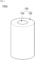
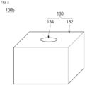
- FIGS. 1 and 2 are schematic diagrams showing an outer appearance of battery packs according to embodiments of the present disclosure
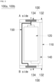
- FIG. 3 is a schematic diagram showing an internal configuration of the battery packs shown in FIGS. 1 and 2 .
- a battery pack 100a may be configured such that one battery cell 120 is accommodated in a cylindrical case 110.
- a battery pack 100b may be configured such that one battery cell 120 is accommodated in a hexahedral case 110.
- the cases 110 shown in FIGS. 1 and 2 have a different appearance but may have the same internal structure.
- Each of the case 110 forms an accommodation space therein to accommodate the battery cell 120.
- Cap assemblies 130 may be provided at upper and lower portions (or ends) of the cases 110, respectively.
- the cap assemblies 130 may include a first cap plate 132 and a second cap plate 134 in the shape of a disk or a rectangular plate corresponding to the shape of the case 110.
- the first cap plate 132 may be a negative electrode cap plate electrically connected to a negative electrode of the battery cell 120
- the second cap plate 134 may be a positive electrode cap plate electrically connected to a positive electrode of the battery cell 120.
- the first cap plate 132 may be a positive cap plate and the second cap plate 134 may be a negative cap plate.
- the size of the first cap plate 132 may be larger than that of the second cap plate 134, a hollow may be formed in the center of the first cap plate 132, and the second cap plate 134 may be inserted into the hollow, or vice versa.
- a pair of cap assemblies 130 respectively provided on the upper and lower portions of the case 110 may have the same structure and may be symmetrically disposed. Therefore, when the first cap plate 132 is a negative electrode cap plate, as shown in FIG. 3 , the pair of (both of the) first cap plates 132 may be connected to the negative electrode of the battery cell 120 by at least one negative electrode lead wire 140, respectively. When the second cap plate 134 is a positive electrode cap plate, as shown in FIG. 3 , the pair of (both of the) second cap plates 134 may be connected to the positive electrode of the battery cell 120 by at least one positive electrode lead wire 150, respectively.
- the negative electrode lead wire 140 and the positive electrode lead wire 150 are disposed so as not to overlap each other.
- the first cap plate 132 and the second cap plate 134 may be insulated from each other by an insulator, and/or the first cap plate 132 and the case 110 may be insulated from each other by an insulator.
- the battery pack 100a has positive and negative electrodes on both sides thereof (e.g., on both ends thereof), upper and lower surfaces are essentially indistinguishable. Accordingly, in FIG. 3 , for convenience, the upper surface of the battery pack 100a is indicated as the A side and the lower surface is indicated as the B side. That is, as shown in FIG. 3 , in the battery pack 100a, positive and negative electrodes are present on the A side, and positive and negative electrodes are also present on the B side. Thus, charging and discharging are possible in either direction (e.g., are possible regardless of the orientation of the battery pack 100a).
- the battery cell 120 may be applied regardless of the shape thereof and may be, for example, a cylindrical battery, a prismatic battery, or a pouch-shaped battery.
- the battery cell 120 may include an electrode assembly and an electrolyte accommodated together in a cylindrical, prismatic, or pouch-type cell case.
- a positive terminal may be provided at one end of the battery cell, and a negative terminal may be provided at the other end of the battery cell.
- positive and negative terminals may be provided at one end of the battery cell, and positive and negative terminals also may be provided at the other end of the battery cell.
- the electrode assembly includes a negative electrode plate, a positive electrode plate, and a separator.
- the negative electrode plate includes a metal foil made of copper (Cu) or nickel (Ni) that is coated with a negative electrode active material, such as graphite or carbon on at least one surface thereof.
- the positive electrode plate includes a metal foil made of aluminum (Al) that is coated with a positive electrode active material made of a transition metal oxide on at least one surface thereof.
- the negative electrode plate and the positive electrode plate may each have a non-coating portion that is not coated with an active material.
- the separator may be interposed between the negative electrode plate and the positive electrode plate to prevent an electrical short between them while allowing lithium ions to move therebetween.
- the electrode assembly is formed by winding or stacking the negative electrode plate, the positive electrode plate, and the separator interposed therebetween.
- the electrode assembly is accommodated in a cell case together with an electrolyte, and a negative electrode terminal and a positive electrode terminal formed in the cell case may be electrically connected to the electrode assembly through respective uncoated portions.
- the respective uncoated portions may be electrically connected to the negative electrode terminal and the positive electrode terminal by lead wires or current collector plates.
- FIGS. 1 to 3 show an embodiment in which one battery cell 120 is accommodated in the case 110 to form the battery pack 100a.
- the battery pack 100a may include a plurality of battery cells 120.
- FIGS. 4 and 5 are perspective views schematically showing battery packs according to other embodiments of the present disclosure.
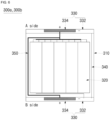
- FIG. 6 is a schematic diagram showing an internal configuration of the battery pack shown in FIGS. 4 and 5 .
- a battery pack 300a may be configured such that a plurality of battery cells 320 are accommodated in a cylindrical case 310.
- a battery pack 300b may be configured such that a plurality of battery cells 320 are accommodated in a hexahedral case 310.
- the battery cells 320 may be arranged in a single layer (one step) or may be arranged in multiple layers (multi-steps).
- the cases 310 shown in FIGS. 4 and 5 have a different appearance but may have the same internal structure.
- Each of the cases 310 forms an accommodation space therein to accommodate the battery cells 320.
- Cap assemblies 330 may be provided at upper and lower portions of the cases 310, respectively.
- the cap assemblies 330 may include a first cap plate 332 and a second cap plate 334 and may have the same structures as those of the previous embodiment. Thus, a detailed description thereof will be omitted. In addition, because each of the plurality of battery cells 320 is the same as in the foregoing embodiment, a detailed description thereof will be omitted.
- the negative electrode of each of the plurality of battery cells 320 may be electrically connected by a negative electrode lead wire 340 and electrically connected to the first cap plate 332.
- the positive electrode of each of the plurality of battery cells 320 may be electrically connected by a positive electrode lead wire 350 and electrically connected to the second cap plate 334.
- the negative electrode lead wire 340 and the positive electrode lead wire 350 are wire are disposed so as not to overlap each other. In the embodiments shown in FIGS. 4 and 5 , the negative electrode lead wire 340 is connected to the negative electrode located at a lower portion of the battery cell 320, but, for ease of understanding, it is shown at an upper portion of the battery cell 320.
- the negative electrode lead wire and the positive electrode lead wire may be both disposed on the upper portion. In an embodiment including one or more battery cells in which the negative electrode and the positive electrode are both located on the lower portion, the negative electrode lead wire and the positive electrode lead wire may be both disposed on the lower portion.
- the battery pack 300a, 300b has both a positive electrode and a negative electrode disposed on the A and B surfaces, respectively, charging and discharging can be performed in either direction.
- a structure in which a battery pack can be charged and discharged in both directions has been described, a single battery cell may have a structure in which bidirectional charging and discharging is possible.
- FIGS. 7 and 8 are schematic diagrams showing battery pack charging stations according to embodiments of the present disclosure.
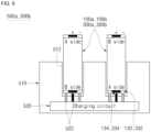
- FIG. 9 is a schematic diagram showing a structure of the battery pack charging stations shown in FIGS. 7 and 8 .
- battery pack charging stations 500a and 500b may each include a station main body 510, a plurality of receiving units 512 formed on one side of the station main body 510, and a charging circuit unit 520 provided inside the station main body 510.
- the station main body 510 may be formed in various shapes including, for example, a cylindrical shape and a hexahedral shape.
- the receiving units 512 may be formed on (or in) the upper side of the station main body 510, and the charging circuit unit 520 may be installed therein.
- the receiving units 512 are spaces for accommodating (e.g., for respectively accommodating) a plurality of battery packs, and each of the receiving units 512 has one end communicating with the outside and the other end connected to the charging circuit unit 520.
- the receiving units 512 may be configured to correspond to the shapes of the battery packs 100a, 100b, 300a, and 300b.
- the receiving units 512 may form accommodation spaces having a cylindrical or hexahedral shape.
- the battery packs 100a, 100b, 300a, and 300b may be connected to charging terminals 522 of the charging circuit unit 520 at inner lower ends of (e.g., at a bottom of) the receiving units 512.
- the charging circuit unit 520 is electrically connected to the battery packs 100a, 100b, 300a, and 300b and has mounted therein a charging circuit and various components for charging the battery packs 100a, 100b, 300a, and 300b.
- the charging circuit unit 520 may be configured in the same manner as or in a similar manner to charging units mounted in devices for charging a conventional battery pack.
- the charging circuit unit 520 may have charging terminals 522 corresponding to the number of receiving units 512. To this end, the charging terminals 522 may be exposed at the inner lower ends of the receiving units 512.
- the charging terminals 522 may include a negative electrode terminal and a positive electrode terminal electrically connected to a first cap plate 132 and a second cap plate 134 of each of the battery packs 100a, 100b, 300a, and 300b, respectively. Therefore, when the battery packs 100a, 100b, 300a, and 300b are mounted in the respective receiving units 512, the first cap plate 132 and the second cap plate 134 of the battery pack 100a, 100b, 300a, 300b are brought into contact with the negative electrode terminal and the positive electrode terminal, respectively. Thus, charging can be performed.
- the first cap plate 132 and the second cap plate 134 having a negative polarity and a positive polarity are provided at opposite ends, respectively. Accordingly, the battery packs 100a, 100b, 300a, and 300b can be charged regardless of which side of the battery pack 100a, 100b, 300a, or 300b faces the charging terminals 522.
- the battery pack charging station having the above-described configuration may be used for replacement of a battery pack for a drone.
- the drove may be considered as having any conventional drone structure, and thus, a detailed description thereof is omitted.
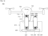
- FIG. 10 is a schematic diagram showing battery pack replacement in a drone according to an embodiment of the present disclosure.
- a drone 700 may include a main body 710 having a mounting unit 712 in (or on) which battery packs 100a, 100b, 300a, and 300b are mounted and a circuit unit 720 provided inside the main body 710 and having connection terminals 722.
- the mounting unit 712 is an accommodation space in which one or more battery packs 100a, 100b, 300a, and 300b are accommodated. Cap assemblies 130 (see, e.g., FIG. 3 ) of the battery packs 100a, 100b, 300a, and 300b may be exposed to the outside of the mounting unit 712 or may be completely inserted into (or completely accommodated in) the mounting unit 712. In FIG. 10 , for ease of understanding, the amount of the battery packs 100a, 100b, 300a, and 300b that is exposed outside of the mounting unit 712 is exaggerated.
- the cap assemblies 130 of the battery packs 100a, 100b, 300a, and 300b may be operated (or moved) to be exposed to the outside of the mounting unit 712 when the drone 700 approaches the charging stations 500a and 500b.
- the connection terminals 722 connected to the circuit unit 720 may be exposed at one side of (e.g., at one end of) the mounting unit 712.
- the connection terminals 722 may include negative electrode and positive electrode terminals that may be connected to the first cap plate 132 and the second cap plate 134 of the battery packs 100a, 100b, 300a, and 300b.
- the first cap plate 132 and the second cap plate 134 of the battery packs 100a, 100b, 300a, and 300b are brought into contact with the negative and positive electrode terminals, respectively, so that the drone 700 is able to use the power from the battery packs 100a, 100b, 300a, and 300b.
- the first cap plate 132 and the second cap plate 134 having a negative polarity and a positive polarity are provided at both opposite ends. Accordingly, the battery packs 100a, 100b, 300a, and 300b can supply power to the drone 700 regardless of which side of the battery pack 100a, 100b, 300a, or 300b faces the connection terminals 722.
- the drone 700 may approach the charging stations 500a and 500b. Thereafter, the drone 700 may mount (e.g., may load) the discharged battery packs 100a, 100b, 300a, and 300b into the receiving units 512 in the charging stations 500a and 500b. When the battery packs 100a, 100b, 300a, and 300b are mounted in the receiving units 512, the battery packs 100a, 100b, 300a, and 300b may be automatically separated from the drone 700.
- the drone 700 can fly to an adjacent receiving unit 512 and mount one or more fully charged battery packs 100a, 100b, 300a, and 300b in the mounting unit 712. Even after the battery packs 100a, 100b, 300a, and 300b are separated from the drone 700, the drone 700 should be able to fly to the adjacent receiving unit 512, and thus, internal batteries for supplying auxiliary power may be provided inside the drone 700.
- the internal batteries may be maintained at charge amounts enough to enable a minimum flight.
- the internal batteries can receive power from the battery packs 100a, 100b, 300a, and 300b.
- the drone 700 may resume flight by receiving power from the battery packs 100a, 100b, 300a, and 300b.
- a drone can be operated regardless of which direction the battery pack is installed.
- a charging station for a bidirectional rechargeable battery pack is provided, the battery pack can be charged regardless of the direction and battery replacement of the drone can be automated.
Landscapes
- Engineering & Computer Science (AREA)
- Chemical & Material Sciences (AREA)
- Chemical Kinetics & Catalysis (AREA)
- Electrochemistry (AREA)
- General Chemical & Material Sciences (AREA)
- Aviation & Aerospace Engineering (AREA)
- Power Engineering (AREA)
- Transportation (AREA)
- Mechanical Engineering (AREA)
- Combustion & Propulsion (AREA)
- Manufacturing & Machinery (AREA)
- Remote Sensing (AREA)
- Life Sciences & Earth Sciences (AREA)
- Sustainable Development (AREA)
- Sustainable Energy (AREA)
- Biophysics (AREA)
- Computer Hardware Design (AREA)
- Battery Mounting, Suspending (AREA)
- Connection Of Batteries Or Terminals (AREA)
- Secondary Cells (AREA)
- Charge And Discharge Circuits For Batteries Or The Like (AREA)
Abstract
Description
- Aspects of embodiments of the present disclosure relate to a bidirectional rechargeable battery pack, a drone having same, and a battery pack charging station.
- Generally, a drone is a kind of aircraft that flies in the sky by rotating a plurality of propellers (also called rotors) using battery power and is configured to enable flight in various patterns according to user's remote control operation. To fly a drone, the plurality of propellers must rotate very quickly, which results in relatively high battery consumption, and accordingly, there is a disadvantage in that the battery must be continuously replaced or recharged. Generally, replacing or charging drone batteries is done manually by users. In particular, because the direction (or orientation) of positive and negative poles of a battery are fixed, when batteries are mounted on a drone, the directions of polarities must be matched. Thus, battery replacement in the drone is difficult to be automated.
- The above information disclosed in this Background section is for enhancement of understanding of the background of the present disclosure, and therefore, it may contain information that does not constitute prior art.
- Embodiments of the present disclosure provide a bidirectional rechargeable battery pack, a drone having same, and a battery pack charging station.
- A battery pack, according to an embodiment of the present disclosure, includes: a battery cell including a negative electrode and a positive electrode; a case accommodating the battery cell; and a pair of cap assemblies at both ends of the case. Each of the cap assemblies includes a first cap plate and a second cap plate. The first cap plate is electrically connected to the battery cell and has one of a negative polarity or a positive polarity, and the second cap plate is electrically connected to the battery cell and has the other one of a negative polarity and a positive polarity.
- The battery cell may include a plurality of battery cells.
- The negative electrode may be at one end of the battery cell, and the positive electrode may be at another end of the battery cell.
- The negative electrode and the positive electrode may be at one end of the battery cell, and another negative electrode and another positive electrode may be at another end of the battery cell.
- The battery pack may further include: a negative electrode lead wire connecting the negative electrode of the battery cell with one of the first cap plate or the second cap plate; and a positive electrode lead wire connecting the positive electrode of the battery cell and the other one of the first cap plate or the second cap plate.
- The negative electrode lead wire and the positive electrode lead wire may not overlap each other.
- A battery pack charging station, according to an embodiment of the present disclosure, includes: a main body having a plurality of receiving units for accommodating the battery pack as described above; and a charging circuit unit inside the main body and configured to be electrically connected to the battery pack to charge the battery pack.
- The charging circuit unit may include a charging terminal exposed at an inside of the receiving units.
- The charging terminal may include a negative electrode terminal and a positive electrode terminal.
- A drone, according to an embodiment of the present disclosure, includes: a main body having a mounting unit configured to receive the battery pack as described above; and a circuit unit inside the main body and configured to be electrically connected to the battery pack.
- The circuit unit may include a connection terminal exposed at an inside of the mounting unit.
- The connection terminal may include a negative electrode terminal and a positive electrode terminal.
- The drone may further include an internal battery mounted inside the main body and configured to be supplied with power from the battery pack.
- At least some of the above and other features of the invention are set out in the claims.
-
-
FIGS. 1 and2 are schematic diagrams showing battery packs according to embodiments of the present disclosure. -
FIG. 3 is a schematic diagram showing an internal configuration of the battery packs shown inFIGS. 1 and2 . -
FIGS. 4 and5 are perspective views schematically showing battery packs according to other embodiments of the present disclosure. -
FIG. 6 is a schematic diagram showing an internal configuration of the battery packs shown inFIGS. 4 and5 . -
FIGS. 7 and 8 are schematic diagrams showing battery pack charging stations according to embodiments of the present disclosure. -
FIG. 9 is a schematic diagram showing a structure of the battery pack charging stations shown inFIGS. 7 and 8 . -
FIG. 10 is a schematic diagram showing battery pack replacement in a drone according to an embodiment of the present disclosure. - Embodiments of the present disclosure are provided to more completely explain aspects and features of the present disclosure to those skilled in the art, and the following embodiments may be modified in various other forms. In other words, the present disclosure may be embodied in many different forms and should not be construed as being limited to the embodiments set forth herein. Rather, these embodiments are provided so that this disclosure will be thorough and complete and will fully convey the aspects and features of the present disclosure to those skilled in the art.
- In the accompanying drawings, sizes or thicknesses of various components may be exaggerated for brevity and clarity. Like numbers refer to like elements throughout. As used herein, the term "and/or" includes any and all combinations of one or more of the associated listed items. In addition, it will be understood that when an element A is referred to as being "connected to" an element B, the element A can be directly connected to the element B or an intervening element C may be present therebetween such that the element A and the element B are indirectly connected to each other. Expressions, such as "at least one of" and "any one of," when preceding a list of elements, modify the entire list of elements and do not modify the individual elements of the list. For example, the expression "at least one of a, b, or c" indicates only a, only b, only c, both a and b, both a and c, both b and c, all of a, b, and c, or variations thereof. As used herein, the terms "use," "using," and "used" may be considered synonymous with the terms "utilize," "utilizing," and "utilized," respectively. As used herein, the terms "substantially," "about," and similar terms are used as terms of approximation and not as terms of degree, and are intended to account for the inherent variations in measured or calculated values that would be recognized by those of ordinary skill in the art.
- The terminology used herein is for the purpose of describing particular embodiments only and is not intended to be limiting of the disclosure. As used herein, the singular forms are intended to include the plural forms as well, unless the context clearly indicates otherwise. It will be further understood that the terms "comprise" or "include" and/or "comprising" or "including," when used in this specification, specify the presence of stated features, numbers, steps, operations, elements, and/or components but do not preclude the presence or addition of one or more other features, numbers, steps, operations, elements, components, and/or groups thereof.
- It will be understood that, although the terms first, second, etc. may be used herein to describe various members, elements, regions, layers and/or sections, these members, elements, regions, layers and/or sections should not be limited by these terms. These terms are only used to distinguish one member, element, region, layer and/or section from another. Thus, for example, a first member, a first element, a first region, a first layer and/or a first section discussed below could be termed a second member, a second element, a second region, a second layer and/or a second section without departing from the teachings of the present disclosure.
- Spatially relative terms, such as "beneath," "below," "lower," "above," "upper," and the like, may be used herein for ease of description to describe one element or feature's relationship to another element(s) or feature(s) as illustrated in the figures. It will be understood that the spatially relative terms are intended to encompass different orientations of the device in use or operation in addition to the orientation depicted in the figures. For example, if the element or feature in the figures is turned over, elements described as "below" or "beneath" other elements or features would then be oriented "on" or "above" the other elements or features. Thus, the exemplary term "below" can encompass both an orientation of above and below.
- Hereinafter, a bidirectional rechargeable battery pack, a drone having the same, and a battery pack charging station, according to embodiments of the present disclosure, will be described, in detail, with reference to the accompanying drawings.
- First, a battery pack according to embodiments of the present disclosure will be described.
-
FIGS. 1 and2 are schematic diagrams showing an outer appearance of battery packs according to embodiments of the present disclosure, andFIG. 3 is a schematic diagram showing an internal configuration of the battery packs shown inFIGS. 1 and2 . - Referring to
FIGS. 1 and3 , abattery pack 100a, according to an embodiment of the present disclosure, may be configured such that onebattery cell 120 is accommodated in acylindrical case 110. In another embodiment, referring toFIGS. 2 and3 , abattery pack 100b may be configured such that onebattery cell 120 is accommodated in ahexahedral case 110. - The
cases 110 shown inFIGS. 1 and2 have a different appearance but may have the same internal structure. Each of thecase 110 forms an accommodation space therein to accommodate thebattery cell 120.Cap assemblies 130 may be provided at upper and lower portions (or ends) of thecases 110, respectively. - The
cap assemblies 130 may include afirst cap plate 132 and asecond cap plate 134 in the shape of a disk or a rectangular plate corresponding to the shape of thecase 110. For example, thefirst cap plate 132 may be a negative electrode cap plate electrically connected to a negative electrode of thebattery cell 120, and thesecond cap plate 134 may be a positive electrode cap plate electrically connected to a positive electrode of thebattery cell 120. However, in other embodiments, thefirst cap plate 132 may be a positive cap plate and thesecond cap plate 134 may be a negative cap plate. In some embodiments, the size of thefirst cap plate 132 may be larger than that of thesecond cap plate 134, a hollow may be formed in the center of thefirst cap plate 132, and thesecond cap plate 134 may be inserted into the hollow, or vice versa. - A pair of
cap assemblies 130 respectively provided on the upper and lower portions of thecase 110 may have the same structure and may be symmetrically disposed. Therefore, when thefirst cap plate 132 is a negative electrode cap plate, as shown inFIG. 3 , the pair of (both of the)first cap plates 132 may be connected to the negative electrode of thebattery cell 120 by at least one negativeelectrode lead wire 140, respectively. When thesecond cap plate 134 is a positive electrode cap plate, as shown inFIG. 3 , the pair of (both of the)second cap plates 134 may be connected to the positive electrode of thebattery cell 120 by at least one positiveelectrode lead wire 150, respectively. The negativeelectrode lead wire 140 and the positiveelectrode lead wire 150 are disposed so as not to overlap each other. - The
first cap plate 132 and thesecond cap plate 134 may be insulated from each other by an insulator, and/or thefirst cap plate 132 and thecase 110 may be insulated from each other by an insulator. Because thebattery pack 100a has positive and negative electrodes on both sides thereof (e.g., on both ends thereof), upper and lower surfaces are essentially indistinguishable. Accordingly, inFIG. 3 , for convenience, the upper surface of thebattery pack 100a is indicated as the A side and the lower surface is indicated as the B side. That is, as shown inFIG. 3 , in thebattery pack 100a, positive and negative electrodes are present on the A side, and positive and negative electrodes are also present on the B side. Thus, charging and discharging are possible in either direction (e.g., are possible regardless of the orientation of thebattery pack 100a). - The
battery cell 120 may be applied regardless of the shape thereof and may be, for example, a cylindrical battery, a prismatic battery, or a pouch-shaped battery. Thebattery cell 120 may include an electrode assembly and an electrolyte accommodated together in a cylindrical, prismatic, or pouch-type cell case. - A positive terminal may be provided at one end of the battery cell, and a negative terminal may be provided at the other end of the battery cell. Alternatively, positive and negative terminals may be provided at one end of the battery cell, and positive and negative terminals also may be provided at the other end of the battery cell.
- The electrode assembly includes a negative electrode plate, a positive electrode plate, and a separator. The negative electrode plate includes a metal foil made of copper (Cu) or nickel (Ni) that is coated with a negative electrode active material, such as graphite or carbon on at least one surface thereof. The positive electrode plate includes a metal foil made of aluminum (Al) that is coated with a positive electrode active material made of a transition metal oxide on at least one surface thereof. The negative electrode plate and the positive electrode plate may each have a non-coating portion that is not coated with an active material. The separator may be interposed between the negative electrode plate and the positive electrode plate to prevent an electrical short between them while allowing lithium ions to move therebetween. The electrode assembly is formed by winding or stacking the negative electrode plate, the positive electrode plate, and the separator interposed therebetween. The electrode assembly is accommodated in a cell case together with an electrolyte, and a negative electrode terminal and a positive electrode terminal formed in the cell case may be electrically connected to the electrode assembly through respective uncoated portions. The respective uncoated portions may be electrically connected to the negative electrode terminal and the positive electrode terminal by lead wires or current collector plates.
FIGS. 1 to 3 show an embodiment in which onebattery cell 120 is accommodated in thecase 110 to form thebattery pack 100a. However, thebattery pack 100a may include a plurality ofbattery cells 120. -
FIGS. 4 and5 are perspective views schematically showing battery packs according to other embodiments of the present disclosure.FIG. 6 is a schematic diagram showing an internal configuration of the battery pack shown inFIGS. 4 and5 . - Referring to
FIG. 4 , abattery pack 300a, according to an embodiment of the present disclosure, may be configured such that a plurality ofbattery cells 320 are accommodated in acylindrical case 310. In another embodiment, referring toFIG. 5 , abattery pack 300b, according to an embodiment of the present disclosure, may be configured such that a plurality ofbattery cells 320 are accommodated in ahexahedral case 310. Thebattery cells 320 may be arranged in a single layer (one step) or may be arranged in multiple layers (multi-steps). - The
cases 310 shown inFIGS. 4 and5 have a different appearance but may have the same internal structure. Each of thecases 310 forms an accommodation space therein to accommodate thebattery cells 320.Cap assemblies 330 may be provided at upper and lower portions of thecases 310, respectively. - The
cap assemblies 330 may include afirst cap plate 332 and asecond cap plate 334 and may have the same structures as those of the previous embodiment. Thus, a detailed description thereof will be omitted. In addition, because each of the plurality ofbattery cells 320 is the same as in the foregoing embodiment, a detailed description thereof will be omitted. - The negative electrode of each of the plurality of
battery cells 320 may be electrically connected by a negativeelectrode lead wire 340 and electrically connected to thefirst cap plate 332. The positive electrode of each of the plurality ofbattery cells 320 may be electrically connected by a positiveelectrode lead wire 350 and electrically connected to thesecond cap plate 334. The negativeelectrode lead wire 340 and the positiveelectrode lead wire 350 are wire are disposed so as not to overlap each other. In the embodiments shown inFIGS. 4 and5 , the negativeelectrode lead wire 340 is connected to the negative electrode located at a lower portion of thebattery cell 320, but, for ease of understanding, it is shown at an upper portion of thebattery cell 320. In an embodiment including one or more battery cells in which the negative electrode and the positive electrode are both located on the upper portion, the negative electrode lead wire and the positive electrode lead wire may be both disposed on the upper portion. In an embodiment including one or more battery cells in which the negative electrode and the positive electrode are both located on the lower portion, the negative electrode lead wire and the positive electrode lead wire may be both disposed on the lower portion. - As described above, because the
battery pack - Hereinafter, a charging station for charging a battery pack and a method for replacing a battery pack of a drone according to embodiments of the present disclosure will be described.
-
FIGS. 7 and 8 are schematic diagrams showing battery pack charging stations according to embodiments of the present disclosure.FIG. 9 is a schematic diagram showing a structure of the battery pack charging stations shown inFIGS. 7 and 8 . - Referring to
FIGS. 7 and 8 , batterypack charging stations main body 510, a plurality of receivingunits 512 formed on one side of the stationmain body 510, and acharging circuit unit 520 provided inside the stationmain body 510. - The station
main body 510 may be formed in various shapes including, for example, a cylindrical shape and a hexahedral shape. The receivingunits 512 may be formed on (or in) the upper side of the stationmain body 510, and the chargingcircuit unit 520 may be installed therein. - The receiving
units 512 are spaces for accommodating (e.g., for respectively accommodating) a plurality of battery packs, and each of the receivingunits 512 has one end communicating with the outside and the other end connected to the chargingcircuit unit 520. The receivingunits 512 may be configured to correspond to the shapes of thebattery packs units 512 may form accommodation spaces having a cylindrical or hexahedral shape. The battery packs 100a, 100b, 300a, and 300b may be connected to chargingterminals 522 of the chargingcircuit unit 520 at inner lower ends of (e.g., at a bottom of) the receivingunits 512. - As shown in
FIG. 9 , the chargingcircuit unit 520 is electrically connected to thebattery packs battery packs circuit unit 520 may be configured in the same manner as or in a similar manner to charging units mounted in devices for charging a conventional battery pack. The chargingcircuit unit 520 may have chargingterminals 522 corresponding to the number of receivingunits 512. To this end, the chargingterminals 522 may be exposed at the inner lower ends of the receivingunits 512. The chargingterminals 522 may include a negative electrode terminal and a positive electrode terminal electrically connected to afirst cap plate 132 and asecond cap plate 134 of each of thebattery packs battery packs units 512, thefirst cap plate 132 and thesecond cap plate 134 of thebattery pack battery packs first cap plate 132 and thesecond cap plate 134 having a negative polarity and a positive polarity are provided at opposite ends, respectively. Accordingly, thebattery packs battery pack terminals 522. - The battery pack charging station having the above-described configuration may be used for replacement of a battery pack for a drone. As referred to herein, the drove may be considered as having any conventional drone structure, and thus, a detailed description thereof is omitted.
-
FIG. 10 is a schematic diagram showing battery pack replacement in a drone according to an embodiment of the present disclosure. - As shown in
FIG. 10 , adrone 700 may include amain body 710 having a mountingunit 712 in (or on) which battery packs 100a, 100b, 300a, and 300b are mounted and acircuit unit 720 provided inside themain body 710 and havingconnection terminals 722. - The mounting
unit 712 is an accommodation space in which one ormore battery packs FIG. 3 ) of thebattery packs unit 712 or may be completely inserted into (or completely accommodated in) the mountingunit 712. InFIG. 10 , for ease of understanding, the amount of thebattery packs unit 712 is exaggerated. In an embodiment in which thebattery packs unit 712, thecap assemblies 130 of thebattery packs unit 712 when thedrone 700 approaches the chargingstations connection terminals 722 connected to thecircuit unit 720 may be exposed at one side of (e.g., at one end of) the mountingunit 712. Theconnection terminals 722 may include negative electrode and positive electrode terminals that may be connected to thefirst cap plate 132 and thesecond cap plate 134 of thebattery packs battery packs unit 712, thefirst cap plate 132 and thesecond cap plate 134 of thebattery packs drone 700 is able to use the power from thebattery packs battery packs first cap plate 132 and thesecond cap plate 134 having a negative polarity and a positive polarity are provided at both opposite ends. Accordingly, thebattery packs drone 700 regardless of which side of thebattery pack connection terminals 722. - When the discharge amount of the
battery packs drone 700 may approach the chargingstations drone 700 may mount (e.g., may load) the dischargedbattery packs units 512 in the chargingstations battery packs units 512, thebattery packs drone 700. After thebattery packs drone 700 can fly to anadjacent receiving unit 512 and mount one or more fully chargedbattery packs unit 712. Even after thebattery packs drone 700, thedrone 700 should be able to fly to theadjacent receiving unit 512, and thus, internal batteries for supplying auxiliary power may be provided inside thedrone 700. The internal batteries may be maintained at charge amounts enough to enable a minimum flight. The internal batteries can receive power from thebattery packs battery packs drone 700 may resume flight by receiving power from thebattery packs - As described above, according to embodiments of the present disclosure, because a negative electrode and a positive electrode are provided at both sides (e.g., at both ends) of the battery pack, a drone can be operated regardless of which direction the battery pack is installed. In addition, because a charging station for a bidirectional rechargeable battery pack is provided, the battery pack can be charged regardless of the direction and battery replacement of the drone can be automated.
- The foregoing embodiments are only some embodiments for carrying out the present disclosure, which is not limited thereto. It will be understood by a person skilled in the art that various changes in form and details may be made therein without departing from the scope of the present disclosure as defined by the following claims and their equivalents.
Claims (13)
- A battery pack comprising:a battery cell comprising a negative electrode and a positive electrode;a case accommodating the battery cell; anda pair of cap assemblies at both ends of the case, each of the cap assemblies comprising a first cap plate and a second cap plate, the first cap plate being electrically connected to the battery cell and having one of a negative polarity or a positive polarity, and the second cap plate being electrically connected to the battery cell and having the other one of a negative polarity and a positive polarity.
- The battery pack as claimed in claim 1, wherein the battery cell comprises a plurality of battery cells.
- The battery pack as claimed in claim 1 or 2, wherein the negative electrode is at one end of the battery cell, and the positive electrode is at another end of the battery cell.
- The battery pack as claimed in claim 1 or 2, wherein the negative electrode and the positive electrode are at one end of the battery cell, and another negative electrode and another positive electrode are at another end of the battery cell.
- The battery pack as claimed in any preceding claim, further comprising:a negative electrode lead wire connecting the negative electrode of the battery cell with one of the first cap plate or the second cap plate; anda positive electrode lead wire connecting the positive electrode of the battery cell and the other one of the first cap plate or the second cap plate.
- The battery pack as claimed in claim 5, wherein the negative electrode lead wire and the positive electrode lead wire do not overlap each other.
- A battery pack charging station comprising:a main body having a plurality of receiving units for accommodating the battery pack as claimed in any preceding claim; anda charging circuit unit inside the main body and configured to be electrically connected to the battery pack to charge the battery pack.
- The battery pack charging station as claimed in claim 7, wherein the charging circuit unit comprises a charging terminal exposed at an inside of the receiving units.
- The battery pack charging station as claimed in claim 8, wherein the charging terminal comprises a negative electrode terminal and a positive electrode terminal.
- A drone comprising:a main body having a mounting unit configured to receive the battery pack as claimed in any of claims 1 to 6; anda circuit unit inside the main body and configured to be electrically connected to the battery pack.
- The drone as claimed in claim 10, wherein the circuit unit comprises a connection terminal exposed at an inside of the mounting unit.
- The drone as claimed in claim 11, wherein the connection terminal comprises a negative electrode terminal and a positive electrode terminal.
- The drone as claimed in any of claims 10 to 12, further comprising an internal battery mounted inside the main body and configured to be supplied with power from the battery pack.
Applications Claiming Priority (1)
| Application Number | Priority Date | Filing Date | Title |
|---|---|---|---|
| KR1020230006133A KR20240114123A (en) | 2023-01-16 | 2023-01-16 | Bidirectional rechargeable battery pack and drone having it, and charging stations for battery packs |
Publications (2)
| Publication Number | Publication Date |
|---|---|
| EP4411934A2 true EP4411934A2 (en) | 2024-08-07 |
| EP4411934A3 EP4411934A3 (en) | 2024-10-09 |
Family
ID=89618877
Family Applications (1)
| Application Number | Title | Priority Date | Filing Date |
|---|---|---|---|
| EP24151401.7A Pending EP4411934A3 (en) | 2023-01-16 | 2024-01-11 | Bidirectional rechargeable battery pack, drone having the same, and battery pack charging station |
Country Status (5)
| Country | Link |
|---|---|
| US (1) | US20240243413A1 (en) |
| EP (1) | EP4411934A3 (en) |
| JP (1) | JP7793584B2 (en) |
| KR (1) | KR20240114123A (en) |
| CN (1) | CN118352724A (en) |
Family Cites Families (8)
| Publication number | Priority date | Publication date | Assignee | Title |
|---|---|---|---|---|
| JP2001143716A (en) * | 1999-11-16 | 2001-05-25 | Tai-Her Yang | Cylindrical single electrode battery |
| TWI493776B (en) * | 2014-03-14 | 2015-07-21 | 廣東正飛移動照明有限公司 | Five pole battery box structure |
| US20170072812A1 (en) * | 2015-09-16 | 2017-03-16 | Qualcomm Incorporated | Battery Management Systems for Autonomous Vehicles |
| US11056895B2 (en) * | 2017-10-18 | 2021-07-06 | Black & Decker Inc. | Multi-port charger |
| GB2572549A (en) * | 2018-03-28 | 2019-10-09 | Sony Corp | Unmanned aerial vehicle |
| KR20200018003A (en) * | 2018-08-10 | 2020-02-19 | 남 영 김 | Dual battery auto change system |
| CN212461949U (en) * | 2020-06-20 | 2021-02-02 | 东莞市瑞迪三维电子科技有限公司 | Novel battery pack |
| JP2022054199A (en) * | 2020-09-25 | 2022-04-06 | eVTOL Japan株式会社 | Electrically-driven rotary-wing aircraft |
-
2023
- 2023-01-16 KR KR1020230006133A patent/KR20240114123A/en active Pending
- 2023-11-24 JP JP2023199231A patent/JP7793584B2/en active Active
- 2023-11-27 US US18/520,210 patent/US20240243413A1/en active Pending
-
2024
- 2024-01-11 EP EP24151401.7A patent/EP4411934A3/en active Pending
- 2024-01-11 CN CN202410044511.7A patent/CN118352724A/en active Pending
Also Published As
| Publication number | Publication date |
|---|---|
| JP7793584B2 (en) | 2026-01-05 |
| JP2024100694A (en) | 2024-07-26 |
| EP4411934A3 (en) | 2024-10-09 |
| KR20240114123A (en) | 2024-07-23 |
| US20240243413A1 (en) | 2024-07-18 |
| CN118352724A (en) | 2024-07-16 |
Similar Documents
| Publication | Publication Date | Title |
|---|---|---|
| US7611800B2 (en) | Battery module | |
| US9209478B2 (en) | Elongated mandrel for a winding device | |
| US7399554B2 (en) | Hybrid rechargeable battery having high power and high energy density lithium cells | |
| US9263762B2 (en) | Lithium ion batteries | |
| US6858345B2 (en) | Wound bipolar lithium polymer batteries | |
| CN112310569B (en) | Battery monomer, battery module, battery pack, device and processing method | |
| JP2008140773A (en) | Battery module | |
| KR102734115B1 (en) | A positive electrode and an electrode assembly comprising the positive electrode | |
| KR101991231B1 (en) | Solid state battery with offset geometry | |
| US9123924B2 (en) | Battery core and method of manufacturing the same | |
| EP4250406A1 (en) | Electrode assembly and manufacturing method and system, battery cell, battery, and power utilization apparatus | |
| US20180097217A1 (en) | Separator for a battery cell and battery cell | |
| EP4095965B1 (en) | Electrode assembly, battery cell, battery, electrical device | |
| EP4411934A2 (en) | Bidirectional rechargeable battery pack, drone having the same, and battery pack charging station | |
| KR20210021839A (en) | Rechargeable battery | |
| EP4576294A1 (en) | Battery cell and electrode assembly | |
| CN223124164U (en) | Secondary battery and secondary battery module | |
| EP4693720A1 (en) | Noise prevention insulation tape and battery pack adopting the same | |
| EP4730516A1 (en) | Battery cell holder and battery pack | |
| KR20250137458A (en) | rechargeable battery pack | |
| US10811732B1 (en) | Pre-lithiation for batteries having si-anodes | |
| KR20250129463A (en) | Rivet terminal, rechargeable battery comprising the same and manufacturing method thereof | |
| KR20260001726A (en) | Secondary battery including electrode assembly laterally inserted in case, and manufactured method thereof | |
| KR20260013349A (en) | Secondary battery including electrode assembly laterally inserted in case, and manufactured method thereof | |
| KR20250122771A (en) | Electrode assembly and battery cell including the same |
Legal Events
| Date | Code | Title | Description |
|---|---|---|---|
| PUAI | Public reference made under article 153(3) epc to a published international application that has entered the european phase |
Free format text: ORIGINAL CODE: 0009012 |
|
| STAA | Information on the status of an ep patent application or granted ep patent |
Free format text: STATUS: REQUEST FOR EXAMINATION WAS MADE |
|
| 17P | Request for examination filed |
Effective date: 20240111 |
|
| AK | Designated contracting states |
Kind code of ref document: A2 Designated state(s): AL AT BE BG CH CY CZ DE DK EE ES FI FR GB GR HR HU IE IS IT LI LT LU LV MC ME MK MT NL NO PL PT RO RS SE SI SK SM TR |
|
| PUAL | Search report despatched |
Free format text: ORIGINAL CODE: 0009013 |
|
| AK | Designated contracting states |
Kind code of ref document: A3 Designated state(s): AL AT BE BG CH CY CZ DE DK EE ES FI FR GB GR HR HU IE IS IT LI LT LU LV MC ME MK MT NL NO PL PT RO RS SE SI SK SM TR |
|
| RIC1 | Information provided on ipc code assigned before grant |
Ipc: H01M 50/548 20210101ALI20240904BHEP Ipc: H01M 50/514 20210101ALI20240904BHEP Ipc: H01M 50/247 20210101ALI20240904BHEP Ipc: H01M 50/213 20210101ALI20240904BHEP Ipc: H01M 50/204 20210101ALI20240904BHEP Ipc: H01M 10/04 20060101ALI20240904BHEP Ipc: H02J 7/00 20060101ALI20240904BHEP Ipc: H01M 50/502 20210101ALI20240904BHEP Ipc: H01M 50/298 20210101ALI20240904BHEP Ipc: H01M 50/296 20210101ALI20240904BHEP Ipc: H01M 50/249 20210101ALI20240904BHEP Ipc: H01M 50/202 20210101ALI20240904BHEP Ipc: H01M 10/46 20060101AFI20240904BHEP |