EP4411907A1 - Power storage device and method for producing the same - Google Patents
Power storage device and method for producing the same Download PDFInfo
- Publication number
- EP4411907A1 EP4411907A1 EP23214661.3A EP23214661A EP4411907A1 EP 4411907 A1 EP4411907 A1 EP 4411907A1 EP 23214661 A EP23214661 A EP 23214661A EP 4411907 A1 EP4411907 A1 EP 4411907A1
- Authority
- EP
- European Patent Office
- Prior art keywords
- case
- electrode
- electrode body
- wall portion
- primary wall
- Prior art date
- Legal status (The legal status is an assumption and is not a legal conclusion. Google has not performed a legal analysis and makes no representation as to the accuracy of the status listed.)
- Pending
Links
Images






Classifications
-
- H—ELECTRICITY
- H01—ELECTRIC ELEMENTS
- H01M—PROCESSES OR MEANS, e.g. BATTERIES, FOR THE DIRECT CONVERSION OF CHEMICAL ENERGY INTO ELECTRICAL ENERGY
- H01M10/00—Secondary cells; Manufacture thereof
- H01M10/04—Construction or manufacture in general
- H01M10/0481—Compression means other than compression means for stacks of electrodes and separators
-
- H—ELECTRICITY
- H01—ELECTRIC ELEMENTS
- H01M—PROCESSES OR MEANS, e.g. BATTERIES, FOR THE DIRECT CONVERSION OF CHEMICAL ENERGY INTO ELECTRICAL ENERGY
- H01M10/00—Secondary cells; Manufacture thereof
- H01M10/04—Construction or manufacture in general
- H01M10/0431—Cells with wound or folded electrodes
-
- H—ELECTRICITY
- H01—ELECTRIC ELEMENTS
- H01M—PROCESSES OR MEANS, e.g. BATTERIES, FOR THE DIRECT CONVERSION OF CHEMICAL ENERGY INTO ELECTRICAL ENERGY
- H01M10/00—Secondary cells; Manufacture thereof
- H01M10/04—Construction or manufacture in general
- H01M10/0468—Compression means for stacks of electrodes and separators
-
- H—ELECTRICITY
- H01—ELECTRIC ELEMENTS
- H01M—PROCESSES OR MEANS, e.g. BATTERIES, FOR THE DIRECT CONVERSION OF CHEMICAL ENERGY INTO ELECTRICAL ENERGY
- H01M10/00—Secondary cells; Manufacture thereof
- H01M10/04—Construction or manufacture in general
- H01M10/0404—Machines for assembling batteries
- H01M10/0409—Machines for assembling batteries for cells with wound electrodes
-
- H—ELECTRICITY
- H01—ELECTRIC ELEMENTS
- H01M—PROCESSES OR MEANS, e.g. BATTERIES, FOR THE DIRECT CONVERSION OF CHEMICAL ENERGY INTO ELECTRICAL ENERGY
- H01M10/00—Secondary cells; Manufacture thereof
- H01M10/04—Construction or manufacture in general
- H01M10/049—Processes for forming or storing electrodes in the battery container
-
- H—ELECTRICITY
- H01—ELECTRIC ELEMENTS
- H01M—PROCESSES OR MEANS, e.g. BATTERIES, FOR THE DIRECT CONVERSION OF CHEMICAL ENERGY INTO ELECTRICAL ENERGY
- H01M10/00—Secondary cells; Manufacture thereof
- H01M10/05—Accumulators with non-aqueous electrolyte
- H01M10/052—Li-accumulators
- H01M10/0525—Rocking-chair batteries, i.e. batteries with lithium insertion or intercalation in both electrodes; Lithium-ion batteries
-
- H—ELECTRICITY
- H01—ELECTRIC ELEMENTS
- H01M—PROCESSES OR MEANS, e.g. BATTERIES, FOR THE DIRECT CONVERSION OF CHEMICAL ENERGY INTO ELECTRICAL ENERGY
- H01M10/00—Secondary cells; Manufacture thereof
- H01M10/05—Accumulators with non-aqueous electrolyte
- H01M10/058—Construction or manufacture
- H01M10/0587—Construction or manufacture of accumulators having only wound construction elements, i.e. wound positive electrodes, wound negative electrodes and wound separators
-
- H—ELECTRICITY
- H01—ELECTRIC ELEMENTS
- H01M—PROCESSES OR MEANS, e.g. BATTERIES, FOR THE DIRECT CONVERSION OF CHEMICAL ENERGY INTO ELECTRICAL ENERGY
- H01M50/00—Constructional details or processes of manufacture of the non-active parts of electrochemical cells other than fuel cells, e.g. hybrid cells
- H01M50/10—Primary casings; Jackets or wrappings
- H01M50/102—Primary casings; Jackets or wrappings characterised by their shape or physical structure
- H01M50/103—Primary casings; Jackets or wrappings characterised by their shape or physical structure prismatic or rectangular
-
- H—ELECTRICITY
- H01—ELECTRIC ELEMENTS
- H01M—PROCESSES OR MEANS, e.g. BATTERIES, FOR THE DIRECT CONVERSION OF CHEMICAL ENERGY INTO ELECTRICAL ENERGY
- H01M50/00—Constructional details or processes of manufacture of the non-active parts of electrochemical cells other than fuel cells, e.g. hybrid cells
- H01M50/10—Primary casings; Jackets or wrappings
- H01M50/147—Lids or covers
- H01M50/148—Lids or covers characterised by their shape
- H01M50/15—Lids or covers characterised by their shape for prismatic or rectangular cells
-
- H—ELECTRICITY
- H01—ELECTRIC ELEMENTS
- H01M—PROCESSES OR MEANS, e.g. BATTERIES, FOR THE DIRECT CONVERSION OF CHEMICAL ENERGY INTO ELECTRICAL ENERGY
- H01M50/00—Constructional details or processes of manufacture of the non-active parts of electrochemical cells other than fuel cells, e.g. hybrid cells
- H01M50/10—Primary casings; Jackets or wrappings
- H01M50/147—Lids or covers
- H01M50/155—Lids or covers characterised by the material
- H01M50/157—Inorganic material
- H01M50/159—Metals
-
- H—ELECTRICITY
- H01—ELECTRIC ELEMENTS
- H01M—PROCESSES OR MEANS, e.g. BATTERIES, FOR THE DIRECT CONVERSION OF CHEMICAL ENERGY INTO ELECTRICAL ENERGY
- H01M50/00—Constructional details or processes of manufacture of the non-active parts of electrochemical cells other than fuel cells, e.g. hybrid cells
- H01M50/10—Primary casings; Jackets or wrappings
- H01M50/172—Arrangements of electric connectors penetrating the casing
- H01M50/174—Arrangements of electric connectors penetrating the casing adapted for the shape of the cells
- H01M50/176—Arrangements of electric connectors penetrating the casing adapted for the shape of the cells for prismatic or rectangular cells
-
- H—ELECTRICITY
- H01—ELECTRIC ELEMENTS
- H01M—PROCESSES OR MEANS, e.g. BATTERIES, FOR THE DIRECT CONVERSION OF CHEMICAL ENERGY INTO ELECTRICAL ENERGY
- H01M50/00—Constructional details or processes of manufacture of the non-active parts of electrochemical cells other than fuel cells, e.g. hybrid cells
- H01M50/40—Separators; Membranes; Diaphragms; Spacing elements inside cells
- H01M50/471—Spacing elements inside cells other than separators, membranes or diaphragms; Manufacturing processes thereof
- H01M50/474—Spacing elements inside cells other than separators, membranes or diaphragms; Manufacturing processes thereof characterised by their position inside the cells
-
- H—ELECTRICITY
- H01—ELECTRIC ELEMENTS
- H01M—PROCESSES OR MEANS, e.g. BATTERIES, FOR THE DIRECT CONVERSION OF CHEMICAL ENERGY INTO ELECTRICAL ENERGY
- H01M50/00—Constructional details or processes of manufacture of the non-active parts of electrochemical cells other than fuel cells, e.g. hybrid cells
- H01M50/40—Separators; Membranes; Diaphragms; Spacing elements inside cells
- H01M50/471—Spacing elements inside cells other than separators, membranes or diaphragms; Manufacturing processes thereof
- H01M50/477—Spacing elements inside cells other than separators, membranes or diaphragms; Manufacturing processes thereof characterised by their shape
-
- H—ELECTRICITY
- H01—ELECTRIC ELEMENTS
- H01M—PROCESSES OR MEANS, e.g. BATTERIES, FOR THE DIRECT CONVERSION OF CHEMICAL ENERGY INTO ELECTRICAL ENERGY
- H01M50/00—Constructional details or processes of manufacture of the non-active parts of electrochemical cells other than fuel cells, e.g. hybrid cells
- H01M50/40—Separators; Membranes; Diaphragms; Spacing elements inside cells
- H01M50/471—Spacing elements inside cells other than separators, membranes or diaphragms; Manufacturing processes thereof
- H01M50/48—Spacing elements inside cells other than separators, membranes or diaphragms; Manufacturing processes thereof characterised by the material
-
- H—ELECTRICITY
- H01—ELECTRIC ELEMENTS
- H01M—PROCESSES OR MEANS, e.g. BATTERIES, FOR THE DIRECT CONVERSION OF CHEMICAL ENERGY INTO ELECTRICAL ENERGY
- H01M50/00—Constructional details or processes of manufacture of the non-active parts of electrochemical cells other than fuel cells, e.g. hybrid cells
- H01M50/40—Separators; Membranes; Diaphragms; Spacing elements inside cells
- H01M50/471—Spacing elements inside cells other than separators, membranes or diaphragms; Manufacturing processes thereof
- H01M50/48—Spacing elements inside cells other than separators, membranes or diaphragms; Manufacturing processes thereof characterised by the material
- H01M50/483—Inorganic material
-
- H—ELECTRICITY
- H01—ELECTRIC ELEMENTS
- H01M—PROCESSES OR MEANS, e.g. BATTERIES, FOR THE DIRECT CONVERSION OF CHEMICAL ENERGY INTO ELECTRICAL ENERGY
- H01M50/00—Constructional details or processes of manufacture of the non-active parts of electrochemical cells other than fuel cells, e.g. hybrid cells
- H01M50/40—Separators; Membranes; Diaphragms; Spacing elements inside cells
- H01M50/489—Separators, membranes, diaphragms or spacing elements inside the cells, characterised by their physical properties, e.g. swelling degree, hydrophilicity or shut down properties
-
- H—ELECTRICITY
- H01—ELECTRIC ELEMENTS
- H01M—PROCESSES OR MEANS, e.g. BATTERIES, FOR THE DIRECT CONVERSION OF CHEMICAL ENERGY INTO ELECTRICAL ENERGY
- H01M50/00—Constructional details or processes of manufacture of the non-active parts of electrochemical cells other than fuel cells, e.g. hybrid cells
- H01M50/50—Current conducting connections for cells or batteries
- H01M50/543—Terminals
- H01M50/547—Terminals characterised by the disposition of the terminals on the cells
-
- H—ELECTRICITY
- H01—ELECTRIC ELEMENTS
- H01M—PROCESSES OR MEANS, e.g. BATTERIES, FOR THE DIRECT CONVERSION OF CHEMICAL ENERGY INTO ELECTRICAL ENERGY
- H01M50/00—Constructional details or processes of manufacture of the non-active parts of electrochemical cells other than fuel cells, e.g. hybrid cells
- H01M50/60—Arrangements or processes for filling or topping-up with liquids; Arrangements or processes for draining liquids from casings
- H01M50/609—Arrangements or processes for filling with liquid, e.g. electrolytes
-
- H—ELECTRICITY
- H01—ELECTRIC ELEMENTS
- H01M—PROCESSES OR MEANS, e.g. BATTERIES, FOR THE DIRECT CONVERSION OF CHEMICAL ENERGY INTO ELECTRICAL ENERGY
- H01M50/00—Constructional details or processes of manufacture of the non-active parts of electrochemical cells other than fuel cells, e.g. hybrid cells
- H01M50/60—Arrangements or processes for filling or topping-up with liquids; Arrangements or processes for draining liquids from casings
- H01M50/609—Arrangements or processes for filling with liquid, e.g. electrolytes
- H01M50/627—Filling ports
-
- H—ELECTRICITY
- H01—ELECTRIC ELEMENTS
- H01M—PROCESSES OR MEANS, e.g. BATTERIES, FOR THE DIRECT CONVERSION OF CHEMICAL ENERGY INTO ELECTRICAL ENERGY
- H01M2220/00—Batteries for particular applications
- H01M2220/20—Batteries in motive systems, e.g. vehicle, ship, plane
-
- H—ELECTRICITY
- H01—ELECTRIC ELEMENTS
- H01M—PROCESSES OR MEANS, e.g. BATTERIES, FOR THE DIRECT CONVERSION OF CHEMICAL ENERGY INTO ELECTRICAL ENERGY
- H01M50/00—Constructional details or processes of manufacture of the non-active parts of electrochemical cells other than fuel cells, e.g. hybrid cells
- H01M50/50—Current conducting connections for cells or batteries
- H01M50/531—Electrode connections inside a battery casing
-
- Y—GENERAL TAGGING OF NEW TECHNOLOGICAL DEVELOPMENTS; GENERAL TAGGING OF CROSS-SECTIONAL TECHNOLOGIES SPANNING OVER SEVERAL SECTIONS OF THE IPC; TECHNICAL SUBJECTS COVERED BY FORMER USPC CROSS-REFERENCE ART COLLECTIONS [XRACs] AND DIGESTS
- Y02—TECHNOLOGIES OR APPLICATIONS FOR MITIGATION OR ADAPTATION AGAINST CLIMATE CHANGE
- Y02E—REDUCTION OF GREENHOUSE GAS [GHG] EMISSIONS, RELATED TO ENERGY GENERATION, TRANSMISSION OR DISTRIBUTION
- Y02E60/00—Enabling technologies; Technologies with a potential or indirect contribution to GHG emissions mitigation
- Y02E60/10—Energy storage using batteries
-
- Y—GENERAL TAGGING OF NEW TECHNOLOGICAL DEVELOPMENTS; GENERAL TAGGING OF CROSS-SECTIONAL TECHNOLOGIES SPANNING OVER SEVERAL SECTIONS OF THE IPC; TECHNICAL SUBJECTS COVERED BY FORMER USPC CROSS-REFERENCE ART COLLECTIONS [XRACs] AND DIGESTS
- Y02—TECHNOLOGIES OR APPLICATIONS FOR MITIGATION OR ADAPTATION AGAINST CLIMATE CHANGE
- Y02P—CLIMATE CHANGE MITIGATION TECHNOLOGIES IN THE PRODUCTION OR PROCESSING OF GOODS
- Y02P70/00—Climate change mitigation technologies in the production process for final industrial or consumer products
- Y02P70/50—Manufacturing or production processes characterised by the final manufactured product
Definitions
- the present disclosure relates to a rectangular power storage device in which an electrode body is housed in a rectangular parallelepiped box-like case and a method for producing the power storage device.
- Patent Document 1 JP2020-173893A
- binding a battery from outside with a binding member causes problems such as increase in cost, increase in a frame size, increase in weight, increase in the number of components, and others.
- the present disclosure has been made in view of the above circumstances and has a purpose of providing a power storage device achieving elastic compression of an electrode laminated portion of an electrode body in an electrode body thickness direction by the power storage device itself and also has a purpose of providing a method for producing the power storage device.
- the above-mentioned power storage device is configured such that the first primary wall portion and the second primary wall portion of the case elastically compress the electrode laminated portion of the electrode body in the electrode body thickness direction.
- this power storage device is of a self-compression type that elastically compresses the electrode laminated portion of the electrode body by the power storage device itself. Accordingly, no binding member needs to be separately prepared, or external binding by a simple binding member is enough in use of the power storage device.
- the above-mentioned power storage device is formed by joining the case body configuring the second primary wall portion and the four side wall portions to the lid configuring the first primary wall portion, and thus a power storage device of a self-compression type can be easily produced as mentioned below and the power storage device can be inexpensive.
- the "power storage device” for example, secondary batteries such as a lithium-ion secondary battery, capacitors such as a lithium ion capacitor, and all-solid-state batteries can be exemplified.
- an interposing member which is made of metal or resin and formed of a flat plate or a corrugated plate, may be interposed between the first primary wall portion of the case and the electrode laminated portion of the electrode body or between the second primary wall portion of the case and the electrode laminated portion of the electrode body.
- an elastic interposing member is provided to be elastically deformed in the case thickness direction to press the electrode laminated portion in the electrode body thickness direction in any one of between the first primary wall portion of the case and the electrode laminated portion of the electrode body and between the second primary wall portion of the case and the electrode laminated portion of the electrode body.
- the elastic interposing member is interposed between the first primary wall portion of the case and the electrode laminated portion of the electrode body or between the second primary wall portion of the case and the electrode laminated portion of the electrode body, and the electrode laminated portion is pressed by elastic deformation of the case and the elastic interposing member.
- the elasticity coefficient of the elastic interposing member is easily changed as compared to the elasticity coefficient of the case, and thus application of the elastic interposing member achieves a power storage device in which the electrode laminated portion is pressed by a more appropriate pressing force.
- material for the "elastic interposing member” for example, metal such as aluminum, stainless steel, steel, copper, titanium, rubber, and plastic may be exemplified.
- the elastic interposing member is made of any one of aluminum and stainless steel.
- the elastic interposing member is made of aluminum or stainless steel, and thus the power storage device, in which the electrode laminated portion is pressed by an appropriate pressing force, can be achieved.
- At least any one of the first primary wall portion and the second primary wall portion of the case is provided with an elastically deforming portion which is elastically deformed in the case thickness direction to press the electrode laminated portion of the electrode body in the electrode body thickness direction.
- At least any one of the first primary wall portion and the second primary wall portion of the case includes the above-mentioned elastically deforming portion, and thus the power storage device in which the electrode laminated portion is pressed with the further appropriate pressing force can be achieved.
- metal such as aluminum, stainless steel, steel, copper, titanium, and plastic may be exemplified.
- the case comprising the elastically deforming portion is made of any one of aluminum and stainless steel.
- the case provided with the elastically deforming portion is made of aluminum or stainless steel, and thus the power storage device, in which the electrode laminated portion of the electrode body is pressed by the appropriate pressing force, can be achieved.
- an electrode terminal is connected to the electrode body in the case and penetrates through and extends outside the case, and the electrode terminal is fixed to any one of the side wall portions of the case.
- the first primary wall portion and the second primary wall portion of the adjacent power storage devices oppose to each other.
- the first primary wall portions of the adjacent power storage devices or the second primary wall portions of the adjacent power storage devices oppose to each other. Accordingly, in the power storage device in which the electrode terminal is fixed to the first primary wall portion or the second primary wall portion of the case, it is difficult to connect the electrode terminals of the adjacent power storage devices.
- the electrode terminal is not fixed to the first primary wall portion or the second primary wall portion but fixed to the side wall portion.
- the electrode terminals of the adjacent power storage devices can be easily joined by use of a bus bar and others.
- an electrolytic solution housed in the case is provided, and a liquid inlet communicating inside and outside of the case to inject the electrolytic solution into the case is provided in any one of the side wall portions of the case.
- the liquid inlet is provided in the side wall portion of the case. Therefore, in injecting the electrolytic solution, the power storage device can achieve easy injection in such a manner that the power storage device is placed with the side wall portion provided with the liquid inlet facing upward.
- Another aspect of the present disclosure is to provide a method for producing a power storage device comprising: a case; and an electrode body housed in the case; the case of a parallelepiped box-like shape including: a first primary wall portion of a rectangular shape; a second primary wall portion of a rectangular shape opposing to the first primary wall portion; and four side wall portions, each of which is of a rectangular shape, connects the first primary wall portion and the second primary wall portion, and extends in a case thickness direction, the electrode body including an electrode plate and an electrode laminated portion of a parallelepiped shape in which the electrode plates is laminated in an electrode body thickness direction, and the electrode body being housed in the case in such a position that the electrode body thickness direction is in parallel to the case thickness direction, wherein the case includes: a case body of a bottomed rectangular cylindrical shape configuring the second primary wall portion and the four side wall portions and being formed with an opening of a rectangular shape configured by the four side wall portions; and a lid of a rectangular shape configuring the first
- a case In a conventional rectangular battery, a case is configured with a case body of a bottomed rectangular cylindrical shape constituting a first primary wall portion, a second primary wall portion, and three side wall portions of the case and configured with a lid constituting another side wall portion.
- the battery with such a configuration is difficult to be produced as a battery of a self-compression type.
- a space between the first primary wall portion and the second primary wall portion of the case body is made narrower than a thickness of the electrode body or a sum of thicknesses of the electrode body and the interposing member in a battery provided with the above-mentioned interposing member for pressing and compressing the electrode laminated portion of the electrode body in the battery after assembling, so that the electrode body and the like is difficult to be inserted in the case body.
- the electrode body is firstly housed in the case body of the bottomed rectangular cylindrical shape constituting the second primary wall portion and the four side wall portions in a step of the housing, and thus the electrode body can be easily housed in the case body.
- the self-compression-type power storage device which elastically compresses the electrode laminated portion of the electrode body by the power storage device itself can be easily produced.
- joining by welding such as laser welding and joining by swaging may be adopted.
- the power storage device is provided with an elastic interposing member to be elastically deformed in the case thickness direction to press the electrode laminated portion in the electrode body thickness direction in any one of between the first primary wall portion of the case and the electrode laminated portion of the electrode body and between the second primary wall portion of the case and the electrode laminated portion of the electrode body, the housing is to overlap the elastic interposing member on the electrode laminated portion of the electrode body and to house the electrode body and the elastic interposing member in the case body, and the pressing and compressing is to press and compress the electrode laminated portion of the electrode body and the elastic interposing member in the electrode body thickness direction.
- the power storage device is produced with the above-mentioned elastic interposing member, and thus the power storage device, in which the electrode laminated portion of the electrode body is pressed with a more appropriate pressing force, can be produced.
- the elastic interposing member is made of any one of aluminum and stainless steel.
- the elastic interposing member made of aluminum or stainless steel is used, and thus the power storage device, in which the electrode laminated portion of the electrode body is pressed with the appropriate pressing force, can be produced.
- At least any one of the first primary wall portion and the second primary wall portion of the case is provided with an elastically deforming portion which is elastically deformed in the case thickness direction to press the electrode laminated portion of the electrode body in the electrode body thickness direction, and the pressing and compressing is to elastically deform the elastically deforming portion in the case thickness direction and pressing and compressing the electrode laminated portion of the electrode body in the electrode body thickness direction.
- At least any one of the first primary wall portion and the second primary wall portion of the case is provided with the above-mentioned elastically deforming portion, and thus the power storage device, in which the electrode laminated portion of the electrode body is pressed with the more appropriate pressing force, can be produced.
- the case comprising the elastically deforming portion is made of any one of aluminum and stainless steel.
- the case including the elastically deforming portion made of aluminum or stainless steel is used, and thus the power storage device, in which the electrode laminated portion of the electrode body is pressed with the appropriate pressing force, can be produced.
- the power storage device is provided with an electrode terminal being connected to the electrode body in the case and penetrating through and extending outside the case, the electrode terminal is fixed to any one of the side wall portions of the case, and the housing is to house the electrode body in the case body in which the electrode terminal has been fixed to the one of the side wall portions in advance to connect the electrode terminal and the electrode body.
- the electrode body in the process of the housing, the electrode body is housed in the case body in which the electrode terminal has been fixed to the side wall portion in advance to connect the electrode terminal and the electrode body. Accordingly, housing the electrode body in the case body and connecting the electrode terminal with the electrode body can be easily performed.
- the power storage device is provided with: an electrolytic solution housed in the case, a liquid inlet communicating inside and outside of the case to inject the electrolytic solution into the case is provided in any one of the side wall portions of the case, the method includes injecting the electrolytic solution in the case through the liquid inlet after the releasing, and the injecting is performed in a state in which the side wall portion provided with the liquid inlet faces upward.
- the liquid inlet is provided in the side wall portion of the case. Accordingly, injection in the process of the injecting can be easily performed in such a manner that the power storage device is placed with the side wall portion provided with the liquid inlet facing upward in injecting the electrolytic solution.
- FIG. 1 is a perspective view of a battery (a power storage device) 1 in the first embodiment.
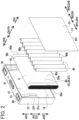
- FIG. 2 is an exploded perspective view of the battery 1.
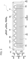
- FIG. 3 is a cross-sectional view of the battery 1.
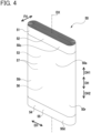
- FIG. 4 is a perspective view of an electrode body 50.
- a case height direction AH, a case width direction BH, and a case thickness direction CH are defined as directions indicated in FIGs. 1 to 3 .
- An electrode body axial direction DH, an electrode body width direction EH, and an electrode body thickness direction FH are defined as directions indicated in FIGs. 1 to 4 .
- the battery 1 is a rectangular, more specifically, rectangular parallelepiped sealed lithium-ion secondary battery which will be installed in vehicles such as a hybrid car, a plug-in hybrid car, and an electric automobile.
- the battery 1 is configured with a case 10, a flat wound electrode body 50 housed in the case 10, a positive terminal (an electrode terminal) 60 and a negative terminal (another electrode terminal) 70 each supported by the case 10, and others.
- the electrode body 50 is covered with a not-shown bag-shaped insulating holder formed of an insulating film in the case 10.
- the case 10 contains an elastic interposing member 40 overlapped with the electrode body 50 (see FIGs. 2 and 3 but not shown in in FIG. 1 ).
- the case 10 furthermore contains an electrolytic solution 3, a part of which is impregnated in the electrode body 50 and the remainder of which is accumulated on a second side wall portion 14 as a lower wall portion of the case 10.
- the case 10 is made of metal (e.g., aluminum in the first embodiment). Alternatively, the case 10 may be formed of stainless steel.
- This case 10 has a parallelepiped box-like shape and includes a first primary wall portion 11, a second primary wall portion 12, and four side wall portions 13 to 16 (specifically, a first side wall portion 13, a second side wall portion 14, a third side wall portion 15, and a fourth side wall portion 16), each of which is of a rectangular plate-like shape.
- the first primary wall portion 11 and the second primary wall portion 12 have wider area than the side wall portions 13 to 16.
- the first primary wall portion 11 and the second primary wall portion 12 oppose to each other.
- the first primary wall portion 11 is positioned on one side CH1 (specifically, a right forward side in FIGs. 1 and 2 and an upper side in FIG. 3 ) of the case thickness direction CH
- the second primary wall portion 12 is positioned on another side CH2 (specifically, a left rear side in FIGs. 1 and 2 and a lower side in FIG. 3 ) of the case thickness direction CH.
- the side wall portions 13 to 16 each join the first primary wall portion 11 and the second primary wall portion 12 and extend in the case thickness direction CH.
- the first side wall portion 13 and the second side wall portion 14 oppose to each other in a manner that the first side wall portion 13 is positioned on an upper side AH1 in the case height direction AH and the second side wall portion 14 is positioned on a lower side AH2 in the case height direction AH.
- the third side wall portion 15 and the fourth side wall portion 16 oppose to each other in a manner that the third side wall portion 15 is positioned on one side BH1 in the case width direction BH, and that the fourth side wall portion 16 is positioned on another side BH2 in the case width direction BH.
- a safety valve 17 is provided in the first side wall portion 13 as an upper wall portion of the case 10 and will break and open when an internal pressure of the case 10 exceeds a valve opening pressure. Further, a liquid inlet 13k for communication between inside and outside of the case 10 is provided in the first side wall portion 13 and is hermetically sealed by a disc-shaped sealing member 18 made of aluminum. Herein, the liquid inlet 13k is used for injecting the electrolytic solution 3 in the case 10 in a process of producing the battery 1 as explained below.
- the positive terminal 60 is fixed to a vicinity of an end portion on the one side BH1 in the case width direction BH.
- the positive terminal 60 is formed by swaging and connecting a plurality of aluminum-made metal components and fixed to the first side wall portion 13 in a state insulated from the first side wall portion 13 via a resin portion 65 formed of a plurality of resin members.
- This positive terminal 60 is connected and conducted with a positive current collecting portion 50c of the electrode body 50 in the case 10, and also penetrates through the first side wall portion 13 to extend outside the case 10.
- a negative terminal 70 is fixed to a vicinity of an end portion on the another side BH2 in the case width direction BH.
- the negative terminal 70 is formed by swaging and connecting a plurality of copper-made metal components and fixed to the first side wall portion 13 in a state insulated from the first side wall portion 13 via a resin portion 75 formed of a plurality of resin members.
- the negative terminal 70 is connected and conducted with a negative current collecting portion 50d of the electrode body 50 in the case 10, and also penetrates through the first side wall portion 13 to extend outside the case 10.
- the case 10 is configured with a case body 21 of a bottomed rectangular cylindrical shape having a rectangular opening 21c and a lid 31 of a rectangular plate-like shape.
- the case body 21 constitutes the second primary wall portion 12 and the four side wall portions 13 to 16, and the opening 21c of the case body 21 is formed by the four side wall portions 13 to 16.
- the lid 31 constitutes the first primary wall portion 11 to close the opening 21c of the case body 21.
- a lid peripheral edge portion 31f of the lid 31 is joined or welded to an opening peripheral edge portion 21f of the opening 21c of the case body 21 over an entire circumference.
- This electrode body 50 is formed in such a manner that a strip-shaped positive electrode plate (one example of an electrode plate) 51 and a strip-shaped negative electrode plate (another example of the electrode plate) 54 are overlapped via a pair of strip-shaped separators 57 formed of resin-made porous films, and the thus overlapped electrode plates 51,54 and the separators 57 are wound around a winding axis DX into a cylindrical shape and then pressed into a flat shape.
- the electrode body 50 includes a pair of electrode round portions 50r positioned on both end portions in the electrode body width direction EH and an electrode laminated portion 50e held between the pair of the electrode round portions 50r.
- Each of the electrode round portions 50r is a portion in which the positive electrode plate 51, the negative electrode plate 54, and the separators 57 are bent into a semi-cylindrical shape and overlapped.
- the electrode laminated portion 50e is a parallelepiped portion in which the positive electrode plate 51, the negative electrode plate 54, and the separators 57 are laminated in a flat-plate like shape in the electrode body thickness direction FH.
- the electrode body 50 has a positive current collecting portion 50c explained later on an end portion on one side DH1 in the electrode body axial direction DH along the winding axis DX and a negative current collecting portion 50d explained later on an end portion on another side DH2 in the electrode body axial direction DH.
- This electrode body 50 is housed in the case 10 in such a position that the electrode body axial direction DH is in parallel to the case width direction BH, the electrode body width direction EH is in parallel to the case height direction AH, and the electrode body thickness direction FH is in parallel to the case thickness direction CH. Further, the electrode body 50 is housed in the case 10 while the electrode laminated portion 50e is compressed in the electrode body thickness direction FH (i.e., in the case thickness direction CH).
- the battery 1 is a battery of a self-compression type in which the case 10 is elastically deformed to elastically compress the electrode laminated portion 50e of the electrode body 50 in the electrode body thickness direction FH by the first primary wall portion 11 and the second primary wall portion 12 of the case 10.
- the positive electrode plate 51 includes a positive current collecting foil 52 formed of a strip-shaped aluminum foil. Both primary surfaces of the positive current collecting foil 52 are each formed with a positive active material layer 53 of a strip shape including positive active material particles that can occlude and discharge lithium ions.
- a positive current collecting foil 52 formed of a strip-shaped aluminum foil. Both primary surfaces of the positive current collecting foil 52 are each formed with a positive active material layer 53 of a strip shape including positive active material particles that can occlude and discharge lithium ions.
- one end portion in the width direction has no positive active material layer 53 on the positive current collecting foil 52, and the positive current collecting foil 52 is exposed. This exposed portion of the positive current collecting foil 52 spirally protrudes to the one side DH1 in the electrode body axial direction DH from the electrode laminated portion 50e in the electrode body 50 to form the above-mentioned positive current collecting portion 50c.
- the positive current collecting portion 50c is connected to the positive terminal 60.
- the negative electrode plate 54 includes a negative current collecting foil 55 formed of a strip-shaped copper foil. Both primary surfaces of the negative current collecting foil 55 are each formed with a negative active material layer 56 of a strip shape including negative active material particles that can occlude and discharge lithium ions.
- a negative active material layer 56 of a strip shape including negative active material particles that can occlude and discharge lithium ions.
- one end portion in the width direction has no negative active material layer 56 on the negative current collecting foil 55, and the negative current collecting foil 55 is exposed.
- This exposed portion of the negative current collecting foil 55 spirally protrudes to the another side DH2 in the electrode body axial direction DH from the electrode laminated portion 50e in the electrode body 50 to form the above-mentioned negative current collecting portion 50d.
- the negative current collecting portion 50d is connected to the negative terminal 70.
- the elastic interposing member 40 is interposed between the first primary wall portion 11 of the case 10 and the electrode laminated portion 50e of the electrode body 50.
- This elastic interposing member 40 is made of metal, specifically, aluminum in the first embodiment.
- the elastic interposing member 40 may be alternatively made of stainless steel.
- the elastic interposing member 40 is a corrugated plate having a rectangular shape in planar view.
- the elastic interposing member 40 has a configuration in which a plurality of inner semi-cylindrical portions 40a of semi-cylindrical shapes and a plurality of outer semi-cylindrical portions 40b of semi-cylindrical shapes are alternately arranged and connected in the case width direction BH.
- Each of the inner semi-cylindrical portions 40a protrudes toward an inner side CH3 in the case thickness direction CH, namely, toward the electrode laminated portion 50e, and extends to the case height direction AH.
- each of the outer semi-cylindrical portions 40b protrudes toward an outer side CH4 in the case thickness direction CH, namely, toward the first primary wall portion 11, and extends to the case height direction AH.
- This elastic interposing member 40 is elastically deformed in the case thickness direction CH to press the electrode laminated portion 50e of the electrode body 50 in the electrode body thickness direction FH.
- the electrode laminated portion 50e of the electrode body 50 is elastically compressed in the electrode body thickness direction FH by the first primary wall portion 11 and the second primary wall portion 12 of the case 10.
- this battery 1 is a self-compression type in which the battery 1 itself elastically compresses the electrode laminated portion 50e of the electrode body 50. Accordingly, in use of the battery 1, a binding member does not have to be separately prepared, or outer binding by a simple binding member is enough.
- the battery 1 is formed by joining the case body 21 constituting the second primary wall portion 12 and the four side wall portions 13 to 16 with the lid 31 constituting the first primary wall portion 11, and thus the battery 1 of the self-compression type can be easily produced and the battery 1 can be inexpensive as explained below.
- the elastic interposing member 40 is interposed between the first primary wall portion 11 of the case 10 and the electrode laminated portion 50e of the electrode body 50 so that the electrode laminated portion 50e is pressed by elastic deformation of the case 10 and the elastic interposing member 40.
- the elastic interposing member 40 is a corrugated plate and can easily change its elasticity coefficient by changing a plate thickness or changing pitches. Accordingly, providing the elastic interposing member 40 can achieve the battery 1 in which the electrode laminated portion 50e is pressed by a more appropriate pressing force.
- the elastic interposing member 40 is made of aluminum, and thus the battery 1 can be a battery in which the electrode laminated portion 50e is pressed by the appropriate pressing force.
- the positive terminal 60 and the negative terminal 70 are fixed not to the first primary wall portion 11 or the second primary wall portion 12 of the case 10 but to the first side wall portion 13. Accordingly, when a battery module is to be formed by stacking a plurality of the batteries 1 in the case thickness direction CH, the positive terminal 60 and the negative terminal 70 of the adjacent batteries 1 can be easily connected by use of a bus bar or the like.
- the liquid inlet 13k is provided in the first side wall portion 13 of the case 10. Accordingly, as mentioned below, injection can be easily performed when the battery 1 is placed in such a position that the first side wall portion 13 faces the upper side AH1 and the second side wall portion 14 faces the lower side AH2 in performing injection of the electrolytic solution 3.
- the electrode body 50 wrapped with the insulating holder and the elastic interposing member 40 are housed in the case body 21, in which the positive terminal 60 and the negative terminal 70 have been fixed to the first side wall portion 13 in advance, in a manner that the elastic interposing member 40 is overlapped on the electrode body 50 (see FIG. 6 ).
- the case body 21 is placed on a flat setting table 510 of a press device 500 in such a position that the entire second primary wall portion 12 of the case body 21 comes to contact with the setting table 510.
- the electrode body 50 is housed in the case body 21 in such a position that the electrode body axial direction DH is in parallel to the case width direction BH, the electrode body width direction EH is in parallel to the case height direction AH, and the electrode body thickness direction FH is in parallel to the case thickness direction CH. Further, the elastic interposing member 40 is overlapped on the electrode laminated portion 50e of the electrode body 50. Thereafter, the positive current collecting portion 50c of the electrode body 50 and the positive terminal 60 fixed to the case body 21 are connected by laser welding. Further, the negative current collecting portion 50d of the electrode body 50 and the negative terminal 70 fixed to the case body 21 are connected by laser welding.
- a "pressing and compressing step S2" (see FIG. 5 )
- the lid 31 is placed over the electrode body 50 and the elastic interposing member 40 which are housed in the case body 21.
- An external force Fa is applied to the first primary wall portion 11 constituted by the lid 31 and to the second primary wall portion 12 of the case body 21 to press and compress the electrode laminated portion 50e of the electrode body 50 and the elastic interposing member 40 in the electrode body thickness direction FH (see FIG. 7 ).
- a press part 520 of the press device 500 is brought into contact with the first primary wall portion 11 constituted by the lid 31 to apply the external force Fa to the first primary wall portion 11 and the second primary wall portion 12 by holding the lid 31 and the case body 21 between the press part 520 and the setting table 510. Then, the electrode laminated portion 50e of the electrode body 50 and the elastic interposing member 40 are each pressed and compressed in the electrode body thickness direction FH so that the lid peripheral edge portion 31f of the lid 31 is entirely brought into contact with the opening peripheral edge portion 21f of the opening 21c of the case body 21 (see FIG. 8 ).
- the lid peripheral edge portion 31f of the lid 31 is joined to the opening peripheral edge portion 21f of the case body 21 over the entire circumference to form the case 10 (see FIG. 8 ).
- the laser beam LB is irradiated on the lid peripheral edge portion 31f and the opening peripheral edge portion 21f for laser welding, and thus the lid peripheral edge portion 31f and the opening peripheral edge portion 21f are entirely joined.
- a "releasing step S4" (see FIG. 5 ), the above-mentioned external force Fa is released. Namely, the press part 520 of the press device 500 is moved away from the lid 31 to release the external force Fa. At that time, the case 10 has already been formed in the joining step S3, and thus the compressed electrode laminated portion 50e and the elastic interposing member 40 do not return to their original state (i.e., original thickness). After releasing the external force Fa, the electrode laminated portion 50e is in an elastically compressed state by the first primary wall portion 11 and the second primary wall portion 12 of the case 10.
- the electrolytic solution 3 is injected into the case 10 through the liquid inlet 13k so that the electrolytic solution 3 is impregnated in the electrode body 50.
- the battery 1 is placed in such a position that the first side wall portion 13 provided with the liquid inlet 13k is on the upper side AH1 and the second side wall portion 14 is on the lower side AH2 (see FIG. 1 ).
- an injection nozzle of an injection device (not shown) is inserted in the liquid inlet 13k of the battery 1 from the upper side AH1 to inject the electrolytic solution 3 of a predetermined amount into the case 10.
- the electrolytic solution 3 is impregnated in the electrode body 50 for a predetermined period of time.
- the liquid inlet 13k is covered by the sealing member 18 from outside and the sealing member 18 is laser-welded to the case 10 to hermetically seal the sealing member 18 with the case 10.
- a charging device (not shown) is connected to the battery 1 to perform initial charging to the battery 1. Thereafter, the initially charged battery 1 is left stand for a predetermined time for aging. Thus, the battery 1 is completed.
- a case 10 is configured by a bottomed rectangular cylindrical case body constituting a first primary wall portion 11, a second primary wall portion 12, and three side wall portions (specifically, a second side wall portion 14, a third side wall portion 15, and a fourth side wall portion 16) and a lid constituting a first side wall portion 13.
- a space between the first primary wall portion 11 and the second primary wall portion 12 of the case body is made to be narrower than a total thickness of the electrode body 50 and the elastic interposing member 40 in order to press and compress the electrode laminated portion 50e of the electrode body 50 in a post-assembled battery. Accordingly, the electrode body 50 and the elastic interposing member 40 are difficult to be inserted in the case body.
- the electrode body 50 and the elastic interposing member 40 are housed in the bottomed rectangular cylindrical case body 21 constituting the second primary wall portion 12 and the four side wall portions 13 to 16 in the housing step S1 (see FIG. 6 ), so that the electrode body 50 and the elastic interposing member 40 can be easily housed in the case body 21.
- the battery 1 of the self-compression type in which the battery 1 itself elastically compresses the electrode laminated portion 50e of the electrode body 50, can be easily produced.
- the elastic interposing member 40 is used for producing the battery 1, and thus the battery 1 can be produced in such a manner that the electrode laminated portion 50e of the electrode body 50 is pressed with a further appropriate pressing force. Further, the elastic interposing member 40 made of aluminum is used, and thus the battery 1 can be produced in such a manner that the electrode laminated portion 50e is pressed with the appropriate pressing force.
- the electrode body 50 in the housing step S1, the electrode body 50 is housed in the case body 21 in which the positive terminal 60 and the negative terminal 70 have been fixed to the first side wall portion 13 in advance, and then the positive terminal 60 and the negative terminal 70 are connected to the electrode body 50. Accordingly, housing of the electrode body 50 in the case body 21 and connection of the electrode body 50 with the positive terminal 60 and the negative terminal 70 can be performed easily.
- the liquid inlet 13k is provided in the first side wall portion 13, and therefore, injection of the electrolytic solution 3 can be performed easily in a manner that the battery 1 is positioned with the first side wall portion 13 facing the upper side AH1 and the second side wall portion 14 facing the lower side AH2.
- the elastic interposing member 40 is placed between the first primary wall portion 11 of the case 10 and the electrode laminated portion 50e of the electrode body 50.
- a battery (a power storage device) 100 of the second embodiment there is no elastic interposing member placed between a first primary wall portion 111 of a case 110 and the electrode laminated portion 50e of the electrode body 50 and between a second primary wall portion 12 of the case 110 and the electrode laminated portion 50e of the electrode body 50.
- the first primary wall portion 11 i.e., the lid 31
- the first primary wall portion 111 i.e., a lid 131
- the case 110 in the second embodiment is not of a plate-like shape but includes an elastically deforming portion 111e, which is different from the first embodiment.
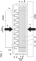
- the first primary wall portion 111 in the second embodiment has the elastically deforming portion 111e that is to be elastically deformed in the case thickness direction CH as a center portion of a rectangular shape in planar view (i.e., a rectangular shape when seen from the case thickness direction CH) other than a peripheral portion 111s.
- This elastically deforming portion 111e protrudes toward the inner side CH3 of the case thickness direction CH more inward than the peripheral portion 111s of the first primary wall portion 111, namely toward the electrode laminated portion 50e.
- the elastically deforming portion 111e includes a plurality of semi-cylindrical portions 111ea of semi-cylindrical shapes extending in the case height direction AH (namely, a direction orthogonal to a sheet surface in FIG. 9 ) and linking to one another in the case width direction BH.
- the elastically deforming portion 111e is to be elastically deformed to press the electrode laminated portion 50e of the electrode body 50 in the electrode body thickness direction FH.
- the battery 100 of the second embodiment is formed by housing the electrode body 50 in the case 110 in such a manner that the electrode laminated portion 50e of the electrode body 50 is compressed in the electrode body thickness direction FH.
- the elastically deforming portion 11 1e of the first primary wall portion 111 is mainly elastically deformed to elastically compress the electrode laminated portion 50e of the electrode body 50 in the electrode body thickness direction FH by the first primary wall portion 111 and the second primary wall portion 12 of the case 110.
- the battery 100 of the second embodiment is also a self-compression type of elastically compressing the electrode laminated portion 50e of the electrode body 50 by the battery 100 itself. Therefore, in use of the battery 100, any binding members do not need to be separately prepared, or outside binding by a simple binding member is enough.
- the case 110 is formed by joining the case body 21 constituting the second primary wall portion 12 and the four side wall portions 13 to 16 with the lid 131 constituting the first primary wall portion 111, and therefore, the battery 100 of the self-compression type can be easily produced and the battery 100 can be inexpensive.
- the first primary wall portion 111 of the case 110 includes the elastically deforming portion 111e which is elastically deformed in the case thickness direction CH, and thus the battery 100 can achieve pressing of the electrode laminated portion 50e of the electrode body 50 by a further appropriate pressing force.
- the case 110 having the elastically deforming portions 11 1e is made of aluminum, and thus the battery 100 can achieve pressing of the electrode laminated portion 50e by the appropriate pressing force.
- the electrode body 50 wrapped with the insulating holder is housed in the case body 21 in which the positive terminal 60 and the negative terminal 70 are fixed.
- the positive current collecting portion 50c and the negative current collecting portion 50d of the electrode body 50 are laser welded to the positive terminal 60 and the negative terminal 70 which are fixed to the case body 21, respectively.
- the lid 131 is placed over the electrode body 50 housed in the case body 21.
- the external force Fa is applied to the first primary wall portion 111 constituted by the lid 131 and the second primary wall portion 12 of the case body 21 to elastically deform the elastically deforming portion 111e of the first primary wall portion 111 in the case thickness direction CH and to press and compress the electrode laminated portion 50e of the electrode body 50 in the electrode body thickness direction FH.
- the lid peripheral edge portion 131f of the lid 131 is brought into contact with the opening peripheral edge portion 21f of the case body 21 over an entire circumference.
- This step is performed by the press device 500 (see FIG. 7 ) similar to the first embodiment.
- the lid peripheral edge portion 131f of the lid 131 is entirely laser welded to the opening peripheral edge portion 21f of the case body 21 to form the case 10.
- the releasing step S4 the injecting step S5, the sealing step S6, and the initial charging and aging step S7 are performed to complete the battery 100.
- the electrode body 50 is housed in the bottomed rectangular cylindrical case body 21 constituting the second primary wall portion 12 and the four side wall portions 13 to 16 in the housing step S1, so that housing of the electrode body 50 in the case body 21 can be easily performed. Thereafter, by performing the pressing and compressing step S2, the joining step S3, and the releasing step S4, the battery 100 of the self-compression type can be easily produced.
- the first primary wall portion 111 of the case 110 has the elastically deforming portion 111e which is elastically deformed in the case thickness direction CH.
- the battery 100 can be thus produced in such a manner that the electrode laminated portion 50e of the electrode body 50 is pressed by the further appropriate pressing force.
- the aluminum-made case 110 having the elastically deforming portions 111e is used, and thus the battery 100 can be produced with the electrode laminated portion 50e pressed with the appropriate pressing force.
- a third embodiment is explained (see FIG. 10 ).
- the parts similar to the first embodiment or the second embodiment is omitted or simplified with their explanation.
- a first primary wall portion 211 i.e., a lid 231
- a configuration of the elastically deforming portion 211e is different from that of the elastically deforming portion 111e of the second embodiment.
- the third embodiment is different from the first and second embodiments in a manner that a second primary wall portion 212 of the case 210 is also provided with an elastically deforming portion 212e.
- the first primary wall portion 211 of the third embodiment has a center portion of a rectangular shape in planar view other than its peripheral portion 211s as the elastically deforming portion 211e to be elastically deformed in the case thickness direction CH.
- the elastically deforming portion 211e protrudes toward the inner side CH 3 in the case thickness direction CH (namely, toward the electrode laminated portion 50e) more inward than the peripheral portion 211s of the first primary wall portion 211, and a plurality of protruding ridge portions 211ea of U-shape in section extending in the case height direction AH (in FIG.
- the elastically deforming portion 211e is elastically deformed in the case thickness direction CH to press the electrode laminated portion 50e of the electrode body 50 in the electrode body thickness direction FH.
- the second primary wall portion 212 also has a center portion of a rectangular shape in planar view other than its peripheral portion 212s as an elastically deforming portion 212e to be elastically deformed in the case thickness direction CH.
- This elastically deforming portion 212e protrudes toward the inner side CH3 in the case thickness direction CH (namely, toward the electrode laminated portion 50e) more inward than the peripheral portion 212s of the second primary wall portion 212, and a plurality of protruding ridge portions 212ea of U-shape in section extending in the case height direction AH are formed to be adjoined but spaced from one another in a stripe pattern in the case width direction BH.
- the elastically deforming portion 212e is elastically deformed in the case thickness direction CH to press the electrode laminated portion 50e of the electrode body 50 in the electrode body thickness direction FH.
- the battery 200 of the third embodiment is also formed by housing the electrode body 50 in the case 210 in such a manner that the electrode laminated portion 50e of the electrode body 50 is compressed in the electrode body thickness direction FH.
- the elastically deforming portion 211e of the first primary wall portion 211 and the elastically deforming portion 212e of the second primary wall portion 212 are mainly elastically deformed to elastically compress the electrode laminated portion 50e of the electrode body 50 in the electrode body thickness direction FH by the first primary wall portion 211 and the second primary wall portion 212 of the case 210.
- the battery 200 of the third embodiment is also the self-compression type of elastically compressing the electrode laminated portion 50e of the electrode body 50 by the battery 200 itself. Therefore, in use of the battery 200, any binding members do not need to be separately prepared, or outside binding by a simple binding member is enough.
- the case 210 is formed by joining the case body 221 constituting the second primary wall portion 212 and the four side wall portions 13 to 16 with the lid 231 constituting the first primary wall portion 211, and therefore, the battery 200 of the self-compression type can be easily produced, and the battery 200 can be inexpensive.
- first primary wall portion 211 of the case 210 is provided with the above-mentioned elastically deforming portion 211e
- the second primary wall portion 212 is provided with the above-mentioned elastically deforming portion 212e, so that the battery 200 can be produced in such a manner that the electrode laminated portion 50e of the electrode body 50 is pressed with the further appropriate pressing force.
- the battery 200 of the third embodiment is produced as similar to the battery 100 of the second embodiment.
- the electrode body 50 is housed in the case body 221 in the housing step S1, and in the pressing and compressing step S2, the external force Fa is applied to the first primary wall portion 211 and the second primary wall portion 212 by the press device 500 to press and compress the electrode laminated portion 50e of the electrode body 50 in the electrode body thickness direction FH while the elastically deforming portions 211e and 212e are elastically deformed in the case thickness direction CH.
- the lid peripheral edge portion 23 If of the lid 231 is laser welded to the opening peripheral edge portion 221f of the opening 21c of the case body 21 over an entire circumference to form the case 210.
- the external force Fa is released in the releasing step S4.
- the injecting step S5, the sealing step S6, and the initial charging and aging step S7 are performed to complete the battery 200.
- the electrode body 50 is housed in the bottomed rectangular cylindrical case body 221 constituting the second primary wall portion 212 and the four side wall portions 13 to 16 in the housing step S1, so that the electrode body 50 can be easily housed in the case body 221. Thereafter, by performing the pressing and compressing step S2, the joining step S3, and the releasing step S4, the battery 200 of the self-compression type can be easily produced. Further, the first primary wall portion 211 of the case 210 has the elastically deforming portion 211e, and the second primary wall portion 212 has the elastically deforming portion 212e, and thus the battery 200 can be produced with the electrode laminated portion 50e of the electrode body 50 pressed by the further appropriate pressing force.
- a fourth embodiment is explained (see FIG. 11 ). Explanations for the same parts with the first to third embodiments are omitted or simplified.
- a first primary wall portion 311 i.e., a lid 331
- a second primary wall portion 312 is provided with an elastically deforming portion 312e in a case 310. Configuration of these elastically deforming portions 311e and 312e is different from those of the elastically deforming portions 111e, 211e, and 212e in the second and third embodiments.
- the first primary wall portion 311 of the fourth embodiment has a center portion of a rectangular shape in planar view other than its peripheral portion 311s as the elastically deforming portion 311e to be elastically deformed in the case thickness direction CH.
- This elastically deforming portion 311e is a protruding portion of a rectangular shape in planar view, entirely protruding toward the inner side CH3 (namely, toward the electrode laminated portion 50e) in the case thickness direction CH.
- the elastically deforming portion 311e is elastically deformed in the case thickness direction CH to press the electrode laminated portion 50e of the electrode body 50 in the electrode body thickness direction FH.
- the second primary wall portion 312 has a center portion of a rectangular shape in planar view other than its peripheral portion 312s as the elastically deforming portion 312e to be elastically deformed in the case thickness direction CH.
- This elastically deforming portion 312e is also a protruding portion of a rectangular shape in planar view, entirely protruding toward the inner side CH3 (namely, toward the electrode laminated portion 50e) in the case thickness direction CH.
- the elastically deforming portion 312e is elastically deformed in the case thickness direction CH to press the electrode laminated portion 50e of the electrode body 50 in the electrode body thickness direction FH.
- the battery 300 of the fourth embodiment is also formed by housing the electrode body 50 in the case 310 in such a manner that the electrode laminated portion 50e of the electrode body 50 is compressed in the electrode body thickness direction FH.
- the elastically deforming portion 311e of the first primary wall portion 311 and the elastically deforming portion 312e of the second primary wall portion 312 are mainly elastically deformed in the case thickness direction CH to elastically compress the electrode laminated portion 50e of the electrode body 50 in the electrode body thickness direction FH by the first primary wall portion 311 and the second primary wall portion 312 of the case 310.
- the battery 300 of the fourth embodiment is also the self-compression type of elastically compressing the electrode laminated portion 50e of the electrode body 50 by the battery 300 itself. Therefore, in use of the battery 300, any binding members do not need to be separately prepared, or outside binding by a simple binding member is enough.
- the case 310 is formed by joining the case body 321 constituting the second primary wall portion 312 and the four side wall portions 13 to 16 with the lid 331 constituting the first primary wall portion 311, and therefore, the battery 300 of the self-compression type can be easily produced, and the battery 300 can be inexpensive.
- the battery 300 of the fourth embodiment is produced as similar to the battery 100 of the second embodiment and the battery 200 of the third embodiment.
- the electrode body 50 is housed in the case body 321 in the housing step S1, and in the pressing and compressing step S2, the external force Fa is applied to the first primary wall portion 311 and the second primary wall portion 312 by the press device 500 to press and compress the electrode laminated portion 50e of the electrode body 50 in the electrode body thickness direction FH while the elastically deforming portions 311e and the 312e are elastically deformed in the case thickness direction CH.
- the lid peripheral edge portion 331f of the lid 331 is laser welded to the opening peripheral edge portion 321f of the opening 321c of the case body 321 over an entire circumference to form the case 310.
- the external force Fa is released in the releasing step S4.
- the injecting step S5, the sealing step S6, and the initial charging and aging step S7 are performed to complete the battery 300.
- the electrode body 50 is housed in the bottomed rectangular cylindrical case body 321 constituting the second primary wall portion 312 and the four side wall portions 13 to 16 in the housing step S1, so that the electrode body 50 can be easily housed in the case body 321. Thereafter, by performing the pressing and compressing step S2, the joining step S3, and the releasing step S4, the battery 300 of the self-compression type can be easily produced.
- the flat-wound electrode body 50 is illustrated as an example of the electrode body, but the electrode body is not limited to a flat-wound type.
- the electrode body may be a laminated electrode body in which a plurality of rectangular positive electrode plates (electrode plates) and a plurality of rectangular negative electrode plates (electrode plate) are laminated via a rectangular separator, respectively.
Landscapes
- Chemical & Material Sciences (AREA)
- Chemical Kinetics & Catalysis (AREA)
- Electrochemistry (AREA)
- General Chemical & Material Sciences (AREA)
- Engineering & Computer Science (AREA)
- Manufacturing & Machinery (AREA)
- Inorganic Chemistry (AREA)
- Materials Engineering (AREA)
- Sealing Battery Cases Or Jackets (AREA)
- Secondary Cells (AREA)
- Connection Of Batteries Or Terminals (AREA)
- Electric Double-Layer Capacitors Or The Like (AREA)
- Cell Separators (AREA)
- Filling, Topping-Up Batteries (AREA)
Abstract
A power storage device (1) is provided with a parallelepiped box-like case (10) and an electrode body (50) housed in the case (10). The case (10) includes a bottomed rectangular cylindrical case body (21) having a rectangular opening (21c) and forming a second primary wall portion (12) and four side wall portions (13, 14, 15, 16), and a rectangular lid (31) forming a first primary wall portion (11), in which a lid peripheral edge portion (31f) is joined to an opening peripheral edge portion (21f) of the opening (21c) of the case body (21) over an entire circumference. The first primary wall portion (11) and the second primary wall portion (12) of the case (10) elastically compress an electrode laminated portion (50e) of the electrode body (50) in an electrode body thickness direction (FH).
Description
- The present disclosure relates to a rectangular power storage device in which an electrode body is housed in a rectangular parallelepiped box-like case and a method for producing the power storage device.
- Among rectangular batteries in each of which an electrode body is housed in a rectangular parallelepiped box-like case, particularly, a battery mounted on a vehicle and the like for long time use is generally formed with external binding by use of an external binding member formed of a pair of end plates and a plurality of binding bands for the purpose of improving the characteristics of charge and discharge cycles and others. As a result of this, an electrode laminated portion of an electrode body housed in the case is in a state pressed in an electrode body thickness direction. Related prior arts include Patent Document 1 (see
FIG. 1 and others of the Patent Document 1), for example. - Patent Document 1:
JP2020-173893A - However, binding a battery from outside with a binding member causes problems such as increase in cost, increase in a frame size, increase in weight, increase in the number of components, and others.
- The present disclosure has been made in view of the above circumstances and has a purpose of providing a power storage device achieving elastic compression of an electrode laminated portion of an electrode body in an electrode body thickness direction by the power storage device itself and also has a purpose of providing a method for producing the power storage device.
-
- (1) One aspect of the present disclosure to solve the above problem is to provide a power storage device comprising: a case; and an electrode body housed in the case, the case of a parallelepiped box-like shape including: a first primary wall portion of a rectangular shape; a second primary wall portion of a rectangular shape opposing to the first primary wall portion; and four side wall portions, each of which is of a rectangular shape, connects the first primary wall portion and the second primary wall portion, and extends in a case thickness direction, the electrode body including electrode plates and an electrode laminated portion of a parallelepiped shape in which the electrode plates are laminated in an electrode body thickness direction, and the electrode body being housed in the case in such a position that the electrode body thickness direction is in parallel to the case thickness direction, wherein the case includes: a case body of a bottomed rectangular cylindrical shape configuring the second primary wall portion and the four side wall portions and being formed with an opening of a rectangular shape configured by the four side wall portions; and a lid of a rectangular shape configuring the first primary wall portion in which a lid peripheral edge portion is joined to an entire circumference of an opening peripheral edge portion of the opening of the case body, and the first primary wall portion and the second primary wall portion of the case elastically compress the electrode laminated portion of the electrode body in the electrode body thickness direction.
- The above-mentioned power storage device is configured such that the first primary wall portion and the second primary wall portion of the case elastically compress the electrode laminated portion of the electrode body in the electrode body thickness direction. In other words, this power storage device is of a self-compression type that elastically compresses the electrode laminated portion of the electrode body by the power storage device itself. Accordingly, no binding member needs to be separately prepared, or external binding by a simple binding member is enough in use of the power storage device.
- Further, the above-mentioned power storage device is formed by joining the case body configuring the second primary wall portion and the four side wall portions to the lid configuring the first primary wall portion, and thus a power storage device of a self-compression type can be easily produced as mentioned below and the power storage device can be inexpensive.
- Further, as the "power storage device", for example, secondary batteries such as a lithium-ion secondary battery, capacitors such as a lithium ion capacitor, and all-solid-state batteries can be exemplified.
- Further, in the above-mentioned power storage device, an interposing member, which is made of metal or resin and formed of a flat plate or a corrugated plate, may be interposed between the first primary wall portion of the case and the electrode laminated portion of the electrode body or between the second primary wall portion of the case and the electrode laminated portion of the electrode body.
- (2) Further, in the power storage device in the above (1), preferably, an elastic interposing member is provided to be elastically deformed in the case thickness direction to press the electrode laminated portion in the electrode body thickness direction in any one of between the first primary wall portion of the case and the electrode laminated portion of the electrode body and between the second primary wall portion of the case and the electrode laminated portion of the electrode body.
- In the above-mentioned power storage device, the elastic interposing member is interposed between the first primary wall portion of the case and the electrode laminated portion of the electrode body or between the second primary wall portion of the case and the electrode laminated portion of the electrode body, and the electrode laminated portion is pressed by elastic deformation of the case and the elastic interposing member. The elasticity coefficient of the elastic interposing member is easily changed as compared to the elasticity coefficient of the case, and thus application of the elastic interposing member achieves a power storage device in which the electrode laminated portion is pressed by a more appropriate pressing force.
- Herein, as material for the "elastic interposing member", for example, metal such as aluminum, stainless steel, steel, copper, titanium, rubber, and plastic may be exemplified.
- (3) Further, the power storage device according to the above (2), preferably, the elastic interposing member is made of any one of aluminum and stainless steel.
- In the above-mentioned power storage device, the elastic interposing member is made of aluminum or stainless steel, and thus the power storage device, in which the electrode laminated portion is pressed by an appropriate pressing force, can be achieved.
- (4) Further, in the power storage device in the above (1), preferably, at least any one of the first primary wall portion and the second primary wall portion of the case is provided with an elastically deforming portion which is elastically deformed in the case thickness direction to press the electrode laminated portion of the electrode body in the electrode body thickness direction.
- In the above-mentioned power storage device, at least any one of the first primary wall portion and the second primary wall portion of the case includes the above-mentioned elastically deforming portion, and thus the power storage device in which the electrode laminated portion is pressed with the further appropriate pressing force can be achieved.
- Herein, as material for the "case including the elastically deforming portion", metal such as aluminum, stainless steel, steel, copper, titanium, and plastic may be exemplified.
- (5) Further, in the power storage device in the above (4), preferably, the case comprising the elastically deforming portion is made of any one of aluminum and stainless steel.
- In the above-mentioned power storage device, the case provided with the elastically deforming portion is made of aluminum or stainless steel, and thus the power storage device, in which the electrode laminated portion of the electrode body is pressed by the appropriate pressing force, can be achieved.
- (6) Further, the power storage device in any one of the above (1) to (5), preferably, an electrode terminal is connected to the electrode body in the case and penetrates through and extends outside the case, and the electrode terminal is fixed to any one of the side wall portions of the case.
- When a power storage module is formed by stacking a plurality of power storage devices in the case thickness direction, the first primary wall portion and the second primary wall portion of the adjacent power storage devices oppose to each other. Alternatively, the first primary wall portions of the adjacent power storage devices or the second primary wall portions of the adjacent power storage devices oppose to each other. Accordingly, in the power storage device in which the electrode terminal is fixed to the first primary wall portion or the second primary wall portion of the case, it is difficult to connect the electrode terminals of the adjacent power storage devices.
- To address this, in the above-mentioned power storage device, the electrode terminal is not fixed to the first primary wall portion or the second primary wall portion but fixed to the side wall portion. As a result of this, when the power storage module is formed by stacking a plurality of the power storage devices in the case thickness direction, the electrode terminals of the adjacent power storage devices can be easily joined by use of a bus bar and others.
- (7) Further, in the power storage device in any one of the above (1) to (6), preferably, an electrolytic solution housed in the case is provided, and a liquid inlet communicating inside and outside of the case to inject the electrolytic solution into the case is provided in any one of the side wall portions of the case.
- In a power storage device in which a liquid inlet of an electrolytic solution is provided in the first primary wall portion or the second primary wall portion, when the power storage device is placed in such a position that any one of the side wall portions of the case faces upward, the liquid inlet provided in the first primary wall portion or the second primary wall portion faces a horizontal direction. Thus, liquid injection of the electrolytic solution becomes difficult.
- To address this, in the above-mentioned power storage device, the liquid inlet is provided in the side wall portion of the case. Therefore, in injecting the electrolytic solution, the power storage device can achieve easy injection in such a manner that the power storage device is placed with the side wall portion provided with the liquid inlet facing upward.
- (8) Another aspect of the present disclosure is to provide a method for producing a power storage device comprising: a case; and an electrode body housed in the case; the case of a parallelepiped box-like shape including: a first primary wall portion of a rectangular shape; a second primary wall portion of a rectangular shape opposing to the first primary wall portion; and four side wall portions, each of which is of a rectangular shape, connects the first primary wall portion and the second primary wall portion, and extends in a case thickness direction, the electrode body including an electrode plate and an electrode laminated portion of a parallelepiped shape in which the electrode plates is laminated in an electrode body thickness direction, and the electrode body being housed in the case in such a position that the electrode body thickness direction is in parallel to the case thickness direction, wherein the case includes: a case body of a bottomed rectangular cylindrical shape configuring the second primary wall portion and the four side wall portions and being formed with an opening of a rectangular shape configured by the four side wall portions; and a lid of a rectangular shape configuring the first primary wall portion in which a lid peripheral edge portion is joined to an entire circumference of an opening peripheral edge portion of the opening of the case body, and the first primary wall portion and the second primary wall portion of the case elastically compress the electrode laminated portion of the electrode body in the electrode body thickness direction, wherein the method includes: housing the electrode body in the case body; pressing and compressing the electrode laminated portion of the electrode body in the electrode body thickness direction by placing the lid on the electrode body housed in the case body and applying an external force to the first primary wall portion configured by the lid and to the second primary wall portion of the case body; joining the lid peripheral edge portion of the lid to the opening peripheral edge portion of the opening portion of the case body over an entire circumference in a state in which the electrode body is pressed and compressed to form the case, and releasing the external force after the joining.
- In a conventional rectangular battery, a case is configured with a case body of a bottomed rectangular cylindrical shape constituting a first primary wall portion, a second primary wall portion, and three side wall portions of the case and configured with a lid constituting another side wall portion. The battery with such a configuration is difficult to be produced as a battery of a self-compression type. This is because a space between the first primary wall portion and the second primary wall portion of the case body is made narrower than a thickness of the electrode body or a sum of thicknesses of the electrode body and the interposing member in a battery provided with the above-mentioned interposing member for pressing and compressing the electrode laminated portion of the electrode body in the battery after assembling, so that the electrode body and the like is difficult to be inserted in the case body.
- On the other hand, in the above-mentioned method for producing the power storage device, the electrode body is firstly housed in the case body of the bottomed rectangular cylindrical shape constituting the second primary wall portion and the four side wall portions in a step of the housing, and thus the electrode body can be easily housed in the case body. After that, by the above-mentioned processes of the pressing and compressing, the joining, and the releasing, the self-compression-type power storage device which elastically compresses the electrode laminated portion of the electrode body by the power storage device itself can be easily produced.
- As a method of joining the lid to the case body in the process of "the joining", for example, joining by welding such as laser welding and joining by swaging may be adopted.
- (9) Further, in the method for producing the power storage device in the above (8), preferably, the power storage device is provided with an elastic interposing member to be elastically deformed in the case thickness direction to press the electrode laminated portion in the electrode body thickness direction in any one of between the first primary wall portion of the case and the electrode laminated portion of the electrode body and between the second primary wall portion of the case and the electrode laminated portion of the electrode body, the housing is to overlap the elastic interposing member on the electrode laminated portion of the electrode body and to house the electrode body and the elastic interposing member in the case body, and the pressing and compressing is to press and compress the electrode laminated portion of the electrode body and the elastic interposing member in the electrode body thickness direction.
- In the above-mentioned method for producing the power storage device, the power storage device is produced with the above-mentioned elastic interposing member, and thus the power storage device, in which the electrode laminated portion of the electrode body is pressed with a more appropriate pressing force, can be produced.
- (10) Further, in the method for producing the power storage device in the above (9), preferably, the elastic interposing member is made of any one of aluminum and stainless steel.
- In the above-mentioned method for producing the power storage device, the elastic interposing member made of aluminum or stainless steel is used, and thus the power storage device, in which the electrode laminated portion of the electrode body is pressed with the appropriate pressing force, can be produced.
- (11) In the method for producing the power storage device in the above (8), preferably, at least any one of the first primary wall portion and the second primary wall portion of the case is provided with an elastically deforming portion which is elastically deformed in the case thickness direction to press the electrode laminated portion of the electrode body in the electrode body thickness direction, and the pressing and compressing is to elastically deform the elastically deforming portion in the case thickness direction and pressing and compressing the electrode laminated portion of the electrode body in the electrode body thickness direction.
- In the above-mentioned method for producing the power storage device, at least any one of the first primary wall portion and the second primary wall portion of the case is provided with the above-mentioned elastically deforming portion, and thus the power storage device, in which the electrode laminated portion of the electrode body is pressed with the more appropriate pressing force, can be produced.
- (12) In the method for producing the power storage device in the above (11), preferably, the case comprising the elastically deforming portion is made of any one of aluminum and stainless steel.
- In the above-mentioned method for producing the power storage device, the case including the elastically deforming portion made of aluminum or stainless steel is used, and thus the power storage device, in which the electrode laminated portion of the electrode body is pressed with the appropriate pressing force, can be produced.
- (13) In the method for producing the power storage device in any one of the above (8) to (12), preferably, the power storage device is provided with an electrode terminal being connected to the electrode body in the case and penetrating through and extending outside the case, the electrode terminal is fixed to any one of the side wall portions of the case, and the housing is to house the electrode body in the case body in which the electrode terminal has been fixed to the one of the side wall portions in advance to connect the electrode terminal and the electrode body.
- In the above-mentioned method for producing the power storage device, in the process of the housing, the electrode body is housed in the case body in which the electrode terminal has been fixed to the side wall portion in advance to connect the electrode terminal and the electrode body. Accordingly, housing the electrode body in the case body and connecting the electrode terminal with the electrode body can be easily performed.
- (14) In the method for producing the power storage device in any one of the above (8) to (13), preferably, the power storage device is provided with: an electrolytic solution housed in the case, a liquid inlet communicating inside and outside of the case to inject the electrolytic solution into the case is provided in any one of the side wall portions of the case, the method includes injecting the electrolytic solution in the case through the liquid inlet after the releasing, and the injecting is performed in a state in which the side wall portion provided with the liquid inlet faces upward.
- In the above-mentioned method for producing the power storage device, the liquid inlet is provided in the side wall portion of the case. Accordingly, injection in the process of the injecting can be easily performed in such a manner that the power storage device is placed with the side wall portion provided with the liquid inlet facing upward in injecting the electrolytic solution.
-
-
FIG. 1 is a perspective view of a battery in a first embodiment; -
FIG. 2 is an exploded perspective view of the battery in the first embodiment; -
FIG. 3 is a cross-sectional view of the battery along a case width direction and a case thickness direction, taken along a line A-A inFIG. 1 in the first embodiment; -
FIG. 4 is a perspective view of an electrode body in the first embodiment; -
FIG. 5 is a flowchart showing a method of producing the battery in the first embodiment; -
FIG. 6 is an explanatory view illustrating a state in which the electrode body and an elastic interposing member are housed in a case body in a housing step in explaining the method of producing the battery in the first embodiment; -
FIG. 7 is an explanatory view illustrating a state in which an electrode laminated portion of the electrode body is pressed in an electrode body thickness direction by applying an external force in a pressing and compressing step in explaining the method of producing the battery in the first embodiment; -
FIG. 8 is an explanatory view illustrating a state in which a lid peripheral edge portion of a lid is laser welded to an opening peripheral edge portion of the case body in a joining step in explaining the method of producing the battery in the first embodiment; -
FIG. 9 is a cross-sectional view corresponding toFIG. 3 along a case width direction and a case thickness direction of a battery in a second embodiment; -
FIG. 10 is a cross-sectional view corresponding toFIG. 3 along a case width direction and a case thickness direction of a battery in a third embodiment; and -
FIG. 11 is a cross-sectional view corresponding toFIG. 3 along a case width direction and a case thickness direction of a battery in a fourth embodiment. - A first embodiment of the present disclosure is explained in detail below with reference to the accompanying drawings.
FIG. 1 is a perspective view of a battery (a power storage device) 1 in the first embodiment.FIG. 2 is an exploded perspective view of thebattery 1.FIG. 3 is a cross-sectional view of thebattery 1. Further,FIG. 4 is a perspective view of anelectrode body 50. In the following explanation, a case height direction AH, a case width direction BH, and a case thickness direction CH are defined as directions indicated inFIGs. 1 to 3 . An electrode body axial direction DH, an electrode body width direction EH, and an electrode body thickness direction FH are defined as directions indicated inFIGs. 1 to 4 . Thebattery 1 is a rectangular, more specifically, rectangular parallelepiped sealed lithium-ion secondary battery which will be installed in vehicles such as a hybrid car, a plug-in hybrid car, and an electric automobile. - The
battery 1 is configured with acase 10, a flatwound electrode body 50 housed in thecase 10, a positive terminal (an electrode terminal) 60 and a negative terminal (another electrode terminal) 70 each supported by thecase 10, and others. Theelectrode body 50 is covered with a not-shown bag-shaped insulating holder formed of an insulating film in thecase 10. Further, thecase 10 contains anelastic interposing member 40 overlapped with the electrode body 50 (seeFIGs. 2 and3 but not shown in inFIG. 1 ). Thecase 10 furthermore contains anelectrolytic solution 3, a part of which is impregnated in theelectrode body 50 and the remainder of which is accumulated on a secondside wall portion 14 as a lower wall portion of thecase 10. - Among these components, the
case 10 is made of metal (e.g., aluminum in the first embodiment). Alternatively, thecase 10 may be formed of stainless steel. Thiscase 10 has a parallelepiped box-like shape and includes a firstprimary wall portion 11, a secondprimary wall portion 12, and fourside wall portions 13 to 16 (specifically, a firstside wall portion 13, a secondside wall portion 14, a thirdside wall portion 15, and a fourth side wall portion 16), each of which is of a rectangular plate-like shape. - The first
primary wall portion 11 and the secondprimary wall portion 12 have wider area than theside wall portions 13 to 16. The firstprimary wall portion 11 and the secondprimary wall portion 12 oppose to each other. The firstprimary wall portion 11 is positioned on one side CH1 (specifically, a right forward side inFIGs. 1 and2 and an upper side inFIG. 3 ) of the case thickness direction CH, and the secondprimary wall portion 12 is positioned on another side CH2 (specifically, a left rear side inFIGs. 1 and2 and a lower side inFIG. 3 ) of the case thickness direction CH. - On the other hand, the
side wall portions 13 to 16 each join the firstprimary wall portion 11 and the secondprimary wall portion 12 and extend in the case thickness direction CH. The firstside wall portion 13 and the secondside wall portion 14 oppose to each other in a manner that the firstside wall portion 13 is positioned on an upper side AH1 in the case height direction AH and the secondside wall portion 14 is positioned on a lower side AH2 in the case height direction AH. Further, the thirdside wall portion 15 and the fourthside wall portion 16 oppose to each other in a manner that the thirdside wall portion 15 is positioned on one side BH1 in the case width direction BH, and that the fourthside wall portion 16 is positioned on another side BH2 in the case width direction BH. - A
safety valve 17 is provided in the firstside wall portion 13 as an upper wall portion of thecase 10 and will break and open when an internal pressure of thecase 10 exceeds a valve opening pressure. Further, aliquid inlet 13k for communication between inside and outside of thecase 10 is provided in the firstside wall portion 13 and is hermetically sealed by a disc-shaped sealingmember 18 made of aluminum. Herein, theliquid inlet 13k is used for injecting theelectrolytic solution 3 in thecase 10 in a process of producing thebattery 1 as explained below. - Further, in the first
side wall portion 13, thepositive terminal 60 is fixed to a vicinity of an end portion on the one side BH1 in the case width direction BH. Specifically, thepositive terminal 60 is formed by swaging and connecting a plurality of aluminum-made metal components and fixed to the firstside wall portion 13 in a state insulated from the firstside wall portion 13 via aresin portion 65 formed of a plurality of resin members. This positive terminal 60 is connected and conducted with a positivecurrent collecting portion 50c of theelectrode body 50 in thecase 10, and also penetrates through the firstside wall portion 13 to extend outside thecase 10. - Further, in the first
side wall portion 13, anegative terminal 70 is fixed to a vicinity of an end portion on the another side BH2 in the case width direction BH. Specifically, thenegative terminal 70 is formed by swaging and connecting a plurality of copper-made metal components and fixed to the firstside wall portion 13 in a state insulated from the firstside wall portion 13 via aresin portion 75 formed of a plurality of resin members. Thenegative terminal 70 is connected and conducted with a negativecurrent collecting portion 50d of theelectrode body 50 in thecase 10, and also penetrates through the firstside wall portion 13 to extend outside thecase 10. - The
case 10 is configured with acase body 21 of a bottomed rectangular cylindrical shape having arectangular opening 21c and alid 31 of a rectangular plate-like shape. Thecase body 21 constitutes the secondprimary wall portion 12 and the fourside wall portions 13 to 16, and theopening 21c of thecase body 21 is formed by the fourside wall portions 13 to 16. On the other hand, thelid 31 constitutes the firstprimary wall portion 11 to close theopening 21c of thecase body 21. Specifically, a lidperipheral edge portion 31f of thelid 31 is joined or welded to an openingperipheral edge portion 21f of theopening 21c of thecase body 21 over an entire circumference. - Next, the
electrode body 50 is explained (seeFIGs. 1 to 4 ). Thiselectrode body 50 is formed in such a manner that a strip-shaped positive electrode plate (one example of an electrode plate) 51 and a strip-shaped negative electrode plate (another example of the electrode plate) 54 are overlapped via a pair of strip-shapedseparators 57 formed of resin-made porous films, and the thus overlappedelectrode plates separators 57 are wound around a winding axis DX into a cylindrical shape and then pressed into a flat shape. To be more specific, theelectrode body 50 includes a pair ofelectrode round portions 50r positioned on both end portions in the electrode body width direction EH and an electrode laminatedportion 50e held between the pair of theelectrode round portions 50r. Each of theelectrode round portions 50r is a portion in which thepositive electrode plate 51, thenegative electrode plate 54, and theseparators 57 are bent into a semi-cylindrical shape and overlapped. On the other hand, the electrode laminatedportion 50e is a parallelepiped portion in which thepositive electrode plate 51, thenegative electrode plate 54, and theseparators 57 are laminated in a flat-plate like shape in the electrode body thickness direction FH. Further, theelectrode body 50 has a positivecurrent collecting portion 50c explained later on an end portion on one side DH1 in the electrode body axial direction DH along the winding axis DX and a negativecurrent collecting portion 50d explained later on an end portion on another side DH2 in the electrode body axial direction DH. - This
electrode body 50 is housed in thecase 10 in such a position that the electrode body axial direction DH is in parallel to the case width direction BH, the electrode body width direction EH is in parallel to the case height direction AH, and the electrode body thickness direction FH is in parallel to the case thickness direction CH. Further, theelectrode body 50 is housed in thecase 10 while the electrode laminatedportion 50e is compressed in the electrode body thickness direction FH (i.e., in the case thickness direction CH). Namely, thebattery 1 is a battery of a self-compression type in which thecase 10 is elastically deformed to elastically compress the electrode laminatedportion 50e of theelectrode body 50 in the electrode body thickness direction FH by the firstprimary wall portion 11 and the secondprimary wall portion 12 of thecase 10. - The
positive electrode plate 51 includes a positive current collectingfoil 52 formed of a strip-shaped aluminum foil. Both primary surfaces of the positive current collectingfoil 52 are each formed with a positiveactive material layer 53 of a strip shape including positive active material particles that can occlude and discharge lithium ions. In thepositive electrode plate 51, one end portion in the width direction has no positiveactive material layer 53 on the positive current collectingfoil 52, and the positive current collectingfoil 52 is exposed. This exposed portion of the positive current collectingfoil 52 spirally protrudes to the one side DH1 in the electrode body axial direction DH from the electrode laminatedportion 50e in theelectrode body 50 to form the above-mentioned positivecurrent collecting portion 50c. The positivecurrent collecting portion 50c is connected to thepositive terminal 60. - The
negative electrode plate 54 includes a negative current collectingfoil 55 formed of a strip-shaped copper foil. Both primary surfaces of the negative current collectingfoil 55 are each formed with a negativeactive material layer 56 of a strip shape including negative active material particles that can occlude and discharge lithium ions. In thenegative electrode plate 54, one end portion in the width direction has no negativeactive material layer 56 on the negative current collectingfoil 55, and the negative current collectingfoil 55 is exposed. This exposed portion of the negative current collectingfoil 55 spirally protrudes to the another side DH2 in the electrode body axial direction DH from the electrode laminatedportion 50e in theelectrode body 50 to form the above-mentioned negativecurrent collecting portion 50d. The negativecurrent collecting portion 50d is connected to thenegative terminal 70. - Next, the elastic interposing
member 40 is explained (seeFIGs. 2 and3 ). Theelastic interposing member 40 is interposed between the firstprimary wall portion 11 of thecase 10 and the electrode laminatedportion 50e of theelectrode body 50. This elastic interposingmember 40 is made of metal, specifically, aluminum in the first embodiment. Theelastic interposing member 40 may be alternatively made of stainless steel. Theelastic interposing member 40 is a corrugated plate having a rectangular shape in planar view. To be more specific, the elastic interposingmember 40 has a configuration in which a plurality of innersemi-cylindrical portions 40a of semi-cylindrical shapes and a plurality of outersemi-cylindrical portions 40b of semi-cylindrical shapes are alternately arranged and connected in the case width direction BH. Each of the innersemi-cylindrical portions 40a protrudes toward an inner side CH3 in the case thickness direction CH, namely, toward the electrode laminatedportion 50e, and extends to the case height direction AH. On the other hand, each of the outersemi-cylindrical portions 40b protrudes toward an outer side CH4 in the case thickness direction CH, namely, toward the firstprimary wall portion 11, and extends to the case height direction AH. This elastic interposingmember 40 is elastically deformed in the case thickness direction CH to press the electrode laminatedportion 50e of theelectrode body 50 in the electrode body thickness direction FH. - In the
battery 1 in the first embodiment, as mentioned above, the electrode laminatedportion 50e of theelectrode body 50 is elastically compressed in the electrode body thickness direction FH by the firstprimary wall portion 11 and the secondprimary wall portion 12 of thecase 10. In other words, thisbattery 1 is a self-compression type in which thebattery 1 itself elastically compresses the electrode laminatedportion 50e of theelectrode body 50. Accordingly, in use of thebattery 1, a binding member does not have to be separately prepared, or outer binding by a simple binding member is enough. - Further, the
battery 1 is formed by joining thecase body 21 constituting the secondprimary wall portion 12 and the fourside wall portions 13 to 16 with thelid 31 constituting the firstprimary wall portion 11, and thus thebattery 1 of the self-compression type can be easily produced and thebattery 1 can be inexpensive as explained below. - Further, in the first embodiment, the elastic interposing
member 40 is interposed between the firstprimary wall portion 11 of thecase 10 and the electrode laminatedportion 50e of theelectrode body 50 so that the electrode laminatedportion 50e is pressed by elastic deformation of thecase 10 and the elastic interposingmember 40. Theelastic interposing member 40 is a corrugated plate and can easily change its elasticity coefficient by changing a plate thickness or changing pitches. Accordingly, providing the elastic interposingmember 40 can achieve thebattery 1 in which the electrode laminatedportion 50e is pressed by a more appropriate pressing force. Further, the elastic interposingmember 40 is made of aluminum, and thus thebattery 1 can be a battery in which the electrode laminatedportion 50e is pressed by the appropriate pressing force. - Further in the first embodiment, the
positive terminal 60 and thenegative terminal 70 are fixed not to the firstprimary wall portion 11 or the secondprimary wall portion 12 of thecase 10 but to the firstside wall portion 13. Accordingly, when a battery module is to be formed by stacking a plurality of thebatteries 1 in the case thickness direction CH, thepositive terminal 60 and thenegative terminal 70 of theadjacent batteries 1 can be easily connected by use of a bus bar or the like. - Further in the first embodiment, the
liquid inlet 13k is provided in the firstside wall portion 13 of thecase 10. Accordingly, as mentioned below, injection can be easily performed when thebattery 1 is placed in such a position that the firstside wall portion 13 faces the upper side AH1 and the secondside wall portion 14 faces the lower side AH2 in performing injection of theelectrolytic solution 3. - Next, a method for producing the above-mentioned
battery 1 is explained (seeFIGs. 5 to 8 ). Thecase body 21, in which thepositive terminal 60 and thenegative terminal 70 have been fixed, and thelid 31 are prepared in advance. Further, thepositive electrode plate 51, thenegative electrode plate 54, and a pair of theseparators 57, each of which is of a strip shape, are wound cylindrically around the winding axis DX and pressed into a flat shape to form theelectrode body 50. Thiselectrode body 50 is then wrapped by a bag-shaped insulating holder (not shown). - In a "housing step S1" (see
FIG. 5 ), theelectrode body 50 wrapped with the insulating holder and the elastic interposingmember 40 are housed in thecase body 21, in which thepositive terminal 60 and thenegative terminal 70 have been fixed to the firstside wall portion 13 in advance, in a manner that the elastic interposingmember 40 is overlapped on the electrode body 50 (seeFIG. 6 ). To be specific, thecase body 21 is placed on a flat setting table 510 of apress device 500 in such a position that the entire secondprimary wall portion 12 of thecase body 21 comes to contact with the setting table 510. Thereafter, theelectrode body 50 is housed in thecase body 21 in such a position that the electrode body axial direction DH is in parallel to the case width direction BH, the electrode body width direction EH is in parallel to the case height direction AH, and the electrode body thickness direction FH is in parallel to the case thickness direction CH. Further, the elastic interposingmember 40 is overlapped on the electrode laminatedportion 50e of theelectrode body 50. Thereafter, the positivecurrent collecting portion 50c of theelectrode body 50 and thepositive terminal 60 fixed to thecase body 21 are connected by laser welding. Further, the negativecurrent collecting portion 50d of theelectrode body 50 and thenegative terminal 70 fixed to thecase body 21 are connected by laser welding. - Next, in a "pressing and compressing step S2" (see
FIG. 5 ), thelid 31 is placed over theelectrode body 50 and the elastic interposingmember 40 which are housed in thecase body 21. An external force Fa is applied to the firstprimary wall portion 11 constituted by thelid 31 and to the secondprimary wall portion 12 of thecase body 21 to press and compress the electrode laminatedportion 50e of theelectrode body 50 and the elastic interposingmember 40 in the electrode body thickness direction FH (seeFIG. 7 ). Specifically, apress part 520 of thepress device 500 is brought into contact with the firstprimary wall portion 11 constituted by thelid 31 to apply the external force Fa to the firstprimary wall portion 11 and the secondprimary wall portion 12 by holding thelid 31 and thecase body 21 between thepress part 520 and the setting table 510. Then, the electrode laminatedportion 50e of theelectrode body 50 and the elastic interposingmember 40 are each pressed and compressed in the electrode body thickness direction FH so that the lidperipheral edge portion 31f of thelid 31 is entirely brought into contact with the openingperipheral edge portion 21f of theopening 21c of the case body 21 (seeFIG. 8 ). - Next, in a "joining step S3" (see
FIG. 5 ), while theelectrode body 50 and the elastic interposingmember 40 are pressed and compressed by thepress device 500, the lidperipheral edge portion 31f of thelid 31 is joined to the openingperipheral edge portion 21f of thecase body 21 over the entire circumference to form the case 10 (seeFIG. 8 ). In the first embodiment, the laser beam LB is irradiated on the lidperipheral edge portion 31f and the openingperipheral edge portion 21f for laser welding, and thus the lidperipheral edge portion 31f and the openingperipheral edge portion 21f are entirely joined. - Next, in a "releasing step S4" (see
FIG. 5 ), the above-mentioned external force Fa is released. Namely, thepress part 520 of thepress device 500 is moved away from thelid 31 to release the external force Fa. At that time, thecase 10 has already been formed in the joining step S3, and thus the compressed electrode laminatedportion 50e and the elastic interposingmember 40 do not return to their original state (i.e., original thickness). After releasing the external force Fa, the electrode laminatedportion 50e is in an elastically compressed state by the firstprimary wall portion 11 and the secondprimary wall portion 12 of thecase 10. - Next, in the "injecting step S5", the
electrolytic solution 3 is injected into thecase 10 through theliquid inlet 13k so that theelectrolytic solution 3 is impregnated in theelectrode body 50. Specifically, thebattery 1 is placed in such a position that the firstside wall portion 13 provided with theliquid inlet 13k is on the upper side AH1 and the secondside wall portion 14 is on the lower side AH2 (seeFIG. 1 ). Then, an injection nozzle of an injection device (not shown) is inserted in theliquid inlet 13k of thebattery 1 from the upper side AH1 to inject theelectrolytic solution 3 of a predetermined amount into thecase 10. Thereafter, theelectrolytic solution 3 is impregnated in theelectrode body 50 for a predetermined period of time. - Next, in the "sealing step S6", the
liquid inlet 13k is covered by the sealingmember 18 from outside and the sealingmember 18 is laser-welded to thecase 10 to hermetically seal the sealingmember 18 with thecase 10. - Next, in the "initial charging and aging step S7", a charging device (not shown) is connected to the
battery 1 to perform initial charging to thebattery 1. Thereafter, the initially chargedbattery 1 is left stand for a predetermined time for aging. Thus, thebattery 1 is completed. - Herein, in a conventional rectangular battery, a
case 10 is configured by a bottomed rectangular cylindrical case body constituting a firstprimary wall portion 11, a secondprimary wall portion 12, and three side wall portions (specifically, a secondside wall portion 14, a thirdside wall portion 15, and a fourth side wall portion 16) and a lid constituting a firstside wall portion 13. By the battery having such a configuration, however, it is difficult to produce a battery of a self-compression type. A space between the firstprimary wall portion 11 and the secondprimary wall portion 12 of the case body is made to be narrower than a total thickness of theelectrode body 50 and the elastic interposingmember 40 in order to press and compress the electrode laminatedportion 50e of theelectrode body 50 in a post-assembled battery. Accordingly, theelectrode body 50 and the elastic interposingmember 40 are difficult to be inserted in the case body. - On the contrary, in the above-mentioned method for producing the
battery 1, theelectrode body 50 and the elastic interposingmember 40 are housed in the bottomed rectangularcylindrical case body 21 constituting the secondprimary wall portion 12 and the fourside wall portions 13 to 16 in the housing step S1 (seeFIG. 6 ), so that theelectrode body 50 and the elastic interposingmember 40 can be easily housed in thecase body 21. Thereafter, by performing the pressing and compressing step S2, the joining step S3, and the releasing step S4, thebattery 1 of the self-compression type, in which thebattery 1 itself elastically compresses the electrode laminatedportion 50e of theelectrode body 50, can be easily produced. - Further, in the first embodiment, the elastic interposing
member 40 is used for producing thebattery 1, and thus thebattery 1 can be produced in such a manner that the electrode laminatedportion 50e of theelectrode body 50 is pressed with a further appropriate pressing force. Further, the elastic interposingmember 40 made of aluminum is used, and thus thebattery 1 can be produced in such a manner that the electrode laminatedportion 50e is pressed with the appropriate pressing force. - Further, in the first embodiment, in the housing step S1, the
electrode body 50 is housed in thecase body 21 in which thepositive terminal 60 and thenegative terminal 70 have been fixed to the firstside wall portion 13 in advance, and then thepositive terminal 60 and thenegative terminal 70 are connected to theelectrode body 50. Accordingly, housing of theelectrode body 50 in thecase body 21 and connection of theelectrode body 50 with thepositive terminal 60 and thenegative terminal 70 can be performed easily. - Further, in the first embodiment, the
liquid inlet 13k is provided in the firstside wall portion 13, and therefore, injection of theelectrolytic solution 3 can be performed easily in a manner that thebattery 1 is positioned with the firstside wall portion 13 facing the upper side AH1 and the secondside wall portion 14 facing the lower side AH2. - Next, a second embodiment is explained (see
FIG. 9 ). Explanation for a similar part with the first embodiment is omitted or simplified. In thebattery 1 of the first embodiment, the elastic interposingmember 40 is placed between the firstprimary wall portion 11 of thecase 10 and the electrode laminatedportion 50e of theelectrode body 50. On the other hand, in a battery (a power storage device) 100 of the second embodiment, there is no elastic interposing member placed between a firstprimary wall portion 111 of acase 110 and the electrode laminatedportion 50e of theelectrode body 50 and between a secondprimary wall portion 12 of thecase 110 and the electrode laminatedportion 50e of theelectrode body 50. While the first primary wall portion 11 (i.e., the lid 31) of thecase 10 is of a plate-like shape, the first primary wall portion 111 (i.e., a lid 131) of thecase 110 in the second embodiment is not of a plate-like shape but includes an elastically deformingportion 111e, which is different from the first embodiment. - Specifically, the first
primary wall portion 111 in the second embodiment has the elastically deformingportion 111e that is to be elastically deformed in the case thickness direction CH as a center portion of a rectangular shape in planar view (i.e., a rectangular shape when seen from the case thickness direction CH) other than aperipheral portion 111s. This elastically deformingportion 111e protrudes toward the inner side CH3 of the case thickness direction CH more inward than theperipheral portion 111s of the firstprimary wall portion 111, namely toward the electrode laminatedportion 50e. The elastically deformingportion 111e includes a plurality of semi-cylindrical portions 111ea of semi-cylindrical shapes extending in the case height direction AH (namely, a direction orthogonal to a sheet surface inFIG. 9 ) and linking to one another in the case width direction BH. The elastically deformingportion 111e is to be elastically deformed to press the electrode laminatedportion 50e of theelectrode body 50 in the electrode body thickness direction FH. - The
battery 100 of the second embodiment is formed by housing theelectrode body 50 in thecase 110 in such a manner that the electrode laminatedportion 50e of theelectrode body 50 is compressed in the electrode body thickness direction FH. Specifically, in thecase 110, the elastically deformingportion 11 1e of the firstprimary wall portion 111 is mainly elastically deformed to elastically compress the electrode laminatedportion 50e of theelectrode body 50 in the electrode body thickness direction FH by the firstprimary wall portion 111 and the secondprimary wall portion 12 of thecase 110. - Accordingly, the
battery 100 of the second embodiment is also a self-compression type of elastically compressing the electrode laminatedportion 50e of theelectrode body 50 by thebattery 100 itself. Therefore, in use of thebattery 100, any binding members do not need to be separately prepared, or outside binding by a simple binding member is enough. Further, thecase 110 is formed by joining thecase body 21 constituting the secondprimary wall portion 12 and the fourside wall portions 13 to 16 with thelid 131 constituting the firstprimary wall portion 111, and therefore, thebattery 100 of the self-compression type can be easily produced and thebattery 100 can be inexpensive. - Further, in the second embodiment, the first
primary wall portion 111 of thecase 110 includes the elastically deformingportion 111e which is elastically deformed in the case thickness direction CH, and thus thebattery 100 can achieve pressing of the electrode laminatedportion 50e of theelectrode body 50 by a further appropriate pressing force. Furthermore, thecase 110 having the elastically deformingportions 11 1e is made of aluminum, and thus thebattery 100 can achieve pressing of the electrode laminatedportion 50e by the appropriate pressing force. - Next, a method for producing the
battery 100 of the second embodiment is explained. Firstly, in the housing step S1, theelectrode body 50 wrapped with the insulating holder is housed in thecase body 21 in which thepositive terminal 60 and thenegative terminal 70 are fixed. In the second embodiment, no elastic interposing members are provided. Thereafter, as similar to the first embodiment, the positivecurrent collecting portion 50c and the negativecurrent collecting portion 50d of theelectrode body 50 are laser welded to thepositive terminal 60 and thenegative terminal 70 which are fixed to thecase body 21, respectively. - Next, in the pressing and compressing step S2, the
lid 131 is placed over theelectrode body 50 housed in thecase body 21. The external force Fa is applied to the firstprimary wall portion 111 constituted by thelid 131 and the secondprimary wall portion 12 of thecase body 21 to elastically deform the elastically deformingportion 111e of the firstprimary wall portion 111 in the case thickness direction CH and to press and compress the electrode laminatedportion 50e of theelectrode body 50 in the electrode body thickness direction FH. Then, the lidperipheral edge portion 131f of thelid 131 is brought into contact with the openingperipheral edge portion 21f of thecase body 21 over an entire circumference. This step is performed by the press device 500 (seeFIG. 7 ) similar to the first embodiment. - Next, in the joining step S3, as similar to the first embodiment, the lid
peripheral edge portion 131f of thelid 131 is entirely laser welded to the openingperipheral edge portion 21f of thecase body 21 to form thecase 10. Thereafter, as similar to the first embodiment, the releasing step S4, the injecting step S5, the sealing step S6, and the initial charging and aging step S7 are performed to complete thebattery 100. - In the method for producing the
battery 100 of the second embodiment, theelectrode body 50 is housed in the bottomed rectangularcylindrical case body 21 constituting the secondprimary wall portion 12 and the fourside wall portions 13 to 16 in the housing step S1, so that housing of theelectrode body 50 in thecase body 21 can be easily performed. Thereafter, by performing the pressing and compressing step S2, the joining step S3, and the releasing step S4, thebattery 100 of the self-compression type can be easily produced. - Further in the second embodiment, the first
primary wall portion 111 of thecase 110 has the elastically deformingportion 111e which is elastically deformed in the case thickness direction CH. Thebattery 100 can be thus produced in such a manner that the electrode laminatedportion 50e of theelectrode body 50 is pressed by the further appropriate pressing force. Furthermore, the aluminum-madecase 110 having the elastically deformingportions 111e is used, and thus thebattery 100 can be produced with the electrode laminatedportion 50e pressed with the appropriate pressing force. - Other parts similar to the first embodiment other than the above feature achieve the similar operations and effects with the first embodiment.
- Next, a third embodiment is explained (see
FIG. 10 ). The parts similar to the first embodiment or the second embodiment is omitted or simplified with their explanation. In a battery (a power storage device) 200 of the third embodiment, a first primary wall portion 211 (i.e., a lid 231) of acase 210 is provided with an elastically deformingportion 211e, but a configuration of the elastically deformingportion 211e is different from that of the elastically deformingportion 111e of the second embodiment. Further, the third embodiment is different from the first and second embodiments in a manner that a secondprimary wall portion 212 of thecase 210 is also provided with an elastically deforming portion 212e. - Specifically, the first
primary wall portion 211 of the third embodiment has a center portion of a rectangular shape in planar view other than itsperipheral portion 211s as the elastically deformingportion 211e to be elastically deformed in the case thickness direction CH. The elastically deformingportion 211e protrudes toward theinner side CH 3 in the case thickness direction CH (namely, toward the electrode laminatedportion 50e) more inward than theperipheral portion 211s of the firstprimary wall portion 211, and a plurality of protruding ridge portions 211ea of U-shape in section extending in the case height direction AH (inFIG. 10 , a direction orthogonal to a sheet surface) are formed to be adjoined but spaced from one another in a stripe pattern in the case width direction BH. The elastically deformingportion 211e is elastically deformed in the case thickness direction CH to press the electrode laminatedportion 50e of theelectrode body 50 in the electrode body thickness direction FH. - The second
primary wall portion 212 also has a center portion of a rectangular shape in planar view other than itsperipheral portion 212s as an elastically deforming portion 212e to be elastically deformed in the case thickness direction CH. This elastically deforming portion 212e protrudes toward the inner side CH3 in the case thickness direction CH (namely, toward the electrode laminatedportion 50e) more inward than theperipheral portion 212s of the secondprimary wall portion 212, and a plurality of protruding ridge portions 212ea of U-shape in section extending in the case height direction AH are formed to be adjoined but spaced from one another in a stripe pattern in the case width direction BH. The elastically deforming portion 212e is elastically deformed in the case thickness direction CH to press the electrode laminatedportion 50e of theelectrode body 50 in the electrode body thickness direction FH. - The
battery 200 of the third embodiment is also formed by housing theelectrode body 50 in thecase 210 in such a manner that the electrode laminatedportion 50e of theelectrode body 50 is compressed in the electrode body thickness direction FH. Specifically, in thecase 210, the elastically deformingportion 211e of the firstprimary wall portion 211 and the elastically deforming portion 212e of the secondprimary wall portion 212 are mainly elastically deformed to elastically compress the electrode laminatedportion 50e of theelectrode body 50 in the electrode body thickness direction FH by the firstprimary wall portion 211 and the secondprimary wall portion 212 of thecase 210. - Accordingly, the
battery 200 of the third embodiment is also the self-compression type of elastically compressing the electrode laminatedportion 50e of theelectrode body 50 by thebattery 200 itself. Therefore, in use of thebattery 200, any binding members do not need to be separately prepared, or outside binding by a simple binding member is enough. Further, thecase 210 is formed by joining thecase body 221 constituting the secondprimary wall portion 212 and the fourside wall portions 13 to 16 with thelid 231 constituting the firstprimary wall portion 211, and therefore, thebattery 200 of the self-compression type can be easily produced, and thebattery 200 can be inexpensive. Further, the firstprimary wall portion 211 of thecase 210 is provided with the above-mentioned elastically deformingportion 211e, and the secondprimary wall portion 212 is provided with the above-mentioned elastically deforming portion 212e, so that thebattery 200 can be produced in such a manner that the electrode laminatedportion 50e of theelectrode body 50 is pressed with the further appropriate pressing force. - The
battery 200 of the third embodiment is produced as similar to thebattery 100 of the second embodiment. Specifically, theelectrode body 50 is housed in thecase body 221 in the housing step S1, and in the pressing and compressing step S2, the external force Fa is applied to the firstprimary wall portion 211 and the secondprimary wall portion 212 by thepress device 500 to press and compress the electrode laminatedportion 50e of theelectrode body 50 in the electrode body thickness direction FH while the elastically deformingportions 211e and 212e are elastically deformed in the case thickness direction CH. Subsequently, in the joining step S3, the lid peripheral edge portion 23 If of thelid 231 is laser welded to the openingperipheral edge portion 221f of theopening 21c of thecase body 21 over an entire circumference to form thecase 210. Thereafter, the external force Fa is released in the releasing step S4. Further, the injecting step S5, the sealing step S6, and the initial charging and aging step S7 are performed to complete thebattery 200. - In the third embodiment, too, the
electrode body 50 is housed in the bottomed rectangularcylindrical case body 221 constituting the secondprimary wall portion 212 and the fourside wall portions 13 to 16 in the housing step S1, so that theelectrode body 50 can be easily housed in thecase body 221. Thereafter, by performing the pressing and compressing step S2, the joining step S3, and the releasing step S4, thebattery 200 of the self-compression type can be easily produced. Further, the firstprimary wall portion 211 of thecase 210 has the elastically deformingportion 211e, and the secondprimary wall portion 212 has the elastically deforming portion 212e, and thus thebattery 200 can be produced with the electrode laminatedportion 50e of theelectrode body 50 pressed by the further appropriate pressing force. - Other parts similar to the first embodiment and the second embodiment other than the above feature have the similar operations and effects with the first embodiment and the second embodiment.
- Next, a fourth embodiment is explained (see
FIG. 11 ). Explanations for the same parts with the first to third embodiments are omitted or simplified. In a battery (a power storage device) 300 of the fourth embodiment, a first primary wall portion 311 (i.e., a lid 331) is provided with an elastically deformingportion 311e and a secondprimary wall portion 312 is provided with an elastically deformingportion 312e in acase 310. Configuration of these elastically deformingportions portions - Specifically, the first
primary wall portion 311 of the fourth embodiment has a center portion of a rectangular shape in planar view other than itsperipheral portion 311s as the elastically deformingportion 311e to be elastically deformed in the case thickness direction CH. This elastically deformingportion 311e is a protruding portion of a rectangular shape in planar view, entirely protruding toward the inner side CH3 (namely, toward the electrode laminatedportion 50e) in the case thickness direction CH. The elastically deformingportion 311e is elastically deformed in the case thickness direction CH to press the electrode laminatedportion 50e of theelectrode body 50 in the electrode body thickness direction FH. - Further, the second
primary wall portion 312 has a center portion of a rectangular shape in planar view other than itsperipheral portion 312s as the elastically deformingportion 312e to be elastically deformed in the case thickness direction CH. This elastically deformingportion 312e is also a protruding portion of a rectangular shape in planar view, entirely protruding toward the inner side CH3 (namely, toward the electrode laminatedportion 50e) in the case thickness direction CH. The elastically deformingportion 312e is elastically deformed in the case thickness direction CH to press the electrode laminatedportion 50e of theelectrode body 50 in the electrode body thickness direction FH. - The
battery 300 of the fourth embodiment is also formed by housing theelectrode body 50 in thecase 310 in such a manner that the electrode laminatedportion 50e of theelectrode body 50 is compressed in the electrode body thickness direction FH. Specifically, in thecase 310, the elastically deformingportion 311e of the firstprimary wall portion 311 and the elastically deformingportion 312e of the secondprimary wall portion 312 are mainly elastically deformed in the case thickness direction CH to elastically compress the electrode laminatedportion 50e of theelectrode body 50 in the electrode body thickness direction FH by the firstprimary wall portion 311 and the secondprimary wall portion 312 of thecase 310. - Accordingly, the
battery 300 of the fourth embodiment is also the self-compression type of elastically compressing the electrode laminatedportion 50e of theelectrode body 50 by thebattery 300 itself. Therefore, in use of thebattery 300, any binding members do not need to be separately prepared, or outside binding by a simple binding member is enough. Further, thecase 310 is formed by joining thecase body 321 constituting the secondprimary wall portion 312 and the fourside wall portions 13 to 16 with thelid 331 constituting the firstprimary wall portion 311, and therefore, thebattery 300 of the self-compression type can be easily produced, and thebattery 300 can be inexpensive. - The
battery 300 of the fourth embodiment is produced as similar to thebattery 100 of the second embodiment and thebattery 200 of the third embodiment. Specifically, theelectrode body 50 is housed in thecase body 321 in the housing step S1, and in the pressing and compressing step S2, the external force Fa is applied to the firstprimary wall portion 311 and the secondprimary wall portion 312 by thepress device 500 to press and compress the electrode laminatedportion 50e of theelectrode body 50 in the electrode body thickness direction FH while the elastically deformingportions 311e and the 312e are elastically deformed in the case thickness direction CH. Subsequently, in the joining step S3, the lidperipheral edge portion 331f of thelid 331 is laser welded to the openingperipheral edge portion 321f of theopening 321c of thecase body 321 over an entire circumference to form thecase 310. Thereafter, the external force Fa is released in the releasing step S4. Further, the injecting step S5, the sealing step S6, and the initial charging and aging step S7 are performed to complete thebattery 300. - In the fourth embodiment, too, the
electrode body 50 is housed in the bottomed rectangularcylindrical case body 321 constituting the secondprimary wall portion 312 and the fourside wall portions 13 to 16 in the housing step S1, so that theelectrode body 50 can be easily housed in thecase body 321. Thereafter, by performing the pressing and compressing step S2, the joining step S3, and the releasing step S4, thebattery 300 of the self-compression type can be easily produced. - Other parts similar to the first to third embodiments other than the above feature have the similar operations and effects with the first to third embodiments.
- The present disclosure has been explained with the first to fourth embodiments, but the present disclosure is not limited to the first to fourth embodiments and can be applied with any appropriate modifications without departing from the scope of the disclosure.
- For example, in the first to fourth embodiments, the flat-
wound electrode body 50 is illustrated as an example of the electrode body, but the electrode body is not limited to a flat-wound type. The electrode body may be a laminated electrode body in which a plurality of rectangular positive electrode plates (electrode plates) and a plurality of rectangular negative electrode plates (electrode plate) are laminated via a rectangular separator, respectively. -
- 1, 100, 200, 300
- Battery (power storage device)
- 10, 110, 210, 310
- Case
- 11, 111, 211, 311
- First primary wall portion
- 111e, 211e, 311e
- Elastically deforming portion
- 12, 212, 312
- Second primary wall portion
- 212e, 312e
- Elastically deforming portion
- 13
- First side wall portion (upper wall portion)
- 14
- Second side wall portion (lower wall portion)
- 15
- Third side wall portion
- 16
- Fourth side wall portion
- 21, 221, 321
- Case body
- 21c, 221c, 321c
- Opening
- 21f, 221f, 321f
- Opening peripheral edge portion
- 31,131,231,331
- Lid
- 31f, 131f, 231f, 331f
- Lid peripheral edge portion
- 40
- Elastic interposing member
- 50
- Electrode body
- 50e
- Electrode laminated portion
- 51
- Positive electrode plate (electrode plate)
- 54
- Negative electrode plate (electrode plate)
- CH
- Case thickness direction
- FH
- Electrode body thickness direction
- Fa
- External force
- S1
- Housing step
- S2
- Pressing and compressing step
- S3
- Joining step
- S4
- Releasing step
- S5
- Injecting step
Claims (14)
- A power storage device (1;100;200;300) comprising:a case (10;110;210,310); andan electrode body (50) housed in the case (10;110;210;310),the case (10;110;210;310) of a parallelepiped box-like shape including:a first primary wall portion (11;111;211;311) of a rectangular shape;a second primary wall portion (12;212;312) of a rectangular shape opposing to the first primary wall portion (11;111;211;311); andfour side wall portions (13,14,15,16), each of which is of a rectangular shape, connects the first primary wall portion (11;111;211;311) and the second primary wall portion (12;212;312), and extends in a case thickness direction (CH),the electrode body (50) including electrode plates (51,54) and an electrode laminated portion (50e) of a parallelepiped shape in which the electrode plates (51,54) are laminated in an electrode body thickness direction (FH), andthe electrode body (50) being housed in the case (10;110;210;310) in such a position that the electrode body thickness direction (FH) is in parallel to the case thickness direction (CH), wherein
the case (10;110;210;310) includes:a case body (21;221;321) of a bottomed rectangular cylindrical shape configuring the second primary wall portion (12;212;312) and the four side wall portions (13,14,15,16) and being formed with an opening (21c;221c;321c) of a rectangular shape configured by the four side wall portions (13,14,15,16); anda lid (31;131;231;331) of a rectangular shape configuring the first primary wall portion (11;111;211;311) in which a lid peripheral edge portion (31f; 131f;231f;331f) is joined to an entire circumference of an opening peripheral edge portion (21f;221f;321f) of the opening (21c;221c;321c) of the case body (21;221;321), andthe first primary wall portion (11;111;211;311) and the second primary wall portion (12;212;312) of the case (10;110;210;310) elastically compress the electrode laminated portion (50e) of the electrode body (50) in the electrode body thickness direction (FH). - The power storage device (1) according to claim 1, wherein an elastic interposing member (40) is provided to be elastically deformed in the case thickness direction (CH) to press the electrode laminated portion (50e) in the electrode body thickness direction (FH) in any one of between the first primary wall portion (11) of the case (10) and the electrode laminated portion (50e) of the electrode body (50) and between the second primary wall portion (12) of the case (10) and the electrode laminated portion (50e) of the electrode body (50).
- The power storage device (1) according to claim 2, wherein the elastic interposing member (40) is made of any one of aluminum and stainless steel.
- The power storage device (100;200;300) according to claim 1, wherein at least any one of the first primary wall portion (111;211;311) and the second primary wall portion (12;212;312) of the case (110;210;310) is provided with an elastically deforming portion (111e;211e,212e;311e,312e) which is elastically deformed in the case thickness direction (CH) to press the electrode laminated portion (50e) of the electrode body (50) in the electrode body thickness direction (FH).
- The power storage device (100;200;300) according to claim 4, wherein the case (110;210;310) comprising the elastically deforming portion (111e;211e,212e;311e,312e) is made of any one of aluminum and stainless steel.
- The power storage device (1;100;200;300) according to any one of claims 1 to 5, whereinan electrode terminal (60,70) is connected to the electrode body (50) in the case (10;110;210;310) and penetrates through and extends outside the case (10;110;210;310), andthe electrode terminal (60,70) is fixed to any one of the side wall portions (13,14,15,16) of the case (10;110;210;310).
- The power storage device (1;100;200;300) according to any one of claims 1 to 6, whereinan electrolytic solution (3) housed in the case (10;110;210;310) is provided, anda liquid inlet (13k) communicating inside and outside of the case (10;110;210;310) to inject the electrolytic solution (3) into the case (10;110;210;310) is provided in any one of the side wall portions (13,14,15,16) of the case (10;110;210;310).
- A method for producing a power storage device (1;100;200;300) comprising:a case (10; 110;210;310); andan electrode body (50) housed in the case (10;110;210;310);the case (10;110;210;310) of a parallelepiped box-like shape including:a first primary wall portion (11;111;211;311) of a rectangular shape;a second primary wall portion (12;212;312) of a rectangular shape opposing to the first primary wall portion (11;111;211;311); andfour side wall portions (13,14,15,16), each of which is of a rectangular shape, connects the first primary wall portion (11;111;211;311) and the second primary wall portion (12;212;312), and extends in a case thickness direction (CH),the electrode body (50) including an electrode plate (51,54) and an electrode laminated portion (50e) of a parallelepiped shape in which the electrode plates is (51,54) laminated in an electrode body thickness direction (FH), andthe electrode body (50) being housed in the case (10;110;210;310) in such a position that the electrode body thickness direction (FH) is in parallel to the case thickness direction (CH), whereinthe case (10;110;210;310) includes:the method includes:a case body (21;221;321) of a bottomed rectangular cylindrical shape configuring the second primary wall portion (12;212;312) and the four side wall portions (13,14,15,16) and being formed with an opening (21c;221c;321c) of a rectangular shape configured by the four side wall portions (13,14,15,16); anda lid (31;131;231;331) of a rectangular shape configuring the first primary wall portion (11;111;211;311) in which a lid peripheral edge portion (31f, 131f;231f;331f) is joined to an entire circumference of an opening peripheral edge portion (21f;221f;321f) of the opening (21c;221c;321c) of the case body (21;221;321), andthe first primary wall portion (11;111;211;311) and the second primary wall portion (12;212;312) of the case (10;110;210;310) elastically compress the electrode laminated portion (50e) of the electrode body (50) in the electrode body thickness direction (FH), whereinhousing (S1) the electrode body (50) in the case body (21;221;321);pressing and compressing (S2) the electrode laminated portion (50e) of the electrode body (50) in the electrode body thickness direction (FH) by placing the lid (31;131;231;331) on the electrode body (50) housed in the case body (21;221;321) and applying an external force (Fa) to the first primary wall portion (11;111;211;311) configured by the lid (31;131;231;331) and to the second primary wall portion (12;212;312) of the case body (21;221;321);joining (S3) the lid peripheral edge portion (31f,131f;231f;331f) of the lid (31;131;231;331) to the opening peripheral edge portion (21f;221f;321f) of the opening portion (21c;221c;321c) of the case body (10;110;210;310) over an entire circumference in a state in which the electrode body (50) is pressed and compressed to form the case (10;110;210;310), andreleasing (S4) the external force (Fa) after the joining (S3).
- The method for producing the power storage device (1) according to claim 8, whereinthe power storage device (1) is provided with an elastic interposing member (40) to be elastically deformed in the case thickness direction (CH) to press the electrode laminated portion (50e) in the electrode body thickness direction (FH) in any one of between the first primary wall portion (11) of the case (10) and the electrode laminated portion (50e) of the electrode body (50) and between the second primary wall portion (12) of the case (10) and the electrode laminated portion (50e) of the electrode body (50),the housing (S1) is to overlap the elastic interposing member (40) on the electrode laminated portion (50e) of the electrode body (50) and to house the electrode body (50) and the elastic interposing member (40) in the case body (21), andthe pressing and compressing (S2) is to press and compress the electrode laminated portion (50e) of the electrode body (50) and the elastic interposing member (40) in the electrode body thickness direction (FH).
- The method for producing the power storage device (1) according to claim 9, wherein the elastic interposing member (40) is made of any one of aluminum and stainless steel.
- The method for producing the power storage device (100;200;300) according to claim 8, whereinat least any one of the first primary wall portion (111;211;311) and the second primary wall portion (12;212;312) of the case (110;210;310) is provided with an elastically deforming portion (111e;211e,212e;311e,312e) which is elastically deformed in the case thickness direction (CH) to press the electrode laminated portion (50e) of the electrode body (50) in the electrode body thickness direction (FH), andthe pressing and compressing (S2) is to elastically deform the elastically deforming portion (111e;211e,212e;311e,312e) in the case thickness direction (CH) and pressing and compressing the electrode laminated portion (50e) of the electrode body (50) in the electrode body thickness direction (FH).
- The method for producing the power storage device (100;200;300) according to claim 11, wherein the case (110;210;310) comprising the elastically deforming portion (111e;211e,212e;311e,312e) is made of any one of aluminum and stainless steel.
- The method for producing the power storage device (1;100;200;300) according to any one of claims 8 to 12, whereinthe power storage device (1;100;200;300) is provided with an electrode terminal (60,70) being connected to the electrode body (50) in the case (10;110;210;310) and penetrating through and extending outside the case (10;110;210;310),the electrode terminal (60,70) is fixed to any one of the side wall portions (13,14,15,16) of the case (10;110;210;310), andthe housing (S1) is to house the electrode body (50) in the case body (21;221;321) in which the electrode terminal (60,70) has been fixed to the one of the side wall portions (13,14,15,16) in advance to connect the electrode terminal (60,70) and the electrode body (50).
- The method for producing the power storage device (1;100;200;300) according to any one of claims 8 to 13, whereinthe power storage device (1;100;200;300) is provided with:an electrolytic solution (3) housed in the case (10;110;210;310),a liquid inlet (13k) communicating inside and outside of the case (10;110;210;310) to inject the electrolytic solution (3) into the case (10;110;210;310) is provided in any one of the side wall portions (13,14,15,16) of the case (10;110;210;310),the method includes injecting (S5) the electrolytic solution (3) in the case (10;110;210;310) through the liquid inlet (13k) after the releasing (S4), andthe injecting (S5) is performed in a state in which the side wall portion (13,14,15,16) provided with the liquid inlet (13k) faces upward.
Applications Claiming Priority (1)
| Application Number | Priority Date | Filing Date | Title |
|---|---|---|---|
| JP2023015998A JP2024111475A (en) | 2023-02-06 | 2023-02-06 | Electricity storage device and method for manufacturing the same |
Publications (1)
| Publication Number | Publication Date |
|---|---|
| EP4411907A1 true EP4411907A1 (en) | 2024-08-07 |
Family
ID=89121958
Family Applications (1)
| Application Number | Title | Priority Date | Filing Date |
|---|---|---|---|
| EP23214661.3A Pending EP4411907A1 (en) | 2023-02-06 | 2023-12-06 | Power storage device and method for producing the same |
Country Status (5)
| Country | Link |
|---|---|
| US (1) | US20240266589A1 (en) |
| EP (1) | EP4411907A1 (en) |
| JP (1) | JP2024111475A (en) |
| KR (1) | KR20240123234A (en) |
| CN (1) | CN118448692A (en) |
Citations (6)
| Publication number | Priority date | Publication date | Assignee | Title |
|---|---|---|---|---|
| GB2105512A (en) * | 1981-08-13 | 1983-03-23 | Moli Energy Ltd | A battery and method of making the battery |
| US6040085A (en) * | 1994-03-31 | 2000-03-21 | Valence Technology, Inc. | Battery packaging |
| EP1071151A1 (en) * | 1999-07-23 | 2001-01-24 | Nec Corporation | Method for producing film packed battery |
| US20120003512A1 (en) * | 2008-10-27 | 2012-01-05 | Ryuji Kohno | Secondary battery and production method thereof |
| US20150093620A1 (en) * | 2013-10-01 | 2015-04-02 | Gs Yuasa International Ltd. | Electric storage device and electric storage apparatus |
| JP2020173893A (en) | 2019-04-08 | 2020-10-22 | トヨタ自動車株式会社 | Power storage device |
Family Cites Families (5)
| Publication number | Priority date | Publication date | Assignee | Title |
|---|---|---|---|---|
| JP2011096485A (en) * | 2009-10-29 | 2011-05-12 | Honda Motor Co Ltd | Secondary battery |
| JP2012243417A (en) * | 2011-05-16 | 2012-12-10 | Sumitomo Electric Ind Ltd | Molten salt battery |
| JP2013008550A (en) * | 2011-06-24 | 2013-01-10 | Sharp Corp | Secondary battery and manufacturing method thereof |
| JP7360820B2 (en) * | 2019-05-30 | 2023-10-13 | 日立造船株式会社 | Secondary battery and its manufacturing method |
| EP4113730A4 (en) * | 2020-02-27 | 2025-01-08 | NGK Insulators, Ltd. | COIN-SHAPED SECONDARY CELL |
-
2023
- 2023-02-06 JP JP2023015998A patent/JP2024111475A/en active Pending
- 2023-12-06 EP EP23214661.3A patent/EP4411907A1/en active Pending
- 2023-12-07 US US18/532,508 patent/US20240266589A1/en active Pending
- 2023-12-20 KR KR1020230186839A patent/KR20240123234A/en active Pending
- 2023-12-21 CN CN202311773484.9A patent/CN118448692A/en active Pending
Patent Citations (6)
| Publication number | Priority date | Publication date | Assignee | Title |
|---|---|---|---|---|
| GB2105512A (en) * | 1981-08-13 | 1983-03-23 | Moli Energy Ltd | A battery and method of making the battery |
| US6040085A (en) * | 1994-03-31 | 2000-03-21 | Valence Technology, Inc. | Battery packaging |
| EP1071151A1 (en) * | 1999-07-23 | 2001-01-24 | Nec Corporation | Method for producing film packed battery |
| US20120003512A1 (en) * | 2008-10-27 | 2012-01-05 | Ryuji Kohno | Secondary battery and production method thereof |
| US20150093620A1 (en) * | 2013-10-01 | 2015-04-02 | Gs Yuasa International Ltd. | Electric storage device and electric storage apparatus |
| JP2020173893A (en) | 2019-04-08 | 2020-10-22 | トヨタ自動車株式会社 | Power storage device |
Also Published As
| Publication number | Publication date |
|---|---|
| CN118448692A (en) | 2024-08-06 |
| KR20240123234A (en) | 2024-08-13 |
| US20240266589A1 (en) | 2024-08-08 |
| JP2024111475A (en) | 2024-08-19 |
Similar Documents
| Publication | Publication Date | Title |
|---|---|---|
| JP2016110892A (en) | Method of manufacturing secondary battery and secondary battery | |
| JP2014036020A (en) | Secondary battery | |
| WO2019131492A1 (en) | Power storage element | |
| CN114824683B (en) | Terminal component, secondary battery, and battery pack | |
| EP4435948A2 (en) | Power storage module | |
| EP4411907A1 (en) | Power storage device and method for producing the same | |
| EP4428993A2 (en) | Power storage device and method for producing the power storage device | |
| JP2014011066A (en) | Initial charging method of battery, charging device, and battery | |
| JP6344510B2 (en) | Secondary battery | |
| CN110165099A (en) | The manufacturing method of battery pack and battery pack | |
| EP4411908A1 (en) | Power storage device and method for producing the same | |
| JP7782062B2 (en) | Secondary battery and method of manufacturing the same | |
| JP7723692B2 (en) | Electricity storage device and method for manufacturing the same | |
| JP7737418B2 (en) | Electricity storage device and method for manufacturing the same | |
| JP7709477B2 (en) | Electricity storage device and method for manufacturing the same | |
| JP7713482B2 (en) | Electricity storage device and method for manufacturing the same | |
| JP7749299B2 (en) | Electricity storage device and method for manufacturing the same | |
| JP7069941B2 (en) | Power storage element | |
| JP7749291B2 (en) | Method for manufacturing an electricity storage device | |
| JP2026056297A (en) | Battery and method for manufacturing a battery | |
| CN116435571A (en) | Manufacturing method of flat wound electrode body, battery and battery module manufacturing method |
Legal Events
| Date | Code | Title | Description |
|---|---|---|---|
| PUAI | Public reference made under article 153(3) epc to a published international application that has entered the european phase |
Free format text: ORIGINAL CODE: 0009012 |
|
| STAA | Information on the status of an ep patent application or granted ep patent |
Free format text: STATUS: REQUEST FOR EXAMINATION WAS MADE |
|
| 17P | Request for examination filed |
Effective date: 20231206 |
|
| AK | Designated contracting states |
Kind code of ref document: A1 Designated state(s): AL AT BE BG CH CY CZ DE DK EE ES FI FR GB GR HR HU IE IS IT LI LT LU LV MC ME MK MT NL NO PL PT RO RS SE SI SK SM TR |