EP4411773A1 - Ring-shaped coil spring of switchgear and switchgear using same - Google Patents
Ring-shaped coil spring of switchgear and switchgear using same Download PDFInfo
- Publication number
- EP4411773A1 EP4411773A1 EP21959308.4A EP21959308A EP4411773A1 EP 4411773 A1 EP4411773 A1 EP 4411773A1 EP 21959308 A EP21959308 A EP 21959308A EP 4411773 A1 EP4411773 A1 EP 4411773A1
- Authority
- EP
- European Patent Office
- Prior art keywords
- ring
- spring
- shaped
- coil spring
- conductor
- Prior art date
- Legal status (The legal status is an assumption and is not a legal conclusion. Google has not performed a legal analysis and makes no representation as to the accuracy of the status listed.)
- Pending
Links
Images

Classifications
-
- H—ELECTRICITY
- H01—ELECTRIC ELEMENTS
- H01H—ELECTRIC SWITCHES; RELAYS; SELECTORS; EMERGENCY PROTECTIVE DEVICES
- H01H1/00—Contacts
- H01H1/12—Contacts characterised by the manner in which co-operating contacts engage
- H01H1/36—Contacts characterised by the manner in which co-operating contacts engage by sliding
- H01H1/38—Plug-and-socket contacts
-
- H—ELECTRICITY
- H01—ELECTRIC ELEMENTS
- H01R—ELECTRICALLY-CONDUCTIVE CONNECTIONS; STRUCTURAL ASSOCIATIONS OF A PLURALITY OF MUTUALLY-INSULATED ELECTRICAL CONNECTING ELEMENTS; COUPLING DEVICES; CURRENT COLLECTORS
- H01R4/00—Electrically-conductive connections between two or more conductive members in direct contact, i.e. touching one another; Means for effecting or maintaining such contact; Electrically-conductive connections having two or more spaced connecting locations for conductors and using contact members penetrating insulation
- H01R4/28—Clamped connections, spring connections
- H01R4/48—Clamped connections, spring connections utilising a spring, clip, or other resilient member
- H01R4/4854—Clamped connections, spring connections utilising a spring, clip, or other resilient member using a wire spring
- H01R4/4863—Coil spring
-
- F—MECHANICAL ENGINEERING; LIGHTING; HEATING; WEAPONS; BLASTING
- F16—ENGINEERING ELEMENTS AND UNITS; GENERAL MEASURES FOR PRODUCING AND MAINTAINING EFFECTIVE FUNCTIONING OF MACHINES OR INSTALLATIONS; THERMAL INSULATION IN GENERAL
- F16F—SPRINGS; SHOCK-ABSORBERS; MEANS FOR DAMPING VIBRATION
- F16F1/00—Springs
- F16F1/02—Springs made of steel or other material having low internal friction; Wound, torsion, leaf, cup, ring or the like springs, the material of the spring not being relevant
- F16F1/34—Ring springs, i.e. annular bodies deformed radially due to axial load
-
- H—ELECTRICITY
- H01—ELECTRIC ELEMENTS
- H01H—ELECTRIC SWITCHES; RELAYS; SELECTORS; EMERGENCY PROTECTIVE DEVICES
- H01H3/00—Mechanisms for operating contacts
- H01H3/32—Driving mechanisms, i.e. for transmitting driving force to the contacts
- H01H3/38—Driving mechanisms, i.e. for transmitting driving force to the contacts using spring or other flexible shaft coupling
-
- F—MECHANICAL ENGINEERING; LIGHTING; HEATING; WEAPONS; BLASTING
- F16—ENGINEERING ELEMENTS AND UNITS; GENERAL MEASURES FOR PRODUCING AND MAINTAINING EFFECTIVE FUNCTIONING OF MACHINES OR INSTALLATIONS; THERMAL INSULATION IN GENERAL
- F16F—SPRINGS; SHOCK-ABSORBERS; MEANS FOR DAMPING VIBRATION
- F16F1/00—Springs
- F16F1/02—Springs made of steel or other material having low internal friction; Wound, torsion, leaf, cup, ring or the like springs, the material of the spring not being relevant
- F16F1/04—Wound springs
-
- H—ELECTRICITY
- H02—GENERATION; CONVERSION OR DISTRIBUTION OF ELECTRIC POWER
- H02B—BOARDS, SUBSTATIONS OR SWITCHING ARRANGEMENTS FOR THE SUPPLY OR DISTRIBUTION OF ELECTRIC POWER
- H02B13/00—Arrangement of switchgear in which switches are enclosed in, or structurally associated with, a casing, e.g. cubicle
- H02B13/02—Arrangement of switchgear in which switches are enclosed in, or structurally associated with, a casing, e.g. cubicle with metal casing
- H02B13/035—Gas-insulated switchgear
- H02B13/0358—Connections to in or out conductors
Definitions
- the present disclosure relates to a ring-shaped coil spring of switchgear, and a switchgear using the same.
- a switchgear is composed of a main circuit portion in which high voltage is applied, an operation mechanism portion for driving a switch of a main circuit, and a control circuit portion.
- the main circuit portion there is a part (1) where the switch is opened/closed, a part (2) where a function is not obtained if a connection part between the switch and another device is fixed by bolt-fastening, or a part (3) where it is difficult to perform bolt-fastening in view of assemblability.
- conductor connection is made using a contactor instead of bolt-fastening.
- the contactor is provided with a garter spring imparted with a contact-pressure load needed for ensuring a function of not only allowing conduction of ordinary conduction current in the switchgear but also allowing conduction of short-time large current (see, for example, Patent Document 1).
- Patent Document 1 Japanese Patent No. 5188176
- garter springs having different spring loads are needed, so that component types increase.
- a garter spring corresponding to the maximum conduction current is set as standard specifications, such a garter spring has an excessive quality for a product for small conduction current.
- the present disclosure has been made to solve the above problem, and an object of the present invention is to provide a ring-shaped coil spring of switchgear that can obtain a necessary contact load without increasing types of ring-shaped coil springs.
- a ring-shaped coil spring of switchgear according to the present disclosure is mounted around a conductor and includes, in a coil, a ring-shaped spring for increasing a contact load to the conductor.
- the ring-shaped coil spring of switchgear according to the present disclosure can obtain a necessary contact load without increasing types of ring-shaped coil springs.
- a ring-shaped coil spring of switchgear according to the present disclosure is applicable to a variety of switchgears.
- application to a gas-insulated switchgear will be described as an example.
- the same features and corresponding parts are denoted by the same reference characters, and the detailed description thereof is omitted. Also in other embodiments, components denoted by the same reference characters will not be described repeatedly.
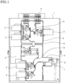
- FIG. 1 is a side sectional view of a gas-insulated switchgear
- FIG. 2 is an enlarged sectional view of a conductor contact portion.
- the gas-insulated switchgear 1 includes a circuit breaker 2, disconnectors and ground switches 3, busbars 4, power cables 6, and the like which are provided in sealed containers 5. In the sealed containers 5, insulation gas is sealed. A connection part between a conductor 7a in the sealed container 5 and a conductor 7b of the power cable 6 is referred to as a conductor contact portion 7.
- the conductor contact portion 7 is a part where it is difficult to perform bolt-fastening.
- a connection portion 12 between the circuit breaker 2 and a conductor, or a connection portion 13 between the ground switch 3 and a conductor, is formed by bolt-connection, in FIG. 1 .
- the connection portions may have a conductor contact structure in which the same member as the conductor contact portion 7 is interposed. In this case, one conductor is connected to the conductor 7a, and another conductor is connected to the conductor 7b.
- conductor contact structures are generally used also for parts where the switches are opened/closed.
- the conductor contact portion 7 has a contactor 7c mounted around the conductor 7a and the conductor 7b and contacting with the conductor 7a and the conductor 7b so as to clamp them.
- a contactor 7c mounted around the conductor 7a and the conductor 7b and contacting with the conductor 7a and the conductor 7b so as to clamp them.
- three ring-shaped coil springs 7d for applying a necessary load to the contactor 7c are provided to fix the conductor 7a and the conductor 7b.
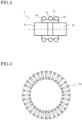
- the ring-shaped coil spring 7d is made of a general metal material for spring, such as a piano wire, a hard steel wire, or a stainless steel wire, and is obtained by forming a coil spring into a ring shape as shown in FIG. 3 .
- the conductor 7a, the conductor 7b, and the contactor 7c are made of a highly conductive material such as copper or aluminum. In FIG. 2 , the conductor 7a and the conductor 7b contact with the contactor 7c, and the contactor 7c is imparted with a load inward in the radial direction of the ring-shaped coil spring 7d.
- contact loads are produced between the contactor 7c and the conductor 7a and between the contactor 7c and the conductor 7b.
- current can be conducted through a path between the conductor 7a and the contactor 7c and a path between the contactor 7c and the conductor 7b.
- a greater electromagnetic repulsive force is produced at a contact part, and therefore a higher contact load is needed for overcoming the electromagnetic repulsive force.
- a ring-shaped spring 8a is mounted to the ring-shaped coil spring 7d.
- the ring-shaped spring 8a is made of a metal material for spring, such as a piano wire, a hard steel wire, or a stainless steel wire. As shown in FIG. 4 , the metal material for spring is formed into a ring shape so as to partially overlap each other.
- the ring diameter of the ring-shaped spring 8a is matched to the diameter on the inner circumferential side of the ring-shaped coil spring in advance.
- FIG. 5 is a sectional view of the ring-shaped coil spring 7d to which the ring-shaped spring 8a is mounted.
- the ring-shaped spring 8a On the inner side of the ring-shaped coil spring 7d, the ring-shaped spring 8a is mounted in a state of being matched to the inner diameter of the ring-shaped coil spring 7d and along the inner circumferential side in the coil of the ring-shaped coil spring 7d.
- an end of the ring-shaped spring 8a is passed through a spring gap of the ring-shaped coil spring 7d, whereby the ring-shaped spring 8a is mounted inside the ring-shaped coil spring 7d.
- a load for compressing the contactor 7c inward in the radial direction by the ring-shaped spring 8a is added to a load for compressing the contactor 7c inward in the radial direction by the ring-shaped coil spring 7d, thus providing an effect of increasing the contact load to the contactor 7c which is needed for current conduction in the conductor contact portion 7.
- the inserted ring-shaped spring 8a also has an effect of preventing the ring-shaped coil spring 7d from coming off even when a joined part of the ring-shaped coil spring 7d by welding or swaging is disconnected due to a manufacturing fault of the joined part.
- the number of mounted ring-shaped springs 8a is not limited to one and may be two or more.
- the load for compression inward in the radial direction by the ring-shaped spring 8a can be adjusted by changing the number of the ring-shaped springs 8a.
- the compression load inward in the radial direction may be changed by changing the materials of the ring-shaped springs 8a or changing the ring diameters thereof.
- the ring-shaped spring 8a wound by two or more turns may be used.
- the load for compression inward in the radial direction by the ring-shaped spring 8a can be adjusted by changing the number of turns.
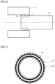
- FIG. 6 is a sectional view of a conductor contact portion of a contact (hereinafter, coil spring contact) using a ring-shaped coil spring according to embodiment 2.
- the ring-shaped coil spring 7d shown in FIG. 2 is made of a general metal material for spring, such as a piano wire, a hard steel wire, or a stainless steel wire, and therefore is low in current conduction performance.
- current is conducted via the contactor 7c.
- the contact pressure is imparted by the ring-shaped coil spring 7d.
- respective functions are separated.
- Coil spring contacts 9 shown in FIG. 6 are made of a highly conductive metal material for spring, such as a copper alloy, and the coil spring contacts 9 have both functions of conducting current and imparting a contact pressure. As shown in FIG. 6 , the cylindrical conductor 10 to which the coil spring contacts 9 are mounted is inserted into a recessed conductor 11, whereby current can be conducted through a path between the cylindrical conductor 10 and the coil spring contacts 9 and a path between the coil spring contacts 9 and the recessed conductor 11.
- FIG. 7 is a sectional view of the coil spring contact to which the ring-shaped spring is mounted according to embodiment 2.
- the ring-shaped spring 8a matched to the inner diameter of the ring-shaped coil spring 7d is added, to add a spring load inward in the radial direction.
- the coil spring contact 9 applies contact loads to both of the inner side and the outer side. That is, as shown in FIG. 7 , the ring-shaped spring 8a matched to the inner diameter of the coil spring contact 9 and along the inner circumferential side in the coil of the coil spring contact 9, and a ring-shaped spring 8b matched to the outer diameter of the coil spring contact 9 and along the outer circumferential side in the coil of the coil spring contact 9, are mounted to the coil spring contact 9, whereby it becomes possible to increase the contact loads to the radially inner side and the radially outer side of the coil spring contact 9.
- the ring-shaped spring 8b is made of a metal material for spring, such as a piano wire, a hard steel wire, or a stainless steel wire, as with the ring-shaped spring 8a. As shown in FIG. 4 , the metal material for spring is formed into a ring shape so as to partially overlap each other. The ring diameter of the ring-shaped spring 8b is matched to the diameter on the outer circumferential side of the ring-shaped coil spring in advance.
- an end of the ring-shaped spring 8b is passed through a spring gap of the coil spring contact 9, whereby the ring-shaped spring 8b is mounted inside the coil spring contact 9.
- the number of mounted ring-shaped springs 8b is not limited to one and may be two or more, as with the ring-shaped spring 8a.
- the load for compression outward in the radial direction by the ring-shaped spring 8b can be adjusted by changing the number of the ring-shaped springs 8b.
- the compression load outward in the radial direction may be changed by changing the materials of the ring-shaped springs 8b or changing the ring diameters thereof.
- the ring-shaped spring 8b wound by two or more turns may be used.
- the load for compression inward in the radial direction by the ring-shaped spring 8b can be adjusted by changing the number of turns.
- the ring-shaped springs 8a, 8b also have an effect of preventing the coil spring contact 9 from coming off even when a joined part of the coil spring contact 9 by welding or swaging is disconnected due to a manufacturing fault of the joined part.
Landscapes
- Engineering & Computer Science (AREA)
- General Engineering & Computer Science (AREA)
- Mechanical Engineering (AREA)
- Contacts (AREA)
- Springs (AREA)
- Gas-Insulated Switchgears (AREA)
Abstract
Description
- The present disclosure relates to a ring-shaped coil spring of switchgear, and a switchgear using the same.
- A switchgear is composed of a main circuit portion in which high voltage is applied, an operation mechanism portion for driving a switch of a main circuit, and a control circuit portion. In the main circuit portion, there is a part (1) where the switch is opened/closed, a part (2) where a function is not obtained if a connection part between the switch and another device is fixed by bolt-fastening, or a part (3) where it is difficult to perform bolt-fastening in view of assemblability. For these parts, conductor connection is made using a contactor instead of bolt-fastening.
- The contactor is provided with a garter spring imparted with a contact-pressure load needed for ensuring a function of not only allowing conduction of ordinary conduction current in the switchgear but also allowing conduction of short-time large current (see, for example, Patent Document 1).
- Patent Document 1:
Japanese Patent No. 5188176 - However, in order to adapt to a lineup of various contactors of switchgears, garter springs having different spring loads are needed, so that component types increase. On the other hand, if a garter spring corresponding to the maximum conduction current is set as standard specifications, such a garter spring has an excessive quality for a product for small conduction current.
- The present disclosure has been made to solve the above problem, and an object of the present invention is to provide a ring-shaped coil spring of switchgear that can obtain a necessary contact load without increasing types of ring-shaped coil springs.
- A ring-shaped coil spring of switchgear according to the present disclosure is mounted around a conductor and includes, in a coil, a ring-shaped spring for increasing a contact load to the conductor.
- The ring-shaped coil spring of switchgear according to the present disclosure can obtain a necessary contact load without increasing types of ring-shaped coil springs.
-
- [
FIG. 1] FIG. 1 is a side sectional view of a gas-insulated switchgear according toembodiment 1. - [
FIG. 2] FIG. 2 is an enlarged sectional view of a conductor contact portion according toembodiment 1. - [
FIG. 3] FIG. 3 is a sectional view of a ring-shaped coil spring. - [
FIG. 4] FIG. 4 is a perspective view of a ring-shaped spring according toembodiments - [
FIG. 5] FIG. 5 is a sectional view of the ring-shaped coil spring to which the ring-shaped spring is mounted according toembodiment 1. - [
FIG. 6] FIG. 6 is a sectional view of a conductor contact portion using a coil spring contact according toembodiment 2. - [
FIG. 7] FIG. 7 is a sectional view of the coil spring contact to which the ring-shaped springs are mounted according toembodiment 2. - Hereinafter, preferred embodiments of a ring-shaped coil spring of switchgear according to the present disclosure will be described with reference to the drawings. The ring-shaped coil spring of switchgear according to the present disclosure is applicable to a variety of switchgears. In the present embodiment, application to a gas-insulated switchgear will be described as an example. The same features and corresponding parts are denoted by the same reference characters, and the detailed description thereof is omitted. Also in other embodiments, components denoted by the same reference characters will not be described repeatedly.
-
FIG. 1 is a side sectional view of a gas-insulated switchgear, andFIG. 2 is an enlarged sectional view of a conductor contact portion. The gas-insulatedswitchgear 1 includes acircuit breaker 2, disconnectors andground switches 3,busbars 4,power cables 6, and the like which are provided in sealedcontainers 5. In the sealedcontainers 5, insulation gas is sealed. A connection part between aconductor 7a in the sealedcontainer 5 and aconductor 7b of thepower cable 6 is referred to as aconductor contact portion 7. - The
conductor contact portion 7 is a part where it is difficult to perform bolt-fastening. Aconnection portion 12 between thecircuit breaker 2 and a conductor, or aconnection portion 13 between theground switch 3 and a conductor, is formed by bolt-connection, inFIG. 1 . However, the connection portions may have a conductor contact structure in which the same member as theconductor contact portion 7 is interposed. In this case, one conductor is connected to theconductor 7a, and another conductor is connected to theconductor 7b. In addition, conductor contact structures are generally used also for parts where the switches are opened/closed. - In
FIG. 2 , theconductor contact portion 7 has acontactor 7c mounted around theconductor 7a and theconductor 7b and contacting with theconductor 7a and theconductor 7b so as to clamp them. Around thecontactor 7c, three ring-shaped coil springs 7d for applying a necessary load to thecontactor 7c are provided to fix theconductor 7a and theconductor 7b. - The ring-
shaped coil spring 7d is made of a general metal material for spring, such as a piano wire, a hard steel wire, or a stainless steel wire, and is obtained by forming a coil spring into a ring shape as shown inFIG. 3 . Theconductor 7a, theconductor 7b, and thecontactor 7c are made of a highly conductive material such as copper or aluminum. InFIG. 2 , theconductor 7a and theconductor 7b contact with thecontactor 7c, and thecontactor 7c is imparted with a load inward in the radial direction of the ring-shaped coil spring 7d. - Accordingly, contact loads are produced between the
contactor 7c and theconductor 7a and between thecontactor 7c and theconductor 7b. Thus, current can be conducted through a path between theconductor 7a and thecontactor 7c and a path between thecontactor 7c and theconductor 7b. As larger current is conducted, a greater electromagnetic repulsive force is produced at a contact part, and therefore a higher contact load is needed for overcoming the electromagnetic repulsive force. - In order to impart the above high contact load, a ring-
shaped spring 8a is mounted to the ring-shaped coil spring 7d. The ring-shaped spring 8a is made of a metal material for spring, such as a piano wire, a hard steel wire, or a stainless steel wire. As shown inFIG. 4 , the metal material for spring is formed into a ring shape so as to partially overlap each other. The ring diameter of the ring-shaped spring 8a is matched to the diameter on the inner circumferential side of the ring-shaped coil spring in advance. -
FIG. 5 is a sectional view of the ring-shaped coil spring 7d to which the ring-shaped spring 8a is mounted. On the inner side of the ring-shaped coil spring 7d, the ring-shaped spring 8a is mounted in a state of being matched to the inner diameter of the ring-shaped coil spring 7d and along the inner circumferential side in the coil of the ring-shaped coil spring 7d. In assembling, an end of the ring-shaped spring 8a is passed through a spring gap of the ring-shaped coil spring 7d, whereby the ring-shaped spring 8a is mounted inside the ring-shaped coil spring 7d. - In a case where the ring-
shaped coil spring 7d to which the ring-shaped spring 8a is mounted is used for theconductor contact portion 7 as shown inFIG. 2 , a load for compressing thecontactor 7c inward in the radial direction by the ring-shaped spring 8a is added to a load for compressing thecontactor 7c inward in the radial direction by the ring-shaped coil spring 7d, thus providing an effect of increasing the contact load to thecontactor 7c which is needed for current conduction in theconductor contact portion 7. Therefore, in a case where there is a lineup of various conduction currents, it is possible to adapt to such various conduction currents by mounting the ring-shaped spring 8a in the ring-shaped coil spring only in a case of large current while using the ring-shaped coil spring as standard specifications. That is, only one type of ring-shaped coil spring is needed, so that increase in the types of components can be suppressed and the cost is reduced. - With the configuration described above, it is possible to standardize the ring-
shaped coil spring 7d without increasing the types thereof, and increase the contact load by using the ring-shaped coil spring 7d provided with the ring-shaped spring 8a only in a case where conduction current is large. - In addition, the inserted ring-
shaped spring 8a also has an effect of preventing the ring-shaped coil spring 7d from coming off even when a joined part of the ring-shaped coil spring 7d by welding or swaging is disconnected due to a manufacturing fault of the joined part. - Further, regarding the ring-
shaped spring 8a inserted in the ring-shaped coil spring 7d, the number of mounted ring-shaped springs 8a is not limited to one and may be two or more. Thus, the load for compression inward in the radial direction by the ring-shaped spring 8a can be adjusted by changing the number of the ring-shaped springs 8a. In a case of mounting two or more ring-shaped springs 8a, the compression load inward in the radial direction may be changed by changing the materials of the ring-shaped springs 8a or changing the ring diameters thereof. - Further, the ring-
shaped spring 8a wound by two or more turns may be used. Thus, the load for compression inward in the radial direction by the ring-shapedspring 8a can be adjusted by changing the number of turns. -
FIG. 6 is a sectional view of a conductor contact portion of a contact (hereinafter, coil spring contact) using a ring-shaped coil spring according toembodiment 2. The ring-shapedcoil spring 7d shown inFIG. 2 is made of a general metal material for spring, such as a piano wire, a hard steel wire, or a stainless steel wire, and therefore is low in current conduction performance. Inembodiment 1 shown inFIG. 2 , current is conducted via thecontactor 7c. The contact pressure is imparted by the ring-shapedcoil spring 7d. Thus, respective functions are separated. -
Coil spring contacts 9 shown inFIG. 6 are made of a highly conductive metal material for spring, such as a copper alloy, and thecoil spring contacts 9 have both functions of conducting current and imparting a contact pressure. As shown inFIG. 6 , thecylindrical conductor 10 to which thecoil spring contacts 9 are mounted is inserted into a recessedconductor 11, whereby current can be conducted through a path between thecylindrical conductor 10 and thecoil spring contacts 9 and a path between thecoil spring contacts 9 and the recessedconductor 11. -
FIG. 7 is a sectional view of the coil spring contact to which the ring-shaped spring is mounted according toembodiment 2. Inembodiment 1, as shown inFIG. 5 , the ring-shapedspring 8a matched to the inner diameter of the ring-shapedcoil spring 7d is added, to add a spring load inward in the radial direction. - On the other hand, in a case of
FIG. 6 , thecoil spring contact 9 applies contact loads to both of the inner side and the outer side. That is, as shown inFIG. 7 , the ring-shapedspring 8a matched to the inner diameter of thecoil spring contact 9 and along the inner circumferential side in the coil of thecoil spring contact 9, and a ring-shapedspring 8b matched to the outer diameter of thecoil spring contact 9 and along the outer circumferential side in the coil of thecoil spring contact 9, are mounted to thecoil spring contact 9, whereby it becomes possible to increase the contact loads to the radially inner side and the radially outer side of thecoil spring contact 9. - The ring-shaped
spring 8b is made of a metal material for spring, such as a piano wire, a hard steel wire, or a stainless steel wire, as with the ring-shapedspring 8a. As shown inFIG. 4 , the metal material for spring is formed into a ring shape so as to partially overlap each other. The ring diameter of the ring-shapedspring 8b is matched to the diameter on the outer circumferential side of the ring-shaped coil spring in advance. - In assembling, an end of the ring-shaped
spring 8b is passed through a spring gap of thecoil spring contact 9, whereby the ring-shapedspring 8b is mounted inside thecoil spring contact 9. - Further, regarding the ring-shaped
spring 8b inserted in the ring-shapedcoil spring 7d, the number of mounted ring-shapedsprings 8b is not limited to one and may be two or more, as with the ring-shapedspring 8a. Thus, the load for compression outward in the radial direction by the ring-shapedspring 8b can be adjusted by changing the number of the ring-shapedsprings 8b. In a case of mounting two or more ring-shapedsprings 8b, the compression load outward in the radial direction may be changed by changing the materials of the ring-shapedsprings 8b or changing the ring diameters thereof. - Further, as with the ring-shaped
spring 8a, the ring-shapedspring 8b wound by two or more turns may be used. Thus, the load for compression inward in the radial direction by the ring-shapedspring 8b can be adjusted by changing the number of turns. - Thus, it becomes possible to standardize the type of the
coil spring contact 9 as described above, and add one or both of the ring-shapedsprings springs coil spring contact 9 from coming off even when a joined part of thecoil spring contact 9 by welding or swaging is disconnected due to a manufacturing fault of the joined part. - Although the disclosure is described above in terms of various exemplary embodiments and implementations, it should be understood that the various features, aspects, and functionality described in one or more of the individual embodiments are not limited in their applicability to the particular embodiment with which they are described, but instead can be applied, alone or in various combinations to one or more of the embodiments of the disclosure.
- It is therefore understood that numerous modifications which have not been exemplified can be devised without departing from the scope of the present disclosure. For example, at least one of the constituent components may be modified, added, or eliminated. At least one of the constituent components mentioned in at least one of the preferred embodiments may be selected and combined with the constituent components mentioned in another preferred embodiment.
-
- 1
- gas-insulated switchgear
- 2
- circuit breaker
- 3
- ground switch
- 4
- busbar
- 5
- sealed container
- 6
- power cable
- 7
- conductor contact portion
- 7a
- conductor
- 7b
- conductor
- 7c
- contactor
- 7d
- ring-shaped coil spring
- 8a,
- 8b ring-shaped spring
- 9
- coil spring contact
- 10
- cylindrical conductor
- 11
- recessed conductor
Claims (6)
- A ring-shaped coil spring of switchgear, the ring-shaped coil spring being mounted around a conductor, the ring-shaped coil spring comprising, in a coil, a ring-shaped spring for increasing a contact load to the conductor.
- The ring-shaped coil spring of switchgear according to claim 1, wherein
the conductor is a contactor that clamps and fixes two conductors. - The ring-shaped coil spring of switchgear according to claim 1 or 2, wherein
the ring-shaped spring is mounted along an inner circumferential side in the coil. - A ring-shaped coil spring of switchgear, the ring-shaped coil spring being mounted around a second conductor formed so as to be inserted and connected to a first conductor, wherein
a ring-shaped spring is mounted along an outer circumferential side in a coil so as to increase a contact load to the first conductor. - The ring-shaped coil spring of switchgear according to claim 4, wherein
another ring-shaped spring than the ring-shaped spring is mounted along an inner circumferential side in the coil, so as to increase a contact load to the second conductor. - A switchgear comprising the ring-shaped coil spring of switchgear according to any one of claims 1 to 5.
Applications Claiming Priority (1)
| Application Number | Priority Date | Filing Date | Title |
|---|---|---|---|
| PCT/JP2021/035833 WO2023053261A1 (en) | 2021-09-29 | 2021-09-29 | Ring-shaped coil spring of switchgear and switchgear using same |
Publications (2)
| Publication Number | Publication Date |
|---|---|
| EP4411773A1 true EP4411773A1 (en) | 2024-08-07 |
| EP4411773A4 EP4411773A4 (en) | 2024-11-13 |
Family
ID=81255842
Family Applications (1)
| Application Number | Title | Priority Date | Filing Date |
|---|---|---|---|
| EP21959308.4A Pending EP4411773A4 (en) | 2021-09-29 | 2021-09-29 | RING-SHAPED COIL SPRING FOR SWITCHGEAR AND SWITCHGEAR WITH IT |
Country Status (6)
| Country | Link |
|---|---|
| US (1) | US20240356247A1 (en) |
| EP (1) | EP4411773A4 (en) |
| JP (1) | JP7046295B1 (en) |
| CN (1) | CN117957733A (en) |
| TW (1) | TWI862981B (en) |
| WO (1) | WO2023053261A1 (en) |
Family Cites Families (8)
| Publication number | Priority date | Publication date | Assignee | Title |
|---|---|---|---|---|
| US3421734A (en) * | 1965-12-22 | 1969-01-14 | Trw Inc | Valve rotating device |
| JPH07151619A (en) * | 1993-11-30 | 1995-06-16 | Fuji Electric Co Ltd | Contact pressure measuring device for power equipment plug-in connection |
| JP3264353B2 (en) * | 1995-01-31 | 2002-03-11 | 三菱電機株式会社 | Tulip contact device |
| JP5188176B2 (en) | 2007-12-28 | 2013-04-24 | 三菱電機株式会社 | Ground switch |
| JP4212645B1 (en) * | 2008-04-14 | 2009-01-21 | 三菱電機株式会社 | Contact |
| CN102318154A (en) * | 2009-02-13 | 2012-01-11 | 三菱电机株式会社 | Contact device |
| CN102290264A (en) * | 2011-08-09 | 2011-12-21 | 正泰电气股份有限公司 | Conductive contact spring touch finger type connecting device |
| WO2014152744A1 (en) * | 2013-03-14 | 2014-09-25 | Bal Seal Engineering, Inc. | Canted coil spring with longitudinal component within and related methods |
-
2021
- 2021-09-29 US US18/683,617 patent/US20240356247A1/en active Pending
- 2021-09-29 JP JP2022503837A patent/JP7046295B1/en active Active
- 2021-09-29 EP EP21959308.4A patent/EP4411773A4/en active Pending
- 2021-09-29 WO PCT/JP2021/035833 patent/WO2023053261A1/en not_active Ceased
- 2021-09-29 CN CN202180102424.7A patent/CN117957733A/en active Pending
-
2022
- 2022-09-14 TW TW111134705A patent/TWI862981B/en active
Also Published As
| Publication number | Publication date |
|---|---|
| CN117957733A (en) | 2024-04-30 |
| TWI862981B (en) | 2024-11-21 |
| WO2023053261A1 (en) | 2023-04-06 |
| JPWO2023053261A1 (en) | 2023-04-06 |
| TW202314757A (en) | 2023-04-01 |
| US20240356247A1 (en) | 2024-10-24 |
| EP4411773A4 (en) | 2024-11-13 |
| JP7046295B1 (en) | 2022-04-01 |
Similar Documents
| Publication | Publication Date | Title |
|---|---|---|
| US9263199B2 (en) | Electrical contact arrangement and air insulated medium voltage circuit breaker including the electrical contact arrangement | |
| EP2077569B1 (en) | Vacuum switchgear | |
| JP5452555B2 (en) | Switchgear and switchgear operating method | |
| US20070246444A1 (en) | Contact system for an electrical switching device | |
| JPS58165221A (en) | Disconnecting switch | |
| US10141126B2 (en) | Vibration-limiting device for an apparatus comprising a switchgear and a switching device, such as a circuit breaker, and apparatus comprising said vibration-limiting device | |
| JP2000268685A (en) | Switchgear | |
| EP4411773A1 (en) | Ring-shaped coil spring of switchgear and switchgear using same | |
| CN102034640A (en) | Circuit breaker with parallel rated current paths | |
| JP2008524974A (en) | High voltage switchgear assembly | |
| HK40105903A (en) | Ring-shaped coil spring of switchgear and switchgear using same | |
| JP4232766B2 (en) | Vacuum switchgear | |
| JP3206729B2 (en) | Current limiting device | |
| US12412713B2 (en) | Contact assembly | |
| JP2009129855A (en) | Vacuum circuit breaker | |
| JP4004681B2 (en) | Switchgear | |
| KR20240142356A (en) | Gas insulated switchgear | |
| CN111971772B (en) | Flexible conductor for isolating switch and isolating switch | |
| JP4288648B2 (en) | Vacuum switchgear | |
| EP4277058A1 (en) | Switchgear and gas-insulated switchgear | |
| KR200475885Y1 (en) | gas insulated switchgear | |
| KR20230148480A (en) | Vacuum interrupter for arc eliminators | |
| JP2016163499A (en) | Switchgear | |
| EP3477310B1 (en) | Voltage detection device and gas insulation switchgear apparatus having voltage detection device mounted thereon | |
| CN111480209A (en) | winding assembly |
Legal Events
| Date | Code | Title | Description |
|---|---|---|---|
| STAA | Information on the status of an ep patent application or granted ep patent |
Free format text: STATUS: THE INTERNATIONAL PUBLICATION HAS BEEN MADE |
|
| PUAI | Public reference made under article 153(3) epc to a published international application that has entered the european phase |
Free format text: ORIGINAL CODE: 0009012 |
|
| STAA | Information on the status of an ep patent application or granted ep patent |
Free format text: STATUS: REQUEST FOR EXAMINATION WAS MADE |
|
| 17P | Request for examination filed |
Effective date: 20240228 |
|
| AK | Designated contracting states |
Kind code of ref document: A1 Designated state(s): AL AT BE BG CH CY CZ DE DK EE ES FI FR GB GR HR HU IE IS IT LI LT LU LV MC MK MT NL NO PL PT RO RS SE SI SK SM TR |
|
| REG | Reference to a national code |
Ref country code: DE Ref legal event code: R079 Free format text: PREVIOUS MAIN CLASS: H01H0033650000 Ipc: H01H0001380000 |
|
| A4 | Supplementary search report drawn up and despatched |
Effective date: 20241010 |
|
| RIC1 | Information provided on ipc code assigned before grant |
Ipc: H02B 13/035 20060101ALN20241004BHEP Ipc: H01R 13/17 20060101ALI20241004BHEP Ipc: H01R 4/48 20060101ALI20241004BHEP Ipc: F16F 1/04 20060101ALI20241004BHEP Ipc: H01H 1/38 20060101AFI20241004BHEP |
|
| DAV | Request for validation of the european patent (deleted) | ||
| DAX | Request for extension of the european patent (deleted) |