EP4411770A1 - Monitoring system for a mechanically driven circuit breaker - Google Patents
Monitoring system for a mechanically driven circuit breaker Download PDFInfo
- Publication number
- EP4411770A1 EP4411770A1 EP23154779.5A EP23154779A EP4411770A1 EP 4411770 A1 EP4411770 A1 EP 4411770A1 EP 23154779 A EP23154779 A EP 23154779A EP 4411770 A1 EP4411770 A1 EP 4411770A1
- Authority
- EP
- European Patent Office
- Prior art keywords
- circuit breaker
- state
- sensor data
- actuator
- main actuator
- Prior art date
- Legal status (The legal status is an assumption and is not a legal conclusion. Google has not performed a legal analysis and makes no representation as to the accuracy of the status listed.)
- Granted
Links
Images








Classifications
-
- H—ELECTRICITY
- H01—ELECTRIC ELEMENTS
- H01H—ELECTRIC SWITCHES; RELAYS; SELECTORS; EMERGENCY PROTECTIVE DEVICES
- H01H33/00—High-tension or heavy-current switches with arc-extinguishing or arc-preventing means
- H01H33/02—Details
- H01H33/28—Power arrangements internal to the switch for operating the driving mechanism
- H01H33/38—Power arrangements internal to the switch for operating the driving mechanism using electromagnet
-
- G—PHYSICS
- G01—MEASURING; TESTING
- G01R—MEASURING ELECTRIC VARIABLES; MEASURING MAGNETIC VARIABLES
- G01R31/00—Arrangements for testing electric properties; Arrangements for locating electric faults; Arrangements for electrical testing characterised by what is being tested not provided for elsewhere
- G01R31/327—Testing of circuit interrupters, switches or circuit-breakers
-
- G—PHYSICS
- G01—MEASURING; TESTING
- G01R—MEASURING ELECTRIC VARIABLES; MEASURING MAGNETIC VARIABLES
- G01R1/00—Details of instruments or arrangements of the types included in groups G01R5/00 - G01R13/00 and G01R31/00
- G01R1/02—General constructional details
- G01R1/04—Housings; Supporting members; Arrangements of terminals
- G01R1/0408—Test fixtures or contact fields; Connectors or connecting adaptors; Test clips; Test sockets
- G01R1/0416—Connectors, terminals
-
- H—ELECTRICITY
- H01—ELECTRIC ELEMENTS
- H01H—ELECTRIC SWITCHES; RELAYS; SELECTORS; EMERGENCY PROTECTIVE DEVICES
- H01H71/00—Details of the protective switches or relays covered by groups H01H73/00 - H01H83/00
- H01H71/04—Means for indicating condition of the switching device
- H01H2071/044—Monitoring, detection or measuring systems to establish the end of life of the switching device, can also contain other on-line monitoring systems, e.g. for detecting mechanical failures
-
- H—ELECTRICITY
- H01—ELECTRIC ELEMENTS
- H01H—ELECTRIC SWITCHES; RELAYS; SELECTORS; EMERGENCY PROTECTIVE DEVICES
- H01H3/00—Mechanisms for operating contacts
- H01H3/22—Power arrangements internal to the switch for operating the driving mechanism
- H01H3/28—Power arrangements internal to the switch for operating the driving mechanism using electromagnet
Definitions
- the present invention relates to monitoring system for a mechanically driven circuit breaker, and monitoring methods for a mechanically driven circuit breaker.
- Mechanically driven circuit breakers are systems that can have a very long lifetime, but which might only be seldomly used.
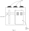
- Fig. 1 shows an example of a mechanically driven circuit breaker system, with Fig. 2 showing a schematic representation of the circuit breaker of Fig. 1 .
- a main actuator 10 engages with a main shaft of the circuit breaker system to activate the poles to close and indeed also to open.
- a closing shaft 60 is activated to enable the main actuator to engage with the main shaft to transition to circuit breaker poles (or pole) from an open orientation to a closed orientation, where movable contacts (or contact) is brought into contact with fixed contacts (or contact).
- An opening shaft 60 is activated to enable the main actuator to engage with the main shaft to transition to circuit breaker poles (or pole) from a closed orientation to an open orientation, where movable contacts (or contact) is separated from the fixed contacts (or contact).
- One failure that can occur is the jamming of the opening shaft 60 and/or closing shaft 50 in the main actuator 10. This failure is critical to the system reliability and security as it prevents the entire device from operating.
- a monitoring system for a mechanically driven circuit breaker comprising a fixed contact and a movable contact and a main actuator. In a first state of the circuit breaker the moveable contact is spaced from the fixed contact and in a second state of the circuit breaker the moveable contact is in contact with the fixed contact.
- the main actuator is configured to transition the circuit breaker from the first state to the second state.
- the monitoring system comprises:
- the sensor data comprises rotational or linear movement data of the part of the main actuator.
- the sensor data comprises force and/or torque data applied to the part of the main actuation.
- the sensor data comprises force and/or torque data exerted by the actuation device.
- the sensor data comprises rotational or linear movement data of at least one part of the actuation device.
- the at least one part of the actuation device comprises a rotor of a rotational actuator or a plunger of a translational actuator.
- the determination if the circuit breaker has a fault comprises utilization of reference sensor data.
- a monitoring system for a mechanically driven circuit breaker comprising a fixed contact and a movable contact and a main actuator. In a first state of the circuit breaker the moveable contact is spaced from the fixed contact and in a second state of the circuit breaker the moveable contact is in contact with the fixed contact.
- the main actuator is configured to transition the circuit breaker from the second state to the first state.
- the monitoring system comprises:
- the sensor data comprises rotational or linear movement data of the part of the main actuator.
- the sensor data comprises force and/or torque data applied to the part of the main actuation.
- the sensor data comprises force and/or torque data exerted by the actuation device.
- the sensor data comprises rotational or linear movement data of at least one part of the actuation device.
- the at least one part of the actuation device comprises a rotor of a rotational actuator or a plunger of a translational actuator.
- a monitoring method for a mechanically driven circuit breaker comprises a fixed contact and a movable contact and a main actuator. In a first state of the circuit breaker the moveable contact is spaced from the fixed contact and in a second state of the circuit breaker the moveable contact is in contact with the fixed contact.
- the main actuator is configured to transition the circuit breaker from the first state to the second state.
- the monitoring method comprises:
- a monitoring method for a mechanically driven circuit breaker comprises a fixed contact and a movable contact and a main actuator. In a first state of the circuit breaker the moveable contact is spaced from the fixed contact and in a second state of the circuit breaker the moveable contact is in contact with the fixed contact.
- the main actuator is configured to transition the circuit breaker from the second state to the first state.
- the monitoring method comprises:
- Figs. 3-16 relate to the new monitoring system for a mechanically driven circuit breaker and monitoring methods for a mechanically driven circuit breaker.
- the circuit breaker comprises a fixed contact and a movable contact and a main actuator 10.
- the moveable contact In a first state of the circuit breaker the moveable contact is spaced from the fixed contact and in a second state of the circuit breaker the moveable contact is in contact with the fixed contact.
- the main actuator (10) is configured to transition the circuit breaker from the first state to the second state.
- the monitoring system comprises:
- the part 50 of the main actuator 10 is a closing shaft 50.
- the part 50 of the main actuator 10 is a closing hook 50.
- the sensor data comprises rotational or linear movement data of the part 50 of the main actuator 10.
- the sensor data comprises force and/or torque data applied to the part 50 of the main actuation 10.
- the sensor data comprises force and/or torque data exerted by the actuation device 20.
- the force and/or torque data exerted by the actuator device is measured with respect to at least one part 70, 80 of the actuation device 20.
- the sensor data comprises rotational or linear movement data of at least one part 70, 80 of the actuation device 20.
- the at least one part of the actuation device 20 comprises a rotor 70 of a rotational actuator or a plunger 80 of a translational actuator.
- the actuation device 20 that is used to apply a micromotion to a part 50 of the main actuator 10 can itself be a sensor in terms of force/torque information applied by it to the part 50 can be derived by appropriate measurements by a sensor/measurement system.
- separate sensors to the actuation device
- the determination if the circuit breaker has a fault comprises utilization of reference sensor data.
- a reference circuit breaker comprises a fixed contact and a movable contact and a main actuator.
- the moveable contact In a first state of the reference circuit breaker the moveable contact is spaced from the fixed contact and in a second state of the reference circuit breaker the moveable contact is in contact with the fixed contact.
- a main actuator of the reference circuit is configured to transition the reference circuit breaker from the first state to the second state.
- a reference actuation device is configured to apply a micromotion to a part of the main actuator involved in transitioning the reference circuit breaker from the first state to the second state without the reference circuit breaker transitioning from the first state to second state.
- At least one sensor is configured to acquire the reference sensor data associated with the application of the micromotion to the part of the main actuator.
- an equivalent circuit breaker system and monitoring system to that being used in the field for actual monitoring, can be utilized in a whole series of situations where micromotion is applied to the part of the main actuator, where the main actuator is operating correctly and indeed operating with different failures, in order that reference sensor data can be acquired for healthy operation and for unhealthy operation.
- reference sensor data can be acquired for healthy operation and for unhealthy operation.
- a simple comparison could be made, however a neural network could be trained on the reference sensor data, which then when provided with real in the field data can determine not only if there is a fault with the main actuator, but determine what the fault is.
- the reference sensor data comprises rotational or linear movement data of the part of the main actuator of the reference circuit breaker.
- the reference sensor data comprises force and/or torque data applied to the part of the main actuation of the reference circuit breaker.
- the reference sensor data comprises force and/or torque data exerted by the reference actuation device.
- the force and/or torque data exerted by the reference actuator device is measured with respect to at least one part of the actuation device.
- the sensor data comprises rotational or linear movement data of at least one part of the reference actuation device.
- the at least one part of the actuation device comprises a rotor of a rotational actuator or a plunger of a translational actuator.
- the circuit breaker comprising a fixed contact and a movable contact and a main actuator 10.
- the moveable contact In a first state of the circuit breaker the moveable contact is spaced from the fixed contact and in a second state of the circuit breaker the moveable contact is in contact with the fixed contact.
- the main actuator 10 is configured to transition the circuit breaker from the second state to the first state.
- the monitoring system comprises:
- the part 60 of the main actuator 10 is an opening shaft 60.
- the part 60 of the main actuator 10 is an opening hook 60.
- the sensor data comprises rotational or linear movement data of the part 60 of the main actuator 10.
- the sensor data comprises force and/or torque data applied to the part 60 of the main actuation 20.
- the sensor data comprises force and/or torque data exerted by the actuation device 20.
- the force and/or torque data exerted by the actuator device is measured with respect to at least one part (60, 70) of the actuation device (20).
- the sensor data comprises rotational or linear movement data of at least one part (60, 70) of the actuation device (20).
- the at least one part of the actuation device (20) comprises a rotor 70 of a rotational actuator or a plunger (80) of a translational actuator.
- the actuation device 20 that is used to apply a micromotion to a part 60 of the main actuator 10 can itself be a sensor in terms of force/torque information applied by it to the part 60 can be derived by appropriate measurements by a sensor/measurement system.
- separate sensors to the actuation device
- the determination if the circuit breaker has a fault comprises utilization of reference sensor data.
- a reference circuit breaker comprises a fixed contact and a movable contact and a main actuator. I in a first state of the reference circuit breaker the moveable contact is spaced from the fixed contact and in a second state of the reference circuit breaker the moveable contact is in contact with the fixed contact.
- a main actuator of the reference circuit breaker is configured to transition the reference circuit breaker from the second state to the first state.
- a reference actuation device is configured to apply a micromotion to a part of the main actuator involved in transitioning the reference circuit breaker from the second state to the first state without the reference circuit breaker transitioning from the second state to first state.
- At least one sensor is configured to acquire the reference sensor data associated with the application of the micromotion to the part of the main actuator.
- an equivalent circuit breaker system and monitoring system to that being used in the field for actual monitoring, can be utilized in a whole series of situations where micromotion is applied to the part of the main actuator, where the main actuator is operating correctly and indeed operating with different failures, in order that reference sensor data can be acquired for healthy operation and for unhealthy operation.
- reference sensor data can be acquired for healthy operation and for unhealthy operation.
- a simple comparison could be made, however a neural network could be trained on the reference sensor data, which then when provided with real in the field data can determine not only if there is a fault with the main actuator, but determine what the fault is.
- the reference sensor data comprises rotational or linear movement data of the part of the main actuator of the reference circuit breaker.
- the reference sensor data comprises force and/or torque data applied to the part of the main actuation of the reference circuit breaker.
- the reference sensor data comprises force and/or torque data exerted by the reference actuation device.
- the force and/or torque data exerted by the reference actuator device is measured with respect to at least one part of the actuation device.
- the sensor data comprises rotational or linear movement data of at least one part of the reference actuation device.
- the at least one part of the actuation device comprises a rotor of a rotational actuator or a plunger of a translational actuator.
- the circuit breaker comprises a fixed contact and a movable contact and a main actuator 10. I in a first state of the circuit breaker the moveable contact is spaced from the fixed contact and in a second state of the circuit breaker the moveable contact is in contact with the fixed contact.
- the main actuator 10 is configured to transition the circuit breaker from the first state to the second state.
- the monitoring method comprises:
- the part 50 of the main actuator 10 is a closing shaft 50.
- the part 50 of the main actuator 10 is a closing hook 50.
- the sensor data comprises rotational or linear movement data of the part 50 of the main actuator 10.
- the sensor data comprises force and/or torque data applied to the part 50 of the main actuation 20.
- the sensor data comprises force and/or torque data exerted by the actuation device 20.
- the force and/or torque data exerted by the actuator device is measured with respect to at least one part 70, 80 of the actuation device 20.
- the sensor data comprises rotational or linear movement data of at least one part 70, 80 of the actuation device 20.
- the at least one part of the actuation device 20 comprises a rotor 70 of a rotational actuator or a plunger 80 of a translational actuator.
- the determining if the circuit breaker has a fault comprises utilizing reference sensor data.
- a reference circuit breaker comprises a fixed contact and a movable contact and a main actuator.
- the moveable contact In a first state of the reference circuit breaker the moveable contact is spaced from the fixed contact and in a second state of the reference circuit breaker the moveable contact is in contact with the fixed contact.
- a main actuator of the reference circuit breaker is configured to transition the reference circuit breaker from the first state to the second state.
- a reference actuation device is configured to apply a micromotion to a part of the main actuator involved in transitioning the reference circuit breaker from the first state to the second state without the reference circuit breaker transitioning from the first state to second state.
- At least one sensor is configured to acquire the reference sensor data associated with the application of the micromotion to the part of the main actuator.
- the reference sensor data comprises rotational or linear movement data of the part of the main actuator of the reference circuit breaker.
- the reference sensor data comprises force and/or torque data applied to the part of the main actuation of the reference circuit breaker.
- the reference sensor data comprises force and/or torque data exerted by the reference actuation device.
- the force and/or torque data exerted by the reference actuator device is measured with respect to at least one part of the actuation device.
- the sensor data comprises rotational or linear movement data of at least one part of the reference actuation device.
- the at least one part of the actuation device comprises a rotor of a rotational actuator or a plunger of a translational actuator.
- the circuit breaker comprising a fixed contact and a movable contact and a main actuator 10.
- the moveable contact In a first state of the circuit breaker the moveable contact is spaced from the fixed contact and in a second state of the circuit breaker the moveable contact is in contact with the fixed contact.
- the main actuator 10 is configured to transition the circuit breaker from the second state to the first state.
- the monitoring method comprises:
- the part 60 of the main actuator 10 is an opening shaft 60.
- the part 60 of the main actuator 10 is an opening hook 60.
- the sensor data comprises rotational or linear movement data of the part 60 of the main actuator 10.
- the sensor data comprises force and/or torque data applied to the part 60 of the main actuation 20.
- the sensor data comprises force and/or torque data exerted by the actuation device 20.
- the force and/or torque data exerted by the actuator device is measured with respect to at least one part 60, 70 of the actuation device 20.
- the sensor data comprises rotational or linear movement data of at least one part 60, 70 of the actuation device 20.
- the at least one part of the actuation device 20 comprises a rotor 70 of a rotational actuator or a plunger 80 of a translational actuator.
- the determining if the circuit breaker has a fault comprises utilizing reference sensor data.
- a reference circuit breaker comprises a fixed contact and a movable contact and a main actuator.
- the moveable contact In a first state of the reference circuit breaker the moveable contact is spaced from the fixed contact and in a second state of the reference circuit breaker the moveable contact is in contact with the fixed contact.
- a main actuator of the reference circuit breaker is configured to transition the reference circuit breaker from the second state to the first state.
- a reference actuation device is configured to apply a micromotion to a part of the main actuator involved in transitioning the reference circuit breaker from the second state to the first state without the reference circuit breaker transitioning from the second state to first state.
- At least one sensor is configured to acquire the reference sensor data associated with the application of the micromotion to the part of the main actuator.
- the reference sensor data comprises rotational or linear movement data of the part of the main actuator of the reference circuit breaker.
- the reference sensor data comprises force and/or torque data applied to the part of the main actuation of the reference circuit breaker.
- the reference sensor data comprises force and/or torque data exerted by the reference actuation device.
- the force and/or torque data exerted by the reference actuator device is measured with respect to at least one part of the actuation device.
- the sensor data comprises rotational or linear movement data of at least one part of the reference actuation device.
- the at least one part of the actuation device comprises a rotor of a rotational actuator or a plunger of a translational actuator.
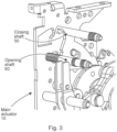
- Fig. 3 shows part of a main actuator 10 of a circuit breaker or circuit breaker system, that can operate one or more circuit breaker poles to close or open.
- the main actuator 10 has an opening shaft 50 and a closing shaft 60.
- the opening shaft 50 and closing shaft 60 are in effect latching elements.
- the opening shaft 50 when activated enables the main actuator 10 to operate a main shaft of the circuit breaker to transition the circuit breaker from a closed state to an open state.
- the closing shaft 60 when activated enables the main actuator 10 to operate a main shaft of the circuit breaker to transition the circuit breaker from the open state to the closed state.
- the opening shaft 50 and the closing shaft 60 are formed in such a way such that a micromotion, a small rotation of the shafts, can be made without the main actuator being activated to operate the main shaft to transition the circuit breaker from the open state to the closed state or from the closed state to the open state.
- a main actuator that enables such a micromotion to be made without actuation of the main actuator as such is described in EP3693985B1 , which for a closing operation describes that the main actuator comprises a closing shaft, and a closing hook.
- the closing shaft has a longitudinal axis.
- the closing shaft comprises an interaction region at an interaction location along the longitudinal axis.
- the closing shaft is configured to rotate about the longitudinal axis.
- the closing shaft In a first state the closing shaft is configured to be at a first rotational position, wherein the closing hook is configured to be in contact with the interaction region such that the closing hook cannot rotate in a first rotational direction.
- the closing shaft In a second state the closing shaft is configured to be at a second rotational position, wherein the closing hook is configured to rotate in the first rotational direction past the interaction region of the closing shaft.
- the main actuator is configured to transition from the first state to a third state, wherein the closing shaft is configured to rotate from the first rotational position to a third rotational position, wherein the closing hook is configured to be in contact with the interaction region such that the closing hook has been rotated in a second rotational direction opposite to the first rotational direction.
- a similar operation means applies for an opening operation, where the main actuator comprises an opening shaft and an opening hook.
- the opening shaft has a longitudinal axis.
- the opening shaft comprises an interaction region at an interaction location along the longitudinal axis.
- the opening shaft is configured to rotate about the longitudinal axis.
- the opening shaft In a first state the opening shaft is configured to be at a first rotational position, and the opening hook is configured to be in contact with the interaction region such that the opening hook cannot rotate in a first rotational direction.
- the opening shaft In a second state the opening shaft is configured to be at a second rotational position, and the opening hook is configured to rotate in the first rotational direction past the interaction region of the opening shaft.
- the main actuator is configured to transition from the first state to a third state. In the transition from the first state to the third state the opening shaft is configured to rotate from the first rotational position to a third rotational position, and the opening hook is configured to be in contact with the interaction region such that the opening hook has been rotated in a second rotational direction opposite to the first rotational direction.
- the present monitoring system for a mechanically driven circuit breaker and monitoring methods for a mechanically driven circuit breaker, is configured to operate with such a main actuator (and other main actuators) that enable a micromotion of parts of the main actuator, that are associated with full actuation of the main actuator, but where the micromotion does not actually lead to full actuation.
- the main actuator is performing correctly or has a defect such as corrosion or bearing grease degradation, where for example there may not be the correct magnitude of displacement, or a slower displacement that anticipated, or a greater force/torque, or indeed lesser force/torque required to be applied (or more than one of these and possible all), that can then be used to indicate that the main actuator has a fault and remedial action is required.
- the monitoring system for a mechanically driven circuit breaker and monitoring methods for a mechanically driven circuit breaker are described in further detail below.
- the new technique involves actively applying a small motion to the circuit breaker system, which moves the main actuator but does not switch the entire circuit breaker in order to assess whether the circuit breaker system is still healthy or not.
- the applied small (micro) motion is also be measured/quantified and it is evaluated if the measured motion with respect to displacement and or force and or torque, for example with respect to a certain force/torque derived from an actuator device that applies the micromotion to declare the system to be healthy or not.
- these breakers are driven by a main actuator (see figs. 1-2 ).
- a main actuator see figs. 1-2 .
- To initialize the switching there is usually one shaft each for opening and closing. These shafts release some mechanism (for example a mechanical hook) to start the motion.
- a further actuation device is used to move the corresponding (opening or closing) shaft. In state-of-the-art systems, there are devices can move these shafts by a certain defined actuation angle.
- the inventors realized that by applying a micromotion to an appropriate part involved in the switching of the circuit breaker, but without actually switching it, and measuring and assessing this micromotion, an active monitoring technique could be provided to monitor and prevent the system from degradation.
- the new technique can be considered to involve three parts to realize an active system health monitoring of mechanically driven circuit breakers: First, an electromagnetic actuation device 20 is used that can exert a controlled force/torque to the system to initialize a micro motion that does move the system, but where this motion is small enough to not switch the circuit breaker. Second, a sensor 30 or sensing element is used which measures the motion that takes place. Third, a processing unit 40 or logical unit is used to assess whether the measured motion corresponding to a certain applied force/torque is sufficient to classify the system as being healthy. Fig. 4 shows a schematic of these three elements.
- the actuation device can either replace current actuators adding the micromotion functionality within one device, that is also capable of initializing the normal switching, or be added to not actuate the opening/closing shaft under normal conditions, but solely for the micro motion.
- Electromagnetic actuators can be based on a variety of different working principles. Comparable to electric motors, it is possible to use induction, permanent magnets, the reluctance effect or similar effects and combinations of them.
- the reluctance effect has some special advantages for the application of a micro motion and will therefore be exemplified in more detail. Some advantages are:
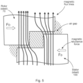
- Magnetic reluctance actuators are a special form of an electromagnetic actuator. Besides magnetic Lorentz Forces due to the interaction of a magnetic field and a current, Reluctance Forces (or -torque) come into play, when magnetic flux crosses an air gap in between ferromagnetic solids, which is changing in shape or width during the motion of the actuator. More illustrative, the reluctance force tends to minimize the resistance against the magnetic flux (that is the reluctance) to cross the air gap and thus minimize the magnetic energy. This is achieved, if the magnetic flux lines are as least distorted as possible when crossing the air gap. Fig.
- FIG. 5 shows a sketch of such a process, that shows forces F R due to magnetic reluctance, where the rotor 70 and stator 100 of the actuation device 20 are shown, along with magnetic flux lines, air gap and the magnetic reluctance force F R .
- reluctance motors certain stepper motors or reluctance assisted synchronous machines are predominant examples.
- the principle is used to design actuators both for rotary and translatory motions with limited stroke.
- Figs. 6-8 shows examples of actuation devices 20 suitable for utilization within the new monitoring system, where rotors 70, stators 100, plunger 80, coil 110, and spring 120 are shown with respect to different actuation devices, along with the air gap.
- rotary reluctance actuators can enable both the normal circuit breaker operation with a rotation angle ⁇ A and a micro motion with an angle ⁇ M ⁇ ⁇ A. Furthermore, they are able to measure both the position/angle of the moving part and the applied force/torque in the actuator.
- Such devices comprises several functional elements:
- reluctance actuator devices The main part of reluctance actuator devices is built from a stator and rotor/plunger made from (soft) ferromagnetic material.
- the geometrical design of these elements is such, that there are two to three magnetic poles, where electric coils are attached to create a magnetic field.
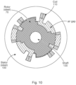
- Figs. 9-11 shows some exemplary cut sections through the axial direction of exemplar rotary actuator devices and Fig. 12 depicting an exemplary 3D view of the device in Fig. 11 with 2x3 symmetrical magnetic poles and corresponding coils.
- Reset Spring A mechanical reset spring can replace the reset pole ( Fig. 9 and Fig. 11 ) to passively bring the rotor back to its rest position or contribute to the torque created by a reset pole (as in Fig. 11 )).
- reset pole Fig. 9 and Fig. 11
- End Stops The end stops in the versions of Fig. 10 and Fig. 11 are optional but provide for defined actuation and rest positions of the system and may improve the hold torque of the actuator due to tangential magnetic flux components in the air gap.
- the sensing element is able to measure (or provide for an estimate of) both the applied force/torque and the current position/angle of the device. Both functionalities can either be integrated into the actuator or fulfilled by a dedicated sensor.
- the actuator force/torque can be estimated based on a flux-torque map.
- An additional force/torque sensor can either be integrated to the actuator device or be placed externally to the device.
- the actuator position/angle can be estimated based on the current wave form.
- the induced voltage can be measured in the energized phase, an unenergized phase or an additional sensing coil. Based on the induced voltage the actuator device position/angle can be estimated
- the impedance of an actuator coil or a dedicated sensing coil is a function of the actuator device position/angle. Thus, by measuring the impedance, the position/angle can be determined.
- a dedicated position/angle sensor can either be integrated to the actuator device or be placed externally of the device.
- the actuator device control provides power to the actuator phases. It is connected to some power source (e.g. providing a DC voltage V 0) and involves some switching elements, for example realized by transistors to control the current flowing through the actuator phases.
- some power source e.g. providing a DC voltage V 0
- switching elements for example realized by transistors to control the current flowing through the actuator phases.
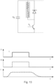
- Figs. 13 , 14 and 15 depict some possible topologies to activate and deactivate a certain phase.
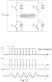
- Fig. 15 shows an example of an electronic unit for 3 phases using H-bridges including 2 transistors and 2 diodes for each phase.
- the processing unit logical unit evaluates the sensor data (force/torque and position/angle) using an appropriate algorithm to determine whether the system is considered healthy or not. This may involve a simple threshold for the position/angle value at a certain force/torque, or some more advanced algorithm such as a trained machine learning algorithm, using reference data for healthy and unhealthy main actuators.
Landscapes
- Physics & Mathematics (AREA)
- General Physics & Mathematics (AREA)
- Electromagnetism (AREA)
- Arc-Extinguishing Devices That Are Switches (AREA)
Abstract
- an actuation device (20);
- at least one sensor (30); and
- a processing unit (40);
wherein the actuation device (20) is configured to apply a micromotion to a part (50) of the main actuator (10) involved in transitioning the circuit breaker from the first state to the second state without the circuit breaker transitioning from the first state to second state;
wherein the at least one sensor (30) is configured to acquire sensor data associated with the application of the micromotion to the part (50) of the main actuator;
wherein the at least one sensor (30) is configured to provide the sensor data to the processing unit (40);
wherein the processing unit is configured to determine if the circuit breaker has a fault, wherein the determination if the circuit breaker has a fault comprises utilization of the sensor data.
Description
- The present invention relates to monitoring system for a mechanically driven circuit breaker, and monitoring methods for a mechanically driven circuit breaker.
- Mechanically driven circuit breakers are systems that can have a very long lifetime, but which might only be seldomly used.
- They can suffer from different failure cases, for example due to corrosion or bearing grease degradation.
-
Fig. 1 shows an example of a mechanically driven circuit breaker system, withFig. 2 showing a schematic representation of the circuit breaker ofFig. 1 . - As shown in
Figs. 1-2 , a three phase circuit breaker system is shown, where there are three poles. There can however only be one pole. Amain actuator 10 engages with a main shaft of the circuit breaker system to activate the poles to close and indeed also to open. Aclosing shaft 60 is activated to enable the main actuator to engage with the main shaft to transition to circuit breaker poles (or pole) from an open orientation to a closed orientation, where movable contacts (or contact) is brought into contact with fixed contacts (or contact). Anopening shaft 60 is activated to enable the main actuator to engage with the main shaft to transition to circuit breaker poles (or pole) from a closed orientation to an open orientation, where movable contacts (or contact) is separated from the fixed contacts (or contact). - One failure that can occur is the jamming of the
opening shaft 60 and/or closingshaft 50 in themain actuator 10. This failure is critical to the system reliability and security as it prevents the entire device from operating. - There is a need to address these issues.
- Therefore, it would be advantageous to have an improved technique to stop a main actuator of a circuit breaker from affecting the performance of the circuit breaker.
- The object of the present invention is solved with the subject matter of the independent claims, wherein further embodiments are incorporated in the dependent claims.
- In a first aspect, there is provided a monitoring system for a mechanically driven circuit breaker. The circuit breaker comprises a fixed contact and a movable contact and a main actuator. In a first state of the circuit breaker the moveable contact is spaced from the fixed contact and in a second state of the circuit breaker the moveable contact is in contact with the fixed contact. The main actuator is configured to transition the circuit breaker from the first state to the second state. The monitoring system comprises:
- an actuation device;
- at least one sensor; and
- a processing unit,
- In an example, the sensor data comprises rotational or linear movement data of the part of the main actuator.
- In an example, the sensor data comprises force and/or torque data applied to the part of the main actuation.
- In an example, the sensor data comprises force and/or torque data exerted by the actuation device.
- In an example, the sensor data comprises rotational or linear movement data of at least one part of the actuation device.
- In an example, the at least one part of the actuation device comprises a rotor of a rotational actuator or a plunger of a translational actuator.
- In an example, the determination if the circuit breaker has a fault comprises utilization of reference sensor data.
- In a second aspect, there is provided a monitoring system for a mechanically driven circuit breaker. The circuit breaker comprises a fixed contact and a movable contact and a main actuator. In a first state of the circuit breaker the moveable contact is spaced from the fixed contact and in a second state of the circuit breaker the moveable contact is in contact with the fixed contact. The main actuator is configured to transition the circuit breaker from the second state to the first state. The monitoring system comprises:
- an actuation device;
- at least one sensor; and
- a processing unit.
- In an example, the sensor data comprises rotational or linear movement data of the part of the main actuator.
- In an example, the sensor data comprises force and/or torque data applied to the part of the main actuation.
- In an example, the sensor data comprises force and/or torque data exerted by the actuation device.
- In an example, the sensor data comprises rotational or linear movement data of at least one part of the actuation device.
- In an example, the at least one part of the actuation device comprises a rotor of a rotational actuator or a plunger of a translational actuator.
- In a third aspect, there is provided a monitoring method for a mechanically driven circuit breaker. The circuit breaker comprises a fixed contact and a movable contact and a main actuator. In a first state of the circuit breaker the moveable contact is spaced from the fixed contact and in a second state of the circuit breaker the moveable contact is in contact with the fixed contact. The main actuator is configured to transition the circuit breaker from the first state to the second state. The monitoring method comprises:
- applying by an actuation device a micromotion to a part of the main actuator involved in transitioning the circuit breaker from the first state to the second state without the circuit breaker transitioning from the first state to second state;
- acquiring by at least one sensor sensor data associated with the application of the micromotion to the part of the main actuator;
- providing by the at least one sensor the sensor data to a processing unit;
- determining by the processing unit if the circuit breaker has a fault, wherein the determining if the circuit breaker has a fault comprises utilizing the sensor data.
- In an fourth aspect, there is provided a monitoring method for a mechanically driven circuit breaker. The circuit breaker comprises a fixed contact and a movable contact and a main actuator. In a first state of the circuit breaker the moveable contact is spaced from the fixed contact and in a second state of the circuit breaker the moveable contact is in contact with the fixed contact. The main actuator is configured to transition the circuit breaker from the second state to the first state. The monitoring method comprises:
- applying by an actuation device a micromotion to a part of the main actuator involved in transitioning the circuit breaker from the second state to the first state without the circuit breaker transitioning from the second state to first state;
- acquiring by at least one sensor sensor data associated with the application of the micromotion to the part of the main actuator;
- providing by the at least one sensor the sensor data to a processing unit;
- determining by the processing unit if the circuit breaker has a fault, wherein the determining if the circuit breaker has a fault comprises utilizing the sensor data.
- The above aspects and examples will become apparent from and be elucidated with reference to the embodiments described hereinafter.
- Exemplary embodiments will be described in the following with reference to the following drawings:
-
Fig. 1 shows a mechanically driven circuit breaker system with three circuit breaker poles and with the front panel removed; -
Fig. 2 shows a schematic representation of the mechanically driven circuit breaker system ofFig. 1 ; -
Fig. 3 shows details of a main actuator of a circuit breaker; -
Fig. 4 shows a schematic representation of a monitoring system for a mechanically driven circuit breaker; -
Fig. 5 shows an example of forces Fg generated in an exemplar actuator device of an exemplar monitoring system for a mechanically driven circuit breaker; -
Fig. 6 shows an exemplar actuator device, in the form of a reluctance motor, of an exemplar monitoring system for a mechanically driven circuit breaker; -
Fig. 7 shows an exemplar actuator device, in the form of a stepper motor, of an exemplar monitoring system for a mechanically driven circuit breaker; -
Fig. 8 shows an exemplar actuator device, in the form of a translator motor or actuator, of an exemplar monitoring system for a mechanically driven circuit breaker; -
Fig. 9 shows a cross section through an exemplar actuator device of an exemplar monitoring system for a mechanically driven circuit breaker, that has 3 poles, no end stops, and no reset spring; -
Fig. 10 shows a cross section through an exemplar actuator device of an exemplar monitoring system for a mechanically driven circuit breaker, that has 2 poles, end stops, and reset spring; -
Fig. 11 shows a cross section through an exemplar actuator device of an exemplar monitoring system for a mechanically driven circuit breaker, that has 3 poles, and reset spring; -
Fig. 12 shows a 3D representation of the actuator device ofFig. 11 , where end shields and bearing for example are not shown; -
Fig. 13 shows a design for control of an actuator device with simple switching with 1 transistor and 2 diodes per phase; -
Fig. 14 shows a design for control of an actuator device with switching positive and negative voltages and with 2 transistor and 2 diodes per phase; -
Fig. 15 shows a design for control of an actuator device with switching positive and negative voltages and currents with 4 transistors and 4 diodes per phase; -
Fig. 16 shows an exemplary electronic unit for 3 phases with H-bridges including 2 transistors and 2 diodes, with the 3 coils of 3 actuator devices of the monitoring system shown in the middle as horizontal elements. -
Figs. 3-16 relate to the new monitoring system for a mechanically driven circuit breaker and monitoring methods for a mechanically driven circuit breaker. - An exemplar monitoring system for a mechanically driven circuit breaker is now described. The circuit breaker comprises a fixed contact and a movable contact and a
main actuator 10. In a first state of the circuit breaker the moveable contact is spaced from the fixed contact and in a second state of the circuit breaker the moveable contact is in contact with the fixed contact. The main actuator (10) is configured to transition the circuit breaker from the first state to the second state. The monitoring system comprises: - an
actuation device 20; - at least one
sensor 30; and - a
processing unit 40. - In an example, the
part 50 of themain actuator 10 is a closingshaft 50. - In an example, the
part 50 of themain actuator 10 is aclosing hook 50. - According to an example, the sensor data comprises rotational or linear movement data of the
part 50 of themain actuator 10. - According to an example, the sensor data comprises force and/or torque data applied to the
part 50 of themain actuation 10. - According to an example, the sensor data comprises force and/or torque data exerted by the
actuation device 20. - In an example, the force and/or torque data exerted by the actuator device is measured with respect to at least one
part actuation device 20. - According to an example, the sensor data comprises rotational or linear movement data of at least one
part actuation device 20. - According to an example, the at least one part of the
actuation device 20 comprises arotor 70 of a rotational actuator or aplunger 80 of a translational actuator. - Thus, the
actuation device 20 that is used to apply a micromotion to apart 50 of themain actuator 10 can itself be a sensor in terms of force/torque information applied by it to thepart 50 can be derived by appropriate measurements by a sensor/measurement system. However, additionally or alternatively separate sensors (to the actuation device) can be used to measure displacement/force/torque applied to thepart 50 directly (for example displacement/force/torque sensors applied to or associated directly with the part 50) as a consequence of the application of the micromotion via theactuator device 20. - According to an example, the determination if the circuit breaker has a fault comprises utilization of reference sensor data.
- In an example, a reference circuit breaker comprises a fixed contact and a movable contact and a main actuator. In a first state of the reference circuit breaker the moveable contact is spaced from the fixed contact and in a second state of the reference circuit breaker the moveable contact is in contact with the fixed contact. A main actuator of the reference circuit is configured to transition the reference circuit breaker from the first state to the second state. A reference actuation device is configured to apply a micromotion to a part of the main actuator involved in transitioning the reference circuit breaker from the first state to the second state without the reference circuit breaker transitioning from the first state to second state. At least one sensor is configured to acquire the reference sensor data associated with the application of the micromotion to the part of the main actuator.
- In other words, an equivalent circuit breaker system and monitoring system, to that being used in the field for actual monitoring, can be utilized in a whole series of situations where micromotion is applied to the part of the main actuator, where the main actuator is operating correctly and indeed operating with different failures, in order that reference sensor data can be acquired for healthy operation and for unhealthy operation. In can then be determined from a comparison of the actual data acquired in the field if there is a problem or not, and indeed the actual problem can be derived. A simple comparison could be made, however a neural network could be trained on the reference sensor data, which then when provided with real in the field data can determine not only if there is a fault with the main actuator, but determine what the fault is.
- In an example, the reference sensor data comprises rotational or linear movement data of the part of the main actuator of the reference circuit breaker.
- In an example, the reference sensor data comprises force and/or torque data applied to the part of the main actuation of the reference circuit breaker.
- In an example, the reference sensor data comprises force and/or torque data exerted by the reference actuation device.
- In an example, the force and/or torque data exerted by the reference actuator device is measured with respect to at least one part of the actuation device.
- In an example, the sensor data comprises rotational or linear movement data of at least one part of the reference actuation device.
- In an example, the at least one part of the actuation device comprises a rotor of a rotational actuator or a plunger of a translational actuator.
- An exemplar monitoring system for a mechanically driven circuit breaker is nor described. The circuit breaker comprising a fixed contact and a movable contact and a
main actuator 10. In a first state of the circuit breaker the moveable contact is spaced from the fixed contact and in a second state of the circuit breaker the moveable contact is in contact with the fixed contact. Themain actuator 10 is configured to transition the circuit breaker from the second state to the first state. The monitoring system comprises: - an
actuation device 20; - at least one
sensor 30; and - a
processing unit 40 - In an example, the
part 60 of themain actuator 10 is an openingshaft 60. - In an example, the
part 60 of themain actuator 10 is anopening hook 60. - According to an example, the sensor data comprises rotational or linear movement data of the
part 60 of themain actuator 10. - According to an example, the sensor data comprises force and/or torque data applied to the
part 60 of themain actuation 20. - According to an example, the sensor data comprises force and/or torque data exerted by the
actuation device 20. - In an example, the force and/or torque data exerted by the actuator device is measured with respect to at least one part (60, 70) of the actuation device (20).
- System according to any of claims 8-11, wherein the sensor data comprises rotational or linear movement data of at least one part (60, 70) of the actuation device (20).
- System according to claim 12, wherein the at least one part of the actuation device (20) comprises a
rotor 70 of a rotational actuator or a plunger (80) of a translational actuator. - Thus, the
actuation device 20 that is used to apply a micromotion to apart 60 of themain actuator 10 can itself be a sensor in terms of force/torque information applied by it to thepart 60 can be derived by appropriate measurements by a sensor/measurement system. However, additionally or alternatively separate sensors (to the actuation device) can be used to measure displacement/force/torque applied to thepart 60 directly (for example displacement/force/torque sensors applied to or associated directly with the part 60) as a consequence of the application of the micromotion via theactuator device 20. - In an example, the determination if the circuit breaker has a fault comprises utilization of reference sensor data.
- In an example, a reference circuit breaker comprises a fixed contact and a movable contact and a main actuator. I in a first state of the reference circuit breaker the moveable contact is spaced from the fixed contact and in a second state of the reference circuit breaker the moveable contact is in contact with the fixed contact. A main actuator of the reference circuit breaker is configured to transition the reference circuit breaker from the second state to the first state. A reference actuation device is configured to apply a micromotion to a part of the main actuator involved in transitioning the reference circuit breaker from the second state to the first state without the reference circuit breaker transitioning from the second state to first state. At least one sensor is configured to acquire the reference sensor data associated with the application of the micromotion to the part of the main actuator.
- In other words, an equivalent circuit breaker system and monitoring system, to that being used in the field for actual monitoring, can be utilized in a whole series of situations where micromotion is applied to the part of the main actuator, where the main actuator is operating correctly and indeed operating with different failures, in order that reference sensor data can be acquired for healthy operation and for unhealthy operation. In can then be determined from a comparison of the actual data acquired in the field if there is a problem or not, and indeed the actual problem can be derived. A simple comparison could be made, however a neural network could be trained on the reference sensor data, which then when provided with real in the field data can determine not only if there is a fault with the main actuator, but determine what the fault is.
- In an example, the reference sensor data comprises rotational or linear movement data of the part of the main actuator of the reference circuit breaker.
- In an example, the reference sensor data comprises force and/or torque data applied to the part of the main actuation of the reference circuit breaker.
- In an example, the reference sensor data comprises force and/or torque data exerted by the reference actuation device.
- In an example, the force and/or torque data exerted by the reference actuator device is measured with respect to at least one part of the actuation device.
- In an example, the sensor data comprises rotational or linear movement data of at least one part of the reference actuation device.
- In an example, the at least one part of the actuation device comprises a rotor of a rotational actuator or a plunger of a translational actuator.
- An exemplar monitoring method for a mechanically driven circuit breaker is now described. The circuit breaker comprises a fixed contact and a movable contact and a
main actuator 10. I in a first state of the circuit breaker the moveable contact is spaced from the fixed contact and in a second state of the circuit breaker the moveable contact is in contact with the fixed contact. Themain actuator 10 is configured to transition the circuit breaker from the first state to the second state. The monitoring method comprises: - applying by an actuation device 20 a micromotion to a
part 50 of themain actuator 10 involved in transitioning the circuit breaker from the first state to the second state without the circuit breaker transitioning from the first state to second state; - acquiring by at least one
sensor 30 sensor data associated with the application of the micromotion to thepart 50 of the main actuator; - providing by the at least one
sensor 30 the sensor data to aprocessing unit 40; - determining by the processing unit if the circuit breaker has a fault, wherein the determining if the circuit breaker has a fault comprises utilizing the sensor data.
- In an example, the
part 50 of themain actuator 10 is a closingshaft 50. - In an example, the
part 50 of themain actuator 10 is aclosing hook 50. - In an example the sensor data comprises rotational or linear movement data of the
part 50 of themain actuator 10. - In an example the sensor data comprises force and/or torque data applied to the
part 50 of themain actuation 20. - In an example the sensor data comprises force and/or torque data exerted by the
actuation device 20. - In an example, the force and/or torque data exerted by the actuator device is measured with respect to at least one
part actuation device 20. - In an example the sensor data comprises rotational or linear movement data of at least one
part actuation device 20. - In an example the at least one part of the
actuation device 20 comprises arotor 70 of a rotational actuator or aplunger 80 of a translational actuator. - In an example, the determining if the circuit breaker has a fault comprises utilizing reference sensor data.
- In an example, a reference circuit breaker comprises a fixed contact and a movable contact and a main actuator. In a first state of the reference circuit breaker the moveable contact is spaced from the fixed contact and in a second state of the reference circuit breaker the moveable contact is in contact with the fixed contact. A main actuator of the reference circuit breaker is configured to transition the reference circuit breaker from the first state to the second state. A reference actuation device is configured to apply a micromotion to a part of the main actuator involved in transitioning the reference circuit breaker from the first state to the second state without the reference circuit breaker transitioning from the first state to second state. At least one sensor is configured to acquire the reference sensor data associated with the application of the micromotion to the part of the main actuator.
- In an example, the reference sensor data comprises rotational or linear movement data of the part of the main actuator of the reference circuit breaker.
- In an example, the reference sensor data comprises force and/or torque data applied to the part of the main actuation of the reference circuit breaker.
- In an example, the reference sensor data comprises force and/or torque data exerted by the reference actuation device.
- In an example, the force and/or torque data exerted by the reference actuator device is measured with respect to at least one part of the actuation device.
- In an example, the sensor data comprises rotational or linear movement data of at least one part of the reference actuation device.
- In an example, the at least one part of the actuation device comprises a rotor of a rotational actuator or a plunger of a translational actuator.
- An exemplar monitoring method for a mechanically driven circuit breaker is now described. The circuit breaker comprising a fixed contact and a movable contact and a
main actuator 10. In a first state of the circuit breaker the moveable contact is spaced from the fixed contact and in a second state of the circuit breaker the moveable contact is in contact with the fixed contact. Themain actuator 10 is configured to transition the circuit breaker from the second state to the first state. The monitoring method comprises: - applying by an actuation device 20 a micromotion to a
part 60 of themain actuator 10 involved in transitioning the circuit breaker from the second state to the first state without the circuit breaker transitioning from the second state to first state; - acquiring by at least one
sensor 30 sensor data associated with the application of the micromotion to thepart 60 of the main actuator; - providing by the at least one
sensor 30 the sensor data to aprocessing unit 40; - determining by the processing unit if the circuit breaker has a fault, wherein the determining if the circuit breaker has a fault comprises utilizing the sensor data.
- In an example, the
part 60 of themain actuator 10 is an openingshaft 60. - In an example, the
part 60 of themain actuator 10 is anopening hook 60. - In an example, the sensor data comprises rotational or linear movement data of the
part 60 of themain actuator 10. - In an example, the sensor data comprises force and/or torque data applied to the
part 60 of themain actuation 20. - In an example, the sensor data comprises force and/or torque data exerted by the
actuation device 20. - In an example, the force and/or torque data exerted by the actuator device is measured with respect to at least one
part actuation device 20. - In an example, the sensor data comprises rotational or linear movement data of at least one
part actuation device 20. - In an example, the at least one part of the
actuation device 20 comprises arotor 70 of a rotational actuator or aplunger 80 of a translational actuator. - In an example, the determining if the circuit breaker has a fault comprises utilizing reference sensor data.
- In an example, a reference circuit breaker comprises a fixed contact and a movable contact and a main actuator. In a first state of the reference circuit breaker the moveable contact is spaced from the fixed contact and in a second state of the reference circuit breaker the moveable contact is in contact with the fixed contact. A main actuator of the reference circuit breaker is configured to transition the reference circuit breaker from the second state to the first state. A reference actuation device is configured to apply a micromotion to a part of the main actuator involved in transitioning the reference circuit breaker from the second state to the first state without the reference circuit breaker transitioning from the second state to first state. At least one sensor is configured to acquire the reference sensor data associated with the application of the micromotion to the part of the main actuator.
- In an example, the reference sensor data comprises rotational or linear movement data of the part of the main actuator of the reference circuit breaker.
- In an example, the reference sensor data comprises force and/or torque data applied to the part of the main actuation of the reference circuit breaker.
- In an example, the reference sensor data comprises force and/or torque data exerted by the reference actuation device.
- In an example, the force and/or torque data exerted by the reference actuator device is measured with respect to at least one part of the actuation device.
- In an example, the sensor data comprises rotational or linear movement data of at least one part of the reference actuation device.
- In an example, the at least one part of the actuation device comprises a rotor of a rotational actuator or a plunger of a translational actuator.
- The new monitoring system for a mechanically driven circuit breaker and monitoring methods for a mechanically driven circuit breaker are now described in further specified detail, where again reference is made to
Figs. 3-16 . -
Fig. 3 shows part of amain actuator 10 of a circuit breaker or circuit breaker system, that can operate one or more circuit breaker poles to close or open. Themain actuator 10 has anopening shaft 50 and a closingshaft 60. The openingshaft 50 and closingshaft 60 are in effect latching elements. The openingshaft 50 when activated enables themain actuator 10 to operate a main shaft of the circuit breaker to transition the circuit breaker from a closed state to an open state. The closingshaft 60 when activated enables themain actuator 10 to operate a main shaft of the circuit breaker to transition the circuit breaker from the open state to the closed state. The openingshaft 50 and the closingshaft 60 are formed in such a way such that a micromotion, a small rotation of the shafts, can be made without the main actuator being activated to operate the main shaft to transition the circuit breaker from the open state to the closed state or from the closed state to the open state. This is achieved by the shafts having eccentric elements that enable the shafts to be rotated by a small amount (a micromotion) without leading to actuation of the main actuator as such. An example of such a main actuator that enables such a micromotion to be made without actuation of the main actuator as such is described inEP3693985B1 , which for a closing operation describes that the main actuator comprises a closing shaft, and a closing hook. The closing shaft has a longitudinal axis. The closing shaft comprises an interaction region at an interaction location along the longitudinal axis. The closing shaft is configured to rotate about the longitudinal axis. In a first state the closing shaft is configured to be at a first rotational position, wherein the closing hook is configured to be in contact with the interaction region such that the closing hook cannot rotate in a first rotational direction. In a second state the closing shaft is configured to be at a second rotational position, wherein the closing hook is configured to rotate in the first rotational direction past the interaction region of the closing shaft. The main actuator is configured to transition from the first state to a third state, wherein the closing shaft is configured to rotate from the first rotational position to a third rotational position, wherein the closing hook is configured to be in contact with the interaction region such that the closing hook has been rotated in a second rotational direction opposite to the first rotational direction. A similar operation means applies for an opening operation, where the main actuator comprises an opening shaft and an opening hook. The opening shaft has a longitudinal axis. The opening shaft comprises an interaction region at an interaction location along the longitudinal axis. The opening shaft is configured to rotate about the longitudinal axis. In a first state the opening shaft is configured to be at a first rotational position, and the opening hook is configured to be in contact with the interaction region such that the opening hook cannot rotate in a first rotational direction. In a second state the opening shaft is configured to be at a second rotational position, and the opening hook is configured to rotate in the first rotational direction past the interaction region of the opening shaft. The main actuator is configured to transition from the first state to a third state. In the transition from the first state to the third state the opening shaft is configured to rotate from the first rotational position to a third rotational position, and the opening hook is configured to be in contact with the interaction region such that the opening hook has been rotated in a second rotational direction opposite to the first rotational direction. - The present monitoring system for a mechanically driven circuit breaker, and monitoring methods for a mechanically driven circuit breaker, is configured to operate with such a main actuator (and other main actuators) that enable a micromotion of parts of the main actuator, that are associated with full actuation of the main actuator, but where the micromotion does not actually lead to full actuation. However, by monitoring the displacement of the parts and/or force/torque applied to the parts as a consequence of applying the micromotion it can be determined if the main actuator is performing correctly or has a defect such as corrosion or bearing grease degradation, where for example there may not be the correct magnitude of displacement, or a slower displacement that anticipated, or a greater force/torque, or indeed lesser force/torque required to be applied (or more than one of these and possible all), that can then be used to indicate that the main actuator has a fault and remedial action is required.
- The monitoring system for a mechanically driven circuit breaker, and monitoring methods for a mechanically driven circuit breaker are described in further detail below.
- Thus, as described above the new technique involves actively applying a small motion to the circuit breaker system, which moves the main actuator but does not switch the entire circuit breaker in order to assess whether the circuit breaker system is still healthy or not. To this end, the applied small (micro) motion is also be measured/quantified and it is evaluated if the measured motion with respect to displacement and or force and or torque, for example with respect to a certain force/torque derived from an actuator device that applies the micromotion to declare the system to be healthy or not.
- It was recognized by the inventors that for today's mechanically driven circuit breakers, it is very difficult to check whether the device is still operational after a long period of standstill or a certain part of the lifetime.
- From a technical point of view, these breakers are driven by a main actuator (see
figs. 1-2 ). To initialize the switching, there is usually one shaft each for opening and closing. These shafts release some mechanism (for example a mechanical hook) to start the motion. A further actuation device is used to move the corresponding (opening or closing) shaft. In state-of-the-art systems, there are devices can move these shafts by a certain defined actuation angle. - The inventors realized that by applying a micromotion to an appropriate part involved in the switching of the circuit breaker, but without actually switching it, and measuring and assessing this micromotion, an active monitoring technique could be provided to monitor and prevent the system from degradation.
- The new technique can be considered to involve three parts to realize an active system health monitoring of mechanically driven circuit breakers: First, an
electromagnetic actuation device 20 is used that can exert a controlled force/torque to the system to initialize a micro motion that does move the system, but where this motion is small enough to not switch the circuit breaker. Second, asensor 30 or sensing element is used which measures the motion that takes place. Third, aprocessing unit 40 or logical unit is used to assess whether the measured motion corresponding to a certain applied force/torque is sufficient to classify the system as being healthy.Fig. 4 shows a schematic of these three elements. - First a brief summary or overview is provided of the monitoring system.
-
a) Installation i. An additional (auxiliary) actuator device ii. A replacement of the state-of-the-art actuators b) Physical principle i. Electromagnetic design ii. Mechanical aspect -
a) Force/Torque measurement i. Measuring the applied voltage and current ii. Using an additional force/torque sensor b) Position/angle measurement i. Measuring the applied voltage and current ii. Measuring the induced voltage iii. Measuring the impedance iv. Using an additional position/angle sensor -
- a) Actuator control
- b) Sensor data assessment
- These parts are now described in more detail.
- The actuation device can either replace current actuators adding the micromotion functionality within one device, that is also capable of initializing the normal switching, or be added to not actuate the opening/closing shaft under normal conditions, but solely for the micro motion.
- Electromagnetic actuators can be based on a variety of different working principles. Comparable to electric motors, it is possible to use induction, permanent magnets, the reluctance effect or similar effects and combinations of them.
- The reluctance effect has some special advantages for the application of a micro motion and will therefore be exemplified in more detail. Some advantages are:
- Contact free force transmission
- No cogging force/torque
- Fast actuation time
- Electrical controllability
- Cost effectiveness
- The ability of torque and position sensing without additional devices
- Magnetic reluctance actuators are a special form of an electromagnetic actuator. Besides magnetic Lorentz Forces due to the interaction of a magnetic field and a current, Reluctance Forces (or -torque) come into play, when magnetic flux crosses an air gap in between ferromagnetic solids, which is changing in shape or width during the motion of the actuator. More illustrative, the reluctance force tends to minimize the resistance against the magnetic flux (that is the reluctance) to cross the air gap and thus minimize the magnetic energy. This is achieved, if the magnetic flux lines are as least distorted as possible when crossing the air gap.
Fig. 5 shows a sketch of such a process, that shows forces FR due to magnetic reluctance, where therotor 70 andstator 100 of theactuation device 20 are shown, along with magnetic flux lines, air gap and the magnetic reluctance force FR. - The reluctance effect is widely used in technological applications: reluctance motors, certain stepper motors or reluctance assisted synchronous machines are predominant examples. Furthermore, the principle is used to design actuators both for rotary and translatory motions with limited stroke.
-
Figs. 6-8 shows examples ofactuation devices 20 suitable for utilization within the new monitoring system, whererotors 70,stators 100,plunger 80,coil 110, andspring 120 are shown with respect to different actuation devices, along with the air gap. - As an example, rotary reluctance actuators can enable both the normal circuit breaker operation with a rotation angle αA and a micro motion with an angle αM ≪ αA. Furthermore, they are able to measure both the position/angle of the moving part and the applied force/torque in the actuator.
- Such devices comprises several functional elements:
- A magnetic actuation pole to perform the normal circuit breaker actuation.
- A micro motion pole for the active health monitoring.
- An element to perform the reset motion, which can either be a magnetic reset pole or a mechanical reset spring, or a combination of both.
- Optional end stops to mechanically limit the motion and to provide for defined positions.
- The main part of reluctance actuator devices is built from a stator and rotor/plunger made from (soft) ferromagnetic material. The geometrical design of these elements is such, that there are two to three magnetic poles, where electric coils are attached to create a magnetic field.
Figs. 9-11 shows some exemplary cut sections through the axial direction of exemplar rotary actuator devices andFig. 12 depicting an exemplary 3D view of the device inFig. 11 with 2x3 symmetrical magnetic poles and corresponding coils. - Reset Spring: A mechanical reset spring can replace the reset pole (
Fig. 9 andFig. 11 ) to passively bring the rotor back to its rest position or contribute to the torque created by a reset pole (as inFig. 11 )). There are different possible designs, as for example torsional helical springs, bending sheet metals etc. - End Stops: The end stops in the versions of
Fig. 10 andFig. 11 are optional but provide for defined actuation and rest positions of the system and may improve the hold torque of the actuator due to tangential magnetic flux components in the air gap. - Further relevant mechanical design aspects concern the design of end shields and corresponding bearings for the rotor/plunger, a fixation of the device towards its surroundings and a shaft connection to connect the rotor to the circuit breaker. These aspects can be make use of state of the art commercially available products (e.g. ball bearings, journal bearings, bellows couplings etc.)
- The sensing element is able to measure (or provide for an estimate of) both the applied force/torque and the current position/angle of the device. Both functionalities can either be integrated into the actuator or fulfilled by a dedicated sensor.
- When measuring both voltage and current, the actuator force/torque can be estimated based on a flux-torque map.
- An additional force/torque sensor can either be integrated to the actuator device or be placed externally to the device.
- When measuring both voltage and current, the actuator position/angle can be estimated based on the current wave form.
- The induced voltage can be measured in the energized phase, an unenergized phase or an additional sensing coil. Based on the induced voltage the actuator device position/angle can be estimated
- The impedance of an actuator coil or a dedicated sensing coil is a function of the actuator device position/angle. Thus, by measuring the impedance, the position/angle can be determined.
- A dedicated position/angle sensor can either be integrated to the actuator device or be placed externally of the device.
- The actuator device control provides power to the actuator phases. It is connected to some power source (e.g. providing a DC voltage V0) and involves some switching elements, for example realized by transistors to control the current flowing through the actuator phases.
-
Figs. 13 ,14 and15 depict some possible topologies to activate and deactivate a certain phase. -
Fig. 15 shows an example of an electronic unit for 3 phases using H-bridges including 2 transistors and 2 diodes for each phase. - Depending on the design, only positive (
Fig. 13 )), or positive and negative voltages (Fig. 14 ) andFig. 15 )) can be realized. This influences how fast the phase current can build up and thus influences the response time of the actuator which is an essential characteristic. Furthermore, if a full H-bridge as e.g. inFig. 15 ) is used, both positive and negative currents can flow and the electronic unit can be used to also measure the phase inductance and thus the rotor position/angle. - The processing unit logical unit evaluates the sensor data (force/torque and position/angle) using an appropriate algorithm to determine whether the system is considered healthy or not. This may involve a simple threshold for the position/angle value at a certain force/torque, or some more advanced algorithm such as a trained machine learning algorithm, using reference data for healthy and unhealthy main actuators.
Claims (15)
- A monitoring system for a mechanically driven circuit breaker, the circuit breaker comprising a fixed contact and a movable contact and a main actuator (10), wherein in a first state of the circuit breaker the moveable contact is spaced from the fixed contact and in a second state of the circuit breaker the moveable contact is in contact with the fixed contact, and wherein the main actuator (10) is configured to transition the circuit breaker from the first state to the second state, and wherein the monitoring system comprises:- an actuation device (20);- at least one sensor (30); and- a processing unit (40);wherein the actuation device (20) is configured to apply a micromotion to a part (50) of the main actuator (10) involved in transitioning the circuit breaker from the first state to the second state without the circuit breaker transitioning from the first state to second state;wherein the at least one sensor (30) is configured to acquire sensor data associated with the application of the micromotion to the part (50) of the main actuator;wherein the at least one sensor (30) is configured to provide the sensor data to the processing unit (40);wherein the processing unit is configured to determine if the circuit breaker has a fault, wherein the determination if the circuit breaker has a fault comprises utilization of the sensor data.
- System according to claim 1, wherein the sensor data comprises rotational or linear movement data of the part (50) of the main actuator (10).
- System according to any of claims 1-2, wherein the sensor data comprises force and/or torque data applied to the part (50) of the main actuation (10).
- System according to any of claims 1-3, wherein the sensor data comprises force and/or torque data exerted by the actuation device (20).
- System according to any of claims 1-4, wherein the sensor data comprises rotational or linear movement data of at least one part (70, 80) of the actuation device (20).
- System according to claim 5, wherein the at least one part of the actuation device (20) comprises a rotor (70) of a rotational actuator or a plunger (80) of a translational actuator.
- System according to any of claims 1-6, wherein the determination if the circuit breaker has a fault comprises utilization of reference sensor data.
- A monitoring system for a mechanically driven circuit breaker, the circuit breaker comprising a fixed contact and a movable contact and a main actuator, wherein in a first state of the circuit breaker the moveable contact is spaced from the fixed contact and in a second state of the circuit breaker the moveable contact is in contact with the fixed contact, and wherein the main actuator (10) is configured to transition the circuit breaker from the second state to the first state, and wherein the monitoring system comprises:- an actuation device (20);- at least one sensor (30); and- a processing unit (40);wherein the actuation device (20) is configured to apply a micromotion to a part (60) of the main actuator (10) involved in transitioning the circuit breaker from the second state to the first state without the circuit breaker transitioning from the second state to first state;wherein the at least one sensor (30) is configured to acquire sensor data associated with the application of the micromotion to the part (60) of the main actuator;wherein the at least one sensor (30) is configured to provide the sensor data to the processing unit (40);wherein the processing unit is configured to determine if the circuit breaker has a fault, wherein the determination if the circuit breaker has a fault comprises utilization of the sensor data.
- System according to claim 8, wherein the sensor data comprises rotational or linear movement data of the part (60) of the main actuator (10).
- System according to any of claims 8-9, wherein the sensor data comprises force and/or torque data applied to the part (60) of the main actuation (20).
- System according to any of claims 8-10, wherein the sensor data comprises force and/or torque data exerted by the actuation device (20).
- System according to any of claims 8-11, wherein the sensor data comprises rotational or linear movement data of at least one part (60, 70) of the actuation device (20).
- System according to claim 12, wherein the at least one part of the actuation device (20) comprises a rotor (70) of a rotational actuator or a plunger (80) of a translational actuator.
- A monitoring method for a mechanically driven circuit breaker, the circuit breaker comprising a fixed contact and a movable contact and a main actuator (10), wherein in a first state of the circuit breaker the moveable contact is spaced from the fixed contact and in a second state of the circuit breaker the moveable contact is in contact with the fixed contact, and wherein the main actuator (10) is configured to transition the circuit breaker from the first state to the second state, and wherein the monitoring method comprises:applying by an actuation device (20) a micromotion to a part (50) of the main actuator (10) involved in transitioning the circuit breaker from the first state to the second state without the circuit breaker transitioning from the first state to second state;acquiring by at least one sensor (30) sensor data associated with the application of the micromotion to the part (50) of the main actuator;providing by the at least one sensor (30) the sensor data to a processing unit (40);determining by the processing unit if the circuit breaker has a fault, wherein the determining if the circuit breaker has a fault comprises utilizing the sensor data.
- A monitoring method for a mechanically driven circuit breaker, the circuit breaker comprising a fixed contact and a movable contact and a main actuator (10), wherein in a first state of the circuit breaker the moveable contact is spaced from the fixed contact and in a second state of the circuit breaker the moveable contact is in contact with the fixed contact, and wherein the main actuator (10) is configured to transition the circuit breaker from the second state to the first state, and wherein the monitoring method comprises:applying by an actuation device (20) a micromotion to a part (60) of the main actuator (10) involved in transitioning the circuit breaker from the second state to the first state without the circuit breaker transitioning from the second state to first state;acquiring by at least one sensor (30) sensor data associated with the application of the micromotion to the part (60) of the main actuator;providing by the at least one sensor (30) the sensor data to a processing unit (40);determining by the processing unit if the circuit breaker has a fault, wherein the determining if the circuit breaker has a fault comprises utilizing the sensor data.
Priority Applications (4)
| Application Number | Priority Date | Filing Date | Title |
|---|---|---|---|
| ES23154779T ES3057747T3 (en) | 2023-02-02 | 2023-02-02 | Monitoring system for a mechanically driven circuit breaker |
| EP23154779.5A EP4411770B1 (en) | 2023-02-02 | 2023-02-02 | Monitoring system for a mechanically driven circuit breaker |
| CN202410092512.9A CN118425752A (en) | 2023-02-02 | 2024-01-23 | Monitoring system for mechanically driven circuit breaker |
| US18/427,944 US20240264232A1 (en) | 2023-02-02 | 2024-01-31 | Monitoring System for a Mechanically Driven Circuit Breaker |
Applications Claiming Priority (1)
| Application Number | Priority Date | Filing Date | Title |
|---|---|---|---|
| EP23154779.5A EP4411770B1 (en) | 2023-02-02 | 2023-02-02 | Monitoring system for a mechanically driven circuit breaker |
Publications (2)
| Publication Number | Publication Date |
|---|---|
| EP4411770A1 true EP4411770A1 (en) | 2024-08-07 |
| EP4411770B1 EP4411770B1 (en) | 2025-09-10 |
Family
ID=85172962
Family Applications (1)
| Application Number | Title | Priority Date | Filing Date |
|---|---|---|---|
| EP23154779.5A Active EP4411770B1 (en) | 2023-02-02 | 2023-02-02 | Monitoring system for a mechanically driven circuit breaker |
Country Status (4)
| Country | Link |
|---|---|
| US (1) | US20240264232A1 (en) |
| EP (1) | EP4411770B1 (en) |
| CN (1) | CN118425752A (en) |
| ES (1) | ES3057747T3 (en) |
Citations (3)
| Publication number | Priority date | Publication date | Assignee | Title |
|---|---|---|---|---|
| US20140090965A1 (en) * | 2012-10-03 | 2014-04-03 | Eaton Corporation | Circuit interrupter employing a linear transducer to monitor contact erosion |
| EP3270398A1 (en) * | 2016-07-12 | 2018-01-17 | ABB Schweiz AG | Actuator for a medium voltage circuit breaker |
| EP3693985B1 (en) | 2019-02-11 | 2022-11-09 | ABB Schweiz AG | Actuator for a medium voltage circuit breaker |
Family Cites Families (1)
| Publication number | Priority date | Publication date | Assignee | Title |
|---|---|---|---|---|
| WO2018232558A1 (en) * | 2017-06-19 | 2018-12-27 | Abb Schweiz Ag | CIRCUIT BREAKER MONITORING METHOD AND APPARATUS AND INTERNET THEREOF |
-
2023
- 2023-02-02 ES ES23154779T patent/ES3057747T3/en active Active
- 2023-02-02 EP EP23154779.5A patent/EP4411770B1/en active Active
-
2024
- 2024-01-23 CN CN202410092512.9A patent/CN118425752A/en active Pending
- 2024-01-31 US US18/427,944 patent/US20240264232A1/en active Pending
Patent Citations (3)
| Publication number | Priority date | Publication date | Assignee | Title |
|---|---|---|---|---|
| US20140090965A1 (en) * | 2012-10-03 | 2014-04-03 | Eaton Corporation | Circuit interrupter employing a linear transducer to monitor contact erosion |
| EP3270398A1 (en) * | 2016-07-12 | 2018-01-17 | ABB Schweiz AG | Actuator for a medium voltage circuit breaker |
| EP3693985B1 (en) | 2019-02-11 | 2022-11-09 | ABB Schweiz AG | Actuator for a medium voltage circuit breaker |
Also Published As
| Publication number | Publication date |
|---|---|
| CN118425752A (en) | 2024-08-02 |
| EP4411770B1 (en) | 2025-09-10 |
| ES3057747T3 (en) | 2026-03-04 |
| US20240264232A1 (en) | 2024-08-08 |
Similar Documents
| Publication | Publication Date | Title |
|---|---|---|
| JP4902943B2 (en) | Linear actuator with brushless polyphase electric motor | |
| JP4772146B2 (en) | Brushless motor device | |
| EP3460822B1 (en) | Method for operating a medium voltage circuit breaker or recloser and medium voltage circuit breaker or recloser itself | |
| CN107509394B (en) | Actuator control device, valve drive device, and actuator abnormality detection method | |
| CN1170296C (en) | Turn on and/or off controls and circuit breakers equipped with them | |
| CN114097055A (en) | Relay with a movable contact | |
| EP4411770A1 (en) | Monitoring system for a mechanically driven circuit breaker | |
| US8390236B2 (en) | Drive system for operating an electric device | |
| EP2345148B1 (en) | Method of detecting an operating condition of an electric stepper motor | |
| US20170032916A1 (en) | Switching device for a wye-delta switch in a multiphase motor | |
| Salem et al. | Simulation of the brushless DC machine | |
| CN106464197A (en) | Method for operating a brushed commutator motor of an adjusting drive, and adjusting drive | |
| US7106020B1 (en) | Method of operating a brushless DC motor | |
| CN107517597A (en) | The control device of actuator, actuator, the control method of pump drive and actuator | |
| JP4476753B2 (en) | Abnormal diagnosis method for switchgear | |
| TWI570759B (en) | Circuit breakers, actuators and switchgear | |
| DE102012208122B4 (en) | Switching contactor for direct current motor for window lifter, has coil core designed as permanent magnet, and control unit adjusting direct voltages, where cut-off current is directed opposite to exciting current | |
| CN113994062B (en) | Swing gate operator operable in powered and unpowered modes | |
| JP2009212024A (en) | Switching device | |
| JP2012223065A (en) | Motor position detector and motor using the same | |
| Moseler et al. | Model-based fault diagnosis of an actuator system driven by the brushless DC motor | |
| US11283379B2 (en) | Method and apparatus for detecting rotor magnetic pole position in a single-phase BLDC motor | |
| JP2021072691A (en) | Electric actuator and motor driving control method | |
| JP2004180456A (en) | Magnetic pole detection method for linear servomotor and magnetic pole detection method for linear actuator servomotor | |
| RU2021110253A (en) | METHOD FOR INVESTIGATION OF MOMENT AND FRICTION COEFFICIENT IN DYNAMICS |
Legal Events
| Date | Code | Title | Description |
|---|---|---|---|
| PUAI | Public reference made under article 153(3) epc to a published international application that has entered the european phase |
Free format text: ORIGINAL CODE: 0009012 |
|
| STAA | Information on the status of an ep patent application or granted ep patent |
Free format text: STATUS: THE APPLICATION HAS BEEN PUBLISHED |
|
| AK | Designated contracting states |
Kind code of ref document: A1 Designated state(s): AL AT BE BG CH CY CZ DE DK EE ES FI FR GB GR HR HU IE IS IT LI LT LU LV MC ME MK MT NL NO PL PT RO RS SE SI SK SM TR |
|
| STAA | Information on the status of an ep patent application or granted ep patent |
Free format text: STATUS: REQUEST FOR EXAMINATION WAS MADE |
|
| 17P | Request for examination filed |
Effective date: 20250117 |
|
| GRAP | Despatch of communication of intention to grant a patent |
Free format text: ORIGINAL CODE: EPIDOSNIGR1 |
|
| STAA | Information on the status of an ep patent application or granted ep patent |
Free format text: STATUS: GRANT OF PATENT IS INTENDED |
|
| RIC1 | Information provided on ipc code assigned before grant |
Ipc: H01H 33/38 20060101AFI20250424BHEP |
|
| INTG | Intention to grant announced |
Effective date: 20250506 |
|
| GRAS | Grant fee paid |
Free format text: ORIGINAL CODE: EPIDOSNIGR3 |
|
| GRAA | (expected) grant |
Free format text: ORIGINAL CODE: 0009210 |
|
| STAA | Information on the status of an ep patent application or granted ep patent |
Free format text: STATUS: THE PATENT HAS BEEN GRANTED |
|
| AK | Designated contracting states |
Kind code of ref document: B1 Designated state(s): AL AT BE BG CH CY CZ DE DK EE ES FI FR GB GR HR HU IE IS IT LI LT LU LV MC ME MK MT NL NO PL PT RO RS SE SI SK SM TR |
|
| REG | Reference to a national code |
Ref country code: GB Ref legal event code: FG4D |
|
| REG | Reference to a national code |
Ref country code: CH Ref legal event code: EP |
|
| REG | Reference to a national code |
Ref country code: DE Ref legal event code: R096 Ref document number: 602023006444 Country of ref document: DE |
|
| REG | Reference to a national code |
Ref country code: IE Ref legal event code: FG4D |
|
| PG25 | Lapsed in a contracting state [announced via postgrant information from national office to epo] |
Ref country code: NO Free format text: LAPSE BECAUSE OF FAILURE TO SUBMIT A TRANSLATION OF THE DESCRIPTION OR TO PAY THE FEE WITHIN THE PRESCRIBED TIME-LIMIT Effective date: 20251210 |
|
| REG | Reference to a national code |
Ref country code: LT Ref legal event code: MG9D |
|
| PG25 | Lapsed in a contracting state [announced via postgrant information from national office to epo] |
Ref country code: FI Free format text: LAPSE BECAUSE OF FAILURE TO SUBMIT A TRANSLATION OF THE DESCRIPTION OR TO PAY THE FEE WITHIN THE PRESCRIBED TIME-LIMIT Effective date: 20250910 |
|
| REG | Reference to a national code |
Ref country code: NL Ref legal event code: MP Effective date: 20250910 |
|
| PG25 | Lapsed in a contracting state [announced via postgrant information from national office to epo] |
Ref country code: HR Free format text: LAPSE BECAUSE OF FAILURE TO SUBMIT A TRANSLATION OF THE DESCRIPTION OR TO PAY THE FEE WITHIN THE PRESCRIBED TIME-LIMIT Effective date: 20250910 |
|
| PG25 | Lapsed in a contracting state [announced via postgrant information from national office to epo] |
Ref country code: GR Free format text: LAPSE BECAUSE OF FAILURE TO SUBMIT A TRANSLATION OF THE DESCRIPTION OR TO PAY THE FEE WITHIN THE PRESCRIBED TIME-LIMIT Effective date: 20251211 |
|
| PG25 | Lapsed in a contracting state [announced via postgrant information from national office to epo] |
Ref country code: SE Free format text: LAPSE BECAUSE OF FAILURE TO SUBMIT A TRANSLATION OF THE DESCRIPTION OR TO PAY THE FEE WITHIN THE PRESCRIBED TIME-LIMIT Effective date: 20250910 |
|
| PG25 | Lapsed in a contracting state [announced via postgrant information from national office to epo] |
Ref country code: LV Free format text: LAPSE BECAUSE OF FAILURE TO SUBMIT A TRANSLATION OF THE DESCRIPTION OR TO PAY THE FEE WITHIN THE PRESCRIBED TIME-LIMIT Effective date: 20250910 |
|
| PG25 | Lapsed in a contracting state [announced via postgrant information from national office to epo] |
Ref country code: PL Free format text: LAPSE BECAUSE OF FAILURE TO SUBMIT A TRANSLATION OF THE DESCRIPTION OR TO PAY THE FEE WITHIN THE PRESCRIBED TIME-LIMIT Effective date: 20250910 Ref country code: BG Free format text: LAPSE BECAUSE OF FAILURE TO SUBMIT A TRANSLATION OF THE DESCRIPTION OR TO PAY THE FEE WITHIN THE PRESCRIBED TIME-LIMIT Effective date: 20250910 |
|
| PG25 | Lapsed in a contracting state [announced via postgrant information from national office to epo] |
Ref country code: RS Free format text: LAPSE BECAUSE OF FAILURE TO SUBMIT A TRANSLATION OF THE DESCRIPTION OR TO PAY THE FEE WITHIN THE PRESCRIBED TIME-LIMIT Effective date: 20251210 |
|
| REG | Reference to a national code |
Ref country code: AT Ref legal event code: MK05 Ref document number: 1836855 Country of ref document: AT Kind code of ref document: T Effective date: 20250910 |
|
| PG25 | Lapsed in a contracting state [announced via postgrant information from national office to epo] |
Ref country code: NL Free format text: LAPSE BECAUSE OF FAILURE TO SUBMIT A TRANSLATION OF THE DESCRIPTION OR TO PAY THE FEE WITHIN THE PRESCRIBED TIME-LIMIT Effective date: 20250910 |
|
| REG | Reference to a national code |
Ref country code: ES Ref legal event code: FG2A Ref document number: 3057747 Country of ref document: ES Kind code of ref document: T3 Effective date: 20260304 |
|
| PG25 | Lapsed in a contracting state [announced via postgrant information from national office to epo] |
Ref country code: SM Free format text: LAPSE BECAUSE OF FAILURE TO SUBMIT A TRANSLATION OF THE DESCRIPTION OR TO PAY THE FEE WITHIN THE PRESCRIBED TIME-LIMIT Effective date: 20250910 |
|
| PGFP | Annual fee paid to national office [announced via postgrant information from national office to epo] |
Ref country code: DE Payment date: 20260218 Year of fee payment: 4 |
|
| PG25 | Lapsed in a contracting state [announced via postgrant information from national office to epo] |
Ref country code: AT Free format text: LAPSE BECAUSE OF FAILURE TO SUBMIT A TRANSLATION OF THE DESCRIPTION OR TO PAY THE FEE WITHIN THE PRESCRIBED TIME-LIMIT Effective date: 20250910 |
|
| PGFP | Annual fee paid to national office [announced via postgrant information from national office to epo] |
Ref country code: IT Payment date: 20260228 Year of fee payment: 4 |
|
| PG25 | Lapsed in a contracting state [announced via postgrant information from national office to epo] |
Ref country code: IS Free format text: LAPSE BECAUSE OF FAILURE TO SUBMIT A TRANSLATION OF THE DESCRIPTION OR TO PAY THE FEE WITHIN THE PRESCRIBED TIME-LIMIT Effective date: 20260110 |
|
| PGFP | Annual fee paid to national office [announced via postgrant information from national office to epo] |
Ref country code: FR Payment date: 20260219 Year of fee payment: 4 |
|
| PG25 | Lapsed in a contracting state [announced via postgrant information from national office to epo] |
Ref country code: CZ Free format text: LAPSE BECAUSE OF FAILURE TO SUBMIT A TRANSLATION OF THE DESCRIPTION OR TO PAY THE FEE WITHIN THE PRESCRIBED TIME-LIMIT Effective date: 20250910 Ref country code: PT Free format text: LAPSE BECAUSE OF FAILURE TO SUBMIT A TRANSLATION OF THE DESCRIPTION OR TO PAY THE FEE WITHIN THE PRESCRIBED TIME-LIMIT Effective date: 20260112 |
|
| PG25 | Lapsed in a contracting state [announced via postgrant information from national office to epo] |
Ref country code: EE Free format text: LAPSE BECAUSE OF FAILURE TO SUBMIT A TRANSLATION OF THE DESCRIPTION OR TO PAY THE FEE WITHIN THE PRESCRIBED TIME-LIMIT Effective date: 20250910 Ref country code: SK Free format text: LAPSE BECAUSE OF FAILURE TO SUBMIT A TRANSLATION OF THE DESCRIPTION OR TO PAY THE FEE WITHIN THE PRESCRIBED TIME-LIMIT Effective date: 20250910 |