EP3693985B1 - Actuator for a medium voltage circuit breaker - Google Patents
Actuator for a medium voltage circuit breaker Download PDFInfo
- Publication number
- EP3693985B1 EP3693985B1 EP19156490.5A EP19156490A EP3693985B1 EP 3693985 B1 EP3693985 B1 EP 3693985B1 EP 19156490 A EP19156490 A EP 19156490A EP 3693985 B1 EP3693985 B1 EP 3693985B1
- Authority
- EP
- European Patent Office
- Prior art keywords
- shaft
- opening
- state
- closing
- hook
- Prior art date
- Legal status (The legal status is an assumption and is not a legal conclusion. Google has not performed a legal analysis and makes no representation as to the accuracy of the status listed.)
- Active
Links
Images



Classifications
-
- H—ELECTRICITY
- H01—ELECTRIC ELEMENTS
- H01H—ELECTRIC SWITCHES; RELAYS; SELECTORS; EMERGENCY PROTECTIVE DEVICES
- H01H33/00—High-tension or heavy-current switches with arc-extinguishing or arc-preventing means
- H01H33/60—Switches wherein the means for extinguishing or preventing the arc do not include separate means for obtaining or increasing flow of arc-extinguishing fluid
- H01H33/66—Vacuum switches
- H01H33/666—Operating arrangements
-
- H—ELECTRICITY
- H01—ELECTRIC ELEMENTS
- H01H—ELECTRIC SWITCHES; RELAYS; SELECTORS; EMERGENCY PROTECTIVE DEVICES
- H01H9/00—Details of switching devices, not covered by groups H01H1/00 - H01H7/00
- H01H9/20—Interlocking, locking, or latching mechanisms
- H01H9/24—Interlocking, locking, or latching mechanisms for interlocking two or more parts of the mechanism for operating contacts
-
- H—ELECTRICITY
- H01—ELECTRIC ELEMENTS
- H01H—ELECTRIC SWITCHES; RELAYS; SELECTORS; EMERGENCY PROTECTIVE DEVICES
- H01H33/00—High-tension or heavy-current switches with arc-extinguishing or arc-preventing means
- H01H33/60—Switches wherein the means for extinguishing or preventing the arc do not include separate means for obtaining or increasing flow of arc-extinguishing fluid
- H01H33/66—Vacuum switches
- H01H33/666—Operating arrangements
- H01H33/6664—Operating arrangements with pivoting movable contact structure
-
- H—ELECTRICITY
- H01—ELECTRIC ELEMENTS
- H01H—ELECTRIC SWITCHES; RELAYS; SELECTORS; EMERGENCY PROTECTIVE DEVICES
- H01H3/00—Mechanisms for operating contacts
- H01H3/22—Power arrangements internal to the switch for operating the driving mechanism
- H01H3/30—Power arrangements internal to the switch for operating the driving mechanism using spring motor
-
- H—ELECTRICITY
- H01—ELECTRIC ELEMENTS
- H01H—ELECTRIC SWITCHES; RELAYS; SELECTORS; EMERGENCY PROTECTIVE DEVICES
- H01H3/00—Mechanisms for operating contacts
- H01H3/22—Power arrangements internal to the switch for operating the driving mechanism
- H01H3/30—Power arrangements internal to the switch for operating the driving mechanism using spring motor
- H01H3/3031—Means for locking the spring in a charged state
Definitions
- the present invention relates to actuators for a medium voltage circuit breaker.
- EP2650892A1 describes that the device has closure elements and an opening located opposite to a closure actuating-element and an opening actuating-element.
- a mechanical connector comprises a part that is integrally connected with the closure elements.
- a retractable element is cooperated with an actuator that actuates the closure actuating-element in a retractable position to transmit a command to the closure element.
- An interlocking device is controlled by a selector.
- an electrical switching apparatus such as a power circuit breaker, network protector or switch has a self-supporting operating mechanism module including a cage formed by a pair of side plates rigidly clamped in spaced relation by spacers.
- the cage supports all of the operating mechanism components including a helical compression close spring mounted fully between the side plates and coupled to a cam member through a rocker in a manner which maintains the forces longitudinal to the spring.
- the cam member has a charging cam with a charge profile for compressing the close spring and a close profile through which the spring drives the cam member to effect a controlled release of stored energy to close the contacts of the apparatus.
- a close prop spring biased to an unlatched position, is latched to secure the close spring in the charged state by a latch assembly reset by a reset lever separate from the close prop which in turn is reset by rotation of the cam member during charging.
- An interlock prevents release of the close spring when the contacts are closed or the trip release is actuated.
- An indicator actuated by a driver pivoted against the cam shaft snaps from a discharged to a charged indication as the close spring becomes fully charged and the driver drops into a notch created by a flat on the cam shaft.
- Rotating shafts are journalled solely in confronting apertures in the side plates. The cam shaft is captured between bushings seated in non-circular openings in the side plates thereby eliminating the need for any fasteners.
- WO2013/137846A1 describes a trip blocking apparatus of a circuit breaker exhibiting no trip at off functionality. It is described that the trip blocking apparatus effectively blocks tripping of a trip bar when the circuit breaker is in the off configuration.
- the trip blocking apparatus has a trip blocking arm and a blocking lever. A first projection of the blocking lever is configured to contact a handle arm, and a second projection is configured to interfere with the trip blocking arm to block tripping of the trip bar responsive to handle arm motion.
- an actuator for a medium voltage circuit breaker comprising:
- the closing shaft has a longitudinal axis.
- the closing shaft comprises an interaction region at an interaction location along the longitudinal axis.
- the closing shaft is configured to rotate about the longitudinal axis.
- the closing shaft In a first state the closing shaft is configured to be at a first rotational position, and the closing hook is configured to be in contact with the interaction region such that the closing hook cannot rotate in a first rotational direction.
- the closing shaft In a second state the closing shaft is configured to be at a second rotational position, and the closing hook is configured to rotate in the first rotational direction past the interaction region of the closing shaft.
- the actuator is configured to transition from the first state to a third state.
- the closing shaft In the transition from the first state to the third state the closing shaft is configured to rotate from the first rotational position to a third rotational position, and the closing hook is configured to be in contact with the interaction region such that the closing hook has been rotated in a second rotational direction opposite to the first rotational direction.
- the actuator has applicability to low, medium and indeed high voltage applications, with that applicability extending beyond that for circuit breakers.
- other low, medium and high voltage systems that require actuation from closed to open states can make use of the actuator provided and described herein.
- a cross section of the closing shaft at the interaction region comprises a first dimension extending from the longitudinal axis to a first part of the outer surface of the closing shaft at a first angular position.
- the cross section of the closing shaft at the interaction region comprises a second dimension extending from the longitudinal axis to a second part of the outer surface of the closing shaft at a second angular position.
- the cross section of the closing shaft at the interaction region comprises a third dimension extending from the longitudinal axis to a third part of the outer surface of the closing shaft at a third angular position.
- the first dimension is greater than the second dimension and the third dimension is greater than the first dimension.
- the closing hook is configured to contact the interaction region of the closing shaft at the first part of the outer surface.
- an outer portion of the closing hook is configured to pass in proximity to the second part of the outer surface of the closing shaft in rotating in the first rotational direction past the interaction region of the closing shaft.
- the closing hook is configured to contact the interaction region of the closing shaft at the third part of the outer surface.
- an eccentricity is used on the closing shaft, that is used to perform a small motion / micro motion of latching elements for an actuator, providing a check function for the actuator.
- the actuator is configured to transition from the third state to the first state.
- the closing shaft In the transition from the third state to the first state the closing shaft is configured to rotate from the third rotational position to the first rotational position, and the closing hook is configured to be in contact with the interaction region such that the closing hook has been rotated in the first rotational direction.
- the actuator is configured to transition from the first state to the third state without entering the second state.
- the actuator is configured to transition from the third state to the first state without entering the second state
- the closing shaft is configured to rotate in the first rotational direction when the actuator transitions from the first state to the second state.
- the closing shaft in the transition from the first state to the third state the closing shaft is configured to rotate in the second rotational direction to rotate from the first rotational position to the third rotational position.
- the closing shaft in the transition from the first state to the third state the closing shaft is configured to rotate in the first rotational direction to rotate from the first rotational position to the third rotational position.
- a sensor is configured to detect rotation of the closing hook in the second rotational direction when the closing shaft is configured to rotate from the first rotational position to the third rotational position.
- a sensor is configured to detect rotation of the closing hook in the first rotational direction when the closing shaft is configured to rotate from the third rotational position to the first rotational position.
- the same sensor is used to detect both rotations.
- At least one sensor is configured to measure a force and/or torque required to rotate the closing shaft.
- an actuating unit for the closing shaft is configured to detect rotation of the closing hook in the second rotational direction when the closing shaft is configured to rotate from the first rotational position to the third rotational position.
- the actuating unit for the closing shaft is configured to detect rotation of the closing hook in the first rotational direction when the closing shaft is configured to rotate from the third rotational position to the first rotational position.
- an actuator for a medium voltage circuit breaker comprising:
- the opening shaft has a longitudinal axis.
- the opening shaft comprises an interaction region at an interaction location along the longitudinal axis.
- the opening shaft is configured to rotate about the longitudinal axis.
- the opening shaft In a first state the opening shaft is configured to be at a first rotational position, and the opening hook is configured to be in contact with the interaction region such that the opening hook cannot rotate in a first rotational direction.
- the opening shaft In a second state the opening shaft is configured to be at a second rotational position, and the opening hook is configured to rotate in the first rotational direction past the interaction region of the opening shaft.
- the actuator is configured to transition from the first state to a third state.
- the opening shaft In the transition from the first state to the third state the opening shaft is configured to rotate from the first rotational position to a third rotational position, and the opening hook is configured to be in contact with the interaction region such that the opening hook has been rotated in a second rotational direction opposite to the first rotational direction.
- a cross section of the opening shaft at the interaction region comprises a first dimension extending from the longitudinal axis to a first part of the outer surface of the opening shaft at a first angular position.
- the cross section of the opening shaft at the interaction region comprises a second dimension extending from the longitudinal axis to a second part of the outer surface of the opening shaft at a second angular position.
- the cross section of the opening shaft at the interaction region comprises a third dimension extending from the longitudinal axis to a third part of the outer surface of the opening shaft at a third angular position.
- the first dimension is greater than the second dimension and the third dimension is greater than the first dimension.
- the opening hook is configured to contact the interaction region of the opening shaft at the first part of the outer surface.
- an outer portion of the opening hook is configured to pass in proximity to the second part of the outer surface of the opening shaft in rotating in the first rotational direction past the interaction region of the opening shaft.
- the opening hook is configured to contact the interaction region of the opening shaft at the third part of the outer surface.
- an eccentricity is used on the opening shaft, that is used to perform a small motion / micro motion of latching elements for an actuator, providing a check function for the actuator.
- the actuator is configured to transition from the third state to the first state.
- the opening shaft In the transition from the third state to the first state the opening shaft is configured to rotate from the third rotational position to the first rotational position, and the opening hook is configured to be in contact with the interaction region such that the opening hook has been rotated in the first rotational direction.
- the actuator is configured to transition from the first state to the third state without entering the second state.
- the actuator is configured to transition from the third state to the first state without entering the second state
- the opening shaft is configured to rotate in the first rotational direction when the actuator transitions from the first state to the second state.
- the opening shaft in the transition from the first state to the third state is configured to rotate in the second rotational direction to rotate from the first rotational position to the third rotational position.
- the opening shaft in the transition from the first state to the third state is configured to rotate in the first rotational direction to rotate from the first rotational position to the third rotational position.
- a sensor is configured to detect rotation of the opening hook in the second direction when the opening shaft is configured to rotate from the first rotational position to the third rotational position.
- a the sensor is configured to detect rotation of the opening hook in the first direction when the opening shaft is configured to rotate from the third rotational position to the first rotational position.
- the same sensor is used to detect both rotations.
- At least one sensor is configured to measure a force and/or torque required to rotate the opening hook.
- an actuating unit for the opening shaft is configured to detect rotation of the opening hook in the second direction when the opening shaft is configured to rotate from the first rotational position to the third rotational position.
- the actuating unit for the opening shaft is configured to detect rotation of the opening hook in the first direction when the opening shaft is configured to rotate from the third rotational position to the first rotational position.
- an actuator for a medium voltage circuit breaker comprising:
- the closing shaft has a longitudinal axis.
- the closing shaft comprises an interaction region at an interaction location along the longitudinal axis.
- the closing shaft is configured to rotate about the longitudinal axis.
- the closing shaft In a first state the closing shaft is configured to be at a first rotational position, wherein the closing hook is configured to be in contact with the interaction region such that the closing hook cannot rotate in a first rotational direction.
- the closing shaft In a second state the closing shaft is configured to be at a second rotational position, wherein the closing hook is configured to rotate in the first rotational direction past the interaction region of the closing shaft.
- the actuator is configured to transition from the first state to a third, wherein the closing shaft is configured to rotate from the first rotational position to a third rotational position, and wherein the closing hook is configured to be in contact with the interaction region such that the closing hook has been rotated in a second rotational direction opposite to the first rotational direction.
- the opening shaft has a longitudinal axis.
- the opening shaft comprises an interaction region at an interaction location along the longitudinal axis.
- the opening shaft is configured to rotate about the longitudinal axis.
- the opening shaft is configured to be at a first rotational position, wherein the opening hook is configured to be in contact with the interaction region such that the opening hook cannot rotate in the second rotational direction.
- the opening shaft is configured to be at a second rotational position, wherein the opening hook is configured to rotate in the second rotational direction past the interaction region of the opening shaft.
- the actuator is configured to transition from the fourth state to a sixth, wherein the opening shaft is configured to rotate from the first rotational position to a third rotational position, and wherein the opening hook is configured to be in contact with the interaction region such that the opening hook has been rotated in the first rotational direction.
- Figs. 1-7 show examples of actuators and relevant parts of those actuator.
- the actuator comprises a closing shaft 1, and a closing hook 2.
- the closing shaft has a longitudinal axis.
- the closing shaft comprises an interaction region at an interaction location along the longitudinal axis.
- the closing shaft is configured to rotate about the longitudinal axis. In a first state the closing shaft is configured to be at a first rotational position, and the closing hook is configured to be in contact with the interaction region such that the closing hook cannot rotate in a first rotational direction. In a second state the closing shaft is configured to be at a second rotational position, and the closing hook is configured to rotate in the first rotational direction past the interaction region of the closing shaft.
- the second state involves the closing shaft moving from the first rotational position to the second rotational position thereby releasing the closing hook that can then rotate past the closing shaft.
- the actuator is configured to transition from the first state to a third state.
- the closing shaft In the transition from the first state to the third state the closing shaft is configured to rotate from the first rotational position to a third rotational position, and the closing hook is configured to be in contact with the interaction region such that the closing hook has been rotated in a second rotational direction opposite to the first rotational direction.
- the actuator has a closing shaft that functions as a locking shaft for closing operation, and the actuator has a closing hook that functions as a latch for closing operation - a closing latch.
- the actuator is then configured to enable the operation of the actuator to be simply and conveniently established.
- a cross section of the closing shaft at the interaction region comprises a first dimension extending from the longitudinal axis to a first part of the outer surface of the closing shaft at a first angular position.
- the cross section of the closing shaft at the interaction region comprises a second dimension extending from the longitudinal axis to a second part of the outer surface of the closing shaft at a second angular position.
- the cross section of the closing shaft at the interaction region comprises a third dimension extending from the longitudinal axis to a third part of the outer surface of the closing shaft at a third angular position.
- the first dimension is greater than the second dimension and the third dimension is greater than the first dimension.
- the closing hook is configured to contact the interaction region of the closing shaft at the first part of the outer surface.
- an outer portion of the closing hook is configured to pass in proximity to the second part of the outer surface of the closing shaft in rotating in the first rotational direction past the interaction region of the closing shaft.
- the closing hook is configured to contact the interaction region of the closing shaft at the third part of the outer surface.
- the actuator is configured to transition from the third state to the first state.
- the closing shaft In the transition from the third state to the first state the closing shaft is configured to rotate from the third rotational position to the first rotational position, and the closing hook is configured to be in contact with the interaction region such that the closing hook has been rotated in the first rotational direction.
- the closing hook if the closing hook is not functioning correctly, it may not rotate back and this lack of rotation detected to determine that there is a problem with the actuator.
- the actuator is configured to transition from the first state to the third state without entering the second state.
- the actuator is configured to transition from the third state to the first state without entering the second state
- the closing shaft is configured to rotate in the first rotational direction when the actuator transitions from the first state to the second state.
- the closing shaft in the transition from the first state to the third state the closing shaft is configured to rotate in the second rotational direction to rotate from the first rotational position to the third rotational position.
- the closing shaft in the transition from the first state to the third state the closing shaft is configured to rotate in the first rotational direction to rotate from the first rotational position to the third rotational position.
- a sensor is configured to detect rotation of the closing hook in the second rotational direction when the closing shaft is configured to rotate from the first rotational position to the third rotational position.
- a sensor is configured to detect rotation of the closing hook in the first rotational direction when the closing shaft is configured to rotate from the third rotational position to the first rotational position.
- the same sensor is configured to detect both rotations.
- At least one sensor is configured to measure a force and/or torque required to rotate the closing shaft.
- an actuating unit for the closing shaft is configured to detect rotation of the closing hook in the second rotational direction when the closing shaft is configured to rotate from the first rotational position to the third rotational position.
- the actuating unit for the closing shaft is configured to detect rotation of the closing hook in the first rotational direction when the closing shaft is configured to rotate from the third rotational position to the first rotational position.
- the actuator comprises an opening shaft 3, and an opening hook 4.
- the opening shaft has a longitudinal axis.
- the opening shaft comprises an interaction region at an interaction location along the longitudinal axis.
- the opening shaft is configured to rotate about the longitudinal axis. In a first state the opening shaft is configured to be at a first rotational position, and the opening hook is configured to be in contact with the interaction region such that the opening hook cannot rotate in a first rotational direction. In a second state the opening shaft is configured to be at a second rotational position, and the opening hook is configured to rotate in the first rotational direction past the interaction region of the opening shaft.
- the second state involves the opening shaft moving from the first rotational position to the second rotational position thereby releasing the opening hook that can then rotate past the opening shaft.
- the actuator is configured to transition from the first state to a third state.
- the opening shaft In the transition from the first state to the third state the opening shaft is configured to rotate from the first rotational position to a third rotational position, and the opening hook is configured to be in contact with the interaction region such that the opening hook has been rotated in a second rotational direction opposite to the first rotational direction.
- the actuator has an opening shaft that functions as a locking shaft for opening operation, and the actuator has an opening hook that functions as a latch for opening operation - an opening latch.
- the actuator is then configured to enable the operation of the actuator to be simply and conveniently established.
- first rotational direction referred to with respect this example can be in a different rotational direction to the first rotational direction referred to with respect to the the first exemplar actuator described with respect to the figures.
- a cross section of the opening shaft at the interaction region comprises a first dimension extending from the longitudinal axis to a first part of the outer surface of the opening shaft at a first angular position.
- the cross section of the opening shaft at the interaction region comprises a second dimension extending from the longitudinal axis to a second part of the outer surface of the opening shaft at a second angular position.
- the cross section of the opening shaft at the interaction region comprises a third dimension extending from the longitudinal axis to a third part of the outer surface of the opening shaft at a third angular position.
- the first dimension is greater than the second dimension and the third dimension is greater than the first dimension.
- the opening hook is configured to contact the interaction region of the opening shaft at the first part of the outer surface.
- an outer portion of the opening hook is configured to pass in proximity to the second part of the outer surface of the opening shaft in rotating in the first rotational direction past the interaction region of the opening shaft.
- the opening hook is configured to contact the interaction region of the opening shaft at the third part of the outer surface.
- the actuator is configured to transition from the third state to the first state.
- the opening shaft In the transition from the third state to the first state the opening shaft is configured to rotate from the third rotational position to the first rotational position, and the opening hook is configured to be in contact with the interaction region such that the opening hook has been rotated in the first rotational direction.
- the opening hook is not functioning correctly, it may not rotate back and this lack of rotation detected to determine that there is a problem with the actuator.
- the actuator is configured to transition from the first state to the third state without entering the second state.
- the actuator is configured to transition from the third state to the first state without entering the second state
- the opening shaft is configured to rotate in the first rotational direction when the actuator transitions from the first state to the second state.
- the opening shaft in the transition from the first state to the third state is configured to rotate in the second rotational direction to rotate from the first rotational position to the third rotational position.
- the opening shaft in the transition from the first state to the third state the opening shaft is configured to rotate in the first rotational direction to rotate from the first rotational position to the third rotational position.
- a sensor is configured to detect rotation of the opening hook in the second direction when the opening shaft is configured to rotate from the first rotational position to the third rotational position.
- a sensor is configured to detect rotation of the opening hook in the first direction when the opening shaft is configured to rotate from the third rotational position to the first rotational position.
- the same sensor is configured to detect both rotations.
- At least one sensor is configured to measure a force and/or torque required to rotate the opening hook.
- a sensor can be used to indicate or establish the proper functioning of the actuator in the following manner.
- the next element in the internal kinematic chain is a so called “opening lever", where the opening hook is touching on the opposite side.
- This opening lever can therefore be moved, and an additional sensor on, or associated with this second component can be used to indicate the proper functioning of the actuator.
- an actuating unit for the opening shaft is configured to detect rotation of the opening hook in the second direction when the opening shaft is configured to rotate from the first rotational position to the third rotational position.
- the actuating unit for the opening shaft is configured to detect rotation of the opening hook in the first direction when the opening shaft is configured to rotate from the third rotational position to the first rotational position.
- the actuator comprises a closing shaft 1, a closing hook 2, an opening shaft 3, and an opening hook 4.
- the closing shaft has a longitudinal axis.
- the closing shaft comprises an interaction region at an interaction location along the longitudinal axis.
- the closing shaft is configured to rotate about the longitudinal axis. In a first state the closing shaft is configured to be at a first rotational position, and the closing hook is configured to be in contact with the interaction region such that the closing hook cannot rotate in a first rotational direction. In a second state the closing shaft is configured to be at a second rotational position, wherein the closing hook is configured to rotate in the first rotational direction past the interaction region of the closing shaft.
- the second state involves the closing shaft moving from the first rotational position to the second rotational position thereby releasing the closing hook that can then rotate past the closing shaft.
- the actuator is configured to transition from the first state to a third state.
- the closing shaft In the transition from the first state to the third state the closing shaft is configured to rotate from the first rotational position to a third rotational position, and the closing hook is configured to be in contact with the interaction region such that the closing hook has been rotated in a second rotational direction opposite to the first rotational direction; wherein, the opening shaft has a longitudinal axis.
- the opening shaft comprises an interaction region at an interaction location along the longitudinal axis.
- the opening shaft is configured to rotate about the longitudinal axis.
- the opening shaft In a fourth state the opening shaft is configured to be at a first rotational position, and the opening hook is configured to be in contact with the interaction region such that the opening hook cannot rotate in the second rotational direction.
- the opening shaft In a fifth state the opening shaft is configured to be at a second rotational position, and the opening hook is configured to rotate in the second rotational direction past the interaction region of the opening shaft.
- the actuator is configured to transition from the fourth state to a sixth state. In the transition from the fourth state to the sixth state the opening shaft is configured to rotate from the first rotational position to a third rotational position, and the opening hook is configured to be in contact with the interaction region such that the opening hook has been rotated in the first rotational direction.
- a cross section of the closing shaft at the interaction region comprises a first dimension extending from the longitudinal axis to a first part of the outer surface of the closing shaft at a first angular position.
- the cross section of the closing shaft at the interaction region comprises a second dimension extending from the longitudinal axis to a second part of the outer surface of the closing shaft at a second angular position.
- the cross section of the closing shaft at the interaction region comprises a third dimension extending from the longitudinal axis to a third part of the outer surface of the closing shaft at a third angular position.
- the first dimension of the closing shaft is greater than the second dimension of the closing shaft and the third dimension of the closing shaft is greater than the first dimension of the closing shaft.
- the closing hook In the first state the closing hook is configured to contact the interaction region of the closing shaft at the first part of the outer surface. In the second state an outer portion of the closing hook is configured to pass in proximity to the second part of the outer surface of the closing shaft in rotating in the first rotational direction past the interaction region of the closing shaft. In the third state, when the closing shaft is configured to be in the third rotational position the closing hook is configured to contact the interaction region of the closing shaft at the third part of the outer surface.
- the actuator is configured to transition from the third state to the first state.
- the closing shaft In the transition from the third state to the first state the closing shaft is configured to rotate from the third rotational position to the first rotational position, and the closing hook is configured to be in contact with the interaction region such that the closing hook has been rotated in the first rotational direction.
- the closing hook if the closing hook is not functioning correctly, it may not rotate back and this lack of rotation detected to determine that there is a problem with the actuator.
- the actuator is configured to transition from the first state to the third state without entering the second state.
- the actuator is configured to transition from the third state to the first state without entering the second state
- the closing shaft is configured to rotate in the first rotational direction when the actuator transitions from the first state to the second state.
- the closing shaft in the transition from the first state to the third state the closing shaft is configured to rotate in the second rotational direction to rotate from the first rotational position to the third rotational position.
- the closing shaft in the transition from the first state to the third state the closing shaft is configured to rotate in the first rotational direction to rotate from the first rotational position to the third rotational position.
- a sensor is configured to detect rotation of the closing hook in the second direction when the closing shaft is configured to rotate from the first rotational position to the third rotational position.
- a sensor is configured to detect rotation of the closing hook in the first direction when the closing shaft is configured to rotate from the third rotational position to the first rotational position.
- the same sensor is configured to detect both rotations.
- an actuating unit for the closing shaft is configured to detect rotation of the closing hook in the second direction when the closing shaft is configured to rotate from the first rotational position to the third rotational position.
- the actuating unit for the closing shaft is configured to detect rotation of the closing hook in the first direction when the closing shaft is configured to rotate from the third rotational position to the first rotational position.
- a cross section of the opening shaft at the interaction region comprises a first dimension extending from the longitudinal axis to a first part of the outer surface of the opening shaft at a first angular position.
- the cross section of the opening shaft at the interaction region comprises a second dimension extending from the longitudinal axis to a second part of the outer surface of the opening shaft at a second angular position.
- the cross section of the opening shaft at the interaction region comprises a third dimension extending from the longitudinal axis to a third part of the outer surface of the opening shaft at a third angular position.
- the first dimension of the opening shaft is greater than the second dimension of the opening shaft and the third dimension of the opening shaft is greater than the first dimension of the opening shaft.
- the opening hook is configured to contact the interaction region of the opening shaft at the first part of the outer surface.
- an outer portion of the opening hook is configured to pass in proximity to the second part of the outer surface of the opening shaft in rotating in the second rotational direction past the interaction region of the opening shaft.
- the opening hook is configured to contact the interaction region of the opening shaft at the third part of the outer surface.
- the actuator is configured to transition from the sixth state to the fourth state, wherein the opening shaft is configured to rotate from the third rotational position to the first rotational position, wherein the opening hook is configured to be in contact with the interaction region such that the opening hook has been rotated in the second rotational direction.
- the opening hook is not functioning correctly, it may not rotate back and this lack of rotation detected to determine that there is a problem with the actuator.
- the actuator is configured to transition from the fourth state to the sixth state without entering the fifth state.
- the actuator is configured to transition from the sixth state to the fourth state without entering the fifth state
- the opening shaft is configured to rotate in the second rotational direction when the actuator transitions from the fourth state to the fifth state.
- the opening shaft in the transition from the fourth state to the sixth state is configured to rotate in the first rotational direction to rotate from the first rotational position to the third rotational position.
- the opening shaft in the transition from the fourth state to the sixth state is configured to rotate in the second rotational direction to rotate from the first rotational position to the third rotational position.
- a sensor is configured to detect rotation of the opening hook in the first direction when the opening shaft is configured to rotate from the first rotational position to the third rotational position.
- a sensor is configured to detect rotation of the opening hook in the second rotational direction when the opening shaft is configured to rotate from the third rotational position to the first rotational position.
- the same sensor is configured to detect both rotations.
- an actuating unit for the opening shaft is configured to detect rotation of the opening hook in the first rotational direction when the opening shaft is configured to rotate from the first rotational position to the third rotational position.
- the actuating unit for the opening shaft is configured to detect rotation of the opening hook in the second rotational direction when the opening shaft is configured to rotate from the third rotational position to the first rotational position.
- specific features are described that enable the latching elements for both closing an opening an actuator for a circuit breaker to be checked without having to activate the circuit breaker itself.
- the features described can be used to check if latching elements of actuator used for other purposes are functioning correctly, and reference to a circuit breaker is only exemplary.
- Fig 1 shows as one example of mechanical actuator types the an actuator with details on the latching elements for closing (parts 1 and 2) and opening (parts 3 and 4).
- the shown latching elements are contacting and pushed together without any motion over the time of operation of the circuit breaker.
- Parts have been introduced enabling the latching elements for closing and opening of a mechanical spring drive actuator to be moved without releasing the actuator completely or fully operating the application.
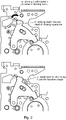
- Fig. 2 shows the intended motion for the example of the closing hook.
- the top figure shows the regular operation with the closing shaft rotation for releasing the closing hook.
- the closing hook can be operated in the opposite direction of normal release in order to keep the requiremets on force on the actuation low, as shown at the bottom.
- a small motion or micromotion of the latching elements can be used to identify a potential failure and indicate the need for a failure alarm or prevent a failure due to glueing of contacts.
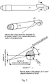
- Fig. 3 shows how such a motion can be generated, where the latching elements have been re-designed, introducing an eccentric element on the closing and/or opening shaft as shown as example in Fig. 3 for a closing shaft, but where a similar re-design applies to the opening shaft.
- the additional eccentric element 5 on the closing shaft is used to generate the necessary micromotion when the circuit breaker is in normal operating mode.
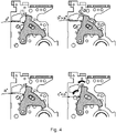
- Fig. 4 shows one example of a sequence of the micromotion and the use of the eccentricity on the closing shaft 1.
- the closing hook 2 contacts the closing shaft 1 and is in a latched position.
- the checking state as shown in the top right image, the closing shaft 1 is rotated in an opposite direction of the regular release direction, and the closing hook 2 is rotated and checked for its functioning in the latched position.
- the eccentricity of the closing shaft 1 forces the closing hook 2 to follow the shape in the contact zone and, by this, the closing hook 2 is rotated for a certain angular value, based on the eccentricity design.
- an additional sensor e.g.
- the rotation of the closing hook 2 can be detected.
- the closing shaft is rotated backwards to the original position and the closing hook 2 is following again, since it is driven by the closing spring forces towards the shaft. This is again the normal state where the closing hook 2 is resting on the closing shaft 1 in the latched position.
- the release of the losing hook is shown in the bottom right image, where the closing shaft 1 is rotated in the release direction, and the closing hook is released and the closing operation is started.
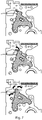
- Fig. 5 shows an example of an additional eccentric element on the opening shaft 3.
- an eccentric opening shaft 3 design is used in order to detect the functionality of the latching elements. Similar to the check on closing, as shown in the left image the opening latch is in a normal state with the opening hook 4 resting on the opening shaft 3 in the latched position. As shown in the right hand image, in the check state when the opening shaft 3 is rotated in an opposite direction to the normal release direction the opening hook 4 is rotated and checked for functioning in the latched position where the opening hook has been forced to undertake a small rotation. That motion can be detected with a sensor. Instead of using an additional sensor, the positive feedback or the actuating unit of the shaft (e.g.
- a sensor can be used to detect or monitor the force and/or torque required to perform the micromotion, and this can be evaluated against a normal, established, force and/or torque and this can be used to detect or establish the proper functioning of the latching elements.
- Fig. 6 shows another design of the eccentric shaft.
- the eccentricity is introduced in a way, that a rotation of the shaft in the same direction as the usual operating direction is introducing the motion on the latching hook.
- the additional eccentric element 6 on the closing shaft is used to generate the necessary micromotion when the circuit breaker is in normal operating mode.
- a 2-step-actuation of the shaft is utilized.
- the working sequence is shown in Fig. 7 .
- the closing hook 2 In normal state as shown in the top image the closing hook 2 is contacting the closing shaft 1, and is resting in its latched position.
- the closing shaft 2 In check mode, as shown in the centre image the closing shaft 2 is rotated for a certain value (x degrees) with a special type of 2-step actuator and, by this, pushing and rotating the closing hook 2.
- the actuator rotates the closing shaft 1 for the additional value (y degrees) and the actautor can release the circuit breaker to open.
Landscapes
- Refuge Islands, Traffic Blockers, Or Guard Fence (AREA)
- Breakers (AREA)
Description
- The present invention relates to actuators for a medium voltage circuit breaker.
-
EP2650892A1 describes that the device has closure elements and an opening located opposite to a closure actuating-element and an opening actuating-element. A mechanical connector comprises a part that is integrally connected with the closure elements. A retractable element is cooperated with an actuator that actuates the closure actuating-element in a retractable position to transmit a command to the closure element. An interlocking device is controlled by a selector. -
US5929405 describes that an electrical switching apparatus such as a power circuit breaker, network protector or switch has a self-supporting operating mechanism module including a cage formed by a pair of side plates rigidly clamped in spaced relation by spacers. The cage supports all of the operating mechanism components including a helical compression close spring mounted fully between the side plates and coupled to a cam member through a rocker in a manner which maintains the forces longitudinal to the spring. The cam member has a charging cam with a charge profile for compressing the close spring and a close profile through which the spring drives the cam member to effect a controlled release of stored energy to close the contacts of the apparatus. A close prop, spring biased to an unlatched position, is latched to secure the close spring in the charged state by a latch assembly reset by a reset lever separate from the close prop which in turn is reset by rotation of the cam member during charging. An interlock prevents release of the close spring when the contacts are closed or the trip release is actuated. An indicator actuated by a driver pivoted against the cam shaft snaps from a discharged to a charged indication as the close spring becomes fully charged and the driver drops into a notch created by a flat on the cam shaft. Rotating shafts are journalled solely in confronting apertures in the side plates. The cam shaft is captured between bushings seated in non-circular openings in the side plates thereby eliminating the need for any fasteners. -
WO2013/137846A1 describes a trip blocking apparatus of a circuit breaker exhibiting no trip at off functionality. It is described that the trip blocking apparatus effectively blocks tripping of a trip bar when the circuit breaker is in the off configuration. The trip blocking apparatus has a trip blocking arm and a blocking lever. A first projection of the blocking lever is configured to contact a handle arm, and a second projection is configured to interfere with the trip blocking arm to block tripping of the trip bar responsive to handle arm motion. - The checking of medium voltage (MV) and low voltage (LV) mechanical actuators for circuit breakers (CB) to establish that they are functioning correctly after a period of nonusage or in a "closed" state, usually is only possible through a regular actuation of the complete CB or equivalent application. checking of only the actuator with respect to its main latching elements and their proper functioning is not possible.
- There is a need to address this issue.
- Therefore, it would be advantageous to have means to check actuators for circuit breakers without having to activate the complete circuit breaker.
- The object of the present invention is solved with the subject matter of the independent claims, wherein further embodiments are incorporated in the dependent claims.
- In a first aspect, there is provided an actuator for a medium voltage circuit breaker, the actuator comprising:
- a closing shaft; and
- a closing hook.
- The closing shaft has a longitudinal axis. The closing shaft comprises an interaction region at an interaction location along the longitudinal axis. The closing shaft is configured to rotate about the longitudinal axis. In a first state the closing shaft is configured to be at a first rotational position, and the closing hook is configured to be in contact with the interaction region such that the closing hook cannot rotate in a first rotational direction. In a second state the closing shaft is configured to be at a second rotational position, and the closing hook is configured to rotate in the first rotational direction past the interaction region of the closing shaft. The actuator is configured to transition from the first state to a third state. In the transition from the first state to the third state the closing shaft is configured to rotate from the first rotational position to a third rotational position, and the closing hook is configured to be in contact with the interaction region such that the closing hook has been rotated in a second rotational direction opposite to the first rotational direction.
- In this manner, if the closing hook does not rotate in the second rotational direction as expected, for example requires more force to rotate, it can be determined that there is a problem with the actuator.
- It is to be noted that the actuator has applicability to low, medium and indeed high voltage applications, with that applicability extending beyond that for circuit breakers. Thus, other low, medium and high voltage systems that require actuation from closed to open states can make use of the actuator provided and described herein.
- According to the invention, a cross section of the closing shaft at the interaction region comprises a first dimension extending from the longitudinal axis to a first part of the outer surface of the closing shaft at a first angular position. The cross section of the closing shaft at the interaction region comprises a second dimension extending from the longitudinal axis to a second part of the outer surface of the closing shaft at a second angular position. The cross section of the closing shaft at the interaction region comprises a third dimension extending from the longitudinal axis to a third part of the outer surface of the closing shaft at a third angular position. The first dimension is greater than the second dimension and the third dimension is greater than the first dimension. In the first state the closing hook is configured to contact the interaction region of the closing shaft at the first part of the outer surface. In the second state an outer portion of the closing hook is configured to pass in proximity to the second part of the outer surface of the closing shaft in rotating in the first rotational direction past the interaction region of the closing shaft. In the third state, when the closing shaft is configured to be in the third rotational position the closing hook is configured to contact the interaction region of the closing shaft at the third part of the outer surface.
- In other words, an eccentricity is used on the closing shaft, that is used to perform a small motion / micro motion of latching elements for an actuator, providing a check function for the actuator.
- In an example, the actuator is configured to transition from the third state to the first state. In the transition from the third state to the first state the closing shaft is configured to rotate from the third rotational position to the first rotational position, and the closing hook is configured to be in contact with the interaction region such that the closing hook has been rotated in the first rotational direction.
- In this way, if the closing hook does not rotate back to the normal holding position as expected, it can be determined that there is a problem with the actuator.
- In an example, the actuator is configured to transition from the first state to the third state without entering the second state.
- In an example, the actuator is configured to transition from the third state to the first state without entering the second state,
- In an example, the closing shaft is configured to rotate in the first rotational direction when the actuator transitions from the first state to the second state.
- In an example, in the transition from the first state to the third state the closing shaft is configured to rotate in the second rotational direction to rotate from the first rotational position to the third rotational position.
- In an example, in the transition from the first state to the third state the closing shaft is configured to rotate in the first rotational direction to rotate from the first rotational position to the third rotational position.
- In an example, a sensor is configured to detect rotation of the closing hook in the second rotational direction when the closing shaft is configured to rotate from the first rotational position to the third rotational position.
- In an example, a sensor is configured to detect rotation of the closing hook in the first rotational direction when the closing shaft is configured to rotate from the third rotational position to the first rotational position.
- In an example, the same sensor is used to detect both rotations.
- In an example, at least one sensor is configured to measure a force and/or torque required to rotate the closing shaft.
- In an example, an actuating unit for the closing shaft is configured to detect rotation of the closing hook in the second rotational direction when the closing shaft is configured to rotate from the first rotational position to the third rotational position.
- In an example, the actuating unit for the closing shaft is configured to detect rotation of the closing hook in the first rotational direction when the closing shaft is configured to rotate from the third rotational position to the first rotational position.
- In a second aspect, there is provided an actuator for a medium voltage circuit breaker, the actuator comprising:
- an opening shaft; and
- an opening hook.
- The opening shaft has a longitudinal axis. The opening shaft comprises an interaction region at an interaction location along the longitudinal axis. The opening shaft is configured to rotate about the longitudinal axis. In a first state the opening shaft is configured to be at a first rotational position, and the opening hook is configured to be in contact with the interaction region such that the opening hook cannot rotate in a first rotational direction. In a second state the opening shaft is configured to be at a second rotational position, and the opening hook is configured to rotate in the first rotational direction past the interaction region of the opening shaft. The actuator is configured to transition from the first state to a third state. In the transition from the first state to the third state the opening shaft is configured to rotate from the first rotational position to a third rotational position, and the opening hook is configured to be in contact with the interaction region such that the opening hook has been rotated in a second rotational direction opposite to the first rotational direction.
- In this manner, if the opening hook does not rotate in the second rotational direction as expected, for example requires more force to rotate, it can be determined that there is a problem with the actuator.
- According to the invention, a cross section of the opening shaft at the interaction region comprises a first dimension extending from the longitudinal axis to a first part of the outer surface of the opening shaft at a first angular position. The cross section of the opening shaft at the interaction region comprises a second dimension extending from the longitudinal axis to a second part of the outer surface of the opening shaft at a second angular position. The cross section of the opening shaft at the interaction region comprises a third dimension extending from the longitudinal axis to a third part of the outer surface of the opening shaft at a third angular position. The first dimension is greater than the second dimension and the third dimension is greater than the first dimension. In the first state the opening hook is configured to contact the interaction region of the opening shaft at the first part of the outer surface. In the second state an outer portion of the opening hook is configured to pass in proximity to the second part of the outer surface of the opening shaft in rotating in the first rotational direction past the interaction region of the opening shaft. In the third state, when the opening shaft is configured to be in the third rotational position the opening hook is configured to contact the interaction region of the opening shaft at the third part of the outer surface. In other words, an eccentricity is used on the opening shaft, that is used to perform a small motion / micro motion of latching elements for an actuator, providing a check function for the actuator.
- In an example, the actuator is configured to transition from the third state to the first state. In the transition from the third state to the first state the opening shaft is configured to rotate from the third rotational position to the first rotational position, and the opening hook is configured to be in contact with the interaction region such that the opening hook has been rotated in the first rotational direction.
- In this way, if the opening hook does not rotate back to the normal holding position as expected, it can be determined that there is a problem with the actuator.
- In an example, the actuator is configured to transition from the first state to the third state without entering the second state.
- In an example, the actuator is configured to transition from the third state to the first state without entering the second state,
- In an example, the opening shaft is configured to rotate in the first rotational direction when the actuator transitions from the first state to the second state.
- In an example, in the transition from the first state to the third state the opening shaft is configured to rotate in the second rotational direction to rotate from the first rotational position to the third rotational position.
- In an example, in the transition from the first state to the third state the opening shaft is configured to rotate in the first rotational direction to rotate from the first rotational position to the third rotational position.
- In an example, a sensor is configured to detect rotation of the opening hook in the second direction when the opening shaft is configured to rotate from the first rotational position to the third rotational position.
- In an example, a the sensor is configured to detect rotation of the opening hook in the first direction when the opening shaft is configured to rotate from the third rotational position to the first rotational position.
- In an example, the same sensor is used to detect both rotations.
- In an example, at least one sensor is configured to measure a force and/or torque required to rotate the opening hook.
- In an example, an actuating unit for the opening shaft is configured to detect rotation of the opening hook in the second direction when the opening shaft is configured to rotate from the first rotational position to the third rotational position.
- In an example, the actuating unit for the opening shaft is configured to detect rotation of the opening hook in the first direction when the opening shaft is configured to rotate from the third rotational position to the first rotational position.
- In a third aspect, there is provided an actuator for a medium voltage circuit breaker, the actuator comprising:
- a closing shaft;
- a closing hook;
- an opening shaft; and
- an opening hook.
- The closing shaft has a longitudinal axis. The closing shaft comprises an interaction region at an interaction location along the longitudinal axis. The closing shaft is configured to rotate about the longitudinal axis. In a first state the closing shaft is configured to be at a first rotational position, wherein the closing hook is configured to be in contact with the interaction region such that the closing hook cannot rotate in a first rotational direction. In a second state the closing shaft is configured to be at a second rotational position, wherein the closing hook is configured to rotate in the first rotational direction past the interaction region of the closing shaft. The actuator is configured to transition from the first state to a third, wherein the closing shaft is configured to rotate from the first rotational position to a third rotational position, and wherein the closing hook is configured to be in contact with the interaction region such that the closing hook has been rotated in a second rotational direction opposite to the first rotational direction. The opening shaft has a longitudinal axis. The opening shaft comprises an interaction region at an interaction location along the longitudinal axis. The opening shaft is configured to rotate about the longitudinal axis. In a fourth state the opening shaft is configured to be at a first rotational position, wherein the opening hook is configured to be in contact with the interaction region such that the opening hook cannot rotate in the second rotational direction. In a fifth state the opening shaft is configured to be at a second rotational position, wherein the opening hook is configured to rotate in the second rotational direction past the interaction region of the opening shaft. The actuator is configured to transition from the fourth state to a sixth, wherein the opening shaft is configured to rotate from the first rotational position to a third rotational position, and wherein the opening hook is configured to be in contact with the interaction region such that the opening hook has been rotated in the first rotational direction.
- Exemplary embodiments will be described in the following with reference to the following drawings:
-
Fig. 1 shows an example of an actuator; -
Fig. 2 shows an example of an actuator; -
Fig. 3 shows an example of a closing shaft or an actuator; -
Fig. 4 shows an example of an actuator; -
Fig. 5 shows an example of an actuator; -
Fig. 6 shows an example of a closing shaft of an actuator; and -
Fig. 7 shows an example of an actuator. -
Figs. 1-7 show examples of actuators and relevant parts of those actuator. - One example relates to an actuator for a medium voltage circuit breaker. The actuator comprises a closing
shaft 1, and aclosing hook 2. The closing shaft has a longitudinal axis. The closing shaft comprises an interaction region at an interaction location along the longitudinal axis. The closing shaft is configured to rotate about the longitudinal axis. In a first state the closing shaft is configured to be at a first rotational position, and the closing hook is configured to be in contact with the interaction region such that the closing hook cannot rotate in a first rotational direction. In a second state the closing shaft is configured to be at a second rotational position, and the closing hook is configured to rotate in the first rotational direction past the interaction region of the closing shaft. Thus the second state involves the closing shaft moving from the first rotational position to the second rotational position thereby releasing the closing hook that can then rotate past the closing shaft. The actuator is configured to transition from the first state to a third state. In the transition from the first state to the third state the closing shaft is configured to rotate from the first rotational position to a third rotational position, and the closing hook is configured to be in contact with the interaction region such that the closing hook has been rotated in a second rotational direction opposite to the first rotational direction. - Thus, the actuator has a closing shaft that functions as a locking shaft for closing operation, and the actuator has a closing hook that functions as a latch for closing operation - a closing latch. The actuator is then configured to enable the operation of the actuator to be simply and conveniently established.
- According to the invention, a cross section of the closing shaft at the interaction region comprises a first dimension extending from the longitudinal axis to a first part of the outer surface of the closing shaft at a first angular position. The cross section of the closing shaft at the interaction region comprises a second dimension extending from the longitudinal axis to a second part of the outer surface of the closing shaft at a second angular position. The cross section of the closing shaft at the interaction region comprises a third dimension extending from the longitudinal axis to a third part of the outer surface of the closing shaft at a third angular position. The first dimension is greater than the second dimension and the third dimension is greater than the first dimension. In the first state the closing hook is configured to contact the interaction region of the closing shaft at the first part of the outer surface. In the second state an outer portion of the closing hook is configured to pass in proximity to the second part of the outer surface of the closing shaft in rotating in the first rotational direction past the interaction region of the closing shaft. In the third state, when the closing shaft is configured to be in the third rotational position the closing hook is configured to contact the interaction region of the closing shaft at the third part of the outer surface.
- According to an example, the actuator is configured to transition from the third state to the first state. In the transition from the third state to the first state the closing shaft is configured to rotate from the third rotational position to the first rotational position, and the closing hook is configured to be in contact with the interaction region such that the closing hook has been rotated in the first rotational direction. However, if the closing hook is not functioning correctly, it may not rotate back and this lack of rotation detected to determine that there is a problem with the actuator.
- According to an example, the actuator is configured to transition from the first state to the third state without entering the second state.
- According to an example, the actuator is configured to transition from the third state to the first state without entering the second state,
- According to an example, the closing shaft is configured to rotate in the first rotational direction when the actuator transitions from the first state to the second state.
- According to an example, in the transition from the first state to the third state the closing shaft is configured to rotate in the second rotational direction to rotate from the first rotational position to the third rotational position.
- According to an example, in the transition from the first state to the third state the closing shaft is configured to rotate in the first rotational direction to rotate from the first rotational position to the third rotational position.
- According to an example, a sensor is configured to detect rotation of the closing hook in the second rotational direction when the closing shaft is configured to rotate from the first rotational position to the third rotational position.
- According to an example, a sensor is configured to detect rotation of the closing hook in the first rotational direction when the closing shaft is configured to rotate from the third rotational position to the first rotational position.
- According to an example, the same sensor is configured to detect both rotations.
- According to an example, at least one sensor is configured to measure a force and/or torque required to rotate the closing shaft.
- According to an example, an actuating unit for the closing shaft is configured to detect rotation of the closing hook in the second rotational direction when the closing shaft is configured to rotate from the first rotational position to the third rotational position.
- According to an example, the actuating unit for the closing shaft is configured to detect rotation of the closing hook in the first rotational direction when the closing shaft is configured to rotate from the third rotational position to the first rotational position.
- One example relates to a an actuator for a medium voltage circuit breaker. The actuator comprises an
opening shaft 3, and an opening hook 4. The opening shaft has a longitudinal axis. The opening shaft comprises an interaction region at an interaction location along the longitudinal axis. The opening shaft is configured to rotate about the longitudinal axis. In a first state the opening shaft is configured to be at a first rotational position, and the opening hook is configured to be in contact with the interaction region such that the opening hook cannot rotate in a first rotational direction. In a second state the opening shaft is configured to be at a second rotational position, and the opening hook is configured to rotate in the first rotational direction past the interaction region of the opening shaft. Thus the second state involves the opening shaft moving from the first rotational position to the second rotational position thereby releasing the opening hook that can then rotate past the opening shaft. The actuator is configured to transition from the first state to a third state. In the transition from the first state to the third state the opening shaft is configured to rotate from the first rotational position to a third rotational position, and the opening hook is configured to be in contact with the interaction region such that the opening hook has been rotated in a second rotational direction opposite to the first rotational direction. - Thus, the actuator has an opening shaft that functions as a locking shaft for opening operation, and the actuator has an opening hook that functions as a latch for opening operation - an opening latch. The actuator is then configured to enable the operation of the actuator to be simply and conveniently established.
- It is to be noted that the first rotational direction referred to with respect this example can be in a different rotational direction to the first rotational direction referred to with respect to the the first exemplar actuator described with respect to the figures.
- According to the invention, a cross section of the opening shaft at the interaction region comprises a first dimension extending from the longitudinal axis to a first part of the outer surface of the opening shaft at a first angular position. The cross section of the opening shaft at the interaction region comprises a second dimension extending from the longitudinal axis to a second part of the outer surface of the opening shaft at a second angular position. The cross section of the opening shaft at the interaction region comprises a third dimension extending from the longitudinal axis to a third part of the outer surface of the opening shaft at a third angular position. The first dimension is greater than the second dimension and the third dimension is greater than the first dimension. In the first state the opening hook is configured to contact the interaction region of the opening shaft at the first part of the outer surface. In the second state an outer portion of the opening hook is configured to pass in proximity to the second part of the outer surface of the opening shaft in rotating in the first rotational direction past the interaction region of the opening shaft. In the third state, when the opening shaft is configured to be in the third rotational position the opening hook is configured to contact the interaction region of the opening shaft at the third part of the outer surface.
- According to an example, the actuator is configured to transition from the third state to the first state. In the transition from the third state to the first state the opening shaft is configured to rotate from the third rotational position to the first rotational position, and the opening hook is configured to be in contact with the interaction region such that the opening hook has been rotated in the first rotational direction. However, if the opening hook is not functioning correctly, it may not rotate back and this lack of rotation detected to determine that there is a problem with the actuator.
- According to an example, the actuator is configured to transition from the first state to the third state without entering the second state.
- According to an example, the actuator is configured to transition from the third state to the first state without entering the second state,
- According to an example, the opening shaft is configured to rotate in the first rotational direction when the actuator transitions from the first state to the second state.
- According to an example, in the transition from the first state to the third state the opening shaft is configured to rotate in the second rotational direction to rotate from the first rotational position to the third rotational position.
- According to an example, in the transition from the first state to the third state the opening shaft is configured to rotate in the first rotational direction to rotate from the first rotational position to the third rotational position.
- According to an example, a sensor is configured to detect rotation of the opening hook in the second direction when the opening shaft is configured to rotate from the first rotational position to the third rotational position.
- According to an example, a sensor is configured to detect rotation of the opening hook in the first direction when the opening shaft is configured to rotate from the third rotational position to the first rotational position.
- According to an example, the same sensor is configured to detect both rotations.
- According to an example, at least one sensor is configured to measure a force and/or torque required to rotate the opening hook.
- For example, a sensor can be used to indicate or establish the proper functioning of the actuator in the following manner. Associated with the opening hook, the next element in the internal kinematic chain is a so called "opening lever", where the opening hook is touching on the opposite side. This opening lever can therefore be moved, and an additional sensor on, or associated with this second component can be used to indicate the proper functioning of the actuator.
- According to an example, an actuating unit for the opening shaft is configured to detect rotation of the opening hook in the second direction when the opening shaft is configured to rotate from the first rotational position to the third rotational position.
- According to an example, the actuating unit for the opening shaft is configured to detect rotation of the opening hook in the first direction when the opening shaft is configured to rotate from the third rotational position to the first rotational position.
- One example relates to an actuator for a medium voltage circuit breaker. The actuator comprises a closing
shaft 1, aclosing hook 2, anopening shaft 3, and an opening hook 4. The closing shaft has a longitudinal axis. The closing shaft comprises an interaction region at an interaction location along the longitudinal axis. The closing shaft is configured to rotate about the longitudinal axis. In a first state the closing shaft is configured to be at a first rotational position, and the closing hook is configured to be in contact with the interaction region such that the closing hook cannot rotate in a first rotational direction. In a second state the closing shaft is configured to be at a second rotational position, wherein the closing hook is configured to rotate in the first rotational direction past the interaction region of the closing shaft. Thus the second state involves the closing shaft moving from the first rotational position to the second rotational position thereby releasing the closing hook that can then rotate past the closing shaft. The actuator is configured to transition from the first state to a third state. In the transition from the first state to the third state the closing shaft is configured to rotate from the first rotational position to a third rotational position, and the closing hook is configured to be in contact with the interaction region such that the closing hook has been rotated in a second rotational direction opposite to the first rotational direction; wherein, the opening shaft has a longitudinal axis. The opening shaft comprises an interaction region at an interaction location along the longitudinal axis. The opening shaft is configured to rotate about the longitudinal axis. In a fourth state the opening shaft is configured to be at a first rotational position, and the opening hook is configured to be in contact with the interaction region such that the opening hook cannot rotate in the second rotational direction. In a fifth state the opening shaft is configured to be at a second rotational position, and the opening hook is configured to rotate in the second rotational direction past the interaction region of the opening shaft. Thus the fifth state involves the opening shaft moving from the first rotational position to the second rotational position thereby releasing the opening hook that can then rotate past the closing shaft. The actuator is configured to transition from the fourth state to a sixth state. In the transition from the fourth state to the sixth state the opening shaft is configured to rotate from the first rotational position to a third rotational position, and the opening hook is configured to be in contact with the interaction region such that the opening hook has been rotated in the first rotational direction. - According to the invention, a cross section of the closing shaft at the interaction region comprises a first dimension extending from the longitudinal axis to a first part of the outer surface of the closing shaft at a first angular position. The cross section of the closing shaft at the interaction region comprises a second dimension extending from the longitudinal axis to a second part of the outer surface of the closing shaft at a second angular position. The cross section of the closing shaft at the interaction region comprises a third dimension extending from the longitudinal axis to a third part of the outer surface of the closing shaft at a third angular position. The first dimension of the closing shaft is greater than the second dimension of the closing shaft and the third dimension of the closing shaft is greater than the first dimension of the closing shaft. In the first state the closing hook is configured to contact the interaction region of the closing shaft at the first part of the outer surface. In the second state an outer portion of the closing hook is configured to pass in proximity to the second part of the outer surface of the closing shaft in rotating in the first rotational direction past the interaction region of the closing shaft. In the third state, when the closing shaft is configured to be in the third rotational position the closing hook is configured to contact the interaction region of the closing shaft at the third part of the outer surface.
- In an example, the actuator is configured to transition from the third state to the first state. In the transition from the third state to the first state the closing shaft is configured to rotate from the third rotational position to the first rotational position, and the closing hook is configured to be in contact with the interaction region such that the closing hook has been rotated in the first rotational direction. However, if the closing hook is not functioning correctly, it may not rotate back and this lack of rotation detected to determine that there is a problem with the actuator.
- In an example, the actuator is configured to transition from the first state to the third state without entering the second state.
- In an example, the actuator is configured to transition from the third state to the first state without entering the second state,
- In an example, the closing shaft is configured to rotate in the first rotational direction when the actuator transitions from the first state to the second state.
- In an example, in the transition from the first state to the third state the closing shaft is configured to rotate in the second rotational direction to rotate from the first rotational position to the third rotational position.
- In an example, in the transition from the first state to the third state the closing shaft is configured to rotate in the first rotational direction to rotate from the first rotational position to the third rotational position.
- In an example, a sensor is configured to detect rotation of the closing hook in the second direction when the closing shaft is configured to rotate from the first rotational position to the third rotational position.
- In an example, a sensor is configured to detect rotation of the closing hook in the first direction when the closing shaft is configured to rotate from the third rotational position to the first rotational position.
- In an example, the same sensor is configured to detect both rotations.
- In an example,an actuating unit for the closing shaft is configured to detect rotation of the closing hook in the second direction when the closing shaft is configured to rotate from the first rotational position to the third rotational position.
- In an example, the actuating unit for the closing shaft is configured to detect rotation of the closing hook in the first direction when the closing shaft is configured to rotate from the third rotational position to the first rotational position.
- In an example, a cross section of the opening shaft at the interaction region comprises a first dimension extending from the longitudinal axis to a first part of the outer surface of the opening shaft at a first angular position. The cross section of the opening shaft at the interaction region comprises a second dimension extending from the longitudinal axis to a second part of the outer surface of the opening shaft at a second angular position. The cross section of the opening shaft at the interaction region comprises a third dimension extending from the longitudinal axis to a third part of the outer surface of the opening shaft at a third angular position. The first dimension of the opening shaft is greater than the second dimension of the opening shaft and the third dimension of the opening shaft is greater than the first dimension of the opening shaft. In the fourth state the opening hook is configured to contact the interaction region of the opening shaft at the first part of the outer surface. In the fifth state an outer portion of the opening hook is configured to pass in proximity to the second part of the outer surface of the opening shaft in rotating in the second rotational direction past the interaction region of the opening shaft. In the sixth state, when the opening shaft is configured to be in the third rotational position the opening hook is configured to contact the interaction region of the opening shaft at the third part of the outer surface.
- In an example, the actuator is configured to transition from the sixth state to the fourth state, wherein the opening shaft is configured to rotate from the third rotational position to the first rotational position, wherein the opening hook is configured to be in contact with the interaction region such that the opening hook has been rotated in the second rotational direction. However, if the opening hook is not functioning correctly, it may not rotate back and this lack of rotation detected to determine that there is a problem with the actuator.
- In an example, the actuator is configured to transition from the fourth state to the sixth state without entering the fifth state.
- In an example, the actuator is configured to transition from the sixth state to the fourth state without entering the fifth state,
- In an example, the opening shaft is configured to rotate in the second rotational direction when the actuator transitions from the fourth state to the fifth state.
- In an example, in the transition from the fourth state to the sixth state the opening shaft is configured to rotate in the first rotational direction to rotate from the first rotational position to the third rotational position.
- In an example, in the transition from the fourth state to the sixth state the opening shaft is configured to rotate in the second rotational direction to rotate from the first rotational position to the third rotational position.
- In an example, a sensor is configured to detect rotation of the opening hook in the first direction when the opening shaft is configured to rotate from the first rotational position to the third rotational position.
- In an example a sensor is configured to detect rotation of the opening hook in the second rotational direction when the opening shaft is configured to rotate from the third rotational position to the first rotational position.
- In an example, the same sensor is configured to detect both rotations.
- In an example, an actuating unit for the opening shaft is configured to detect rotation of the opening hook in the first rotational direction when the opening shaft is configured to rotate from the first rotational position to the third rotational position.
- In an exymple, the actuating unit for the opening shaft is configured to detect rotation of the opening hook in the second rotational direction when the opening shaft is configured to rotate from the third rotational position to the first rotational position. Continuing with the figures, specific features are described that enable the latching elements for both closing an opening an actuator for a circuit breaker to be checked without having to activate the circuit breaker itself. However, the features described can be used to check if latching elements of actuator used for other purposes are functioning correctly, and reference to a circuit breaker is only exemplary.
- The control of functionality of todays available, mechanical spring drive actuator variants for MV and LV circuit breakers and comparable applications requires a regular operation of "close" and "open" of the circuit breaker, if the normal function of the actuator needs to be evaluated. This is mainly due to the used latching principles and the design of the actuator as a kinematik gear system, that is designed to reduce the high closing and opening spring forces with several linkage gear stages to a low force on the latching elements and actuation of those. In many of the use-cases, the actautor and its connected circuit breaker is in operating mode and resting in either "closed" or "open" position for longer time periods (up to years) without any operation. Customers or Service Personnel, who want to evaluate a proper actuator function, have no possibility to check by a continuous control of the actuator if it would operate on the next tripping signal, or if parts of the latching elements are sticking and not moving due to e.g. aging effects of metals (corrosion) or the lubricants (higher viscosity) or other damages coming from mechanical deformation. Of main interest are the latching elements, since they are the last elements in the kinematic chain of the linkage gear system and see the lowest actuation forces. The higher forces at the main kinematics of the actuator usually are not effected by aging and sticking, since the forces would immediately break or open such sticky contacts. Once the latching elements are moving, the system is able to operate as planned.
- The actuator described with respect to
Figs. 1-7 overcomes these issues, where functioning of the actuator can be established without operation of the "open" and "close" of the circuit breaker. -
Fig 1 shows as one example of mechanical actuator types the an actuator with details on the latching elements for closing (parts 1 and 2) and opening (parts 3 and 4). In working conditions, the shown latching elements are contacting and pushed together without any motion over the time of operation of the circuit breaker. Parts have been introduced enabling the latching elements for closing and opening of a mechanical spring drive actuator to be moved without releasing the actuator completely or fully operating the application. -
Fig. 2 shows the intended motion for the example of the closing hook. The top figure shows the regular operation with the closing shaft rotation for releasing the closing hook. For a continuous failure control, the closing hook can be operated in the opposite direction of normal release in order to keep the requiremets on force on the actuation low, as shown at the bottom. A small motion or micromotion of the latching elements can be used to identify a potential failure and indicate the need for a failure alarm or prevent a failure due to glueing of contacts. -
Fig. 3 shows how such a motion can be generated, where the latching elements have been re-designed, introducing an eccentric element on the closing and/or opening shaft as shown as example inFig. 3 for a closing shaft, but where a similar re-design applies to the opening shaft. The additionaleccentric element 5 on the closing shaft is used to generate the necessary micromotion when the circuit breaker is in normal operating mode. -
Fig. 4 shows one example of a sequence of the micromotion and the use of the eccentricity on the closingshaft 1. In normal operation as shown in the top left image, theclosing hook 2 contacts the closingshaft 1 and is in a latched position. In the checking state as shown in the top right image, the closingshaft 1 is rotated in an opposite direction of the regular release direction, and theclosing hook 2 is rotated and checked for its functioning in the latched position. The eccentricity of the closingshaft 1 forces theclosing hook 2 to follow the shape in the contact zone and, by this, theclosing hook 2 is rotated for a certain angular value, based on the eccentricity design. With an additional sensor (e.g. proximity sensor or angular sensor or a force or torque sensor for example at the position of the operating coil that detects the required force or torque to rotate the shaft) the rotation of theclosing hook 2 can be detected. After the check is performed, as shown in the bottom left image the closing shaft is rotated backwards to the original position and theclosing hook 2 is following again, since it is driven by the closing spring forces towards the shaft. This is again the normal state where theclosing hook 2 is resting on the closingshaft 1 in the latched position. The release of the losing hook is shown in the bottom right image, where the closingshaft 1 is rotated in the release direction, and the closing hook is released and the closing operation is started. -
Fig. 5 shows an example of an additional eccentric element on theopening shaft 3. Also for the opening hook 4, aneccentric opening shaft 3 design is used in order to detect the functionality of the latching elements. Similar to the check on closing, as shown in the left image the opening latch is in a normal state with the opening hook 4 resting on theopening shaft 3 in the latched position. As shown in the right hand image, in the check state when theopening shaft 3 is rotated in an opposite direction to the normal release direction the opening hook 4 is rotated and checked for functioning in the latched position where the opening hook has been forced to undertake a small rotation. That motion can be detected with a sensor. Instead of using an additional sensor, the positive feedback or the actuating unit of the shaft (e.g. coil), that reached its end-position during the check state, can be used in order to detect the proper function of the latching elements. Also, a sensor can be used to detect or monitor the force and/or torque required to perform the micromotion, and this can be evaluated against a normal, established, force and/or torque and this can be used to detect or establish the proper functioning of the latching elements. -
Fig. 6 shows another design of the eccentric shaft. In this variant of the closing shaft, the eccentricity is introduced in a way, that a rotation of the shaft in the same direction as the usual operating direction is introducing the motion on the latching hook. The additionaleccentric element 6 on the closing shaft is used to generate the necessary micromotion when the circuit breaker is in normal operating mode. - In this case, a 2-step-actuation of the shaft is utilized. The working sequence is shown in
Fig. 7 . In normal state as shown in the top image theclosing hook 2 is contacting the closingshaft 1, and is resting in its latched position. In check mode, as shown in the centre image the closingshaft 2 is rotated for a certain value (x degrees) with a special type of 2-step actuator and, by this, pushing and rotating theclosing hook 2. For the release of the hook as shown in the bottom image the actuator rotates the closingshaft 1 for the additional value (y degrees) and the actautor can release the circuit breaker to open.
Claims (21)
- An actuator for a medium voltage circuit breaker, the actuator comprising:- a closing shaft (1); and- a closing hook (2);wherein, the closing shaft has a longitudinal axis;wherein, the closing shaft comprises an interaction region at an interaction location along the longitudinal axis;wherein, the closing shaft is configured to rotate about the longitudinal axis;wherein, a cross section of the closing shaft at the interaction region comprises a first dimension extending from the longitudinal axis to a first part of the outer surface of the closing shaft at a first angular position;wherein, the cross section of the closing shaft at the interaction region comprises a second dimension extending from the longitudinal axis to a second part of the outer surface of the closing shaft at a second angular position;wherein, the cross section of the closing shaft at the interaction region comprises a third dimension extending from the longitudinal axis to a third part of the outer surface of the closing shaft at a third angular position;wherein, the first dimension is greater than the second dimension and the third dimension is greater than the first dimension;wherein, in a first state the closing shaft is configured to be at a first rotational position, wherein the closing hook is configured to be in contact with the interaction region such that the closing hook cannot rotate in a first rotational direction;wherein, in the first state the closing hook is configured to contact the interaction region of the closing shaft at the first part of the outer surface;wherein, in a second state the closing shaft is configured to be at a second rotational position, wherein the closing hook is configured to rotate in the first rotational direction past the interaction region of the closing shaft;wherein, in the second state an outer portion of the closing hook is configured to pass in proximity to the second part of the outer surface of the closing shaft in rotating in the first rotational direction past the interaction region of the closing shaft;wherein, the actuator is configured to transition from the first state to a third state, wherein the closing shaft is configured to rotate from the first rotational position to a third rotational position, wherein the closing hook is configured to be in contact with the interaction region such that the closing hook has been rotated in a second rotational direction opposite to the first rotational direction; andwherein, in the third state, when the closing shaft is configured to be in the third rotational position the closing hook is configured to contact the interaction region of the closing shaft at the third part of the outer surface.
- Actuator according to claim 1, wherein the actuator is configured to transition from the third state to the first state, wherein the closing shaft is configured to rotate from the third rotational position to the first rotational position, wherein the closing hook is configured to be in contact with the interaction region such that the closing hook has been rotated in the first rotational direction.
- Actuator according to any of claims 1-2, wherein, the actuator is configured to transition from the first state to the third state without entering the second state.
- Actuator according to any of claims 2-3, wherein the actuator is configured to transition from the third state to the first state without entering the second state,
- Actuator according to any of claims 1-4, wherein the closing shaft is configured to rotate in the first rotational direction when the actuator transitions from the first state to the second state.
- Actuator according to any of claims 1-5, wherein in the transition from the first state to the third state the closing shaft is configured to rotate in the second rotational direction to rotate from the first rotational position to the third rotational position.
- Actuator according to any of claims 1-5, wherein in the transition from the first state to the third state the closing shaft is configured to rotate in the first rotational direction to rotate from the first rotational position to the third rotational position.
- Actuator according to any of claims 1-7, wherein a sensor is configured to detect rotation of the closing hook in the second rotational direction when the closing shaft is configured to rotate from the first rotational position to the third rotational position; and/or the sensor is configured to detect rotation of the closing hook in the first rotational direction when the closing shaft is configured to rotate from the third rotational position to the first rotational position.
- Actuator according to any of claims 1-8, wherein at least one sensor is configured to measure a force and/or torque required to rotate the closing shaft.
- Actuator according to any of claims 1-9, wherein an actuating unit for the closing shaft is configured to detect rotation of the closing hook in the second rotational direction when the closing shaft is configured to rotate from the first rotational position to the third rotational position; and/or the actuating unit for the closing shaft is configured to detect rotation of the closing hook in the first rotational direction when the closing shaft is configured to rotate from the third rotational position to the first rotational position.
- An actuator for a medium voltage circuit breaker, the actuator comprising:- an opening shaft (3); and- an opening hook (4);wherein, the opening shaft has a longitudinal axis;wherein, the opening shaft comprises an interaction region at an interaction location along the longitudinal axis;wherein, the opening shaft is configured to rotate about the longitudinal axis;wherein, a cross section of the opening shaft at the interaction region comprises a first dimension extending from the longitudinal axis to a first part of the outer surface of the opening shaft at a first angular position;wherein, the cross section of the opening shaft at the interaction region comprises a second dimension extending from the longitudinal axis to a second part of the outer surface of the opening shaft at a second angular position;wherein, the cross section of the opening shaft at the interaction region comprises a third dimension extending from the longitudinal axis to a third part of the outer surface of the opening shaft at a third angular position;wherein, the first dimension is greater than the second dimension and the third dimension is greater than the first dimension;wherein, in a first state the opening shaft is configured to be at a first rotational position, wherein the opening hook is configured to be in contact with the interaction region such that the opening hook cannot rotate in a first rotational direction;wherein, in the first state the opening hook is configured to contact the interaction region of the opening shaft at the first part of the outer surface;wherein, in a second state the opening shaft is configured to be at a second rotational position, wherein the opening hook is configured to rotate in the first rotational direction past the interaction region of the opening shaft;wherein, in the second state an outer portion of the opening hook is configured to pass in proximity to the second part of the outer surface of the opening shaft in rotating in the first rotational direction past the interaction region of the opening shaft;wherein, the actuator is configured to transition from the first state to a third state, wherein the opening shaft is configured to rotate from the first rotational position to a third rotational position, wherein the opening hook is configured to be in contact with the interaction region such that the opening hook has been rotated in a second rotational direction opposite to the first rotational direction; andwherein, in the third state, when the opening shaft is configured to be in the third rotational position the opening hook is configured to contact the interaction region of the opening shaft at the third part of the outer surface.
- Actuator according to claim 11, wherein the actuator is configured to transition from the third state to the first state, wherein the opening shaft is configured to rotate from the third rotational position to the first rotational position, wherein the opening hook is configured to be in contact with the interaction region such that the opening hook has been rotated in the first rotational direction.
- Actuator according to any of claims 11-12, wherein, the actuator is configured to transition from the first state to the third state without entering the second state.
- Actuator according to any of claims 12-13, wherein the actuator is configured to transition from the third state to the first state without entering the second state,
- Actuator according to any of claims 11-14, wherein the opening shaft is configured to rotate in the first rotational direction when the actuator transitions from the first state to the second state.
- Actuator according to any of claims 11-15, wherein in the transition from the first state to the third state the opening shaft is configured to rotate in the second rotational direction to rotate from the first rotational position to the third rotational position.
- Actuator according to any of claims 11-15, wherein in the transition from the first state to the third state the opening shaft is configured to rotate in the first rotational direction to rotate from the first rotational position to the third rotational position.
- Actuator according to any of claims 11-17, wherein a sensor is configured to detect rotation of the opening hook in the second direction when the opening shaft is configured to rotate from the first rotational position to the third rotational position; and/or the sensor is configured to detect rotation of the opening hook in the first direction when the opening shaft is configured to rotate from the third rotational position to the first rotational position.
- Actuator according to any of claims 11-18, wherein at least one sensor is configured to measure a force and/or torque required to rotate the opening hook.
- Actuator according to any of claims 11-19, wherein an actuating unit for the opening shaft is configured to detect rotation of the opening hook in the second direction when the opening shaft is configured to rotate from the first rotational position to the third rotational position; and/or the actuating unit for the opening shaft is configured to detect rotation of the opening hook in the first direction when the opening shaft is configured to rotate from the third rotational position to the first rotational position.
- An actuator for a medium voltage circuit breaker, the actuator comprising:- a closing shaft (1);- a closing hook (2);- an opening shaft (3); and- an opening hook (4);wherein, the closing shaft has a longitudinal axis;wherein, the closing shaft comprises an interaction region at an interaction location along the longitudinal axis;wherein, the closing shaft is configured to rotate about the longitudinal axis;wherein, a cross section of the closing shaft at the interaction region comprises a first dimension extending from the longitudinal axis to a first part of the outer surface of the closing shaft at a first angular position;wherein, the cross section of the closing shaft at the interaction region comprises a second dimension extending from the longitudinal axis to a second part of the outer surface of the closing shaft at a second angular position;wherein, the cross section of the closing shaft at the interaction region comprises a third dimension extending from the longitudinal axis to a third part of the outer surface of the closing shaft at a third angular position;wherein, the first dimension is greater than the second dimension and the third dimension is greater than the first dimension;wherein, in a first state the closing shaft is configured to be at a first rotational position, wherein the closing hook is configured to be in contact with the interaction region such that the closing hook cannot rotate in a first rotational direction;wherein, in the first state the closing hook is configured to contact the interaction region of the closing shaft at the first part of the outer surface;wherein, in a second state the closing shaft is configured to be at a second rotational position, wherein the closing hook is configured to rotate in the first rotational direction past the interaction region of the closing shaft;wherein, in the second state an outer portion of the closing hook is configured to pass in proximity to the second part of the outer surface of the closing shaft in rotating in the first rotational direction past the interaction region of the closing shaft;wherein, the actuator is configured to transition from the first state to a third state, wherein the closing shaft is configured to rotate from the first rotational position to a third rotational position, wherein the closing hook is configured to be in contact with the interaction region such that the closing hook has been rotated in a second rotational direction opposite to the first rotational direction;wherein, in the third state, when the closing shaft is configured to be in the third rotational position the closing hook is configured to contact the interaction region of the closing shaft at the third part of the outer surface;wherein, the opening shaft has a longitudinal axis;wherein, the opening shaft comprises an interaction region at an interaction location along the longitudinal axis;wherein, the opening shaft is configured to rotate about the longitudinal axis;wherein, a cross section of the opening shaft at the interaction region comprises a first dimension extending from the longitudinal axis to a first part of the outer surface of the opening shaft at a first angular position;wherein, the cross section of the opening shaft at the interaction region comprises a second dimension extending from the longitudinal axis to a second part of the outer surface of the opening shaft at a second angular position;wherein, the cross section of the opening shaft at the interaction region comprises a third dimension extending from the longitudinal axis to a third part of the outer surface of the opening shaft at a third angular position;wherein, the first dimension is greater than the second dimension and the third dimension is greater than the first dimension;wherein, in a fourth state the opening shaft is configured to be at a first rotational position, wherein the opening hook is configured to be in contact with the interaction region such that the opening hook cannot rotate in the second rotational direction;wherein, in the fourth state the opening hook is configured to contact the interaction region of the opening shaft at the first part of the outer surface;wherein, in a fifth state the opening shaft is configured to be at a second rotational position, wherein the opening hook is configured to rotate in the second rotational direction past the interaction region of the opening shaft;wherein, in the fifth state an outer portion of the opening hook is configured to pass in proximity to the second part of the outer surface of the opening shaft in rotating in the second rotational direction past the interaction region of the opening shaft;wherein, the actuator is configured to transition from the fourth state to a sixth state, wherein the opening shaft is configured to rotate from the first rotational position to a third rotational position, wherein the opening hook is configured to be in contact with the interaction region such that the opening hook has been rotated in the first rotational direction; andwherein, in the sixth state, when the opening shaft is configured to be in the third rotational position the opening hook is configured to contact the interaction region of the opening shaft at the third part of the outer surface.
Priority Applications (2)
| Application Number | Priority Date | Filing Date | Title |
|---|---|---|---|
| EP19156490.5A EP3693985B1 (en) | 2019-02-11 | 2019-02-11 | Actuator for a medium voltage circuit breaker |
| CN202010085288.2A CN111554542B (en) | 2019-02-11 | 2020-02-10 | Actuator for medium voltage circuit breaker |
Applications Claiming Priority (1)
| Application Number | Priority Date | Filing Date | Title |
|---|---|---|---|
| EP19156490.5A EP3693985B1 (en) | 2019-02-11 | 2019-02-11 | Actuator for a medium voltage circuit breaker |
Publications (2)
| Publication Number | Publication Date |
|---|---|
| EP3693985A1 EP3693985A1 (en) | 2020-08-12 |
| EP3693985B1 true EP3693985B1 (en) | 2022-11-09 |
Family
ID=65408986
Family Applications (1)
| Application Number | Title | Priority Date | Filing Date |
|---|---|---|---|
| EP19156490.5A Active EP3693985B1 (en) | 2019-02-11 | 2019-02-11 | Actuator for a medium voltage circuit breaker |
Country Status (2)
| Country | Link |
|---|---|
| EP (1) | EP3693985B1 (en) |
| CN (1) | CN111554542B (en) |
Cited By (1)
| Publication number | Priority date | Publication date | Assignee | Title |
|---|---|---|---|---|
| EP4411770A1 (en) | 2023-02-02 | 2024-08-07 | Abb Schweiz Ag | Monitoring system for a mechanically driven circuit breaker |
Family Cites Families (16)
| Publication number | Priority date | Publication date | Assignee | Title |
|---|---|---|---|---|
| US5929405A (en) * | 1998-05-07 | 1999-07-27 | Eaton Corporation | Interlock for electrical switching apparatus with stored energy closing |
| KR101060786B1 (en) * | 2009-11-19 | 2011-08-30 | 엘에스산전 주식회사 | Lock of circuit breaker |
| US8718968B2 (en) * | 2010-08-31 | 2014-05-06 | Abb Technology Ag | Circuit breaker interrupter travel curve estimation |
| EP2579291B1 (en) * | 2011-10-06 | 2014-06-04 | ABB Technology AG | Coil actuator for a switching device and related switching device |
| CN202549706U (en) * | 2012-02-28 | 2012-11-21 | 上海西门子开关有限公司 | Spring operating mechanism and vacuum circuit breaker |
| EP2826050B1 (en) * | 2012-03-12 | 2017-04-26 | Siemens Aktiengesellschaft | Circuit breaker trip blocking apparatus, systems and methods of operation |
| FR2989216B1 (en) * | 2012-04-10 | 2015-02-20 | Schneider Electric Ind Sas | DEVICE FOR CONTROLLING A MEDIUM VOLTAGE ELECTRICAL EQUIPMENT AND APPARATUS CONTROLLED THEREBY |
| CN102723229B (en) * | 2012-06-29 | 2014-11-05 | 浙江国源电气有限公司 | Manual operation mechanism of outdoor permanent magnetic high-voltage vacuum circuit breaker |
| CN203774167U (en) * | 2014-03-14 | 2014-08-13 | 厦门凯能电力科技有限公司 | Miniature vacuum-circuit-breaker spring operation mechanism |
| CN203799952U (en) * | 2014-04-11 | 2014-08-27 | 辽宁易德电气有限公司 | Opening and closing induced current vacuum switch device |
| CN103903905B (en) * | 2014-04-11 | 2016-07-06 | 辽宁易德实业集团有限公司 | Opening and closing induction current vacuum switch device |
| CN205595268U (en) * | 2016-04-25 | 2016-09-21 | 广州霍斯通电气股份有限公司 | Vacuum circuit breaker's spring operating mechanism and vacuum circuit breaker |
| CN206602069U (en) * | 2017-01-13 | 2017-10-31 | 浙江巨力电气有限公司 | A kind of permanent magnetic spring integrated mechanism of outdoor high-voltage alternating-current vacuum breaker |
| CN107017116A (en) * | 2017-04-20 | 2017-08-04 | 日升集团有限公司 | Double-switching-on position spring operating mechanism |
| CN207705096U (en) * | 2017-11-27 | 2018-08-07 | 浙江兴田电气有限公司 | A kind of outdoor high-pressure permanent magnetism vacuum circuit breaker |
| CN108428589B (en) * | 2018-01-24 | 2020-05-26 | 宁波舜利高压开关科技有限公司 | High-efficiency transmission connecting rod structure of operating mechanism |
-
2019
- 2019-02-11 EP EP19156490.5A patent/EP3693985B1/en active Active
-
2020
- 2020-02-10 CN CN202010085288.2A patent/CN111554542B/en active Active
Cited By (1)
| Publication number | Priority date | Publication date | Assignee | Title |
|---|---|---|---|---|
| EP4411770A1 (en) | 2023-02-02 | 2024-08-07 | Abb Schweiz Ag | Monitoring system for a mechanically driven circuit breaker |
Also Published As
| Publication number | Publication date |
|---|---|
| CN111554542A (en) | 2020-08-18 |
| CN111554542B (en) | 2023-07-28 |
| EP3693985A1 (en) | 2020-08-12 |
Similar Documents
| Publication | Publication Date | Title |
|---|---|---|
| US9685280B2 (en) | Switchgear operating mechanism | |
| CN201540860U (en) | Electric switch equipment, loading component and interlocking component thereof | |
| CN105609386B (en) | Control and protective switching device | |
| EP2110835B1 (en) | Readiness for closing indicator for circuit breakers | |
| EP2015340B1 (en) | Time delay output apparatus for circuit breaker | |
| CN104508788B (en) | For the assisted actuators of the electric device of protection circuit | |
| CN102208290A (en) | Electrical switching apparatus and close latch interlock assembly therefor | |
| EP3693985B1 (en) | Actuator for a medium voltage circuit breaker | |
| EP2472547B1 (en) | Locking device for use with a circuit breaker and method of assembly | |
| US9275807B2 (en) | Interlock system for switchgear | |
| US8624145B2 (en) | Indicator device of a circuit breaker | |
| EP3340270B1 (en) | Auxiliary switch | |
| US8253517B2 (en) | Full-protection circuit breaker | |
| CN1881495B (en) | Actuators for electrical switching devices with rotatable locking devices | |
| WO2016103063A1 (en) | Tripping unit of a switching assembly | |
| CN211404383U (en) | Grounding switch | |
| EP4503084A1 (en) | Bidirectional operation mechanism for switching device and switching device assembly | |
| CN110021494A (en) | Transmission system and switchgear for grounding switch in switch cabinet | |
| CN109416997A (en) | Middle piezoelectricity way switch or medium voltage breaker | |
| EP3319102B1 (en) | Indication device of electric switch | |
| US8993912B2 (en) | Switching apparatus | |
| CN100386838C (en) | Electromagnetic circuit breaker | |
| CN116487230A (en) | Indication mechanism of circuit breaker and circuit breaker | |
| DE102019220444B4 (en) | Remote operator and parameterization procedure | |
| CN205264650U (en) | Circuit breaker anti -bouncing device |
Legal Events
| Date | Code | Title | Description |
|---|---|---|---|
| PUAI | Public reference made under article 153(3) epc to a published international application that has entered the european phase |
Free format text: ORIGINAL CODE: 0009012 |
|
| STAA | Information on the status of an ep patent application or granted ep patent |
Free format text: STATUS: THE APPLICATION HAS BEEN PUBLISHED |
|
| AK | Designated contracting states |
Kind code of ref document: A1 Designated state(s): AL AT BE BG CH CY CZ DE DK EE ES FI FR GB GR HR HU IE IS IT LI LT LU LV MC MK MT NL NO PL PT RO RS SE SI SK SM TR |
|
| AX | Request for extension of the european patent |
Extension state: BA ME |
|
| STAA | Information on the status of an ep patent application or granted ep patent |
Free format text: STATUS: REQUEST FOR EXAMINATION WAS MADE |
|
| 17P | Request for examination filed |
Effective date: 20210114 |
|
| RBV | Designated contracting states (corrected) |
Designated state(s): AL AT BE BG CH CY CZ DE DK EE ES FI FR GB GR HR HU IE IS IT LI LT LU LV MC MK MT NL NO PL PT RO RS SE SI SK SM TR |
|
| GRAP | Despatch of communication of intention to grant a patent |
Free format text: ORIGINAL CODE: EPIDOSNIGR1 |
|
| STAA | Information on the status of an ep patent application or granted ep patent |
Free format text: STATUS: GRANT OF PATENT IS INTENDED |
|
| INTG | Intention to grant announced |
Effective date: 20220603 |
|
| GRAS | Grant fee paid |
Free format text: ORIGINAL CODE: EPIDOSNIGR3 |
|
| GRAA | (expected) grant |
Free format text: ORIGINAL CODE: 0009210 |
|
| STAA | Information on the status of an ep patent application or granted ep patent |
Free format text: STATUS: THE PATENT HAS BEEN GRANTED |
|
| AK | Designated contracting states |
Kind code of ref document: B1 Designated state(s): AL AT BE BG CH CY CZ DE DK EE ES FI FR GB GR HR HU IE IS IT LI LT LU LV MC MK MT NL NO PL PT RO RS SE SI SK SM TR |
|
| RAP3 | Party data changed (applicant data changed or rights of an application transferred) |
Owner name: ABB SCHWEIZ AG |
|
| REG | Reference to a national code |
Ref country code: GB Ref legal event code: FG4D |
|
| REG | Reference to a national code |
Ref country code: CH Ref legal event code: EP Ref country code: AT Ref legal event code: REF Ref document number: 1530927 Country of ref document: AT Kind code of ref document: T Effective date: 20221115 |
|
| REG | Reference to a national code |
Ref country code: DE Ref legal event code: R096 Ref document number: 602019021584 Country of ref document: DE |
|
| REG | Reference to a national code |
Ref country code: IE Ref legal event code: FG4D |
|
| REG | Reference to a national code |
Ref country code: LT Ref legal event code: MG9D |
|
| REG | Reference to a national code |
Ref country code: NL Ref legal event code: MP Effective date: 20221109 |
|
| REG | Reference to a national code |
Ref country code: AT Ref legal event code: MK05 Ref document number: 1530927 Country of ref document: AT Kind code of ref document: T Effective date: 20221109 |
|
| PG25 | Lapsed in a contracting state [announced via postgrant information from national office to epo] |
Ref country code: SE Free format text: LAPSE BECAUSE OF FAILURE TO SUBMIT A TRANSLATION OF THE DESCRIPTION OR TO PAY THE FEE WITHIN THE PRESCRIBED TIME-LIMIT Effective date: 20221109 Ref country code: PT Free format text: LAPSE BECAUSE OF FAILURE TO SUBMIT A TRANSLATION OF THE DESCRIPTION OR TO PAY THE FEE WITHIN THE PRESCRIBED TIME-LIMIT Effective date: 20230309 Ref country code: NO Free format text: LAPSE BECAUSE OF FAILURE TO SUBMIT A TRANSLATION OF THE DESCRIPTION OR TO PAY THE FEE WITHIN THE PRESCRIBED TIME-LIMIT Effective date: 20230209 Ref country code: LT Free format text: LAPSE BECAUSE OF FAILURE TO SUBMIT A TRANSLATION OF THE DESCRIPTION OR TO PAY THE FEE WITHIN THE PRESCRIBED TIME-LIMIT Effective date: 20221109 Ref country code: FI Free format text: LAPSE BECAUSE OF FAILURE TO SUBMIT A TRANSLATION OF THE DESCRIPTION OR TO PAY THE FEE WITHIN THE PRESCRIBED TIME-LIMIT Effective date: 20221109 Ref country code: ES Free format text: LAPSE BECAUSE OF FAILURE TO SUBMIT A TRANSLATION OF THE DESCRIPTION OR TO PAY THE FEE WITHIN THE PRESCRIBED TIME-LIMIT Effective date: 20221109 Ref country code: AT Free format text: LAPSE BECAUSE OF FAILURE TO SUBMIT A TRANSLATION OF THE DESCRIPTION OR TO PAY THE FEE WITHIN THE PRESCRIBED TIME-LIMIT Effective date: 20221109 |
|
| PG25 | Lapsed in a contracting state [announced via postgrant information from national office to epo] |
Ref country code: RS Free format text: LAPSE BECAUSE OF FAILURE TO SUBMIT A TRANSLATION OF THE DESCRIPTION OR TO PAY THE FEE WITHIN THE PRESCRIBED TIME-LIMIT Effective date: 20221109 Ref country code: PL Free format text: LAPSE BECAUSE OF FAILURE TO SUBMIT A TRANSLATION OF THE DESCRIPTION OR TO PAY THE FEE WITHIN THE PRESCRIBED TIME-LIMIT Effective date: 20221109 Ref country code: LV Free format text: LAPSE BECAUSE OF FAILURE TO SUBMIT A TRANSLATION OF THE DESCRIPTION OR TO PAY THE FEE WITHIN THE PRESCRIBED TIME-LIMIT Effective date: 20221109 Ref country code: IS Free format text: LAPSE BECAUSE OF FAILURE TO SUBMIT A TRANSLATION OF THE DESCRIPTION OR TO PAY THE FEE WITHIN THE PRESCRIBED TIME-LIMIT Effective date: 20230309 Ref country code: HR Free format text: LAPSE BECAUSE OF FAILURE TO SUBMIT A TRANSLATION OF THE DESCRIPTION OR TO PAY THE FEE WITHIN THE PRESCRIBED TIME-LIMIT Effective date: 20221109 Ref country code: GR Free format text: LAPSE BECAUSE OF FAILURE TO SUBMIT A TRANSLATION OF THE DESCRIPTION OR TO PAY THE FEE WITHIN THE PRESCRIBED TIME-LIMIT Effective date: 20230210 |
|
| PG25 | Lapsed in a contracting state [announced via postgrant information from national office to epo] |
Ref country code: NL Free format text: LAPSE BECAUSE OF FAILURE TO SUBMIT A TRANSLATION OF THE DESCRIPTION OR TO PAY THE FEE WITHIN THE PRESCRIBED TIME-LIMIT Effective date: 20221109 |
|
| PG25 | Lapsed in a contracting state [announced via postgrant information from national office to epo] |
Ref country code: SM Free format text: LAPSE BECAUSE OF FAILURE TO SUBMIT A TRANSLATION OF THE DESCRIPTION OR TO PAY THE FEE WITHIN THE PRESCRIBED TIME-LIMIT Effective date: 20221109 Ref country code: RO Free format text: LAPSE BECAUSE OF FAILURE TO SUBMIT A TRANSLATION OF THE DESCRIPTION OR TO PAY THE FEE WITHIN THE PRESCRIBED TIME-LIMIT Effective date: 20221109 Ref country code: EE Free format text: LAPSE BECAUSE OF FAILURE TO SUBMIT A TRANSLATION OF THE DESCRIPTION OR TO PAY THE FEE WITHIN THE PRESCRIBED TIME-LIMIT Effective date: 20221109 Ref country code: DK Free format text: LAPSE BECAUSE OF FAILURE TO SUBMIT A TRANSLATION OF THE DESCRIPTION OR TO PAY THE FEE WITHIN THE PRESCRIBED TIME-LIMIT Effective date: 20221109 Ref country code: CZ Free format text: LAPSE BECAUSE OF FAILURE TO SUBMIT A TRANSLATION OF THE DESCRIPTION OR TO PAY THE FEE WITHIN THE PRESCRIBED TIME-LIMIT Effective date: 20221109 |
|
| REG | Reference to a national code |
Ref country code: DE Ref legal event code: R097 Ref document number: 602019021584 Country of ref document: DE |
|
| PG25 | Lapsed in a contracting state [announced via postgrant information from national office to epo] |
Ref country code: SK Free format text: LAPSE BECAUSE OF FAILURE TO SUBMIT A TRANSLATION OF THE DESCRIPTION OR TO PAY THE FEE WITHIN THE PRESCRIBED TIME-LIMIT Effective date: 20221109 Ref country code: AL Free format text: LAPSE BECAUSE OF FAILURE TO SUBMIT A TRANSLATION OF THE DESCRIPTION OR TO PAY THE FEE WITHIN THE PRESCRIBED TIME-LIMIT Effective date: 20221109 |
|
| PLBE | No opposition filed within time limit |
Free format text: ORIGINAL CODE: 0009261 |
|
| STAA | Information on the status of an ep patent application or granted ep patent |
Free format text: STATUS: NO OPPOSITION FILED WITHIN TIME LIMIT |
|
| PG25 | Lapsed in a contracting state [announced via postgrant information from national office to epo] |
Ref country code: MC Free format text: LAPSE BECAUSE OF FAILURE TO SUBMIT A TRANSLATION OF THE DESCRIPTION OR TO PAY THE FEE WITHIN THE PRESCRIBED TIME-LIMIT Effective date: 20221109 |
|
| REG | Reference to a national code |
Ref country code: CH Ref legal event code: PL |
|
| 26N | No opposition filed |
Effective date: 20230810 |
|
| REG | Reference to a national code |
Ref country code: BE Ref legal event code: MM Effective date: 20230228 |
|
| GBPC | Gb: european patent ceased through non-payment of renewal fee |
Effective date: 20230211 |
|
| PG25 | Lapsed in a contracting state [announced via postgrant information from national office to epo] |
Ref country code: LU Free format text: LAPSE BECAUSE OF NON-PAYMENT OF DUE FEES Effective date: 20230211 Ref country code: LI Free format text: LAPSE BECAUSE OF NON-PAYMENT OF DUE FEES Effective date: 20230228 Ref country code: CH Free format text: LAPSE BECAUSE OF NON-PAYMENT OF DUE FEES Effective date: 20230228 |
|
| PG25 | Lapsed in a contracting state [announced via postgrant information from national office to epo] |
Ref country code: SI Free format text: LAPSE BECAUSE OF FAILURE TO SUBMIT A TRANSLATION OF THE DESCRIPTION OR TO PAY THE FEE WITHIN THE PRESCRIBED TIME-LIMIT Effective date: 20221109 |
|
| REG | Reference to a national code |
Ref country code: IE Ref legal event code: MM4A |
|
| PG25 | Lapsed in a contracting state [announced via postgrant information from national office to epo] |
Ref country code: GB Free format text: LAPSE BECAUSE OF NON-PAYMENT OF DUE FEES Effective date: 20230211 |
|
| PG25 | Lapsed in a contracting state [announced via postgrant information from national office to epo] |
Ref country code: IE Free format text: LAPSE BECAUSE OF NON-PAYMENT OF DUE FEES Effective date: 20230211 Ref country code: GB Free format text: LAPSE BECAUSE OF NON-PAYMENT OF DUE FEES Effective date: 20230211 |
|
| PG25 | Lapsed in a contracting state [announced via postgrant information from national office to epo] |
Ref country code: BE Free format text: LAPSE BECAUSE OF NON-PAYMENT OF DUE FEES Effective date: 20230228 |
|
| PG25 | Lapsed in a contracting state [announced via postgrant information from national office to epo] |
Ref country code: BG Free format text: LAPSE BECAUSE OF FAILURE TO SUBMIT A TRANSLATION OF THE DESCRIPTION OR TO PAY THE FEE WITHIN THE PRESCRIBED TIME-LIMIT Effective date: 20221109 |
|
| PG25 | Lapsed in a contracting state [announced via postgrant information from national office to epo] |
Ref country code: BG Free format text: LAPSE BECAUSE OF FAILURE TO SUBMIT A TRANSLATION OF THE DESCRIPTION OR TO PAY THE FEE WITHIN THE PRESCRIBED TIME-LIMIT Effective date: 20221109 |
|
| PGFP | Annual fee paid to national office [announced via postgrant information from national office to epo] |
Ref country code: DE Payment date: 20250218 Year of fee payment: 7 |
|
| PGFP | Annual fee paid to national office [announced via postgrant information from national office to epo] |
Ref country code: FR Payment date: 20250224 Year of fee payment: 7 |
|
| PGFP | Annual fee paid to national office [announced via postgrant information from national office to epo] |
Ref country code: IT Payment date: 20250224 Year of fee payment: 7 |
|
| PG25 | Lapsed in a contracting state [announced via postgrant information from national office to epo] |
Ref country code: CY Free format text: LAPSE BECAUSE OF FAILURE TO SUBMIT A TRANSLATION OF THE DESCRIPTION OR TO PAY THE FEE WITHIN THE PRESCRIBED TIME-LIMIT; INVALID AB INITIO Effective date: 20190211 |
|
| PG25 | Lapsed in a contracting state [announced via postgrant information from national office to epo] |
Ref country code: HU Free format text: LAPSE BECAUSE OF FAILURE TO SUBMIT A TRANSLATION OF THE DESCRIPTION OR TO PAY THE FEE WITHIN THE PRESCRIBED TIME-LIMIT; INVALID AB INITIO Effective date: 20190211 |
|
| PG25 | Lapsed in a contracting state [announced via postgrant information from national office to epo] |
Ref country code: TR Free format text: LAPSE BECAUSE OF FAILURE TO SUBMIT A TRANSLATION OF THE DESCRIPTION OR TO PAY THE FEE WITHIN THE PRESCRIBED TIME-LIMIT Effective date: 20221109 |