EP4411485A1 - Container - Google Patents
Container Download PDFInfo
- Publication number
- EP4411485A1 EP4411485A1 EP22876589.7A EP22876589A EP4411485A1 EP 4411485 A1 EP4411485 A1 EP 4411485A1 EP 22876589 A EP22876589 A EP 22876589A EP 4411485 A1 EP4411485 A1 EP 4411485A1
- Authority
- EP
- European Patent Office
- Prior art keywords
- shutter
- cap
- toner
- rotational axis
- pack
- Prior art date
- Legal status (The legal status is an assumption and is not a legal conclusion. Google has not performed a legal analysis and makes no representation as to the accuracy of the status listed.)
- Pending
Links
Images













Classifications
-
- B—PERFORMING OPERATIONS; TRANSPORTING
- B41—PRINTING; LINING MACHINES; TYPEWRITERS; STAMPS
- B41J—TYPEWRITERS; SELECTIVE PRINTING MECHANISMS, i.e. MECHANISMS PRINTING OTHERWISE THAN FROM A FORME; CORRECTION OF TYPOGRAPHICAL ERRORS
- B41J2/00—Typewriters or selective printing mechanisms characterised by the printing or marking process for which they are designed
- B41J2/005—Typewriters or selective printing mechanisms characterised by the printing or marking process for which they are designed characterised by bringing liquid or particles selectively into contact with a printing material
- B41J2/01—Ink jet
- B41J2/17—Ink jet characterised by ink handling
- B41J2/175—Ink supply systems ; Circuit parts therefor
-
- B—PERFORMING OPERATIONS; TRANSPORTING
- B41—PRINTING; LINING MACHINES; TYPEWRITERS; STAMPS
- B41J—TYPEWRITERS; SELECTIVE PRINTING MECHANISMS, i.e. MECHANISMS PRINTING OTHERWISE THAN FROM A FORME; CORRECTION OF TYPOGRAPHICAL ERRORS
- B41J2/00—Typewriters or selective printing mechanisms characterised by the printing or marking process for which they are designed
- B41J2/005—Typewriters or selective printing mechanisms characterised by the printing or marking process for which they are designed characterised by bringing liquid or particles selectively into contact with a printing material
- B41J2/01—Ink jet
- B41J2/17—Ink jet characterised by ink handling
- B41J2/175—Ink supply systems ; Circuit parts therefor
- B41J2/17503—Ink cartridges
- B41J2/17536—Protection of cartridges or parts thereof, e.g. tape
- B41J2/1754—Protection of cartridges or parts thereof, e.g. tape with means attached to the cartridge, e.g. protective cap
-
- B—PERFORMING OPERATIONS; TRANSPORTING
- B65—CONVEYING; PACKING; STORING; HANDLING THIN OR FILAMENTARY MATERIAL
- B65B—MACHINES, APPARATUS OR DEVICES FOR, OR METHODS OF, PACKAGING ARTICLES OR MATERIALS; UNPACKING
- B65B7/00—Closing containers or receptacles after filling
- B65B7/16—Closing semi-rigid or rigid containers or receptacles not deformed by, or not taking-up shape of, contents, e.g. boxes or cartons
- B65B7/28—Closing semi-rigid or rigid containers or receptacles not deformed by, or not taking-up shape of, contents, e.g. boxes or cartons by applying separate preformed closures, e.g. lids, covers
- B65B7/2835—Closing semi-rigid or rigid containers or receptacles not deformed by, or not taking-up shape of, contents, e.g. boxes or cartons by applying separate preformed closures, e.g. lids, covers applying and rotating preformed threaded caps
-
- B—PERFORMING OPERATIONS; TRANSPORTING
- B65—CONVEYING; PACKING; STORING; HANDLING THIN OR FILAMENTARY MATERIAL
- B65D—CONTAINERS FOR STORAGE OR TRANSPORT OF ARTICLES OR MATERIALS, e.g. BAGS, BARRELS, BOTTLES, BOXES, CANS, CARTONS, CRATES, DRUMS, JARS, TANKS, HOPPERS, FORWARDING CONTAINERS; ACCESSORIES, CLOSURES, OR FITTINGS THEREFOR; PACKAGING ELEMENTS; PACKAGES
- B65D41/00—Caps, e.g. crown caps or crown seals, i.e. members having parts arranged for engagement with the external periphery of a neck or wall defining a pouring opening or discharge aperture; Protective cap-like covers for closure members, e.g. decorative covers of metal foil or paper
- B65D41/02—Caps or cap-like covers without lines of weakness, tearing strips, tags, or like opening or removal devices
- B65D41/04—Threaded or like caps or cap-like covers secured by rotation
-
- B—PERFORMING OPERATIONS; TRANSPORTING
- B65—CONVEYING; PACKING; STORING; HANDLING THIN OR FILAMENTARY MATERIAL
- B65D—CONTAINERS FOR STORAGE OR TRANSPORT OF ARTICLES OR MATERIALS, e.g. BAGS, BARRELS, BOTTLES, BOXES, CANS, CARTONS, CRATES, DRUMS, JARS, TANKS, HOPPERS, FORWARDING CONTAINERS; ACCESSORIES, CLOSURES, OR FITTINGS THEREFOR; PACKAGING ELEMENTS; PACKAGES
- B65D47/00—Closures with filling and discharging, or with discharging, devices
- B65D47/04—Closures with discharging devices other than pumps
- B65D47/06—Closures with discharging devices other than pumps with pouring spouts or tubes; with discharge nozzles or passages
- B65D47/12—Closures with discharging devices other than pumps with pouring spouts or tubes; with discharge nozzles or passages having removable closures
- B65D47/122—Threaded caps
-
- B—PERFORMING OPERATIONS; TRANSPORTING
- B65—CONVEYING; PACKING; STORING; HANDLING THIN OR FILAMENTARY MATERIAL
- B65D—CONTAINERS FOR STORAGE OR TRANSPORT OF ARTICLES OR MATERIALS, e.g. BAGS, BARRELS, BOTTLES, BOXES, CANS, CARTONS, CRATES, DRUMS, JARS, TANKS, HOPPERS, FORWARDING CONTAINERS; ACCESSORIES, CLOSURES, OR FITTINGS THEREFOR; PACKAGING ELEMENTS; PACKAGES
- B65D47/00—Closures with filling and discharging, or with discharging, devices
- B65D47/04—Closures with discharging devices other than pumps
- B65D47/06—Closures with discharging devices other than pumps with pouring spouts or tubes; with discharge nozzles or passages
- B65D47/12—Closures with discharging devices other than pumps with pouring spouts or tubes; with discharge nozzles or passages having removable closures
- B65D47/14—Closures with discharging devices other than pumps with pouring spouts or tubes; with discharge nozzles or passages having removable closures and closure-retaining means
- B65D47/142—Closures with discharging devices other than pumps with pouring spouts or tubes; with discharge nozzles or passages having removable closures and closure-retaining means for threaded caps
-
- G—PHYSICS
- G03—PHOTOGRAPHY; CINEMATOGRAPHY; ANALOGOUS TECHNIQUES USING WAVES OTHER THAN OPTICAL WAVES; ELECTROGRAPHY; HOLOGRAPHY
- G03G—ELECTROGRAPHY; ELECTROPHOTOGRAPHY; MAGNETOGRAPHY
- G03G15/00—Apparatus for electrographic processes using a charge pattern
- G03G15/06—Apparatus for electrographic processes using a charge pattern for developing
- G03G15/08—Apparatus for electrographic processes using a charge pattern for developing using a solid developer, e.g. powder developer
- G03G15/0822—Arrangements for preparing, mixing, supplying or dispensing developer
- G03G15/0865—Arrangements for supplying new developer
-
- G—PHYSICS
- G03—PHOTOGRAPHY; CINEMATOGRAPHY; ANALOGOUS TECHNIQUES USING WAVES OTHER THAN OPTICAL WAVES; ELECTROGRAPHY; HOLOGRAPHY
- G03G—ELECTROGRAPHY; ELECTROPHOTOGRAPHY; MAGNETOGRAPHY
- G03G15/00—Apparatus for electrographic processes using a charge pattern
- G03G15/06—Apparatus for electrographic processes using a charge pattern for developing
- G03G15/08—Apparatus for electrographic processes using a charge pattern for developing using a solid developer, e.g. powder developer
- G03G15/0822—Arrangements for preparing, mixing, supplying or dispensing developer
- G03G15/0865—Arrangements for supplying new developer
- G03G15/0874—Arrangements for supplying new developer non-rigid containers, e.g. foldable cartridges, bags
-
- G—PHYSICS
- G03—PHOTOGRAPHY; CINEMATOGRAPHY; ANALOGOUS TECHNIQUES USING WAVES OTHER THAN OPTICAL WAVES; ELECTROGRAPHY; HOLOGRAPHY
- G03G—ELECTROGRAPHY; ELECTROPHOTOGRAPHY; MAGNETOGRAPHY
- G03G15/00—Apparatus for electrographic processes using a charge pattern
- G03G15/06—Apparatus for electrographic processes using a charge pattern for developing
- G03G15/08—Apparatus for electrographic processes using a charge pattern for developing using a solid developer, e.g. powder developer
- G03G15/0822—Arrangements for preparing, mixing, supplying or dispensing developer
- G03G15/0877—Arrangements for metering and dispensing developer from a developer cartridge into the development unit
- G03G15/0881—Sealing of developer cartridges
- G03G15/0886—Sealing of developer cartridges by mechanical means, e.g. shutter, plug
-
- B—PERFORMING OPERATIONS; TRANSPORTING
- B41—PRINTING; LINING MACHINES; TYPEWRITERS; STAMPS
- B41J—TYPEWRITERS; SELECTIVE PRINTING MECHANISMS, i.e. MECHANISMS PRINTING OTHERWISE THAN FROM A FORME; CORRECTION OF TYPOGRAPHICAL ERRORS
- B41J2/00—Typewriters or selective printing mechanisms characterised by the printing or marking process for which they are designed
- B41J2/005—Typewriters or selective printing mechanisms characterised by the printing or marking process for which they are designed characterised by bringing liquid or particles selectively into contact with a printing material
- B41J2/01—Ink jet
- B41J2/17—Ink jet characterised by ink handling
- B41J2/175—Ink supply systems ; Circuit parts therefor
- B41J2/17503—Ink cartridges
- B41J2/17513—Inner structure
- B41J2002/17516—Inner structure comprising a collapsible ink holder, e.g. a flexible bag
-
- G—PHYSICS
- G03—PHOTOGRAPHY; CINEMATOGRAPHY; ANALOGOUS TECHNIQUES USING WAVES OTHER THAN OPTICAL WAVES; ELECTROGRAPHY; HOLOGRAPHY
- G03G—ELECTROGRAPHY; ELECTROPHOTOGRAPHY; MAGNETOGRAPHY
- G03G2215/00—Apparatus for electrophotographic processes
- G03G2215/06—Developing structures, details
- G03G2215/066—Toner cartridge or other attachable and detachable container for supplying developer material to replace the used material
- G03G2215/0682—Bag-type non-rigid container
-
- G—PHYSICS
- G03—PHOTOGRAPHY; CINEMATOGRAPHY; ANALOGOUS TECHNIQUES USING WAVES OTHER THAN OPTICAL WAVES; ELECTROGRAPHY; HOLOGRAPHY
- G03G—ELECTROGRAPHY; ELECTROPHOTOGRAPHY; MAGNETOGRAPHY
- G03G2215/00—Apparatus for electrophotographic processes
- G03G2215/06—Developing structures, details
- G03G2215/066—Toner cartridge or other attachable and detachable container for supplying developer material to replace the used material
- G03G2215/0692—Toner cartridge or other attachable and detachable container for supplying developer material to replace the used material using a slidable sealing member, e.g. shutter
Definitions
- the present invention relates to a container for use with an image forming apparatus.
- an image forming apparatus of an electrophotographic type forms an image by transferring a toner image, formed on a surface of a photosensitive drum, onto a transfer material as a transfer medium.
- a toner supplying type for example, a process cartridge type or a toner supplying (replenishing) type has been known.
- the process cartridge type is a type in which the photosensitive drum and a developing (developer) container are integrally assembled as a process cartridge and in which the process cartridge is exchanged with a new one when toner runs out.
- the toner supplying type is a type in which when the toner runs out, toner is newly supplied (replenished) to a developing container.
- Japanese Laid-Open Patent Application No. 2021-26199 an image forming apparatus in which the toner is supplied to the developing container by using a toner pouch mountable to a mounting portion provided on the developing container is disclosed.
- the image forming apparatus has been required by a user to employ various using manners such as the above-described process cartridge type, the above-described toner supplying type, and the like.
- the present invention aims to provide a form of a container.
- the present invention is a container for use with an image forming apparatus and for accommodating a content of powder or a liquid, the container comprising: an accommodating portion configured to accommodate the content; an end portion including a discharging portion which includes a discharge opening for permitting discharge of the content to an outside of the container and a passage configured so that the content passes through the passage toward the discharge opening, and including a shutter configured to be movable relative to the discharging portion between a shielding position where the shutter shields the discharge opening and an open position where the shutter opens the discharge opening; and a cap mounted to the end portion so as to cover at least a part of the end portion and configured to be dismounted from the end portion by being rotated relative to the end portion.
- the present invention is a container for use with an image forming apparatus and for accommodating a content of powder or a liquid
- the container comprising: an accommodating portion configured to accommodate the content; an end portion including a discharging portion which includes a discharge opening for permitting discharge of the content to an outside of the container and a passage configured so that the content passes through the passage toward the discharge opening, and including a shutter configured to be movable relative to the discharging portion between a shielding position where the shutter shields the discharge opening and an open position where the shutter opens the discharge opening; and a cap mounted to the shutter so as to cover at least a part of the end portion.
- the present invention is a toner container comprising: a toner accommodating portion configured to accommodate toner; a nozzle communicating with the toner accommodating portion and aligned with the toner accommodating portion in a first direction, the nozzle being provided with an opening forming a part of a discharging passage for permitting discharge of the toner to an outside of the toner container; a shutter configured to move between an open position where the shutter opens the opening and a closed position where the shutter closes the opening; and a cap mounted to the shutter so as to cover at least a part of the shutter and configured to engage with the shutter and to disengage with the shutter, wherein the opening of the nozzle is provided at a side surface extending along the first direction of the nozzle, and wherein in a second direction perpendicular to the first direction, the shutter is provided outside the side surface of the nozzle.
- the present invention is a toner container comprising: a toner accommodating portion configured to accommodate toner; a nozzle communicating with the toner accommodating portion and aligned with the toner accommodating portion in a first direction, the nozzle being provided with an opening forming a part of a discharging passage for permitting discharge of the toner to an outside of the toner container; a shutter configured to move between an open position where the shutter opens the opening and a closed position where the shutter closes the opening; and a cap detachably mounted to the shutter so as to cover at least a part of the shutter, wherein the cap is configured so that by rotation of the cap relative to the shutter about a rotational axis extending in the first direction, the cap engages with the shutter and disengages with the shutter.
- Part (a) of Figure 1 is a schematic view showing a structure of an image forming apparatus 1 according to this embodiment.
- Part (b) of Figure 1 is a perspective view showing the structure of the image forming apparatus 1.
- Figure 2 is a perspective view showing an openable member 83 and a supplying opening 32a.
- the image forming apparatus 1 is a monochromatic printer for forming an image on a recording material P on the basis of image information inputted from an external device.
- various sheet materials different in material including papers such as plain paper and thick paper, a plastic film such as a sheet for an overhead projector, special-shaped sheets such as an envelope and index paper, a cloth, and the like are included.
- the image forming apparatus 1 includes, as shown in parts (a) and (b) of Figure 1 , an apparatus main assembly 400, a reading device (apparatus) 200 supported so as to be openable and closable relative to the apparatus main assembly 400, and an operating portion 300 mounted to an outer casing surface of the apparatus main assembly 400.
- the apparatus main assembly 400 includes an image forming portion 10 for forming a toner image on the recording material, a feeding portion 60 for feeding the recording material to the image forming portion 10, a fixing portion 70 for fixing the toner image, formed by the image forming portion 10, on the recording material, and a discharging roller pair 80.
- the image forming portion 10 includes a scanner unit 11, a process unit 20 of an electrophotographic type, and a transfer roller 12 for transferring the toner image, formed on a photosensitive drum 21 of the process unit 20, onto the recording material.
- the process unit 20 includes the photosensitive drum 21, a charging roller 22 disposed at a periphery of the photosensitive drum 21, a pre-exposure device 23, and a developing device 30 including a developing roller 31.
- the photosensitive drum 21 is a photosensitive member molded in a cylindrical shape.
- the photosensitive drum 21 in this embodiment includes, on a drum-shaped base material molded with aluminum, a photosensitive layer formed with a negatively chargeable organic photosensitive member. Further, the photosensitive drum 21 is rotationally driven at a predetermined process speed in a predetermined direction (clockwise direction in the figure) by a motor.
- the charging roller 22 contacts the photosensitive drum 21 at a predetermined press-contact force and forms a charging portion. Further, a desired charging voltage is applied to the charging roller 22 by a high charging voltage power source, so that the charging roller 22 electrically charges a surface of the photosensitive drum 21 uniformly to a predetermined potential. In this embodiment, the photosensitive drum 21 is charged to a negative polarity by the charging roller 22.
- the pre-exposure device 23 discharges (removes) a surface potential of the photosensitive drum 21, at a position in front of the charging portion in order to generate stable electric discharge at the charging portion.
- the scanner unit 11 irradiates the photosensitive drum 21, by using a polygonal mirror, with laser light corresponding to image information inputted from the external device or the reading device 200, so that the surface of the photosensitive drum 21 is subjected to scanning exposure. By this light exposure, an electrostatic latent image depending on the image information is formed on the surface of the photosensitive drum 21.
- the scanner unit 11 is not limited to a laser scanner device, but for example, an LED exposure device including an LED array in which a plurality of LEDs are arranged along a longitudinal direction of the photosensitive drum 21 may be employed.
- the developing device 30 includes the developing roller 31 for carrying a developer, a developing container 32 which is a casing for the developing device 30, and a supplying roller 33 capable of supplying the developer to the developing roller 31.
- the developing roller 31 and the supplying roller 33 are rotatably supported by the developing container 32. Further, the developing roller 31 is disposed at an opening of the developing container 32 so as to oppose the photosensitive drum 21.
- the supplying roller 33 rotatably contacts the developing roller 31, and toner as a content accommodated in the developing container 32 is applied onto the surface of the developing roller 31 by the supplying roller 33.
- the supplying roller 33 is not necessarily be required.
- the developing device 30 in this embodiment uses a contact development type as a development type. That is, a toner layer carried on the developing roller 31 contacts the photosensitive drum 21 at a developing portion (developing region) where the photosensitive drum 21 and the developing roller 31 oppose each other.
- a developing voltage is applied by a high developing voltage power source.
- the toner carried on the developing roller 31 is transferred from the developing roller 31 onto the drum surface in accordance with a potential distribution of the surface of the photosensitive drum 21, so that the electrostatic latent image is developed into a toner image.
- a reversal development type is employed. That is, the toner image is formed by deposition of the toner on a surface region of the photosensitive drum 21 attenuated in charge amount by being exposed to light in an exposure step after being charged in a charging step.
- the toner which is 6 [ ⁇ m] in particle size and of which normal charge polarity is a negative polarity is used.
- a polymerization toner formed by a polymerization method as an example is employed.
- the toner in this embodiment is a so-called non-magnetic one-component developer which does not contain a magnetic component and in which the toner is carried on the developing roller 31 principally by an intermolecular force or an electrostatic force (mirror force).
- a one-component developer containing the magnetic component may also be used.
- an additive for example, wax or silica fine particles for adjusting flowability and charging performance of the toner is contained in addition to toner particles in some cases.
- a two-component developer constituted by non-magnetic toner and a magnetic carrier may also be used as the developer carrying member.
- the developer carrying member for example, a cylindrical developing sleeve inside of which a magnet is disposed is used.
- the developing container 32 is provided with an accommodating portion 36 for accommodating the toner and a stirring member 34 provided inside the accommodating portion 36.
- the stirring member 34 is rotated by being driven by an unshown motor, and thus stirs the toner in the developing container 32 and sends the toner toward the developing roller 31 and the supplying roller 33. Further, the stirring member 34 has a function of circulating the toner, peeled off from the developing roller 31 without being used for the development, in the developing container and of uniformizing the toner in the developing container.
- the stirring member 34 is not limited to a rotatable form.
- a stirring member in a swingable form may also be employed.
- a developing blade 35 for regulating an amount of the toner carried on the developing roller 31 is disposed at an opening of the developing container 32 where the developing roller 31 is disposed.
- the toner supplied to the surface of the developing roller 31 passes through an opposing portion to the developing blade 35 with rotation of the developing roller 31, so that the toner is uniformly formed in a thin layer and is charged to the negative polarity by triboelectric charge.
- a feeding portion 60 includes, as shown in parts (a) and (b) of Figure 1 , a front door 61 supported so as to be openable and closable by the apparatus main assembly 400, a tray portion 62, an intermediary plate 63, a tray spring 64, and a pick-up roller 65.
- the tray portion 62 constitutes a bottom of a recording material accommodating space which appears by opening the front door 61, and the intermediary plate 63 is supported by the tray portion 62 so as to be capable of being raised and lowered.
- the tray spring 64 urges the intermediary plate 63 upward and presses the recording materials P, stacked on the intermediary plate 63, against the pick-up roller 65.
- the front door 61 closes the recording material accommodating space in a state in which the front door 61 is closed relative to the apparatus main assembly 400, and supports the recording materials P together with the tray portion 62 and the intermediary plate 63 in a state in which the front door 61 is opened relative to the apparatus main assembly 400.
- the fixing portion 70 is of a heat fixing type in which an image fixing process is performed by heating and melting the toner on the recording material.
- the fixing portion 70 includes a fixing film 71, a fixing heater such as a ceramic heater for heating the fixing film 71, a thermistor for measuring a temperature of the fixing heater, and a pressing roller 72 press-contacting the fixing film 71.
- an image forming operation of the image forming apparatus 1 will be described.
- an instruction of image formation is inputted to the image forming apparatus 1, on the basis of the image information inputted from an external computer connected to the image forming apparatus 1 or from the reading device 200, an image forming process by the image forming portion 10 is started.
- the scanner unit 11 emits the laser light toward the photosensitive drum 21 on the basis of the inputted image information.
- the photosensitive drum 21 is charged in advance by the charging roller 22, and is irradiated with the laser light, so that the electrostatic latent image is formed on the photosensitive drum 21.
- this electrostatic latent image is developed by the developing roller 31, so that the toner image is formed on the photosensitive drum 21.
- the pick-up roller 65 of the feeding portion 60 sends the recording material P supported by the front door 61, the tray portion 62, and the intermediary plate 63.
- the recording material P is fed to a registration roller pair 15 by the pick-up roller 65, and is abutted against a nip of the registration roller pair 15, so that oblique movement of the recording material P is corrected.
- the registration roller pair 15 is driven by being timed to a transfer timing of the toner image, and is conveyed toward a transfer nip formed by a transfer roller 12 and the photosensitive drum 21.
- a transfer voltage is applied from a high transfer voltage power source, so that the toner image carried on the photosensitive drum 21 is transferred onto the recording material P conveyed by the registration roller pair 15.
- the recording material P onto which the toner image is transferred is conveyed to the fixing portion 70, where the toner image is heated and pressed when the recording material P passes through a nip between the fixing film 71 and the pressing roller 72 of the fixing portion 70.
- toner particles are melted and are thereafter fixed, so that the toner image is fixed on the recording material P.
- the recording material P passed through the fixing portion 70 is discharged to an outside of the image forming apparatus 1 (outside of the printer) by a discharging roller pair 80, so that the discharged recording materials P are stacked on a discharge tray 81 formed at an upper portion of the apparatus main assembly 400.
- the discharge tray 81 is inclined upward toward a downstream in a discharging direction of the recording material, and the recording material discharged on the discharge tray 81 slides down on the discharge tray 81, so that a trailing end of the recording material is aligned by a restricting surface 84.
- the reading device 200 includes a reading unit 201 in which an unshown reading portion is built, and a platen (pressure plate) 202 supported by the reading unit 201 so as to be openable and closable. At an upper surface of the reading unit 201, an original supporting platen glass 203 which permits transmission of light emitted from the reading portion and on which an original is to be placed.
- the user places the original on the original supporting platen glass 203 in a state in which the platen 202 is opened. Then, the platen 202 is closed and thus a positional deviation of the original on the original supporting platen glass 203 is prevented, so that a reading instruction is outputted to the image forming apparatus 1 by operating the operating portion 300, for example.
- the reading portion in the reading unit 201 reciprocates in a sub-scan direction, i.e., a left-right direction in a state in which the user faces the operating portion 300 of the image forming apparatus 1 on a front (surface) side.
- the reading portion receives light reflected by the original by a light receiving portion while emitting light from a light emitting portion toward the original, and photoelectrically converts the light, so that the reading portion reads the image of the original.
- a front-rear direction, the left-right direction, and an up-down direction are defined.
- a top cover 82 is provided, and at an upper surface of the top cover 82, the discharge tray 81 is formed. As shown in part (b) of Figure 1 and Figure 2 , the openable member 83 is supported by the top cover 82 so as to be openable and closable about a rotation shaft 83a extending in the front-rear direction. On the discharge tray 81 of the top cover 82, an opening 82a which opens upward is formed.
- the openable member 83 is constituted so as to be movable between a closed position where the openable member 83 covers a supplying opening 32a so that a toner pack 100 cannot be mounted to the developing container 32 and an open position where the supplying opening 32a is exposed so that the toner pack 100 can be mounted to the developing container 32.
- the toner pack 100 is moved in a mounting direction M and is detachably mounted to the supplying opening 32a.
- the openable member 83 functions as a part of the discharge tray 81 in the closed position.
- the openable member 83 and the opening 82a are formed on a left(-hand) side of the discharge tray 81. Further, the openable member 83 is opened in a left(-hand) direction by being hooked with user's finger(s) from a groove portion 82b provided on the top cover 82.
- the openable member 83 is formed in a substantially L-shape along a shape of the top cover 82.
- the opening 82a of the discharge tray 81 opens so that the supplying opening 32a for toner supply formed at the upper portion of the developing container 32 is exposed, and the openable member 83 is opened, so that the user can access to the supplying opening 32a.
- a type (direct supply type) in which the user supplies the toner from the toner pack 100 (see, parts (a) and (b) of Figure 1 ), filled with the toner for supply, to the developing device 30 kept in a state in which the developing device 30 is mounted in the image forming apparatus 1 is employed.
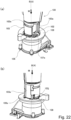
- the toner pack 100 is exposed to the outside at least at a part thereof in a state in which the toner pack 100 is mounted to the mounting portion 106 (see, parts (a) and (b) of Figure 22 ).
- the image forming apparatus 1 and the toner pack 100 constitute an image forming system 1000.
- the mounting portion 106 is a unit for mounting the toner pack 100 including the supplying opening 32a and is provided in the image forming apparatus 1 (see, Figure 2 ).
- Part (a) of Figure 3 is an exploded perspective view of the mounting portion 106.
- Part (b) of Figure 3 is an exploded perspective view of the mounting portion 106 as viewed from a direction different from the direction in part (a) of Figure 3 .
- Part (a) of Figure 4 and part (a) of Figure 5 are a perspective view showing an outer appearance of the mounting portion 106 and a schematic view of the mounting portion 106 as viewed in the mounting direction M, respectively, when an operating lever 108 is in a closed position.
- Part (b) of Figure 4 and part (b) of Figure 5 are a perspective view showing an outer appearance of the mounting portion 106 and a schematic view of the mounting portion 106 as viewed in the mounting direction M, respectively, when the operating lever 108 is in an open position.
- Part (a) of Figure 6 is a perspective view of a apparatus-side shutter 109 as viewed from an upstream side of the mounting direction M.
- Part (b) of Figure 6 is a perspective view of the apparatus-side shutter 109 different in point of view from part (a) of Figure 6 .
- Part (a) of Figure 7 is a perspective view of a cover 110 as viewed from a downstream side of the mounting direction M.
- Part (b) of Figure 7 is a perspective view of the cover 110 as viewed from an upstream side of the mounting direction M.
- Part (a) of Figure 8 is a sectional view showing the mounting portion 106, and part (b) of Figure 8 is a sectional view showing a 8B-8B cross section of part (a) of Figure 8 .
- the mounting portion 106 includes a main body base portion 2, and the main body base portion 2 includes a first frame 107, a second frame 117, and the cover 110.
- the cover 110 and the second frame 117 are fixed to the first frame 107.
- the cover 110 includes a portion-to-be-engaged 110h engaged with an engaging portion 107b of a positioning portion 107a of the first frame 107 so as not to be rotated about a rotational axis B relative to the first frame 107.
- a cut-away portion 110k is provided, and the cut-away portion 110k is provided with a first restricting surface 110c and a second restricting surface 110d.
- the first restricting surface 110c and the second restricting surface 110d are provided so as to oppose each other with respect to a circumferential direction about the rotational axis B.
- first frame 107, the cover 110, and the second frame 117 may be integrally constituted, not as separate members.
- the second frame 117 is provided with an apparatus-side opening 117a, and the apparatus-side opening 117a communicates with an accommodating portion 36 (see, part (a) of Figure 1 ) of the developing container 32.
- Each of the operating lever 108 and the apparatus-side shutter 109 is mounted to the main body base portion 2 so as to be rotatable about the rotational axis B.
- the first frame 107 is provided with the positioning portion 107a.
- the positioning portion 107a projects inward than an inner peripheral surface 107c about the rotational axis B of the first frame 107 in a radial direction r of a virtual circle VC about the rotational axis B.
- the operating lever 108 as an operating portion is provided with a drive transmitting portion 108a and an operating portion 108b.
- a user is capable of rotating the operating lever 108 about the rotational axis B relative to the main body base portion 2 by operating the operating portion 108b.
- the drive transmitting portion 108a as a portion-to-be-engaged and a first portion-to-be-engaged is a projected portion projected inward than an inner peripheral surface about the rotational axis B of the operating lever 108 in the radial direction r of the phantom circle VC about the rotational axis B, as shown in part (a) of Figure 3 .
- the apparatus-side shutter 109 as a main apparatus shutter includes an inner peripheral surface 109h, a receiving opening 109a provided in the inner peripheral surface 109h and for receiving the toner from the toner pack 100, and a bottom 109b.
- the apparatus-side shutter 109 further includes a center boss 109d provided on the bottom 109b, a pack contact surface 109g, a rib-to-be-restricted 109c, and a portion 109e to which drive is transmitted and which is provided on the inner peripheral surface 109h.
- the portion 109e to which drive is transmitted, as a second portion-to-be-engaged is a projected portion projected inward in the radial direction r of the virtual circle VC about the rotational axis B as shown in part (b) of Figure 6 .
- an apparatus-side seal 111 is applied so as to surround the receiving opening 109a (see, part (b) of Figure 4 ).
- the apparatus-side shutter 109 is constituted so as to take a shielding position as a second shielding position and an open position as a second open position relative to the main body base portion 2.
- the apparatus-side shutter 109 is, as shown in parts (a) and (b) of Figure 6 , rotated in an arrow K direction from the shielding position toward the open position and rotated in an arrow L direction from the open position toward the shielding position.
- these arrow K direction and arrow L direction are similar to arrow K direction and arrow L direction, respectively, of the pack-side shutter 103 shown in part (a) of Figure 11 .
- the receiving opening 109a in the shielding position, the receiving opening 109a is shielded by the apparatus-side seal 111 and the cover 110, and in the open position, the receiving opening 109a is opened without being covered by the cover 110. That is, the receiving opening 109a does not communicate with the apparatus-side opening 117a of the second frame 117 when the apparatus-side shutter 109 is positioned in the shielding position, and communicates with the apparatus-side opening 117a of the second frame 117 when the apparatus-side shutter 109 is positioned in the shielding position.
- the apparatus-side shutter 109 is positioned in the shielding position, and at this time, the receiving opening 109a of the apparatus-side shutter 109 does not communicate with the apparatus-side opening 117a of the second frame 117. Further, in part (b) of Figure 4 and part (b) of Figure 5 , the apparatus-side shutter 109 is positioned in the open position, and at this time, the receiving opening 109a of the apparatus-side shutter 109 communicates with the apparatus-side opening 117a of the second frame 117. The apparatus-side shutter 109 is moved to the open position, whereby the toner can be replenished (supplied) from the toner pack 100 to the accommodating portion 36 of the developing container 32 through the receiving opening 109a.
- the operating lever 108 and the apparatus-side shutter 109 are not drive-connected to each other, and therefore, even when the operating lever 108 is operated in a state in which the toner pack is not mounted, the apparatus-side shutter 109 is not rotated.
- the apparatus-side shutter 109 is constituted so as to be rotatable about the center boss 109d by engaging a large-diameter portion 109d1 of the center boss 109d with a cylindrical portion 110j of the cover 110.
- the rib-to-be-restricted 109c provided on the bottom 109b of the apparatus-side shutter 109 is positioned between the first restricting surface 110c and the second restricting surface 110d of the cover 110.
- the apparatus-side shutter 109 is rotatable only in movable range of the rib-to-be-restricted 109c between the first restricting surface 110c and the second restricting surface 110d.
- the apparatus-side shutter 109 is restricted in rotation range between the shielding position and the open position by the first restricting surface 110c and the second restricting surface 110d of the cover 110.
- the apparatus-side shutter 109 positioned in the shielding position cannot be rotated in the arrow L direction, i.e., a direction opposite to a direction toward the open position.
- the toner pack 100 is mounted on the above-described mounting portion 106.
- Part (a) of Figure 9 is side view of the toner pack 100 when the pack-side shutter 103 is in the shielding position.
- Part (b) of Figure 9 is a side view of the toner pack 100 when the pack-side shutter 103 is in the open position.
- Figure 10 is a exploded perspective view showing the toner pack 100 when the pack-side shutter 103.
- the toner pack 100 includes, as shown in part (a) of Figure 9 to Figure 10 , a pouch 101 accommodating the toner, a nozzle connected to the pouch 101, and the pack-side shutter 103.
- the nozzle 102 and the pack-side shutter 103 are connected to the pouch 101 and constitute a portion-to-be-mounted 700 mounted to the mounting portion 106.
- the pouch 101 as an accommodating portion and a toner accommodating portion has flexibility, and is provided on one end side of the toner pack 100 with respect to an axial direction D1 (first direction) which is a direction of a rotational axis A of the pack-side shutter 103. That is, the pouch 101 and the nozzle 102 are arranged in the axial direction D1.
- the rotational axis A coincides with the rotational axis B of the apparatus-side shutter 109 when the toner pack 100 is mounted on the mounting portion 106, and therefore, in the following, both directions of the rotational axis A and the rotational axis B are referred to as the axial direction D1.
- the nozzle 102 and the pack-side shutter 103 are provided on the other end side of the toner pack 100 with respect to the axial direction D1.
- the pouch 101 is formed by subjecting, for example, a flexible polypropylene sheet to pouch processing, and has a bag shape such that one end portion 101a thereof opens.
- the pouch 101 may also be a bottle made of a resin material or a container made of paper or a vinyl resin material, or the like.
- the nozzle 102 as a discharging portion is connected to the pouch 101, but a connecting method may be any method.
- a connecting method there are a method using various adhesives such as a hot-melt adhesive, a method in which the pouch 101 is thermally welded to an outer periphery of the nozzle 102, and the like method.
- the nozzle 102 includes a side surface 102c as an outer surface and a first outer surface extending along the rotational axis A, and the side surface 102c is provided with a discharging opening 102a constituted so as to communicate with an inside of the pouch 101 and provided with a recessed portion 102e.
- the recessed portion 102e is provided in a position different from the discharging opening 102a with respect to a rotational direction of the pack-side shutter 103.
- the toner accommodated in the pouch 101 is constituted so as to be discharged to an outside of the toner pack 100 through for discharging opening 102a by being compressed (squeezed) by the user and thus by being decreased in volume of the pouch 101.
- a passage (discharge passage) (see, part (b) of Figure 28 ) constituted so that the toner (content) passes toward a discharge opening (opening) 102a is formed.
- the nozzle 102 may be constituted by a plurality of members, not a single member. Further, the nozzle 102 may also be constituted integrally with the pouch 101. Further, a constitution in which a seal is provided between the pouch 101 and the discharge opening 102a of the nozzle 102 and in which the pouch 101 and the discharge opening 102a communicate with each other in the case where the seal is removed may be employed.
- the pack-side shutter 103 as a shutter is disposed outside the side surface 102c of the nozzle 102.
- the pack-side shutter 103 is provided rotatably about the rotational axis A extending in the direction along the axial direction D1 and is provided with an opening 103a.
- an inner peripheral surface 103m of the pack-side shutter 103 is slidably supported by an annular rib 102m of the nozzle 102.
- the pack-side shutter 103 is provided outside the side surface 102c with respect to the radial direction r (second direction) of the virtual circle VC about the rotational axis A.
- An arcuate surface of the side surface 102c is a curved surface projected toward an outside with respect to the radial direction r.
- An inside surface of the pack-side shutter 103 i.e., a surface opposing the side surface 102c is a curved surface extending along the side surface 102c of the nozzle 102, and a substantially rectangular pack-side seal 105 is mounted to the curved surface.
- the pack-side shutter 103 is constituted so as to be rotatable about the rotational axis A between a shielding position (position shown in part (a) of Figure 9 ) where the pack-side seal 105 shields the discharging opening 102a of the nozzle 102 and an open position (position shown in part (b) of Figure 9 ) where the pack-side seal 105 opens the discharging opening 102a.
- a shielding position position shown in part (a) of Figure 9
- an open position position shown in part (b) of Figure 9
- the pack-side seal 105 opens the discharging opening 102a.
- the arrow K direction as a first rotational direction is a direction from the shielding position toward the open position with the rotational axis A as a center
- the arrow L direction as a second rotational direction is a direction from the open position toward the shielding position with the rotational axis A as the center.
- Part (a) of Figure 11 is an enlarged perspective view showing a neighborhood of the nozzle 102 when the pack-side shutter 103 is in the shielding position.
- Part (b) of Figure 11 is a view of the toner pack 100 as viewed in the dismounting direction U in part (a) of Figure 11 .
- Part (a) of Figure 12 is an enlarged perspective view showing a neighborhood of the nozzle 102 when the pack-side shutter 103 is in the open position.
- Part (b) of Figure 12 is a view of the toner pack 100 as viewed in the dismounting direction U in part (a) of Figure 12 .
- Figure 13 is an enlarged perspective view showing a neighborhood of the nozzle 102.
- Figure 14 is a side view showing the nozzle 102 and the pack-side shutter 103.
- the dismounting direction U is a direction opposite to the mounting direction M and is a direction in which the toner pack 100 moves when the toner pack 100 is dismounted from the mounting portion 106.
- the nozzle 102 is provided with a portion-to-be-positioned 102d including a surface 102d1 and a surface 102d2 which are arranged in an arrow R direction with an interval from each other and which extends in a direction crossing the arrow R direction.
- the surface 102d1 and the surface 102d2 in this embodiments in a direction perpendicular to the arrow R direction and are parallel to each other. That is, in this embodiment, the arrow R direction is a normal direction to the surface 103d1 and the surface 102d2.
- the portion-to-be-positioned 102d engages with the positioning portion 107a (part (a) of Figure 4 ) of the first frame 107 when the toner pack 100 is mounted on the mounting portion 106.
- a position of the nozzle 102 relative to the first frame 107 (main body base portion 2) (a position thereof with respect to a rotational direction about the rotational axis A) is determined.
- a rectilinear line CL1 passing through a center between the surface 102d1 and the surface 102d2 in the arrow R direction and extending in a direction perpendicular to the arrow R direction is in a phase such that the rectilinear line CL1 is rotated about 90° relative to a CL2 passing through a center between the rotational axis A and the discharging opening 102a.
- a surface 102e1 and a surface 102e2 is provided, respectively.
- the surface 102d1 and the surface 102e2 extend in the radial direction r of the virtual circle VC about the rotational axis A as shown in part (b) of Figure 11 .
- the direction in which the surface 102e1 and the 102e2 extend is not limited to the direction in this embodiment, but may be settable to a direction in which these surfaces do not interfere with the positioning portion 107a of the first frame 107.
- a side surface 102e3 is provided between the surface 102d1 and the surface 102d2 and between the surface 102e1 and the surface 102e2 in the arrow R direction.
- the side surface 102e3 is recessed inward from the side surface 102c in the radial direction r.
- the surface 102d1, the surface 102d2, the surface 102e1, the surface 102e2, and the side surface 102e3 form the recessed portion 102e.
- the surface 102d1 and the surface 102d2 are not necessarily required to be parallel to each other as in this embodiment.
- the surface 102d1 and the surface 102d2 may also be surfaces extending in the radial direction r of the virtual circle VC about the rotational axis A.
- the arrow R direction becomes a tangential direction of the virtual circle VC, so that the rectilinear line CL1 perpendicular to the arrow R direction is settable at an arbitrary angle relative to the rectilinear line CL2.
- a side surface 103d of the pack-side shutter 103 is provided with an opening 103a.
- part (a) of Figure 11 when the pack-side shutter 103 is positioned in the shielding position, at least a part of the recessed portion 102e of the nozzle 102 is exposed from the opening 103a.
- the toner pack 100 is mounted to the mounting portion 106 in the state in which the pack-side shutter 103 is positioned in the shielding position, the surface 102d1 and the surface 102d2 of the recessed portion 102e, i.e., the portion-to-be-positioned 102d is engaged with the positioning portion 107a.
- the pack-side shutter 103 is provided with a portion 103e to which drive is transmitted, on a side opposite from the opening 103a while interposing the rotational axis A therebetween.
- the portion 103e to which drive is transmitted is provided on a side opposite from the recessed portion 102e of the nozzle while interposing the rotational axis A therebetween.
- the portion 103e to which drive is transmitted includes a surface 103b1, a surface 103b2, and a side surface 103b3, and is capable of engaging with the drive transmitting portion 108a of the operating lever 108 described later.
- FIG. 13 is an enlarged perspective view of a neighborhood of the pack-side shutter 103 as viewed from a side where the portion 103e to which drive is transmitted is disposed. Between the surface 103b1 and the surface 103b2, the side surface 103b3 recessed inward than the side surface 103d in the radial direction r.
- the toner pack 100 is directed to an attitude such that a second end portion side (the nozzle 102 side) is below a first end portion side (the pouch 101 side). Or, the toner pack 100 is directed so that at least a part of the nozzle 102 is positioned below the pouch 101 and so that the rotational axis A is parallel to a vertical direction.
- This attitude is an attitude when the toner pack 100 is mounted to the mounting portion 106 of the image forming apparatus 1.
- the mounting direction M becomes a downward direction
- the dismounting direction U becomes an upward direction.
- the pack-side shutter 103 has an end surface 103c which is a lower end surface with respect to the vertical direction VD and which is as a shutter end surface constituting a bottom of the pack-side shutter 103.
- the nozzle 102 includes the projected portion 102b as a first projecting portion projected toward a downstream of the end surface 103c of the pack-side shutter 103 with respect to the mounting direction M, i.e., projected below the end surface 103c.
- the projected portion 102b is a cylindrical portion (portion having a cylindrical shape) about the rotational axis A.
- the projected portion 102b has a projected portion end surface 102b2 which is a lower end surface.
- the projected portion end surface 102b2 is provided with a hole including an inner peripheral surface 102b1 about the rotational axis A. Further, as shown in Figure 10 , the projected portion 102b is projected downward than the lower end surface 102j of the nozzle 102 is.
- the end surface 103c of the pack-side shutter 103 and the end surface 102j of the nozzle 102 are end surfaces perpendicular to the rotational axis A, but the present invention is not limited thereto. These surfaces may only be required to be surfaces extending in a direction crossing the rotational axis A as viewed from a direction perpendicularly to the rotational axis A. Further, the projected portion 102b is not necessarily be provided on the nozzle 102.
- the nozzle 102 of the toner pack 100 is provided with a claw portion 102f as a locking mechanism so that the pack-side shutter 103 is not rotated relative to the nozzle 102 during transportation or when the user treats the toner pack 100 alone.
- the pack-side shutter 103 is held in the shielding position by the claw portion 102f, so that the toner which is the content in the toner pack 100 can be prevented from leaking out.
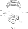
- Figure 15 is a perspective view showing the claw portion 102f provided on the nozzle 102.
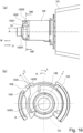
- Part (a) of Figure 16 is a front view showing the claw portion 102f.
- Part (b) of Figure 16 is a sectional view showing a 16B-16B cross section of part (a) of Figure 16 .
- Part (a) of Figure 17 is a front view showing the claw portion 102f.
- Part (b) of Figure 17 is a sectional view showing a 17B-17B cross section of part (a) of Figure 17 .
- the claw portion 102f as a second restricting portion includes, as shown in Figure 15 to part (b) of Figure 16 , an arm portion 102f3, an inclined releasing surface 102f1, and an abutting portion 102f2.
- the claw portion 102f is movable in the radial direction r of the virtual circle VC about the rotational axis A by elastic deformation of the arm portion 102f3.
- the claw portion 102f is movable to a restricting position shown in part (b) of Figure 16 and a non-restricting position which is an inside position than the restricting position with respect to the radial direction r and which is shown in part (b) of Figure 26 .
- the abutting portion 102f2 opposes a restricting portion 103h of the pack-side shutter 103 positioned in the shielding position when the claw portion 102f is positioned in the restricting position as shown in part (b) of Figure 16 , with respect to the circumferential direction about the rotational axis A. At this time, a gap s is provided between the abutting portion 102f2 and the restricting portion 103h. Rotation of the pack-side shutter 103 in the arrow K direction is restricted by abutment of the restricting portion 103h against the abutting portion 102f2.
- a size of the gap s may be set arbitrarily, and a rotation range in which the pack-side shutter 103 is rotatable within a range of the gap s is regarded as the shielding position. That is, the rotation of the pack-side shutter 103 from the shielding position in the arrow K direction is restricted by the claw portion 102f positioned in the restricting position.
- the abutting portion 102f2 is positioned inside the restricting portion 103h of the pack-side shutter 103 with respect to the radial direction r of the virtual circle VC about the rotational axis A. For this reason, the pack-side shutter 103 is capable of being rotated about the rotational axis A without interfering with the abutting portion 102f2.
- the apparatus-side shutter 109 is provided with a restriction releasing rib 109j extending in the axial direction D1.
- the restriction releasing rib 109j is contactable to the inclined releasing surface 102f 1 of the claw portion 102f when the toner pack 100 is mounted to the mounting portion 106.
- the pack-side shutter 103 is provided with an opening 103j, and the opening 103j extends from the end surface (bottom) 103c toward the side surface 103d of the pack-side shutter 103.
- the restriction releasing rib 109j provided in the apparatus-side shutter 109 penetrates through the opening 103j and is capable of contacting the inclined releasing surface 102f1 of the claw portion 102f disposed inside the pack-side shutter 103.
- the inclined releasing surface 102f1 is inclined with respect to the mounting direction M (axial direction D1) so as to extend inward in the radial direction r toward a downstream of the mounting direction M. Further, when the toner pack 100 is mounted to the mounting portion 106, the inclined releasing surface 102f1 converts a direction of a force received from the restriction releasing rib 109j by the claw portion 102f into an inward direction with respect to the radial direction r. By this, the claw portion 102f is moved inward from the restricting position to the non-restricting position in the radial direction r by pressing the inclined releasing surface 102f1 by the restriction releasing rib 109j. In other words, when the toner pack 100 is mounted to the mounting portion 106, the claw portion 102f is moved from the restricting position to non-restricting position by being pressed by the mounting portion 106.
- the pack-side shutter 103 includes a rotation restricting rib 103k
- the nozzle 102 includes a rotation restricting surface 102k as a restricting portion and a first restricting portion opposing the rotation restricting rib 103k with respect to the circumferential direction about the rotational axis A.
- the rotation restricting rib 103k opposes the rotation restricting surface 102k with a small gap therebetween.
- the claw portion 102f is disposed downstream of the rotation restricting surface 102k and the rotation restricting rib 103k with respect to the mounting direction M. This is because the claw portion 102f is disposed in a position where the claw portion 102f is easily pressed by the restriction releasing rib 109j of the apparatus-side shutter 109 when the toner pack 100 is mounted to the mounting portion 106.
- the size of the opening 103j provided in the pack-side shutter 103 can be made small, so that it is possible to not only ensure rigidity of the pack-side shutter 103 but also suppress access to the claw portion 102f by the user.
- arrangement of the claw portion 102f, the rotation restricting surface 102k, and the rotation restricting rib 103k is not limited thereto, but may also be arbitrarily changed.
- the pack-side shutter 103 is provided with three radial direction positioning portions 103f. These radial direction positioning portions 103f project toward an outside than the side surface 103d in the radial direction r. Each of the radial direction positioning portions 103f is disposed on a side upstream of the pack-side shutter 103 with respect to the mounting direction M.
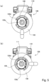
- Part (a) of Figure 18 is a perspective view showing the cap 120 and the toner pack 100.
- Part (b) of Figure 18 is a front view showing a state in which the cap 120 is mounted to the toner pack 100.
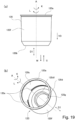
- Part (a) of Figure 19 is a front view showing the cap 120.
- Part (b) of Figure 19 is a perspective view showing the cap 120.
- Part (a) of Figure 20 is a view of the toner pack 100 as viewed in the dismounting direction U.
- Part (b) of Figure 20 is a sectional view showing a 20B-20B cross section of part (a) of Figure 20 in the accommodating container 800.
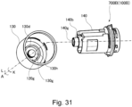
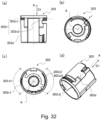
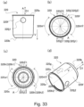
- the cap 120 is mounted to the portion-to-be-mounted 700 as an end portion constituted by the nozzle 102 and the pack-side shutter 103 of the toner pack 100.
- the cap 120 is mounted to the portion-to-be-mounted 700, and thus covers at least a part of the portion-to-be-mounted 700.
- the cap 120 is mounted to the pack-side shutter 103 by being engaged with a screw recessed portion 103g as a second screw portion provided on the side surface (outer peripheral surface) 103d of the pack-side shutter 103.
- the side surface 103d as a second outer surface is disposed outside than the side surface 102c of the nozzle 102 with respect to the radial direction r, and covers at least a part of the side surface 102c with respect to the circumferential direction of the virtual circle VC about the rotational axis A.
- the toner pack 100 and the cap 120 constitute the accommodating container 800 as a container for accommodating the content such as the toner and as a toner container. Further, the accommodating container 800 and the image forming apparatus 1 constitute an image forming system 1000 (see, part (a) of Figure 1 ).
- Part (a) of Figure 29 is a view showing a first screw recessed portion 103g1.
- Part (b) of Figure 29 is a view showing the first screw recessed portion 103g1 and a second screw recessed portion 103g2 in the case where the opening 103a is viewed in front.
- Part (c) of Figure 29 is a view showing the second screw recessed portion 103g2.
- Part (d) of Figure 29 is a bottom view showing the first screw recessed portion 103g1 and the second screw recessed portion 103g2.
- the screw recessed portion includes the first screw recessed portion 103g1 and the second screw recessed portion 103g2 which are groove portions formed in recessed shapes. These first screw recessed portion 103g1 and second screw recessed portion 103g2 are provided on the side surface 103d of the pack-side shutter 103 while avoiding the opening 103a and the portion 103e to which drive is transmitted.
- the first screw recessed portion 103g1 and the second screw recessed portion 103g2 are disposed so as to different in phase by about 180 degrees with respect to the circumferential direction of the virtual circle about the rotational axis A and which oppose each other with respect to radial direction r.
- the first screw recessed portion 103g1 is a recessed groove which opens at an upstream end portion with respect to the arrow K direction and which is closed at a downstream end portion with respect to the arrow K direction. Further, the first screw recessed portion 103g1 includes a cap stopping portion 103gla narrowed in groove width toward the arrow K direction.
- the second screw recessed portion 103g2 is a recessed groove which opens at an upstream end portion with respect to the arrow K direction and which is closed at a downstream end portion with respect to the arrow K direction. Further, the second screw recessed portion 103g2 includes a cap stopping portion 103g2a narrowed in groove width toward a downstream of the arrow K direction. In other words, at least a part of the first screw recessed portion 103g1 and the second screw recessed portion 103g2 is constituted so as to become narrow in groove width toward the arrow K direction.
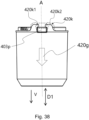
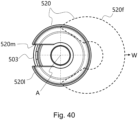
- the cap 120 includes a cap opening 120a, a bottom 120b, an inner peripheral surface 120c, an annular rib 120d, a screw projected portion 120e, and a cap outer surface 120f.
- the annular rib 120d includes an annular rib top surface 120d1 and extends from a surface 120g, opposite from the bottom 120b, toward a downstream, i.e., upward with respect to the dismounting direction U.
- the surface 120g as an opposing surface opposes the end surface 103c of the pack-side shutter 103 and the projected portion 102b of the nozzle 102.
- the screw projected portion 120e as a first screw portion is provided on the inner peripheral surface 120c as an inner surface extending along the rotational axis A and projects from the inner peripheral surface 120c toward the inside in the radial direction r.
- the screw projected portion 120e is capable of engaging with the screw recessed portion 103g of the pack-side shutter 103 by rotating the cap 120 in the arrow K direction.
- the screw projected portion 120e is engaged with the screw recessed portion 103g, so that the cap 120 is mounted to the pack-side shutter 103.
- the inner peripheral surface 120c of the cap 120 is constituted so as to surround at least a part of the side surface 103d of the pack-side shutter 103, and surrounds entirety of the side surface 103d in this embodiment.
- Part (a) of Figure 30 is a front view showing the cap 120.
- Part (b) of Figure 30 is a sectional view showing a 30B-30B cross section of part (a) of Figure 30 .
- Part (c) of Figure 30 is a sectional view showing a 30C-30C cross section of part (b) of Figure 30 .
- Part (d) of Figure 30 is a sectional view showing a 30D-30D cross section of part (c) of Figure 30 .
- the screw projected portion 120e includes, as shown in parts (a) to (d) of Figure 30 , a first screw projected portion 120e1, a second screw projected portion 120e2, a third screw projected portion 120e3, and a fourth screw projected portion 120e4 each formed in a projected shape from the inner peripheral surface 120c.
- These first screw projected portion 120e1, second screw projected portion 120e2, third screw projected portion 120e3, and fourth screw projected portion 120e4 are arranged and disposed in the circumferential direction of the virtual circle about the rotational axis A with a gap from each other.
- the first screw projected portion 120e1 and the third screw projected portion 120e3 are disposed so as to be different in phase by about 180 degrees with respect to the circumferential direction of the virtual circle about the rotational axis A and oppose each other with respect to the radial direction r.
- the second screw projected portion 120e2 and the fourth screw projected portion 120e4 are disposed so as to be different in phase by about 180 degrees with respect to the circumferential direction of the virtual circle about the rotational axis A and oppose each other with respect to the radial direction r. That is, the first screw projected portion 120e1, the second screw projected portion 120e2, the third screw projected portion 120e3, and the fourth screw projected portion 120e4 are disposed so as to be different in phase by about 90 degrees with respect to the circumferential direction.
- a gap S1 is provided between the first screw projected portion 120e1 and the second screw projected portion 120e2, and a gap S2 is provided between the second screw projected portion 120e2 and the third screw projected portion 120e3.
- a gap S3 is provided between the third screw projected portion 120e3 and the fourth screw projected portion 120e4, and a gap S4 is provided between the fourth screw projected portion 120e4 and the first screw projected portion 120e1. That is, with respect to the circumferential direction, the first screw projected portion 120e1 as a first portion and the second screw projected portion 120e2 as a second portion are disposed adjacently with the gap S2.
- the first screw projected portion 120e1, the second screw projected portion 120e2, and the gap S 1 are positioned on a circumference of a circle about the rotational axis A as viewed in the rotational axis A. Further, a length of a portion overlapping with the gap S 1 of the circumference is longer than a length of a portion overlapping with the first screw projected portion 120e1 and the second screw projected portion 120e2 of the circumference.
- a length L5 of the gap S 1 is longer than a length L1 of the first screw projected portion 120e1 and a length L2 of the second screw projected portion 120e2.
- a length L6 of the gap S2 is longer than the length L2 of the second screw projected portion 120e2 and a length L3 of the third screw projected portion 120e3.
- a length L7 of the gap S3 is longer than the length L3 of the third screw projected portion 120e3 and a length L4 of the fourth screw projected portion 120e4.
- a length L8 of the gap S4 is longer than the length L4 of the fourth screw projected portion 120e4 and the length L1 of the first screw projected portion 120e1.
- first screw projected portion 120e1, the second screw projected portion 120e2, the third screw projected portion 120e3, and the fourth screw projected portion 120e4 are formed in an arcuate shape as viewed in a direction (axial direction D1) of the rotational axis A.
- Circumferential angles ⁇ 1, ⁇ 2, ⁇ 3, and ⁇ 4 of the first screw projected portion 120e1, the second screw projected portion 120e2, the third screw projected portion 120e3, and the fourth screw projected portion 120e4, respectively, are 90 degrees or less.
- each of the circumferential angles ⁇ 1, ⁇ 2, ⁇ 3, and ⁇ 4 is set equally.
- the screw projected portion 120e of the cap 120 is thus formed, so that when the cap 120 is dismounted from the toner pack 100, the cap 120 is rotated in the arrow L direction by the circumferential angle ⁇ 1 ( ⁇ 2, ⁇ 3, ⁇ 4).
- the circumferential angle ⁇ 1 ( ⁇ 2, ⁇ 3, ⁇ 4) is smaller than 90 degrees and is smaller than 45 degrees in this embodiment. For this reason, the cap 120 can be easily dismounted only by rotating the cap 120 relative to the toner pack 100 by a relatively small angle.
- the pack-side shutter 103 of the toner pack 100 is covered with the cap 120.
- the first screw recessed portion 103g1 and the second screw recessed portion 103g2 which are formed on the pack-side shutter 103 enter the gaps S 1 and S3 or the gaps S2 and S4.
- the cap 120 is rotated in the arrow K direction, the first screw projected portion 120e1 and the third screw projected portion 120e3 of the cap 120 or the second screw projected portion 120e2 and the fourth screw projected portion 120e4 of the cap 120 engage with the first screw recessed portion 103g1 and the second screw recessed portion 103g2.
- the first screw recessed portion 103g1 and the second screw recessed portion 103g2 are provided with the cap stopping portions 103gla and 103g2a, and therefore, with rotation of the cap 120 in the arrow K direction, a sliding resistance between the screw projected portion 120e and the screw recessed portion 103g becomes large. For this reason, the user is capable of easily recognizing a fastening degree of the cap 120.
- the accommodating container 800 including the toner pack 100 and the cap 120 is directed so that the rotational axis A becomes parallel to the vertical direction VD and so that the nozzle 102 is positioned below the pouch 101
- Such an attitude of the accommodating container 800 is similar to an attitude when the toner pack 100 is mounted to the mounting portion 106.
- the annular rib 120d extends upward from the surface 120g.
- the bottom 120b is a surface which is an end surface of the cap 120 with respect to the mounting direction M and which is perpendicular to the rotational axis A, and constitutes the bottom of the accommodating container 800 in the state in which the cap 120 is mounted to the toner pack 100.
- the bottom 120b extends in the horizontal direction when the accommodating container 800 is in the attitude shown in part (b) of Figure 18 and part (a) of Figure 19 .
- the accommodating container 800 is constituted so as to be capable of being self-standing by contact of the bottom 120b as a surface with an installation surface.
- the cap 120 is mounted on the pack-side shutter 103 of the portion-to-be-mounted 700 so as to cover the portion-to-be-mounted 700 of the toner pack 100.
- the annular rib 120d of the cap 120 is provided outside the projected portion 102b of the nozzle 102 with respect to the radial direction r and is provided so as to surround the projected portion 102b.
- the annular rib 120d as a second projected portion is disposed so as not to overlap with the projected portion 102b as viewed in the vertical direction (the dismounting direction U or the mounting direction M).
- a gap m as a distance is provided between the projected portion end surface 102b2 as an end of the projected portion 102b and the surface 120g.
- a gap n as a distance is provided between the annular rib top surface 120d1 as an end of the annular rib 120d and the end surface 103c of the pack-side shutter 103.
- magnitudes of the gaps m and n satisfy a relationship of m > n. For this reason, even when the cap 120 is externally shocked during transportation or the like, before the projected portion end surface 102b2 contacts the surface 120g, the annular rib top surface 120d1 contacts the end surface 103c of the pack-side shutter 103. That is, it is possible to reduce a degree of collision of the projected portion end surface 102b2 with the surface 120g.
- the projected portion end surface 102b2 is, as described later, abutted against a pack contact surface 109g (see, part (a) of Figure 6 ) of the apparatus-side shutter 109 when the toner pack 100 is mounted to the mounting portion 106, and performs positioning of the toner pack 100 with respect to the mounting direction M. Accordingly, the projected portion end surface 102b2 is protected by the cap 120, so that positioning accuracy of the toner pack 100 relative to the mounting portion 106 with respect to the mounting direction M can be improved.
- the cap opening 120a is disposed downstream of the portion-to-be-positioned 102d and the portion 103e to which drive is transmitted, with respect to the dismounting direction U. That is, the portion-to-be-positioned 102d and the portion 103e to which drive is transmitted are covered and protected by the cap outer surface 120f of the cap 120.
- the portion-to-be-positioned 102d is used for positioning the nozzle 102 relative to the first frame 107 (the main apparatus base portion 2) with respect to the rotational direction about the rotational axis A.
- the portion 103e to which drive is transmitted is used in a rotational operation of the pack-side shutter 103 by the operating lever 108 by being engaged with the drive transmitting portion 108a of the operating lever 108.
- portions of the portion-to-be-mounted 700 of the toner pack 100 other than the recessed screw recessed portion 103g are spaced from the inner peripheral surface 120c of the cap 120. By this, the respective portions of the portion-to-be-mounted 700 are protected from the shock by the cap 120.
- the cap 120 in the state in which the cap 120 is mounted to the portion-to-be-mounted 700 of the toner pack 100, even when the toner leaks out through the discharging opening 102a of the nozzle 102, the cap 120 becomes a saucer for the leaked toner. For this reason, the user is capable of reducing a degree of deposition of the toner on user's hand(s) or the like without touching the leaked toner.
- the content accommodated in the toner pack 100 is a liquid
- the toner leaked out onto the cap 120 is dried on the cap 120 with a lapse of time. By this, it is possible to reduce a degree of deposition of the content on the user's hand(s) or the like.
- Part (a) of Figure 21 is a perspective view showing the toner pack 100 to which the cap 120 is mounted.
- Part (b) of Figure 21 is a perspective view showing a state in which the cap 120 is dismounted from the toner pack 100.
- Part (a) and (b) of Figure 22 are perspective views each showing a state in which the toner pack 100 is being mounted onto the mounting portion 106 as viewed in a different angle.
- Part (a) of Figure 23 is a sectional view showing a state in which the toner pack 100 is being mounted onto the mounting portion 106.
- Part (b) of Figure 23 is a sectional view showing a state in which mounting of the toner pack 100 to the mounting portion 106 is completed.
- Part (a) of Figure 24 is a sectional view showing a 24A-24A cross section of part (a) of Figure 23 .
- Part (b) of Figure 24 is a sectional view showing a 24B-24B cross section of part (a) of Figure 23 .
- Part (a) of Figure 25 is a sectional view showing a 25A-25A cross section of part (b) of Figure 23 .
- Part (b) of Figure 25 is a sectional view showing a 25B-25B cross section of part (b) of Figure 25 .
- Part (a) of Figure 26 is a perspective view showing a state when the toner pack 100 is mounted to the apparatus-side shutter 109.
- Part (b) of Figure 26 is a sectional view showing the 17B-17B cross section of part (a) of Figure 17 in a state in which mounting of the toner pack 100 to the mounting portion 106 is completed.
- cut surfaces of the pack-side shutter 103 and the cover 110 are hatched, and in part (b) of Figure 26 , a cut surface of the nozzle 102 is hatched.
- a movement direction (arrow L direction) of the cap 120 for releasing engagement of the cap 120 with the pack-side shutter 103 is the same as a movement direction (arrow L direction) of the pack-side shutter 103 when the pack-side shutter 103 is moved from the open position to the shielding position (closed position).
- the cap 120 is dismounted from the portion-to-be-mounted 700 of the toner pack 100 by released in engagement between the screw recessed portion 103g and the screw projected portion 120e (see, part (b) of Figure 19 ).
- the user dismounts the cap 120 from the toner pack 100, and exposed the portion 103e to which drive is transmitted, the projected portion 102b, and the portion-to-be-positioned 102d of the portion-to-be-mounted 700 (see, parts (a) and (b) of Figure 11 ).
- the portion-to-be-mounted 700 of the toner pack 100 is mountable to the mounting portion 106 of the image forming apparatus 1 in a state in which the cap 120 is dismounted.
- the cap 120 can be mounted again to the portion-to-be-mounted 700 of the toner pack 100.
- the user mounts, as shown in parts (a) and (b) of Figure 22 , the toner pack 100 onto the mounting portion 106 in a state in which the apparatus-side shutter 109 is in the shielding position, by moving the toner pack 100, in a state in which the pack-side shutter 103 is in the shielding position, in the mounting direction M.
- the user positionally aligns the recessed portion 102e of the nozzle 102 and the opening 103a of the pack-side shutter 103 with the positioning portion 107a of the first frame 107.
- the user also aligns a position of the portion 103e, to which drive is transmitted, of the pack-side shutter 103 with a position of the drive transmitting portion 108a of the operating lever 108.
- the user After such positional alignment of the toner pack 100 with the mounting portion 106, the user gradually mounts the toner pack 100 onto the mounting portion 106 by moving the toner pack 100 in the mounting direction M. Then, as shown in part (b) of Figure 23 , with the inner peripheral surface 102b1 of the projected portion 102b of the nozzle 102, a small-diameter portion 109d2 of the center boss 109d of the apparatus-side shutter is engaged. By this, a position of the nozzle 102 relative to the apparatus-side shutter 109 with respect to the radial direction r is determined.
- the drive transmitting portion 108a of the operating lever 108 and the portion 103e, to which drive is transmitted, of the pack-side shutter 103 engage with each other, as shown in part (a) of Figure 24 .
- the side surfaces 110f and 110g of the cover 110 come close to or engage with the surfaces 102e1 and 102e2, respectively, forming the recessed portion 102e of the nozzle 102.
- the portion 103e, to which drive is transmitted, of the pack-side shutter 103 engages with the portion 109e, to which drive is transmitted, of the apparatus-side shutter 109 and the drive transmitting portion 108a of the operating lever 108.
- the rotational axis A of the pack-side shutter 103 and the rotational axis B of the apparatus-side shutter 109 are substantially coaxial with each other.
- the surfaces 102e1 and 102e2 of the recessed portion 102e of the nozzle 102 engage with the side surfaces 110f and 110g, respectively, of the cover 110, so that the nozzle 102 of the toner pack 100 does not rotate relative to the main body base portion 2 including the cover 110.
- the recessed portion 102e engages with the cover 110 of the image forming apparatus 1, and thus restricts rotation of the nozzle 102 relative to the image forming apparatus 1.
- the operating lever 108, the pack-side shutter 103, and the apparatus-side shutter 109 are rotatable substantially integrally relative to the main body base portion 2 and the nozzle 102 with the rotational axis B as a center.
- the drive transmitting portion 108a of the operating lever 108 presses the surface 103b1 or 103b2 of the pack-side shutter 103, so that the pack-side shutter 103 is rotated. Thereafter, the surface 103b1 or 103b2 constituting the portion 103e to which drive is transmitted of the pack-side shutter 103 presses the portion 109e, to which drive is transmitted of the apparatus-side shutter 109, so that the apparatus-side shutter 109 is rotated.
- the projected portion end surface 102b2 of the projected portion 102b of the nozzle 102 abuts against the pack contact surface 109g, so that a position of the toner pack 100 with respect to the mounting direction M is determined.
- a constitution in which the outer peripheral surface of the projected portion 102b is engaged with the cylindrical portion 110j of the cover 110 may be employed.
- the portion-to-be-positioned 102d provided on the nozzle 102 engages with the positioning portion 107a of the first frame 107.
- rotation of the nozzle 102 of the toner pack 100 relative to the first frame 107 (main assembly base portion 2) is restricted.
- the claw portion 102f provided on the nozzle 102 is moved from the restricting position to the non-restricting position (position shown in part (b) of Figure 26 ). Specifically, the claw portion 102f is moved inward from the restricting position toward the non-restricting position in the radial direction r by pressing of the inclined releasing surface 102f1 by the restriction releasing rib 109j. By this, rotation restriction of the pack-side shutter 103 in the arrow K direction is released.
- Parts (a) of Figure 27 is a perspective view showing the operating lever 108 positioned in the closed position and the toner pack 100.
- Part (b) of Figure 27 is a perspective view showing the operating lever 108 positioned in the open position and the toner pack 100.
- Part (a) of Figure 28 is a sectional view showing the toner pack 100 and the mounting portion 106 when both the apparatus-side shutter 109 and the pack-side shutter 103 are positioned in the shielding positions.
- Part (b) of Figure 28 is a sectional view showing the toner pack 100 and the mounting portion 106 when both the apparatus-side shutter 109 and the pack-side shutter 103 are positioned in the open positions.
- the operating lever 108, the pack-side shutter 103, and the apparatus-side shutter 109 are integrally rotatable about the rotational axis B relative to the main assembly base portion 2 and the nozzle 102.
- the discharging opening 102a is shielded by the pack-side shutter 103, the pack-side seal 105, and the apparatus-side shutter 109.
- the toner in the pouch 101 is constituted so that the toner cannot reach the apparatus-side opening 117a of the second frame 117.
- the drive transmitting portion 108a of the operating lever 108 presses the surface 103b1 of the pack-side shutter 103.
- the pack-side shutter 103 is rotated together with the operating lever 108 from the shielding position to the open position.
- the pack-side shutter 103 is rotated from the shielding position to the open position in interrelation with the rotation of the operating lever 108 through engagement between the drive transmitting portion 108a and the surface 103b1 as an engaging portion and a first engaging portion.
- the surface 103b of the pack-side shutter 103 rotated from the shielding position to the open position presses, the portion 109e, to which the drive is transmitted, of the apparatus-side shutter 109.
- the apparatus-side shutter 109 is rotated together with the pack-side shutter 103 from the shielding position to the open position.
- the apparatus-side shutter 109 is rotated in interrelation with the rotation of the operating lever 108 through engagement between the surface 103b2 as a second engaging portion, and the portion 109e to which drive is transmitted.
- the discharging opening 102a of the nozzle 102 is opened by movement of the pack-side shutter 103, the pack-side seal 105, and the apparatus-side shutter 109. That is, the pouch 101 of the toner pack 100 and the accommodating portion 36 communicate with each other by way of the discharging opening 102a, the receiving opening 109a, and the apparatus-side opening 117a.
- the toner in the pouch 101 is supplied together with the air to the accommodating portion 36 of the developing container 32 by way of the discharging opening 102a, the receiving opening 109a, and the apparatus-side opening 117a by compression of the pouch 101 by the user.
- the user rotates the operating lever 108 from the open position to the closed position when the supply of the toner from the toner pack 100 to the developing container 32 is completed.
- the drive transmitting portion 108a of the operating lever 108 presses the surface 103b2 of the pack-side shutter 103.
- the pack-side shutter 103 is rotated together with the operating lever 108 from the open position to the shielding position.
- the surface 103b1 of the pack-side shutter 103 rotated from the open position to the shielding position presses, the portion 109e, to which the drive is transmitted, of the apparatus-side shutter 109.
- the apparatus-side shutter 109 is rotated together with the pack-side shutter 103 from the open position to the shielding position.
- the surface 103b2 constitutes the engaging portion
- the surface 103b1 constitutes the second engaging portion.
- the user pulls out the toner pack 100 from the mounting portion 106, so that a supplying operation of the toner is completed.
- the user may mount the cap 120 or may separately dispose of the cap 120 and the toner pack 100.
- the accommodating container 800 mountable to the image forming apparatus 1.
- the cap 120 is mounted to the portion-to-be-mounted 700 of the toner pack 100, so that the portion-to-be-mounted 700 can be protected.
- the cap 120 is capable of protecting the portion 103e to which drive is transmitted, of the portion-to-be-mounted 700, the projected portion 102b, and the portion-to-be-positioned 102d.
- the portion 103e to which drive is transmitted, the projected portion 102b, and the portion-to-be-positioned 102d are used for positioning of the toner pack 100 (the nozzle 102) relative to the mounting portion 106 and for the rotational operation of the pack-side shutter 103 by the operating lever 108. For this reason, the portion 103e to which drive is transmitted, the projected portion 102b, and the portion-to-be-positioned 102d are prevented from being broken by an external shock (impact), or the like before the toner supply, so that the toner supply from the toner pack 100 toward the developing container 32 can be appropriately performed.
- a cap is configured so as to be mountable to a nozzle.
- constituent elements similar to those in the first embodiment will be omitted from illustration or will be described by adding the same reference numerals or symbols to the figures.
- Figure 31 is an exploded perspective view showing a cap 130 and a nozzle 140.
- a portion-to-be-mounted 700B of a toner pack 100B in this embodiment includes the nozzle 140 and an unshown pack-side shutter as shown in Figure 31 .
- the pack-side shutter in this embodiment is one prepared by omitting the screw recessed portion 103g from the pack-side shutter 103 in the first embodiment, and therefore will be omitted from description.
- the nozzle 140 includes a projected portion 140b, and an inner peripheral surface of the projected portion 140b is provided with a screw recessed portion 140g.
- the cap 130 includes a boss portion 130h projected from a surface 120g along a rotational axis A. At a side surface of the boss portion 130h, a screw projected portion 130g engageable with a screw recessed portion 140g is provided.
- the nozzle 140 has a constitution similar to the constitution of the nozzle 102 in the first embodiment except for the projected portion 140b.
- the cap 130 has a constitution similar to the constitution of the cap 120 in the first embodiment except for the boss portion 130h.
- the portion-to-be-mounted 700 of the toner pack 100B by mounting the cap 130 to the portion-to-be-mounted 700 of the toner pack 100B, the portion-to-be-mounted 700 can be protected.
- Part (a) of Figure 32 is a front view of a pack-side shutter 303.
- Part (b) of Figure 32 is a plan view of the pack-side shutter 303.
- Part (c) of Figure 32 is a bottom view of the pack-side shutter 303.
- Part (d) of Figure 32 is a perspective view of the pack-side shutter 303.
- Part (a) of Figure 33 is a front view of a cap 320.
- Part (b) of Figure 33 is a plan view of the cap 320.
- Part (c) of Figure 33 is a bottom view of the cap 320.
- Part (d) of Figure 34 is a perspective view of the cap 320.
- Part (a) of Figure 34 is a view of an accommodating container 800 as viewed along a rotational axis A from a cap 320 side.
- Part (b) of Figure 34 is a sectional view showing a 34B-34B cross section of part (a) of Figure 34 .
- Figure 35 is a bottom view showing the cap 320 and the pack-side shutter 303 when the cap 320 is dismounted from the pack-side shutter 303.
- the pack-side shutter 303 in this embodiment will be described. As shown in parts (a) to (d) of Figure 32 , the pack-side shutter 303 includes a recessed portion 303n (portion-to-be-engaged) 303n.
- the recessed portion 303n is a groove portion provided along the circumferential direction about the rotational axis A at a side surface (outer peripheral surface) 303d of the pack-side shutter 303.
- the recessed portion 303n includes a first recessed portion 303n1 (first portion-to-be-engaged) and a second recessed portion 303n2 (second portion-to-be-engaged).
- the first recessed portion 303n1 and the second recessed portion 303n2 are provided in a region 303 ⁇ 1 and a region 303 ⁇ 2 of the side surface 303d, respectively, which are on opposite sides to each other with respect to the rotational axis A in a direction perpendicular to the rotational axis A as viewed in a direction of the rotational axis A. Further, the first recessed portion 303n1 and the second recessed portion 303n2 are provided at an end portion of the side surface 303d on a side close to the pouch 101 in the direction of the rotational axis A.
- the cap 320 in this embodiment will be described.
- the cap 320 is constituted so as to be dismounted from the pack-side shutter 303 by being linearly moved relative to the pack-side shutter 303 in a direction which is an axial direction D1 (first direction, the direction of the rotational axis A) and in which the cap 320 is separated from the pouch 101. That is, a dismounting direction V of the cap is a direction along the direction (axial direction D1) of the rotational axis A.
- the cap 320 is, as shown in parts (a) to (d) of Figure 33 , a cylindrical member about the rotational axis A and includes a projected portion 320h (engaging portion) and a potion-to-be-urged (pressed) 320j.
- the projected portion 320h is provided on an inner peripheral surface 320c about the rotational axis A.
- the projected portion 320h extends along a circumferential direction about the rotational axis A of the inner peripheral surface 320c and projected from the inner peripheral surface 320c toward an inside in the radial direction r with the rotational axis A as a center.
- the projected portion 320h includes a first projected portion 320h1 (first engaging portion) and a second projected portion 320h2 (second engaging portion).
- the first projected portion 320h1 and the second projected portion 320h2 are provided in a region 320 ⁇ 1 and a region 320 ⁇ 2 of the inner peripheral surface 302c, respectively, which are on opposite sides to each other with respect to the rotational axis A in a direction perpendicular to the rotational axis A as viewed in the direction of the rotational axis A. Further, the first projected portion 320h1 and the second projected portion 320h2 are provided at an end portion of the cap 320 on a side (side where there is an opening of the cap) close to the pouch 101 in the direction of the rotational axis A.
- the first projected portion 320h1 and the second projected portion 320h2 may preferably be provided in positions closer to an opening 320a of the cap 320 than to a bottom 320b of the cap 320.
- the potion-to-be-urged 320j is provided on an outer peripheral surface 320f of the cap 320 about the rotational axis A, and has a projected shape projected from the outer peripheral surface 320f in the radial direction r.
- the potion-to-be-urged 320j includes a first potion-to-be-urged 320j 1 and a second potion-to-be-urged 320j2.
- the first potion-to-be-urged 320j1 and the second potion-to-be-urged 320j2 are provided in a region 320 ⁇ 1 and a region 320 ⁇ 2 of the outer peripheral surface 320f, respectively, which are on opposite sides to each other with respect to the rotational axis A in a direction perpendicular to the rotational axis A as viewed in the direction of the rotational axis A.
- each of the region 320 ⁇ 1 and the region 320 ⁇ 2 of the outer peripheral surface 320f is provided between the region 320 ⁇ 1 and the region 320 ⁇ 2 of the inner peripheral surface with respect to the circumferential direction about the rotational axis A.
- each of the first potion-to-be-urged 320j 1 and the second potion-to-be-urged 320j2 is provided between the first projected portion 320h1 and the second projected portion 320h2 with respect to the circumferential direction about the rotational axis A.
- the potion-to-be-urged 320j may also be a recessed-shape portion provided on the outer peripheral surface 320f, a seal stuck to the outer peripheral surface 320f, or a pattern or an illustration drawn on the outer peripheral surface 320f.
- the outer peripheral surface 320f of the cap 320 is provided with an arrow-shaped projected portion 320g directed in the dismounting direction V.
- the arrow-shaped projected portion 320g is provided between the first potion-to-be-urged 320j 1 and the second potion-to-be-urged 320g2 with respect to the circumferential direction.
- This arrow-shaped projected portion 320g may be constituted by a projected-shape portion or a recessed-shape portion, but may also be free from unevenness or may be a seal or the like. The user visually recognize the arrow-shaped projected portion 320g, and thus is capable of recognizing the dismounting direction of the cap 320.
- Part (a) of Figure 34 is a view of an accommodating container 800 in a state in which the cap 320 is mounted to the pack-side shutter 303, as viewed from a bottom side.
- Part (b) of Figure 34 includes a sectional view showing a 34B-34B cross section of part (a) of Figure 34 and a partially enlarged view thereof.
- the first projected portion 320h1 and the second projected portion 320h2 of the cap 320 are engaged with the first recessed portion 303n1 and the second recessed portion 303n2 of the pack-side shutter 303, respectively.
- the first projected portion 320h1 and the second projected portion 320h2 thereof are engaged with the first recessed portion 303n1 and the second recessed portion 303n2 of the pack-side shutter 303, respectively, so that movement of the cap 320 relative to the pack-side shutter 303 in the dismounting direction V is restricted.
- Each of the first projected portion 320h1 and the second projected portion 320h2 is disposed so as to be deviated in phase from the first potion-to-be-urged 320j 1 and the second potion-to-be-urged 320j2 by about 90 degrees in the circumferential direction.
- the cap 320 is dismounted from the pack-side shutter 303 (toner pack 100)
- the user urges (presses) the potion-to-be-urged 320j of the cap 320 toward an inside with respect to the radial direction r.
- the cap is deformed in an elliptical shape indicated by a broken line, so that the first projected portion 320h1 and the second projected portion 302h2 of the cap 320 are separated from the first recessed portion 303n1 and the second recessed portion 303n2 of the pack-side shutter 303, respectively, in the radial direction r.
- engagement between the first projected portion 320h1 and the first recessed portion 303n1 and engagement between the second projected portion 302h2 and the second recessed portion 303n2 are released, so that the cap 320 can be dismounted from the pack-side shutter 303.
- the first potion-to-be-urged 320j 1 and the second potion-to-be-urged 320j2 are urged toward the rotational axis A, the first projected portion 320h1 is separated from the first recessed portion 303n1 and thus the engagement of these portions is released, and the second projected portion 320h2 is separated from the second recessed portion 303n2 and thus the engagement of these portions is released.
- the user urges the first potion-to-be-urged 320j 1 and the second potion-to-be-urged 320j2 with his/her thump and forefinger, so that the user is capable of easily dismounting the cap 320 from the toner pack 100 only by an operation with his/her one hand.
- the potion-to-be-urged of the pack-side shutter 303 was the recessed portion, and the engaging portion of the cap 320 was the projected portion, but the present invention is not limited thereto.
- the potion-to-be-urged of the pack-side shutter 303 may be a projected portion, and the engaging portion of the cap 320 may be a recessed portion. That is, it may only be required that either one of the engaging portion of the cap 320 and the potion-to-be-urged of the pack-side shutter 303 in provided with the projected portion, and the other is provided with the recessed portion.
- Part (a) of Figure 36 is a front view showing a pack-side shutter 403.
- Part (b) of Figure 36 is a perspective view showing the pack-side shutter 403.
- Part (a) of Figure 37 is a front view showing a cap 420.
- Part (b) of Figure 37 is a perspective view showing the cap 420.
- Figure 38 is a front view showing the cap 420 and the pack-side shutter 403 when the cap 420 is dismounted from the pack-side shutter 403.
- the pack-side shutter 403 includes a projection 403p as a portion-to-be-engaged as shown in parts (a) and (b) of Figure 36 .
- the projection 403p has a projected shape projecting from a side surface 403d of the pack-side shutter 403 with the rotational axis A as a center toward the outside in the radial direction about the rotational axis A.
- the cap 420 includes a biting portion 420k as an engaging portion.
- the biting portion 420k is provided so as to project from an opening 420a of the cap 420 in a direction opposite to the dismounting direction V.
- the biting portion 420k includes a first engaging arm 420k1 and a second engaging arm 420k2.
- the second engaging arm 420k2 is disposed in a position different from a position of the first engaging arm 420k1 with respect to the circumferential direction about the rotational axis A of the cap 420.
- the first engaging arm 420k1 and the second engaging arm 420k2 are constituted so as to be elastically deformed in a direction in which these arms are separated from each other in the circumferential direction.
- the projection 403p of the pack-side shutter 403 is bitten (caught) between the first engaging arm 420k1 and the second engaging arm 420k2 of the cap 420.
- the projection 403p of the pack-side shutter 403 is sandwiched between the first engaging arm 420k1 and the second engaging arm 420k2 of the cap 420.
- the cap 420 when the cap 420 is intended to be moved in the dismounting direction V relative to the pack-side shutter 403, the first engaging arm 420k1 and the second engaging arm 420k2 of the biting portion 420k are elastically deformed in a direction in which these portions are separated from each other by receiving a force from the projection 403p.
- the first engaging arm 120k1 and the second engaging arm 120k2 get over the projection 403p of the pack-side shutter 403, so that the cap 420 is dismounted from the pack-side shutter 403.
- the cap 420 is constituted so as to be linearly moved in the dismounting direction V relatively to the pack-side shutter 403, whereby engagement of the cap 420 with the pack-side shutter 403 is released.
- the biting portion 420k of the projection 403p is constituted so as to be capable of being visually recognized by the user, so that the user can easily dismounting the cap 420 from the pack-side shutter 403.
- the outer peripheral surface 420f of the cap 420 is provided with an arrow-shaped projected portion 420g directed in the dismounting direction V.
- the arrow-shaped projected portion 420g is provided between the first engaging arm 120k1 and the second engaging arm 120k2 with respect to the circumferential direction.
- This arrow-shaped projected portion 420g may be constituted by a projected-shape portion or a recessed-shape portion, but may also be free from unevenness or may be a seal or the like. The user visually recognize the arrow-shaped projected portion 420g, and thus is capable of recognizing the dismounting direction of the cap 420.
- Part (a) of Figure 39 is a front view of a cap 520 according to this embodiment.
- Part (b) of Figure 39 is a respective view of the cap 520.
- Figure 40 is a plan view showing the cap 520 and the pack-side shutter 503 when the cap 520 is dismounted from the pack-side shutter 503.
- the cap 520 includes a slit 520m as shown in parts (a) and (b) of Figure 39 .
- the slit 520m is provided in a side wall 5201 which is the side wall 5201 of the cap 520 with the rotational axis A (center axis, first direction) as a center and which extends in the direction of the rotational axis A.
- the slit 520m penetrates through the side wall 5201 from an inside toward an outside of the side wall 5201 in the radial direction r with the rotational axis A as a center, and extends from an opening 520a to a bottom 520b in the direction of the rotational axis A.
- a dismounting direction W of the cap 520 is a direction crossing (direction perpendicular to) the rotational axis A as shown in Figure 40 .
- the side wall 5201 is elastically deformed, so that a width of the slit 520m is expanded as indicated by a broken line of Figure 40 .
- the slit 520m gets over the pack-side shutter 503, so that the user is capable of dismounting the cap 520 from the pack-side shutter 503.
- the slit 520m is a portion where when the cap 520 is dismounted, the pack-side shutter 503 and the nozzle 102 passes from an inside toward the outside of the cap 520.
- the slit 520m is provided in the side wall 5201 of the cap 520, so that the user easily recognizes the dismounting direction W and thus is capable of easily dismounting the cap 520.
- an arrow-shaped projected portion 520g directed in the dismounting direction W is provided on the bottom of the cap 520.
- This arrow-shaped projected portion 520g may be constituted by a projected-shape portion or a recessed-shape portion, but may also be free from unevenness or may be a seal or the like. Further, the arrow-shaped projected portion may also be provided on an outer peripheral surface 520f of the cap 520, not on the bottom 520b.
- the cap may also be mounted to any member of the toner pack without limiting the portion-to-be-mounted to the nozzle or the pack-side shutter.
- the toner was accommodated in the pouch 101 of the toner pack 100, but the present invention is not limited thereto.
- ink may be used, and powder or a liquid is capable of being accommodated in the pouch 101.
- the powder accommodatable in the pouch 101 is not limited to the toner.
- the toner pack 100 may be mounted to an image forming apparatus of an inkjet type.
- the pack-side shutter 103 and the apparatus-side shutter 109 were constituted so as to be rotatable about the rotational axes A and B between the shielding position and the open position, but the present invention is not limited thereto.
- the pack-side shutter 103 and the apparatus-side shutter 109 may be constituted so as to be movable between the shielding position and the open position by being linearly moved parallel to the mounting direction M.
- the pack-side shutter 103 was constituted so as to open the discharging opening 102a of the nozzle 102 only in the open position, but the present invention is not limited thereto.
- the pack-side shutter 103 may be a rotatable member which opens the discharging opening 102a of the nozzle 102 irrespective of a rotation position.
- the discharging opening 102a of the nozzle 102 may employ a constitution in which the discharging opening 102a is closed by a seal when the toner pack 100 is not yet mounted to the mounting portion 106 and then the seal is removed by a mounting operation of the toner pack 100 onto the mounting portion 106 or after the toner pack 100 is mounted.
- a constitution in which the pack-side shutter 103 of the toner pack 100 is omitted may be employed.
- the pack-side shutter 103 was provided with the screw recessed portion 103g which is a female screw, and the cap 120 was provided with the screw projected portion 120e which is a male screw, but the present invention is not limited thereto.
- the pack-side shutter 103 may be provided with the male screw, and the cap 120 may be provided with the female screw.
- the nozzle 140 may be provided with the male screw, and the cap 130 may be provided with the female screw. That is, it may only be required that either one of the cap 120 and the pack-side shutter 103 is provided with the projected portion, and the other of the cap 120 and the pack-side shutter 103 is provided with the recessed portion engageable with the projected portion.
- disclosure of this embodiment includes the following constitution examples and method examples.
- a container according to Constitution 2 wherein in a case that the container is directed so that the rotational axis is parallel to a vertical direction and so that the discharging portion is below the accommodating portion,
- a container according to Constitution 3 wherein a distance between an end of the second projecting portion of the cap and the shutter end surface is shorter than a distance between an end of the first projecting portion of the discharging portion and the opposing surface of the cap.
- a container according to Constitution 3 or 4 wherein the second projecting portion is provided outside the first projecting portion of the discharging portion with respect to a radial direction of a virtual circle about the rotational axis and is provided so as to surround the first projecting portion.
- a container according to Constitution 9 wherein the shutter is rotatable about the rotational axis in a first rotational direction from the shielding position toward the open position and in a second rotational direction opposite to the first rotational direction,
- a container according to Constitution 10 wherein the discharging portion includes a second restricting portion movable to a restricting position where the second restricting portion restricts rotation of the shutter, positioned in the shielding position, in the first rotational direction and to a non-restricting position where the second restricting portion does not restrict the rotation of the shutter.
- a container according to Constitution 11 wherein the end portion of the container is detachably mountable to a mounting portion of the image forming apparatus in a state in which the cap is dismounted, and wherein the second restricting portion is moved from the restricting position to the non-restricting position by being urged by the mounting portion when the container is mounted to the mounting portion of the image forming apparatus.
- a container according to Constitution 14 wherein the first portion and the second portion are formed in an arcuate shape as viewed in the direction of the rotational axis, and a circumferential angle of each of the first portion and the second portion is 90 degrees or less.
- a toner container comprising:
- a toner container according to any one of Constitutions 23 to 25, wherein the cap is configured so that the engagement of the cap with the shutter is released by being rotated about a rotational axis, extending in the first direction, relative to the shutter.
- a toner container according to any one of Constitutions 23 to 27, wherein the shutter is configured so as to rotate about a rotational axis extending in the first direction between the open position and the closed position and includes an outer peripheral surface with the rotational axis as a center and a portion-to-be-engaged provided at the outer peripheral surface,
- a toner container according to Constitution 34 wherein in a case that the cap is linearly moved relative to the shutter in a direction which is the direction of the rotational axis and in which the cap is separated from the toner accommodating portion, the first engaging arm and the second engaging arm are configured so that engagement thereof with the portion-to-be-engaged is released by being elastically deformed in directions in which the first engaging arm and the second engaging arm are separated from each other with respect to the circumferential direction by a force received from the portion-to-be-engaged of the shutter.
- a toner container according to Constitution 23 wherein the cap is configured so that the engagement of the cap with the shutter is released by being linearly moved in the second direction relative to the shutter.
- a toner container according to Constitution 36 wherein the shutter is configured so as to rotate about a rotational axis, extending in the first direction, between the open position and the closed position,
- a toner container comprising:
- a toner container according to Constitution 38 wherein a rotational direction of the cap for releasing the engagement of the cap with the shutter is the same as a rotational direction of the shutter when the shutter is moved from the open position to the closed position.
- a toner container according to Constitution 38 or 39 wherein the nozzle includes a restricting portion for restricting rotation of the shutter, positioned in the closed position, in a direction from the open position toward the closed position.
- a container for use with an image forming apparatus and for accommodating a content of powder and a liquid.
Landscapes
- Physics & Mathematics (AREA)
- General Physics & Mathematics (AREA)
- Engineering & Computer Science (AREA)
- Mechanical Engineering (AREA)
- Dry Development In Electrophotography (AREA)
Abstract
Description
- The present invention relates to a container for use with an image forming apparatus.
- In general, an image forming apparatus of an electrophotographic type forms an image by transferring a toner image, formed on a surface of a photosensitive drum, onto a transfer material as a transfer medium. Further, as a toner supplying type, for example, a process cartridge type or a toner supplying (replenishing) type has been known. The process cartridge type is a type in which the photosensitive drum and a developing (developer) container are integrally assembled as a process cartridge and in which the process cartridge is exchanged with a new one when toner runs out.
- On the other hand, the toner supplying type is a type in which when the toner runs out, toner is newly supplied (replenished) to a developing container. For example, in
Japanese Laid-Open Patent Application No. 2021-26199 - In recent years, the image forming apparatus has been required by a user to employ various using manners such as the above-described process cartridge type, the above-described toner supplying type, and the like.
- The present invention aims to provide a form of a container.
- The present invention is a container for use with an image forming apparatus and for accommodating a content of powder or a liquid, the container comprising: an accommodating portion configured to accommodate the content; an end portion including a discharging portion which includes a discharge opening for permitting discharge of the content to an outside of the container and a passage configured so that the content passes through the passage toward the discharge opening, and including a shutter configured to be movable relative to the discharging portion between a shielding position where the shutter shields the discharge opening and an open position where the shutter opens the discharge opening; and a cap mounted to the end portion so as to cover at least a part of the end portion and configured to be dismounted from the end portion by being rotated relative to the end portion.
- Further, the present invention is a container for use with an image forming apparatus and for accommodating a content of powder or a liquid, the container comprising: an accommodating portion configured to accommodate the content; an end portion including a discharging portion which includes a discharge opening for permitting discharge of the content to an outside of the container and a passage configured so that the content passes through the passage toward the discharge opening, and including a shutter configured to be movable relative to the discharging portion between a shielding position where the shutter shields the discharge opening and an open position where the shutter opens the discharge opening; and a cap mounted to the shutter so as to cover at least a part of the end portion.
- Further, the present invention is a toner container comprising: a toner accommodating portion configured to accommodate toner; a nozzle communicating with the toner accommodating portion and aligned with the toner accommodating portion in a first direction, the nozzle being provided with an opening forming a part of a discharging passage for permitting discharge of the toner to an outside of the toner container; a shutter configured to move between an open position where the shutter opens the opening and a closed position where the shutter closes the opening; and a cap mounted to the shutter so as to cover at least a part of the shutter and configured to engage with the shutter and to disengage with the shutter, wherein the opening of the nozzle is provided at a side surface extending along the first direction of the nozzle, and wherein in a second direction perpendicular to the first direction, the shutter is provided outside the side surface of the nozzle.
- Further, the present invention is a toner container comprising: a toner accommodating portion configured to accommodate toner; a nozzle communicating with the toner accommodating portion and aligned with the toner accommodating portion in a first direction, the nozzle being provided with an opening forming a part of a discharging passage for permitting discharge of the toner to an outside of the toner container; a shutter configured to move between an open position where the shutter opens the opening and a closed position where the shutter closes the opening; and a cap detachably mounted to the shutter so as to cover at least a part of the shutter, wherein the cap is configured so that by rotation of the cap relative to the shutter about a rotational axis extending in the first direction, the cap engages with the shutter and disengages with the shutter.
- According to the present invention, it is possible to provide a form of a container.
-
- Part (a) of
Figure 1 is a schematic view showing an image forming apparatus according to a first embodiment, and part (b) ofFigure 1 is a perspective view showing the image forming apparatus. -
Figure 2 is a perspective view showing an openable member and a supplying opening (port). - Part (a) of
Figure 3 is an exploded perspective view of a mounting portion, and part (b) ofFigure 3 is an exploded perspective view of the mounting portion as viewed in a direction different from the direction in part (a) ofFigure 3 . - Part (a) of
Figure 4 is a perspective view showing an outer appearance of the mounting portion when an operating lever is in a closed position, and part (b) ofFigure 4 is a perspective view showing an outer appearance of the mounting portion when the operating lever is in an open position. - Part (a) of
Figure 5 is a plan view showing the outer appearance of the mounting portion when the operating lever is in the closed position, and part (b) ofFigure 5 is a plan view showing the outer appearance of the mounting portion when the operating lever is in the open position. - Part (a) of
Figure 6 is a perspective view of an apparatus-side shutter as viewed from an upstream side of a mounting direction, and part (b) ofFigure 6 is a perspective view of the apparatus-side shutter different in point of view from part (a) ofFigure 6 . - Part (a) of
Figure 7 is a perspective view of a cover as viewed from a downstream side of the mounting direction, and part (b) ofFigure 7 is a perspective view of the cover as viewed from the upstream side of the mounting direction. - Part (a) of
Figure 8 is a sectional view showing the mounting portion, and part (b) ofFigure 8 is a sectional view showing a 8B-8B cross section. - Part (a) of
Figure 9 is a side view of a toner pack when a pack-side shutter is in a shielding position and part (b) ofFigure 9 is a side view of the toner pack when the pack-side shutter is in an open position. -
Figure 10 is a perspective view showing the toner pack when the pack-side shutter is in the shielding position. - Part (a) of
Figure 11 is an enlarged perspective view showing a neighborhood of a nozzle when the pack-side shutter is in the shielding position, and part (b) ofFigure 11 is a view of the toner pack as viewed in a dismounting direction. - Part (a) of
Figure 12 is an enlarged perspective view showing a neighborhood of a nozzle when the pack-side shutter is in the open position, and part (b) ofFigure 12 is a view of the toner pack as viewed in the dismounting direction U. -
Figure 13 is an enlarged perspective view showing a neighborhood of the nozzle. -
Figure 14 is a side view showing the nozzle and the pack-side shutter. -
Figure 15 is a perspective view showing a claw portion provided on the nozzle. - Part (a) of
Figure 16 is a front view showing the claw portion and part (b) ofFigure 16 is a sectional view showing a 16B-16B cross section of part (a) ofFigure 16 . - Part (a) of
Figure 17 is a front view showing the claw portion, and part (b) ofFigure 17 is a sectional view showing a 17B-17B cross section of part (a) ofFigure 17 . - Part (a) of
Figure 18 is a perspective view showing a cap and the toner pack, and part (b) ofFigure 18 is a front view showing a state in which the cap is mounted to the toner pack. - Part (a) of
Figure 19 is a front view showing the cap, and part (b) ofFigure 19 is a perspective view the cap. - Part (a) of
Figure 20 is a view of the toner pack as viewed in the dismounting direction, and part (b) ofFigure 20 is a sectional view showing a 20B-20B cross section of part (a) ofFigure 20 . - Part (a) of
Figure 21 is a sectional view showing the toner pack to which the cap is mounted, part (b) ofFigure 21 is a perspective view showing a state in which the cap is dismounted from the toner pack. - Part (a) of
Figure 22 is a perspective view showing a state in which the toner pack is being mounted toward the mounting portion, and part (b) ofFigure 22 is a perspective view showing the state in which the toner pack is being mounted toward the mounting portion as viewed from another angle. - Part (a) of
Figure 23 is a sectional view showing the state when the toner pack is being mounted toward the mounting portion, and part (b) ofFigure 23 is a sectional view showing a state when the mounting of the toner pack to the mounting portion is completed. - Part (a) of
Figure 24 is a sectional view showing a 24A-24A cross section of part (a) ofFigure 23 , and part (b) ofFigure 24 is a sectional view showing a 24B-24B cross section of part (a) ofFigure 23 . - Part (a) of
Figure 25 is a sectional view showing a 25A-25A cross section of part (b) ofFigure 23 , and part (b) ofFigure 25 is a sectional view showing a 25B-25B cross section of part (a) ofFigure 25 . - Part (a) of
figure 26 is a perspective view showing a state when the toner pack is being mounted toward the apparatus-side shutter, and part (b) ofFigure 26 is a sectional view showing a 17B-17B cross section of part (a) ofFigure 17 in a state in which the mounting of the toner pack to the mounting portion is completed. - Part (a) of
Figure 27 is a perspective view showing the operating lever positioned in closed position and the toner pack, and part (b) ofFigure 27 is a perspective view showing the operating lever positioned in the open position and the toner pack. - Part (a) of
Figure 28 is a sectional view showing the toner pack and the mounting portion when both the apparatus-side shutter and the pack-side shutter are in the shielding positions, and part (b) ofFigure 28 is a sectional view showing the toner pack and the mounting portion when both the apparatus-side shutter and the pack-side shutter are in the open positions. - Part (a) of
Figure 29 is a view showing a first screw recessed portion, part (b) ofFigure 29 is a view showing the first screw recessed portion and a second screw recessed portion in the case where an opening (position) is viewed from a front thereof, part (c) ofFigure 29 is a view showing the second screw recessed portion, and part (d) ofFigure 29 is a bottom view showing the first screw recessed portion and the second screw recessed portion. - Part (a) of
Figure 30 is a front view showing the cap, part (b) ofFigure 30 is a sectional view showing a 30B-30B cross section of part (a) ofFigure 30 , part (c) ofFigure 30 is a sectional view showing a 30C-30C cross section of part (b) ofFigure 30 , and part (d) ofFigure 30 is a sectional view showing a 30D-30D cross section of part (b) ofFigure 30 . -
Figure 31 is an exploded perspective view showing a cap and a nozzle according to a second embodiment. - Part (a) of
Figure 32 is a front view showing a pack-side shutter according to a third embodiment, part (b) ofFigure 32 is a plan view showing the pack-side shutter, part (c) ofFigure 32 is a bottom view showing the pack-side shutter, and part (d) ofFigure 32 is a perspective view showing the pack-side shutter. - Part (a) of
Figure 33 is a front view showing a cap according to the third embodiment, part (b) ofFigure 33 is a plan view showing the cap, part (c) ofFigure 33 is a bottom view showing the cap, and part (d) ofFigure 33 is a perspective view showing the cap. - Part (a) of
Figure 34 is a view of an accommodating container as viewed in a dismounting direction, and part (b) ofFigure 34 is a sectional view showing a 34B-34B cross section of part (a) ofFigure 34 in the accommodating container. -
Figure 35 is a bottom view showing the cap and the pack-side shutter when the cap according to the third embodiment is dismounted from the pack-side shutter. - Part (a) of
Figure 36 is a front view showing a pack-side shutter according to a fourth embodiment, and part (b) ofFigure 36 is a perspective view showing the pack-side shutter. - Part (a) of
Figure 37 is a front view showing a cap according to the fourth embodiment, and part (b) ofFigure 37 is a perspective view showing the cap. -
Figure 38 is a front view showing the cap and the pack-side shutter when the cap according to the fourth embodiment is dismounted from the pack-side shutter. - Part (a) of
Figure 39 is a front view showing a cap according to a fifth embodiment and part (b) ofFigure 39 is a perspective view showing the cap. -
Figure 40 is a plan view showing the cap and the pack-side shutter when the cap according to the fifth embodiment is dismounted from the pack-side shutter. - In the following, a first embodiment of the present invention will be described while making reference to the drawings. Part (a) of
Figure 1 is a schematic view showing a structure of animage forming apparatus 1 according to this embodiment. Part (b) ofFigure 1 is a perspective view showing the structure of theimage forming apparatus 1.Figure 2 is a perspective view showing anopenable member 83 and a supplying opening 32a. - The
image forming apparatus 1 is a monochromatic printer for forming an image on a recording material P on the basis of image information inputted from an external device. In the recording material P, various sheet materials different in material including papers such as plain paper and thick paper, a plastic film such as a sheet for an overhead projector, special-shaped sheets such as an envelope and index paper, a cloth, and the like are included. - The
image forming apparatus 1 includes, as shown in parts (a) and (b) ofFigure 1 , an apparatusmain assembly 400, a reading device (apparatus) 200 supported so as to be openable and closable relative to the apparatusmain assembly 400, and an operatingportion 300 mounted to an outer casing surface of the apparatusmain assembly 400. The apparatusmain assembly 400 includes animage forming portion 10 for forming a toner image on the recording material, a feedingportion 60 for feeding the recording material to theimage forming portion 10, a fixingportion 70 for fixing the toner image, formed by theimage forming portion 10, on the recording material, and a dischargingroller pair 80. - The
image forming portion 10 includes ascanner unit 11, aprocess unit 20 of an electrophotographic type, and atransfer roller 12 for transferring the toner image, formed on aphotosensitive drum 21 of theprocess unit 20, onto the recording material. Theprocess unit 20 includes thephotosensitive drum 21, a chargingroller 22 disposed at a periphery of thephotosensitive drum 21, apre-exposure device 23, and a developingdevice 30 including a developingroller 31. - The
photosensitive drum 21 is a photosensitive member molded in a cylindrical shape. Thephotosensitive drum 21 in this embodiment includes, on a drum-shaped base material molded with aluminum, a photosensitive layer formed with a negatively chargeable organic photosensitive member. Further, thephotosensitive drum 21 is rotationally driven at a predetermined process speed in a predetermined direction (clockwise direction in the figure) by a motor. - The charging
roller 22 contacts thephotosensitive drum 21 at a predetermined press-contact force and forms a charging portion. Further, a desired charging voltage is applied to the chargingroller 22 by a high charging voltage power source, so that the chargingroller 22 electrically charges a surface of thephotosensitive drum 21 uniformly to a predetermined potential. In this embodiment, thephotosensitive drum 21 is charged to a negative polarity by the chargingroller 22. Thepre-exposure device 23 discharges (removes) a surface potential of thephotosensitive drum 21, at a position in front of the charging portion in order to generate stable electric discharge at the charging portion. - The
scanner unit 11 irradiates thephotosensitive drum 21, by using a polygonal mirror, with laser light corresponding to image information inputted from the external device or thereading device 200, so that the surface of thephotosensitive drum 21 is subjected to scanning exposure. By this light exposure, an electrostatic latent image depending on the image information is formed on the surface of thephotosensitive drum 21. Incidentally, thescanner unit 11 is not limited to a laser scanner device, but for example, an LED exposure device including an LED array in which a plurality of LEDs are arranged along a longitudinal direction of thephotosensitive drum 21 may be employed. - The developing
device 30 includes the developingroller 31 for carrying a developer, a developingcontainer 32 which is a casing for the developingdevice 30, and a supplyingroller 33 capable of supplying the developer to the developingroller 31. The developingroller 31 and the supplyingroller 33 are rotatably supported by the developingcontainer 32. Further, the developingroller 31 is disposed at an opening of the developingcontainer 32 so as to oppose thephotosensitive drum 21. The supplyingroller 33 rotatably contacts the developingroller 31, and toner as a content accommodated in the developingcontainer 32 is applied onto the surface of the developingroller 31 by the supplyingroller 33. Incidentally, when a constitution capable of supplying the toner sufficiently to the developingroller 31 is employed, the supplyingroller 33 is not necessarily be required. - The developing
device 30 in this embodiment uses a contact development type as a development type. That is, a toner layer carried on the developingroller 31 contacts thephotosensitive drum 21 at a developing portion (developing region) where thephotosensitive drum 21 and the developingroller 31 oppose each other. To the developingroller 31, a developing voltage is applied by a high developing voltage power source. Under application of the developing voltage, the toner carried on the developingroller 31 is transferred from the developingroller 31 onto the drum surface in accordance with a potential distribution of the surface of thephotosensitive drum 21, so that the electrostatic latent image is developed into a toner image. Incidentally, in this embodiment, a reversal development type is employed. That is, the toner image is formed by deposition of the toner on a surface region of thephotosensitive drum 21 attenuated in charge amount by being exposed to light in an exposure step after being charged in a charging step. - Further, in this embodiment, the toner which is 6 [µm] in particle size and of which normal charge polarity is a negative polarity is used. As the toner in this embodiment, a polymerization toner formed by a polymerization method as an example is employed. Further, the toner in this embodiment is a so-called non-magnetic one-component developer which does not contain a magnetic component and in which the toner is carried on the developing
roller 31 principally by an intermolecular force or an electrostatic force (mirror force). However, a one-component developer containing the magnetic component may also be used. Further, in the one-component developer, an additive (for example, wax or silica fine particles) for adjusting flowability and charging performance of the toner is contained in addition to toner particles in some cases. Further, as the developer, a two-component developer constituted by non-magnetic toner and a magnetic carrier may also be used. In the case where the developer having a magnetic property is used, as the developer carrying member, for example, a cylindrical developing sleeve inside of which a magnet is disposed is used. - The developing
container 32 is provided with anaccommodating portion 36 for accommodating the toner and a stirringmember 34 provided inside theaccommodating portion 36. The stirringmember 34 is rotated by being driven by an unshown motor, and thus stirs the toner in the developingcontainer 32 and sends the toner toward the developingroller 31 and the supplyingroller 33. Further, the stirringmember 34 has a function of circulating the toner, peeled off from the developingroller 31 without being used for the development, in the developing container and of uniformizing the toner in the developing container. Incidentally, the stirringmember 34 is not limited to a rotatable form. For example, a stirring member in a swingable form may also be employed. - Further, at an opening of the developing
container 32 where the developingroller 31 is disposed, a developingblade 35 for regulating an amount of the toner carried on the developingroller 31 is disposed. The toner supplied to the surface of the developingroller 31 passes through an opposing portion to the developingblade 35 with rotation of the developingroller 31, so that the toner is uniformly formed in a thin layer and is charged to the negative polarity by triboelectric charge. - A feeding
portion 60 includes, as shown in parts (a) and (b) ofFigure 1 , afront door 61 supported so as to be openable and closable by the apparatusmain assembly 400, atray portion 62, anintermediary plate 63, atray spring 64, and a pick-uproller 65. Thetray portion 62 constitutes a bottom of a recording material accommodating space which appears by opening thefront door 61, and theintermediary plate 63 is supported by thetray portion 62 so as to be capable of being raised and lowered. Thetray spring 64 urges theintermediary plate 63 upward and presses the recording materials P, stacked on theintermediary plate 63, against the pick-uproller 65. Incidentally, thefront door 61 closes the recording material accommodating space in a state in which thefront door 61 is closed relative to the apparatusmain assembly 400, and supports the recording materials P together with thetray portion 62 and theintermediary plate 63 in a state in which thefront door 61 is opened relative to the apparatusmain assembly 400. - The fixing
portion 70 is of a heat fixing type in which an image fixing process is performed by heating and melting the toner on the recording material. The fixingportion 70 includes a fixingfilm 71, a fixing heater such as a ceramic heater for heating the fixingfilm 71, a thermistor for measuring a temperature of the fixing heater, and apressing roller 72 press-contacting the fixingfilm 71. - Next, an image forming operation of the
image forming apparatus 1 will be described. When an instruction of image formation is inputted to theimage forming apparatus 1, on the basis of the image information inputted from an external computer connected to theimage forming apparatus 1 or from thereading device 200, an image forming process by theimage forming portion 10 is started. Thescanner unit 11 emits the laser light toward thephotosensitive drum 21 on the basis of the inputted image information. At this time, thephotosensitive drum 21 is charged in advance by the chargingroller 22, and is irradiated with the laser light, so that the electrostatic latent image is formed on thephotosensitive drum 21. Thereafter, this electrostatic latent image is developed by the developingroller 31, so that the toner image is formed on thephotosensitive drum 21. - In parallel to the above-described image forming process, the pick-up
roller 65 of the feedingportion 60 sends the recording material P supported by thefront door 61, thetray portion 62, and theintermediary plate 63. The recording material P is fed to aregistration roller pair 15 by the pick-uproller 65, and is abutted against a nip of theregistration roller pair 15, so that oblique movement of the recording material P is corrected. Then, theregistration roller pair 15 is driven by being timed to a transfer timing of the toner image, and is conveyed toward a transfer nip formed by atransfer roller 12 and thephotosensitive drum 21. - To the
transfer roller 12, a transfer voltage is applied from a high transfer voltage power source, so that the toner image carried on thephotosensitive drum 21 is transferred onto the recording material P conveyed by theregistration roller pair 15. The recording material P onto which the toner image is transferred is conveyed to the fixingportion 70, where the toner image is heated and pressed when the recording material P passes through a nip between the fixingfilm 71 and thepressing roller 72 of the fixingportion 70. By this, toner particles are melted and are thereafter fixed, so that the toner image is fixed on the recording material P. The recording material P passed through the fixingportion 70 is discharged to an outside of the image forming apparatus 1 (outside of the printer) by a dischargingroller pair 80, so that the discharged recording materials P are stacked on adischarge tray 81 formed at an upper portion of the apparatusmain assembly 400. - The
discharge tray 81 is inclined upward toward a downstream in a discharging direction of the recording material, and the recording material discharged on thedischarge tray 81 slides down on thedischarge tray 81, so that a trailing end of the recording material is aligned by a restrictingsurface 84. - The
reading device 200 includes areading unit 201 in which an unshown reading portion is built, and a platen (pressure plate) 202 supported by thereading unit 201 so as to be openable and closable. At an upper surface of thereading unit 201, an original supportingplaten glass 203 which permits transmission of light emitted from the reading portion and on which an original is to be placed. - In the case where a user intends to cause the
reading device 200 to read an image of the original, the user places the original on the original supportingplaten glass 203 in a state in which theplaten 202 is opened. Then, theplaten 202 is closed and thus a positional deviation of the original on the original supportingplaten glass 203 is prevented, so that a reading instruction is outputted to theimage forming apparatus 1 by operating the operatingportion 300, for example. When a reading operation is started, the reading portion in thereading unit 201 reciprocates in a sub-scan direction, i.e., a left-right direction in a state in which the user faces the operatingportion 300 of theimage forming apparatus 1 on a front (surface) side. The reading portion receives light reflected by the original by a light receiving portion while emitting light from a light emitting portion toward the original, and photoelectrically converts the light, so that the reading portion reads the image of the original. Incidentally, in the following, on the basis of a state in which the user faces the operatingportion 300 on the front side, a front-rear direction, the left-right direction, and an up-down direction are defined. - At an upper portion of the apparatus
main assembly 400, atop cover 82 is provided, and at an upper surface of thetop cover 82, thedischarge tray 81 is formed. As shown in part (b) ofFigure 1 andFigure 2 , theopenable member 83 is supported by thetop cover 82 so as to be openable and closable about arotation shaft 83a extending in the front-rear direction. On thedischarge tray 81 of thetop cover 82, anopening 82a which opens upward is formed. - The
openable member 83 is constituted so as to be movable between a closed position where theopenable member 83 covers a supplyingopening 32a so that atoner pack 100 cannot be mounted to the developingcontainer 32 and an open position where the supplyingopening 32a is exposed so that thetoner pack 100 can be mounted to the developingcontainer 32. In a state in which theopenable member 83 is positioned in the open position, thetoner pack 100 is moved in a mounting direction M and is detachably mounted to the supplyingopening 32a. - The
openable member 83 functions as a part of thedischarge tray 81 in the closed position. Theopenable member 83 and theopening 82a are formed on a left(-hand) side of thedischarge tray 81. Further, theopenable member 83 is opened in a left(-hand) direction by being hooked with user's finger(s) from agroove portion 82b provided on thetop cover 82. Theopenable member 83 is formed in a substantially L-shape along a shape of thetop cover 82. - The
opening 82a of thedischarge tray 81 opens so that the supplyingopening 32a for toner supply formed at the upper portion of the developingcontainer 32 is exposed, and theopenable member 83 is opened, so that the user can access to the supplyingopening 32a. Incidentally, in this embodiment, a type (direct supply type) in which the user supplies the toner from the toner pack 100 (see, parts (a) and (b) ofFigure 1 ), filled with the toner for supply, to the developingdevice 30 kept in a state in which the developingdevice 30 is mounted in theimage forming apparatus 1 is employed. Thetoner pack 100 is exposed to the outside at least at a part thereof in a state in which thetoner pack 100 is mounted to the mounting portion 106 (see, parts (a) and (b) ofFigure 22 ). - For this reason, in the case where a remaining toner amount of the
process unit 20 becomes small, an operation in which theprocess unit 20 is taken out of the apparatusmain assembly 400 and is exchanged with a new process unit becomes unnecessary, so that usability can be improved. Further, the toner can be supplied to the developingcontainer 32 more inexpensively than exchange of entirety of theprocess unit 20. Incidentally, the direct supply type can be reduced in cost since there is no need to exchange various rollers and gears, and the like even when compared with the case where only the developingdevice 30 of theprocess unit 20 is exchanged. Incidentally, theimage forming apparatus 1 and thetoner pack 100 constitute animage forming system 1000. - Next, using part (a) of
Figure 3 to part (b) ofFigure 8 , a constitution (structure) of the mountingportion 106 to which thetoner pack 100 is mounted will be described. In this embodiment, the mountingportion 106 is a unit for mounting thetoner pack 100 including the supplyingopening 32a and is provided in the image forming apparatus 1 (see,Figure 2 ). Part (a) ofFigure 3 is an exploded perspective view of the mountingportion 106. Part (b) ofFigure 3 is an exploded perspective view of the mountingportion 106 as viewed from a direction different from the direction in part (a) ofFigure 3 . Part (a) ofFigure 4 and part (a) ofFigure 5 are a perspective view showing an outer appearance of the mountingportion 106 and a schematic view of the mountingportion 106 as viewed in the mounting direction M, respectively, when an operatinglever 108 is in a closed position. Part (b) ofFigure 4 and part (b) ofFigure 5 are a perspective view showing an outer appearance of the mountingportion 106 and a schematic view of the mountingportion 106 as viewed in the mounting direction M, respectively, when the operatinglever 108 is in an open position. - Part (a) of
Figure 6 is a perspective view of a apparatus-side shutter 109 as viewed from an upstream side of the mounting direction M. Part (b) ofFigure 6 is a perspective view of the apparatus-side shutter 109 different in point of view from part (a) ofFigure 6 . Part (a) ofFigure 7 is a perspective view of acover 110 as viewed from a downstream side of the mounting direction M. Part (b) ofFigure 7 is a perspective view of thecover 110 as viewed from an upstream side of the mounting direction M. Part (a) ofFigure 8 is a sectional view showing the mountingportion 106, and part (b) ofFigure 8 is a sectional view showing a 8B-8B cross section of part (a) ofFigure 8 . - As shown in part (a) of
Figure 3 to part (b) ofFigure 4 , the mountingportion 106 includes a mainbody base portion 2, and the mainbody base portion 2 includes afirst frame 107, asecond frame 117, and thecover 110. Thecover 110 and thesecond frame 117 are fixed to thefirst frame 107. As shown in parts (a) and (b) ofFigure 7 , thecover 110 includes a portion-to-be-engaged 110h engaged with an engagingportion 107b of apositioning portion 107a of thefirst frame 107 so as not to be rotated about a rotational axis B relative to thefirst frame 107. Further, with respect to the mounting portion M, on a side downstream of thecover 110, i.e., on a bottom side, a cut-awayportion 110k is provided, and the cut-awayportion 110k is provided with a first restrictingsurface 110c and a second restrictingsurface 110d. The first restrictingsurface 110c and the second restrictingsurface 110d are provided so as to oppose each other with respect to a circumferential direction about the rotational axis B. - Incidentally, the
first frame 107, thecover 110, and thesecond frame 117 may be integrally constituted, not as separate members. As shown in parts (a) and (b) ofFigure 3 , thesecond frame 117 is provided with an apparatus-side opening 117a, and the apparatus-side opening 117a communicates with an accommodating portion 36 (see, part (a) ofFigure 1 ) of the developingcontainer 32. - Each of the operating
lever 108 and the apparatus-side shutter 109 is mounted to the mainbody base portion 2 so as to be rotatable about the rotational axis B. Thefirst frame 107 is provided with thepositioning portion 107a. Thepositioning portion 107a projects inward than an innerperipheral surface 107c about the rotational axis B of thefirst frame 107 in a radial direction r of a virtual circle VC about the rotational axis B. - Further, the operating
lever 108 as an operating portion is provided with adrive transmitting portion 108a and an operatingportion 108b. A user is capable of rotating the operatinglever 108 about the rotational axis B relative to the mainbody base portion 2 by operating the operatingportion 108b. Thedrive transmitting portion 108a as a portion-to-be-engaged and a first portion-to-be-engaged is a projected portion projected inward than an inner peripheral surface about the rotational axis B of the operatinglever 108 in the radial direction r of the phantom circle VC about the rotational axis B, as shown in part (a) ofFigure 3 . - As shown in parts (a) and (b) of
Figure 6 , the apparatus-side shutter 109 as a main apparatus shutter includes an innerperipheral surface 109h, a receivingopening 109a provided in the innerperipheral surface 109h and for receiving the toner from thetoner pack 100, and a bottom 109b. The apparatus-side shutter 109 further includes acenter boss 109d provided on the bottom 109b, apack contact surface 109g, a rib-to-be-restricted 109c, and aportion 109e to which drive is transmitted and which is provided on the innerperipheral surface 109h. Theportion 109e to which drive is transmitted, as a second portion-to-be-engaged is a projected portion projected inward in the radial direction r of the virtual circle VC about the rotational axis B as shown in part (b) ofFigure 6 . To the innerperipheral surface 109h, an apparatus-side seal 111 is applied so as to surround the receivingopening 109a (see, part (b) ofFigure 4 ). - The apparatus-
side shutter 109 is constituted so as to take a shielding position as a second shielding position and an open position as a second open position relative to the mainbody base portion 2. Specifically, the apparatus-side shutter 109 is, as shown in parts (a) and (b) ofFigure 6 , rotated in an arrow K direction from the shielding position toward the open position and rotated in an arrow L direction from the open position toward the shielding position. Incidentally, these arrow K direction and arrow L direction are similar to arrow K direction and arrow L direction, respectively, of the pack-side shutter 103 shown in part (a) ofFigure 11 . As regards the apparatus-side shutter 109, in the shielding position, the receivingopening 109a is shielded by the apparatus-side seal 111 and thecover 110, and in the open position, the receivingopening 109a is opened without being covered by thecover 110. That is, the receivingopening 109a does not communicate with the apparatus-side opening 117a of thesecond frame 117 when the apparatus-side shutter 109 is positioned in the shielding position, and communicates with the apparatus-side opening 117a of thesecond frame 117 when the apparatus-side shutter 109 is positioned in the shielding position. - In part (a) of
Figure 4 and part (a) ofFigure 5 , the apparatus-side shutter 109 is positioned in the shielding position, and at this time, the receivingopening 109a of the apparatus-side shutter 109 does not communicate with the apparatus-side opening 117a of thesecond frame 117. Further, in part (b) ofFigure 4 and part (b) ofFigure 5 , the apparatus-side shutter 109 is positioned in the open position, and at this time, the receivingopening 109a of the apparatus-side shutter 109 communicates with the apparatus-side opening 117a of thesecond frame 117. The apparatus-side shutter 109 is moved to the open position, whereby the toner can be replenished (supplied) from thetoner pack 100 to theaccommodating portion 36 of the developingcontainer 32 through the receivingopening 109a. - Incidentally, the operating
lever 108 and the apparatus-side shutter 109 are not drive-connected to each other, and therefore, even when the operatinglever 108 is operated in a state in which the toner pack is not mounted, the apparatus-side shutter 109 is not rotated. - As shown in parts (a) and (b) of
Figure 8 , the apparatus-side shutter 109 is constituted so as to be rotatable about thecenter boss 109d by engaging a large-diameter portion 109d1 of thecenter boss 109d with acylindrical portion 110j of thecover 110. Here, the rib-to-be-restricted 109c provided on the bottom 109b of the apparatus-side shutter 109 is positioned between the first restrictingsurface 110c and the second restrictingsurface 110d of thecover 110. For this reason, the apparatus-side shutter 109 is rotatable only in movable range of the rib-to-be-restricted 109c between the first restrictingsurface 110c and the second restrictingsurface 110d. In other words, the apparatus-side shutter 109 is restricted in rotation range between the shielding position and the open position by the first restrictingsurface 110c and the second restrictingsurface 110d of thecover 110. For example, as shown in part (b) ofFigure 8 , in a state in which the rib-to-be-restricted 109c contacts the first restrictingsurface 110c, the apparatus-side shutter 109 positioned in the shielding position cannot be rotated in the arrow L direction, i.e., a direction opposite to a direction toward the open position. - Next, using part (a) of
Figure 9 to part (b) ofFigure 10 , a basic structure of thetoner pack 100 will be described. Thetoner pack 100 is mounted on the above-described mountingportion 106. Part (a) ofFigure 9 is side view of thetoner pack 100 when the pack-side shutter 103 is in the shielding position. Part (b) ofFigure 9 is a side view of thetoner pack 100 when the pack-side shutter 103 is in the open position.Figure 10 is a exploded perspective view showing thetoner pack 100 when the pack-side shutter 103. - The
toner pack 100 includes, as shown in part (a) ofFigure 9 to Figure 10 , apouch 101 accommodating the toner, a nozzle connected to thepouch 101, and the pack-side shutter 103. Thenozzle 102 and the pack-side shutter 103 are connected to thepouch 101 and constitute a portion-to-be-mounted 700 mounted to the mountingportion 106. - The
pouch 101 as an accommodating portion and a toner accommodating portion has flexibility, and is provided on one end side of thetoner pack 100 with respect to an axial direction D1 (first direction) which is a direction of a rotational axis A of the pack-side shutter 103. That is, thepouch 101 and thenozzle 102 are arranged in the axial direction D1. The rotational axis A coincides with the rotational axis B of the apparatus-side shutter 109 when thetoner pack 100 is mounted on the mountingportion 106, and therefore, in the following, both directions of the rotational axis A and the rotational axis B are referred to as the axial direction D1. Thenozzle 102 and the pack-side shutter 103 are provided on the other end side of thetoner pack 100 with respect to the axial direction D1. Thepouch 101 is formed by subjecting, for example, a flexible polypropylene sheet to pouch processing, and has a bag shape such that oneend portion 101a thereof opens. Incidentally, thepouch 101 may also be a bottle made of a resin material or a container made of paper or a vinyl resin material, or the like. - The
nozzle 102 as a discharging portion is connected to thepouch 101, but a connecting method may be any method. For example, as the connecting method, there are a method using various adhesives such as a hot-melt adhesive, a method in which thepouch 101 is thermally welded to an outer periphery of thenozzle 102, and the like method. - The
nozzle 102 includes aside surface 102c as an outer surface and a first outer surface extending along the rotational axis A, and theside surface 102c is provided with a dischargingopening 102a constituted so as to communicate with an inside of thepouch 101 and provided with a recessedportion 102e. The recessedportion 102e is provided in a position different from the dischargingopening 102a with respect to a rotational direction of the pack-side shutter 103. The toner accommodated in thepouch 101 is constituted so as to be discharged to an outside of thetoner pack 100 through for dischargingopening 102a by being compressed (squeezed) by the user and thus by being decreased in volume of thepouch 101. That is, inside thenozzle 102, a passage (discharge passage) (see, part (b) ofFigure 28 ) constituted so that the toner (content) passes toward a discharge opening (opening) 102a is formed. Incidentally, thenozzle 102 may be constituted by a plurality of members, not a single member. Further, thenozzle 102 may also be constituted integrally with thepouch 101. Further, a constitution in which a seal is provided between thepouch 101 and thedischarge opening 102a of thenozzle 102 and in which thepouch 101 and thedischarge opening 102a communicate with each other in the case where the seal is removed may be employed. - Outside the
side surface 102c of thenozzle 102, the pack-side shutter 103 as a shutter is disposed. The pack-side shutter 103 is provided rotatably about the rotational axis A extending in the direction along the axial direction D1 and is provided with anopening 103a. Specifically, an innerperipheral surface 103m of the pack-side shutter 103 is slidably supported by anannular rib 102m of thenozzle 102. The pack-side shutter 103 is provided outside theside surface 102c with respect to the radial direction r (second direction) of the virtual circle VC about the rotational axis A. An arcuate surface of theside surface 102c is a curved surface projected toward an outside with respect to the radial direction r. An inside surface of the pack-side shutter 103, i.e., a surface opposing theside surface 102c is a curved surface extending along theside surface 102c of thenozzle 102, and a substantially rectangular pack-side seal 105 is mounted to the curved surface. - The pack-
side shutter 103 is constituted so as to be rotatable about the rotational axis A between a shielding position (position shown in part (a) ofFigure 9 ) where the pack-side seal 105 shields the dischargingopening 102a of thenozzle 102 and an open position (position shown in part (b) ofFigure 9 ) where the pack-side seal 105 opens the dischargingopening 102a. When the pack-side shutter 103 is in the open position, the dischargingopening 102a of thenozzle 102 is exposed from anopening 103a provided in the pack-side shutter 103. - When the pack-
side shutter 103 positioned in the shielding position as a first shielding position shown in part (a) ofFigure 9 is rotated about the rotational axis A in an arrow K direction, the pack-side shutter 103 reaches the open position as a first open position shown in part (b) ofFigure 9 . On the contrary, when the pack-side shutter 103 positioned in the open position is rotated in an arrow L direction, the pack-side shutter 103 reaches the shielding position. That is, the arrow K direction as a first rotational direction is a direction from the shielding position toward the open position with the rotational axis A as a center, and the arrow L direction as a second rotational direction is a direction from the open position toward the shielding position with the rotational axis A as the center. In a rotating operation of the pack-side shutter 103, the pack-side shutter 103 slides on theside surface 102c of thenozzle 102 through the pack-side seal 105. - Next, using
Figure 11 to Figure 14 , a detailed structure of thenozzle 102 and the pack-side shutter 103 will be described. Part (a) ofFigure 11 is an enlarged perspective view showing a neighborhood of thenozzle 102 when the pack-side shutter 103 is in the shielding position. Part (b) ofFigure 11 is a view of thetoner pack 100 as viewed in the dismounting direction U in part (a) ofFigure 11 . Part (a) ofFigure 12 is an enlarged perspective view showing a neighborhood of thenozzle 102 when the pack-side shutter 103 is in the open position. Part (b) ofFigure 12 is a view of thetoner pack 100 as viewed in the dismounting direction U in part (a) ofFigure 12 .Figure 13 is an enlarged perspective view showing a neighborhood of thenozzle 102.Figure 14 is a side view showing thenozzle 102 and the pack-side shutter 103. Incidentally, the dismounting direction U is a direction opposite to the mounting direction M and is a direction in which thetoner pack 100 moves when thetoner pack 100 is dismounted from the mountingportion 106. - As shown in parts (a) and (b) of
Figure 11 , thenozzle 102 is provided with a portion-to-be-positioned 102d including a surface 102d1 and a surface 102d2 which are arranged in an arrow R direction with an interval from each other and which extends in a direction crossing the arrow R direction. As shown in part (b) ofFigure 11 , the surface 102d1 and the surface 102d2 in this embodiments in a direction perpendicular to the arrow R direction and are parallel to each other. That is, in this embodiment, the arrow R direction is a normal direction to the surface 103d1 and the surface 102d2. The portion-to-be-positioned 102d engages with thepositioning portion 107a (part (a) ofFigure 4 ) of thefirst frame 107 when thetoner pack 100 is mounted on the mountingportion 106. By this, a position of thenozzle 102 relative to the first frame 107 (main body base portion 2) (a position thereof with respect to a rotational direction about the rotational axis A) is determined. In part (b) ofFigure 11 , a rectilinear line CL1 passing through a center between the surface 102d1 and the surface 102d2 in the arrow R direction and extending in a direction perpendicular to the arrow R direction is in a phase such that the rectilinear line CL1 is rotated about 90° relative to a CL2 passing through a center between the rotational axis A and the dischargingopening 102a. - Further, as shown in part (a) of
Figure 11 andFigure 14 , with respect to the direction of the rotational axis A, on a side downstream of the surface 102d1 and the surface 102d2 with respect to the mounting direction M, a surface 102e1 and a surface 102e2 is provided, respectively. The surface 102d1 and the surface 102e2 extend in the radial direction r of the virtual circle VC about the rotational axis A as shown in part (b) ofFigure 11 . However, the direction in which the surface 102e1 and the 102e2 extend is not limited to the direction in this embodiment, but may be settable to a direction in which these surfaces do not interfere with thepositioning portion 107a of thefirst frame 107. - As shown in
Figure 14 , a side surface 102e3 is provided between the surface 102d1 and the surface 102d2 and between the surface 102e1 and the surface 102e2 in the arrow R direction. The side surface 102e3 is recessed inward from theside surface 102c in the radial direction r. The surface 102d1, the surface 102d2, the surface 102e1, the surface 102e2, and the side surface 102e3 form the recessedportion 102e. - Incidentally, the surface 102d1 and the surface 102d2 are not necessarily required to be parallel to each other as in this embodiment. For example, the surface 102d1 and the surface 102d2 may also be surfaces extending in the radial direction r of the virtual circle VC about the rotational axis A. In this case, the arrow R direction becomes a tangential direction of the virtual circle VC, so that the rectilinear line CL1 perpendicular to the arrow R direction is settable at an arbitrary angle relative to the rectilinear line CL2.
- Further, as shown in parts (a) and (b) of
Figure 11 , as viewed in a direction perpendicular to the axial direction D1 of the rotational axis A, aside surface 103d of the pack-side shutter 103 is provided with anopening 103a. As shown in part (a) ofFigure 11 , when the pack-side shutter 103 is positioned in the shielding position, at least a part of the recessedportion 102e of thenozzle 102 is exposed from theopening 103a. This is because when thetoner pack 100 is mounted to the mountingportion 106 in the state in which the pack-side shutter 103 is positioned in the shielding position, the surface 102d1 and the surface 102d2 of the recessedportion 102e, i.e., the portion-to-be-positioned 102d is engaged with thepositioning portion 107a. - Further, as shown in part (b) of
Figure 11 , the pack-side shutter 103 is provided with aportion 103e to which drive is transmitted, on a side opposite from theopening 103a while interposing the rotational axis A therebetween. In the case where the pack-side shutter 103 is positioned in the shielding position, theportion 103e to which drive is transmitted is provided on a side opposite from the recessedportion 102e of the nozzle while interposing the rotational axis A therebetween. Theportion 103e to which drive is transmitted includes a surface 103b1, a surface 103b2, and a side surface 103b3, and is capable of engaging with thedrive transmitting portion 108a of the operatinglever 108 described later. Each of the surface 103b1 and the surface 103b2 extends in a direction perpendicular to the arrow R direction.Figure 13 is an enlarged perspective view of a neighborhood of the pack-side shutter 103 as viewed from a side where theportion 103e to which drive is transmitted is disposed. Between the surface 103b1 and the surface 103b2, the side surface 103b3 recessed inward than theside surface 103d in the radial direction r. - Further, using part (a) of
Figure 11 to Figure 14 , a projectedportion 102b of thenozzle 102 will be specifically described. As shown in parts (a) and (b) ofFigure 9 , thetoner pack 100 is directed to an attitude such that a second end portion side (thenozzle 102 side) is below a first end portion side (thepouch 101 side). Or, thetoner pack 100 is directed so that at least a part of thenozzle 102 is positioned below thepouch 101 and so that the rotational axis A is parallel to a vertical direction. This attitude is an attitude when thetoner pack 100 is mounted to the mountingportion 106 of theimage forming apparatus 1. At this time, in part (a) ofFigure 11 and part (a) ofFigure 12 , the mounting direction M becomes a downward direction, and the dismounting direction U becomes an upward direction. - The pack-
side shutter 103 has anend surface 103c which is a lower end surface with respect to the vertical direction VD and which is as a shutter end surface constituting a bottom of the pack-side shutter 103. Thenozzle 102 includes the projectedportion 102b as a first projecting portion projected toward a downstream of theend surface 103c of the pack-side shutter 103 with respect to the mounting direction M, i.e., projected below theend surface 103c. As shown in part (a) ofFigure 11 , the projectedportion 102b is a cylindrical portion (portion having a cylindrical shape) about the rotational axis A. The projectedportion 102b has a projected portion end surface 102b2 which is a lower end surface. The projected portion end surface 102b2 is provided with a hole including an inner peripheral surface 102b1 about the rotational axis A. Further, as shown inFigure 10 , the projectedportion 102b is projected downward than thelower end surface 102j of thenozzle 102 is. Incidentally, in this embodiment, theend surface 103c of the pack-side shutter 103 and theend surface 102j of thenozzle 102 are end surfaces perpendicular to the rotational axis A, but the present invention is not limited thereto. These surfaces may only be required to be surfaces extending in a direction crossing the rotational axis A as viewed from a direction perpendicularly to the rotational axis A. Further, the projectedportion 102b is not necessarily be provided on thenozzle 102. - Here, as shown in
Figure 15 , thenozzle 102 of thetoner pack 100 is provided with aclaw portion 102f as a locking mechanism so that the pack-side shutter 103 is not rotated relative to thenozzle 102 during transportation or when the user treats thetoner pack 100 alone. The pack-side shutter 103 is held in the shielding position by theclaw portion 102f, so that the toner which is the content in thetoner pack 100 can be prevented from leaking out. -
Figure 15 is a perspective view showing theclaw portion 102f provided on thenozzle 102. Part (a) ofFigure 16 is a front view showing theclaw portion 102f. Part (b) ofFigure 16 is a sectional view showing a 16B-16B cross section of part (a) ofFigure 16 . Part (a) ofFigure 17 is a front view showing theclaw portion 102f. Part (b) ofFigure 17 is a sectional view showing a 17B-17B cross section of part (a) ofFigure 17 . - The
claw portion 102f as a second restricting portion includes, as shown inFigure 15 to part (b) ofFigure 16 , an arm portion 102f3, an inclined releasing surface 102f1, and an abutting portion 102f2. Theclaw portion 102f is movable in the radial direction r of the virtual circle VC about the rotational axis A by elastic deformation of the arm portion 102f3. Specifically, theclaw portion 102f is movable to a restricting position shown in part (b) ofFigure 16 and a non-restricting position which is an inside position than the restricting position with respect to the radial direction r and which is shown in part (b) ofFigure 26 . - The abutting portion 102f2 opposes a restricting
portion 103h of the pack-side shutter 103 positioned in the shielding position when theclaw portion 102f is positioned in the restricting position as shown in part (b) ofFigure 16 , with respect to the circumferential direction about the rotational axis A. At this time, a gap s is provided between the abutting portion 102f2 and the restrictingportion 103h. Rotation of the pack-side shutter 103 in the arrow K direction is restricted by abutment of the restrictingportion 103h against the abutting portion 102f2. Incidentally, a size of the gap s may be set arbitrarily, and a rotation range in which the pack-side shutter 103 is rotatable within a range of the gap s is regarded as the shielding position. That is, the rotation of the pack-side shutter 103 from the shielding position in the arrow K direction is restricted by theclaw portion 102f positioned in the restricting position. - Further, when the
claw portion 102f is positioned in the non-restricting position, the abutting portion 102f2 is positioned inside the restrictingportion 103h of the pack-side shutter 103 with respect to the radial direction r of the virtual circle VC about the rotational axis A. For this reason, the pack-side shutter 103 is capable of being rotated about the rotational axis A without interfering with the abutting portion 102f2. - As shown in part (a) of
Figure 6 and part (b) ofFigure 26 , the apparatus-side shutter 109 is provided with arestriction releasing rib 109j extending in the axial direction D1. Therestriction releasing rib 109j is contactable to the inclined releasingsurface 102fclaw portion 102f when thetoner pack 100 is mounted to the mountingportion 106. Incidentally, as shown in part (b) ofFigure 11 , part (b) ofFigure 16 , part (b) ofFigure 22 and part (b) ofFigure 26 , the pack-side shutter 103 is provided with anopening 103j, and theopening 103j extends from the end surface (bottom) 103c toward theside surface 103d of the pack-side shutter 103. Therestriction releasing rib 109j provided in the apparatus-side shutter 109 penetrates through theopening 103j and is capable of contacting the inclined releasing surface 102f1 of theclaw portion 102f disposed inside the pack-side shutter 103. - The inclined releasing surface 102f1 is inclined with respect to the mounting direction M (axial direction D1) so as to extend inward in the radial direction r toward a downstream of the mounting direction M. Further, when the
toner pack 100 is mounted to the mountingportion 106, the inclined releasing surface 102f1 converts a direction of a force received from therestriction releasing rib 109j by theclaw portion 102f into an inward direction with respect to the radial direction r. By this, theclaw portion 102f is moved inward from the restricting position to the non-restricting position in the radial direction r by pressing the inclined releasing surface 102f1 by therestriction releasing rib 109j. In other words, when thetoner pack 100 is mounted to the mountingportion 106, theclaw portion 102f is moved from the restricting position to non-restricting position by being pressed by the mountingportion 106. - The above-described abutting portion 102f2 of the
claw portion 102f abuts against the restrictingportion 103h of the pack-side shutter 103 and thus restricts rotation of the pack-side shutter 103 in the arrow K direction. Next, a constitution in which rotation of the pack-side shutter 103 in the arrow L direction opposite to the arrow K direction will be described. - As shown in part (b) of
Figure 17 , the pack-side shutter 103 includes arotation restricting rib 103k, and thenozzle 102 includes arotation restricting surface 102k as a restricting portion and a first restricting portion opposing therotation restricting rib 103k with respect to the circumferential direction about the rotational axis A. When the pack-side shutter 103 is positioned in the shielding position, therotation restricting rib 103k opposes therotation restricting surface 102k with a small gap therebetween. Then, when the pack-side shutter 103 positioned in the shielding position is intended to be rotated in the arrow L direction, therotation restricting rib 103k abuts against therotation restricting surface 102k, so that the rotation of the pack-side shutter 103 in the arrow L direction is restricted. - As shown in part (a) of
Figure 17 to part (b) ofFigure 18 , theclaw portion 102f is disposed downstream of therotation restricting surface 102k and therotation restricting rib 103k with respect to the mounting direction M. This is because theclaw portion 102f is disposed in a position where theclaw portion 102f is easily pressed by therestriction releasing rib 109j of the apparatus-side shutter 109 when thetoner pack 100 is mounted to the mountingportion 106. By this, the size of theopening 103j provided in the pack-side shutter 103 can be made small, so that it is possible to not only ensure rigidity of the pack-side shutter 103 but also suppress access to theclaw portion 102f by the user. Incidentally, arrangement of theclaw portion 102f, therotation restricting surface 102k, and therotation restricting rib 103k is not limited thereto, but may also be arbitrarily changed. - As described above, in a state in which the
toner pack 100 is mounted to the mountingportion 106, the rotation of the pack-side shutter 103 in each of the arrow K direction and the arrow L direction is restricted, so that the pack-side shutter 103 is easily held at the shielding position. When the pack-side shutter 103 is rotated in the arrow K direction in a state in which thetoner pack 100 is mounted to the mountingportion 106 and in which theclaw portion 102f is positioned in the non-restricting position, the dischargingopening 102a of thenozzle 102 is exposed as shown in part (a) ofFigure 12 . - Further, as shown in part (a) of
Figure 11 andFigure 13 , the pack-side shutter 103 is provided with three radialdirection positioning portions 103f. These radialdirection positioning portions 103f project toward an outside than theside surface 103d in the radial direction r. Each of the radialdirection positioning portions 103f is disposed on a side upstream of the pack-side shutter 103 with respect to the mounting direction M. - Next, a
cap 120 mounted on thetoner pack 100 will be described using part (a) ofFigure 18 to part (b) ofFigure 20 . Part (a) ofFigure 18 is a perspective view showing thecap 120 and thetoner pack 100. Part (b) ofFigure 18 is a front view showing a state in which thecap 120 is mounted to thetoner pack 100. Part (a) ofFigure 19 is a front view showing thecap 120. Part (b) ofFigure 19 is a perspective view showing thecap 120. Part (a) ofFigure 20 is a view of thetoner pack 100 as viewed in the dismounting direction U. Part (b) ofFigure 20 is a sectional view showing a 20B-20B cross section of part (a) ofFigure 20 in theaccommodating container 800. - As shown in parts (a) and (b) of
Figure 18 , thecap 120 is mounted to the portion-to-be-mounted 700 as an end portion constituted by thenozzle 102 and the pack-side shutter 103 of thetoner pack 100. Thecap 120 is mounted to the portion-to-be-mounted 700, and thus covers at least a part of the portion-to-be-mounted 700. In this embodiment, thecap 120 is mounted to the pack-side shutter 103 by being engaged with a screw recessedportion 103g as a second screw portion provided on the side surface (outer peripheral surface) 103d of the pack-side shutter 103. Theside surface 103d as a second outer surface is disposed outside than theside surface 102c of thenozzle 102 with respect to the radial direction r, and covers at least a part of theside surface 102c with respect to the circumferential direction of the virtual circle VC about the rotational axis A. Thetoner pack 100 and thecap 120 constitute theaccommodating container 800 as a container for accommodating the content such as the toner and as a toner container. Further, theaccommodating container 800 and theimage forming apparatus 1 constitute an image forming system 1000 (see, part (a) ofFigure 1 ). - Part (a) of
Figure 29 is a view showing a first screw recessed portion 103g1. Part (b) ofFigure 29 is a view showing the first screw recessed portion 103g1 and a second screw recessed portion 103g2 in the case where theopening 103a is viewed in front. Part (c) ofFigure 29 is a view showing the second screw recessed portion 103g2. Part (d) ofFigure 29 is a bottom view showing the first screw recessed portion 103g1 and the second screw recessed portion 103g2. - As shown in parts (a) to (d) of
Figure 29 , the screw recessed portion includes the first screw recessed portion 103g1 and the second screw recessed portion 103g2 which are groove portions formed in recessed shapes. These first screw recessed portion 103g1 and second screw recessed portion 103g2 are provided on theside surface 103d of the pack-side shutter 103 while avoiding theopening 103a and theportion 103e to which drive is transmitted. The first screw recessed portion 103g1 and the second screw recessed portion 103g2 are disposed so as to different in phase by about 180 degrees with respect to the circumferential direction of the virtual circle about the rotational axis A and which oppose each other with respect to radial direction r. - The first screw recessed portion 103g1 is a recessed groove which opens at an upstream end portion with respect to the arrow K direction and which is closed at a downstream end portion with respect to the arrow K direction. Further, the first screw recessed portion 103g1 includes a cap stopping portion 103gla narrowed in groove width toward the arrow K direction. Similarly, the second screw recessed portion 103g2 is a recessed groove which opens at an upstream end portion with respect to the arrow K direction and which is closed at a downstream end portion with respect to the arrow K direction. Further, the second screw recessed portion 103g2 includes a cap stopping portion 103g2a narrowed in groove width toward a downstream of the arrow K direction. In other words, at least a part of the first screw recessed portion 103g1 and the second screw recessed portion 103g2 is constituted so as to become narrow in groove width toward the arrow K direction.
- As shown in parts (a) and (b) of
Figure 19 , thecap 120 includes acap opening 120a, a bottom 120b, an innerperipheral surface 120c, anannular rib 120d, a screw projectedportion 120e, and a capouter surface 120f. Theannular rib 120d includes an annular rib top surface 120d1 and extends from asurface 120g, opposite from the bottom 120b, toward a downstream, i.e., upward with respect to the dismounting direction U. Thesurface 120g as an opposing surface opposes theend surface 103c of the pack-side shutter 103 and the projectedportion 102b of thenozzle 102. The screw projectedportion 120e as a first screw portion is provided on the innerperipheral surface 120c as an inner surface extending along the rotational axis A and projects from the innerperipheral surface 120c toward the inside in the radial direction r. The screw projectedportion 120e is capable of engaging with the screw recessedportion 103g of the pack-side shutter 103 by rotating thecap 120 in the arrow K direction. The screw projectedportion 120e is engaged with the screw recessedportion 103g, so that thecap 120 is mounted to the pack-side shutter 103. Incidentally, the innerperipheral surface 120c of thecap 120 is constituted so as to surround at least a part of theside surface 103d of the pack-side shutter 103, and surrounds entirety of theside surface 103d in this embodiment. - Part (a) of
Figure 30 is a front view showing thecap 120. Part (b) ofFigure 30 is a sectional view showing a 30B-30B cross section of part (a) ofFigure 30 . Part (c) ofFigure 30 is a sectional view showing a 30C-30C cross section of part (b) ofFigure 30 . Part (d) ofFigure 30 is a sectional view showing a 30D-30D cross section of part (c) ofFigure 30 . - The screw projected
portion 120e includes, as shown in parts (a) to (d) ofFigure 30 , a first screw projected portion 120e1, a second screw projected portion 120e2, a third screw projected portion 120e3, and a fourth screw projected portion 120e4 each formed in a projected shape from the innerperipheral surface 120c. These first screw projected portion 120e1, second screw projected portion 120e2, third screw projected portion 120e3, and fourth screw projected portion 120e4 are arranged and disposed in the circumferential direction of the virtual circle about the rotational axis A with a gap from each other. - The first screw projected portion 120e1 and the third screw projected portion 120e3 are disposed so as to be different in phase by about 180 degrees with respect to the circumferential direction of the virtual circle about the rotational axis A and oppose each other with respect to the radial direction r. The second screw projected portion 120e2 and the fourth screw projected portion 120e4 are disposed so as to be different in phase by about 180 degrees with respect to the circumferential direction of the virtual circle about the rotational axis A and oppose each other with respect to the radial direction r. That is, the first screw projected portion 120e1, the second screw projected portion 120e2, the third screw projected portion 120e3, and the fourth screw projected portion 120e4 are disposed so as to be different in phase by about 90 degrees with respect to the circumferential direction.
- Specifically, with respect to the circumferential direction, a gap S1 is provided between the first screw projected portion 120e1 and the second screw projected portion 120e2, and a gap S2 is provided between the second screw projected portion 120e2 and the third screw projected portion 120e3. With respect to the circumferential direction, a gap S3 is provided between the third screw projected portion 120e3 and the fourth screw projected portion 120e4, and a gap S4 is provided between the fourth screw projected portion 120e4 and the first screw projected portion 120e1. That is, with respect to the circumferential direction, the first screw projected portion 120e1 as a first portion and the second screw projected portion 120e2 as a second portion are disposed adjacently with the gap S2. In other words, the first screw projected portion 120e1, the second screw projected portion 120e2, and the
gap S 1 are positioned on a circumference of a circle about the rotational axis A as viewed in the rotational axis A. Further, a length of a portion overlapping with thegap S 1 of the circumference is longer than a length of a portion overlapping with the first screw projected portion 120e1 and the second screw projected portion 120e2 of the circumference. - Further, with respect to the circumferential direction, a length L5 of the
gap S 1 is longer than a length L1 of the first screw projected portion 120e1 and a length L2 of the second screw projected portion 120e2. With respect to the circumferential direction, a length L6 of the gap S2 is longer than the length L2 of the second screw projected portion 120e2 and a length L3 of the third screw projected portion 120e3. With respect to the circumferential direction, a length L7 of the gap S3 is longer than the length L3 of the third screw projected portion 120e3 and a length L4 of the fourth screw projected portion 120e4. With respect to the circumferential direction, a length L8 of the gap S4 is longer than the length L4 of the fourth screw projected portion 120e4 and the length L1 of the first screw projected portion 120e1. - Further, the first screw projected portion 120e1, the second screw projected portion 120e2, the third screw projected portion 120e3, and the fourth screw projected portion 120e4 are formed in an arcuate shape as viewed in a direction (axial direction D1) of the rotational axis A. Circumferential angles θ1, θ2, θ3, and θ4 of the first screw projected portion 120e1, the second screw projected portion 120e2, the third screw projected portion 120e3, and the fourth screw projected portion 120e4, respectively, are 90 degrees or less. In this embodiment, each of the circumferential angles θ1, θ2, θ3, and θ4 is set equally.
- The screw projected
portion 120e of thecap 120 is thus formed, so that when thecap 120 is dismounted from thetoner pack 100, thecap 120 is rotated in the arrow L direction by the circumferential angle θ1 (θ2, θ3, θ4). The circumferential angle θ1 (θ2, θ3, θ4) is smaller than 90 degrees and is smaller than 45 degrees in this embodiment. For this reason, thecap 120 can be easily dismounted only by rotating thecap 120 relative to thetoner pack 100 by a relatively small angle. - When the
cap 120 is mounted to thetoner pack 100, the pack-side shutter 103 of thetoner pack 100 is covered with thecap 120. In this state, when thecap 120 is rotated in the arrow K direction, the first screw recessed portion 103g1 and the second screw recessed portion 103g2 which are formed on the pack-side shutter 103 enter the gaps S 1 and S3 or the gaps S2 and S4. Further, when thecap 120 is rotated in the arrow K direction, the first screw projected portion 120e1 and the third screw projected portion 120e3 of thecap 120 or the second screw projected portion 120e2 and the fourth screw projected portion 120e4 of thecap 120 engage with the first screw recessed portion 103g1 and the second screw recessed portion 103g2. The first screw recessed portion 103g1 and the second screw recessed portion 103g2 are provided with the cap stopping portions 103gla and 103g2a, and therefore, with rotation of thecap 120 in the arrow K direction, a sliding resistance between the screw projectedportion 120e and the screw recessedportion 103g becomes large. For this reason, the user is capable of easily recognizing a fastening degree of thecap 120. - Here, the case where the
accommodating container 800 including thetoner pack 100 and thecap 120 is directed so that the rotational axis A becomes parallel to the vertical direction VD and so that thenozzle 102 is positioned below thepouch 101 will be considered. Such an attitude of theaccommodating container 800 is similar to an attitude when thetoner pack 100 is mounted to the mountingportion 106. At this time, theannular rib 120d extends upward from thesurface 120g. Further, the bottom 120b is a surface which is an end surface of thecap 120 with respect to the mounting direction M and which is perpendicular to the rotational axis A, and constitutes the bottom of theaccommodating container 800 in the state in which thecap 120 is mounted to thetoner pack 100. Further, the bottom 120b extends in the horizontal direction when theaccommodating container 800 is in the attitude shown in part (b) ofFigure 18 and part (a) ofFigure 19 . For this reason, theaccommodating container 800 is constituted so as to be capable of being self-standing by contact of the bottom 120b as a surface with an installation surface. - As shown in part (b) of
Figure 20 , thecap 120 is mounted on the pack-side shutter 103 of the portion-to-be-mounted 700 so as to cover the portion-to-be-mounted 700 of thetoner pack 100. At this time, theannular rib 120d of thecap 120 is provided outside the projectedportion 102b of thenozzle 102 with respect to the radial direction r and is provided so as to surround the projectedportion 102b. In other words, theannular rib 120d as a second projected portion is disposed so as not to overlap with the projectedportion 102b as viewed in the vertical direction (the dismounting direction U or the mounting direction M). Between the projected portion end surface 102b2 as an end of the projectedportion 102b and thesurface 120g, a gap m as a distance is provided. Between the annular rib top surface 120d1 as an end of theannular rib 120d and theend surface 103c of the pack-side shutter 103, a gap n as a distance is provided. - In this embodiment, magnitudes of the gaps m and n satisfy a relationship of m > n. For this reason, even when the
cap 120 is externally shocked during transportation or the like, before the projected portion end surface 102b2 contacts thesurface 120g, the annular rib top surface 120d1 contacts theend surface 103c of the pack-side shutter 103. That is, it is possible to reduce a degree of collision of the projected portion end surface 102b2 with thesurface 120g. The projected portion end surface 102b2 is, as described later, abutted against apack contact surface 109g (see, part (a) ofFigure 6 ) of the apparatus-side shutter 109 when thetoner pack 100 is mounted to the mountingportion 106, and performs positioning of thetoner pack 100 with respect to the mounting direction M. Accordingly, the projected portion end surface 102b2 is protected by thecap 120, so that positioning accuracy of thetoner pack 100 relative to the mountingportion 106 with respect to the mounting direction M can be improved. - Further, as shown in
Figure 10 ,Figure 18 and part (b) ofFigure 20 , in the state in which thecap 120 is mounted to thetoner pack 100, thecap opening 120a is disposed downstream of the portion-to-be-positioned 102d and theportion 103e to which drive is transmitted, with respect to the dismounting direction U. That is, the portion-to-be-positioned 102d and theportion 103e to which drive is transmitted are covered and protected by the capouter surface 120f of thecap 120. Incidentally, the portion-to-be-positioned 102d is used for positioning thenozzle 102 relative to the first frame 107 (the main apparatus base portion 2) with respect to the rotational direction about the rotational axis A. Theportion 103e to which drive is transmitted is used in a rotational operation of the pack-side shutter 103 by the operatinglever 108 by being engaged with thedrive transmitting portion 108a of the operatinglever 108. - Further, as shown in part (b) of
Figure 20 , portions of the portion-to-be-mounted 700 of thetoner pack 100 other than the recessed screw recessedportion 103g are spaced from the innerperipheral surface 120c of thecap 120. By this, the respective portions of the portion-to-be-mounted 700 are protected from the shock by thecap 120. - Further, in the state in which the
cap 120 is mounted to the portion-to-be-mounted 700 of thetoner pack 100, even when the toner leaks out through the dischargingopening 102a of thenozzle 102, thecap 120 becomes a saucer for the leaked toner. For this reason, the user is capable of reducing a degree of deposition of the toner on user's hand(s) or the like without touching the leaked toner. Incidentally, in the case where the content accommodated in thetoner pack 100 is a liquid, the toner leaked out onto thecap 120 is dried on thecap 120 with a lapse of time. By this, it is possible to reduce a degree of deposition of the content on the user's hand(s) or the like. - Next, using
Figure 21 to part (b) ofFigure 26 , a state when thetoner pack 100 is mounted to the mountingportion 106 will be described. Part (a) ofFigure 21 is a perspective view showing thetoner pack 100 to which thecap 120 is mounted. Part (b) ofFigure 21 is a perspective view showing a state in which thecap 120 is dismounted from thetoner pack 100. Part (a) and (b) ofFigure 22 are perspective views each showing a state in which thetoner pack 100 is being mounted onto the mountingportion 106 as viewed in a different angle. Part (a) ofFigure 23 is a sectional view showing a state in which thetoner pack 100 is being mounted onto the mountingportion 106. Part (b) ofFigure 23 is a sectional view showing a state in which mounting of thetoner pack 100 to the mountingportion 106 is completed. - Part (a) of
Figure 24 is a sectional view showing a 24A-24A cross section of part (a) ofFigure 23 . Part (b) ofFigure 24 is a sectional view showing a 24B-24B cross section of part (a) ofFigure 23 . Part (a) ofFigure 25 is a sectional view showing a 25A-25A cross section of part (b) ofFigure 23 . Part (b) ofFigure 25 is a sectional view showing a 25B-25B cross section of part (b) ofFigure 25 . Part (a) ofFigure 26 is a perspective view showing a state when thetoner pack 100 is mounted to the apparatus-side shutter 109. Incidentally, in part (a) ofFigure 26 , thepouch 101 of thetoner pack 100 and the pack-side shutter 103 are omitted, so that only thenozzle 102 is illustrated. Part (b) ofFigure 26 is a sectional view showing the 17B-17B cross section of part (a) ofFigure 17 in a state in which mounting of thetoner pack 100 to the mountingportion 106 is completed. Incidentally, for ease of view, in part (a) ofFigure 23 to part (b) ofFigure 25 , cut surfaces of the pack-side shutter 103 and thecover 110 are hatched, and in part (b) ofFigure 26 , a cut surface of thenozzle 102 is hatched. - When the
toner pack 100 is mounted to the mountingportion 106, as shown in parts (a) and (b) ofFigure 21 , the user first rotates thecap 120 in the arrow L direction. That is, a movement direction (arrow L direction) of thecap 120 for releasing engagement of thecap 120 with the pack-side shutter 103 is the same as a movement direction (arrow L direction) of the pack-side shutter 103 when the pack-side shutter 103 is moved from the open position to the shielding position (closed position). By this, thecap 120 is dismounted from the portion-to-be-mounted 700 of thetoner pack 100 by released in engagement between the screw recessedportion 103g and the screw projectedportion 120e (see, part (b) ofFigure 19 ). At this time, even when the pack-side shutter 103 is rotated together with thecap 120 in the arrow L direction due to friction between the screw recessedportion 103g and the screw projectedportion 120e, therotation restricting rib 103k and therotation restricting surface 102k abut against each other (see, part (b) ofFigure 17 ). By this, rotation of the pack-side shutter 103 in the arrow L direction is restricted, so that only thecap 120 can be rotated in the arrow L direction relative to the pack-side shutter 103 in a rest state. - Next, the user dismounts the
cap 120 from thetoner pack 100, and exposed theportion 103e to which drive is transmitted, the projectedportion 102b, and the portion-to-be-positioned 102d of the portion-to-be-mounted 700 (see, parts (a) and (b) ofFigure 11 ). The portion-to-be-mounted 700 of thetoner pack 100 is mountable to the mountingportion 106 of theimage forming apparatus 1 in a state in which thecap 120 is dismounted. Incidentally, thecap 120 can be mounted again to the portion-to-be-mounted 700 of thetoner pack 100. - Then, the user mounts, as shown in parts (a) and (b) of
Figure 22 , thetoner pack 100 onto the mountingportion 106 in a state in which the apparatus-side shutter 109 is in the shielding position, by moving thetoner pack 100, in a state in which the pack-side shutter 103 is in the shielding position, in the mounting direction M. At this time, the user positionally aligns the recessedportion 102e of thenozzle 102 and theopening 103a of the pack-side shutter 103 with thepositioning portion 107a of thefirst frame 107. At the same time, the user also aligns a position of theportion 103e, to which drive is transmitted, of the pack-side shutter 103 with a position of thedrive transmitting portion 108a of the operatinglever 108. - After such positional alignment of the
toner pack 100 with the mountingportion 106, the user gradually mounts thetoner pack 100 onto the mountingportion 106 by moving thetoner pack 100 in the mounting direction M. Then, as shown in part (b) ofFigure 23 , with the inner peripheral surface 102b1 of the projectedportion 102b of thenozzle 102, a small-diameter portion 109d2 of thecenter boss 109d of the apparatus-side shutter is engaged. By this, a position of thenozzle 102 relative to the apparatus-side shutter 109 with respect to the radial direction r is determined. - At this time, the
drive transmitting portion 108a of the operatinglever 108 and theportion 103e, to which drive is transmitted, of the pack-side shutter 103 engage with each other, as shown in part (a) ofFigure 24 . At the same time, as shown in part (b) ofFigure 24 , the side surfaces 110f and 110g of thecover 110 come close to or engage with the surfaces 102e1 and 102e2, respectively, forming the recessedportion 102e of thenozzle 102. Further, as shown in parts (a) and (b) ofFigure 24 , theportion 103e, to which drive is transmitted, of the pack-side shutter 103 engages with theportion 109e, to which drive is transmitted, of the apparatus-side shutter 109 and thedrive transmitting portion 108a of the operatinglever 108. By this, the rotational axis A of the pack-side shutter 103 and the rotational axis B of the apparatus-side shutter 109 are substantially coaxial with each other. - Further, the surfaces 102e1 and 102e2 of the recessed
portion 102e of thenozzle 102 engage with the side surfaces 110f and 110g, respectively, of thecover 110, so that thenozzle 102 of thetoner pack 100 does not rotate relative to the mainbody base portion 2 including thecover 110. In other words, when thetoner pack 100 is mounted on theimage forming apparatus 1, the recessedportion 102e engages with thecover 110 of theimage forming apparatus 1, and thus restricts rotation of thenozzle 102 relative to theimage forming apparatus 1. Then, the operatinglever 108, the pack-side shutter 103, and the apparatus-side shutter 109 are rotatable substantially integrally relative to the mainbody base portion 2 and thenozzle 102 with the rotational axis B as a center. - Specifically, when the operating
lever 108 is rotated, thedrive transmitting portion 108a of the operatinglever 108 presses the surface 103b1 or 103b2 of the pack-side shutter 103, so that the pack-side shutter 103 is rotated. Thereafter, the surface 103b1 or 103b2 constituting theportion 103e to which drive is transmitted of the pack-side shutter 103 presses theportion 109e, to which drive is transmitted of the apparatus-side shutter 109, so that the apparatus-side shutter 109 is rotated. - In a state in which the mounting of the
toner pack 100 to the mountingportion 106 is completed, the three radialdirection positioning portions 103f (see, part (a) ofFigure 11 andFigure 13 ) of the pack-side shutter 103 contact the innerperipheral surface 109h (see, part (a) offigure 6 ) of the apparatus-side shutter 109. By this, a position, with respect to the radial direction r, of thetoner pack 100 on an upstream side of the mounting direction M is determined. - Further, as shown in part (a) of
Figure 25 , the projected portion end surface 102b2 of the projectedportion 102b of thenozzle 102 abuts against thepack contact surface 109g, so that a position of thetoner pack 100 with respect to the mounting direction M is determined. Incidentally, as regards the positioning of the projectedportion 102b of thenozzle 102, a constitution in which the outer peripheral surface of the projectedportion 102b is engaged with thecylindrical portion 110j of the cover 110 (see, parts (a) and (b) ofFigure 6 ) may be employed. - Further, as shown in part (b) of
Figure 25 , the portion-to-be-positioned 102d provided on thenozzle 102 engages with thepositioning portion 107a of thefirst frame 107. By this, rotation of thenozzle 102 of thetoner pack 100 relative to the first frame 107 (main assembly base portion 2) is restricted. - Further, as shown in parts (a) and (b) of
Figure 26 , when thetoner pack 100 is mounted to the mountingportion 106, as described above, theclaw portion 102f provided on thenozzle 102 is moved from the restricting position to the non-restricting position (position shown in part (b) ofFigure 26 ). Specifically, theclaw portion 102f is moved inward from the restricting position toward the non-restricting position in the radial direction r by pressing of the inclined releasing surface 102f1 by therestriction releasing rib 109j. By this, rotation restriction of the pack-side shutter 103 in the arrow K direction is released. - Parts (a) of
Figure 27 is a perspective view showing the operatinglever 108 positioned in the closed position and thetoner pack 100. Part (b) ofFigure 27 is a perspective view showing the operatinglever 108 positioned in the open position and thetoner pack 100. Part (a) ofFigure 28 is a sectional view showing thetoner pack 100 and the mountingportion 106 when both the apparatus-side shutter 109 and the pack-side shutter 103 are positioned in the shielding positions. Part (b) ofFigure 28 is a sectional view showing thetoner pack 100 and the mountingportion 106 when both the apparatus-side shutter 109 and the pack-side shutter 103 are positioned in the open positions. - As described above, in the state in which the
toner pack 100 is mounted to the mountingportion 106, the operatinglever 108, the pack-side shutter 103, and the apparatus-side shutter 109 are integrally rotatable about the rotational axis B relative to the mainassembly base portion 2 and thenozzle 102. In a state in which thetoner pack 100 is mounted to the mountingportion 106 and in which theoperating lever 108 is positioned in the closed position, as shown in part (a) ofFigure 28 , the dischargingopening 102a is shielded by the pack-side shutter 103, the pack-side seal 105, and the apparatus-side shutter 109. For this reason, the toner in thepouch 101 is constituted so that the toner cannot reach the apparatus-side opening 117a of thesecond frame 117. - As shown in parts (a) and (b) of
Figure 27 , when the operatinglever 108 is rotated from the closed position to the open position in an arrow Q direction in the state in which thetoner pack 100 is mounted to the mountingportion 106, the pack-side shutter 103 and the apparatus-side shutter 109 are rotated from the shielding positions to the open positions. - Specifically, the
drive transmitting portion 108a of the operatinglever 108 presses the surface 103b1 of the pack-side shutter 103. By this, the pack-side shutter 103 is rotated together with the operatinglever 108 from the shielding position to the open position. In other words, the pack-side shutter 103 is rotated from the shielding position to the open position in interrelation with the rotation of the operatinglever 108 through engagement between thedrive transmitting portion 108a and the surface 103b1 as an engaging portion and a first engaging portion. Further, the surface 103b of the pack-side shutter 103 rotated from the shielding position to the open position presses, theportion 109e, to which the drive is transmitted, of the apparatus-side shutter 109. By this, the apparatus-side shutter 109 is rotated together with the pack-side shutter 103 from the shielding position to the open position. In other words, the apparatus-side shutter 109 is rotated in interrelation with the rotation of the operatinglever 108 through engagement between the surface 103b2 as a second engaging portion, and theportion 109e to which drive is transmitted. - Then, as shown in part (b) of
Figure 28 , the dischargingopening 102a of thenozzle 102 is opened by movement of the pack-side shutter 103, the pack-side seal 105, and the apparatus-side shutter 109. That is, thepouch 101 of thetoner pack 100 and theaccommodating portion 36 communicate with each other by way of the dischargingopening 102a, the receivingopening 109a, and the apparatus-side opening 117a. The toner in thepouch 101 is supplied together with the air to theaccommodating portion 36 of the developingcontainer 32 by way of the dischargingopening 102a, the receivingopening 109a, and the apparatus-side opening 117a by compression of thepouch 101 by the user. - The user rotates the operating
lever 108 from the open position to the closed position when the supply of the toner from thetoner pack 100 to the developingcontainer 32 is completed. When the operatinglever 108 is rotated from the open position to the closed position, thedrive transmitting portion 108a of the operatinglever 108 presses the surface 103b2 of the pack-side shutter 103. By this, the pack-side shutter 103 is rotated together with the operatinglever 108 from the open position to the shielding position. Further, the surface 103b1 of the pack-side shutter 103 rotated from the open position to the shielding position presses, theportion 109e, to which the drive is transmitted, of the apparatus-side shutter 109. By this, the apparatus-side shutter 109 is rotated together with the pack-side shutter 103 from the open position to the shielding position. Thus, in the case where the operatinglever 108 is rotated from the open position to the shielding position, the surface 103b2 constitutes the engaging portion, and the surface 103b1 constitutes the second engaging portion. - In this state, the user pulls out the
toner pack 100 from the mountingportion 106, so that a supplying operation of the toner is completed. To thetoner pack 100 after the supplying operation is completed, the user may mount thecap 120 or may separately dispose of thecap 120 and thetoner pack 100. - As described above, according to this embodiment, it is possible to provide one form of the
accommodating container 800 mountable to theimage forming apparatus 1. Especially, thecap 120 is mounted to the portion-to-be-mounted 700 of thetoner pack 100, so that the portion-to-be-mounted 700 can be protected. Particularly, thecap 120 is capable of protecting theportion 103e to which drive is transmitted, of the portion-to-be-mounted 700, the projectedportion 102b, and the portion-to-be-positioned 102d. Theportion 103e to which drive is transmitted, the projectedportion 102b, and the portion-to-be-positioned 102d are used for positioning of the toner pack 100 (the nozzle 102) relative to the mountingportion 106 and for the rotational operation of the pack-side shutter 103 by the operatinglever 108. For this reason, theportion 103e to which drive is transmitted, the projectedportion 102b, and the portion-to-be-positioned 102d are prevented from being broken by an external shock (impact), or the like before the toner supply, so that the toner supply from thetoner pack 100 toward the developingcontainer 32 can be appropriately performed. - Next, although a second embodiment of the present invention will be described, in the second embodiment, a cap is configured so as to be mountable to a nozzle. For this reason, constituent elements similar to those in the first embodiment will be omitted from illustration or will be described by adding the same reference numerals or symbols to the figures.
-
Figure 31 is an exploded perspective view showing acap 130 and anozzle 140. A portion-to-be-mounted 700B of atoner pack 100B in this embodiment includes thenozzle 140 and an unshown pack-side shutter as shown inFigure 31 . The pack-side shutter in this embodiment is one prepared by omitting the screw recessedportion 103g from the pack-side shutter 103 in the first embodiment, and therefore will be omitted from description. - The
nozzle 140 includes a projectedportion 140b, and an inner peripheral surface of the projectedportion 140b is provided with a screw recessedportion 140g. Thecap 130 includes aboss portion 130h projected from asurface 120g along a rotational axis A. At a side surface of theboss portion 130h, a screw projectedportion 130g engageable with a screw recessedportion 140g is provided. Incidentally, thenozzle 140 has a constitution similar to the constitution of thenozzle 102 in the first embodiment except for the projectedportion 140b. Further, thecap 130 has a constitution similar to the constitution of thecap 120 in the first embodiment except for theboss portion 130h. - In a state in which the screw projected
portion 130g and the screw recessedportion 140g are contacted to each other, when thecap 130 is rotated in an arrow K direction, the screw projectedportion 130g and the screw recessedportion 140g are engaged with each other, so that thecap 130 is mounted to thenozzle 140. On the other hand, when thecap 130 is rotated in an arrow L direction, engagement between the screw projectedportion 130g and the screw recessedportion 140g is released, so that thecap 130 is dismounted from thenozzle 140. - Also, in this embodiment, by mounting the
cap 130 to the portion-to-be-mounted 700 of thetoner pack 100B, the portion-to-be-mounted 700 can be protected. - A third embodiment of the present invention will be described. Constituent elements similar to those in the first embodiment will be omitted from illustration or will be described by adding the same reference numerals or symbols to the figures.
- Part (a) of
Figure 32 is a front view of a pack-side shutter 303. Part (b) ofFigure 32 is a plan view of the pack-side shutter 303. Part (c) ofFigure 32 is a bottom view of the pack-side shutter 303. Part (d) ofFigure 32 is a perspective view of the pack-side shutter 303. Part (a) ofFigure 33 is a front view of acap 320. Part (b) ofFigure 33 is a plan view of thecap 320. Part (c) ofFigure 33 is a bottom view of thecap 320. Part (d) ofFigure 34 is a perspective view of thecap 320. Part (a) ofFigure 34 is a view of anaccommodating container 800 as viewed along a rotational axis A from acap 320 side. Part (b) ofFigure 34 is a sectional view showing a 34B-34B cross section of part (a) ofFigure 34 .Figure 35 is a bottom view showing thecap 320 and the pack-side shutter 303 when thecap 320 is dismounted from the pack-side shutter 303. - The pack-
side shutter 303 in this embodiment will be described. As shown in parts (a) to (d) ofFigure 32 , the pack-side shutter 303 includes a recessedportion 303n (portion-to-be-engaged) 303n. The recessedportion 303n is a groove portion provided along the circumferential direction about the rotational axis A at a side surface (outer peripheral surface) 303d of the pack-side shutter 303. The recessedportion 303n includes a first recessed portion 303n1 (first portion-to-be-engaged) and a second recessed portion 303n2 (second portion-to-be-engaged). The first recessed portion 303n1 and the second recessed portion 303n2 are provided in a region 303α1 and a region 303α2 of theside surface 303d, respectively, which are on opposite sides to each other with respect to the rotational axis A in a direction perpendicular to the rotational axis A as viewed in a direction of the rotational axis A. Further, the first recessed portion 303n1 and the second recessed portion 303n2 are provided at an end portion of theside surface 303d on a side close to thepouch 101 in the direction of the rotational axis A. - Next, the
cap 320 in this embodiment will be described. Thecap 320 is constituted so as to be dismounted from the pack-side shutter 303 by being linearly moved relative to the pack-side shutter 303 in a direction which is an axial direction D1 (first direction, the direction of the rotational axis A) and in which thecap 320 is separated from thepouch 101. That is, a dismounting direction V of the cap is a direction along the direction (axial direction D1) of the rotational axis A. - The
cap 320 is, as shown in parts (a) to (d) ofFigure 33 , a cylindrical member about the rotational axis A and includes a projectedportion 320h (engaging portion) and a potion-to-be-urged (pressed) 320j. The projectedportion 320h is provided on an innerperipheral surface 320c about the rotational axis A. The projectedportion 320h extends along a circumferential direction about the rotational axis A of the innerperipheral surface 320c and projected from the innerperipheral surface 320c toward an inside in the radial direction r with the rotational axis A as a center. The projectedportion 320h includes a first projected portion 320h1 (first engaging portion) and a second projected portion 320h2 (second engaging portion). The first projected portion 320h1 and the second projected portion 320h2 are provided in a region 320α1 and a region 320α2 of the inner peripheral surface 302c, respectively, which are on opposite sides to each other with respect to the rotational axis A in a direction perpendicular to the rotational axis A as viewed in the direction of the rotational axis A. Further, the first projected portion 320h1 and the second projected portion 320h2 are provided at an end portion of thecap 320 on a side (side where there is an opening of the cap) close to thepouch 101 in the direction of the rotational axis A. The first projected portion 320h1 and the second projected portion 320h2 may preferably be provided in positions closer to anopening 320a of thecap 320 than to a bottom 320b of thecap 320. - The potion-to-be-urged 320j is provided on an outer
peripheral surface 320f of thecap 320 about the rotational axis A, and has a projected shape projected from the outerperipheral surface 320f in the radial direction r. The potion-to-be-urged 320j includes a first potion-to-be-urged 320j 1 and a second potion-to-be-urged 320j2. The first potion-to-be-urged 320j1 and the second potion-to-be-urged 320j2 are provided in a region 320β1 and a region 320β2 of the outerperipheral surface 320f, respectively, which are on opposite sides to each other with respect to the rotational axis A in a direction perpendicular to the rotational axis A as viewed in the direction of the rotational axis A. As shown in parts (b) and (c) ofFigure 33 , each of the region 320β1 and the region 320β2 of the outerperipheral surface 320f is provided between the region 320α1 and the region 320α2 of the inner peripheral surface with respect to the circumferential direction about the rotational axis A. That is, each of the first potion-to-be-urged 320j 1 and the second potion-to-be-urged 320j2 is provided between the first projected portion 320h1 and the second projected portion 320h2 with respect to the circumferential direction about the rotational axis A. - Incidentally, in this embodiment, if the user is capable of visually recognizing the potion-to-be-urged 320j, the potion-to-be-urged 320j may also be a recessed-shape portion provided on the outer
peripheral surface 320f, a seal stuck to the outerperipheral surface 320f, or a pattern or an illustration drawn on the outerperipheral surface 320f. - Further, the outer
peripheral surface 320f of thecap 320 is provided with an arrow-shaped projectedportion 320g directed in the dismounting direction V. The arrow-shaped projectedportion 320g is provided between the first potion-to-be-urged 320j 1 and the second potion-to-be-urged 320g2 with respect to the circumferential direction. This arrow-shaped projectedportion 320g may be constituted by a projected-shape portion or a recessed-shape portion, but may also be free from unevenness or may be a seal or the like. The user visually recognize the arrow-shaped projectedportion 320g, and thus is capable of recognizing the dismounting direction of thecap 320. - Part (a) of
Figure 34 is a view of anaccommodating container 800 in a state in which thecap 320 is mounted to the pack-side shutter 303, as viewed from a bottom side. Part (b) ofFigure 34 includes a sectional view showing a 34B-34B cross section of part (a) ofFigure 34 and a partially enlarged view thereof. - In a state in which the
cap 320 is mounted to the pack-side shutter 303, as shown in part (b) ofFigure 34 , the first projected portion 320h1 and the second projected portion 320h2 of thecap 320 are engaged with the first recessed portion 303n1 and the second recessed portion 303n2 of the pack-side shutter 303, respectively. As regards thecap 320, the first projected portion 320h1 and the second projected portion 320h2 thereof are engaged with the first recessed portion 303n1 and the second recessed portion 303n2 of the pack-side shutter 303, respectively, so that movement of thecap 320 relative to the pack-side shutter 303 in the dismounting direction V is restricted. - Here, a manner of dismounting the
cap 320 will be described with reference toFigure 35 . Each of the first projected portion 320h1 and the second projected portion 320h2 is disposed so as to be deviated in phase from the first potion-to-be-urged 320j 1 and the second potion-to-be-urged 320j2 by about 90 degrees in the circumferential direction. When thecap 320 is dismounted from the pack-side shutter 303 (toner pack 100), the user urges (presses) the potion-to-be-urged 320j of thecap 320 toward an inside with respect to the radial direction r. By this, the cap is deformed in an elliptical shape indicated by a broken line, so that the first projected portion 320h1 and the second projected portion 302h2 of thecap 320 are separated from the first recessed portion 303n1 and the second recessed portion 303n2 of the pack-side shutter 303, respectively, in the radial direction r. By this, engagement between the first projected portion 320h1 and the first recessed portion 303n1 and engagement between the second projected portion 302h2 and the second recessed portion 303n2 are released, so that thecap 320 can be dismounted from the pack-side shutter 303. In other words, in the case where the first potion-to-be-urged 320j 1 and the second potion-to-be-urged 320j2 are urged toward the rotational axis A, the first projected portion 320h1 is separated from the first recessed portion 303n1 and thus the engagement of these portions is released, and the second projected portion 320h2 is separated from the second recessed portion 303n2 and thus the engagement of these portions is released. Thus, the user urges the first potion-to-be-urged 320j 1 and the second potion-to-be-urged 320j2 with his/her thump and forefinger, so that the user is capable of easily dismounting thecap 320 from thetoner pack 100 only by an operation with his/her one hand. - Incidentally, in this embodiment, the potion-to-be-urged of the pack-
side shutter 303 was the recessed portion, and the engaging portion of thecap 320 was the projected portion, but the present invention is not limited thereto. The potion-to-be-urged of the pack-side shutter 303 may be a projected portion, and the engaging portion of thecap 320 may be a recessed portion. That is, it may only be required that either one of the engaging portion of thecap 320 and the potion-to-be-urged of the pack-side shutter 303 in provided with the projected portion, and the other is provided with the recessed portion. - A fourth embodiment of the present invention will be described. Constituent elements similar to those in the first embodiment will be omitted from illustration or will be described by adding the same reference numerals or symbols to the figures.
- Part (a) of
Figure 36 is a front view showing a pack-side shutter 403. Part (b) ofFigure 36 is a perspective view showing the pack-side shutter 403. Part (a) ofFigure 37 is a front view showing acap 420. Part (b) ofFigure 37 is a perspective view showing thecap 420.Figure 38 is a front view showing thecap 420 and the pack-side shutter 403 when thecap 420 is dismounted from the pack-side shutter 403. The pack-side shutter 403 includes aprojection 403p as a portion-to-be-engaged as shown in parts (a) and (b) ofFigure 36 . Theprojection 403p has a projected shape projecting from aside surface 403d of the pack-side shutter 403 with the rotational axis A as a center toward the outside in the radial direction about the rotational axis A. - As shown in parts (a) and (b) of
Figure 37 , thecap 420 includes a bitingportion 420k as an engaging portion. The bitingportion 420k is provided so as to project from anopening 420a of thecap 420 in a direction opposite to the dismounting direction V. The bitingportion 420k includes a first engaging arm 420k1 and a second engaging arm 420k2. The second engaging arm 420k2 is disposed in a position different from a position of the first engaging arm 420k1 with respect to the circumferential direction about the rotational axis A of thecap 420. The first engaging arm 420k1 and the second engaging arm 420k2 are constituted so as to be elastically deformed in a direction in which these arms are separated from each other in the circumferential direction. In a state in which thecap 420 is mounted to the pack-side shutter 403 (toner pack 100), theprojection 403p of the pack-side shutter 403 is bitten (caught) between the first engaging arm 420k1 and the second engaging arm 420k2 of thecap 420. In other words, theprojection 403p of the pack-side shutter 403 is sandwiched between the first engaging arm 420k1 and the second engaging arm 420k2 of thecap 420. By this, movement of thecap 420 relative to the pack-side shutter 403 in the dismounting direction V is restricted. - As shown in
Figure 38 , when thecap 420 is intended to be moved in the dismounting direction V relative to the pack-side shutter 403, the first engaging arm 420k1 and the second engaging arm 420k2 of the bitingportion 420k are elastically deformed in a direction in which these portions are separated from each other by receiving a force from theprojection 403p. By this, the first engaging arm 120k1 and the second engaging arm 120k2 get over theprojection 403p of the pack-side shutter 403, so that thecap 420 is dismounted from the pack-side shutter 403. In other words, thecap 420 is constituted so as to be linearly moved in the dismounting direction V relatively to the pack-side shutter 403, whereby engagement of thecap 420 with the pack-side shutter 403 is released. The bitingportion 420k of theprojection 403p is constituted so as to be capable of being visually recognized by the user, so that the user can easily dismounting thecap 420 from the pack-side shutter 403. - Further, the outer peripheral surface 420f of the
cap 420 is provided with an arrow-shaped projectedportion 420g directed in the dismounting direction V. The arrow-shaped projectedportion 420g is provided between the first engaging arm 120k1 and the second engaging arm 120k2 with respect to the circumferential direction. This arrow-shaped projectedportion 420g may be constituted by a projected-shape portion or a recessed-shape portion, but may also be free from unevenness or may be a seal or the like. The user visually recognize the arrow-shaped projectedportion 420g, and thus is capable of recognizing the dismounting direction of thecap 420. - A fifth embodiment of the present invention will be described. Constituent elements similar to those in the first embodiment will be omitted from illustration or will be described by adding the same reference numerals or symbols to the figures.
- Part (a) of
Figure 39 is a front view of acap 520 according to this embodiment. Part (b) ofFigure 39 is a respective view of thecap 520.Figure 40 is a plan view showing thecap 520 and the pack-side shutter 503 when thecap 520 is dismounted from the pack-side shutter 503. - The
cap 520 includes aslit 520m as shown in parts (a) and (b) ofFigure 39 . Theslit 520m is provided in aside wall 5201 which is theside wall 5201 of thecap 520 with the rotational axis A (center axis, first direction) as a center and which extends in the direction of the rotational axis A. Theslit 520m penetrates through theside wall 5201 from an inside toward an outside of theside wall 5201 in the radial direction r with the rotational axis A as a center, and extends from anopening 520a to a bottom 520b in the direction of the rotational axis A. - A dismounting direction W of the
cap 520 is a direction crossing (direction perpendicular to) the rotational axis A as shown inFigure 40 . When the user moves thecap 520 in the dismounting direction W for dismounting thecap 520 from the pack-side shutter 503, an end portion of theside wall 5201 forming theslit 520m of thecap 520 receives a force from the pack-side shutter 503. By this, theside wall 5201 is elastically deformed, so that a width of theslit 520m is expanded as indicated by a broken line ofFigure 40 . Then, theslit 520m gets over the pack-side shutter 503, so that the user is capable of dismounting thecap 520 from the pack-side shutter 503. Theslit 520m is a portion where when thecap 520 is dismounted, the pack-side shutter 503 and thenozzle 102 passes from an inside toward the outside of thecap 520. - Thus, the
slit 520m is provided in theside wall 5201 of thecap 520, so that the user easily recognizes the dismounting direction W and thus is capable of easily dismounting thecap 520. - Further, in order to make the user easy to recognize the dismounting direction W, as shown in part (b) of
Figure 39 , on the bottom of thecap 520, an arrow-shaped projectedportion 520g directed in the dismounting direction W is provided. This arrow-shaped projectedportion 520g may be constituted by a projected-shape portion or a recessed-shape portion, but may also be free from unevenness or may be a seal or the like. Further, the arrow-shaped projected portion may also be provided on an outerperipheral surface 520f of thecap 520, not on the bottom 520b. - Incidentally, if the cap is capable of protecting the portion-to-be-mounted of the toner pack, the cap may also be mounted to any member of the toner pack without limiting the portion-to-be-mounted to the nozzle or the pack-side shutter.
- Further, in either of the above-described embodiments, the toner was accommodated in the
pouch 101 of thetoner pack 100, but the present invention is not limited thereto. For example, as the content accommodated in thepouch 101, other than the toner, ink may be used, and powder or a liquid is capable of being accommodated in thepouch 101. Further, the powder accommodatable in thepouch 101 is not limited to the toner. In the case where the ink is accommodated in thepouch 101, thetoner pack 100 may be mounted to an image forming apparatus of an inkjet type. - Further, in either of the above-described embodiments, the pack-
side shutter 103 and the apparatus-side shutter 109 were constituted so as to be rotatable about the rotational axes A and B between the shielding position and the open position, but the present invention is not limited thereto. For example, the pack-side shutter 103 and the apparatus-side shutter 109 may be constituted so as to be movable between the shielding position and the open position by being linearly moved parallel to the mounting direction M. - Further, in either of the above-described embodiments, the pack-
side shutter 103 was constituted so as to open the dischargingopening 102a of thenozzle 102 only in the open position, but the present invention is not limited thereto. For example, the pack-side shutter 103 may be a rotatable member which opens the dischargingopening 102a of thenozzle 102 irrespective of a rotation position. At that time, the dischargingopening 102a of thenozzle 102 may employ a constitution in which the dischargingopening 102a is closed by a seal when thetoner pack 100 is not yet mounted to the mountingportion 106 and then the seal is removed by a mounting operation of thetoner pack 100 onto the mountingportion 106 or after thetoner pack 100 is mounted. Further, a constitution in which the pack-side shutter 103 of thetoner pack 100 is omitted may be employed. - Further, in either of the above-described embodiments, the pack-
side shutter 103 was provided with the screw recessedportion 103g which is a female screw, and thecap 120 was provided with the screw projectedportion 120e which is a male screw, but the present invention is not limited thereto. For example, the pack-side shutter 103 may be provided with the male screw, and thecap 120 may be provided with the female screw. Similarly, also in the second embodiment, thenozzle 140 may be provided with the male screw, and thecap 130 may be provided with the female screw. That is, it may only be required that either one of thecap 120 and the pack-side shutter 103 is provided with the projected portion, and the other of thecap 120 and the pack-side shutter 103 is provided with the recessed portion engageable with the projected portion. - Further, the above-described embodiments may also be arbitrarily combined with each other.
- Further, disclosure of this embodiment includes the following constitution examples and method examples.
- A container for use with an image forming apparatus and for accommodating a content of powder or a liquid, the container comprising:
- an accommodating portion configured to accommodate the content;
- an end portion including a discharging portion which includes a discharge opening for permitting discharge of the content to an outside of the container and a passage configured so that the content passes through the passage toward the discharge opening, and including a shutter configured to be movable relative to the discharging portion between a shielding position where the shutter shields the discharge opening and an open position where the shutter opens the discharge opening; and
- a cap mounted to the end portion so as to cover at least a part of the end portion and configured to be dismounted from the end portion by being rotated relative to the end portion.
- A container according to
Constitution 1, wherein the shutter is configured to be rotatable about a rotational axis between the shielding position and the open position, and
wherein the discharging portion has an outer surface extending along the rotational axis and provided with the discharge opening. - A container according to
Constitution 2, wherein in a case that the container is directed so that the rotational axis is parallel to a vertical direction and so that the discharging portion is below the accommodating portion, - the shutter has a shutter end surface which is a lower end surface in the vertical direction,
- the discharging portion includes a first projecting portion projecting downward than the shutter end surface, and
- the cap includes an opposing surface opposing the shutter end surface and the first projecting portion and includes a second projecting portion which is disposed so as not to overlap with the first projecting portion as viewed in the vertical direction and which extends upward from the opposing surface toward the shutter end surface.
- A container according to Constitution 3, wherein a distance between an end of the second projecting portion of the cap and the shutter end surface is shorter than a distance between an end of the first projecting portion of the discharging portion and the opposing surface of the cap.
- A container according to Constitution 3 or 4, wherein the second projecting portion is provided outside the first projecting portion of the discharging portion with respect to a radial direction of a virtual circle about the rotational axis and is provided so as to surround the first projecting portion.
- A container according to any one of Constitutions 3 to 5, wherein the container is configured to be capable of self-standing with a surface thereof, as a bottom surface, on a side opposite from the opposing surface of the cap.
- A container according to any one of
Constitutions 2 to 5, wherein the cap has a surface configured to become a bottom surface for self-standing the container. - A container according to any one of
Constitutions 2 to 7, wherein the cap is mounted to the discharging portion and is configured to be dismounted from the discharging portion by being rotated relative to the discharging portion. - A container according to any one of
Constitutions 2 to 7, wherein the cap is mounted to the shutter and is configured to be dismounted from the shutter by being rotated relative to the shutter. - A container according to Constitution 9, wherein the shutter is rotatable about the rotational axis in a first rotational direction from the shielding position toward the open position and in a second rotational direction opposite to the first rotational direction,
- wherein the discharging portion includes a first restricting portion for restricting rotation of the shutter, positioned in the shielding position, in the second rotational direction, and
- wherein the cap is dismounted from the shutter by being rotated in the second rotational direction about the rotational axis relative to the shutter.
- A container according to
Constitution 10, wherein the discharging portion includes a second restricting portion movable to a restricting position where the second restricting portion restricts rotation of the shutter, positioned in the shielding position, in the first rotational direction and to a non-restricting position where the second restricting portion does not restrict the rotation of the shutter. - A container according to
Constitution 11, wherein the end portion of the container is detachably mountable to a mounting portion of the image forming apparatus in a state in which the cap is dismounted, and
wherein the second restricting portion is moved from the restricting position to the non-restricting position by being urged by the mounting portion when the container is mounted to the mounting portion of the image forming apparatus. - A container according to any one of
Constitutions 10 to 12, wherein in a case that the outer surface of the discharging portion is a first outer surface, - the shutter includes a second outer surface extending along the rotational axis and a second screw portion provided at the second outer surface,
- the cap includes an inner surface which is an inner surface extending along the rotational axis and which surrounds at least a part of the second outer surface with respect to a circumferential direction of a virtual circle about the rotational axis and includes a first screw portion provided at the inner surface, and
- the cap is mounted to the shutter by engagement of the first screw portion with the second screw portion.
- A container according to Constitution 13, wherein the first screw portion includes a first portion and a second portion which are adjacent to each other and disposed with a gap with respect to the circumferential direction, and
wherein as viewed in a direction of the rotational axis, with respect to the circumferential direction, a length of the gap is longer than a length of the first portion and a length of the second portion. - A container according to Constitution 14, wherein the first portion and the second portion are formed in an arcuate shape as viewed in the direction of the rotational axis, and
a circumferential angle of each of the first portion and the second portion is 90 degrees or less. - A container according to any one of Constitutions 13 to 15, wherein the first screw portion is formed in a projection shape from the inner surface,
- wherein the second screw portion is a groove portion formed in a recessed groove shape at the second outer surface, and
- wherein at least a part of the second screw portion is configured to become narrow in width of a groove toward the first direction.
- A container according to any one of
Constitutions 1 to 16, wherein the accommodating portion has a bag shape of which one end portion is open, and
wherein the one end portion of the accommodating portion is connected to the discharging portion. - A container according to any one of
Constitutions 1 to 17, wherein the accommodating portion is constituted by polypropylene and has flexibility. - A container for use with an image forming apparatus and for accommodating a content of powder or a liquid, the container comprising:
- an accommodating portion configured to accommodate the content;
- an end portion including a discharging portion which includes a discharge opening for permitting discharge of the content to an outside of the container and a passage configured so that the content passes through the passage toward the discharge opening, and including a shutter configured to be movable relative to the discharging portion between a shielding position where the shutter shields the discharge opening and an open position where the shutter opens the discharge opening; and
- a cap mounted to the shutter so as to cover at least a part of the end portion.
- A toner container according to Constitution 19, wherein the cap has a surface configured to become a bottom surface for self-standing the container.
- A container according to
Constitution 19 or 20, wherein the accommodating portion has a bag shape of which one end portion is open positioned, and
wherein the one end portion of the accommodating portion is connected to the discharging portion. - A container according to any one of Constitutions 19 to 21, wherein the accommodating portion is constituted polypropylene and has flexibility.
- A toner container comprising:
- a toner accommodating portion configured to accommodate toner;
- a nozzle communicating with the toner accommodating portion and aligned with the toner accommodating portion in a first direction, the nozzle being provided with an opening forming a part of a discharging passage for permitting discharge of the toner to an outside of the toner container;
- a shutter configured to move between an open position where the shutter opens the opening and a closed position where the shutter closes the opening; and
- a cap mounted to the shutter so as to cover at least a part of the shutter and configured to engage with the shutter and to disengage with the shutter,
- wherein the opening of the nozzle is provided at a side surface extending along the first direction of the nozzle, and
- wherein in a second direction perpendicular to the first direction, the shutter is provided outside the side surface of the nozzle.
- A toner container according to
Constitution 23, wherein a movement direction of the cap for releasing the engagement of the cap with the shutter is the same as a movement direction of the shutter when the shutter is moved from the open position to the closed position. - A toner container according to Constitution 24, wherein the nozzle includes a restricting portion for restricting movement of the shutter, positioned in the closed position, in a direction from the open position toward the closed position.
- A toner container according to any one of
Constitutions 23 to 25, wherein the cap is configured so that the engagement of the cap with the shutter is released by being rotated about a rotational axis, extending in the first direction, relative to the shutter. - A toner container according to
Constitution 23, wherein the cap is configured so that the engagement of the cap with the shutter is released by being linearly moved relative to the shutter in a direction which is the first direction and in which the cap is separated from the toner accommodating portion. - A toner container according to any one of
Constitutions 23 to 27, wherein the shutter is configured so as to rotate about a rotational axis extending in the first direction between the open position and the closed position and includes an outer peripheral surface with the rotational axis as a center and a portion-to-be-engaged provided at the outer peripheral surface, - wherein the cap is a cylindrical member having an inner peripheral surface with the rotational axis as a center and includes an engaging portion at the inner peripheral surface,
- wherein either one of the engaging portion and the portion-to-be-engaged is a projected portion, and the other one of the engaging portion and the portion-to-be-engaged is a recessed portion, and
- wherein the engaging portion and the portion-to-be-engaged are engaged with each other.
- A toner container according to Constitution 28, wherein the portion-to-be-engaged includes a first portion-to-be-engaged and a second portion-to-be-engaged,
- wherein the cap is provided with a potion-to-be-urged thereof, for being urged from an outside, at an outer peripheral surface thereof with the rotational axis as a center, and
- wherein in a case that the cap is viewed in a direction of the rotational axis,
- the engaging portion of the cap includes a first engaging portion and a second engaging portion which are on sides opposite from each other with respect to the rotational axis in a direction perpendicular to the rotational axis and which engage with the first portion-to-be-engaged and the second portion-to-be-engaged, respectively,
- the portion-to-be-engaged of the cap includes a first potion-to-be-urged and a second potion-to-be-urged on sides opposite from each other with respect to the rotational axis in a direction perpendicular to the rotational axis, and
- each of the first potion-to-be-urged and the second potion-to-be-urged is provided between the first engaging portion and the second engaging portion in a circumferential direction about the rotational axis.
- A toner container according to Constitution 29, wherein in a case that the first potion-to-be-urged and the second potion-to-be-urged are urged toward an inside with respect to a radial direction about the rotational axis, the first engaging portion is configured so that engagement between the first engaging portion and the first portion-to-be-engaged is released by separation of the first engaging portion from the first portion-to-be-engaged, and the second engaging portion is configured so that engagement between the second engaging portion and the second portion-to-be-engaged is released by separation of the second engaging portion from the second portion-to-be-engaged.
- A toner container according to
Constitution 29 or 30, wherein the potion-to-be-urged is provided in a projected shape at the outer peripheral surface of the cap. - A toner container according to
Constitution 29 or 30, wherein the potion-to-be-urged is provided in a recessed shape at the outer peripheral surface of the cap. - A toner container according to
Constitution 29 or 30, wherein the potion-to-be-urged is a seal stuck to the outer peripheral surface of the cap. - A toner container according to
Constitution 23, wherein the shutter is configured so as to rotate about a rotational axis thereof, extending in the first direction, between the open position and the closed position, and includes a portion-to-be-engaged projecting from the outer peripheral surface with the rotational axis as a center, - wherein the cap is cylindrical member having an inner peripheral surface with the rotational axis as a center, and includes an engaging portion engaging with the portion-to-be-engaged at an end portion thereof on a toner accommodating portion side with respect to a direction of the rotational axis,
- wherein the engaging portion includes a first engaging arm extending toward the toner accommodating portion in the direction of the rotational axis and a second engaging arm which extends toward the toner accommodating portion in the direction of the rotational axis and which is provided in a position different from a position of the first engaging arm with respect to a circumferential direction about the rotational axis, and
- wherein the portion-to-be-engaged is sandwiched between the first engaging arm and the second engaging arm in the circumferential direction.
- A toner container according to
Constitution 34, wherein in a case that the cap is linearly moved relative to the shutter in a direction which is the direction of the rotational axis and in which the cap is separated from the toner accommodating portion, the first engaging arm and the second engaging arm are configured so that engagement thereof with the portion-to-be-engaged is released by being elastically deformed in directions in which the first engaging arm and the second engaging arm are separated from each other with respect to the circumferential direction by a force received from the portion-to-be-engaged of the shutter. - A toner container according to
Constitution 23, wherein the cap is configured so that the engagement of the cap with the shutter is released by being linearly moved in the second direction relative to the shutter. - A toner container according to
Constitution 36, wherein the shutter is configured so as to rotate about a rotational axis, extending in the first direction, between the open position and the closed position, - wherein the cap is a cylindrical member with the rotational axis as a center and includes a side wall which is a side wall with the rotational axis as a center and which extends in a direction of the rotational axis,
- wherein the side wall is provided with a slit which penetrates from an inside to an outside of the side wall in a radial direction about the rotational axis and which extends from an opening portion toward a bottom surface of the cap in the direction of the rotational axis, and
- wherein in a case that the cap is moved relative to the shutter in a direction crossing the rotational axis, the cap is configured to be dismounted from the shutter by the side wall being elastically deformed by a force received from the shutter and by widening a width of the slit.
- A toner container comprising:
- a toner accommodating portion configured to accommodate toner;
- a nozzle communicating with the toner accommodating portion and aligned with the toner accommodating portion in a first direction, the nozzle being provided with an opening forming a part of a discharging passage for permitting discharge of the toner to an outside of the toner container;
- a shutter configured to move between an open position where the shutter opens the opening and a closed position where the shutter closes the opening; and
- a cap detachably mounted to the shutter so as to cover at least a part of the shutter,
- wherein the cap is configured so that by rotation of the cap relative to the shutter about a rotational axis extending in the first direction, the cap engages with the shutter and disengages with the shutter.
- A toner container according to Constitution 38, wherein a rotational direction of the cap for releasing the engagement of the cap with the shutter is the same as a rotational direction of the shutter when the shutter is moved from the open position to the closed position.
- A toner container according to Constitution 38 or 39, wherein the nozzle includes a restricting portion for restricting rotation of the shutter, positioned in the closed position, in a direction from the open position toward the closed position.
- According to the present invention, there is provided a container for use with an image forming apparatus and for accommodating a content of powder and a liquid.
- The present invention is not restricted to the foregoing embodiments, but can be variously changed and modified without departing from the spirit and the scope of the present invention. Accordingly, the following claims are attached hereto to make public scope of the present invention.
- This application claims the Conventional Priority based on
Japanese Patent Application 2021-158542 filed September 28, 2021
Claims (40)
- A container for use with an image forming apparatus and for accommodating a content of powder or a liquid, the container comprising:an accommodating portion configured to accommodate the content;an end portion including a discharging portion which includes a discharge opening for permitting discharge of the content to an outside of the container and a passage configured so that the content passes through the passage toward the discharge opening, and including a shutter configured to be movable relative to the discharging portion between a shielding position where the shutter shields the discharge opening and an open position where the shutter opens the discharge opening; anda cap mounted to the end portion so as to cover at least a part of the end portion and configured to be dismounted from the end portion by being rotated relative to the end portion.
- A container according to claim 1, wherein the shutter is configured to be rotatable about a rotational axis between the shielding position and the open position, and
wherein the discharging portion has an outer surface extending along the rotational axis and provided with the discharge opening. - A container according to claim 2, wherein in a case that the container is directed so that the rotational axis is parallel to a vertical direction and so that the discharging portion is below the accommodating portion,the shutter has a shutter end surface which is a lower end surface in the vertical direction,the discharging portion includes a first projecting portion projecting downward than the shutter end surface, andthe cap includes an opposing surface opposing the shutter end surface and the first projecting portion and includes a second projecting portion which is disposed so as not to overlap with the first projecting portion as viewed in the vertical direction and which extends upward from the opposing surface toward the shutter end surface.
- A container according to claim 3, wherein a distance between an end of the second projecting portion of the cap and the shutter end surface is shorter than a distance between an end of the first projecting portion of the discharging portion and the opposing surface of the cap.
- A container according to claim 3, wherein the second projecting portion is provided outside the first projecting portion of the discharging portion with respect to a radial direction of a virtual circle about the rotational axis and is provided so as to surround the first projecting portion.
- A container according to claim 3, wherein the container is configured to be capable of self-standing with a surface thereof, as a bottom surface, on a side opposite from the opposing surface of the cap.
- A container according to claim 2, wherein the cap has a surface configured to become a bottom surface for self-standing the container.
- A container according to claim 2, wherein the cap is mounted to the discharging portion and is configured to be dismounted from the discharging portion by being rotated relative to the discharging portion.
- A container according to claim 2, wherein the cap is mounted to the shutter and is configured to be dismounted from the shutter by being rotated relative to the shutter.
- A container according to claim 9, wherein the shutter is rotatable about the rotational axis in a first rotational direction from the shielding position toward the open position and in a second rotational direction opposite to the first rotational direction,wherein the discharging portion includes a first restricting portion for restricting rotation of the shutter, positioned in the shielding position, in the second rotational direction, andwherein the cap is dismounted from the shutter by being rotated in the second rotational direction about the rotational axis relative to the shutter.
- A container according to claim 10, wherein the discharging portion includes a second restricting portion movable to a restricting position where the second restricting portion restricts rotation of the shutter, positioned in the shielding position, in the first rotational direction and to a non-restricting position where the second restricting portion does not restrict the rotation of the shutter.
- A container according to claim 11, wherein the end portion of the container is detachably mountable to a mounting portion of the image forming apparatus in a state in which the cap is dismounted, and
wherein the second restricting portion is moved from the restricting position to the non-restricting position by being urged by the mounting portion when the container is mounted to the mounting portion of the image forming apparatus. - A container according to claim 10, wherein in a case that the outer surface of the discharging portion is a first outer surface,the shutter includes a second outer surface extending along the rotational axis and a second screw portion provided at the second outer surface,the cap includes an inner surface which is an inner surface extending along the rotational axis and which surrounds at least a part of the second outer surface with respect to a circumferential direction of a virtual circle about the rotational axis and includes a first screw portion provided at the inner surface, andthe cap is mounted to the shutter by engagement of the first screw portion with the second screw portion.
- A container according to claim 13, wherein the first screw portion includes a first portion and a second portion which are adjacent to each other and disposed with a gap with respect to the circumferential direction, and
wherein as viewed in a direction of the rotational axis, with respect to the circumferential direction, a length of the gap is longer than a length of the first portion and a length of the second portion. - A container according to claim 14, wherein the first portion and the second portion are formed in an arcuate shape as viewed in the direction of the rotational axis, and
a circumferential angle of each of the first portion and the second portion is 90 degrees or less. - A container according to claim 13, wherein the first screw portion is formed in a projection shape from the inner surface,wherein the second screw portion is a groove portion formed in a recessed groove shape at the second outer surface, andwherein at least a part of the second screw portion is configured to become narrow in width of a groove toward the first direction.
- A container according to claim 1, wherein the accommodating portion has a bag shape of which one end portion is open, and
wherein the one end portion of the accommodating portion is connected to the discharging portion. - A container according to any one of claims 1 to 17, wherein the accommodating portion is constituted by polypropylene and has flexibility.
- A container for use with an image forming apparatus and for accommodating a content of powder or a liquid, the container comprising:an accommodating portion configured to accommodate the content;an end portion including a discharging portion which includes a discharge opening for permitting discharge of the content to an outside of the container and a passage configured so that the content passes through the passage toward the discharge opening, and including a shutter configured to be movable relative to the discharging portion between a shielding position where the shutter shields the discharge opening and an open position where the shutter opens the discharge opening; anda cap mounted to the shutter so as to cover at least a part of the end portion.
- A toner container according to claim 19, wherein the cap has a surface configured to become a bottom surface for self-standing the container.
- A container according to claim 19, wherein the accommodating portion has a bag shape of which one end portion is open positioned, and
wherein the one end portion of the accommodating portion is connected to the discharging portion. - A container according to any one of claims 19 to 21, wherein the accommodating portion is constituted polypropylene and has flexibility.
- A toner container comprising:a toner accommodating portion configured to accommodate toner;a nozzle communicating with the toner accommodating portion and aligned with the toner accommodating portion in a first direction, the nozzle being provided with an opening forming a part of a discharging passage for permitting discharge of the toner to an outside of the toner container;a shutter configured to move between an open position where the shutter opens the opening and a closed position where the shutter closes the opening; anda cap mounted to the shutter so as to cover at least a part of the shutter and configured to engage with the shutter and to disengage with the shutter,wherein the opening of the nozzle is provided at a side surface extending along the first direction of the nozzle, andwherein in a second direction perpendicular to the first direction, the shutter is provided outside the side surface of the nozzle.
- A toner container according to claim 23, wherein a movement direction of the cap for releasing the engagement of the cap with the shutter is the same as a movement direction of the shutter when the shutter is moved from the open position to the closed position.
- A toner container according to claim 24, wherein the nozzle includes a restricting portion for restricting movement of the shutter, positioned in the closed position, in a direction from the open position toward the closed position.
- A toner container according to claim 23, wherein the cap is configured so that the engagement of the cap with the shutter is released by being rotated about a rotational axis, extending in the first direction, relative to the shutter.
- A toner container according to claim 23, wherein the cap is configured so that the engagement of the cap with the shutter is released by being linearly moved relative to the shutter in a direction which is the first direction and in which the cap is separated from the toner accommodating portion.
- A toner container according to any one of claims 23 to 27, wherein the shutter is configured so as to rotate about a rotational axis extending in the first direction between the open position and the closed position and includes an outer peripheral surface with the rotational axis as a center and a portion-to-be-engaged provided at the outer peripheral surface,wherein the cap is a cylindrical member having an inner peripheral surface with the rotational axis as a center and includes an engaging portion at the inner peripheral surface,wherein either one of the engaging portion and the portion-to-be-engaged is a projected portion, and the other one of the engaging portion and the portion-to-be-engaged is a recessed portion, andwherein the engaging portion and the portion-to-be-engaged are engaged with each other.
- A toner container according to claim 28, wherein the portion-to-be-engaged includes a first portion-to-be-engaged and a second portion-to-be-engaged,wherein the cap is provided with a potion-to-be-urged thereof, for being urged from an outside, at an outer peripheral surface thereof with the rotational axis as a center, andwherein in a case that the cap is viewed in a direction of the rotational axis,the engaging portion of the cap includes a first engaging portion and a second engaging portion which are on sides opposite from each other with respect to the rotational axis in a direction perpendicular to the rotational axis and which engage with the first portion-to-be-engaged and the second portion-to-be-engaged, respectively,the portion-to-be-engaged of the cap includes a first potion-to-be-urged and a second potion-to-be-urged on sides opposite from each other with respect to the rotational axis in a direction perpendicular to the rotational axis, andeach of the first potion-to-be-urged and the second potion-to-be-urged is provided between the first engaging portion and the second engaging portion in a circumferential direction about the rotational axis.
- A toner container according to claim 29, wherein in a case that the first potion-to-be-urged and the second potion-to-be-urged are urged toward an inside with respect to a radial direction about the rotational axis, the first engaging portion is configured so that engagement between the first engaging portion and the first portion-to-be-engaged is released by separation of the first engaging portion from the first portion-to-be-engaged, and the second engaging portion is configured so that engagement between the second engaging portion and the second portion-to-be-engaged is released by separation of the second engaging portion from the second portion-to-be-engaged.
- A toner container according to claim 29, wherein the potion-to-be-urged is provided in a projected shape at the outer peripheral surface of the cap.
- A toner container according to claim 29, wherein the potion-to-be-urged is provided in a recessed shape at the outer peripheral surface of the cap.
- A toner container according to claim 29, wherein the potion-to-be-urged is a seal stuck to the outer peripheral surface of the cap.
- A toner container according to claim 23, wherein the shutter is configured so as to rotate about a rotational axis thereof, extending in the first direction, between the open position and the closed position, and includes a portion-to-be-engaged projecting from the outer peripheral surface with the rotational axis as a center,wherein the cap is cylindrical member having an inner peripheral surface with the rotational axis as a center, and includes an engaging portion engaging with the portion-to-be-engaged at an end portion thereof on a toner accommodating portion side with respect to a direction of the rotational axis,wherein the engaging portion includes a first engaging arm extending toward the toner accommodating portion in the direction of the rotational axis and a second engaging arm which extends toward the toner accommodating portion in the direction of the rotational axis and which is provided in a position different from a position of the first engaging arm with respect to a circumferential direction about the rotational axis, andwherein the portion-to-be-engaged is sandwiched between the first engaging arm and the second engaging arm in the circumferential direction.
- A toner container according to claim 34, wherein in a case that the cap is linearly moved relative to the shutter in a direction which is the direction of the rotational axis and in which the cap is separated from the toner accommodating portion, the first engaging arm and the second engaging arm are configured so that engagement thereof with the portion-to-be-engaged is released by being elastically deformed in directions in which the first engaging arm and the second engaging arm are separated from each other with respect to the circumferential direction by a force received from the portion-to-be-engaged of the shutter.
- A toner container according to claim 23, wherein the cap is configured so that the engagement of the cap with the shutter is released by being linearly moved in the second direction relative to the shutter.
- A toner container according to claim 36, wherein the shutter is configured so as to rotate about a rotational axis, extending in the first direction, between the open position and the closed position,wherein the cap is a cylindrical member with the rotational axis as a center and includes a side wall which is a side wall with the rotational axis as a center and which extends in a direction of the rotational axis,wherein the side wall is provided with a slit which penetrates from an inside to an outside of the side wall in a radial direction about the rotational axis and which extends from an opening portion toward a bottom surface of the cap in the direction of the rotational axis, andwherein in a case that the cap is moved relative to the shutter in a direction crossing the rotational axis, the cap is configured to be dismounted from the shutter by the side wall being elastically deformed by a force received from the shutter and by widening a width of the slit.
- A toner container comprising:a toner accommodating portion configured to accommodate toner;a nozzle communicating with the toner accommodating portion and aligned with the toner accommodating portion in a first direction, the nozzle being provided with an opening forming a part of a discharging passage for permitting discharge of the toner to an outside of the toner container;a shutter configured to move between an open position where the shutter opens the opening and a closed position where the shutter closes the opening; anda cap detachably mounted to the shutter so as to cover at least a part of the shutter,wherein the cap is configured so that by rotation of the cap relative to the shutter about a rotational axis extending in the first direction, the cap engages with the shutter and disengages with the shutter.
- A toner container according to claim 38, wherein a rotational direction of the cap for releasing the engagement of the cap with the shutter is the same as a rotational direction of the shutter when the shutter is moved from the open position to the closed position.
- A toner container according to claim 38 or 39, wherein the nozzle includes a restricting portion for restricting rotation of the shutter, positioned in the closed position, in a direction from the open position toward the closed position.
Applications Claiming Priority (2)
| Application Number | Priority Date | Filing Date | Title |
|---|---|---|---|
| JP2021158542 | 2021-09-28 | ||
| PCT/JP2022/036880 WO2023054727A1 (en) | 2021-09-28 | 2022-09-27 | Container |
Publications (2)
| Publication Number | Publication Date |
|---|---|
| EP4411485A1 true EP4411485A1 (en) | 2024-08-07 |
| EP4411485A4 EP4411485A4 (en) | 2025-09-17 |
Family
ID=85779654
Family Applications (1)
| Application Number | Title | Priority Date | Filing Date |
|---|---|---|---|
| EP22876589.7A Pending EP4411485A4 (en) | 2021-09-28 | 2022-09-27 | CONTAINER |
Country Status (5)
| Country | Link |
|---|---|
| US (2) | US12455517B2 (en) |
| EP (1) | EP4411485A4 (en) |
| JP (1) | JP2023049033A (en) |
| CN (1) | CN118119895A (en) |
| WO (1) | WO2023054727A1 (en) |
Families Citing this family (3)
| Publication number | Priority date | Publication date | Assignee | Title |
|---|---|---|---|---|
| US11269266B2 (en) * | 2019-08-05 | 2022-03-08 | Canon Kabushiki Kaisha | Image forming apparatus and developer replenishment thereof |
| WO2023105981A1 (en) | 2021-12-06 | 2023-06-15 | キヤノン株式会社 | Toner container and image formation system |
| JP7651621B2 (en) | 2023-06-30 | 2025-03-26 | キヤノン株式会社 | Toner container |
Family Cites Families (47)
| Publication number | Priority date | Publication date | Assignee | Title |
|---|---|---|---|---|
| US3382887A (en) * | 1966-10-03 | 1968-05-14 | Dole Valve Co | Photocopier valve |
| JP3155892B2 (en) * | 1994-09-12 | 2001-04-16 | キヤノン株式会社 | Toner bottle |
| JPH11119536A (en) * | 1997-10-20 | 1999-04-30 | Canon Inc | Dry type electrophotographic toner bottle |
| JP3814506B2 (en) * | 2001-09-28 | 2006-08-30 | キヤノン株式会社 | Toner supply container and toner supply method |
| US6671482B2 (en) * | 2001-12-04 | 2003-12-30 | Raven Industries, Inc. | Toner cartridge cap |
| JP2004196322A (en) * | 2002-12-17 | 2004-07-15 | Konica Minolta Holdings Inc | Powder holding container and powder holding product, toner holding container and toner holding product, and toner supply apparatus |
| US7043173B2 (en) * | 2004-02-27 | 2006-05-09 | Grune Guerry L | Toner hopper engagement device, a toner container, and a toner refill kit |
| JP4617122B2 (en) | 2004-09-08 | 2011-01-19 | キヤノン株式会社 | Developer transport member, developing device, and process cartridge |
| JP3950883B2 (en) | 2004-10-06 | 2007-08-01 | キヤノン株式会社 | Electrophotographic image forming apparatus |
| US7460819B2 (en) * | 2005-12-21 | 2008-12-02 | Kabushiki Kaisha Toshiba | Toner cartridge and image forming apparatus |
| KR20090112372A (en) * | 2008-04-24 | 2009-10-28 | 김명중 | Eye drop container opened and closed by left and right rotation of stopper |
| JP4869289B2 (en) | 2008-05-27 | 2012-02-08 | キヤノン株式会社 | Process cartridge and electrophotographic image forming apparatus |
| JP5219626B2 (en) | 2008-05-27 | 2013-06-26 | キヤノン株式会社 | Process cartridge and image forming apparatus |
| JP5870647B2 (en) * | 2011-02-17 | 2016-03-01 | 株式会社リコー | Powder container, powder supply device, and image forming apparatus |
| JP5435380B1 (en) * | 2011-11-25 | 2014-03-05 | 株式会社リコー | Powder container and image forming apparatus |
| US9377714B2 (en) | 2012-12-14 | 2016-06-28 | Canon Kabushiki Kaisha | Developer accommodating unit with frames for accommodating a developer accommodating member |
| JP6376782B2 (en) | 2014-03-10 | 2018-08-22 | キヤノン株式会社 | Cartridge and image forming apparatus |
| EP3702848B1 (en) | 2014-11-28 | 2024-07-03 | Canon Kabushiki Kaisha | Cartridge and electrophotographic image forming apparatus |
| BR122018074174B1 (en) | 2014-11-28 | 2023-12-19 | Canon Kabushiki Kaisha | CARTRIDGE MOUNTABLE TO A MAIN APPARATUS ASSEMBLY OF AN IMAGE FORMING APPARATUS |
| JP6983518B2 (en) | 2016-03-04 | 2021-12-17 | キヤノン株式会社 | Process cartridge |
| KR101817675B1 (en) * | 2016-04-28 | 2018-01-11 | (주)장업시스템 | Vessel equipped with leak-proof valve |
| CN107487084B (en) * | 2016-06-10 | 2020-08-14 | 精工爱普生株式会社 | Ink replenishment container |
| TWI720790B (en) | 2017-06-15 | 2021-03-01 | 日商佳能股份有限公司 | Cartridge and electrophotographic image forming apparatus |
| JP7146410B2 (en) | 2018-02-21 | 2022-10-04 | キヤノン株式会社 | Cartridge and image forming apparatus using the same |
| JP7080678B2 (en) | 2018-03-13 | 2022-06-06 | キヤノン株式会社 | cartridge |
| JP7218541B2 (en) * | 2018-10-30 | 2023-02-07 | コニカミノルタ株式会社 | developer container |
| JP7218178B2 (en) | 2018-12-28 | 2023-02-06 | キヤノン株式会社 | process cartridge |
| US11383519B2 (en) * | 2019-03-27 | 2022-07-12 | Canon Kabushiki Kaisha | Liquid storage bottle and method of manufacturing the same |
| JP7358111B2 (en) | 2019-08-09 | 2023-10-10 | キヤノン株式会社 | Image forming device |
| JP7433831B2 (en) * | 2019-10-02 | 2024-02-20 | キヤノン株式会社 | Image forming device |
| JP2021158542A (en) | 2020-03-27 | 2021-10-07 | 株式会社Jvcケンウッド | Display control device, display control method and program |
| CN115836253A (en) | 2020-06-08 | 2023-03-21 | 佳能株式会社 | Toner container and image forming system |
| JP7500313B2 (en) * | 2020-07-16 | 2024-06-17 | キヤノン株式会社 | Ink storage container |
| JP7604148B2 (en) | 2020-09-17 | 2024-12-23 | キヤノン株式会社 | cartridge |
| JP2022050270A (en) | 2020-09-17 | 2022-03-30 | キヤノン株式会社 | Image forming apparatus, plurality of process cartridges, and connection member |
| JP7532219B2 (en) | 2020-11-10 | 2024-08-13 | キヤノン株式会社 | Toner supply container and mounting unit |
| CN116339095B (en) | 2020-12-07 | 2025-02-14 | 佳能株式会社 | Toner container and image forming system |
| JP7646340B2 (en) | 2020-12-15 | 2025-03-17 | キヤノン株式会社 | Toner container and image forming system |
| WO2022131315A1 (en) | 2020-12-15 | 2022-06-23 | キヤノン株式会社 | Storage container, and image forming system |
| JP7647287B2 (en) * | 2021-04-22 | 2025-03-18 | セイコーエプソン株式会社 | Ink Package |
| WO2023013424A1 (en) | 2021-08-06 | 2023-02-09 | キヤノン株式会社 | Supply system |
| JP7778556B2 (en) | 2021-08-31 | 2025-12-02 | キヤノン株式会社 | Image forming device |
| US12001155B2 (en) * | 2021-09-28 | 2024-06-04 | Canon Kabushiki Kaisha | Container with shield for shielding a discharge opening thereof |
| JP7793345B2 (en) * | 2021-11-15 | 2026-01-05 | キヤノン株式会社 | Container and imaging system |
| JP7802510B2 (en) | 2021-12-07 | 2026-01-20 | キヤノン株式会社 | Toner container and image forming system |
| JP7764238B2 (en) * | 2021-12-23 | 2025-11-05 | キヤノン株式会社 | Developer container and image forming system |
| JP7331220B1 (en) | 2022-08-05 | 2023-08-22 | キヤノン株式会社 | image forming device |
-
2022
- 2022-09-27 JP JP2022153594A patent/JP2023049033A/en active Pending
- 2022-09-27 WO PCT/JP2022/036880 patent/WO2023054727A1/en not_active Ceased
- 2022-09-27 CN CN202280065759.0A patent/CN118119895A/en active Pending
- 2022-09-27 EP EP22876589.7A patent/EP4411485A4/en active Pending
-
2024
- 2024-03-19 US US18/609,077 patent/US12455517B2/en active Active
-
2025
- 2025-09-24 US US19/338,167 patent/US20260016774A1/en active Pending
Also Published As
| Publication number | Publication date |
|---|---|
| US20260016774A1 (en) | 2026-01-15 |
| US12455517B2 (en) | 2025-10-28 |
| EP4411485A4 (en) | 2025-09-17 |
| JP2023049033A (en) | 2023-04-07 |
| CN118119895A (en) | 2024-05-31 |
| WO2023054727A1 (en) | 2023-04-06 |
| US20240264552A1 (en) | 2024-08-08 |
Similar Documents
| Publication | Publication Date | Title |
|---|---|---|
| US12001155B2 (en) | Container with shield for shielding a discharge opening thereof | |
| US20230152729A1 (en) | Container | |
| US12124190B2 (en) | Toner container including guiding portion with a guiding surface | |
| EP4411485A1 (en) | Container | |
| US12066769B2 (en) | Toner container having a shutter and an engaging portion exposed from the shutter | |
| US11977344B2 (en) | Image forming apparatus and image forming system | |
| US12032309B2 (en) | Image forming apparatus having a stacking portion with first and second surfaces | |
| KR20150020088A (en) | Developer supplying apparatus | |
| US12117762B2 (en) | Attachment and image forming system | |
| US8275287B2 (en) | Developing device and image forming apparatus | |
| JP2021066134A (en) | Image forming apparatus | |
| US11215940B2 (en) | Image forming system | |
| US7218866B2 (en) | Developer container and image forming apparatus | |
| US12298682B2 (en) | Image forming apparatus having developing apparatus with filter covering vent opening and shutter to shield opening | |
| WO2023106053A1 (en) | Developer container and method for producing developer container | |
| US11567425B2 (en) | Developing device, and image forming apparatus including the same | |
| CN120418736A (en) | Developer supply container, developer supply container set, container unit, and image forming system | |
| JP2021124712A (en) | Image forming device |
Legal Events
| Date | Code | Title | Description |
|---|---|---|---|
| STAA | Information on the status of an ep patent application or granted ep patent |
Free format text: STATUS: THE INTERNATIONAL PUBLICATION HAS BEEN MADE |
|
| PUAI | Public reference made under article 153(3) epc to a published international application that has entered the european phase |
Free format text: ORIGINAL CODE: 0009012 |
|
| STAA | Information on the status of an ep patent application or granted ep patent |
Free format text: STATUS: REQUEST FOR EXAMINATION WAS MADE |
|
| 17P | Request for examination filed |
Effective date: 20240429 |
|
| AK | Designated contracting states |
Kind code of ref document: A1 Designated state(s): AL AT BE BG CH CY CZ DE DK EE ES FI FR GB GR HR HU IE IS IT LI LT LU LV MC MK MT NL NO PL PT RO RS SE SI SK SM TR |
|
| DAX | Request for extension of the european patent (deleted) | ||
| RAV | Requested validation state of the european patent: fee paid |
Extension state: TN Effective date: 20240429 Extension state: MA Effective date: 20240429 |
|
| A4 | Supplementary search report drawn up and despatched |
Effective date: 20250814 |
|
| RIC1 | Information provided on ipc code assigned before grant |
Ipc: G03G 15/08 20060101AFI20250808BHEP Ipc: B41J 2/175 20060101ALI20250808BHEP Ipc: G03G 21/16 20060101ALI20250808BHEP |