EP4411454A2 - Systems and methods for augmented reality - Google Patents
Systems and methods for augmented reality Download PDFInfo
- Publication number
- EP4411454A2 EP4411454A2 EP24175612.1A EP24175612A EP4411454A2 EP 4411454 A2 EP4411454 A2 EP 4411454A2 EP 24175612 A EP24175612 A EP 24175612A EP 4411454 A2 EP4411454 A2 EP 4411454A2
- Authority
- EP
- European Patent Office
- Prior art keywords
- diverter
- light
- real
- planar waveguide
- world
- Prior art date
- Legal status (The legal status is an assumption and is not a legal conclusion. Google has not performed a legal analysis and makes no representation as to the accuracy of the status listed.)
- Pending
Links
Images



Classifications
-
- G—PHYSICS
- G02—OPTICS
- G02B—OPTICAL ELEMENTS, SYSTEMS OR APPARATUS
- G02B27/00—Optical systems or apparatus not provided for by any of the groups G02B1/00 - G02B26/00, G02B30/00
- G02B27/01—Head-up displays
- G02B27/0101—Head-up displays characterised by optical features
-
- G—PHYSICS
- G02—OPTICS
- G02B—OPTICAL ELEMENTS, SYSTEMS OR APPARATUS
- G02B27/00—Optical systems or apparatus not provided for by any of the groups G02B1/00 - G02B26/00, G02B30/00
- G02B27/01—Head-up displays
- G02B27/0101—Head-up displays characterised by optical features
- G02B27/0103—Head-up displays characterised by optical features comprising holographic elements
-
- G—PHYSICS
- G02—OPTICS
- G02B—OPTICAL ELEMENTS, SYSTEMS OR APPARATUS
- G02B27/00—Optical systems or apparatus not provided for by any of the groups G02B1/00 - G02B26/00, G02B30/00
- G02B27/01—Head-up displays
- G02B27/017—Head mounted
- G02B27/0172—Head mounted characterised by optical features
-
- G—PHYSICS
- G02—OPTICS
- G02B—OPTICAL ELEMENTS, SYSTEMS OR APPARATUS
- G02B30/00—Optical systems or apparatus for producing three-dimensional [3D] effects, e.g. stereoscopic images
- G02B30/50—Optical systems or apparatus for producing three-dimensional [3D] effects, e.g. stereoscopic images the image being built up from image elements distributed over a three-dimensional [3D] volume, e.g. voxels
- G02B30/52—Optical systems or apparatus for producing three-dimensional [3D] effects, e.g. stereoscopic images the image being built up from image elements distributed over a three-dimensional [3D] volume, e.g. voxels the three-dimensional [3D] volume being constructed from a stack or sequence of two-dimensional [2D] planes, e.g. depth sampling systems
-
- G—PHYSICS
- G02—OPTICS
- G02B—OPTICAL ELEMENTS, SYSTEMS OR APPARATUS
- G02B27/00—Optical systems or apparatus not provided for by any of the groups G02B1/00 - G02B26/00, G02B30/00
- G02B27/01—Head-up displays
- G02B27/0101—Head-up displays characterised by optical features
- G02B2027/0118—Head-up displays characterised by optical features comprising devices for improving the contrast of the display / brillance control visibility
- G02B2027/012—Head-up displays characterised by optical features comprising devices for improving the contrast of the display / brillance control visibility comprising devices for attenuating parasitic image effects
-
- G—PHYSICS
- G02—OPTICS
- G02B—OPTICAL ELEMENTS, SYSTEMS OR APPARATUS
- G02B27/00—Optical systems or apparatus not provided for by any of the groups G02B1/00 - G02B26/00, G02B30/00
- G02B27/01—Head-up displays
- G02B27/017—Head mounted
- G02B2027/0178—Eyeglass type
-
- G—PHYSICS
- G02—OPTICS
- G02B—OPTICAL ELEMENTS, SYSTEMS OR APPARATUS
- G02B27/00—Optical systems or apparatus not provided for by any of the groups G02B1/00 - G02B26/00, G02B30/00
- G02B27/01—Head-up displays
- G02B2027/0192—Supplementary details
- G02B2027/0194—Supplementary details with combiner of laminated type, for optical or mechanical aspects
Definitions
- An augmented reality, or “AR” scenario typically involves presentation of digital or virtual image information as an augmentation to visualization of the actual world around the user (i.e., transparency to other actual real-world visual input). Accordingly, AR scenarios involve presentation of digital or virtual image information with transparency to other actual real-world visual input.
- the human visual perception system is very complex, and producing an AR technology that facilitates a comfortable, natural-feeling, rich presentation of virtual image elements amongst other virtual or real-world imagery elements is challenging.
- the visualization center of the brain gains valuable perception information from the motion of both eyes and components thereof relative to each other.
- Vergence movements i.e., rolling movements of the pupils toward or away from each other to converge the lines of sight of the eyes to fixate upon an object
- vergence movements of the two eyes relative to each other are closely associated with focusing (or "accommodation") of the lenses of the eyes.
- accommodation movements i.e., rolling movements of the pupils toward or away from each other to converge the lines of sight of the eyes to fixate upon an object
- accommodation or "accommodation-vergence reflex"
- a change in vergence will trigger a matching change in accommodation, under normal conditions.
- Working against this reflex is known to produce eye fatigue, headaches, or other forms of discomfort in users.
- Stereoscopic wearable glasses generally feature two displays for the left and right eyes that are configured to display images with slightly different element presentation such that a three-dimensional perspective is perceived by the human visual system.
- Such configurations have been found to be uncomfortable for many users due to a mismatch between vergence and accommodation ("vergence-accommodation conflict") which must be overcome to perceive the images in three dimensions.
- vergence-accommodation conflict a mismatch between vergence and accommodation
- some AR users are not able to tolerate stereoscopic configurations.
- most conventional AR systems are not optimally suited for presenting a rich, binocular, three-dimensional experience in a manner that will be comfortable and maximally useful to the user, in part because prior systems fail to address some of the fundamental aspects of the human perception system, including the vergence-accommodation conflict.
- AR systems must also be capable of displaying virtual digital content at various perceived positions and distances relative to the user.
- the design of AR systems also presents numerous other challenges, including the speed of the system in delivering virtual digital content, quality of virtual digital content, eye relief of the user (addressing the vergence-accommodation conflict), size and portability of the system, and other system and optical challenges.
- One possible approach to address these problems is to project images at multiple depth planes.
- one approach is to use a plurality of light-guiding optical elements to direct light at the eyes of a user such that the light appears to originate from multiple depth planes.
- the light-guiding optical elements are designed to in-couple virtual light corresponding to digital or virtual objects and propagate it by total internal reflection ("TIR"), then to out-couple the virtual light to display the digital or virtual objects to the user's eyes.
- TIR total internal reflection
- the light-guiding optical elements are also designed be transparent to light from (e.g., reflecting off of) actual real-world objects. Therefore, portions of the light-guiding optical elements are designed to reflect virtual light for propagation via TIR while being transparent to real-world light from real-world objects.
- an augmented reality system includes a light source configured to generate a virtual light beam.
- the system also includes a light guiding optical element having an entry portion, an exit portion, and a surface having a diverter disposed adjacent thereto.
- the light source and the light guiding optical element are configured such that the virtual light beam enters the light guiding optical element through the entry portion, propagates through the light guiding optical element by at least partially reflecting off of the surface, and exits the light guiding optical element through the exit portion.
- the light guiding optical element is transparent to a first real-world light beam.
- the diverter is configured to modify a light path of a second real-world light beam at the surface.
- the diverter is configured to reflect the second real-world light beam.
- the diverter may be configured to refract or diffract the second real-world light beam.
- the diverter is wavelength selective.
- the light source may be configured such that the virtual light beam has a wavelength corresponding to a wavelength for which the diverter is at least partially reflective.
- the diverter is angle of incidence selective.
- the light source and the light guiding optical element may be configured such that the virtual light beam reflects off of the surface at an angle of incidence corresponding to an angle of incidence at which the diverter is reflective.
- the diverter is polarization selective.
- the virtual light beam may be a polarization corresponding to a polarization for which the diverter is reflective.
- the diverter is configured to reduce a critical angle of the surface compared to the surface without the diverter.
- the diverter may be a thin film dichroic diverter.
- the light guiding optical element also has a second surface, where the light source and the light guiding optical element are configured such that the virtual light beam propagates through the light guiding optical element by at least partially reflecting off of the surface and the second surface.
- the light guiding optical element may also have a second diverter disposed adjacent the second surface, where the second diverter is configured to modify a light path of a third real-world light beam at the surface.
- the diverter is a coating.
- the coating may be a dynamic coating.
- the dynamic coating may include a dielectric material, a liquid crystal, or lithium niobate.
- the diverter may include a metasurface material.
- the diverter may be a waveguide outcoupler.
- an augmented reality system in another embodiment, includes a light source configured to generate a virtual light beam.
- the system also includes a light guiding optical element having an entry portion, an exit portion, a first surface, and a second surface.
- the first surface has a first diverter disposed adjacent thereto.
- the second surface has a second diverter disposed adjacent thereto.
- the light source and the light guiding optical element are configured such that the virtual light beam enters the light guiding optical element through the entry portion, propagates through the light guiding optical element by at least partially reflecting off of both the first and second surfaces, and exits the light guiding optical element through the exit portion.
- the light guiding optical element is transparent to a first real-world light beam.
- the first and second diverters are each configured to modify reflection of a second real-world light beam at the respective first and second surfaces.
- the first and second diverters are each configured to reflect the second real-world light beam.
- optical systems may be implemented independently of AR systems, but many embodiments below are described in relation to AR systems for illustrative purposes only.
- One type of optical system for generating virtual images at various depths while allowing real-world light to pass through includes at least partially transparent light-guiding optical elements (e.g., prisms including diffractive optical elements).
- these light-guiding optical elements can unintentionally in-couple real-world light from real-world objects.
- the accidentally in-coupled real-world light can out-couple from the light-guiding optical elements toward a user's eyes.
- the out-coupled real-world light exits the light-guiding optical element with a changed angle, thereby generating artifacts in the AR scenario such as a "ghost" image or artifact of the sun appearing below the horizon.
- artifacts in the AR scenario such as a "ghost" image or artifact of the sun appearing below the horizon.
- the ghost artifact disrupt the effect of the AR scenario with an incongruous and out of context image, it can also cause user discomfort from the vergence-accommodation conflict.
- the coatings can be angularly selective such that the coated optical elements are substantially transparent to real-world light with a low angle of incidence ("AOI"; e.g., near 90 degrees from the surface of the optical element).
- AOI angle of incidence
- the coating renders the coated optical elements highly reflective to oblique real-world light with a high AOI (e.g., nearly parallel to the surface of the optical element; about 170 degrees).
- the coated light-guiding optical element can be substantially transparent to real-world light in the field of view, while minimizing unintended in-coupling of real-world light and the ghost artifacts associated therewith.
- a diffraction pattern, or diffractive optical element may be embedded within or imprinted upon a light-guiding optical element (“LOE”; e.g., a planar waveguide) such that as collimated light (light beams with substantially planar wavefronts) is substantially totally internally reflected along the LOE, it intersects the diffraction pattern at multiple locations and exits toward the user's eye.
- LOE light-guiding optical element
- the DOEs are configured so that light exiting therethrough from an LOE are verged so that they appear to originate from a particular depth plane.
- the collimated light may be generated using an optical condensing lens (a "condenser").
- a first LOE may be configured to deliver collimated light to the eye that appears to originate from the optical infinity depth plane (0 diopters).
- Another LOE may be configured to deliver collimated light that appears to originate from a distance of 2 meters (1/2 diopter).
- Yet another LOE may be configured to deliver collimated light that appears to originate from a distance of 1 meter (1 diopter).
- a stacked LOE assembly it can be appreciated that multiple depth planes may be created, with each LOE configured to display images that appear to originate from a particular depth plane. It should be appreciated that the stack may include any number of LOEs. However, at least N stacked LOEs are required to generate N depth planes. Further, N, 2N or 3N stacked LOEs may be used to generate RGB colored images at N depth planes.
- the augmented reality (AR) system projects images of the virtual content into the user's eye so that they appear to originate from various depth planes in the Z direction (i.e., orthogonally away from the user's eye).
- the virtual content may not only change in the X and Y directions (i.e., in a 2D plane orthogonal to a central visual axis of the user's eye), but it may also appear to change in the Z direction such that the user may perceive an object to be very close or at an infinite distance or any distance in between.
- the user may perceive multiple objects simultaneously at different depth planes. For example, the user may see a virtual dragon appear from infinity and run towards the user. Alternatively, the user may simultaneously see a virtual bird at a distance of 3 meters away from the user and a virtual coffee cup at arm's length (about 1 meter) from the user.
- Multiple-plane focus systems create a perception of variable depth by projecting images on some or all of a plurality of depth planes located at respective fixed distances in the Z direction from the user's eye.
- multiple-plane focus systems typically display frames at fixed depth planes 202 (e.g., the six depth planes 202 shown in Fig. 4 ).
- AR systems can include any number of depth planes 202
- one exemplary multiple-plane focus system has six fixed depth planes 202 in the Z direction.
- 3D perception is created such that the user perceives one or more virtual objects at varying distances from the user's eye.
- depth planes 202 are generated closer to the eye, as shown in Fig. 4 .
- the depth planes 202 may be placed at equal distances away from each other.
- Depth plane positions 202 are typically measured in diopters, which is a unit of optical power equal to the inverse of the focal length measured in meters.
- depth plane 1 may be 1/3 diopters away
- depth plane 2 may be 0.3 diopters away
- depth plane 3 may be 0.2 diopters away
- depth plane 4 may be 0.15 diopters away
- depth plane 5 may be 0.1 diopters away
- depth plane 6 may represent infinity (i.e., 0 diopters away). It should be appreciated that other embodiments may generate depth planes 202 at other distances/diopters.
- the user is able to perceive virtual objects in three dimensions.
- the user may perceive a first virtual object as being close to him when displayed in depth plane 1, while another virtual object appears at infinity at depth plane 6.
- the virtual object may first be displayed at depth plane 6, then depth plane 5, and so on until the virtual object appears very close to the user.
- all six depth planes may be concentrated on a particular focal distance away from the user. For example, if the virtual content to be displayed is a coffee cup half a meter away from the user, all six depth planes could be generated at various cross-sections of the coffee cup, giving the user a highly granulated 3D view of the coffee cup.
- the AR system may work as a multiple-plane focus system.
- all six LOEs may be illuminated simultaneously, such that images appearing to originate from six fixed depth planes are generated in rapid succession with the light sources rapidly conveying image information to LOE 1, then LOE 2, then LOE 3 and so on.
- a portion of the desired image, comprising an image of the sky at optical infinity may be injected at time 1 and the LOE 1090 retaining collimation of light (e.g., depth plane 6 from Fig. 4 ) may be utilized.
- an image of a closer tree branch may be injected at time 2 and an LOE 1090 configured to create an image appearing to originate from a depth plane 10 meters away (e.g., depth plane 5 from Fig.
- an image of a pen may be injected at time 3 and an LOE 1090 configured to create an image appearing to originate from a depth plane 1 meter away may be utilized.
- This type of paradigm can be repeated in rapid time sequential (e.g., at 360 Hz) fashion such that the user's eye and brain (e.g., visual cortex) perceives the input to be all part of the same image.
- AR systems are required to project images (i.e., by diverging or converging light beams) that appear to originate from various locations along the Z axis (i.e., depth planes) to generate images for a 3D experience.
- light beams include, but are not limited to, directional projections of light energy (including visible and invisible light energy) radiating from a light source.
- Generating images that appear to originate from various depth planes conforms the vergence and accommodation of the user's eye for that image, and minimizes or eliminates vergence-accommodation conflict.
- Fig. 1 depicts a basic optical system 100 for projecting images at a single depth plane.
- the system 100 includes a light source 120 and an LOE 190 having a diffractive optical element (not shown) and an in-coupling grating 192 (ICG) associated therewith.
- the diffractive optical elements may be of any type, including volumetric or surface relief.
- the ICG 192 is a reflection-mode aluminized portion of the LOE 190.
- the ICG 192 is a transmissive diffractive portion of the LOE 190.
- the light beam from the light source 120 enters the LOE 190 via the ICG 192 and propagates along the LOE 190 by substantially total internal reflection ("TIR") for display to an eye of a user.
- TIR substantially total internal reflection
- a light beam "entering” or being “admitted” into an LOE includes, but is not limited to, the light beam interacting with the LOE so as to propagate along the LOE by substantially TIR.
- light sources 120 e.g., LEDs, OLEDs, lasers, and masked broad-area/broad-band emitters.
- light from the light source 120 may be delivered to the LOE 190 via fiber optic cables (not shown).
- Fig. 2 depicts another optical system 100', which includes a light source 120, three LOEs 190, and three respective in-coupling gratings 192.
- the optical system 100' also includes three beam-splitters or dichroic mirrors 162 (to direct light to the respective LOEs) and three LC shutters 164 (to control when the LOEs are illuminated).
- the light beam from the light source 120 is split into three sub-beams/beamlets by the three-beam-splitters 162.
- the three beam-splitters also redirect the beamlets toward respective in-coupling gratings 192.
- the beamlets After the beamlets enter the LOEs 190 through the respective in-coupling gratings 192, they propagate along the LOEs 190 by substantially TIR where they interact with additional optical structures resulting in display to an eye of a user.
- the surface of in-coupling gratings 192 on the far side of the optical path can be coated with an opaque material (e.g., aluminum) to prevent light from passing through the in-coupling gratings 192 to the next LOE 190.
- the beam-splitters 162 can be combined with wavelength filters to generate red, green and blue beam lets.
- three LOEs 190 are required to display a color image at a single depth plane.
- LOEs 190 may each present a portion of a larger, single depth-plane image area angularly displaced laterally within the user's field of view, either of like colors, or different colors ("tiled field of view").
- Fig. 3 depicts still another optical system 100", having six beam-splitters 162, six LC shutters 164 and six LOEs 190, each having a respective ICG 192.
- three LOEs 190 are required to display a color image at a single depth plane. Therefore, the six LOEs 190 of this system 100" are able to display color images at two depth planes.
- Fig. 5 depicts a LOE 190 having an ICG 192, an orthogonal pupil expander 194 ("OPE"), and an exit pupil expander 196 ("EPE").
- OPE orthogonal pupil expander
- EPE exit pupil expander
- the numbers of LOEs 190 and ICGs 192 increases.
- a single RGB color depth plane requires at least three LOEs 190 with three ICGs 192.
- real-world light can be in-coupled all along an LOE 190, including at out-coupling gratings (not shown).
- the increasing number of optical elements required to generate an acceptable AR scenario exacerbates the problem of ghost artifacts from in-coupled real-world light.
- the LOEs 190 discussed above can additionally function as exit pupil expanders 196 ("EPE") to increase the numerical aperture of a light source 120, thereby increasing the resolution of the system 100. Since the light source 120 produces light of a small diameter/spot size, the EPE 196 expands the apparent size of the pupil of light exiting from the LOE 190 to increase the system resolution.
- the system may further comprise an orthogonal pupil expander 194 ("OPE") in addition to an EPE 196 to expand the light in both the X and Y directions. More details about the EPEs 196 and OPEs 194 are described in the above-referenced U.S. Utility Patent Application Serial Number 14/555,585 and U.S. Utility Patent Application Serial Number 14/726,424 , the contents of which have been previously incorporated by reference.
- Fig. 5 depicts an LOE 190 having an ICG 192, an OPE 194 and an EPE 196.
- Fig. 5 depicts the LOE 190 from a top view that is similar to the view from a user's eyes.
- the ICG 192, OPE 194, and EPE 196 may be any type of DOE, including volumetric or surface relief.
- the ICG 192 is a DOE (e.g., a linear grating) that is configured to admit light from a light source 120 for propagation by TIR.
- the light source 120 is disposed to the side of the LOE 190.
- the OPE 194 is a DOE (e.g., a linear grating) that is slanted in the lateral plane (i.e., perpendicular to the light path) such that a light beam that is propagating through the system 100 will be deflected by 90 degrees laterally.
- the OPE 194 is also partially transparent and partially reflective along the light path, so that the light beam partially passes through the OPE 194 to form multiple (e.g., 11) beamlets.
- the light path is along an X axis, and the OPE 194 configured to bend the beam lets to the Y axis.
- the EPE 196 is a DOE (e.g., a linear grating) that is slanted in the axial plane (i.e., parallel to the light path or the Y direction) such that the beamlets that are propagating through the system 100 will be deflected by 90 degrees axially.
- the EPE 196 is also partially transparent and partially reflective along the light path (the Y axis), so that the beamlets partially pass through the EPE 196 to form multiple (e.g., 7) beamlets.
- the EPE 196 is also slated in a Z direction to direction portions of the propagating beamlets toward a user's eye.
- the OPE 194 and the EPE 196 are both also at least partially transparent along the Z axis to allow real-world light (e.g., reflecting off real-world objects) to pass through the OPE 194 and the EPE 196 in the Z direction to reach the user's eyes.
- the ICG 192 is at least partially transparent along the Z axis also at least partially transparent along the Z axis to admit real-world light.
- the ICG 192, OPE 194, or the EPE 196 are transmissive diffractive portions of the LOE 190, they may unintentionally in-couple real-world light may into the LOE 190. As described above this unintentionally in-coupled real-world light may be out-coupled into the eyes of the user forming ghost artifacts.
- Fig. 6 is an edge-on schematic view of a prior art AR system 100 having an LOE 190.
- the LOE 190 is similar to the one depicted in Fig. 5 , but only the ICG 192 and the EPE 196 are depicted Fig. 6 , with the OPE 194 omitted for clarity.
- Several exemplary light beams from various sources are illustrated to demonstrate the ghost artifact problem mentioned above.
- a virtual light beam 302 generated by a light source 120 is in-coupled into the LOE 190 by the ICG 192.
- the virtual light beam 302 carries information for a virtual object generated by the AR system 100.
- the virtual light beam 302 is propagated through LOE 190 by TIR, and partially exits each time it impinges on the EPE 196. In Fig. 6 , the virtual light beam 302 impinges two locations on the EPE 196.
- the exiting virtual light beamlets 302' address a user's eye 304 at an angle determined by the AR system 100.
- the virtual light beamlets 302' depicted in Fig. 6 are substantially parallel to each other.
- the virtual light beamlets 302' will therefore render an image (e.g., a distant flock of birds; not shown) that appears to originate from near infinity.
- the virtual light beamlets 302' can address a user's eye 304 at a wide range of angles relative to each other to render images that appear to originate from a wide range of distances from the user's eye.
- the LOE 190 is also transparent to real-world light beams 306, such as those reflecting off of real-world objects 308 (e.g., a distant tree). Because the tree 308 depicted in Fig. 6 is distant from user's eye 304, the real-world light beams 302 are substantially parallel to each other. The real-world light beams 306 pass through the LOE 190 without noticeably changing trajectory, because the LOE 190 is transparent to light impinging on the LOE 190 at a relatively low AOI (e.g., about 90 degrees from an exterior surface 310 of the LOE 190). Real-world objects 308 at distances closer to the user's eye 302 will diverge from each other, but will still substantially pass through the LOE 190.
- a relatively low AOI e.g., about 90 degrees from an exterior surface 310 of the LOE 190.
- this prior art LOE 190 also in-couples (by refraction) high AOI real-world light beams 312 that address the LOE 190 at a high AOI (e.g., about parallel to the surface of the LOE 190; about 170 degrees).
- a high AOI e.g., about parallel to the surface of the LOE 190; about 170 degrees.
- the high AOI object 314 i.e., the sun
- the sun 314 can be, and typically is, high in the sky above the LOE 190.
- the sun 314 is a high AOI object 314 that can generate ghost artifacts because it is also bright.
- Other objects 314 that can generate ghost artifacts include light sources (flashlights, lamps, headlights, etc.) that happen to impinge on an LOE 190 at a high AOI.
- the high AOI real-world beam 312 can be in-coupled into the LOE 190 at an exterior surface 310 of the LOE 190. Due to the index of refraction of the material from which the LOE 190 is made, the in-coupled high AOI real-world beam 312' changes trajectory from the high AOI real-world beam 312. Finally, when the in-coupled high AOI real-world beam 312' impinges on the EPE 196, it exits the LOE 190 as an exiting high AOI real-world beam 312" with a further changed trajectory. As shown in Fig.
- the exiting high AOI real-world beam 312" renders a ghost image/artifact 316 of the sun that appears to originate from a different location in the field of view than the actual location of the sun 314.
- the ghost image/artifact 316 appears to originate in the same location as the tree 308.
- the juxtaposition of the unintended ghost image/artifact 316 of the sun 314 over the real-world tree 308 can disrupt the intended effect of the AR scenario.
- the appearance of unintended ghost images/artifacts 316 can also result in discomfort from vergence-accommodation conflict, because the ghost image/artifact 316 will appear with a random degree of focus.
- AR systems 100 require some degree of transparency to real-world light beams 306, their LOEs 190 have the problem of unintended in-coupling of high AOI real-world light beams 312, and the ghost artifacts generated when the in-coupled high AOI real-world beam 312' exits the LOE 190. While singles beams and beam lets are depicted in Fig. 6 , it should be appreciated that this is for clarity. Each single beam or beamlet depicted in Fig. 6 represents a plurality of beams or beamlets carrying related information and having similar trajectories.
- Fig. 7 is an edge-on schematic view of an AR system 100 having an LOE 190 according to one embodiment.
- the LOE 190 has an ICG 192, an OPE (not shown), an EPE 196, and a selectively reflective coating 320.
- the selectively reflective coating 320 is disposed on an external surface 310 of the LOE 190.
- the selectively reflective coating 320 can be configured to reflect light having a variety of characteristics, depending how the coating 320 is "tuned.” In one embodiment, the coating is tuned to selectively reflect light impinging upon the coating 320 at a relatively high AOI, while allowing light impinging upon the coating 320 at a relatively low AOI to pass through the coating.
- the coating 320 is also tuned to allow relatively low AOI light to pass therethrough without noticeably changing the angle of trajectory thereof.
- Tuning a coating 320 involves selecting the physical dimensions and chemical makeup of a coating to control its reflection characteristics.
- the coating 320 may include a plurality of thin layers, as depicted in Fig. 8 .
- the entire coating 320 or one or more layers therein may include dichroic materials, or other materials with differential reflectance of light based on the light's characteristics (e.g., wavelength, AOI, and/or polarization). Layers having different reflectance characteristics can be combined to tune the coating 320.
- the coating 320 can be tuned to achieve target reflectance at various AOIs.
- Coating design software can determine a number of layers and the indices for each layer to achieve the target reflectance. Starting with a standard stack of indices and thicknesses (e.g., from a mirror designer), the software can determine a closed form solution to the structure as a function of AOI or wavelength. Increasing the number of layers in the coating 320 and/or the indices and thicknesses of those layers facilitates a more complex reflectance vs. AOI profile, including sharp cut-offs in terms of AOI and reflectance.
- the coating 320 can be a V-coat (i.e., anti-reflective material at one wavelength and one angle). With two layers the coating 320 can be a W-coat (i.e., anti-reflective material at two wavelengths and two angle).
- the coating design technique is analogous to techniques used to design biological filters for florescence microscopy with many layers and extremely sharp wavelength cut-offs. Examples of coatings 320 include dynamic coating such as dielectric coatings, liquid crystal coatings, and lithium niobate coatings.
- the system 100 also includes a light source 120 configured to direct a virtual light beam 302 at the ICG 192.
- the virtual light beam 302 is in-coupled into the LOE 190 by the ICG 192.
- the virtual light beam 302 carries information for a virtual object generated by the AR system 100.
- the virtual light beam 302 is propagated through LOE 190 by TIR, and partially exits each time it impinges on the EPE 196.
- the coating 320 is tuned to selectively reflect light with AOI greater than or equal to the critical angle of the system 100, thereby facilitating TIR. In other embodiments, the coating 320 can be tuned to reduce the critical angle of the LOE 190 to further facilitate TIR.
- the virtual light beam 302 impinges two locations on the EPE 196.
- the exiting virtual light beamlets 302' address a user's eye 304 at an angle determined by the AR system 100.
- the virtual light beamlets 302' depicted in Fig. 6 are substantially parallel to each other.
- the virtual light beamlets 302' will therefore render an image (e.g., a distant flock of birds; not shown) that appears to originate from near infinity.
- the virtual light beamlets 302' can address a user's eye 304 at a wide range of angles relative to each other to render images that appear to originate from a wide range of distances from the user's eye.
- the LOE 190 is also substantially transparent to real-world light beams 306, such as those reflecting off of real-world objects 308 (e.g., a distant tree).
- the coating 320 applied to the LOE 190 is also tuned to be substantially transparent to real-world light beams 306 with an AOI less than the critical angle of the system 100. Because the tree 308 depicted in Fig. 6 is distant from user's eye 304, the real-world light beams 302 are substantially parallel to each other.
- the real-world light beams 306 pass through the LOE 190 without noticeably changing trajectory, because the LOE 190 is substantially transparent to light impinging on the LOE 190 at a relatively low AOI (e.g., about 90 degrees from an exterior surface 310 of the LOE 190). Real-world objects 308 at distances closer to the user's eye 302 will diverge from each other, but will still substantially pass through the LOE 190 and the coating 320.
- a relatively low AOI e.g., about 90 degrees from an exterior surface 310 of the LOE 190.
- the high AOI real-world light beam 312 When a high AOI real-world light beam 312 impinges on the LOE 190 at a high AOI (e.g., about parallel to the surface of the LOE 190), the high AOI real-world light beam 312 is selectively reflected by the coating 320, and does not in-couple into the LOE 190.
- the coating 320 is tuned to selectively reflect the high AOI real-world light beam 312 because of its high AOI.
- the reflected high AOI real-world beam 312′′′ is directed away from the LOE 190 and does not impinge upon the user's eye 304. Because the reflected high AOI real-world beam 312′′′ does not reach the user's eye 304, no ghost artifacts are generated in the user's field of view.
- the selectively reflective coating 320 reduces or eliminates ghost artifacts, while maintaining the degree of transparency to real-world light beams 306 required of AR systems 100.
- the coating 320 substantially prevents the LOEs 190 from in-coupling high AOI real-world light beams 312.
- the coating 320 may also be tuned to be selective for characteristics of the virtual light beam 302 to promote TIR of thereof.
- the coating 320 is tuned to reflect or reflect to a greater degree light of a certain wavelength, and the light source 120 can be configured such that the virtual light beam 302 has that certain wavelength.
- the coating 320 is tuned to reflect or reflect to a greater degree light having a certain AOI, and the system 100 can be configured such that the virtual light beam 302 has that certain AOI.
- the coating 320 is tuned to reflect or reflect to a greater degree light having a certain polarization, and the system 100 can be configured such that the virtual light beam 302 has that certain polarization.
- the coating 320 is tuned to reduce a critical angle of the exterior surface 310. In still another embodiment, the coating 320 is tuned to reflect light at one or more wavelengths to which a user's eye is most sensitive (e.g., 520 nm or 532 nm "green” light), to thereby prevent unintentional in-coupling of that light.
- FIG. 6 While singles beams and beamlets are depicted in Fig. 6 , it should be appreciated that this is for clarity. Each single beam or beamlet depicted in Fig. 6 represents a plurality of beams or beamlets carrying related information and having similar trajectories.
- the coating 320 may reduce the field of view by reflecting real-world high AOI light, reduction or elimination of ghost artifacts is a benefit that can outweigh the cost of a reduced field of view. Further, the coating 320 may be tuned to reduce ghost artifacts while retaining an acceptable field of view.
- a single coated surface 310 other embodiments have two or more coated surfaces 310 to reduce unintended in-coupling of high AOI real-world light beams 312 at all of the coated surfaces 310.
- a front facing surface 310 is preferably coated, because the front facing surface 310 will be most exposed to high AOI real-world light beams 312.
- the embodiments described herein include a coated exterior surface 310, the coating 320 or the structural and chemical equivalent thereof can be incorporated into the LOE 190.
- the coating 320 or the structural and chemical equivalent thereof is disposed at an interior surface of the LOE 190.
- the coating 320 or the structural and chemical equivalent thereof is disposed in the middle of the LOE 190.
- Embodiments include all possible positions as long as the coating 320 or the structural and chemical equivalent thereof reflects high AOI real-world light beams 312 and prevent them from in-coupling into the LOE 190.
- the embodiments described herein include a coating 320 on one exterior surface 310 of an LOE 190
- other embodiments include a plurality of coatings on a plurality of surfaces.
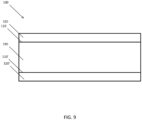
- the optical system 100 depicted in Fig. 9 includes a first coating 320 on a first exterior surface 310 of an LOE 190, and a second coating 322' on a second exterior surface 310' of the LOE 190.
- This second coating 322' can prevent in-coupling of select real-world light beams (e.g., high AOI) from a second direction into the LOE 190.
- embodiments described herein include at least partially transparent coatings 320, other embodiments may include other "diverters" for changing a light path of select real-world light beams (e.g., high AOI) such that the real-world light beams are not in-coupled into an LOE.
- diverters include various "lossy substances,” such as metasurface materials, and waveguide outcouplers.
- While the embodiments described herein include diverters (e.g., coatings) that reflect select real-world light beams, other embodiments include diverters that change a light path of select real-world light beams. Such diverters may refract or diffract the select real-world light beams.
- AR systems are provided as examples of various optical systems that can benefit from more selectively reflective optical elements. Accordingly, use of the optical systems described herein is not limited to the disclosed AR systems, but rather applicable to any optical system.
- the invention includes methods that may be performed using the subject devices.
- the methods may comprise the act of providing such a suitable device. Such provision may be performed by the end user.
- the "providing" act merely requires the end user obtain, access, approach, position, set-up, activate, power-up or otherwise act to provide the requisite device in the subject method.
- Methods recited herein may be carried out in any order of the recited events which is logically possible, as well as in the recited order of events.
- any optional feature of the inventive variations described may be set forth and claimed independently, or in combination with any one or more of the features described herein.
- Reference to a singular item includes the possibility that there are plural of the same items present. More specifically, as used herein and in claims associated hereto, the singular forms “a,” “an,” “said,” and “the” include plural referents unless the specifically stated otherwise.
- use of the articles allow for "at least one" of the subject item in the description above as well as claims associated with this disclosure.
- claims may be drafted to exclude any optional element. As such, this statement is intended to serve as antecedent basis for use of such exclusive terminology as “solely,” “only” and the like in connection with the recitation of claim elements, or use of a “negative” limitation.
Landscapes
- Physics & Mathematics (AREA)
- General Physics & Mathematics (AREA)
- Optics & Photonics (AREA)
- Optical Filters (AREA)
- Polarising Elements (AREA)
- Surface Treatment Of Optical Elements (AREA)
- Processing Or Creating Images (AREA)
- User Interface Of Digital Computer (AREA)
- Optical Couplings Of Light Guides (AREA)
Abstract
Description
- This application claims priority to
U.S. Provisional Application Serial Number 62/319,566, filed on April 7, 2016 U.S. Utility Patent Application Serial Number 14/331,218 filed on July 14, 2014 U.S. Utility Patent Application Serial Number 14/555,585 filed on November 27, 2014 U.S. Utility Patent Application Serial Number 14/726,424 filed on May 29, 2015 U.S. Utility Patent Application Serial Number 14/726,429 filed on May 29, 2015 U.S. Utility Patent Application Serial Number 14/726,396 filed under on May 29, 2015 - Modern computing and display technologies have facilitated the development of systems for so called "augmented reality" experiences, wherein digitally reproduced images or portions thereof are presented to a user in a manner wherein they seem to be, or may be perceived as, real. An augmented reality, or "AR", scenario typically involves presentation of digital or virtual image information as an augmentation to visualization of the actual world around the user (i.e., transparency to other actual real-world visual input). Accordingly, AR scenarios involve presentation of digital or virtual image information with transparency to other actual real-world visual input. The human visual perception system is very complex, and producing an AR technology that facilitates a comfortable, natural-feeling, rich presentation of virtual image elements amongst other virtual or real-world imagery elements is challenging.
- The visualization center of the brain gains valuable perception information from the motion of both eyes and components thereof relative to each other. Vergence movements (i.e., rolling movements of the pupils toward or away from each other to converge the lines of sight of the eyes to fixate upon an object) of the two eyes relative to each other are closely associated with focusing (or "accommodation") of the lenses of the eyes. Under normal conditions, changing the focus of the lenses of the eyes, or accommodating the eyes, to focus upon an object at a different distance will automatically cause a matching change in vergence to the same distance, under a relationship known as the "accommodation-vergence reflex." Likewise, a change in vergence will trigger a matching change in accommodation, under normal conditions. Working against this reflex, as do most conventional stereoscopic AR configurations, is known to produce eye fatigue, headaches, or other forms of discomfort in users.
- Stereoscopic wearable glasses generally feature two displays for the left and right eyes that are configured to display images with slightly different element presentation such that a three-dimensional perspective is perceived by the human visual system. Such configurations have been found to be uncomfortable for many users due to a mismatch between vergence and accommodation ("vergence-accommodation conflict") which must be overcome to perceive the images in three dimensions. Indeed, some AR users are not able to tolerate stereoscopic configurations. Accordingly, most conventional AR systems are not optimally suited for presenting a rich, binocular, three-dimensional experience in a manner that will be comfortable and maximally useful to the user, in part because prior systems fail to address some of the fundamental aspects of the human perception system, including the vergence-accommodation conflict.
- AR systems must also be capable of displaying virtual digital content at various perceived positions and distances relative to the user. The design of AR systems also presents numerous other challenges, including the speed of the system in delivering virtual digital content, quality of virtual digital content, eye relief of the user (addressing the vergence-accommodation conflict), size and portability of the system, and other system and optical challenges.
- One possible approach to address these problems (including the vergence-accommodation conflict) is to project images at multiple depth planes. To implement this type of system, one approach is to use a plurality of light-guiding optical elements to direct light at the eyes of a user such that the light appears to originate from multiple depth planes. The light-guiding optical elements are designed to in-couple virtual light corresponding to digital or virtual objects and propagate it by total internal reflection ("TIR"), then to out-couple the virtual light to display the digital or virtual objects to the user's eyes. The light-guiding optical elements are also designed be transparent to light from (e.g., reflecting off of) actual real-world objects. Therefore, portions of the light-guiding optical elements are designed to reflect virtual light for propagation via TIR while being transparent to real-world light from real-world objects.
- However, some real-world light can be in-coupled into the light-guiding optical element and out-couple in an uncontrolled manner, resulting in an unintended image of a real-world object being presented to the user's eyes. The appearance of unintended images of real-world objects in an AR scenario can disrupt the intended effect of the AR scenario. The appearance of unintended images in random locations in the field of view can also result in discomfort from vergence-accommodation conflict. The systems and methods described herein are configured to address these challenges.
- In one embodiment, an augmented reality system includes a light source configured to generate a virtual light beam. The system also includes a light guiding optical element having an entry portion, an exit portion, and a surface having a diverter disposed adjacent thereto. The light source and the light guiding optical element are configured such that the virtual light beam enters the light guiding optical element through the entry portion, propagates through the light guiding optical element by at least partially reflecting off of the surface, and exits the light guiding optical element through the exit portion. The light guiding optical element is transparent to a first real-world light beam. The diverter is configured to modify a light path of a second real-world light beam at the surface.
- In one or more embodiments, the diverter is configured to reflect the second real-world light beam. The diverter may be configured to refract or diffract the second real-world light beam.
- In one or more embodiments, the diverter is wavelength selective. The light source may be configured such that the virtual light beam has a wavelength corresponding to a wavelength for which the diverter is at least partially reflective.
- In one or more embodiments, the diverter is angle of incidence selective. The light source and the light guiding optical element may be configured such that the virtual light beam reflects off of the surface at an angle of incidence corresponding to an angle of incidence at which the diverter is reflective.
- In one or more embodiments, the diverter is polarization selective. The virtual light beam may be a polarization corresponding to a polarization for which the diverter is reflective.
- In one or more embodiments, the diverter is configured to reduce a critical angle of the surface compared to the surface without the diverter. The diverter may be a thin film dichroic diverter.
- In one or more embodiments, the light guiding optical element also has a second surface, where the light source and the light guiding optical element are configured such that the virtual light beam propagates through the light guiding optical element by at least partially reflecting off of the surface and the second surface. The light guiding optical element may also have a second diverter disposed adjacent the second surface, where the second diverter is configured to modify a light path of a third real-world light beam at the surface.
- In one or more embodiments, the diverter is a coating. The coating may be a dynamic coating. The dynamic coating may include a dielectric material, a liquid crystal, or lithium niobate. The diverter may include a metasurface material. The diverter may be a waveguide outcoupler.
- In another embodiment, an augmented reality system includes a light source configured to generate a virtual light beam. The system also includes a light guiding optical element having an entry portion, an exit portion, a first surface, and a second surface. The first surface has a first diverter disposed adjacent thereto. The second surface has a second diverter disposed adjacent thereto. The light source and the light guiding optical element are configured such that the virtual light beam enters the light guiding optical element through the entry portion, propagates through the light guiding optical element by at least partially reflecting off of both the first and second surfaces, and exits the light guiding optical element through the exit portion. The light guiding optical element is transparent to a first real-world light beam. The first and second diverters are each configured to modify reflection of a second real-world light beam at the respective first and second surfaces.
- In one or more embodiments, the first and second diverters are each configured to reflect the second real-world light beam.
- The drawings illustrate the design and utility of various embodiments of the present invention. It should be noted that the figures are not drawn to scale and that elements of similar structures or functions are represented by like reference numerals throughout the figures. In order to better appreciate how to obtain the above-recited and other advantages and objects of various embodiments of the invention, a more detailed description of the present inventions briefly described above will be rendered by reference to specific embodiments thereof, which are illustrated in the accompanying drawings. Understanding that these drawings depict only typical embodiments of the invention and are not therefore to be considered limiting of its scope, the invention will be described and explained with additional specificity and detail through the use of the accompanying drawings in which:
-
Figs. 1 to 3 are detailed schematic views of various augmented reality systems; -
Fig. 4 is a diagram depicting the focal planes of an augmented reality system; -
Fig. 5 is a detailed schematic view of a light-guiding optical element of an augmented reality system; -
Fig. 6 is an edge-on schematic view of a prior art light-guiding optical element of an augmented reality system; -
Fig. 7 is an edge-on schematic view of a light-guiding optical element of an augmented reality system according to one embodiment; and -
Fig. 8 is an edge-on schematic view of a coated surface of a light-guiding optical element of an augmented reality system according to one embodiment. - Various embodiments of the invention are directed to systems, methods, and articles of manufacture for implementing optical systems in a single embodiment or in multiple embodiments. Other objects, features, and advantages of the invention are described in the detailed description, figures, and claims.
- Various embodiments will now be described in detail with reference to the drawings, which are provided as illustrative examples of the invention so as to enable those skilled in the art to practice the invention. Notably, the figures and the examples below are not meant to limit the scope of the present invention. Where certain elements of the present invention may be partially or fully implemented using known components (or methods or processes), only those portions of such known components (or methods or processes) that are necessary for an understanding of the present invention will be described, and the detailed descriptions of other portions of such known components (or methods or processes) will be omitted so as not to obscure the invention. Further, various embodiments encompass present and future known equivalents to the components referred to herein by way of illustration.
- The optical systems may be implemented independently of AR systems, but many embodiments below are described in relation to AR systems for illustrative purposes only.
- One type of optical system for generating virtual images at various depths while allowing real-world light to pass through includes at least partially transparent light-guiding optical elements (e.g., prisms including diffractive optical elements). However, these light-guiding optical elements can unintentionally in-couple real-world light from real-world objects. The accidentally in-coupled real-world light can out-couple from the light-guiding optical elements toward a user's eyes. The out-coupled real-world light exits the light-guiding optical element with a changed angle, thereby generating artifacts in the AR scenario such as a "ghost" image or artifact of the sun appearing below the horizon. Not only does the ghost artifact disrupt the effect of the AR scenario with an incongruous and out of context image, it can also cause user discomfort from the vergence-accommodation conflict.
- The following disclosure describes various embodiments of systems and methods for creating 3D perception using multiple-plane focus optical elements that address this problem, by applying one or more coatings to one or more surfaces of the light-guiding optical elements. In particular, the coatings can be angularly selective such that the coated optical elements are substantially transparent to real-world light with a low angle of incidence ("AOI"; e.g., near 90 degrees from the surface of the optical element). At the same time, the coating renders the coated optical elements highly reflective to oblique real-world light with a high AOI (e.g., nearly parallel to the surface of the optical element; about 170 degrees). As such, the coated light-guiding optical element can be substantially transparent to real-world light in the field of view, while minimizing unintended in-coupling of real-world light and the ghost artifacts associated therewith.
- Before describing the details of embodiments of the coated light-guiding optical elements, this disclosure will now provide a brief description of illustrative AR systems.
- One possible approach to implementing an AR system uses a plurality of volume phase holograms, surface-relief holograms, or light-guiding optical elements that are embedded with depth plane information to generate images that appear to originate from respective depth planes. In other words, a diffraction pattern, or diffractive optical element ("DOE") may be embedded within or imprinted upon a light-guiding optical element ("LOE"; e.g., a planar waveguide) such that as collimated light (light beams with substantially planar wavefronts) is substantially totally internally reflected along the LOE, it intersects the diffraction pattern at multiple locations and exits toward the user's eye. The DOEs are configured so that light exiting therethrough from an LOE are verged so that they appear to originate from a particular depth plane. The collimated light may be generated using an optical condensing lens (a "condenser").
- For example, a first LOE may be configured to deliver collimated light to the eye that appears to originate from the optical infinity depth plane (0 diopters). Another LOE may be configured to deliver collimated light that appears to originate from a distance of 2 meters (1/2 diopter). Yet another LOE may be configured to deliver collimated light that appears to originate from a distance of 1 meter (1 diopter). By using a stacked LOE assembly, it can be appreciated that multiple depth planes may be created, with each LOE configured to display images that appear to originate from a particular depth plane. It should be appreciated that the stack may include any number of LOEs. However, at least N stacked LOEs are required to generate N depth planes. Further, N, 2N or 3N stacked LOEs may be used to generate RGB colored images at N depth planes.
- In order to present 3D virtual content to the user, the augmented reality (AR) system projects images of the virtual content into the user's eye so that they appear to originate from various depth planes in the Z direction (i.e., orthogonally away from the user's eye). In other words, the virtual content may not only change in the X and Y directions (i.e., in a 2D plane orthogonal to a central visual axis of the user's eye), but it may also appear to change in the Z direction such that the user may perceive an object to be very close or at an infinite distance or any distance in between. In other embodiments, the user may perceive multiple objects simultaneously at different depth planes. For example, the user may see a virtual dragon appear from infinity and run towards the user. Alternatively, the user may simultaneously see a virtual bird at a distance of 3 meters away from the user and a virtual coffee cup at arm's length (about 1 meter) from the user.
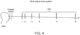
- Multiple-plane focus systems create a perception of variable depth by projecting images on some or all of a plurality of depth planes located at respective fixed distances in the Z direction from the user's eye. Referring now to
Fig. 4 , it should be appreciated that multiple-plane focus systems typically display frames at fixed depth planes 202 (e.g., the sixdepth planes 202 shown inFig. 4 ). Although AR systems can include any number ofdepth planes 202, one exemplary multiple-plane focus system has six fixeddepth planes 202 in the Z direction. In generating virtual content one or more of the sixdepth planes 202, 3D perception is created such that the user perceives one or more virtual objects at varying distances from the user's eye. Given that the human eye is more sensitive to objects that are closer in distance than objects that appear to be far away,more depth planes 202 are generated closer to the eye, as shown inFig. 4 . In other embodiments, the depth planes 202 may be placed at equal distances away from each other. - Depth plane positions 202 are typically measured in diopters, which is a unit of optical power equal to the inverse of the focal length measured in meters. For example, in one embodiment,
depth plane 1 may be 1/3 diopters away,depth plane 2 may be 0.3 diopters away,depth plane 3 may be 0.2 diopters away,depth plane 4 may be 0.15 diopters away,depth plane 5 may be 0.1 diopters away, anddepth plane 6 may represent infinity (i.e., 0 diopters away). It should be appreciated that other embodiments may generatedepth planes 202 at other distances/diopters. Thus, in generating virtual content at strategically placeddepth planes 202, the user is able to perceive virtual objects in three dimensions. For example, the user may perceive a first virtual object as being close to him when displayed indepth plane 1, while another virtual object appears at infinity atdepth plane 6. Alternatively, the virtual object may first be displayed atdepth plane 6, thendepth plane 5, and so on until the virtual object appears very close to the user. It should be appreciated that the above examples are significantly simplified for illustrative purposes. In another embodiment, all six depth planes may be concentrated on a particular focal distance away from the user. For example, if the virtual content to be displayed is a coffee cup half a meter away from the user, all six depth planes could be generated at various cross-sections of the coffee cup, giving the user a highly granulated 3D view of the coffee cup. - In one embodiment, the AR system may work as a multiple-plane focus system. In other words, all six LOEs may be illuminated simultaneously, such that images appearing to originate from six fixed depth planes are generated in rapid succession with the light sources rapidly conveying image information to
LOE 1, thenLOE 2, thenLOE 3 and so on. For example, a portion of the desired image, comprising an image of the sky at optical infinity may be injected attime 1 and the LOE 1090 retaining collimation of light (e.g.,depth plane 6 fromFig. 4 ) may be utilized. Then an image of a closer tree branch may be injected attime 2 and an LOE 1090 configured to create an image appearing to originate from a depth plane 10 meters away (e.g.,depth plane 5 fromFig. 4 ) may be utilized; then an image of a pen may be injected attime 3 and an LOE 1090 configured to create an image appearing to originate from adepth plane 1 meter away may be utilized. This type of paradigm can be repeated in rapid time sequential (e.g., at 360 Hz) fashion such that the user's eye and brain (e.g., visual cortex) perceives the input to be all part of the same image. - AR systems are required to project images (i.e., by diverging or converging light beams) that appear to originate from various locations along the Z axis (i.e., depth planes) to generate images for a 3D experience. As used in this application, light beams include, but are not limited to, directional projections of light energy (including visible and invisible light energy) radiating from a light source. Generating images that appear to originate from various depth planes conforms the vergence and accommodation of the user's eye for that image, and minimizes or eliminates vergence-accommodation conflict.
-
Fig. 1 depicts a basicoptical system 100 for projecting images at a single depth plane. Thesystem 100 includes alight source 120 and anLOE 190 having a diffractive optical element (not shown) and an in-coupling grating 192 (ICG) associated therewith. The diffractive optical elements may be of any type, including volumetric or surface relief. In one embodiment, theICG 192 is a reflection-mode aluminized portion of theLOE 190. In another embodiment, theICG 192 is a transmissive diffractive portion of theLOE 190. When thesystem 100 is in use, the light beam from thelight source 120 enters theLOE 190 via theICG 192 and propagates along theLOE 190 by substantially total internal reflection ("TIR") for display to an eye of a user. It is understood that although only one beam is illustrated inFig. 1 , a multitude of beams may enterLOE 190 from a wide range of angles through thesame ICG 192. A light beam "entering" or being "admitted" into an LOE includes, but is not limited to, the light beam interacting with the LOE so as to propagate along the LOE by substantially TIR. Thesystem 100 depicted inFig. 1 can include various light sources 120 (e.g., LEDs, OLEDs, lasers, and masked broad-area/broad-band emitters). In other embodiments, light from thelight source 120 may be delivered to theLOE 190 via fiber optic cables (not shown). -
Fig. 2 depicts another optical system 100', which includes alight source 120, threeLOEs 190, and three respective in-coupling gratings 192. The optical system 100' also includes three beam-splitters or dichroic mirrors 162 (to direct light to the respective LOEs) and three LC shutters 164 (to control when the LOEs are illuminated). When the system 100' is in use, the light beam from thelight source 120 is split into three sub-beams/beamlets by the three-beam-splitters 162. The three beam-splitters also redirect the beamlets toward respective in-coupling gratings 192. After the beamlets enter theLOEs 190 through the respective in-coupling gratings 192, they propagate along theLOEs 190 by substantially TIR where they interact with additional optical structures resulting in display to an eye of a user. The surface of in-coupling gratings 192 on the far side of the optical path can be coated with an opaque material (e.g., aluminum) to prevent light from passing through the in-coupling gratings 192 to thenext LOE 190. In one embodiment the beam-splitters 162 can be combined with wavelength filters to generate red, green and blue beam lets. In such an embodiment, threeLOEs 190 are required to display a color image at a single depth plane. In another embodiment,LOEs 190 may each present a portion of a larger, single depth-plane image area angularly displaced laterally within the user's field of view, either of like colors, or different colors ("tiled field of view"). -
Fig. 3 depicts still anotheroptical system 100", having six beam-splitters 162, sixLC shutters 164 and sixLOEs 190, each having arespective ICG 192. As explained above during the discussion ofFig. 2 , threeLOEs 190 are required to display a color image at a single depth plane. Therefore, the sixLOEs 190 of thissystem 100" are able to display color images at two depth planes. -
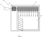
Fig. 5 depicts aLOE 190 having anICG 192, an orthogonal pupil expander 194 ("OPE"), and an exit pupil expander 196 ("EPE"). - As shown in
Figs. 1-4 , as the number of depth planes, field tiles, or colors generated increases (e.g., with increased AR scenario quality), the numbers ofLOEs 190 andICGs 192 increases. For example, a single RGB color depth plane requires at least threeLOEs 190 with threeICGs 192. As a result, the opportunity for inadvertent in-coupling of real-world light at these optical elements also increases. Further, real-world light can be in-coupled all along anLOE 190, including at out-coupling gratings (not shown). Thus the increasing number of optical elements required to generate an acceptable AR scenario exacerbates the problem of ghost artifacts from in-coupled real-world light. - The
LOEs 190 discussed above can additionally function as exit pupil expanders 196 ("EPE") to increase the numerical aperture of alight source 120, thereby increasing the resolution of thesystem 100. Since thelight source 120 produces light of a small diameter/spot size, theEPE 196 expands the apparent size of the pupil of light exiting from theLOE 190 to increase the system resolution. In other embodiments of theAR system 100, the system may further comprise an orthogonal pupil expander 194 ("OPE") in addition to anEPE 196 to expand the light in both the X and Y directions. More details about theEPEs 196 andOPEs 194 are described in the above-referencedU.S. Utility Patent Application Serial Number 14/555,585 andU.S. Utility Patent Application Serial Number 14/726,424 , the contents of which have been previously incorporated by reference. -
Fig. 5 depicts anLOE 190 having anICG 192, anOPE 194 and anEPE 196.Fig. 5 depicts theLOE 190 from a top view that is similar to the view from a user's eyes. TheICG 192,OPE 194, andEPE 196 may be any type of DOE, including volumetric or surface relief. - The
ICG 192 is a DOE (e.g., a linear grating) that is configured to admit light from alight source 120 for propagation by TIR. In the embodiment depicted inFig. 5 , thelight source 120 is disposed to the side of theLOE 190. - The
OPE 194 is a DOE (e.g., a linear grating) that is slanted in the lateral plane (i.e., perpendicular to the light path) such that a light beam that is propagating through thesystem 100 will be deflected by 90 degrees laterally. TheOPE 194 is also partially transparent and partially reflective along the light path, so that the light beam partially passes through theOPE 194 to form multiple (e.g., 11) beamlets. In one embodiment, the light path is along an X axis, and theOPE 194 configured to bend the beam lets to the Y axis. - The
EPE 196 is a DOE (e.g., a linear grating) that is slanted in the axial plane (i.e., parallel to the light path or the Y direction) such that the beamlets that are propagating through thesystem 100 will be deflected by 90 degrees axially. TheEPE 196 is also partially transparent and partially reflective along the light path (the Y axis), so that the beamlets partially pass through theEPE 196 to form multiple (e.g., 7) beamlets. TheEPE 196 is also slated in a Z direction to direction portions of the propagating beamlets toward a user's eye. - The
OPE 194 and theEPE 196 are both also at least partially transparent along the Z axis to allow real-world light (e.g., reflecting off real-world objects) to pass through theOPE 194 and theEPE 196 in the Z direction to reach the user's eyes. In some embodiments, theICG 192 is at least partially transparent along the Z axis also at least partially transparent along the Z axis to admit real-world light. However, when theICG 192,OPE 194, or theEPE 196 are transmissive diffractive portions of theLOE 190, they may unintentionally in-couple real-world light may into theLOE 190. As described above this unintentionally in-coupled real-world light may be out-coupled into the eyes of the user forming ghost artifacts. -
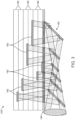
Fig. 6 is an edge-on schematic view of a priorart AR system 100 having anLOE 190. TheLOE 190 is similar to the one depicted inFig. 5 , but only theICG 192 and theEPE 196 are depictedFig. 6 , with theOPE 194 omitted for clarity. Several exemplary light beams from various sources are illustrated to demonstrate the ghost artifact problem mentioned above. Avirtual light beam 302 generated by alight source 120 is in-coupled into theLOE 190 by theICG 192. Thevirtual light beam 302 carries information for a virtual object generated by theAR system 100. - The
virtual light beam 302 is propagated throughLOE 190 by TIR, and partially exits each time it impinges on theEPE 196. InFig. 6 , thevirtual light beam 302 impinges two locations on theEPE 196. The exiting virtual light beamlets 302' address a user'seye 304 at an angle determined by theAR system 100. The virtual light beamlets 302' depicted inFig. 6 are substantially parallel to each other. The virtual light beamlets 302' will therefore render an image (e.g., a distant flock of birds; not shown) that appears to originate from near infinity. The virtual light beamlets 302' can address a user'seye 304 at a wide range of angles relative to each other to render images that appear to originate from a wide range of distances from the user's eye. - The
LOE 190 is also transparent to real-world light beams 306, such as those reflecting off of real-world objects 308 (e.g., a distant tree). Because thetree 308 depicted inFig. 6 is distant from user'seye 304, the real-world light beams 302 are substantially parallel to each other. The real-world light beams 306 pass through theLOE 190 without noticeably changing trajectory, because theLOE 190 is transparent to light impinging on theLOE 190 at a relatively low AOI (e.g., about 90 degrees from anexterior surface 310 of the LOE 190). Real-world objects 308 at distances closer to the user'seye 302 will diverge from each other, but will still substantially pass through theLOE 190. - The problem is that this
prior art LOE 190 also in-couples (by refraction) high AOI real-world light beams 312 that address theLOE 190 at a high AOI (e.g., about parallel to the surface of theLOE 190; about 170 degrees). For instance, the high AOI object 314 (i.e., the sun) depicted inFig. 6 is at a high AOI relative to theLOE 190. While thesun 314 is depicted to the right of theLOE 190, thesun 314 can be, and typically is, high in the sky above theLOE 190. - The
sun 314 is ahigh AOI object 314 that can generate ghost artifacts because it is also bright.Other objects 314 that can generate ghost artifacts include light sources (flashlights, lamps, headlights, etc.) that happen to impinge on anLOE 190 at a high AOI. - As shown in
Fig. 6 , the high AOI real-world beam 312 can be in-coupled into theLOE 190 at anexterior surface 310 of theLOE 190. Due to the index of refraction of the material from which theLOE 190 is made, the in-coupled high AOI real-world beam 312' changes trajectory from the high AOI real-world beam 312. Finally, when the in-coupled high AOI real-world beam 312' impinges on theEPE 196, it exits theLOE 190 as an exiting high AOI real-world beam 312" with a further changed trajectory. As shown inFig. 6 , the exiting high AOI real-world beam 312" renders a ghost image/artifact 316 of the sun that appears to originate from a different location in the field of view than the actual location of thesun 314. InFig. 6 , the ghost image/artifact 316 appears to originate in the same location as thetree 308. The juxtaposition of the unintended ghost image/artifact 316 of thesun 314 over the real-world tree 308 can disrupt the intended effect of the AR scenario. The appearance of unintended ghost images/artifacts 316 can also result in discomfort from vergence-accommodation conflict, because the ghost image/artifact 316 will appear with a random degree of focus. - Because
AR systems 100 require some degree of transparency to real-world light beams 306, theirLOEs 190 have the problem of unintended in-coupling of high AOI real-world light beams 312, and the ghost artifacts generated when the in-coupled high AOI real-world beam 312' exits theLOE 190. While singles beams and beam lets are depicted inFig. 6 , it should be appreciated that this is for clarity. Each single beam or beamlet depicted inFig. 6 represents a plurality of beams or beamlets carrying related information and having similar trajectories. -
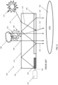
Fig. 7 is an edge-on schematic view of anAR system 100 having anLOE 190 according to one embodiment. TheLOE 190 has anICG 192, an OPE (not shown), anEPE 196, and a selectivelyreflective coating 320. The selectivelyreflective coating 320 is disposed on anexternal surface 310 of theLOE 190. The selectivelyreflective coating 320 can be configured to reflect light having a variety of characteristics, depending how thecoating 320 is "tuned." In one embodiment, the coating is tuned to selectively reflect light impinging upon thecoating 320 at a relatively high AOI, while allowing light impinging upon thecoating 320 at a relatively low AOI to pass through the coating. Thecoating 320 is also tuned to allow relatively low AOI light to pass therethrough without noticeably changing the angle of trajectory thereof. - Tuning a
coating 320 involves selecting the physical dimensions and chemical makeup of a coating to control its reflection characteristics. For instance, thecoating 320 may include a plurality of thin layers, as depicted inFig. 8 . Theentire coating 320 or one or more layers therein may include dichroic materials, or other materials with differential reflectance of light based on the light's characteristics (e.g., wavelength, AOI, and/or polarization). Layers having different reflectance characteristics can be combined to tune thecoating 320. - In one embodiment, the
coating 320 can be tuned to achieve target reflectance at various AOIs. Coating design software can determine a number of layers and the indices for each layer to achieve the target reflectance. Starting with a standard stack of indices and thicknesses (e.g., from a mirror designer), the software can determine a closed form solution to the structure as a function of AOI or wavelength. Increasing the number of layers in thecoating 320 and/or the indices and thicknesses of those layers facilitates a more complex reflectance vs. AOI profile, including sharp cut-offs in terms of AOI and reflectance. With a single layer and a single index of material, thecoating 320 can be a V-coat (i.e., anti-reflective material at one wavelength and one angle). With two layers thecoating 320 can be a W-coat (i.e., anti-reflective material at two wavelengths and two angle). The coating design technique is analogous to techniques used to design biological filters for florescence microscopy with many layers and extremely sharp wavelength cut-offs. Examples ofcoatings 320 include dynamic coating such as dielectric coatings, liquid crystal coatings, and lithium niobate coatings. - The
system 100 also includes alight source 120 configured to direct avirtual light beam 302 at theICG 192. Thevirtual light beam 302 is in-coupled into theLOE 190 by theICG 192. Thevirtual light beam 302 carries information for a virtual object generated by theAR system 100. - The
virtual light beam 302 is propagated throughLOE 190 by TIR, and partially exits each time it impinges on theEPE 196. Thecoating 320 is tuned to selectively reflect light with AOI greater than or equal to the critical angle of thesystem 100, thereby facilitating TIR. In other embodiments, thecoating 320 can be tuned to reduce the critical angle of theLOE 190 to further facilitate TIR. - In
Fig. 7 , thevirtual light beam 302 impinges two locations on theEPE 196. The exiting virtual light beamlets 302' address a user'seye 304 at an angle determined by theAR system 100. The virtual light beamlets 302' depicted inFig. 6 are substantially parallel to each other. The virtual light beamlets 302' will therefore render an image (e.g., a distant flock of birds; not shown) that appears to originate from near infinity. The virtual light beamlets 302' can address a user'seye 304 at a wide range of angles relative to each other to render images that appear to originate from a wide range of distances from the user's eye. - The
LOE 190 is also substantially transparent to real-world light beams 306, such as those reflecting off of real-world objects 308 (e.g., a distant tree). Thecoating 320 applied to theLOE 190 is also tuned to be substantially transparent to real-world light beams 306 with an AOI less than the critical angle of thesystem 100. Because thetree 308 depicted inFig. 6 is distant from user'seye 304, the real-world light beams 302 are substantially parallel to each other. The real-world light beams 306 pass through theLOE 190 without noticeably changing trajectory, because theLOE 190 is substantially transparent to light impinging on theLOE 190 at a relatively low AOI (e.g., about 90 degrees from anexterior surface 310 of the LOE 190). Real-world objects 308 at distances closer to the user'seye 302 will diverge from each other, but will still substantially pass through theLOE 190 and thecoating 320. - When a high AOI real-
world light beam 312 impinges on theLOE 190 at a high AOI (e.g., about parallel to the surface of the LOE 190), the high AOI real-world light beam 312 is selectively reflected by thecoating 320, and does not in-couple into theLOE 190. Thecoating 320 is tuned to selectively reflect the high AOI real-world light beam 312 because of its high AOI. As shown inFig. 7 , the reflected high AOI real-world beam 312‴ is directed away from theLOE 190 and does not impinge upon the user'seye 304. Because the reflected high AOI real-world beam 312‴ does not reach the user'seye 304, no ghost artifacts are generated in the user's field of view. - In the above-described manner, the selectively
reflective coating 320 reduces or eliminates ghost artifacts, while maintaining the degree of transparency to real-world light beams 306 required ofAR systems 100. Thecoating 320 substantially prevents theLOEs 190 from in-coupling high AOI real-world light beams 312. - The
coating 320 may also be tuned to be selective for characteristics of thevirtual light beam 302 to promote TIR of thereof. In one embodiment, thecoating 320 is tuned to reflect or reflect to a greater degree light of a certain wavelength, and thelight source 120 can be configured such that thevirtual light beam 302 has that certain wavelength. In another embodiment, thecoating 320 is tuned to reflect or reflect to a greater degree light having a certain AOI, and thesystem 100 can be configured such that thevirtual light beam 302 has that certain AOI. In still another embodiment, thecoating 320 is tuned to reflect or reflect to a greater degree light having a certain polarization, and thesystem 100 can be configured such that thevirtual light beam 302 has that certain polarization. In yet another embodiment, thecoating 320 is tuned to reduce a critical angle of theexterior surface 310. In still another embodiment, thecoating 320 is tuned to reflect light at one or more wavelengths to which a user's eye is most sensitive (e.g., 520 nm or 532 nm "green" light), to thereby prevent unintentional in-coupling of that light. - While singles beams and beamlets are depicted in
Fig. 6 , it should be appreciated that this is for clarity. Each single beam or beamlet depicted inFig. 6 represents a plurality of beams or beamlets carrying related information and having similar trajectories. - While the
coating 320 may reduce the field of view by reflecting real-world high AOI light, reduction or elimination of ghost artifacts is a benefit that can outweigh the cost of a reduced field of view. Further, thecoating 320 may be tuned to reduce ghost artifacts while retaining an acceptable field of view. - While the embodiments described herein include a single
coated surface 310, other embodiments have two or morecoated surfaces 310 to reduce unintended in-coupling of high AOI real-world light beams 312 at all of the coated surfaces 310. In embodiments, where asingle surface 310 is coated, afront facing surface 310 is preferably coated, because thefront facing surface 310 will be most exposed to high AOI real-world light beams 312. - While the embodiments described herein include a coated
exterior surface 310, thecoating 320 or the structural and chemical equivalent thereof can be incorporated into theLOE 190. In some embodiments, thecoating 320 or the structural and chemical equivalent thereof is disposed at an interior surface of theLOE 190. In other embodiments, thecoating 320 or the structural and chemical equivalent thereof is disposed in the middle of theLOE 190. Embodiments include all possible positions as long as thecoating 320 or the structural and chemical equivalent thereof reflects high AOI real-world light beams 312 and prevent them from in-coupling into theLOE 190. - While the embodiments described herein include a
coating 320 on oneexterior surface 310 of anLOE 190, other embodiments include a plurality of coatings on a plurality of surfaces. For instance, theoptical system 100 depicted inFig. 9 includes afirst coating 320 on a firstexterior surface 310 of anLOE 190, and a second coating 322' on a second exterior surface 310' of theLOE 190. This second coating 322' can prevent in-coupling of select real-world light beams (e.g., high AOI) from a second direction into theLOE 190. - While the embodiments described herein include at least partially
transparent coatings 320, other embodiments may include other "diverters" for changing a light path of select real-world light beams (e.g., high AOI) such that the real-world light beams are not in-coupled into an LOE. Examples of diverters include various "lossy substances," such as metasurface materials, and waveguide outcouplers. - While the embodiments described herein include diverters (e.g., coatings) that reflect select real-world light beams, other embodiments include diverters that change a light path of select real-world light beams. Such diverters may refract or diffract the select real-world light beams.
- The above-described AR systems are provided as examples of various optical systems that can benefit from more selectively reflective optical elements. Accordingly, use of the optical systems described herein is not limited to the disclosed AR systems, but rather applicable to any optical system.
- Various exemplary embodiments of the invention are described herein. Reference is made to these examples in a non-limiting sense. They are provided to illustrate more broadly applicable aspects of the invention. Various changes may be made to the invention described and equivalents may be substituted without departing from the true spirit and scope of the invention. In addition, many modifications may be made to adapt a particular situation, material, composition of matter, process, process act(s) or step(s) to the objective(s), spirit or scope of the present invention. Further, as will be appreciated by those with skill in the art that each of the individual variations described and illustrated herein has discrete components and features which may be readily separated from or combined with the features of any of the other several embodiments without departing from the scope or spirit of the present inventions. All such modifications are intended to be within the scope of claims associated with this disclosure.
- The invention includes methods that may be performed using the subject devices. The methods may comprise the act of providing such a suitable device. Such provision may be performed by the end user. In other words, the "providing" act merely requires the end user obtain, access, approach, position, set-up, activate, power-up or otherwise act to provide the requisite device in the subject method. Methods recited herein may be carried out in any order of the recited events which is logically possible, as well as in the recited order of events.
- Exemplary aspects of the invention, together with details regarding material selection and manufacture have been set forth above. As for other details of the present invention, these may be appreciated in connection with the above-referenced patents and publications as well as generally known or appreciated by those with skill in the art. The same may hold true with respect to method-based aspects of the invention in terms of additional acts as commonly or logically employed.
- In addition, though the invention has been described in reference to several examples optionally incorporating various features, the invention is not to be limited to that which is described or indicated as contemplated with respect to each variation of the invention. Various changes may be made to the invention described and equivalents (whether recited herein or not included for the sake of some brevity) may be substituted without departing from the true spirit and scope of the invention. In addition, where a range of values is provided, it is understood that every intervening value, between the upper and lower limit of that range and any other stated or intervening value in that stated range, is encompassed within the invention.
- Also, it is contemplated that any optional feature of the inventive variations described may be set forth and claimed independently, or in combination with any one or more of the features described herein. Reference to a singular item, includes the possibility that there are plural of the same items present. More specifically, as used herein and in claims associated hereto, the singular forms "a," "an," "said," and "the" include plural referents unless the specifically stated otherwise. In other words, use of the articles allow for "at least one" of the subject item in the description above as well as claims associated with this disclosure. It is further noted that such claims may be drafted to exclude any optional element. As such, this statement is intended to serve as antecedent basis for use of such exclusive terminology as "solely," "only" and the like in connection with the recitation of claim elements, or use of a "negative" limitation.
- Without the use of such exclusive terminology, the term "comprising" in claims associated with this disclosure shall allow for the inclusion of any additional element--irrespective of whether a given number of elements are enumerated in such claims, or the addition of a feature could be regarded as transforming the nature of an element set forth in such claims. Except as specifically defined herein, all technical and scientific terms used herein are to be given as broad a commonly understood meaning as possible while maintaining claim validity.
- The breadth of the present invention is not to be limited to the examples provided and/or the subject specification, but rather only by the scope of claim language associated with this disclosure.
- In the foregoing specification, the invention has been described with reference to specific embodiments thereof. It will, however, be evident that various modifications and changes may be made thereto without departing from the broader spirit and scope of the invention. For example, the above-described process flows are described with reference to a particular ordering of process actions. However, the ordering of many of the described process actions may be changed without affecting the scope or operation of the invention. The specification and drawings are, accordingly, to be regarded in an illustrative rather than restrictive sense.
Claims (15)
- An augmented reality system, comprising:a light source configured to generate a virtual light beam; anda planar waveguide having an entry portion, an exit portion, and a surface having a diverter disposed adjacent thereto,wherein the diverter is tuned to selectively:prevent real-world light beams that are incident on the diverter at angles greater than or equal to a predetermined angle of incidence from reaching the surface of the planar waveguide, andallow real-world light beams that are incident on the diverter at angles less than the angle of incidence to pass through the diverter to the surface of the planar waveguide, andwherein tuning the diverter comprises selecting a physical dimension and a chemical makeup of the diverter, andwherein the diverter is wavelength selective.
- The system of claim 1, wherein the diverter is configured to reflect the real-world light beams that are incident on the diverter at angles greater than or equal to the angle of incidence to prevent said real-world light beams from entering said planar waveguide through the surface of the planar waveguide.
- The system of claims 1 or 2, wherein the diverter is further configured to refract or diffract further real-world light beams.
- The system of any of claims 1-3, wherein the light source is configured such that the virtual light beam has a wavelength corresponding to a wavelength for which the diverter is at least partially reflective.
- The system of any of claims 1-4, wherein the diverter is polarization selective, and.
wherein the virtual light beam has a polarization corresponding to a polarization for which the diverter is reflective. - The system of any of claims 1-5, wherein the diverter is configured to reduce a critical angle of the surface of the planar waveguide compared to the surface of the planar waveguide without the diverter.
- The system of any of claims 1-6, the planar waveguide also having:a second surface, wherein the light source and the planar waveguide are configured such that the virtual light beam propagates through the planar waveguide by at least partially reflecting off of the surface of the planar waveguide and the second surface of the planar waveguide, anda second diverter disposed adjacent the second surface, wherein the second diverter is configured to selectively:prevent real-world light beams that are incident on the diverter at angles greater than or equal to the angle of incidence from reaching the second surface of the planar waveguide, andallow real-world light beams that are incident on the diverter at angles less than the angle of incidence to pass through the second diverter to the second surface of the planar waveguide.
- The system of any of claims 1-7, wherein the diverter is a coating, and
wherein the coating is a selectively reflective coating. - The system of any of claims 1-8, wherein the diverter is a dynamic coating comprising a liquid crystal or lithium niobate.
- The system of any of claims 1-9, wherein the diverter comprises a metasurface material.
- The system of any of claims 1-10, wherein the diverter is a waveguide outcoupler.
- The system of any of claims 1-11, wherein the diverter includes a plurality of thin layers having different reflectance characteristics.
- The system of claim 12, further comprising an in-coupling grating and orthogonal pupil expander.
- The system of any of claims 1-13, wherein the diverter is a thin film dichroic diverter.
- The system of any of claims 1-14, wherein the planar waveguide has a second surface having a second diverter disposed adjacent thereto, and
wherein the second diverter is tuned by selecting a physical dimension and a chemical makeup of the diverter to selectively:prevent real-world light beams that are incident on the second diverter at angles greater than or equal to a predetermined angle of incidence from reaching the respective second surface of the planar waveguide, andallow real-world light beams that are incident on the second diverter at angles less than the angle of incidence to pass through the second surface of the planar waveguide.
Applications Claiming Priority (3)
| Application Number | Priority Date | Filing Date | Title |
|---|---|---|---|
| US201662319566P | 2016-04-07 | 2016-04-07 | |
| EP17779729.7A EP3440486B1 (en) | 2016-04-07 | 2017-04-05 | Systems and methods for augmented reality |
| PCT/US2017/026102 WO2017176861A1 (en) | 2016-04-07 | 2017-04-05 | Systems and methods for augmented reality |
Related Parent Applications (2)
| Application Number | Title | Priority Date | Filing Date |
|---|---|---|---|
| EP17779729.7A Division-Into EP3440486B1 (en) | 2016-04-07 | 2017-04-05 | Systems and methods for augmented reality |
| EP17779729.7A Division EP3440486B1 (en) | 2016-04-07 | 2017-04-05 | Systems and methods for augmented reality |
Publications (2)
| Publication Number | Publication Date |
|---|---|
| EP4411454A2 true EP4411454A2 (en) | 2024-08-07 |
| EP4411454A3 EP4411454A3 (en) | 2024-11-27 |
Family
ID=59999340
Family Applications (2)
| Application Number | Title | Priority Date | Filing Date |
|---|---|---|---|
| EP24175612.1A Pending EP4411454A3 (en) | 2016-04-07 | 2017-04-05 | Systems and methods for augmented reality |
| EP17779729.7A Active EP3440486B1 (en) | 2016-04-07 | 2017-04-05 | Systems and methods for augmented reality |
Family Applications After (1)
| Application Number | Title | Priority Date | Filing Date |
|---|---|---|---|
| EP17779729.7A Active EP3440486B1 (en) | 2016-04-07 | 2017-04-05 | Systems and methods for augmented reality |
Country Status (10)
| Country | Link |
|---|---|
| US (3) | US11067797B2 (en) |
| EP (2) | EP4411454A3 (en) |
| JP (1) | JP7055751B2 (en) |
| KR (1) | KR20180125600A (en) |
| CN (1) | CN109073819A (en) |
| AU (1) | AU2017246864B2 (en) |
| CA (1) | CA3018782A1 (en) |
| IL (1) | IL261829B2 (en) |
| NZ (1) | NZ746486A (en) |
| WO (1) | WO2017176861A1 (en) |
Families Citing this family (78)
| Publication number | Priority date | Publication date | Assignee | Title |
|---|---|---|---|---|
| US10156722B2 (en) | 2010-12-24 | 2018-12-18 | Magic Leap, Inc. | Methods and systems for displaying stereoscopy with a freeform optical system with addressable focus for virtual and augmented reality |
| WO2015063762A1 (en) | 2013-10-28 | 2015-05-07 | Ramot At Tel-Aviv University Ltd. | System and method for controlling light |
| US9915826B2 (en) | 2013-11-27 | 2018-03-13 | Magic Leap, Inc. | Virtual and augmented reality systems and methods having improved diffractive grating structures |
| CN111856755B (en) | 2014-05-30 | 2022-07-19 | 奇跃公司 | Method and system for displaying stereoscopic vision of virtual and augmented reality |
| KR102282394B1 (en) | 2015-01-26 | 2021-07-26 | 매직 립, 인코포레이티드 | Virtual and augmented reality systems and methods with improved diffractive grating structures |
| EP3062142B1 (en) | 2015-02-26 | 2018-10-03 | Nokia Technologies OY | Apparatus for a near-eye display |
| WO2017176861A1 (en) | 2016-04-07 | 2017-10-12 | Magic Leap, Inc. | Systems and methods for augmented reality |
| ES2992065T3 (en) | 2016-08-16 | 2024-12-09 | Insight Medical Systems Inc | Sensory augmentation systems in medical procedures |
| US10650552B2 (en) | 2016-12-29 | 2020-05-12 | Magic Leap, Inc. | Systems and methods for augmented reality |
| EP3343267B1 (en) | 2016-12-30 | 2024-01-24 | Magic Leap, Inc. | Polychromatic light out-coupling apparatus, near-eye displays comprising the same, and method of out-coupling polychromatic light |
| US11841520B2 (en) | 2017-02-02 | 2023-12-12 | Technology Innovation Momentum Fund (Israel) Limited Partnership | Multilayer optical element for controlling light |
| US11835680B2 (en) | 2017-05-04 | 2023-12-05 | President And Fellows Of Harvard College | Meta-lens doublet for aberration correction |
| AU2018270948B2 (en) | 2017-05-16 | 2022-11-24 | Magic Leap, Inc. | Systems and methods for mixed reality |
| US10859834B2 (en) | 2017-07-03 | 2020-12-08 | Holovisions | Space-efficient optical structures for wide field-of-view augmented reality (AR) eyewear |
| US10338400B2 (en) | 2017-07-03 | 2019-07-02 | Holovisions LLC | Augmented reality eyewear with VAPE or wear technology |
| US10578870B2 (en) | 2017-07-26 | 2020-03-03 | Magic Leap, Inc. | Exit pupil expander |
| JP7461294B2 (en) * | 2017-08-31 | 2024-04-03 | メタレンズ,インコーポレイテッド | Transmissive metasurface lens integration |
| JP7282090B2 (en) * | 2017-12-10 | 2023-05-26 | マジック リープ, インコーポレイテッド | Antireflection coating on optical waveguide |
| CN111712751B (en) | 2017-12-20 | 2022-11-01 | 奇跃公司 | Insert for augmented reality viewing apparatus |
| FI129167B (en) * | 2017-12-22 | 2021-08-31 | Dispelix Oy | Interference-free waveguide display |
| FI128665B (en) * | 2017-12-22 | 2020-09-30 | Dispelix Oy | Improved brightness waveguide display |
| US10989921B2 (en) * | 2017-12-29 | 2021-04-27 | Letinar Co., Ltd. | Augmented reality optics system with pinpoint mirror |
| EP4415355A3 (en) | 2018-03-15 | 2024-09-04 | Magic Leap, Inc. | Image correction due to deformation of components of a viewing device |
| JP7650662B2 (en) | 2018-05-30 | 2025-03-25 | マジック リープ, インコーポレイテッド | Compact varifocal configuration |
| CN112601975B (en) | 2018-05-31 | 2024-09-06 | 奇跃公司 | Radar head posture positioning |
| US10825424B2 (en) | 2018-06-05 | 2020-11-03 | Magic Leap, Inc. | Homography transformation matrices based temperature calibration of a viewing system |
| JP7421505B2 (en) | 2018-06-08 | 2024-01-24 | マジック リープ, インコーポレイテッド | Augmented reality viewer with automated surface selection and content orientation placement |
| WO2020010097A1 (en) | 2018-07-02 | 2020-01-09 | Magic Leap, Inc. | Pixel intensity modulation using modifying gain values |
| SG11202013228XA (en) | 2018-07-02 | 2021-01-28 | Metalenz Inc | Metasurfaces for laser speckle reduction |
| US11510027B2 (en) | 2018-07-03 | 2022-11-22 | Magic Leap, Inc. | Systems and methods for virtual and augmented reality |
| US11856479B2 (en) | 2018-07-03 | 2023-12-26 | Magic Leap, Inc. | Systems and methods for virtual and augmented reality along a route with markers |
| JP7374981B2 (en) | 2018-07-10 | 2023-11-07 | マジック リープ, インコーポレイテッド | Thread weaving for cross instruction set architecture procedure calls |
| WO2020023543A1 (en) | 2018-07-24 | 2020-01-30 | Magic Leap, Inc. | Viewing device with dust seal integration |
| US11598651B2 (en) | 2018-07-24 | 2023-03-07 | Magic Leap, Inc. | Temperature dependent calibration of movement detection devices |
| DE102019211258A1 (en) | 2018-08-01 | 2020-03-19 | Schott Ag | LAYERED OPTICAL COMPOSITE WITH TWO GROUPS OF COATING LAYERS AND ITS AUGMENTED REALITY APPLICATION |
| DE102019211256A1 (en) | 2018-08-01 | 2020-03-19 | Schott Ag | LAYERED OPTICAL COMPOSITE, WHICH HAS A REDUCED CONTENT OF STRONG LIGHT-REFLECTING LAYERS, AND ITS AUGMENTED REALITY APPLICATION |
| EP3605189A1 (en) | 2018-08-01 | 2020-02-05 | Schott AG | Optical layered composite having a coating thickness below a threshold and its application in augmented reality |
| EP4650919A3 (en) | 2018-08-02 | 2026-01-21 | Magic Leap, Inc. | A viewing system with interpupillary distance compensation based on head motion |
| EP3830631A4 (en) | 2018-08-03 | 2021-10-27 | Magic Leap, Inc. | NON-FUSED POSE DRIFT CORRECTION OF A FUSED TOTEM IN A USER INTERACTION SYSTEM |
| JP7487176B2 (en) | 2018-08-22 | 2024-05-20 | マジック リープ, インコーポレイテッド | Patient Visibility System |
| IL280934B2 (en) | 2018-08-26 | 2023-10-01 | Lumus Ltd | Reflection suppression in near eye displays |
| EP3850420B1 (en) | 2018-09-14 | 2024-10-30 | Magic Leap, Inc. | Systems and methods for external light management |
| WO2020065380A1 (en) * | 2018-09-27 | 2020-04-02 | Ramot At Tel-Aviv University Ltd. | See-through display for an augmented reality system |
| CN113196138B (en) | 2018-11-16 | 2023-08-25 | 奇跃公司 | Clarification of image size triggers for maintaining image clarity |
| WO2020123506A1 (en) * | 2018-12-11 | 2020-06-18 | Digilens Inc. | Methods and apparatuses for providing a single grating layer color holographic waveguide display |
| JP7543274B2 (en) | 2018-12-21 | 2024-09-02 | マジック リープ, インコーポレイテッド | Air pocket structures for enhancing total internal reflection in waveguides. |
| CN109633905B (en) | 2018-12-29 | 2020-07-24 | 华为技术有限公司 | Multifocal Plane Display System and Equipment |
| WO2020149956A1 (en) | 2019-01-14 | 2020-07-23 | Digilens Inc. | Holographic waveguide display with light control layer |
| CA3123518C (en) * | 2019-01-24 | 2023-07-04 | Lumus Ltd. | Optical systems including loe with three stage expansion |
| JP7515489B2 (en) | 2019-02-06 | 2024-07-12 | マジック リープ, インコーポレイテッド | Target-Intent-Based Clock Speed Determination and Adjustment to Limit Total Heat Generated by Multiple Processors - Patent application |
| US20220283377A1 (en) | 2019-02-15 | 2022-09-08 | Digilens Inc. | Wide Angle Waveguide Display |
| EP3939030B1 (en) | 2019-03-12 | 2025-10-29 | Magic Leap, Inc. | Registration of local content between first and second augmented reality viewers |
| CN120812326A (en) | 2019-05-01 | 2025-10-17 | 奇跃公司 | Content providing system and method |
| EP3980825A4 (en) | 2019-06-07 | 2023-05-03 | Digilens Inc. | WAVEGUIDES INCORPORATING TRANSPARENT AND REFLECTIVE GRATINGS AND METHODS OF MAKING THEREOF |
| JP7476244B2 (en) | 2019-07-05 | 2024-04-30 | マジック リープ, インコーポレイテッド | Geometry for reducing artifacts in see-through pixel arrays |
| WO2021021670A1 (en) | 2019-07-26 | 2021-02-04 | Magic Leap, Inc. | Systems and methods for augmented reality |
| EP4004608A4 (en) | 2019-07-26 | 2023-08-30 | Metalenz, Inc. | Aperture-metasurface and hybrid refractive-metasurface imaging systems |
| JP7343690B2 (en) | 2019-08-15 | 2023-09-12 | マジック リープ, インコーポレイテッド | Image persistence mitigation in see-through displays with pixel arrays |
| US20210055551A1 (en) * | 2019-08-23 | 2021-02-25 | Facebook Technologies, Llc | Dispersion compensation in volume bragg grating-based waveguide display |
| KR102905812B1 (en) * | 2019-08-30 | 2026-01-05 | 엘지전자 주식회사 | Electronic device |
| CN114026486B (en) * | 2019-09-19 | 2024-06-07 | 苹果公司 | Optical system with glare suppression angle filter |
| EP3798716A1 (en) | 2019-09-27 | 2021-03-31 | Schott AG | Waveguide device comprising optical elements of selected refractive index |
| EP3798687A1 (en) | 2019-09-27 | 2021-03-31 | Schott AG | Layered optical composite having a reduced content of highly refractive layers and its application in augmented reality |
| JP7660113B2 (en) * | 2019-10-17 | 2025-04-10 | マジック リープ, インコーポレイテッド | Attenuation of Light Transmittance Artifacts in Wearable Displays |
| US12033081B2 (en) | 2019-11-14 | 2024-07-09 | Magic Leap, Inc. | Systems and methods for virtual and augmented reality |
| EP4058979A4 (en) | 2019-11-15 | 2023-01-11 | Magic Leap, Inc. | A viewing system for use in a surgical environment |
| IL270991B (en) * | 2019-11-27 | 2020-07-30 | Lumus Ltd | Lightguide optical element for polarization scrambling |
| WO2021178908A1 (en) * | 2020-03-06 | 2021-09-10 | Magic Leap, Inc. | Angularly selective attenuation of light transmission artifacts in wearable displays |
| US11740466B1 (en) * | 2020-03-20 | 2023-08-29 | Apple Inc. | Optical systems with scanning mirror input couplers |
| JP7514562B2 (en) * | 2020-03-23 | 2024-07-11 | ルムス エルティーディー. | Optical device for reducing ghost images |
| CN113448085B (en) * | 2020-03-24 | 2025-06-24 | 深圳铅笔视界科技有限公司 | Near-eye display device and glasses |
| CN111681319B (en) * | 2020-06-09 | 2024-02-13 | 福州市极化律网络科技有限公司 | Multi-user virtual world exploration method based on fish swarm algorithm and storage medium |
| JP7663612B2 (en) | 2020-06-25 | 2025-04-16 | マジック リープ, インコーポレイテッド | Tunable attenuation of light transmission artifacts in wearable displays |
| CN112630966B (en) * | 2020-12-16 | 2022-04-05 | 浙江大学 | Super surface micro-nano structure monolithic full-color waveguide lens and AR display device |
| WO2022150841A1 (en) | 2021-01-07 | 2022-07-14 | Digilens Inc. | Grating structures for color waveguides |
| US12379537B1 (en) | 2021-09-02 | 2025-08-05 | Apple Inc. | Optical systems with artifact blocking structures |
| CN120188073A (en) | 2022-03-31 | 2025-06-20 | 梅特兰兹股份有限公司 | Polarization-sorting metasurface microlens array device |
| US20240329416A1 (en) * | 2023-03-27 | 2024-10-03 | Ii-Vi Delaware, Inc. | Display device comprising guide with reflective coatings |
Family Cites Families (86)
| Publication number | Priority date | Publication date | Assignee | Title |
|---|---|---|---|---|
| US6560018B1 (en) | 1994-10-27 | 2003-05-06 | Massachusetts Institute Of Technology | Illumination system for transmissive light valve displays |
| US5800530A (en) | 1995-08-18 | 1998-09-01 | Rizzo, Iii; Joseph | Intra-ocular lens system including microelectric components |
| JPH09166759A (en) | 1995-12-18 | 1997-06-24 | Olympus Optical Co Ltd | Picture display device |
| IL118209A0 (en) | 1996-05-09 | 1998-02-08 | Yeda Res & Dev | Active electro-optical wavelength-selective mirrors and active electro-optic wavelength-selective filters |
| KR100386725B1 (en) | 2000-07-31 | 2003-06-09 | 주식회사 대양이앤씨 | Optical System for Head Mount Display |
| JP2002196280A (en) | 2000-10-17 | 2002-07-12 | Olympus Optical Co Ltd | Display device |
| US6529331B2 (en) | 2001-04-20 | 2003-03-04 | Johns Hopkins University | Head mounted display with full field of view and high resolution |
| US7428001B2 (en) | 2002-03-15 | 2008-09-23 | University Of Washington | Materials and methods for simulating focal shifts in viewers using large depth of focus displays |
| FI114945B (en) | 2002-09-19 | 2005-01-31 | Nokia Corp | Electrically adjustable diffractive gate element |
| DE10306578A1 (en) | 2003-02-17 | 2004-08-26 | Carl Zeiss | Display device for producing image, e.g. head-mounted display, has control unit which sets refractive index of lens so that object plane is coincident with image plane |
| US7495638B2 (en) | 2003-05-13 | 2009-02-24 | Research Triangle Institute | Visual display with increased field of view |
| IL157837A (en) | 2003-09-10 | 2012-12-31 | Yaakov Amitai | Substrate-guided optical device particularly for three-dimensional displays |
| US7077523B2 (en) | 2004-02-13 | 2006-07-18 | Angstorm Inc. | Three-dimensional display using variable focusing lens |
| JP4609160B2 (en) * | 2004-05-17 | 2011-01-12 | 株式会社ニコン | Optical element, combiner optical system, and information display device |
| EP1748305A4 (en) * | 2004-05-17 | 2009-01-14 | Nikon Corp | Optical element, combiner optical system, and image display unit |
| US7116463B2 (en) | 2004-07-15 | 2006-10-03 | Optron Systems, Inc. | High angular deflection micro-mirror system |
| KR20070064319A (en) | 2004-08-06 | 2007-06-20 | 유니버시티 오브 워싱톤 | Variable Stare Viewing Scanning Optical Display |
| JP4950467B2 (en) | 2005-10-03 | 2012-06-13 | キヤノン株式会社 | Image display device |
| RU2008139283A (en) | 2006-03-03 | 2010-04-10 | Юниверсите Лаваль (Ca) | METHOD FOR CREATING A SPATIALLY MODULATED ELECTRIC FIELD AND ELECTRO-OPTICAL SETTING USING LIQUID CRYSTALS AND A DEVICE FOR ITS IMPLEMENTATION |
| US8212744B2 (en) * | 2006-07-21 | 2012-07-03 | Hewlett-Packard Development Company, L.P. | See-through display |
| WO2008056577A1 (en) | 2006-11-10 | 2008-05-15 | Sumitomo Electric Industries, Ltd. | Si-O CONTAINING HYDROGENATED CARBON FILM, OPTICAL DEVICE INCLUDING THE SAME, AND METHOD FOR MANUFACTURING THE Si-O CONTAINING HYDROGENATED FILM AND THE OPTICAL DEVICE |
| WO2008071830A1 (en) | 2006-12-14 | 2008-06-19 | Nokia Corporation | Display device having two operating modes |
| DE102007021036A1 (en) | 2007-05-04 | 2008-11-06 | Carl Zeiss Ag | Display device and display method for binocular display of a multicolor image |
| JP5031452B2 (en) | 2007-06-20 | 2012-09-19 | キヤノン株式会社 | Image observation apparatus and image observation system |
| JP4906680B2 (en) | 2007-11-02 | 2012-03-28 | キヤノン株式会社 | Image display device |
| JP2009123553A (en) | 2007-11-15 | 2009-06-04 | Sumitomo Chemical Co Ltd | Light guide plate, surface light source device, and liquid crystal display device |
| JP4450076B2 (en) | 2008-01-17 | 2010-04-14 | パナソニック株式会社 | 3D image playback device |
| JP5169253B2 (en) | 2008-01-29 | 2013-03-27 | ブラザー工業株式会社 | Image display device |
| JP5151518B2 (en) | 2008-02-07 | 2013-02-27 | ソニー株式会社 | Optical device and image display device |
| JP2010039219A (en) | 2008-08-05 | 2010-02-18 | Sony Corp | Image display apparatus |
| JP5464839B2 (en) | 2008-10-31 | 2014-04-09 | キヤノン株式会社 | Image display device |
| JP5145516B2 (en) | 2008-12-10 | 2013-02-20 | 綜研化学株式会社 | Wavelength demultiplexing optical element and coupler |
| US8087778B2 (en) | 2009-02-13 | 2012-01-03 | Adlens Beacon, Inc. | Variable focus liquid filled lens mechanism |
| JP2010204397A (en) | 2009-03-04 | 2010-09-16 | Hoya Corp | Video display device and head-mounted display |
| WO2010123934A1 (en) | 2009-04-20 | 2010-10-28 | The Arizona Board Of Regents On Behalf Of The University Of Arizona | Optical see-through free-form head-mounted display |
| TW201111834A (en) | 2009-08-31 | 2011-04-01 | Epicrystals Oy | Stabilized light source |
| US20110075257A1 (en) | 2009-09-14 | 2011-03-31 | The Arizona Board Of Regents On Behalf Of The University Of Arizona | 3-Dimensional electro-optical see-through displays |
| JP2011077764A (en) | 2009-09-30 | 2011-04-14 | Fujifilm Corp | Multidimensional image processing device, multidimensional image photographing system, multidimensional image printed matter and multidimensional image processing method |
| TWI640850B (en) | 2010-04-01 | 2018-11-11 | 喜瑞爾工業公司 | Method and device for encoding three-dimensional scenes which include transparent objects in a holographic system |
| CN102782562B (en) | 2010-04-30 | 2015-07-22 | 北京理工大学 | Wide-field-of-view high-resolution splicing helmet-mounted display device |
| US9292973B2 (en) | 2010-11-08 | 2016-03-22 | Microsoft Technology Licensing, Llc | Automatic variable virtual focus for augmented reality displays |
| US10156722B2 (en) | 2010-12-24 | 2018-12-18 | Magic Leap, Inc. | Methods and systems for displaying stereoscopy with a freeform optical system with addressable focus for virtual and augmented reality |
| NZ706893A (en) * | 2010-12-24 | 2017-02-24 | Magic Leap Inc | An ergonomic head mounted display device and optical system |
| US9179134B2 (en) | 2011-01-18 | 2015-11-03 | Disney Enterprises, Inc. | Multi-layer plenoptic displays that combine multiple emissive and light modulating planes |
| WO2013033274A1 (en) * | 2011-08-29 | 2013-03-07 | Vuzix Corporation | Controllable waveguide for near-eye display applications |
| JP5875295B2 (en) | 2011-08-30 | 2016-03-02 | キヤノン株式会社 | Image display device |
| EP2761362A2 (en) | 2011-09-26 | 2014-08-06 | Microsoft Corporation | Video display modification based on sensor input for a see-through near-to-eye display |
| WO2013076994A1 (en) | 2011-11-24 | 2013-05-30 | パナソニック株式会社 | Head-mounted display device |
| KR101953686B1 (en) | 2011-11-30 | 2019-05-23 | 삼성전자주식회사 | Image processing apparatus and method for rendering subpixel |
| US8384999B1 (en) | 2012-01-09 | 2013-02-26 | Cerr Limited | Optical modules |
| US9274338B2 (en) | 2012-03-21 | 2016-03-01 | Microsoft Technology Licensing, Llc | Increasing field of view of reflective waveguide |
| US20130285885A1 (en) | 2012-04-25 | 2013-10-31 | Andreas G. Nowatzyk | Head-mounted light-field display |
| US20130300635A1 (en) | 2012-05-09 | 2013-11-14 | Nokia Corporation | Method and apparatus for providing focus correction of displayed information |
| US10502876B2 (en) | 2012-05-22 | 2019-12-10 | Microsoft Technology Licensing, Llc | Waveguide optics focus elements |
| JP6168794B2 (en) | 2012-05-31 | 2017-07-26 | キヤノン株式会社 | Information processing method and apparatus, program. |
| US9952096B2 (en) * | 2012-06-05 | 2018-04-24 | President And Fellows Of Harvard College | Ultra-thin optical coatings and devices and methods of using ultra-thin optical coatings |
| US9671566B2 (en) | 2012-06-11 | 2017-06-06 | Magic Leap, Inc. | Planar waveguide apparatus with diffraction element(s) and system employing same |
| US9739950B2 (en) | 2012-07-25 | 2017-08-22 | CSEM Centre Suisse d'Electronique et de Microtechnique SA-Recherche et Développement | Method to optimize a light coupling waveguide |
| US9841563B2 (en) | 2012-08-04 | 2017-12-12 | Paul Lapstun | Shuttered waveguide light field display |
| US8754829B2 (en) | 2012-08-04 | 2014-06-17 | Paul Lapstun | Scanning light field camera and display |
| JP2015534108A (en) | 2012-09-11 | 2015-11-26 | マジック リープ, インコーポレイテッド | Ergonomic head mounted display device and optical system |
| EP2904605A1 (en) | 2012-10-05 | 2015-08-12 | Vidinoti SA | Annotation method and apparatus |
| CA3102710A1 (en) | 2012-10-18 | 2014-04-24 | The Arizona Board Of Regents On Behalf Of The University Of Arizona | Stereoscopic displays with addressable focus cues |
| CN110749951B (en) | 2012-10-24 | 2022-12-30 | 视瑞尔技术公司 | Lighting device |
| JP6135095B2 (en) | 2012-11-05 | 2017-05-31 | セイコーエプソン株式会社 | Virtual image display device |
| US9933684B2 (en) | 2012-11-16 | 2018-04-03 | Rockwell Collins, Inc. | Transparent waveguide display providing upper and lower fields of view having a specific light output aperture configuration |
| JP6036291B2 (en) | 2012-12-28 | 2016-11-30 | セイコーエプソン株式会社 | Display device, display system, and display device control method |
| US9223139B2 (en) * | 2013-02-15 | 2015-12-29 | Google Inc. | Cascading optics in optical combiners of head mounted displays |
| KR20160005680A (en) | 2013-03-15 | 2016-01-15 | 임미 인크. | Head mounted display with non-pupil forming optical path |
| US20140327771A1 (en) | 2013-05-01 | 2014-11-06 | Nvidia Corporation | System, method, and computer program product for displaying a scene as a light field |
| JP6225474B2 (en) | 2013-05-14 | 2017-11-08 | セイコーエプソン株式会社 | Display device |
| US9582922B2 (en) | 2013-05-17 | 2017-02-28 | Nvidia Corporation | System, method, and computer program product to produce images for a near-eye light field display |
| JP6387589B2 (en) * | 2013-08-30 | 2018-09-12 | 株式会社リコー | Image forming apparatus, vehicle, and control method of image forming apparatus |
| US9915826B2 (en) | 2013-11-27 | 2018-03-13 | Magic Leap, Inc. | Virtual and augmented reality systems and methods having improved diffractive grating structures |
| US9857591B2 (en) | 2014-05-30 | 2018-01-02 | Magic Leap, Inc. | Methods and system for creating focal planes in virtual and augmented reality |
| KR102651578B1 (en) | 2013-11-27 | 2024-03-25 | 매직 립, 인코포레이티드 | Virtual and augmented reality systems and methods |
| US9395544B2 (en) | 2014-03-13 | 2016-07-19 | Google Inc. | Eyepiece with switchable reflector for head wearable display |
| US9335549B2 (en) | 2014-03-19 | 2016-05-10 | Google Inc. | Imaging lightguide with holographic boundaries |
| DE102014207499B4 (en) * | 2014-04-17 | 2017-02-09 | Carl Zeiss Jena Gmbh | Spectacle lens for a display device that can be placed on the head of a user and forms an image |
| NZ764905A (en) | 2014-05-30 | 2022-05-27 | Magic Leap Inc | Methods and systems for generating virtual content display with a virtual or augmented reality apparatus |
| CN111856755B (en) | 2014-05-30 | 2022-07-19 | 奇跃公司 | Method and system for displaying stereoscopic vision of virtual and augmented reality |
| CN104360484B (en) * | 2014-12-02 | 2017-03-08 | 京东方科技集团股份有限公司 | A kind of light wave medium, glasses and its imaging method |
| KR102282394B1 (en) | 2015-01-26 | 2021-07-26 | 매직 립, 인코포레이티드 | Virtual and augmented reality systems and methods with improved diffractive grating structures |
| US9989763B2 (en) * | 2015-12-04 | 2018-06-05 | Microsoft Technology Licensing, Llc | Imaging using multiple different narrow bands of light having respective different emission peaks |
| WO2017176861A1 (en) | 2016-04-07 | 2017-10-12 | Magic Leap, Inc. | Systems and methods for augmented reality |
| US11201313B2 (en) | 2018-11-29 | 2021-12-14 | Universal Display Corporation | Enhanced outcoupling from surface plasmon modes in corrugated OLEDs |
-
2017
- 2017-04-05 WO PCT/US2017/026102 patent/WO2017176861A1/en not_active Ceased
- 2017-04-05 JP JP2018552061A patent/JP7055751B2/en active Active
- 2017-04-05 AU AU2017246864A patent/AU2017246864B2/en active Active
- 2017-04-05 CN CN201780021552.2A patent/CN109073819A/en active Pending
- 2017-04-05 KR KR1020187032129A patent/KR20180125600A/en not_active Ceased
- 2017-04-05 EP EP24175612.1A patent/EP4411454A3/en active Pending
- 2017-04-05 EP EP17779729.7A patent/EP3440486B1/en active Active
- 2017-04-05 CA CA3018782A patent/CA3018782A1/en active Pending
- 2017-04-05 NZ NZ746486A patent/NZ746486A/en unknown
- 2017-04-05 US US15/479,700 patent/US11067797B2/en active Active
-
2018
- 2018-09-17 IL IL261829A patent/IL261829B2/en unknown
-
2021
- 2021-05-12 US US17/318,061 patent/US12092817B2/en active Active
-
2024
- 2024-07-30 US US18/789,529 patent/US20240393586A1/en active Pending
Also Published As
| Publication number | Publication date |
|---|---|
| AU2017246864B2 (en) | 2022-04-21 |
| CA3018782A1 (en) | 2017-10-12 |
| EP3440486A1 (en) | 2019-02-13 |
| JP2019514057A (en) | 2019-05-30 |
| IL261829B2 (en) | 2023-05-01 |
| US20170293141A1 (en) | 2017-10-12 |
| WO2017176861A1 (en) | 2017-10-12 |
| AU2017246864A1 (en) | 2018-10-04 |
| IL261829B1 (en) | 2023-01-01 |
| KR20180125600A (en) | 2018-11-23 |
| IL261829A (en) | 2018-10-31 |
| EP3440486B1 (en) | 2024-06-19 |
| EP4411454A3 (en) | 2024-11-27 |
| NZ746486A (en) | 2023-05-26 |
| JP7055751B2 (en) | 2022-04-18 |
| US11067797B2 (en) | 2021-07-20 |
| CN109073819A (en) | 2018-12-21 |
| US20210271080A1 (en) | 2021-09-02 |
| US20240393586A1 (en) | 2024-11-28 |
| US12092817B2 (en) | 2024-09-17 |
| EP3440486A4 (en) | 2019-04-24 |
Similar Documents
| Publication | Publication Date | Title |
|---|---|---|
| US12092817B2 (en) | Systems and methods for augmented reality | |
| US12099194B2 (en) | Virtual and augmented reality systems and methods | |
| JP7736852B2 (en) | Systems and methods for mixed reality | |
| US11789273B2 (en) | Virtual reality, augmented reality, and mixed reality systems including thick media and related methods | |
| US20210231951A1 (en) | Systems and methods for external light management | |
| US11131807B2 (en) | Pupil expander with improved color uniformity |
Legal Events
| Date | Code | Title | Description |
|---|---|---|---|
| PUAI | Public reference made under article 153(3) epc to a published international application that has entered the european phase |
Free format text: ORIGINAL CODE: 0009012 |
|
| STAA | Information on the status of an ep patent application or granted ep patent |
Free format text: STATUS: THE APPLICATION HAS BEEN PUBLISHED |
|
| AC | Divisional application: reference to earlier application |
Ref document number: 3440486 Country of ref document: EP Kind code of ref document: P |
|
| AK | Designated contracting states |
Kind code of ref document: A2 Designated state(s): AL AT BE BG CH CY CZ DE DK EE ES FI FR GB GR HR HU IE IS IT LI LT LU LV MC MK MT NL NO PL PT RO RS SE SI SK SM TR |
|
| REG | Reference to a national code |
Ref country code: DE Ref legal event code: R079 Free format text: PREVIOUS MAIN CLASS: G02B0027010000 Ipc: G02B0006000000 |
|
| PUAL | Search report despatched |
Free format text: ORIGINAL CODE: 0009013 |
|
| AK | Designated contracting states |
Kind code of ref document: A3 Designated state(s): AL AT BE BG CH CY CZ DE DK EE ES FI FR GB GR HR HU IE IS IT LI LT LU LV MC MK MT NL NO PL PT RO RS SE SI SK SM TR |
|
| RIC1 | Information provided on ipc code assigned before grant |
Ipc: G02B 27/01 20060101ALI20241023BHEP Ipc: G02B 27/64 20060101ALI20241023BHEP Ipc: G02B 27/00 20060101ALI20241023BHEP Ipc: G02B 6/42 20060101ALI20241023BHEP Ipc: G02B 6/32 20060101ALI20241023BHEP Ipc: G02B 6/10 20060101ALI20241023BHEP Ipc: G02B 6/00 20060101AFI20241023BHEP |
|
| STAA | Information on the status of an ep patent application or granted ep patent |
Free format text: STATUS: REQUEST FOR EXAMINATION WAS MADE |
|
| 17P | Request for examination filed |
Effective date: 20250526 |
|
| STAA | Information on the status of an ep patent application or granted ep patent |
Free format text: STATUS: EXAMINATION IS IN PROGRESS |
|
| 17Q | First examination report despatched |
Effective date: 20260331 |