EP4411301A1 - Conformal heat exchanger with triangular offset strip fins - Google Patents
Conformal heat exchanger with triangular offset strip fins Download PDFInfo
- Publication number
- EP4411301A1 EP4411301A1 EP24156020.0A EP24156020A EP4411301A1 EP 4411301 A1 EP4411301 A1 EP 4411301A1 EP 24156020 A EP24156020 A EP 24156020A EP 4411301 A1 EP4411301 A1 EP 4411301A1
- Authority
- EP
- European Patent Office
- Prior art keywords
- peaks
- fin pack
- upward
- parting plate
- heat exchanger
- Prior art date
- Legal status (The legal status is an assumption and is not a legal conclusion. Google has not performed a legal analysis and makes no representation as to the accuracy of the status listed.)
- Granted
Links
Images




Classifications
-
- F—MECHANICAL ENGINEERING; LIGHTING; HEATING; WEAPONS; BLASTING
- F28—HEAT EXCHANGE IN GENERAL
- F28D—HEAT-EXCHANGE APPARATUS, NOT PROVIDED FOR IN ANOTHER SUBCLASS, IN WHICH THE HEAT-EXCHANGE MEDIA DO NOT COME INTO DIRECT CONTACT
- F28D9/00—Heat-exchange apparatus having stationary plate-like or laminated conduit assemblies for both heat-exchange media, the media being in contact with different sides of a conduit wall
- F28D9/0062—Heat-exchange apparatus having stationary plate-like or laminated conduit assemblies for both heat-exchange media, the media being in contact with different sides of a conduit wall the conduits for one heat-exchange medium being formed by spaced plates with inserted elements
-
- F—MECHANICAL ENGINEERING; LIGHTING; HEATING; WEAPONS; BLASTING
- F28—HEAT EXCHANGE IN GENERAL
- F28F—DETAILS OF HEAT-EXCHANGE AND HEAT-TRANSFER APPARATUS, OF GENERAL APPLICATION
- F28F3/00—Plate-like or laminated elements; Assemblies of plate-like or laminated elements
- F28F3/02—Elements or assemblies thereof with means for increasing heat-transfer area, e.g. with fins, with recesses, with corrugations
- F28F3/025—Elements or assemblies thereof with means for increasing heat-transfer area, e.g. with fins, with recesses, with corrugations the means being corrugated, plate-like elements
- F28F3/027—Elements or assemblies thereof with means for increasing heat-transfer area, e.g. with fins, with recesses, with corrugations the means being corrugated, plate-like elements with openings, e.g. louvered corrugated fins; Assemblies of corrugated strips
-
- F—MECHANICAL ENGINEERING; LIGHTING; HEATING; WEAPONS; BLASTING
- F28—HEAT EXCHANGE IN GENERAL
- F28F—DETAILS OF HEAT-EXCHANGE AND HEAT-TRANSFER APPARATUS, OF GENERAL APPLICATION
- F28F3/00—Plate-like or laminated elements; Assemblies of plate-like or laminated elements
- F28F3/02—Elements or assemblies thereof with means for increasing heat-transfer area, e.g. with fins, with recesses, with corrugations
- F28F3/06—Elements or assemblies thereof with means for increasing heat-transfer area, e.g. with fins, with recesses, with corrugations the means being attachable to the element
-
- F—MECHANICAL ENGINEERING; LIGHTING; HEATING; WEAPONS; BLASTING
- F28—HEAT EXCHANGE IN GENERAL
- F28D—HEAT-EXCHANGE APPARATUS, NOT PROVIDED FOR IN ANOTHER SUBCLASS, IN WHICH THE HEAT-EXCHANGE MEDIA DO NOT COME INTO DIRECT CONTACT
- F28D21/00—Heat-exchange apparatus not covered by any of the groups F28D1/00 - F28D20/00
- F28D2021/0019—Other heat exchangers for particular applications; Heat exchange systems not otherwise provided for
- F28D2021/0026—Other heat exchangers for particular applications; Heat exchange systems not otherwise provided for for combustion engines, e.g. for gas turbines or for Stirling engines
-
- F—MECHANICAL ENGINEERING; LIGHTING; HEATING; WEAPONS; BLASTING
- F28—HEAT EXCHANGE IN GENERAL
- F28F—DETAILS OF HEAT-EXCHANGE AND HEAT-TRANSFER APPARATUS, OF GENERAL APPLICATION
- F28F2215/00—Fins
- F28F2215/04—Assemblies of fins having different features, e.g. with different fin densities
-
- F—MECHANICAL ENGINEERING; LIGHTING; HEATING; WEAPONS; BLASTING
- F28—HEAT EXCHANGE IN GENERAL
- F28F—DETAILS OF HEAT-EXCHANGE AND HEAT-TRANSFER APPARATUS, OF GENERAL APPLICATION
- F28F2255/00—Heat exchanger elements made of materials having special features or resulting from particular manufacturing processes
-
- F—MECHANICAL ENGINEERING; LIGHTING; HEATING; WEAPONS; BLASTING
- F28—HEAT EXCHANGE IN GENERAL
- F28F—DETAILS OF HEAT-EXCHANGE AND HEAT-TRANSFER APPARATUS, OF GENERAL APPLICATION
- F28F2275/00—Fastening; Joining
- F28F2275/04—Fastening; Joining by brazing
-
- F—MECHANICAL ENGINEERING; LIGHTING; HEATING; WEAPONS; BLASTING
- F28—HEAT EXCHANGE IN GENERAL
- F28F—DETAILS OF HEAT-EXCHANGE AND HEAT-TRANSFER APPARATUS, OF GENERAL APPLICATION
- F28F2275/00—Fastening; Joining
- F28F2275/04—Fastening; Joining by brazing
- F28F2275/045—Fastening; Joining by brazing with particular processing steps, e.g. by allowing displacement of parts during brazing or by using a reservoir for storing brazing material
Definitions
- This disclosure relates to heat exchangers and, more particularly, to a conformal heat exchanger having triangular offset strip fins that allow the heat exchanger to bend along the flow direction of the fin pack.
- Heat exchangers typically have a structure as shown in FIG. 1 , also further discussed below, wherein the heat exchanger is a stack of rigid components, for example, to define hot side and cold side flows, and are brazed together to form a monolithic cube. This leads to a rectangular, or box-shaped, non-conformal geometry. This type of heat exchanger is effective in heat exchange with one or more fluids, but can be difficult to accommodate in spaces that are not well suited to a box-shaped article.
- heat exchangers Numerous applications of heat exchangers do not have a convenient box-shaped space to accept a heat exchanger. As one example, gas turbine engines use heat exchangers, and the spaces available are frequently annular or at least round in shape. Known box-shaped heat exchangers can be difficult to utilize in such spaces.
- the present disclosure relates to a conformable or conformal heat exchanger which can be bent or curved along a length of the flow passages defined in the heat exchanger.
- a fin pack for a conformal heat exchanger comprises alternating rows of fins defined in a lateral plane, each row of fins comprising alternating upward and downward extending peaks extending upwardly and downwardly from the lateral plane, wherein adjacent rows of fins are connected by central portions in the lateral plane, and wherein upward and downward extending peaks of adjacent rows are offset from each other along the rows.
- each upward extending peak of one row is laterally aligned with a downward extending peak of an adjacent row.
- the upward and downward extending peaks comprise legs extending between the lateral plane and the peak
- the central portions comprise horizontal connecting portions defined in the plane, wherein the horizontal connecting portions connect legs of alternating upward and downward extending peaks along each row, and the horizontal connecting portions also connect to horizontal connecting portions of each adjacent row.
- the legs are arranged at an angle with respect to the lateral plane of between 50 and 80 degrees.
- the angle is between 60 and 70 degrees.
- the fin pack is defined from sheet metal such that the central portions are contiguous sheet metal material with the adjacent rows.
- each peak terminates in a rounded peak.
- the rounded peak is defined in a material having a thickness, and an inner radius of the rounded peak (IR) is greater than one-half the thickness of the material.
- the fin pack is flexible at the central portions and, when bending at the central portions, an upward extending peak of one row extends into a space created by a downward extending peak of the adjacent row.
- a conformal heat exchanger comprises the fin pack as disclosed herein; and at least one parting plate arranged along the fin pack in contact with at least one of the upward and the downward extending peaks.
- the fin pack is bonded to the at least one parting plate at the upward and downward extending peaks.
- the at least one parting plate comprises grooves arranged to receive peaks of the fin pack.
- the peaks of the fin pack are bonded to the at least one parting plate in the grooves.
- the heat exchanger further comprises side bars arranged along ends of the rows to define heat exchange flow paths along the upward and downward extending peaks.
- the at least one parting plate and the fin pack are curved around an axis extending parallel to the rows.
- a method for making a conformable heat exchanger comprises die stamping a sheet of metal to produce a fin pack comprising alternating rows of fins defined in a lateral plane, each row of fins comprising alternating upward and downward extending peaks extending upwardly and downwardly from the lateral plane, wherein adjacent rows of fins are connected by central portions in the lateral plane, and wherein upward and downward extending peaks of adjacent rows are offset from each other along the rows; positioning the fin pack between a first parting plate in contact with the downward extending peaks and a second parting plate in contact with the upward extending peaks; and bonding the upward and downward extending peaks to the first parting plate and the second parting plate to define the conformable heat exchanger.
- the method further comprises bending the conformable heat exchanger around an axis parallel to the rows of the fin pack.
- the first parting plate and the second parting plate comprise grooves arranged to receive peaks of the fin pack, wherein the positioning step positions the peaks in the grooves, and wherein the bonding step bonds the peaks in the grooves.
- the method further comprises positioning side bars along non-flow edges of the fin pack between the first parting plate and the second parting plate, and wherein the bonding step also bonds the side bars to the first parting plate and the second parting plate.
- the method further comprises making a plurality of conformable heat exchangers and bending the plurality of conformable heat exchangers to produce a plurality of curved conformable heat exchangers, and stacking the plurality of curved conformable heat exchangers to produce a final multi-layer curved conformable heat exchanger wherein each layer has a height measured as distance between the first parting plate and the second parting plate, and wherein the plurality of curved conformable heat exchangers have different heights with respect to each other.
- the disclosure relates to non-conformal triangular offset strip fin heat exchangers.
- FIG. 1 shows, in a partially exploded view, a conventional heat exchanger 1 wherein corrugated fins 2, 3 are arranged on either side of flat plates 4 or brazing sheets, with side bars 5 to seal flows from one another.
- the partially exploded assembly of FIG. 1 is brazed into a box-shaped heat exchanger 1.
- Such a heat exchanger is rigid and not conformal, and therefore is difficult to incorporate into some spaces.
- FIG. 2 illustrates a conventional strip fin configuration 6 wherein rows 7 of fins 8 are stamped into sheet metal.
- the fins in adjacent rows are offset from each other, and have substantially flat tops and bottoms as shown. Further, adjacent rows are still connected to each other at top and bottom portions 9. While effective at heat exchange in the proper situation, this type of fin structure or fin pack still has no flexibility or ability to bend around an axis parallel to rows 7.
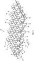
- FIG. 3 illustrates a fin pack 10 of one disclosed embodiment wherein the fin pack 10 is defined by offset strips or rows 12 of fins, in this configuration triangular fins 14.
- Fins 14 are defined by alternating upward and downward directed peaks 16, 18 that are connected along rows 12 by a central portion 20 which, in the illustrated configuration, can be a substantially horizontal portion defined between legs 22 of upward peaks 12 and legs 24 of downward peaks 18.
- Central portion 20 can define a center plane of the fin pack.
- Fins 14 define a flow direction corresponding to flow that will pass through fins 14 substantially transverse to rows 12, as illustrated by arrow A.
- a top-down view of a portion of fin pack 10 of FIG. 3 further illustrates features of central portion 20.
- central portions 20 also connect adjacent rows 12.
- central portion 20 is the only connection between adjacent rows 12 as this allows bending or flexing of one row 12 relative to the next row 12 at central portion 20, while offset peaks 16, 18 do not interfere with each other during such flexing or bending.
- gaps can be seen between rows 12. These gaps 12 can be provided in numerous ways, but can be lanced during stamping of the structure, in one embodiment, as will be further discussed below.
- fins 14 are described herein as having upward and downward peaks 16, 18. These directional orientations are taken with respect to a plane drawn through fin pack 10, specifically through a central plane defined by central portions 20, and considered when this plane is horizontal. It should of course be appreciated that in use, the peaks may be oriented differently, for example if fin pack 10 is incorporated into a heat exchanger to be mounted in an annular space of a gas turbine engine, then the central portions 20 and center plane of the fin pack might not be horizontal. Nevertheless, for purposes of disclosure, the upward and downward peaks 16, 18 should be considered with respect to a horizontal center plane of the fin pack.
- each upward peak 16 in one row 12 is adjacent to a downward peak 18 in an adjacent row 12.
- fin pack 10 can bend around an axis B that can be substantially transverse to the longitudinal direction of extent of rows 12, or that can be substantially parallel to the direction of flow. This greatly improves the conformability of fin pack 10 as disclosed herein, especially as compared to the configurations of FIGS. 1 and 2 .
- FIG. 5 is a side view along the flow direction A ( FIG. 3 ) to further illustrate details and configuration of peaks 16, 18, central portions 20 and legs 22, 24. As shown, central portions 20 connect adjacent rows 12 in the flow direction and also connect successive peaks 16, 18 in the direction of rows 12. Further, central portions define a lateral plane from which upward and downward peaks 16, 18 extend.
- FIG. 6 further illustrates a continuous connection region or central portion 20 between successive legs 22, 24 along row 12.
- This configuration can be advantageous for numerous reasons.
- this structure allows the fin pack to be conformable by allowing fin pack 10 to bend along the flow direction, that is, around an axis B ( FIG. 8 ) that is substantially parallel to rows 12 and substantially transverse to the flow direction.
- FIG. 7 illustrates how the disclosed configuration allows this flexibility.
- FIG. 7 illustrates a section through three adjacent rows 12a, 12b, 12c. Peaks 16 of rows 12a and 12c are offset from the peak 16 of row 12b, and instead peaks 16 are aligned with a space between offset peaks 16 (not visible in FIG. 7 ) of row 12b.
- fin pack 10 as disclosed herein is flexed around axis B, upward peaks 16 of rows 12a and 12c can bend into a gap between legs of an adjacent peak because the adjacent peak in row 12b is a downward peak 18.
- fin pack 10 as disclosed herein also allows complex curvature of the fin pack, including curving in portions that are in opposite directions, that is, some curving that is convex upwardly and some curving that is convex downwardly. This flexibility greatly enhances the ability for the fin pack as disclosed herein to be used in positions where conformability is needed.
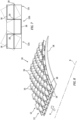
- FIG. 8 illustrates a conformable fin pack 10 curved around axis B, or along the flow direction.
- fin pack 10 is supported on a parting plate 28.
- Parting plates 28 can be used to complete fin pack 10 into a heat exchanger, closing off upper and lower surfaces of the intended flow area.
- FIG. 9 further illustrates a parting plate 28 which, in this configuration, has a series of grooves 30 sized to receive peaks 18 (or 16) of a fin pack 10.
- FIGS. 10 and 11 further illustrate grooves 30, which receive peaks 16, 18 and, in one configuration, can be brazed or otherwise joined such that peaks are firmly held in grooves, preferably mechanically and also through bonded material.
- the depth of grooves can be selected to provide as much support for the rounded peaks of the fin pack as desired.
- Shallow grooves for example about 0.001 (0.025 mm) inches in depth, can be useful as providing contact area to support and enhance bonding of a peak positioned in the groove.
- a deeper groove increases the contact area, but also requires more machining and can lead to the need for a parting plate of greater thickness that may not be desired.
- FIG. 12 illustrates an assembly process for assembling a heat exchanger 32 including a fin pack 10 as disclosed herein.
- fin pack 10 can be formed through a number of different processes.
- One process is to obtain a substantially flat sheet of material, and stamp the material to form the desired offset fins and also to separate adjacent rows except for central portions 20.
- stamping process is one desirable manner of making fin pack 10 but a person skilled in the art will readily recognize that other manufacturing techniques could be utilized to obtain the desire structure.
- Next fin pack 10 is positioned on a parting plate 28 with downward peaks 18 located in grooves 30.
- Side bars 34 can be positioned on parting plate 28 on either side of fin pack 10 to further define the desired flow direction along arrow A.
- Another parting plate 28 (a top parting plate) can then be positioned on top of fin pack 10 and side bars 34, with upward peaks 16 in grooves 30 of top parting plate 28.
- One particularly suitable manner of bonding includes Fast Assisted Sintering Technique (FAST) or Spark Plasma Sintering (SPS) technique.
- FAST Fast Assisted Sintering Technique
- SPS Spark Plasma Sintering
- a heat exchanger can be made with numerous layers that would be assembled as discussed with respect to FIG. 12 .
- all layers can be assembled and then brazed at the same time into a cube or box-shape.
- a single layer assembled and brazed as discussed above can then be rolled to obtain the desired curve. This is illustrated in FIGS. 13A-13C , where a flat heat exchanger 32 is the starting configuration, manufactured for example as discussed above. This flat assembly can then be passed through rollers to gradually introduce the desired curve to the assembly.
- FIG. 13B shows a curve of heat exchanger 32 after a first pass through rollers
- FIG. 13C shows a final curvature, after sufficient passes through the rollers.
- a 3-4 bar roller is suitable.
- successive layers can be produced with different amounts of curvature, for example as shown in FIG. 14 , where the bottom heat exchange layer is curved the most, and the top is curved the least.
- another fin structure 36 can be introduced between each of the conformable heat exchangers 32 to be stacked, for example to produce a cross-flow heat exchanger.
- These fin structures 36 could be any conventional folded fin pack, and would be arranged to carry the other fluid stream with which heat exchange is to be conducted.
- conventional fin structures Arranged in the orientation shown in FIG. 14 , conventional fin structures have sufficient flexibility in this direction to fit between the adjacent heat exchangers 32 and curve to the appropriate shape or configuration.
- the outer heat exchange layer or top layer of FIG. 14 may have a longer arc length as compared to the lower heat exchange layer(s) or heat exchangers 32.
- This can lead to increased pressure loss and reduced mass flow, but can be compensated by having different passage height for each layer, that is, the height of the inner or lower heat exchanger layer in FIG. 14 (H inner ) can be less than the height of the outer or upper heat exchanger layer (H outer ).
- the height of a layer is defined as the space between the parting plates of the layer.
- the height of a radially inner layer, or H inner would in one non-limiting configuration be less than the height of a radially outer layer, or H outer , for example as shown in FIG. 14 .
- the fin pack 10 as disclosed herein has been referred to as having triangular fins. This refers to the shape of the fins wherein each peak is defined where two legs meet, at a rounded peak. It should be appreciated that the fins as disclosed herein do not need to be strictly triangular, but this is one configuration of particular interest. Further, and as discussed above, legs defining successive peaks along a row are separated by lateral or horizontal central portions 20 (see FIG. 6 ), and this can be advantageous as offset upper and lower leg segments can help to offset or accommodate thermal expansion. Further, with the shape of fins as disclosed herein, pressure loading is concentrated at the central portion, and the rounded interface of the peaks within grooves helps to prevent buckling during bonding.
- each defined fin can be rounded peaks, and in one non-limiting configuration, each rounded peak can have an inner radius (IR) which can be greater than or equal to one-half of a thickness of the material from which the rounded peaks are formed.
- IR inner radius
- the legs of the fins of fin pack 10 can be angled for wider or narrower spacing, and this spacing can help to provide fin pack 10 with desired properties to handle or respond to stress during assembly, bonding and use.
- the legs can be angled relative to the horizontal plane in which connection portions 20 are defined, at an angle between 50 and 80 degrees, or between 60 and 70 degrees, and angles of 60 or 70 degrees are particularly suitable.
- the heating and cooling to which heat exchanger 32 is exposed will induce stress into the component, for example at central portion 20. This may ultimately lead to portions of the fin pack to break, but the fin pack will nevertheless remain bonded to the parting plates and side bars.
Landscapes
- Engineering & Computer Science (AREA)
- Physics & Mathematics (AREA)
- Thermal Sciences (AREA)
- Mechanical Engineering (AREA)
- General Engineering & Computer Science (AREA)
- Heat-Exchange Devices With Radiators And Conduit Assemblies (AREA)
Abstract
Description
- This disclosure relates to heat exchangers and, more particularly, to a conformal heat exchanger having triangular offset strip fins that allow the heat exchanger to bend along the flow direction of the fin pack.
- Heat exchangers typically have a structure as shown in
FIG. 1 , also further discussed below, wherein the heat exchanger is a stack of rigid components, for example, to define hot side and cold side flows, and are brazed together to form a monolithic cube. This leads to a rectangular, or box-shaped, non-conformal geometry. This type of heat exchanger is effective in heat exchange with one or more fluids, but can be difficult to accommodate in spaces that are not well suited to a box-shaped article. - Numerous applications of heat exchangers do not have a convenient box-shaped space to accept a heat exchanger. As one example, gas turbine engines use heat exchangers, and the spaces available are frequently annular or at least round in shape. Known box-shaped heat exchangers can be difficult to utilize in such spaces.
- The present disclosure relates to a conformable or conformal heat exchanger which can be bent or curved along a length of the flow passages defined in the heat exchanger.
- In one non-limiting embodiment, a fin pack for a conformal heat exchanger, comprises alternating rows of fins defined in a lateral plane, each row of fins comprising alternating upward and downward extending peaks extending upwardly and downwardly from the lateral plane, wherein adjacent rows of fins are connected by central portions in the lateral plane, and wherein upward and downward extending peaks of adjacent rows are offset from each other along the rows.
- In a further non-limiting configuration, each upward extending peak of one row is laterally aligned with a downward extending peak of an adjacent row.
- In a still further non-limiting configuration, the upward and downward extending peaks comprise legs extending between the lateral plane and the peak, and the central portions comprise horizontal connecting portions defined in the plane, wherein the horizontal connecting portions connect legs of alternating upward and downward extending peaks along each row, and the horizontal connecting portions also connect to horizontal connecting portions of each adjacent row.
- In another non-limiting configuration, the legs are arranged at an angle with respect to the lateral plane of between 50 and 80 degrees.
- In still another non-limiting configuration, the angle is between 60 and 70 degrees.
- In a further non-limiting configuration, the fin pack is defined from sheet metal such that the central portions are contiguous sheet metal material with the adjacent rows.
- In a still further non-limiting configuration, each peak terminates in a rounded peak.
- In another non-limiting configuration, the rounded peak is defined in a material having a thickness, and an inner radius of the rounded peak (IR) is greater than one-half the thickness of the material.
- In still another non-limiting configuration, the fin pack is flexible at the central portions and, when bending at the central portions, an upward extending peak of one row extends into a space created by a downward extending peak of the adjacent row.
- In a further non-limiting embodiment, a conformal heat exchanger comprises the fin pack as disclosed herein; and at least one parting plate arranged along the fin pack in contact with at least one of the upward and the downward extending peaks.
- In another non-limiting configuration, the fin pack is bonded to the at least one parting plate at the upward and downward extending peaks.
- In still another non-limiting configuration, the at least one parting plate comprises grooves arranged to receive peaks of the fin pack.
- In a further non-limiting configuration, the peaks of the fin pack are bonded to the at least one parting plate in the grooves.
- In another non-limiting configuration, the heat exchanger further comprises side bars arranged along ends of the rows to define heat exchange flow paths along the upward and downward extending peaks.
- In still another non-limiting configuration, the at least one parting plate and the fin pack are curved around an axis extending parallel to the rows.
- In a further non-limiting embodiment, a method for making a conformable heat exchanger, comprises die stamping a sheet of metal to produce a fin pack comprising alternating rows of fins defined in a lateral plane, each row of fins comprising alternating upward and downward extending peaks extending upwardly and downwardly from the lateral plane, wherein adjacent rows of fins are connected by central portions in the lateral plane, and wherein upward and downward extending peaks of adjacent rows are offset from each other along the rows; positioning the fin pack between a first parting plate in contact with the downward extending peaks and a second parting plate in contact with the upward extending peaks; and bonding the upward and downward extending peaks to the first parting plate and the second parting plate to define the conformable heat exchanger.
- In a non-limiting configuration, the method further comprises bending the conformable heat exchanger around an axis parallel to the rows of the fin pack.
- In a further non-limiting configuration, the first parting plate and the second parting plate comprise grooves arranged to receive peaks of the fin pack, wherein the positioning step positions the peaks in the grooves, and wherein the bonding step bonds the peaks in the grooves.
- In a still further non-limiting configuration, the method further comprises positioning side bars along non-flow edges of the fin pack between the first parting plate and the second parting plate, and wherein the bonding step also bonds the side bars to the first parting plate and the second parting plate.
- In another non-limiting configuration, the method further comprises making a plurality of conformable heat exchangers and bending the plurality of conformable heat exchangers to produce a plurality of curved conformable heat exchangers, and stacking the plurality of curved conformable heat exchangers to produce a final multi-layer curved conformable heat exchanger wherein each layer has a height measured as distance between the first parting plate and the second parting plate, and wherein the plurality of curved conformable heat exchangers have different heights with respect to each other.
- The foregoing features and elements may be combined in various combinations without exclusivity, unless expressly indicated otherwise. These features and elements, as well as the operation thereof, will become more apparent in light of the following description and the accompanying drawings. It should be appreciated that the following description and drawings are intended to be exemplary in nature and non-limiting.
- A detailed description of non-limiting embodiments of the present disclosure follows, with reference to the attached drawings, wherein:
-
FIG. 1 illustrates a conventional box-shaped heat exchanger; -
FIG. 2 illustrates a conventional offset fin configuration; -
FIG. 3 illustrates a conformal triangular offset strip fin pack as disclosed herein; -
FIG. 4 is a top view of a portion ofFIG. 3 ; -
FIG. 5 is a side view of a portion of two adjacent rows; -
FIG. 6 is a side view of a central or connecting portion as disclosed herein; -
FIG. 7 illustrates how a conformable fin pack as disclosed herein can flex along a row. -
FIG. 8 further illustrates a fin pack as disclosed herein, in this configuration formed around a curved configuration; -
FIG. 9 illustrates a parting plate with grooves for accommodating peaks of a fin pack; -
FIGS. 10 and 11 present an enlarged view of a groove (FIG. 10 ) with a downward peak (FIG. 11 ) held within the groove. -
FIG. 12 illustrates assembly of a heat exchanger as disclosed herein; -
FIGS. 13A-13C illustrates steps of bending a conformable heat exchanger as disclosed herein; and -
FIG. 14 illustrates stacked conformal heat exchangers. - The disclosure relates to non-conformal triangular offset strip fin heat exchangers.
-
FIG. 1 shows, in a partially exploded view, aconventional heat exchanger 1 wherein corrugatedfins flat plates 4 or brazing sheets, withside bars 5 to seal flows from one another. The partially exploded assembly ofFIG. 1 is brazed into a box-shaped heat exchanger 1. Such a heat exchanger is rigid and not conformal, and therefore is difficult to incorporate into some spaces. -
FIG. 2 illustrates a conventionalstrip fin configuration 6 whereinrows 7 offins 8 are stamped into sheet metal. The fins in adjacent rows are offset from each other, and have substantially flat tops and bottoms as shown. Further, adjacent rows are still connected to each other at top andbottom portions 9. While effective at heat exchange in the proper situation, this type of fin structure or fin pack still has no flexibility or ability to bend around an axis parallel torows 7. -
FIG. 3 illustrates afin pack 10 of one disclosed embodiment wherein thefin pack 10 is defined by offset strips orrows 12 of fins, in this configurationtriangular fins 14. Fins 14 are defined by alternating upward and downward directedpeaks rows 12 by acentral portion 20 which, in the illustrated configuration, can be a substantially horizontal portion defined betweenlegs 22 ofupward peaks 12 andlegs 24 of downwardpeaks 18.Central portion 20 can define a center plane of the fin pack. Fins 14 define a flow direction corresponding to flow that will pass throughfins 14 substantially transverse torows 12, as illustrated by arrow A. - Referring also to
FIG. 4 , a top-down view of a portion offin pack 10 ofFIG. 3 further illustrates features ofcentral portion 20. In addition to connectingsuccessive peaks row 12,central portions 20 also connectadjacent rows 12. Further, in one non-limiting configuration,central portion 20 is the only connection betweenadjacent rows 12 as this allows bending or flexing of onerow 12 relative to thenext row 12 atcentral portion 20, whileoffset peaks FIG. 4 , gaps can be seen betweenrows 12. Thesegaps 12 can be provided in numerous ways, but can be lanced during stamping of the structure, in one embodiment, as will be further discussed below. - It is noted that
fins 14 are described herein as having upward anddownward peaks fin pack 10, specifically through a central plane defined bycentral portions 20, and considered when this plane is horizontal. It should of course be appreciated that in use, the peaks may be oriented differently, for example iffin pack 10 is incorporated into a heat exchanger to be mounted in an annular space of a gas turbine engine, then thecentral portions 20 and center plane of the fin pack might not be horizontal. Nevertheless, for purposes of disclosure, the upward anddownward peaks - As also can be seen in both
FIGS. 3 and4 , inadjacent rows 12, upward peaks 16 and downward peaks 18 are offset from each other. Specifically, the offset is alongrow 12 such that anupward peak 16 is not adjacent to another upward peak in the adjacent row. In the illustrated configuration, eachupward peak 16 in onerow 12 is adjacent to adownward peak 18 in anadjacent row 12. As will be further discussed below, configuring adjacent rows to be connected only bycentral portions 20, with upward anddownward peaks fin pack 10 can bend around an axis B that can be substantially transverse to the longitudinal direction of extent ofrows 12, or that can be substantially parallel to the direction of flow. This greatly improves the conformability offin pack 10 as disclosed herein, especially as compared to the configurations ofFIGS. 1 and 2 . -
FIG. 5 is a side view along the flow direction A (FIG. 3 ) to further illustrate details and configuration ofpeaks central portions 20 andlegs central portions 20 connectadjacent rows 12 in the flow direction and also connectsuccessive peaks rows 12. Further, central portions define a lateral plane from which upward anddownward peaks -
FIG. 6 further illustrates a continuous connection region orcentral portion 20 betweensuccessive legs row 12. This configuration can be advantageous for numerous reasons. First, this structure allows the fin pack to be conformable by allowingfin pack 10 to bend along the flow direction, that is, around an axis B (FIG. 8 ) that is substantially parallel torows 12 and substantially transverse to the flow direction. -
FIG. 7 illustrates how the disclosed configuration allows this flexibility.FIG. 7 illustrates a section through threeadjacent rows Peaks 16 ofrows peak 16 ofrow 12b, and instead peaks 16 are aligned with a space between offset peaks 16 (not visible inFIG. 7 ) ofrow 12b. Whenfin pack 10 as disclosed herein is flexed around axis B, upward peaks 16 ofrows row 12b is adownward peak 18. This is schematically illustrated by the broken line position shown forupward peaks 16 on the left and right side of the figure, bending into open space created by virtue of the fact that the adjacent upward peaks are on either side of adownward peak 18. During such bending,fin pack 10 bends atcentral portion 20. It should be noted that the broken line position ofpeaks 16 shown inFIG. 7 would correspond to bending offin pack 10 upwardly. In a configuration where fin pack is to bend downwardly,adjacent rows 12 would pivot in the opposite direction, withpeak 18 ofrow 12b occupying space between peaks 18 (not visible inFIG. 7 ) ofrows FIG. 8 discussed below. Also, it should be appreciated that while this discussion is in terms of a simple curvature offin pack 10, for example a single radius of curvature as shown inFIG. 8 ,fin pack 10 as disclosed herein also allows complex curvature of the fin pack, including curving in portions that are in opposite directions, that is, some curving that is convex upwardly and some curving that is convex downwardly. This flexibility greatly enhances the ability for the fin pack as disclosed herein to be used in positions where conformability is needed. -
FIG. 8 illustrates aconformable fin pack 10 curved around axis B, or along the flow direction. In this illustration,fin pack 10 is supported on aparting plate 28. Partingplates 28 can be used to completefin pack 10 into a heat exchanger, closing off upper and lower surfaces of the intended flow area. -
FIG. 9 further illustrates aparting plate 28 which, in this configuration, has a series ofgrooves 30 sized to receive peaks 18 (or 16) of afin pack 10.FIGS. 10 and 11 further illustrategrooves 30, which receive peaks 16, 18 and, in one configuration, can be brazed or otherwise joined such that peaks are firmly held in grooves, preferably mechanically and also through bonded material. - The depth of grooves can be selected to provide as much support for the rounded peaks of the fin pack as desired. Shallow grooves, for example about 0.001 (0.025 mm) inches in depth, can be useful as providing contact area to support and enhance bonding of a peak positioned in the groove. A deeper groove increases the contact area, but also requires more machining and can lead to the need for a parting plate of greater thickness that may not be desired.
-
FIG. 12 illustrates an assembly process for assembling aheat exchanger 32 including afin pack 10 as disclosed herein. - First,
fin pack 10 can be formed through a number of different processes. One process, however, is to obtain a substantially flat sheet of material, and stamp the material to form the desired offset fins and also to separate adjacent rows except forcentral portions 20. Such a stamping process is one desirable manner of makingfin pack 10 but a person skilled in the art will readily recognize that other manufacturing techniques could be utilized to obtain the desire structure. -
Next fin pack 10 is positioned on aparting plate 28 withdownward peaks 18 located ingrooves 30. Side bars 34 can be positioned on partingplate 28 on either side offin pack 10 to further define the desired flow direction along arrow A. - Another parting plate 28 (a top parting plate) can then be positioned on top of
fin pack 10 and side bars 34, withupward peaks 16 ingrooves 30 oftop parting plate 28. - Once the components are assembled as described, the components can then be brazed together. One particularly suitable manner of bonding includes Fast Assisted Sintering Technique (FAST) or Spark Plasma Sintering (SPS) technique.
- It should be appreciated that a heat exchanger can be made with numerous layers that would be assembled as discussed with respect to
FIG. 12 . When it is not needed for the heat exchanger to be conformable, then all layers can be assembled and then brazed at the same time into a cube or box-shape. However, when it is desired for theheat exchanger 32 to be conformable, then a single layer assembled and brazed as discussed above can then be rolled to obtain the desired curve. This is illustrated inFIGS. 13A-13C , where aflat heat exchanger 32 is the starting configuration, manufactured for example as discussed above. This flat assembly can then be passed through rollers to gradually introduce the desired curve to the assembly. -
FIG. 13B shows a curve ofheat exchanger 32 after a first pass through rollers, andFIG. 13C shows a final curvature, after sufficient passes through the rollers. For this purpose, in one non-limiting configuration, a 3-4 bar roller is suitable. - When a stacked conformable heat exchanger is desired, successive layers can be produced with different amounts of curvature, for example as shown in
FIG. 14 , where the bottom heat exchange layer is curved the most, and the top is curved the least. As shown inFIG. 14 , anotherfin structure 36 can be introduced between each of theconformable heat exchangers 32 to be stacked, for example to produce a cross-flow heat exchanger. Thesefin structures 36 could be any conventional folded fin pack, and would be arranged to carry the other fluid stream with which heat exchange is to be conducted. Arranged in the orientation shown inFIG. 14 , conventional fin structures have sufficient flexibility in this direction to fit between theadjacent heat exchangers 32 and curve to the appropriate shape or configuration. - In this configuration, the outer heat exchange layer or top layer of
FIG. 14 may have a longer arc length as compared to the lower heat exchange layer(s) orheat exchangers 32. This can lead to increased pressure loss and reduced mass flow, but can be compensated by having different passage height for each layer, that is, the height of the inner or lower heat exchanger layer inFIG. 14 (Hinner) can be less than the height of the outer or upper heat exchanger layer (Houter). In this regard, it should be appreciated that the height of a layer is defined as the space between the parting plates of the layer. Withheat exchangers 32 being conformable and, for example, being combined into a curved structure as is illustrated inFIG. 14 , and with the different layers of a stacked structure having a different height, this serves to balance the mass flow through the layers and avoid the problems that might otherwise be caused by an imbalanced mass flow. - It should be appreciated that when prepared with layers of different height, the height of a radially inner layer, or Hinner, would in one non-limiting configuration be less than the height of a radially outer layer, or Houter, for example as shown in
FIG. 14 . - The
fin pack 10 as disclosed herein has been referred to as having triangular fins. This refers to the shape of the fins wherein each peak is defined where two legs meet, at a rounded peak. It should be appreciated that the fins as disclosed herein do not need to be strictly triangular, but this is one configuration of particular interest. Further, and as discussed above, legs defining successive peaks along a row are separated by lateral or horizontal central portions 20 (seeFIG. 6 ), and this can be advantageous as offset upper and lower leg segments can help to offset or accommodate thermal expansion. Further, with the shape of fins as disclosed herein, pressure loading is concentrated at the central portion, and the rounded interface of the peaks within grooves helps to prevent buckling during bonding. - As mentioned herein, the peaks of each defined fin can be rounded peaks, and in one non-limiting configuration, each rounded peak can have an inner radius (IR) which can be greater than or equal to one-half of a thickness of the material from which the rounded peaks are formed.
- The legs of the fins of
fin pack 10 can be angled for wider or narrower spacing, and this spacing can help to providefin pack 10 with desired properties to handle or respond to stress during assembly, bonding and use. In one non-limiting configuration, the legs can be angled relative to the horizontal plane in whichconnection portions 20 are defined, at an angle between 50 and 80 degrees, or between 60 and 70 degrees, and angles of 60 or 70 degrees are particularly suitable. - During use, the heating and cooling to which
heat exchanger 32 is exposed will induce stress into the component, for example atcentral portion 20. This may ultimately lead to portions of the fin pack to break, but the fin pack will nevertheless remain bonded to the parting plates and side bars. - It should be appreciated that a conformable fin pack and heat exchanger have been disclosed herein which allow a heat exchanger to be used in conformable manner to fit available areas that do not readily accept a box-shaped heat exchanger, thereby helping to put better use to available space, for example in the context of a gas turbine engine.
- The foregoing description is exemplary of the subject matter of the invention disclosed herein. Various non-limiting embodiments are disclosed, however, one of ordinary skill in the art would recognize that various modifications and variations in light of the above teachings will fall within the scope of the appended claims. It is therefore to be appreciated that within the scope of the appended claims, the disclosure may be practiced other than as specifically described. Thus, the scope of the present claims is not specifically limited by the details of specific embodiment disclosed herein, but rather the claims define the full and reasonable scope of the invention.
Claims (15)
- A fin pack (10) for a conformal heat exchanger (32), comprising:
alternating rows (12) of fins (14) defined in a lateral plane, each row (12) of fins (14) comprising alternating upward and downward extending peaks (16, 18) extending upwardly and downwardly from the lateral plane, wherein adjacent rows (12) of fins (14) are connected by central portions (20) in the lateral plane, and wherein upward and downward extending peaks (16, 18) of adjacent rows (12) are offset from each other along the rows (12). - The fin pack (10) of claim 1, wherein each upward extending peak (16) of one row (12) is laterally aligned with a downward extending peak (18) of an adjacent row (12).
- The fin pack (10) of claim 1 or 2, wherein the upward and downward extending peaks (16, 18) comprise legs (22, 24) extending between the lateral plane and the peak (16, 18), and wherein the central portions (20) comprise horizontal connecting portions defined in the plane, wherein the horizontal connecting portions connect legs (22, 24) of alternating upward and downward extending peaks (16, 18) along each row (12), and the horizontal connecting portions also connect to horizontal connecting portions of each adjacent row (12),wherein, optionally, the legs (22, 24) are arranged at an angle with respect to the lateral plane of between 50 and 80 degrees,wherein, further optionally, the angle is between 60 and 70 degrees.
- The fin pack (10) of claim 1, 2 or 3, wherein the fin pack (10) is defined from sheet metal such that the central portions (20) are contiguous sheet metal material with the adjacent rows (12).
- The fin pack (10) of any preceding claim, wherein each peak (16, 18) terminates in a rounded peak,
wherein, optionally, the rounded peak is defined in a material having a thickness, and wherein an inner radius of the rounded peak (IR) is greater than one-half the thickness of the material. - The fin pack (10) of any preceding claim, wherein the fin pack (10) is flexible at the central portions (20) and, when bending at the central portions (20), an upward extending peak (16) of one row (12) extends into a space created by a downward extending peak (18) of the adjacent row (12).
- A conformal heat exchanger (32), comprising:the fin pack (10) of any preceding claim; andat least one parting plate (28) arranged along the fin pack (10) in contact with at least one of the upward and the downward extending peaks (16, 18).
- The heat exchanger (32) of claim 7, wherein:the fin pack (10) is bonded to the at least one parting plate (28) at the upward and downward extending peaks (16, 18); and/orthe at least one parting plate (28) comprises grooves (30) arranged to receive peaks (16, 18) of the fin pack (10), wherein, optionally, the peaks (16, 18) of the fin pack (10) are bonded to the at least one parting plate (28) in the grooves (30).
- The heat exchanger (32) of claim 7 or 8, further comprising side bars (34) arranged along ends of the rows (12) to define heat exchange flow paths along the upward and downward extending peaks (16, 18).
- The heat exchanger (32) of claim 7, 8 or 9, wherein the at least one parting plate (28) and the fin pack (10) are curved around an axis extending parallel to the rows (12).
- A method for making a conformable heat exchanger (32), comprising:die stamping a sheet of metal to produce a fin pack (10) comprising alternating rows (12) of fins (14) defined in a lateral plane, each row (12) of fins (14) comprising alternating upward and downward extending peaks (16, 18) extending upwardly and downwardly from the lateral plane, wherein adjacent rows (12) of fins (14) are connected by central portions (20) in the lateral plane, and wherein upward and downward extending peaks (16, 18) of adjacent rows (12) are offset from each other along the rows (12);positioning the fin pack (10) between a first parting plate (28) in contact with the downward extending peaks (18) and a second parting plate (28) in contact with the upward extending peaks (16); andbonding the upward and downward extending peaks (16, 18) to the first parting plate (28) and the second parting plate (28) to define the conformable heat exchanger (32).
- The method of claim 11, further comprising bending the conformable heat exchanger (32) around an axis parallel to the rows (12) of the fin pack (10).
- The method of claim 11 or 12, wherein the first parting plate (28) and the second parting plate (28) comprise grooves (30) arranged to receive peaks (16, 18) of the fin pack (10), wherein the positioning step positions the peaks (16, 18) in the grooves (30), and wherein the bonding step bonds the peaks (16, 18) in the grooves (30).
- The method of claim 11, 12 or 13, further comprising positioning side bars (34) along non-flow edges of the fin pack (10) between the first parting plate (28) and the second parting plate (28), and wherein the bonding step also bonds the side bars (34) to the first parting plate (28) and the second parting plate (28).
- The method of any of claims 11 to 14, further comprising making a plurality of conformable heat exchangers (32) and bending the plurality of conformable heat exchangers (32) to produce a plurality of curved conformable heat exchangers (32), and stacking the plurality of curved conformable heat exchangers (32) to produce a final multi-layer curved conformable heat exchanger (32) wherein each layer has a height measured as distance between the first parting plate (28) and the second parting plate (28), and wherein the plurality of curved conformable heat exchangers (32) have different heights with respect to each other.
Applications Claiming Priority (1)
| Application Number | Priority Date | Filing Date | Title |
|---|---|---|---|
| US18/106,064 US20240263884A1 (en) | 2023-02-06 | 2023-02-06 | Conformal heat exchanger with triangular offset strip fins |
Publications (2)
| Publication Number | Publication Date |
|---|---|
| EP4411301A1 true EP4411301A1 (en) | 2024-08-07 |
| EP4411301B1 EP4411301B1 (en) | 2026-04-01 |
Family
ID=89853451
Family Applications (1)
| Application Number | Title | Priority Date | Filing Date |
|---|---|---|---|
| EP24156020.0A Active EP4411301B1 (en) | 2023-02-06 | 2024-02-06 | Conformal heat exchanger with triangular offset strip fins |
Country Status (2)
| Country | Link |
|---|---|
| US (1) | US20240263884A1 (en) |
| EP (1) | EP4411301B1 (en) |
Families Citing this family (1)
| Publication number | Priority date | Publication date | Assignee | Title |
|---|---|---|---|---|
| US12298080B2 (en) * | 2022-02-10 | 2025-05-13 | Rtx Corporation | Conformal heat exchanger |
Citations (5)
| Publication number | Priority date | Publication date | Assignee | Title |
|---|---|---|---|---|
| US6546774B2 (en) * | 2001-08-23 | 2003-04-15 | Modine Manufacturing Company | Method of making a lanced and offset fin |
| DE202008013351U1 (en) * | 2008-10-08 | 2010-03-25 | Autokühler GmbH & Co. KG | Heat exchanger network and thus equipped heat exchanger |
| US20190086160A1 (en) * | 2015-07-29 | 2019-03-21 | Danfoss Micro Channel Heat Exchanger (Jiaxing) Co. | Fin assembly for heat exchanger and heat exchanger having the fin assembly |
| US10392952B2 (en) * | 2016-04-01 | 2019-08-27 | Safran Aircraft Engines | Output director vane for an aircraft turbine engine, with an improved lubricant cooling function using a heat conduction matrix housed in an inner duct of the vane |
| US20200370834A1 (en) * | 2017-11-27 | 2020-11-26 | Dana Canada Corporation | Enhanced heat transfer surface |
Family Cites Families (10)
| Publication number | Priority date | Publication date | Assignee | Title |
|---|---|---|---|---|
| US3732921A (en) * | 1971-06-30 | 1973-05-15 | Modine Mfg Co | Heat exchanger |
| DE3049168C2 (en) * | 1980-12-24 | 1987-03-19 | Dieter Christian Steinegg-Appenzell Steeb | Method for producing a heat exchanger with bent flat tubes |
| JPS61262593A (en) * | 1985-05-15 | 1986-11-20 | Showa Alum Corp | Heat exchanger |
| US5107922A (en) * | 1991-03-01 | 1992-04-28 | Long Manufacturing Ltd. | Optimized offset strip fin for use in contact heat exchangers |
| US6273183B1 (en) * | 1997-08-29 | 2001-08-14 | Long Manufacturing Ltd. | Heat exchanger turbulizers with interrupted convolutions |
| JPH11311488A (en) * | 1998-04-28 | 1999-11-09 | Nippon Light Metal Co Ltd | Heat exchanger |
| US6213158B1 (en) * | 1999-07-01 | 2001-04-10 | Visteon Global Technologies, Inc. | Flat turbulator for a tube and method of making same |
| JP4231610B2 (en) * | 2000-02-09 | 2009-03-04 | サンデン株式会社 | Manufacturing method of heat exchanger fins |
| JP4587707B2 (en) * | 2004-02-19 | 2010-11-24 | カルソニックカンセイ株式会社 | Corrugated fin manufacturing apparatus and corrugated fin manufacturing method |
| FR3040478B1 (en) * | 2015-08-25 | 2017-12-15 | Valeo Systemes Thermiques | HEAT EXCHANGER |
-
2023
- 2023-02-06 US US18/106,064 patent/US20240263884A1/en active Pending
-
2024
- 2024-02-06 EP EP24156020.0A patent/EP4411301B1/en active Active
Patent Citations (5)
| Publication number | Priority date | Publication date | Assignee | Title |
|---|---|---|---|---|
| US6546774B2 (en) * | 2001-08-23 | 2003-04-15 | Modine Manufacturing Company | Method of making a lanced and offset fin |
| DE202008013351U1 (en) * | 2008-10-08 | 2010-03-25 | Autokühler GmbH & Co. KG | Heat exchanger network and thus equipped heat exchanger |
| US20190086160A1 (en) * | 2015-07-29 | 2019-03-21 | Danfoss Micro Channel Heat Exchanger (Jiaxing) Co. | Fin assembly for heat exchanger and heat exchanger having the fin assembly |
| US10392952B2 (en) * | 2016-04-01 | 2019-08-27 | Safran Aircraft Engines | Output director vane for an aircraft turbine engine, with an improved lubricant cooling function using a heat conduction matrix housed in an inner duct of the vane |
| US20200370834A1 (en) * | 2017-11-27 | 2020-11-26 | Dana Canada Corporation | Enhanced heat transfer surface |
Also Published As
| Publication number | Publication date |
|---|---|
| US20240263884A1 (en) | 2024-08-08 |
| EP4411301B1 (en) | 2026-04-01 |
Similar Documents
| Publication | Publication Date | Title |
|---|---|---|
| EP3633300B1 (en) | Plate-fin heat exchanger core design for improved manufacturing | |
| EP2126506B1 (en) | Plate heat exchanger | |
| JP6126358B2 (en) | Multi-plate oil cooler | |
| CN102695936A (en) | Stacked/bar plate charge air cooler including inlet and outlet tanks | |
| JP5733900B2 (en) | Manufacturing method of plate heat exchanger and plate heat exchanger | |
| JP7568304B2 (en) | Heat transport device and method for manufacturing same | |
| EP2942593B1 (en) | Multi-plate-stack-type heat exchanger, and core plate therefor | |
| EP4411301A1 (en) | Conformal heat exchanger with triangular offset strip fins | |
| JP2010121928A (en) | Heat exchanger and method for manufacturing the same | |
| EP3301393B1 (en) | Heat exchanger | |
| CA1069883A (en) | Compact primary surface heat exchanger | |
| US20190247942A1 (en) | Method for producing a plate heat exchanger block with targeted application of the solder material to fins and sidebars in particular | |
| JP2019020091A (en) | Heat exchanger manufacturing method, heat exchanger overlapping method, heat exchanger, and multi-row heat exchanger | |
| JP2013127341A (en) | Heat exchanger | |
| JP6435487B2 (en) | Heat exchanger | |
| JP5140803B2 (en) | Heat exchanger and manufacturing method thereof | |
| RU2659677C1 (en) | Plate heat exchanger and the plate heat exchanger manufacturing method | |
| WO2022107868A1 (en) | Heat exchanger | |
| JP7021925B2 (en) | Heat exchanger | |
| CN110906776A (en) | Heat exchanger and method for manufacturing same | |
| EP4198435A1 (en) | Heat exchanger with partial-height folded fins | |
| JP2002250596A (en) | Method for manufacturing stacked heat exchanger | |
| JP2019184166A (en) | Heat exchanger | |
| JP2026060456A (en) | heat exchanger | |
| JP2004125196A (en) | Heat exchanger for water heater |
Legal Events
| Date | Code | Title | Description |
|---|---|---|---|
| PUAI | Public reference made under article 153(3) epc to a published international application that has entered the european phase |
Free format text: ORIGINAL CODE: 0009012 |
|
| STAA | Information on the status of an ep patent application or granted ep patent |
Free format text: STATUS: THE APPLICATION HAS BEEN PUBLISHED |
|
| AK | Designated contracting states |
Kind code of ref document: A1 Designated state(s): AL AT BE BG CH CY CZ DE DK EE ES FI FR GB GR HR HU IE IS IT LI LT LU LV MC ME MK MT NL NO PL PT RO RS SE SI SK SM TR |
|
| STAA | Information on the status of an ep patent application or granted ep patent |
Free format text: STATUS: REQUEST FOR EXAMINATION WAS MADE |
|
| 17P | Request for examination filed |
Effective date: 20250207 |
|
| GRAP | Despatch of communication of intention to grant a patent |
Free format text: ORIGINAL CODE: EPIDOSNIGR1 |
|
| STAA | Information on the status of an ep patent application or granted ep patent |
Free format text: STATUS: GRANT OF PATENT IS INTENDED |
|
| INTG | Intention to grant announced |
Effective date: 20251002 |
|
| GRAS | Grant fee paid |
Free format text: ORIGINAL CODE: EPIDOSNIGR3 |
|
| GRAA | (expected) grant |
Free format text: ORIGINAL CODE: 0009210 |
|
| STAA | Information on the status of an ep patent application or granted ep patent |
Free format text: STATUS: THE PATENT HAS BEEN GRANTED |
|
| AK | Designated contracting states |
Kind code of ref document: B1 Designated state(s): AL AT BE BG CH CY CZ DE DK EE ES FI FR GB GR HR HU IE IS IT LI LT LU LV MC ME MK MT NL NO PL PT RO RS SE SI SK SM TR |
|
| REG | Reference to a national code |
Ref country code: CH Ref legal event code: F10 Free format text: ST27 STATUS EVENT CODE: U-0-0-F10-F00 (AS PROVIDED BY THE NATIONAL OFFICE) Effective date: 20260401 Ref country code: GB Ref legal event code: FG4D |
|
| REG | Reference to a national code |
Ref country code: IE Ref legal event code: FG4D |
|
| REG | Reference to a national code |
Ref country code: DE Ref legal event code: R096 Ref document number: 602024003505 Country of ref document: DE |