EP4411288A1 - Air conditioner - Google Patents
Air conditioner Download PDFInfo
- Publication number
- EP4411288A1 EP4411288A1 EP22875456.0A EP22875456A EP4411288A1 EP 4411288 A1 EP4411288 A1 EP 4411288A1 EP 22875456 A EP22875456 A EP 22875456A EP 4411288 A1 EP4411288 A1 EP 4411288A1
- Authority
- EP
- European Patent Office
- Prior art keywords
- refrigerant
- pipe
- component
- refrigerant pipe
- metal pipe
- Prior art date
- Legal status (The legal status is an assumption and is not a legal conclusion. Google has not performed a legal analysis and makes no representation as to the accuracy of the status listed.)
- Granted
Links
Images




Classifications
-
- F—MECHANICAL ENGINEERING; LIGHTING; HEATING; WEAPONS; BLASTING
- F25—REFRIGERATION OR COOLING; COMBINED HEATING AND REFRIGERATION SYSTEMS; HEAT PUMP SYSTEMS; MANUFACTURE OR STORAGE OF ICE; LIQUEFACTION SOLIDIFICATION OF GASES
- F25B—REFRIGERATION MACHINES, PLANTS OR SYSTEMS; COMBINED HEATING AND REFRIGERATION SYSTEMS; HEAT PUMP SYSTEMS
- F25B41/00—Fluid-circulation arrangements
- F25B41/40—Fluid line arrangements
-
- F—MECHANICAL ENGINEERING; LIGHTING; HEATING; WEAPONS; BLASTING
- F24—HEATING; RANGES; VENTILATING
- F24F—AIR-CONDITIONING; AIR-HUMIDIFICATION; VENTILATION; USE OF AIR CURRENTS FOR SCREENING
- F24F1/00—Room units for air-conditioning, e.g. separate or self-contained units or units receiving primary air from a central station
- F24F1/06—Separate outdoor units, e.g. outdoor unit to be linked to a separate room comprising a compressor and a heat exchanger
- F24F1/26—Refrigerant piping
-
- F—MECHANICAL ENGINEERING; LIGHTING; HEATING; WEAPONS; BLASTING
- F25—REFRIGERATION OR COOLING; COMBINED HEATING AND REFRIGERATION SYSTEMS; HEAT PUMP SYSTEMS; MANUFACTURE OR STORAGE OF ICE; LIQUEFACTION SOLIDIFICATION OF GASES
- F25B—REFRIGERATION MACHINES, PLANTS OR SYSTEMS; COMBINED HEATING AND REFRIGERATION SYSTEMS; HEAT PUMP SYSTEMS
- F25B47/00—Arrangements for preventing or removing deposits or corrosion, not provided for in another subclass
- F25B47/003—Arrangements for preventing or removing deposits or corrosion, not provided for in another subclass for preventing corrosion
-
- F—MECHANICAL ENGINEERING; LIGHTING; HEATING; WEAPONS; BLASTING
- F28—HEAT EXCHANGE IN GENERAL
- F28D—HEAT-EXCHANGE APPARATUS, NOT PROVIDED FOR IN ANOTHER SUBCLASS, IN WHICH THE HEAT-EXCHANGE MEDIA DO NOT COME INTO DIRECT CONTACT
- F28D1/00—Heat-exchange apparatus having stationary conduit assemblies for one heat-exchange medium only, the media being in contact with different sides of the conduit wall, in which the other heat-exchange medium is a large body of fluid, e.g. domestic or motor car radiators
- F28D1/02—Heat-exchange apparatus having stationary conduit assemblies for one heat-exchange medium only, the media being in contact with different sides of the conduit wall, in which the other heat-exchange medium is a large body of fluid, e.g. domestic or motor car radiators with heat-exchange conduits immersed in the body of fluid
- F28D1/04—Heat-exchange apparatus having stationary conduit assemblies for one heat-exchange medium only, the media being in contact with different sides of the conduit wall, in which the other heat-exchange medium is a large body of fluid, e.g. domestic or motor car radiators with heat-exchange conduits immersed in the body of fluid with tubular conduits
- F28D1/047—Heat-exchange apparatus having stationary conduit assemblies for one heat-exchange medium only, the media being in contact with different sides of the conduit wall, in which the other heat-exchange medium is a large body of fluid, e.g. domestic or motor car radiators with heat-exchange conduits immersed in the body of fluid with tubular conduits the conduits being bent, e.g. in a serpentine or zig-zag
- F28D1/0477—Heat-exchange apparatus having stationary conduit assemblies for one heat-exchange medium only, the media being in contact with different sides of the conduit wall, in which the other heat-exchange medium is a large body of fluid, e.g. domestic or motor car radiators with heat-exchange conduits immersed in the body of fluid with tubular conduits the conduits being bent, e.g. in a serpentine or zig-zag the conduits being bent in a serpentine or zig-zag
-
- F—MECHANICAL ENGINEERING; LIGHTING; HEATING; WEAPONS; BLASTING
- F28—HEAT EXCHANGE IN GENERAL
- F28F—DETAILS OF HEAT-EXCHANGE AND HEAT-TRANSFER APPARATUS, OF GENERAL APPLICATION
- F28F9/00—Casings; Header boxes; Auxiliary supports for elements; Auxiliary members within casings
- F28F9/02—Header boxes; End plates
- F28F9/026—Header boxes; End plates with static flow control means, e.g. with means for uniformly distributing heat exchange media into conduits
- F28F9/027—Header boxes; End plates with static flow control means, e.g. with means for uniformly distributing heat exchange media into conduits in the form of distribution pipes
- F28F9/0275—Header boxes; End plates with static flow control means, e.g. with means for uniformly distributing heat exchange media into conduits in the form of distribution pipes with multiple branch pipes
-
- F—MECHANICAL ENGINEERING; LIGHTING; HEATING; WEAPONS; BLASTING
- F25—REFRIGERATION OR COOLING; COMBINED HEATING AND REFRIGERATION SYSTEMS; HEAT PUMP SYSTEMS; MANUFACTURE OR STORAGE OF ICE; LIQUEFACTION SOLIDIFICATION OF GASES
- F25B—REFRIGERATION MACHINES, PLANTS OR SYSTEMS; COMBINED HEATING AND REFRIGERATION SYSTEMS; HEAT PUMP SYSTEMS
- F25B41/00—Fluid-circulation arrangements
- F25B41/40—Fluid line arrangements
- F25B41/42—Arrangements for diverging or converging flows, e.g. branch lines or junctions
-
- F—MECHANICAL ENGINEERING; LIGHTING; HEATING; WEAPONS; BLASTING
- F25—REFRIGERATION OR COOLING; COMBINED HEATING AND REFRIGERATION SYSTEMS; HEAT PUMP SYSTEMS; MANUFACTURE OR STORAGE OF ICE; LIQUEFACTION SOLIDIFICATION OF GASES
- F25B—REFRIGERATION MACHINES, PLANTS OR SYSTEMS; COMBINED HEATING AND REFRIGERATION SYSTEMS; HEAT PUMP SYSTEMS
- F25B43/00—Arrangements for separating or purifying gases or liquids; Arrangements for vaporising the residuum of liquid refrigerant, e.g. by heat
- F25B43/003—Filters
-
- F—MECHANICAL ENGINEERING; LIGHTING; HEATING; WEAPONS; BLASTING
- F28—HEAT EXCHANGE IN GENERAL
- F28F—DETAILS OF HEAT-EXCHANGE AND HEAT-TRANSFER APPARATUS, OF GENERAL APPLICATION
- F28F1/00—Tubular elements; Assemblies of tubular elements
- F28F1/10—Tubular elements and assemblies thereof with means for increasing heat-transfer area, e.g. with fins, with projections, with recesses
- F28F1/12—Tubular elements and assemblies thereof with means for increasing heat-transfer area, e.g. with fins, with projections, with recesses the means being only outside the tubular element
- F28F1/24—Tubular elements and assemblies thereof with means for increasing heat-transfer area, e.g. with fins, with projections, with recesses the means being only outside the tubular element and extending transversely
- F28F1/32—Tubular elements and assemblies thereof with means for increasing heat-transfer area, e.g. with fins, with projections, with recesses the means being only outside the tubular element and extending transversely the means having portions engaging further tubular elements
-
- F—MECHANICAL ENGINEERING; LIGHTING; HEATING; WEAPONS; BLASTING
- F28—HEAT EXCHANGE IN GENERAL
- F28F—DETAILS OF HEAT-EXCHANGE AND HEAT-TRANSFER APPARATUS, OF GENERAL APPLICATION
- F28F2275/00—Fastening; Joining
- F28F2275/04—Fastening; Joining by brazing
Definitions
- the present disclosure relates to an air conditioner.
- Refrigerant pipes of an air conditioner are typically made of copper or copper alloy.
- some of the refrigerant pipes are made of aluminum or aluminum alloy.
- aluminum has a greater tendency to ionize than copper, and when the two come into contact, corrosion (galvanic corrosion) may occur on the aluminum.
- a stainless steel joint refrigerant pipe is provided at the joint between an aluminum refrigerant pipe and a copper refrigerant pipe.
- the stainless steel joint refrigerant pipe is provided between an air blower and a connection pipe that is closest to the air blower among connection pipes connecting heat transfer pipes. This arrangement makes it possible to suppress water droplets that condense on other connection pipes from dropping onto the joint refrigerant pipe.
- Patent Literature 1 International Publication No. 2016/038865
- Patent Literature 1 it is necessary to add a stainless steel joint refrigerant pipe as a new component, with the result that the number of components increases.
- An object of the present disclosure is to provide an air conditioner with fewer components.
- An air conditioner of the present disclosure includes a first metal pipe, a second metal pipe with a higher electric potential than the first metal pipe, and a first component made of stainless steel and including a first connecting part and a second connecting part.
- the first metal pipe is connected to the first connecting part of the first component and the second metal pipe is being connected to the second connecting part of the first component, so that a refrigerant passage is formed from the first metal pipe to the second metal pipe through the first component, and the first component is one of a filter, a muffler, a decompression device, a refrigerant storage, and a diverter.
- the first connecting part is located above the second connecting part. This makes it possible to suppress the corrosion of the second metal pipe due to condensation water including copper ions and dropping from the first metal pipe.
- an end portion of the first connecting part is inserted into the first metal pipe.
- the air conditioner further comprises: a second component connected to the opposite side of the first component of the first metal pipe; and a third component connected to the opposite side of the first component of the second metal pipe, each of the second component and the third component being one of a heat exchanger, a filter, a muffler, a decompression device, a refrigerant storage, a stop valve, and a diverter, the first metal pipe is a refrigerant pipe made of aluminum and the second metal pipe is a refrigerant pipe made of copper, and between the second component and the third component, the number of bended parts of the first metal pipe is smaller than the number of bended parts of the second metal pipe.
- the number of bended parts of aluminum that is inferior in processability is therefore small, which is advantageous in terms of manufacturing.
- the first component is a filter
- the first metal pipe is a refrigerant pipe connected to a connection part of the filter on the heat exchanger side
- the first metal pipe includes: a first section connected to the first connecting part of the filter and extending upward from the first connecting part; a second section connected to an upper end portion of the first section, extending upward from the upper end portion, being bended, and extending downward; and a third section connected to a lower end portion of the second section and extending downward.
- the first component may be a decompression device
- the first metal pipe may be made of aluminum
- the second metal pipe may be made of copper. This arrangement is cost-effective because the aluminum pipe is long, in a case in which the decompression device is preferably positioned as high as possible in order to shorten an electric wire of the air conditioner.
- the first component is a diverter
- the first metal pipe is a refrigerant pipe connected to an outdoor heat exchanger and made of aluminum
- a decompression device and a stop valve are provided on the opposite side of the outdoor heat exchanger over the diverter
- a pipe between the diverter and the decompression device and a pipe between the decompression device and the stop valve are made of copper.
- the air conditioner 1 shown in FIG. 1 includes an indoor unit 2 provided indoors and an outdoor unit 3 provided outdoors.
- the indoor unit 2 and the outdoor unit 3 are connected to each other through a refrigerant pipe 19.
- a compressor 5 configured to compress refrigerant to generate high-temperature and high-pressure gas refrigerant
- filters 14 and 20 a liquid receiver (a type of a refrigerant storage in the present disclosure) 13
- an electric expansion valve 7 configured to reduce the pressure of the refrigerant
- an outdoor heat exchanger 8 an accumulator (a type of the refrigerant storage in the present disclosure) 11
- a muffler 15 Inside the indoor unit 2, an indoor heat exchanger 6 is provided.
- These components are connected by the refrigerant pipe 19 to form a refrigerant circuit 4.
- the electric expansion valve 7 is provided with a first connection pipe 7a and a second connection pipe 7b.
- the first connection pipe 7a and the second connection pipe 7b are attached to a main body portion of the electric expansion valve 7 (i.e., a portion excluding the first connection pipe 7a and the second connection pipe 7b) by brazing.
- the indoor heat exchanger 6 performs heat exchange between the refrigerant and the room air.
- an indoor fan 9 that is configured to blow the room air to the indoor heat exchanger 6 and to send conditioned air into the room.
- the compressor 5 is configured to compress low-pressure gas refrigerant and to discharge high-pressure gas refrigerant.
- the compressor 5 includes an intake section 5a and a discharge section 5b. Low-pressure gas refrigerant is sucked in from the intake section 5a, and high-pressure gas refrigerant is discharged in a direction indicated by an arrow D from the discharge section 5b.
- the electric expansion valve 7 is placed between the outdoor heat exchanger 8 and the indoor heat exchanger 6 in the refrigerant pipe 19 of the refrigerant circuit 4, and is configured to expand and decompress the incoming refrigerant.
- the filters 14 and 20 remove fine dust particles from the refrigerant and transform gas bubbles into fine bubbles, and function as flow adjusters for adjusting the disturbance of the flow of the refrigerant. By transforming gas bubbles into fine bubbles, it is possible to reduce the noise generated by the electric expansion valve 7.
- the liquid receiver 13 stores refrigerant that has become surplus due to a change in heat load.
- the outdoor heat exchanger 8 performs heat exchange between the refrigerant and the outdoor air.
- An outdoor fan 10 is provided in the vicinity of the outdoor heat exchanger 8 to blow the outdoor air to the outdoor heat exchanger 8.
- a diverter 12 (a first component in the present embodiment) is placed at an end portion of the outdoor heat exchanger 8 on the electric expansion valve 7 side.
- the diverter 12 is a functional component in which branched passages are formed.
- the diverter 12 is connected to two refrigerant pipes 26a and 26b (first metal pipes of the present embodiment) extending from the outdoor heat exchanger 8 (see FIGs. 2 and 4 ), and one refrigerant pipe 19a (second metal pipe of the present embodiment) connected to the filter 14.
- the filter 14 is connected to the first connection pipe 7a of the electric expansion valve 7 by a refrigerant pipe 19b.
- the second connection pipe 7b of the electric expansion valve 7 and the liquid receiver 13 are connected by a refrigerant pipe 19c.
- liquid receiver 13, the filter 20, and the liquid stop valve 18 are also connected by the refrigerant pipe 19c. Furthermore, an accumulator 11 is connected to the refrigerant pipe 19d on the sucking side of the compressor 5 to prioritize sending of gas to the compressor 5 over sending of liquid. A muffler 15 is connected to the refrigerant pipe 19e on the discharging side of the compressor 5 to reduce pressure pulsation of the refrigerant discharged from the compressor 5.
- the refrigerant pipe 19 is connected to the four-pass switching valve 16 for switching the refrigerant passage, the gas stop valve 17, and the liquid stop valve 18.
- the flow of refrigerant is reversed, and the refrigerant discharged from the compressor 5 is supplied to either the outdoor heat exchanger 8 or the indoor heat exchanger 6 so as to switch between a cooling operation and a warming operation.
- the gas stop valve 17 and the liquid stop valve 18 are made of brass and are used to open or close the refrigerant passage.
- the four-pass switching valve 16 is switched as indicated by solid lines in FIG. 1 to flow the refrigerant in directions indicated by solid arrows.
- the high-pressure gas refrigerant discharged from the compressor 5 in the direction indicated by the arrow D passes through the muffler 15 and the four-pass switching valve 16, then passes through the gas stop valve 17 and enters the indoor heat exchanger 6.
- the high-pressure gas refrigerant releases heat during the process of becoming high-pressure liquid refrigerant in the indoor heat exchanger 6.
- the high-pressure liquid refrigerant reaches the electric expansion valve 7 through the liquid stop valve 18 having been opened, and is decompressed by the electric expansion valve 7.
- the decompressed refrigerant reaches the outdoor heat exchanger 8, absorbs heat at the outdoor heat exchanger 8, and becomes low-pressure gas refrigerant.
- the low-pressure gas refrigerant is sucked into the compressor 5 through the four-pass switching valve 16 and the accumulator 11.
- the indoor heat exchanger 6 functions as a heat radiator
- the outdoor heat exchanger 8 functions as a heat absorber.
- the four-pass switching valve 16 is switched as indicated by dotted lines in FIG. 1 to reverse the flow of the refrigerant, with the result that the refrigerant flows in directions indicated by dotted arrows. Consequently, the high-pressure gas refrigerant discharged from the compressor 5 in the direction indicated by the arrow D passes through the muffler 15 and the four-pass switching valve 16, and then enters the outdoor heat exchanger 8. The high-pressure gas refrigerant releases heat during the process of becoming high-pressure liquid refrigerant in the outdoor heat exchanger 8. The high-pressure liquid refrigerant reaches the electric expansion valve 7 and is decompressed by the electric expansion valve 7.
- the decompressed refrigerant reaches the indoor heat exchanger 6 through the liquid stop valve 18 having been opened, absorbs heat at the indoor heat exchanger 6, and becomes low-pressure gas refrigerant.
- the low-pressure gas refrigerant is sucked into the compressor 5 through the gas stop valve 17, the four-pass switching valve 16, and the accumulator 11.
- the indoor heat exchanger 6 functions as a heat absorber
- the outdoor heat exchanger 8 functions as a heat radiator.
- the outdoor heat exchanger 8 includes a plurality of flat fins 21 stacked at predetermined intervals and a plurality of heat transfer pipes 22 inserted into multiple through holes provided in each fin 21 (only one of them is indicated by dotted lines in FIG. 3 .
- Each heat transfer pipe 22 is bent to be L-shaped, and the outdoor heat exchanger 8 is substantially L-shaped when viewed from above. Except end portions functioning as (two) entrances and (two) exits of refrigerant to and from the outdoor heat exchanger 8, each end portion where an opening of the heat transfer pipe 22 is provided is connected by a U-bend 23 with an end portion where an opening of another heat transfer pipe 22 is provided.
- the fins 21, the heat transfer pipes 22, and the U-bend 23 are made of aluminum or aluminum alloy (hereinafter, this will be simply referred to as "made of aluminum" in the present disclosure).
- the heat transfer pipes may be hairpin tubes.
- FIG. 2 and FIG. 4 show two refrigerant pipes 26a and 26b connected to the diverter 12, among the refrigerant pipes.
- the refrigerant pipes 26a and 26b are made of aluminum, and the diverter 12 is made of stainless steel.
- the refrigerant pipes 19a, 19b, and 19c ahead of the diverter 12 are made of copper or copper alloy having a higher electric potential than aluminum (they will be simply referred to as "made of copper” in the present disclosure).
- the filter 14, the liquid receiver 13, and the filter 20 are also made of copper, the electric expansion valve 7 has a main body portion made of stainless steel, and the first connection pipe 7a and the second connection pipe 7b are made of copper.
- the diverter 12 includes two first connecting parts 12a and 12b and one second connecting part 12c.
- the first connecting parts 12a and 12b are joined with the refrigerant pipes 26a and 26b, respectively, by brazing.
- the second connecting unit 12c is joined with the refrigerant pipe 19a by brazing.
- a refrigerant passage is formed from the refrigerant pipes 26a and 26b to the refrigerant pipe 19a through the diverter 12.
- a branching passage is formed to connect the first connecting parts 12a and 12b with the second connecting part 12c.
- the first connecting parts 12a and 12b are located above the second connecting part 12c.
- the diverter 12 as a functional component is made of stainless steel, and the refrigerant pipes 26a and 26b made of aluminum and the refrigerant pipe 19a made of copper are joined with the diverter 12.
- the refrigerant pipes 26a and 26b made of aluminum are not directly joined with the refrigerant pipe 19a made of copper, and hence the galvanic corrosion of the refrigerant pipes 26a and 26b is suppressed.
- the diverter 12 that is a known functional component is made of stainless steel and interposed between the refrigerant pipes 26a and 26b and the refrigerant pipe 19a, it is unnecessary to add another component to suppress the galvanic corrosion of the refrigerant pipes 26a and 26b, so as to suppress the manufacturing cost.
- the first connecting parts 12a and 12b are located above the second connecting part 12c, even if condensation water containing copper ions adheres to the surface of the copper refrigerant pipe 19a and falls due to condensation, the condensation water will not adhere to the aluminum refrigerant pipes 26a and 26b. Therefore, it is possible to more effectively suppress the galvanic corrosion of the refrigerant pipes 26a and 26b.
- the refrigerant pipes 26a and 26b between the diverter 12 and the outdoor heat exchanger 8 are made of aluminum, whereas the long refrigerant pipes 19a, 19b, and 19c from the diverter 12 through the electric expansion valve 7 to the liquid stop valve 18 are made of copper.
- most of the refrigerant pipes from the outdoor heat exchanger 8 to the liquid stop valve 18 are made of copper having excellent processability, which is advantageous in terms of manufacturing.
- FIG. 5 a lower end portion (right end portion in FIG. 5 ) of the refrigerant pipe 26a and its surroundings are expanded in diameter.
- the inner diameter of the expanded part is slightly larger than the outer diameter of the first connecting part 12a.
- the outer diameter and the inner diameter of the first connecting part 12a are identical with those of a non-expanded part of the refrigerant pipe 26a.
- An upper end portion (left end portion in Figure 5 ) of the first connecting part 12a and its surroundings are inserted into the expanded lower end portion and its surroundings of the refrigerant pipe 26a.
- the upper end portion of the first connecting part 12a and its surroundings and the expanded lower end portion of the refrigerant pipe 26a and its surroundings are joined together by brazing as described above, and a brazing material 28 is interposed between them.
- Aluminum has a higher linear expansion coefficient than stainless steel.
- the solidification temperature of the brazing material 28 in the brazing process is a high temperature of about 580 degrees centigrade.
- the amount of contraction of the refrigerant pipe 26a inward is greater than the amount of contraction of the first connecting part 12a inward, during a process of cooling of the aluminum refrigerant pipe 26a and the stainless steel first connecting part 12a from the solidification temperature to a room temperature.
- a brazed joint between a stainless steel functional component and an aluminum refrigerant pipe and a brazed joint between a stainless steel functional component and a copper refrigerant pipe have the same structures as in the present embodiment.
- the air conditioner according to the present embodiment is identical with that of First Embodiment, except for the configuration related to the diverter and the adjacent filter. Therefore, the following will mainly explain the differences from First Embodiment.
- a diverter 32 (the second component in the present embodiment) is made of aluminum, and a filter 34 (the first component in the present embodiment) is made of stainless steel.
- a refrigerant pipe 39a (the first metal pipe in the present embodiment) between the diverter 32 and the filter 34 is made of aluminum.
- a refrigerant pipe 19b (the second metal pipe in the present embodiment) between the filter 34 and an electric expansion valve 7 (the third component in the present embodiment) is made of copper in the same manner as in First Embodiment.
- the filter 34 includes one first connecting part 34a at the lower end and one second connecting part 34b at the upper end. The first connecting part 34a is joined with the refrigerant pipe 39a by brazing.
- the second connecting unit 34b is joined with the refrigerant pipe 19b by brazing. With this arrangement, a refrigerant passage is formed from the refrigerant pipe 39a to the refrigerant pipe 19b through the filter 34. In the filter 34, a mesh member with numerous fine holes is provided.
- the filter 34 as a functional component is made of stainless steel, and the refrigerant pipe 39a made of aluminum and the refrigerant pipe 19b made of copper are joined with the filter 34.
- the refrigerant pipe 39a made of aluminum is not directly joined with the refrigerant pipe 19b made of copper, and hence the galvanic corrosion of the refrigerant pipe 39a is suppressed.
- the filter 34 that is a known functional component is made of stainless steel and interposed between the refrigerant pipe 39a and the refrigerant pipe 19b, it is unnecessary to add another component to suppress the galvanic corrosion of the refrigerant pipe 39a, so as to suppress the manufacturing cost.
- the aluminum refrigerant pipe 39a between the diverter 32 and the filter 34 is substantially U-shaped, with only one bended part.
- the refrigerant pipe 19b between the filter 34 and the electric expansion valve 7 is shaped to have a vertical section directly above the filter 34, an oblique section, and a vertical section directly below the electric expansion valve 7 which are connected with one another. As such, there are two bended parts. In this way, in the present embodiment, between the diverter 32 and the electric expansion valve 7, there are fewer processed parts in the aluminum refrigerant pipe 39a that is made of aluminum and is poor in processability. On this account, the manufacturing can be easily done.
- the number of bended parts of the aluminum refrigerant pipes 26a, 26b, and 39a between the filter 34 and the outdoor heat exchanger 8 is smaller than the number of bended parts of the copper refrigerant pipes 19a and 19c between the filter 34 and the liquid stop valve 18.
- the manufacturing can be easily done.
- the present embodiment is able to achieve at least part of the effect of First Embodiment described above.
- the following will describe an air conditioner of Third Embodiment of the present disclosure.
- the air conditioner according to the present embodiment is identical with that of Second Embodiment, except for the configuration from the filter to the electric expansion valve. Therefore, the following will mainly explain the differences from Second Embodiment.
- a filter 35 (the second component in the present embodiment) is made of aluminum
- an electric expansion valve 37 (the first component in the present embodiment) is arranged such that a main body portion is made of stainless steel, a first connection pipe 37a is made of aluminum, and a second connection pipe 37b is made of copper.
- a refrigerant pipe 39b (the first metal pipe in the present embodiment) between the filter 35 and the electric expansion valve 37 is made of aluminum.
- a refrigerant pipe 19c (the second metal pipe in the present embodiment) between the electric expansion valve 37 and a liquid receiver 13 (the third component in the present embodiment) is made of copper in the same manner as in First Embodiment.
- a first connecting part 37a of the electric expansion valve 37 is joined with the refrigerant pipe 39b by brazing.
- the second connecting unit 37b is joined with the refrigerant pipe 19c by brazing.
- a main body portion of the electric expansion valve 37 as a functional component is made of stainless steel, and the refrigerant pipe 39b made of aluminum and the refrigerant pipe 19c made of copper are joined with the first connection pipe 37a made of aluminum and the second connection pipe 37b made of copper of the electric expansion valve 37, respectively.
- the refrigerant pipe 39b made of aluminum is not directly joined with the refrigerant pipe 19c made of copper, and hence the galvanic corrosion of the refrigerant pipe 39b is suppressed.
- the main body portion of the electric expansion valve 37 that is a known functional component is made of stainless steel and interposed between the refrigerant pipe 39b and the refrigerant pipe 19c, it is unnecessary to add another component to suppress the galvanic corrosion of the refrigerant pipe 39a, so as to suppress the manufacturing cost.
- the electric expansion valve 37 which is a decompression device, is positioned to be higher than the functional components (a diverter 32, a filter 35, a liquid receiver 13, and a filter 20) located between an outdoor heat exchanger 8 and a liquid stop valve 18 shown in FIG. 7 .
- An electronic board (not illustrated) connected to the electric expansion valve 37 by an electric wire tends to be placed at a relatively high position inside the outdoor unit 3. Therefore, when the electric expansion valve 37 is made of stainless steel and the refrigerant pipes 39a and 39b between the outdoor heat exchanger 8 and the first connection pipe 37a are made of aluminum, the electric wire between the electronic board and the electric expansion valve 37 is short, and this is advantageous in cost.
- the refrigerant pipe 39b made of aluminum and provided between the filter 35 and the electric expansion valve 37 is shaped to have a vertical section directly above the filter 35, an oblique section, and a vertical section directly below the electric expansion valve 37 which are connected with one another, as shown in FIG. 7 .
- the refrigerant pipe 19c which is made of copper and provided between the electric expansion valve 37 and the liquid receiver 13 is shaped to have a vertical section directly below the second connection pipe 37b, a section extending obliquely forward and downward, a section extending obliquely rearward and downward, and a vertical section directly above the liquid receiver 13 (see FIG.
- the present embodiment is able to achieve at least part of the effect of First Embodiment and Second Embodiment described above.
- the following will describe an air conditioner of Fourth Embodiment of the present disclosure.
- the air conditioner according to the present embodiment is identical with that of Third Embodiment, except for the configuration related to the electric expansion valve. Therefore, the following will mainly explain the differences from Third Embodiment.
- a filter 35 (the second component in the present embodiment) is made of aluminum, and an electric expansion valve 38 (the first component in the present embodiment) is arranged such that a main body portion, a first connection pipe 38a, and a second connection pipe 38b are made of stainless steel.
- a refrigerant pipe 39b (the first metal pipe in the present embodiment) between the filter 35 and the electric expansion valve 38 is made of aluminum.
- a refrigerant pipe 19c (the second metal pipe in the present embodiment) between the electric expansion valve 38 and a liquid receiver 13 (the third component in the present embodiment) is made of copper in the same manner as in First Embodiment.
- a first connecting part 38a of the electric expansion valve 38 is joined with the refrigerant pipe 39b by brazing.
- the second connecting unit 38b is joined with the refrigerant pipe 19c by brazing.
- a main body portion of the electric expansion valve 38 as a functional component is made of stainless steel, and the refrigerant pipe 39b made of aluminum and the refrigerant pipe 19c made of copper are joined with the first connection pipe 38a made of aluminum and the second connection pipe 38b made of stainless steel of the electric expansion valve 37, respectively.
- the galvanic corrosion of the refrigerant pipe 39b is suppressed. Furthermore, it is unnecessary to add another component to suppress the galvanic corrosion of the refrigerant pipe 39a, so as to suppress the manufacturing cost.
- the main body portion of the electric expansion valve 38 is made of stainless steel, and the main body portion is joined with the first connection pipe 38a and the second connection pipe 38b, which are also made of stainless steel, by brazing. Therefore, brazing of both of the pipes can be performed at the same time, with the result that the manufacturing process of the electric expansion valve 38 is simplified. Furthermore, because the second connection pipe 38b is made of not copper but stainless steel, even if condensation water adhering to the surface of the second connection pipe 38b adheres to members such as the aluminum refrigerant pipe 39b, the galvanic corrosion is less likely to occur in the members such as the refrigerant pipe 39b, because this condensation water does not include copper ions. Furthermore, the present embodiment is able to achieve at least part of the effect of First Embodiment to Third Embodiment described above.
- the air conditioner according to the present embodiment is identical with that of Second Embodiment, except for the configuration from the diverter to the electric expansion valve. Therefore, the following will mainly explain the differences from Second Embodiment.
- a filter 45 (the first component in the present embodiment) is made of stainless steel.
- a refrigerant pipe 49a (the first metal pipe in the present embodiment) between the filter 45 and a diverter 32 (the second component of the present embodiment) is made of aluminum.
- a refrigerant pipe 49b (the second metal pipe in the present embodiment) between the filter 45 and an electric expansion valve 7 (the third component in the present embodiment) is made of copper in the same manner as in First Embodiment.
- the filter 45 includes one first connecting part 45a at the upper end and one second connecting part 45b at the lower end.
- the first connecting part 45a is joined with the refrigerant pipe 49a by brazing.
- the second connecting unit 45b is joined with the refrigerant pipe 49c by brazing.
- the filter 45 as a functional component is made of stainless steel, and the refrigerant pipe 49a made of aluminum and the refrigerant pipe 49b made of copper are joined with the filter 45.
- the refrigerant pipe 49b made of aluminum is not directly joined with the refrigerant pipe 49c made of copper, and hence the galvanic corrosion of the refrigerant pipe 49a is suppressed.
- the filter 45 that is a known functional component is made of stainless steel and interposed between the refrigerant pipe 49a and the refrigerant pipe 49b, it is unnecessary to add another component to suppress the galvanic corrosion of the refrigerant pipe 49a, so as to suppress the manufacturing cost.
- the refrigerant pipe 49a which is on the outdoor heat exchanger 8 side of the filter 45 and connected to the first connection pipe 45a includes three sections that will be described below.
- a first section PA is connected to the first connecting part 45a of the filter 45 and extends upward from the first connecting part 45a.
- a second section PB is connected to an upper end portion of the first section PA, extends upward from the upper end portion, and is bended and extends downward.
- the second section PB is U-shaped.
- a third section PC is connected to a lower end portion of the second section PB and extends downward.
- the refrigerant pipe 49a By arranging the refrigerant pipe 49a to have the three sections PA, PB, and PC described above, even when the refrigerant pipes 26a and 26b and the diverter 32 are provided in the vicinity of the lower end of the outdoor heat exchanger 8, the junction with the aluminum refrigerant pipe 49a is the upper end of the filter 45 and the junction with the copper refrigerant pipe 49b is the lower end of the filter 45. This makes it possible to suppress the corrosion of the refrigerant pipe 49a due to condensation water including copper ions and dropping from the refrigerant pipe 49b.
- the first section PA and the third section PC extend in the vertical direction.
- the first section PA and the third section PC may not extend in the vertical direction, and may be inclined with respect to the vertical direction.
- the present embodiment is able to achieve at least part of the effect of First Embodiment to Fourth Embodiment described above.
- An air conditioner according to the present embodiment is identical with that of First Embodiment, except for the configuration from the outdoor heat exchanger 8 to a muffler (equivalent to the muffler 15 shown in FIG. 1 ). Therefore, the following will mainly explain the differences from First Embodiment.
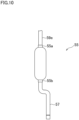
- a muffler 55 (the first component in the present embodiment) is made of stainless steel.
- the muffler 55 includes one first connecting part 55a at the upper end and one second connecting part 55b at the lower end.
- the first connecting part 55a is joined with a refrigerant pipe 59e (the first metal pipe of the present embodiment) by brazing.
- the second connecting part 55b is joined with a refrigerant pipe 57 (the second metal pipe of the present embodiment) by brazing.
- the refrigerant pipe 59e is made of aluminum and is connected to an outdoor heat exchanger 8 through a four-pass switching valve 16.
- the four-pass switching valve 16 is made of stainless steel.
- the refrigerant pipe 57 is made of copper and is connected to a compressor 5. With this arrangement, a refrigerant passage is formed from the refrigerant pipe 59e to the refrigerant pipe 57 through the muffler 55.
- the muffler 55 as a functional component is made of stainless steel, and the refrigerant pipe 59e made of aluminum and the refrigerant pipe 57 made of copper are joined with the muffler 55.
- the refrigerant pipe 59e made of aluminum is not directly joined with the refrigerant pipe 57 made of copper, and hence the galvanic corrosion of the refrigerant pipe 59e is suppressed.
- the muffler 55 that is a known functional component is made of stainless steel and interposed between the refrigerant pipe 59e and the refrigerant pipe 57, it is unnecessary to add another component to suppress the galvanic corrosion of the refrigerant pipe 59e, so as to suppress the manufacturing cost. Furthermore, the present embodiment is able to achieve at least part of the effect of First Embodiment to Fifth Embodiment described above.
- An air conditioner according to the present embodiment is identical with that of First Embodiment, except for the configuration from the outdoor heat exchanger 8 to an accumulator (equivalent to the accumulator 11 shown in FIG. 1 ). Therefore, the following will mainly explain the differences from First Embodiment.
- an accumulator 61 (the first component in the present embodiment) is made of stainless steel.
- the accumulator 61 includes one first connecting part 61a at the upper end and one second connecting part 61b at the upper end.
- the first connecting part 61a is joined with a refrigerant pipe 69d (the first metal pipe of the present embodiment) by brazing.
- the second connecting part 61b is joined with a refrigerant pipe 67 (the second metal pipe of the present embodiment) by brazing.
- the refrigerant pipe 69d is made of aluminum and is connected to an outdoor heat exchanger 8 through a compressor 5, a muffler 15, and a four-pass switching valve 16.
- the compressor 5 and the muffler 15 may be made of aluminum or stainless steel.
- the four-pass switching valve 16 is made of stainless steel.
- the refrigerant pipe 67 is made of copper and is connected to the four-pass switching valve 16. With this arrangement, a refrigerant passage is formed from the refrigerant pipe 69d to the refrigerant pipe 67 through the accumulator 61.
- the accumulator 61 as a functional component is made of stainless steel, and the refrigerant pipe 69d made of aluminum and the refrigerant pipe 67 made of copper are joined with the accumulator 61.
- the refrigerant pipe 69d made of aluminum is not directly joined with the refrigerant pipe 67 made of copper, and hence the galvanic corrosion of the refrigerant pipe 69d is suppressed.
- the accumulator 61 that is a known functional component is made of stainless steel and interposed between the refrigerant pipe 69d and the refrigerant pipe 67, it is unnecessary to add another component to suppress the galvanic corrosion of the refrigerant pipe 69d, so as to suppress the manufacturing cost. Furthermore, the present embodiment is able to achieve at least part of the effect of First Embodiment to Sixth Embodiment described above.
- the liquid receiver 13 may be made of stainless steel
- the refrigerant pipe between the liquid receiver 13 and the outdoor heat exchanger 8 may be made of aluminum
- the refrigerant pipe between the liquid receiver 13 and the liquid stop valve 18 may be made of copper
- the filter 20 may be made of stainless steel
- the refrigerant pipe between the filter 20 and the outdoor heat exchanger 8 may be made of aluminum
- the refrigerant pipe between the filter 20 and the liquid stop valve 18 may be made of copper.
- the first metal pipe is made of aluminum and the second metal pipe is made of copper
- the first metal pipe may be made of a metal different from aluminum and the second metal pipe may be made of a metal different from copper, as long as the electric potential of the material of the second metal pipe is higher than the electric potential of the material of the first metal pipe.
- a heat transfer pipe of a front heat exchanger and a refrigerant pipe connected thereto may be made of aluminum
- a heat transfer pipe of a rear heat exchanger and a refrigerant pipe connected thereto may be made of copper
- a stainless reheat dehumidification valve (decompression valve) may be connected between the heat transfer pipes.
- At least one of the components between the outdoor heat exchanger 8 and the liquid stop valve 18 may be omitted, except the electric expansion valve 7.
- a muffler may be provided between the outdoor heat exchanger 8 and the liquid stop valve 18, and a filter may be provided between the outdoor heat exchanger 8 and the gas stop valve 17.
- the joints formed by brazing in the embodiments described above may be formed by a method other than brazing, such as welding.
- the first component may be entirely made of stainless steel, or may be only partially made of stainless steel.
- the first connecting part may be made of the same metal as the first metal pipe
- the second connecting part may be made of the same metal as the second metal pipe
- a part connecting the first connecting part with the second connecting part may be made of stainless steel.
Landscapes
- Engineering & Computer Science (AREA)
- Mechanical Engineering (AREA)
- General Engineering & Computer Science (AREA)
- Physics & Mathematics (AREA)
- Thermal Sciences (AREA)
- Chemical & Material Sciences (AREA)
- Combustion & Propulsion (AREA)
- Other Air-Conditioning Systems (AREA)
- Compressor (AREA)
- Exhaust Silencers (AREA)
- Pipe Accessories (AREA)
Abstract
Description
- The present disclosure relates to an air conditioner.
- Refrigerant pipes of an air conditioner are typically made of copper or copper alloy. In this regard, in recent years, in order to achieve weight reduction and cost reduction, some of the refrigerant pipes are made of aluminum or aluminum alloy. However, aluminum has a greater tendency to ionize than copper, and when the two come into contact, corrosion (galvanic corrosion) may occur on the aluminum. In Patent Literature 1, in order to prevent corrosion of aluminum caused by condensation water adhering to a refrigerant pipe, a stainless steel joint refrigerant pipe is provided at the joint between an aluminum refrigerant pipe and a copper refrigerant pipe. The stainless steel joint refrigerant pipe is provided between an air blower and a connection pipe that is closest to the air blower among connection pipes connecting heat transfer pipes. This arrangement makes it possible to suppress water droplets that condense on other connection pipes from dropping onto the joint refrigerant pipe.
- [Patent Literature 1] International Publication No.
2016/038865 - According to the technology of Patent Literature 1, it is necessary to add a stainless steel joint refrigerant pipe as a new component, with the result that the number of components increases.
- An object of the present disclosure is to provide an air conditioner with fewer components.
- An air conditioner of the present disclosure includes a first metal pipe, a second metal pipe with a higher electric potential than the first metal pipe, and a first component made of stainless steel and including a first connecting part and a second connecting part. The first metal pipe is connected to the first connecting part of the first component and the second metal pipe is being connected to the second connecting part of the first component, so that a refrigerant passage is formed from the first metal pipe to the second metal pipe through the first component, and the first component is one of a filter, a muffler, a decompression device, a refrigerant storage, and a diverter.
- According to the present disclosure, by connecting functional component made of stainless steel such as a filter between the first metal and the second metal, it is no longer necessary to increase the number of components to suppress the galvanic corrosion, and manufacturing costs can be reduced.
- Preferably, the first connecting part is located above the second connecting part. This makes it possible to suppress the corrosion of the second metal pipe due to condensation water including copper ions and dropping from the first metal pipe.
- Preferably, an end portion of the first connecting part is inserted into the first metal pipe. With this arrangement, detachment due to cooling after the brazing is less likely to occur.
- Preferably, the air conditioner further comprises: a second component connected to the opposite side of the first component of the first metal pipe; and a third component connected to the opposite side of the first component of the second metal pipe, each of the second component and the third component being one of a heat exchanger, a filter, a muffler, a decompression device, a refrigerant storage, a stop valve, and a diverter, the first metal pipe is a refrigerant pipe made of aluminum and the second metal pipe is a refrigerant pipe made of copper, and between the second component and the third component, the number of bended parts of the first metal pipe is smaller than the number of bended parts of the second metal pipe. The number of bended parts of aluminum that is inferior in processability is therefore small, which is advantageous in terms of manufacturing.
- Preferably, the first component is a filter, the first metal pipe is a refrigerant pipe connected to a connection part of the filter on the heat exchanger side, and the first metal pipe includes: a first section connected to the first connecting part of the filter and extending upward from the first connecting part; a second section connected to an upper end portion of the first section, extending upward from the upper end portion, being bended, and extending downward; and a third section connected to a lower end portion of the second section and extending downward. This makes it possible to suppress the corrosion of the second metal pipe due to condensation water including copper ions and dropping from the first metal pipe.
- The first component may be a decompression device, the first metal pipe may be made of aluminum, and the second metal pipe may be made of copper. This arrangement is cost-effective because the aluminum pipe is long, in a case in which the decompression device is preferably positioned as high as possible in order to shorten an electric wire of the air conditioner.
- Preferably, the first component is a diverter, the first metal pipe is a refrigerant pipe connected to an outdoor heat exchanger and made of aluminum, and a decompression device and a stop valve are provided on the opposite side of the outdoor heat exchanger over the diverter, and a pipe between the diverter and the decompression device and a pipe between the decompression device and the stop valve are made of copper. This arrangement is cost-effective as a long refrigerant passage from the diverter to the stop valve through the decompression device is made of copper that excels in processability.
-
-
FIG. 1 is a schematic configuration diagram of an air conditioner related to First Embodiment of the present disclosure. -
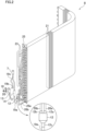
FIG. 2 is a perspective view of an outdoor heat exchanger and some refrigerant pipes included in the air conditioner shown inFIG. 1 and an enlarged view of a filter and its surroundings. -
FIG. 3 is a front view of the outdoor heat exchanger and some of the refrigerant pipes shown inFIG. 2 . -
FIG. 4 is a partial side view of the outdoor heat exchanger and some of the refrigerant pipes shown inFIG. 2 . -
FIG. 5 is an enlarged cross section of a joint between a stainless steel filter and an aluminum refrigerant pipe. -
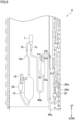
FIG. 6 is a partial side view of an outdoor heat exchanger and some of refrigerant pipes included in an air conditioner of Second Embodiment of the present disclosure. -
FIG. 7 is a partial side view of an outdoor heat exchanger and some of refrigerant pipes included in an air conditioner of Third Embodiment of the present disclosure. -
FIG. 8 is a partial side view of an outdoor heat exchanger and some of refrigerant pipes included in an air conditioner of Fourth Embodiment of the present disclosure. -
FIG. 9 is a partial side view of an outdoor heat exchanger and some of refrigerant pipes included in an air conditioner of Fifth Embodiment of the present disclosure. -
FIG. 10 is a side view of the vicinity of a muffler included in an air conditioner of Sixth Embodiment of the present disclosure. -
FIG. 11 is a side view of the vicinity of an accumulator included in an air conditioner of Seventh Embodiment of the present disclosure. - The following will describe an air conditioner 1 of First Embodiment of the present disclosure. The air conditioner 1 shown in
FIG. 1 includes an indoor unit 2 provided indoors and anoutdoor unit 3 provided outdoors. The indoor unit 2 and theoutdoor unit 3 are connected to each other through arefrigerant pipe 19. - Inside the
outdoor unit 3, there are acompressor 5 configured to compress refrigerant to generate high-temperature and high-pressure gas refrigerant,filters electric expansion valve 7 configured to reduce the pressure of the refrigerant, anoutdoor heat exchanger 8, an accumulator (a type of the refrigerant storage in the present disclosure) 11, amuffler 15, a four-pass switching valve 16, agas stop valve 17, and aliquid stop valve 18. Inside the indoor unit 2, an indoor heat exchanger 6 is provided. These components are connected by therefrigerant pipe 19 to form arefrigerant circuit 4. Theelectric expansion valve 7 is provided with afirst connection pipe 7a and asecond connection pipe 7b. Thefirst connection pipe 7a and thesecond connection pipe 7b are attached to a main body portion of the electric expansion valve 7 (i.e., a portion excluding thefirst connection pipe 7a and thesecond connection pipe 7b) by brazing. - The indoor heat exchanger 6 performs heat exchange between the refrigerant and the room air. In the vicinity of the indoor heat exchanger 6, there is an
indoor fan 9 that is configured to blow the room air to the indoor heat exchanger 6 and to send conditioned air into the room. Thecompressor 5 is configured to compress low-pressure gas refrigerant and to discharge high-pressure gas refrigerant. Thecompressor 5 includes anintake section 5a and adischarge section 5b. Low-pressure gas refrigerant is sucked in from theintake section 5a, and high-pressure gas refrigerant is discharged in a direction indicated by an arrow D from thedischarge section 5b. Theelectric expansion valve 7 is placed between theoutdoor heat exchanger 8 and the indoor heat exchanger 6 in therefrigerant pipe 19 of therefrigerant circuit 4, and is configured to expand and decompress the incoming refrigerant. Thefilters electric expansion valve 7. Theliquid receiver 13 stores refrigerant that has become surplus due to a change in heat load. Theoutdoor heat exchanger 8 performs heat exchange between the refrigerant and the outdoor air. Anoutdoor fan 10 is provided in the vicinity of theoutdoor heat exchanger 8 to blow the outdoor air to theoutdoor heat exchanger 8. - A diverter 12 (a first component in the present embodiment) is placed at an end portion of the
outdoor heat exchanger 8 on theelectric expansion valve 7 side. Thediverter 12 is a functional component in which branched passages are formed. Thediverter 12 is connected to tworefrigerant pipes FIGs. 2 and4 ), and onerefrigerant pipe 19a (second metal pipe of the present embodiment) connected to thefilter 14. Thefilter 14 is connected to thefirst connection pipe 7a of theelectric expansion valve 7 by arefrigerant pipe 19b. Thesecond connection pipe 7b of theelectric expansion valve 7 and theliquid receiver 13 are connected by arefrigerant pipe 19c. Furthermore, theliquid receiver 13, thefilter 20, and theliquid stop valve 18 are also connected by therefrigerant pipe 19c. Furthermore, anaccumulator 11 is connected to therefrigerant pipe 19d on the sucking side of thecompressor 5 to prioritize sending of gas to thecompressor 5 over sending of liquid. Amuffler 15 is connected to therefrigerant pipe 19e on the discharging side of thecompressor 5 to reduce pressure pulsation of the refrigerant discharged from thecompressor 5. - The
refrigerant pipe 19 is connected to the four-pass switching valve 16 for switching the refrigerant passage, thegas stop valve 17, and theliquid stop valve 18. By switching the four-pass switching valve 16, the flow of refrigerant is reversed, and the refrigerant discharged from thecompressor 5 is supplied to either theoutdoor heat exchanger 8 or the indoor heat exchanger 6 so as to switch between a cooling operation and a warming operation. Thegas stop valve 17 and theliquid stop valve 18 are made of brass and are used to open or close the refrigerant passage. - During the warming operation of the air conditioner 1, the four-
pass switching valve 16 is switched as indicated by solid lines inFIG. 1 to flow the refrigerant in directions indicated by solid arrows. As a result, the high-pressure gas refrigerant discharged from thecompressor 5 in the direction indicated by the arrow D passes through themuffler 15 and the four-pass switching valve 16, then passes through thegas stop valve 17 and enters the indoor heat exchanger 6. The high-pressure gas refrigerant releases heat during the process of becoming high-pressure liquid refrigerant in the indoor heat exchanger 6. The high-pressure liquid refrigerant reaches theelectric expansion valve 7 through theliquid stop valve 18 having been opened, and is decompressed by theelectric expansion valve 7. The decompressed refrigerant reaches theoutdoor heat exchanger 8, absorbs heat at theoutdoor heat exchanger 8, and becomes low-pressure gas refrigerant. The low-pressure gas refrigerant is sucked into thecompressor 5 through the four-pass switching valve 16 and theaccumulator 11. During the warming operation, the indoor heat exchanger 6 functions as a heat radiator, and theoutdoor heat exchanger 8 functions as a heat absorber. - On the other hand, during the cooling operation, the four-
pass switching valve 16 is switched as indicated by dotted lines inFIG. 1 to reverse the flow of the refrigerant, with the result that the refrigerant flows in directions indicated by dotted arrows. Consequently, the high-pressure gas refrigerant discharged from thecompressor 5 in the direction indicated by the arrow D passes through themuffler 15 and the four-pass switching valve 16, and then enters theoutdoor heat exchanger 8. The high-pressure gas refrigerant releases heat during the process of becoming high-pressure liquid refrigerant in theoutdoor heat exchanger 8. The high-pressure liquid refrigerant reaches theelectric expansion valve 7 and is decompressed by theelectric expansion valve 7. The decompressed refrigerant reaches the indoor heat exchanger 6 through theliquid stop valve 18 having been opened, absorbs heat at the indoor heat exchanger 6, and becomes low-pressure gas refrigerant. The low-pressure gas refrigerant is sucked into thecompressor 5 through thegas stop valve 17, the four-pass switching valve 16, and theaccumulator 11. During the cooling operation, the indoor heat exchanger 6 functions as a heat absorber, and theoutdoor heat exchanger 8 functions as a heat radiator. - As shown in
FIGs. 2 and3 , theoutdoor heat exchanger 8 includes a plurality offlat fins 21 stacked at predetermined intervals and a plurality ofheat transfer pipes 22 inserted into multiple through holes provided in each fin 21 (only one of them is indicated by dotted lines inFIG. 3 . Eachheat transfer pipe 22 is bent to be L-shaped, and theoutdoor heat exchanger 8 is substantially L-shaped when viewed from above. Except end portions functioning as (two) entrances and (two) exits of refrigerant to and from theoutdoor heat exchanger 8, each end portion where an opening of theheat transfer pipe 22 is provided is connected by a U-bend 23 with an end portion where an opening of anotherheat transfer pipe 22 is provided. In this way, two passages through which the refrigerant passes are formed in theoutdoor heat exchanger 8 of the present embodiment. Thefins 21, theheat transfer pipes 22, and the U-bend 23 are made of aluminum or aluminum alloy (hereinafter, this will be simply referred to as "made of aluminum" in the present disclosure). The heat transfer pipes may be hairpin tubes. - There is an
end plate 25 constituted by a steel plate or the like on the outer side of theoutermost fin 21. Theheat transfer pipes 22 penetrate theend plate 25 and are connected to the U-bends 23 on the outer side of theend plate 25. An end portion of eachheat transfer pipe 22, which is not connected to the U-bend 23, is connected to a refrigerant pipe connected to the above-described two passages formed in theoutdoor heat exchanger 8.FIG. 2 andFIG. 4 show tworefrigerant pipes diverter 12, among the refrigerant pipes. In the following explanation, the up-down relationship will be described with reference toFIG. 4 . - In the present embodiment, the
refrigerant pipes diverter 12 is made of stainless steel. Therefrigerant pipes diverter 12 are made of copper or copper alloy having a higher electric potential than aluminum (they will be simply referred to as "made of copper" in the present disclosure). Thefilter 14, theliquid receiver 13, and thefilter 20 are also made of copper, theelectric expansion valve 7 has a main body portion made of stainless steel, and thefirst connection pipe 7a and thesecond connection pipe 7b are made of copper. With reference toFIG. 2 , thediverter 12 includes two first connectingparts part 12c. The first connectingparts refrigerant pipes unit 12c is joined with therefrigerant pipe 19a by brazing. With this arrangement, a refrigerant passage is formed from therefrigerant pipes refrigerant pipe 19a through thediverter 12. In thediverter 12, a branching passage is formed to connect the first connectingparts part 12c. In the present embodiment, the first connectingparts part 12c. - As such, in the air conditioner 1 according to the present embodiment, the
diverter 12 as a functional component is made of stainless steel, and therefrigerant pipes refrigerant pipe 19a made of copper are joined with thediverter 12. With this arrangement, therefrigerant pipes refrigerant pipe 19a made of copper, and hence the galvanic corrosion of therefrigerant pipes diverter 12 that is a known functional component is made of stainless steel and interposed between therefrigerant pipes refrigerant pipe 19a, it is unnecessary to add another component to suppress the galvanic corrosion of therefrigerant pipes parts part 12c, even if condensation water containing copper ions adheres to the surface of thecopper refrigerant pipe 19a and falls due to condensation, the condensation water will not adhere to thealuminum refrigerant pipes refrigerant pipes - In the air conditioner 1 according to the present embodiment, the
refrigerant pipes diverter 12 and theoutdoor heat exchanger 8 are made of aluminum, whereas thelong refrigerant pipes diverter 12 through theelectric expansion valve 7 to theliquid stop valve 18 are made of copper. As such, in the present embodiment, most of the refrigerant pipes from theoutdoor heat exchanger 8 to theliquid stop valve 18 are made of copper having excellent processability, which is advantageous in terms of manufacturing. - The details of the joining of the
diverter 12 with the refrigerant pipes will be explained with reference toFIG. 5 . While the following explanation deals with the joining of the first connectingpart 12a with therefrigerant pipe 26a as an example, the same applies to the joining of the first connectingpart 12b with therefrigerant pipe 26b. As shown inFIG. 5 , a lower end portion (right end portion inFIG. 5 ) of therefrigerant pipe 26a and its surroundings are expanded in diameter. The inner diameter of the expanded part is slightly larger than the outer diameter of the first connectingpart 12a. The outer diameter and the inner diameter of the first connectingpart 12a are identical with those of a non-expanded part of therefrigerant pipe 26a. An upper end portion (left end portion inFigure 5 ) of the first connectingpart 12a and its surroundings are inserted into the expanded lower end portion and its surroundings of therefrigerant pipe 26a. The upper end portion of the first connectingpart 12a and its surroundings and the expanded lower end portion of therefrigerant pipe 26a and its surroundings are joined together by brazing as described above, and abrazing material 28 is interposed between them. - Aluminum has a higher linear expansion coefficient than stainless steel. The solidification temperature of the
brazing material 28 in the brazing process is a high temperature of about 580 degrees centigrade. The amount of contraction of therefrigerant pipe 26a inward is greater than the amount of contraction of the first connectingpart 12a inward, during a process of cooling of thealuminum refrigerant pipe 26a and the stainless steel first connectingpart 12a from the solidification temperature to a room temperature. In the present embodiment, because the upper end portion of the first connectingpart 12a and its surroundings are inserted into the lower end portion of therefrigerant pipe 26a and its surroundings, thebrazing material 28 sandwiched between (i) the upper end portion of the first connectingpart 12a and its surroundings, which significantly contract inward, and (ii) the lower end portion of therefrigerant pipe 26a and its surroundings, which contract inward less than the upper end portion and its surroundings, receives a stress causing thebrazing material 28 to contract in the radial direction, in the cooling process after the brazing process. Therefore, as compared to a case where the lower end portion of therefrigerant pipe 26a and its surroundings are inserted into the upper end portion of the first connectingpart 12a and its surroundings, it is possible to reduce the occurrence of detachment at the brazing point and improve the reliability of the joining. - Copper has a higher linear expansion coefficient than many types of stainless steel materials, but has a lower linear expansion coefficient than some types of stainless steel materials. Therefore, when the linear expansion coefficient of the stainless steel material of the
diverter 12 is higher than the linear expansion coefficient of the copper material of therefrigerant pipe 19a, it is preferable that therefrigerant pipe 26a is inserted into the first connectingpart 12a. Conversely, when the opposite is true, it is preferable that the first connectingpart 12a is inserted into therefrigerant pipe 26a. In the embodiments described below, a brazed joint between a stainless steel functional component and an aluminum refrigerant pipe and a brazed joint between a stainless steel functional component and a copper refrigerant pipe have the same structures as in the present embodiment. - The following will describe an air conditioner of Second Embodiment of the present disclosure. The air conditioner according to the present embodiment is identical with that of First Embodiment, except for the configuration related to the diverter and the adjacent filter. Therefore, the following will mainly explain the differences from First Embodiment.
- In
FIG. 6 , a diverter 32 (the second component in the present embodiment) is made of aluminum, and a filter 34 (the first component in the present embodiment) is made of stainless steel. Arefrigerant pipe 39a (the first metal pipe in the present embodiment) between thediverter 32 and thefilter 34 is made of aluminum. Arefrigerant pipe 19b (the second metal pipe in the present embodiment) between thefilter 34 and an electric expansion valve 7 (the third component in the present embodiment) is made of copper in the same manner as in First Embodiment. Thefilter 34 includes one first connectingpart 34a at the lower end and one second connectingpart 34b at the upper end. The first connectingpart 34a is joined with therefrigerant pipe 39a by brazing. The second connectingunit 34b is joined with therefrigerant pipe 19b by brazing. With this arrangement, a refrigerant passage is formed from therefrigerant pipe 39a to therefrigerant pipe 19b through thefilter 34. In thefilter 34, a mesh member with numerous fine holes is provided. - As such, in the air conditioner according to the present embodiment, the
filter 34 as a functional component is made of stainless steel, and therefrigerant pipe 39a made of aluminum and therefrigerant pipe 19b made of copper are joined with thefilter 34. With this arrangement, therefrigerant pipe 39a made of aluminum is not directly joined with therefrigerant pipe 19b made of copper, and hence the galvanic corrosion of therefrigerant pipe 39a is suppressed. Furthermore, because thefilter 34 that is a known functional component is made of stainless steel and interposed between therefrigerant pipe 39a and therefrigerant pipe 19b, it is unnecessary to add another component to suppress the galvanic corrosion of therefrigerant pipe 39a, so as to suppress the manufacturing cost. - In the air conditioner according to the present embodiment, the
aluminum refrigerant pipe 39a between thediverter 32 and thefilter 34 is substantially U-shaped, with only one bended part. In contrast, as shown inFIG. 6 , therefrigerant pipe 19b between thefilter 34 and theelectric expansion valve 7 is shaped to have a vertical section directly above thefilter 34, an oblique section, and a vertical section directly below theelectric expansion valve 7 which are connected with one another. As such, there are two bended parts. In this way, in the present embodiment, between thediverter 32 and theelectric expansion valve 7, there are fewer processed parts in thealuminum refrigerant pipe 39a that is made of aluminum and is poor in processability. On this account, the manufacturing can be easily done. Furthermore, between theoutdoor heat exchanger 8 and theliquid stop valve 18, the number of bended parts of thealuminum refrigerant pipes filter 34 and theoutdoor heat exchanger 8 is smaller than the number of bended parts of thecopper refrigerant pipes filter 34 and theliquid stop valve 18. On this account, the manufacturing can be easily done. Furthermore, the present embodiment is able to achieve at least part of the effect of First Embodiment described above. - The following will describe an air conditioner of Third Embodiment of the present disclosure. The air conditioner according to the present embodiment is identical with that of Second Embodiment, except for the configuration from the filter to the electric expansion valve. Therefore, the following will mainly explain the differences from Second Embodiment.
- In
FIG. 7 , a filter 35 (the second component in the present embodiment) is made of aluminum, and an electric expansion valve 37 (the first component in the present embodiment) is arranged such that a main body portion is made of stainless steel, afirst connection pipe 37a is made of aluminum, and asecond connection pipe 37b is made of copper. Arefrigerant pipe 39b (the first metal pipe in the present embodiment) between thefilter 35 and theelectric expansion valve 37 is made of aluminum. Arefrigerant pipe 19c (the second metal pipe in the present embodiment) between theelectric expansion valve 37 and a liquid receiver 13 (the third component in the present embodiment) is made of copper in the same manner as in First Embodiment. A first connectingpart 37a of theelectric expansion valve 37 is joined with therefrigerant pipe 39b by brazing. The second connectingunit 37b is joined with therefrigerant pipe 19c by brazing. With this arrangement, a refrigerant passage is formed from therefrigerant pipe 39b to therefrigerant pipe 19c through theelectric expansion valve 37. In theelectric expansion valve 37, a stepping motor that allows for almost stepless adjustment of the opening degree is provided. - As such, in the air conditioner according to the present embodiment, a main body portion of the
electric expansion valve 37 as a functional component is made of stainless steel, and therefrigerant pipe 39b made of aluminum and therefrigerant pipe 19c made of copper are joined with thefirst connection pipe 37a made of aluminum and thesecond connection pipe 37b made of copper of theelectric expansion valve 37, respectively. With this arrangement, therefrigerant pipe 39b made of aluminum is not directly joined with therefrigerant pipe 19c made of copper, and hence the galvanic corrosion of therefrigerant pipe 39b is suppressed. Furthermore, because the main body portion of theelectric expansion valve 37 that is a known functional component is made of stainless steel and interposed between therefrigerant pipe 39b and therefrigerant pipe 19c, it is unnecessary to add another component to suppress the galvanic corrosion of therefrigerant pipe 39a, so as to suppress the manufacturing cost. - In the air conditioner according to the present embodiment, the
electric expansion valve 37, which is a decompression device, is positioned to be higher than the functional components (adiverter 32, afilter 35, aliquid receiver 13, and a filter 20) located between anoutdoor heat exchanger 8 and aliquid stop valve 18 shown inFIG. 7 . An electronic board (not illustrated) connected to theelectric expansion valve 37 by an electric wire tends to be placed at a relatively high position inside theoutdoor unit 3. Therefore, when theelectric expansion valve 37 is made of stainless steel and therefrigerant pipes outdoor heat exchanger 8 and thefirst connection pipe 37a are made of aluminum, the electric wire between the electronic board and theelectric expansion valve 37 is short, and this is advantageous in cost. - In the air conditioner of the present embodiment, furthermore, the
refrigerant pipe 39b made of aluminum and provided between thefilter 35 and theelectric expansion valve 37 is shaped to have a vertical section directly above thefilter 35, an oblique section, and a vertical section directly below theelectric expansion valve 37 which are connected with one another, as shown inFIG. 7 . As such, there are two bended parts. In contrast, therefrigerant pipe 19c which is made of copper and provided between theelectric expansion valve 37 and theliquid receiver 13 is shaped to have a vertical section directly below thesecond connection pipe 37b, a section extending obliquely forward and downward, a section extending obliquely rearward and downward, and a vertical section directly above the liquid receiver 13 (seeFIG. 3 ) which are connected with one another. As such, there are three bended parts. In this way, in the present embodiment, between thefilter 35 and theliquid receiver 13, there are fewer processed parts in thealuminum refrigerant pipe 39b that is made of aluminum and is poor in processability. On this account, the manufacturing can be easily done. Furthermore, between theoutdoor heat exchanger 8 and theliquid stop valve 18, the number of bended parts of thealuminum refrigerant pipes electric expansion valve 37 and theoutdoor heat exchanger 8 is smaller than the number of bended parts of thecopper refrigerant pipe 19c between theelectric expansion valve 37 and theliquid stop valve 18. On this account, the manufacturing can be easily done. Furthermore, the present embodiment is able to achieve at least part of the effect of First Embodiment and Second Embodiment described above. - The following will describe an air conditioner of Fourth Embodiment of the present disclosure. The air conditioner according to the present embodiment is identical with that of Third Embodiment, except for the configuration related to the electric expansion valve. Therefore, the following will mainly explain the differences from Third Embodiment.
- In
FIG. 8 , a filter 35 (the second component in the present embodiment) is made of aluminum, and an electric expansion valve 38 (the first component in the present embodiment) is arranged such that a main body portion, afirst connection pipe 38a, and asecond connection pipe 38b are made of stainless steel. Arefrigerant pipe 39b (the first metal pipe in the present embodiment) between thefilter 35 and theelectric expansion valve 38 is made of aluminum. Arefrigerant pipe 19c (the second metal pipe in the present embodiment) between theelectric expansion valve 38 and a liquid receiver 13 (the third component in the present embodiment) is made of copper in the same manner as in First Embodiment. A first connectingpart 38a of theelectric expansion valve 38 is joined with therefrigerant pipe 39b by brazing. The second connectingunit 38b is joined with therefrigerant pipe 19c by brazing. With this arrangement, a refrigerant passage is formed from therefrigerant pipe 39b to therefrigerant pipe 19c through theelectric expansion valve 38. - Also in the present embodiment, a main body portion of the
electric expansion valve 38 as a functional component is made of stainless steel, and therefrigerant pipe 39b made of aluminum and therefrigerant pipe 19c made of copper are joined with thefirst connection pipe 38a made of aluminum and thesecond connection pipe 38b made of stainless steel of theelectric expansion valve 37, respectively. With this arrangement, the galvanic corrosion of therefrigerant pipe 39b is suppressed. Furthermore, it is unnecessary to add another component to suppress the galvanic corrosion of therefrigerant pipe 39a, so as to suppress the manufacturing cost. - In the present embodiment, the main body portion of the
electric expansion valve 38 is made of stainless steel, and the main body portion is joined with thefirst connection pipe 38a and thesecond connection pipe 38b, which are also made of stainless steel, by brazing. Therefore, brazing of both of the pipes can be performed at the same time, with the result that the manufacturing process of theelectric expansion valve 38 is simplified. Furthermore, because thesecond connection pipe 38b is made of not copper but stainless steel, even if condensation water adhering to the surface of thesecond connection pipe 38b adheres to members such as thealuminum refrigerant pipe 39b, the galvanic corrosion is less likely to occur in the members such as therefrigerant pipe 39b, because this condensation water does not include copper ions. Furthermore, the present embodiment is able to achieve at least part of the effect of First Embodiment to Third Embodiment described above. - The following will describe an air conditioner of Fifth Embodiment of the present disclosure. The air conditioner according to the present embodiment is identical with that of Second Embodiment, except for the configuration from the diverter to the electric expansion valve. Therefore, the following will mainly explain the differences from Second Embodiment.
- In
FIG. 9 , a filter 45 (the first component in the present embodiment) is made of stainless steel. Arefrigerant pipe 49a (the first metal pipe in the present embodiment) between thefilter 45 and a diverter 32 (the second component of the present embodiment) is made of aluminum. Arefrigerant pipe 49b (the second metal pipe in the present embodiment) between thefilter 45 and an electric expansion valve 7 (the third component in the present embodiment) is made of copper in the same manner as in First Embodiment. Thefilter 45 includes one first connectingpart 45a at the upper end and one second connectingpart 45b at the lower end. The first connectingpart 45a is joined with therefrigerant pipe 49a by brazing. The second connectingunit 45b is joined with the refrigerant pipe 49c by brazing. With this arrangement, a refrigerant passage is formed from therefrigerant pipe 49a to therefrigerant pipe 49b through thefilter 45. - As such, in the air conditioner according to the present embodiment, the
filter 45 as a functional component is made of stainless steel, and therefrigerant pipe 49a made of aluminum and therefrigerant pipe 49b made of copper are joined with thefilter 45. With this arrangement, therefrigerant pipe 49b made of aluminum is not directly joined with the refrigerant pipe 49c made of copper, and hence the galvanic corrosion of therefrigerant pipe 49a is suppressed. Furthermore, because thefilter 45 that is a known functional component is made of stainless steel and interposed between therefrigerant pipe 49a and therefrigerant pipe 49b, it is unnecessary to add another component to suppress the galvanic corrosion of therefrigerant pipe 49a, so as to suppress the manufacturing cost. - Furthermore, in the present embodiment, the
refrigerant pipe 49a which is on theoutdoor heat exchanger 8 side of thefilter 45 and connected to thefirst connection pipe 45a includes three sections that will be described below. A first section PA is connected to the first connectingpart 45a of thefilter 45 and extends upward from the first connectingpart 45a. A second section PB is connected to an upper end portion of the first section PA, extends upward from the upper end portion, and is bended and extends downward. In other words, the second section PB is U-shaped. A third section PC is connected to a lower end portion of the second section PB and extends downward. By arranging therefrigerant pipe 49a to have the three sections PA, PB, and PC described above, even when therefrigerant pipes diverter 32 are provided in the vicinity of the lower end of theoutdoor heat exchanger 8, the junction with thealuminum refrigerant pipe 49a is the upper end of thefilter 45 and the junction with thecopper refrigerant pipe 49b is the lower end of thefilter 45. This makes it possible to suppress the corrosion of therefrigerant pipe 49a due to condensation water including copper ions and dropping from therefrigerant pipe 49b. In the example shown inFIG. 9 , the first section PA and the third section PC extend in the vertical direction. However, the first section PA and the third section PC may not extend in the vertical direction, and may be inclined with respect to the vertical direction. Furthermore, the present embodiment is able to achieve at least part of the effect of First Embodiment to Fourth Embodiment described above. - The following will describe an air conditioner of Sixth Embodiment of the present disclosure. An air conditioner according to the present embodiment is identical with that of First Embodiment, except for the configuration from the
outdoor heat exchanger 8 to a muffler (equivalent to themuffler 15 shown inFIG. 1 ). Therefore, the following will mainly explain the differences from First Embodiment. - In
FIG. 10 , a muffler 55 (the first component in the present embodiment) is made of stainless steel. Themuffler 55 includes one first connectingpart 55a at the upper end and one second connectingpart 55b at the lower end. The first connectingpart 55a is joined with arefrigerant pipe 59e (the first metal pipe of the present embodiment) by brazing. The second connectingpart 55b is joined with a refrigerant pipe 57 (the second metal pipe of the present embodiment) by brazing. Therefrigerant pipe 59e is made of aluminum and is connected to anoutdoor heat exchanger 8 through a four-pass switching valve 16. The four-pass switching valve 16 is made of stainless steel. Therefrigerant pipe 57 is made of copper and is connected to acompressor 5. With this arrangement, a refrigerant passage is formed from therefrigerant pipe 59e to therefrigerant pipe 57 through themuffler 55. - As such, in the air conditioner according to the present embodiment, the
muffler 55 as a functional component is made of stainless steel, and therefrigerant pipe 59e made of aluminum and therefrigerant pipe 57 made of copper are joined with themuffler 55. With this arrangement, therefrigerant pipe 59e made of aluminum is not directly joined with therefrigerant pipe 57 made of copper, and hence the galvanic corrosion of therefrigerant pipe 59e is suppressed. Furthermore, because themuffler 55 that is a known functional component is made of stainless steel and interposed between therefrigerant pipe 59e and therefrigerant pipe 57, it is unnecessary to add another component to suppress the galvanic corrosion of therefrigerant pipe 59e, so as to suppress the manufacturing cost. Furthermore, the present embodiment is able to achieve at least part of the effect of First Embodiment to Fifth Embodiment described above. - The following will describe an air conditioner of Seventh Embodiment of the present disclosure. An air conditioner according to the present embodiment is identical with that of First Embodiment, except for the configuration from the
outdoor heat exchanger 8 to an accumulator (equivalent to theaccumulator 11 shown inFIG. 1 ). Therefore, the following will mainly explain the differences from First Embodiment. - In
FIG. 11 , an accumulator 61 (the first component in the present embodiment) is made of stainless steel. Theaccumulator 61 includes one first connectingpart 61a at the upper end and one second connectingpart 61b at the upper end. The first connectingpart 61a is joined with arefrigerant pipe 69d (the first metal pipe of the present embodiment) by brazing. The second connectingpart 61b is joined with a refrigerant pipe 67 (the second metal pipe of the present embodiment) by brazing. Therefrigerant pipe 69d is made of aluminum and is connected to anoutdoor heat exchanger 8 through acompressor 5, amuffler 15, and a four-pass switching valve 16. Thecompressor 5 and themuffler 15 may be made of aluminum or stainless steel. The four-pass switching valve 16 is made of stainless steel. Therefrigerant pipe 67 is made of copper and is connected to the four-pass switching valve 16. With this arrangement, a refrigerant passage is formed from therefrigerant pipe 69d to therefrigerant pipe 67 through theaccumulator 61. - As such, in the air conditioner according to the present embodiment, the
accumulator 61 as a functional component is made of stainless steel, and therefrigerant pipe 69d made of aluminum and therefrigerant pipe 67 made of copper are joined with theaccumulator 61. With this arrangement, therefrigerant pipe 69d made of aluminum is not directly joined with therefrigerant pipe 67 made of copper, and hence the galvanic corrosion of therefrigerant pipe 69d is suppressed. Furthermore, because theaccumulator 61 that is a known functional component is made of stainless steel and interposed between therefrigerant pipe 69d and therefrigerant pipe 67, it is unnecessary to add another component to suppress the galvanic corrosion of therefrigerant pipe 69d, so as to suppress the manufacturing cost. Furthermore, the present embodiment is able to achieve at least part of the effect of First Embodiment to Sixth Embodiment described above. - In First to Fifth Embodiments, the
liquid receiver 13 may be made of stainless steel, the refrigerant pipe between theliquid receiver 13 and theoutdoor heat exchanger 8 may be made of aluminum, and the refrigerant pipe between theliquid receiver 13 and theliquid stop valve 18 may be made of copper. In First to Fifth Embodiments, thefilter 20 may be made of stainless steel, the refrigerant pipe between thefilter 20 and theoutdoor heat exchanger 8 may be made of aluminum, and the refrigerant pipe between thefilter 20 and theliquid stop valve 18 may be made of copper. While in the embodiments described above the first metal pipe is made of aluminum and the second metal pipe is made of copper, the first metal pipe may be made of a metal different from aluminum and the second metal pipe may be made of a metal different from copper, as long as the electric potential of the material of the second metal pipe is higher than the electric potential of the material of the first metal pipe. - While the embodiments described above relate to the functional components and the refrigerant pipes in the outdoor heat exchanger, the present disclosure may be applicable to functional components and refrigerant pipes in an indoor heat exchanger. For example, in the indoor unit, a heat transfer pipe of a front heat exchanger and a refrigerant pipe connected thereto may be made of aluminum, a heat transfer pipe of a rear heat exchanger and a refrigerant pipe connected thereto may be made of copper, and a stainless reheat dehumidification valve (decompression valve) may be connected between the heat transfer pipes.
- In First to Fifth Embodiments, at least one of the components between the
outdoor heat exchanger 8 and theliquid stop valve 18 may be omitted, except theelectric expansion valve 7. A muffler may be provided between theoutdoor heat exchanger 8 and theliquid stop valve 18, and a filter may be provided between theoutdoor heat exchanger 8 and thegas stop valve 17. The joints formed by brazing in the embodiments described above may be formed by a method other than brazing, such as welding. The first component may be entirely made of stainless steel, or may be only partially made of stainless steel. For example, the first connecting part may be made of the same metal as the first metal pipe, the second connecting part may be made of the same metal as the second metal pipe, and a part connecting the first connecting part with the second connecting part may be made of stainless steel. - Although the embodiments have been described above, it will be understood that various changes in form and details are possible as long as the changes do not depart from the spirit and scope of the claims.
-
- 1 air conditioner
- 2 indoor unit
- 3 outdoor unit
- 6 indoor heat exchanger
- 7 electric expansion valve
- 7a first connection pipe
- 7b Second connection pipe
- 8 outdoor heat exchanger
- 11 accumulator
- 12 diverter
- 12a, 12b first connecting part
- 12c second connecting part
- 13 liquid receiver
- 14, 20 filter
- 15 muffler
- 16 four-pass switching valve
- 17 gas stop valve
- 18 liquid stop valve
- 19 (19a, 19b, 19c) refrigerant pipe
- 26a, 26b refrigerant pipe
Claims (7)
- An air conditioner comprising:a first metal pipe (26a, 26b; 39a; 39b; 39b; 49a; 59e; 69d); a second metal pipe (19a; 19b; 19c; 19c; 49b; 57; 67) with a higher electric potential than the first metal pipe; and a first component (12; 34; 37; 38; 45; 55; 61) made of stainless steel and including a first connecting part (12a, 12b; 34a; 37a; 38a; 45a; 55a; 61a) and a second connecting part (12c; 34b; 37b; 38b; 45b; 55b; 61b),the first metal pipe being connected to the first connecting part of the first component and the second metal pipe being connected to the second connecting part of the first component, so that a refrigerant passage is formed from the first metal pipe to the second metal pipe through the first component, and the first component being one of a filter (34; 45), a muffler (55), a decompression device (37; 38), a refrigerant storage (61), and a diverter (12).
- The air conditioner according to claim 1, wherein, the first connecting part (12a, 12b; 45a; 55a) is located above the second connecting part (12c; 45b; 55b).
- The air conditioner according to claim 1 or 2, wherein an end portion of the first connecting part (12a, 12b; 34a; 37a; 38a; 45a; 55a; 61a) is inserted into the first metal pipe (26a, 26b; 39a; 39b; 39b; 49a; 59e; 69d).
- The air conditioner according to any one of claims 1 to 3, further comprising: a second component (32; 35; 35; 32) connected to the opposite side of the first component of the first metal pipe (39a; 39b; 39b; 49a); and a third component (7; 13; 13; 7) connected to the opposite side of the first component of the second metal pipe (19b; 19c; 19c; 49b),each of the second component and the third component being one of a heat exchanger, a filter, a muffler, a decompression device, a refrigerant storage, a stop valve, and a diverter,the first metal pipe (39a; 39b; 39b; 49a) being a refrigerant pipe made of aluminum and the second metal pipe (19b; 19c; 19c; 49b) being a refrigerant pipe made of copper, andbetween the second component (32; 35; 35; 32) and the third component (7; 13; 13; 7), the number of bended parts of the first metal pipe being smaller than the number of bended parts of the second metal pipe.
- The air conditioner according to any one of claims 1 to 4, wherein,the first component is a filter (45),the first metal pipe (49a) is a refrigerant pipe connected to a connection part of the filter on the heat exchanger side, andthe first metal pipe (49a) includes: a first section (PA) connected to the first connecting part (45a) of the filter and extending upward from the first connecting part; a second section (PB) connected to an upper end portion of the first section, extending upward from the upper end portion, being bended, and extending downward; and a third section (PC) connected to a lower end portion of the second section and extending downward.
- The air conditioner according to any one of claims 1 to 4, wherein, the first component is a decompression device (37; 38), the first metal pipe (39b; 39b) is made of aluminum, and the second metal pipe (19c; 19c) is made of copper.
- The air conditioner according to any one of claims 1 to 4, wherein,the first component is a diverter (12), the first metal pipe is a refrigerant pipe (26a, 26b) connected to an outdoor heat exchanger (8) and made of aluminum, and a decompression device (7) and a stop valve (18) are provided on the opposite side of the outdoor heat exchanger (8) over the diverter, anda pipe (19a, 19b) between the diverter (12) and the decompression device (7) and a pipe (19c) between the decompression device (7) and the stop valve (18) are made of copper.
Applications Claiming Priority (2)
| Application Number | Priority Date | Filing Date | Title |
|---|---|---|---|
| JP2021161635A JP7239857B1 (en) | 2021-09-30 | 2021-09-30 | air conditioner |
| PCT/JP2022/022162 WO2023053577A1 (en) | 2021-09-30 | 2022-05-31 | Air conditioner |
Publications (3)
| Publication Number | Publication Date |
|---|---|
| EP4411288A1 true EP4411288A1 (en) | 2024-08-07 |
| EP4411288A4 EP4411288A4 (en) | 2025-01-15 |
| EP4411288B1 EP4411288B1 (en) | 2025-12-24 |
Family
ID=85569518
Family Applications (1)
| Application Number | Title | Priority Date | Filing Date |
|---|---|---|---|
| EP22875456.0A Active EP4411288B1 (en) | 2021-09-30 | 2022-05-31 | Air conditioner |
Country Status (6)
| Country | Link |
|---|---|
| US (1) | US20240392978A1 (en) |
| EP (1) | EP4411288B1 (en) |
| JP (1) | JP7239857B1 (en) |
| CN (1) | CN117980669B (en) |
| ES (1) | ES3059648T3 (en) |
| WO (1) | WO2023053577A1 (en) |
Families Citing this family (3)
| Publication number | Priority date | Publication date | Assignee | Title |
|---|---|---|---|---|
| JP7239857B1 (en) * | 2021-09-30 | 2023-03-15 | ダイキン工業株式会社 | air conditioner |
| JP7839763B2 (en) * | 2023-04-03 | 2026-04-02 | 株式会社鷺宮製作所 | Valve devices and refrigeration cycle systems |
| WO2026062866A1 (en) * | 2024-09-20 | 2026-03-26 | ボッシュホームコンフォートジャパン株式会社 | Air conditioner |
Family Cites Families (72)
| Publication number | Priority date | Publication date | Assignee | Title |
|---|---|---|---|---|
| US4041726A (en) * | 1976-03-29 | 1977-08-16 | Paul Mueller Company | Hot water system |
| US4305456A (en) * | 1977-08-12 | 1981-12-15 | Paul Mueller Company | Condenser and hot water system |
| JPH0338602Y2 (en) * | 1984-11-22 | 1991-08-14 | ||
| US5220807A (en) * | 1991-08-27 | 1993-06-22 | Davis Energy Group, Inc. | Combined refrigerator water heater |
| US5351502A (en) * | 1991-10-30 | 1994-10-04 | Lennox Industries, Inc. | Combination ancillary heat pump for producing domestic hot h20 with multimodal dehumidification apparatus |
| US5205133A (en) * | 1992-01-16 | 1993-04-27 | R & D Technologies, Inc. | High efficiency pool heating system |
| JP3216960B2 (en) * | 1994-09-19 | 2001-10-09 | 株式会社日立製作所 | Outdoor unit and indoor unit of air conditioner and refrigerant distributor used for them |
| US5901573A (en) * | 1995-11-02 | 1999-05-11 | Calsonic Corporation | Condenser structure with liquid tank |
| US5896921A (en) * | 1997-05-27 | 1999-04-27 | Daewoo Electronics Co., Ltd. | Indoor unit of an air conditioner |
| EP0962725B1 (en) * | 1997-12-16 | 2017-11-08 | Panasonic Corporation | Airconditioner using inflammable refrigerant |
| JPH11237140A (en) * | 1998-02-20 | 1999-08-31 | Hitachi Cable Ltd | Refrigerant refrigerant piping |
| JP3227651B2 (en) * | 1998-11-18 | 2001-11-12 | 株式会社デンソー | Water heater |
| TW200300205A (en) * | 2001-11-13 | 2003-05-16 | Pacific Engineering Corp | Refrigeration Circuit |
| US6793121B2 (en) * | 2002-03-12 | 2004-09-21 | Newfield Technology Corporation | Clasp having a flange to couple a heat exchanger to a device in a cooling system |
| US6606881B1 (en) * | 2002-05-20 | 2003-08-19 | American Standard International Inc. | Absorption solution conditioner |
| JP2005090761A (en) * | 2003-09-12 | 2005-04-07 | Matsushita Electric Ind Co Ltd | Air conditioner |
| JP2005106367A (en) * | 2003-09-30 | 2005-04-21 | Daikin Ind Ltd | Air conditioner outdoor unit, air conditioner, and compressor unit |
| JP2005114283A (en) * | 2003-10-09 | 2005-04-28 | Calsonic Kansei Corp | Vehicular air conditioner |
| US20050086965A1 (en) * | 2003-10-22 | 2005-04-28 | Rejean Lalumiere | Cooling mechanism for refrigeration systems |
| US7024877B2 (en) * | 2003-12-01 | 2006-04-11 | Tecumseh Products Company | Water heating system |
| KR20060025082A (en) * | 2004-09-15 | 2006-03-20 | 삼성전자주식회사 | Evaporator Using Microchannel Tube |
| KR20070004340A (en) * | 2005-07-04 | 2007-01-09 | 삼성전자주식회사 | Piping type filter and air conditioner with same |
| JP4592616B2 (en) * | 2006-02-27 | 2010-12-01 | 三洋電機株式会社 | Refrigeration cycle equipment |
| US7617697B2 (en) * | 2006-05-16 | 2009-11-17 | Mccaughan Michael | In-ground geothermal heat pump system |
| KR101333984B1 (en) * | 2006-10-17 | 2013-11-27 | 엘지전자 주식회사 | Air conditioner |
| US7597137B2 (en) * | 2007-02-28 | 2009-10-06 | Colmac Coil Manufacturing, Inc. | Heat exchanger system |
| JP2009014247A (en) * | 2007-07-03 | 2009-01-22 | Daikin Ind Ltd | Heat source unit and refrigeration apparatus including the same |
| JP5238428B2 (en) * | 2008-09-24 | 2013-07-17 | 東芝キヤリア株式会社 | Heat exchanger and air conditioner |
| JP2010112667A (en) * | 2008-11-10 | 2010-05-20 | Mitsubishi Electric Corp | Air conditioner |
| KR101572845B1 (en) * | 2009-08-19 | 2015-11-30 | 엘지전자 주식회사 | Air conditioner |
| JP2011099620A (en) * | 2009-11-06 | 2011-05-19 | Nikkei Nekko Kk | Heat exchanger |
| JP5263382B2 (en) * | 2011-12-28 | 2013-08-14 | ダイキン工業株式会社 | Refrigeration unit outdoor unit |
| JP5626254B2 (en) * | 2012-04-05 | 2014-11-19 | ダイキン工業株式会社 | Heat exchanger |
| WO2014069603A1 (en) | 2012-10-31 | 2014-05-08 | ダイキン工業株式会社 | Refrigeration device |
| US20140290294A1 (en) * | 2013-03-27 | 2014-10-02 | Ming-Li Tso | Air heating unit of the air-conditioning |
| US10427086B2 (en) * | 2013-04-18 | 2019-10-01 | Climeworks Ag | Low-pressure drop structure of particle adsorbent bed for adsorption gas separation process |
| US20160123607A1 (en) * | 2013-11-08 | 2016-05-05 | Mitsubishi Electric Corporation | Outdoor unit |
| WO2015155826A1 (en) | 2014-04-07 | 2015-10-15 | 三菱電機株式会社 | Heat exchanger and air-conditioning device |
| KR20160146885A (en) * | 2014-04-22 | 2016-12-21 | 미쓰비시덴키 가부시키가이샤 | Air conditioner |
| KR101550549B1 (en) * | 2014-08-01 | 2015-09-04 | 엘지전자 주식회사 | An air conditioner |
| KR101550550B1 (en) * | 2014-08-14 | 2015-09-04 | 엘지전자 주식회사 | An air conditioner |
| CN105402438B (en) * | 2014-09-12 | 2019-05-31 | 浙江三花汽车零部件有限公司 | Thermal expansion valve and method of making the same |
| JP6318371B2 (en) | 2014-09-12 | 2018-05-09 | パナソニックIpマネジメント株式会社 | Outdoor unit and refrigeration cycle apparatus using the same |
| AU2014408468B2 (en) * | 2014-10-07 | 2018-08-30 | Mitsubishi Electric Corporation | Heat exchanger and air-conditioning apparatus |
| JP6570269B2 (en) * | 2014-10-28 | 2019-09-04 | 三星電子株式会社Samsung Electronics Co.,Ltd. | Heat storage device and air conditioner using the same |
| JP2017053515A (en) * | 2015-09-08 | 2017-03-16 | ジョンソンコントロールズ ヒタチ エア コンディショニング テクノロジー(ホンコン)リミテッド | Air conditioner |
| KR102379823B1 (en) * | 2015-10-23 | 2022-03-30 | 삼성전자주식회사 | Air conditioning system |
| WO2017221401A1 (en) * | 2016-06-24 | 2017-12-28 | 三菱電機株式会社 | Refrigerant branching distributor, heat exchanger comprising same, and refrigeration cycle device |
| US11022340B2 (en) * | 2016-08-01 | 2021-06-01 | Johnson Controls Technology Company | Enhanced heat transfer surfaces for heat exchangers |
| US10502468B2 (en) * | 2016-10-05 | 2019-12-10 | Johnson Controls Technology Company | Parallel capillary expansion tube systems and methods |
| US10563895B2 (en) * | 2016-12-07 | 2020-02-18 | Johnson Controls Technology Company | Adjustable inlet header for heat exchanger of an HVAC system |
| KR20180104520A (en) * | 2017-03-13 | 2018-09-21 | 엘지전자 주식회사 | Air conditioner |
| KR20180104514A (en) * | 2017-03-13 | 2018-09-21 | 엘지전자 주식회사 | Air conditioner |
| KR20180104513A (en) * | 2017-03-13 | 2018-09-21 | 엘지전자 주식회사 | Air conditioner |
| KR20180104512A (en) * | 2017-03-13 | 2018-09-21 | 엘지전자 주식회사 | Air conditioner |
| CN207377770U (en) * | 2017-06-28 | 2018-05-18 | 周国范 | Damping and silencing pipe, refrigeration system and air conditioner and refrigeration machine |
| KR102046311B1 (en) * | 2018-01-10 | 2019-11-19 | 성동공조 주식회사 | Long pipe cooling system |
| US11067319B2 (en) * | 2018-03-05 | 2021-07-20 | Johnson Controls Technology Company | Heat exchanger with multiple conduits and valve control system |
| US10948203B2 (en) * | 2018-06-04 | 2021-03-16 | Johnson Controls Technology Company | Heat pump with hot gas reheat systems and methods |
| US20190376499A1 (en) * | 2018-06-07 | 2019-12-12 | Johnson Controls Technology Company | Relative vibration damping system for hvac systems |
| US10830490B2 (en) * | 2018-08-01 | 2020-11-10 | Johnson Controls Technology Company | Liquid drainage systems and methods |
| KR102575777B1 (en) * | 2018-08-13 | 2023-09-08 | 삼성전자주식회사 | Air conditioner |
| US11255594B2 (en) * | 2018-08-22 | 2022-02-22 | Johnson Controls Technology Company | Cover for a condensate collection trough |
| CN209341640U (en) * | 2019-01-14 | 2019-09-03 | 广东美的制冷设备有限公司 | Throttle valve component and air conditioner |
| KR20200116848A (en) * | 2019-04-02 | 2020-10-13 | 엘지전자 주식회사 | Outdoor heat exchanger and air-conditioner having the same |
| JP6849050B2 (en) | 2019-07-31 | 2021-03-24 | ダイキン工業株式会社 | Refrigerant piping and refrigeration equipment |
| CN210624987U (en) | 2019-09-24 | 2020-05-26 | 吉林省冰轮制冷工程有限公司 | Boosting system for assisting operation of refrigeration system |
| JP6809583B1 (en) * | 2019-09-24 | 2021-01-06 | ダイキン工業株式会社 | Refrigerant flow path switching device and air conditioning system |
| JP7436789B2 (en) * | 2019-11-01 | 2024-02-22 | ダイキン工業株式会社 | Plate type refrigerant piping and refrigeration equipment |
| JP7436790B2 (en) | 2019-11-01 | 2024-02-22 | ダイキン工業株式会社 | Plate type refrigerant piping and refrigeration equipment |
| EP3868280A1 (en) * | 2020-01-16 | 2021-08-25 | Miele & Cie. KG | Water-conveying household appliance, in particular dishwashers |
| JP7239857B1 (en) * | 2021-09-30 | 2023-03-15 | ダイキン工業株式会社 | air conditioner |
-
2021
- 2021-09-30 JP JP2021161635A patent/JP7239857B1/en active Active
-
2022
- 2022-05-31 WO PCT/JP2022/022162 patent/WO2023053577A1/en not_active Ceased
- 2022-05-31 EP EP22875456.0A patent/EP4411288B1/en active Active
- 2022-05-31 ES ES22875456T patent/ES3059648T3/en active Active
- 2022-05-31 CN CN202280061573.8A patent/CN117980669B/en active Active
- 2022-05-31 US US18/697,114 patent/US20240392978A1/en active Pending
Also Published As
| Publication number | Publication date |
|---|---|
| JP2023051139A (en) | 2023-04-11 |
| WO2023053577A1 (en) | 2023-04-06 |
| EP4411288A4 (en) | 2025-01-15 |
| CN117980669B (en) | 2024-11-29 |
| EP4411288B1 (en) | 2025-12-24 |
| US20240392978A1 (en) | 2024-11-28 |
| ES3059648T3 (en) | 2026-03-23 |
| JP7239857B1 (en) | 2023-03-15 |
| CN117980669A (en) | 2024-05-03 |
Similar Documents
| Publication | Publication Date | Title |
|---|---|---|
| EP4411288B1 (en) | Air conditioner | |
| US11506402B2 (en) | Outdoor unit of air-conditioning apparatus and air-conditioning apparatus | |
| EP2423609B1 (en) | Heat exchanger and air conditioner on which this heat exchanger is mounted | |
| US12055329B2 (en) | Pipe coupling structure and refrigeration cycle apparatus | |
| US9546823B2 (en) | Heat exchanger, method of manufacturing same, and refrigeration cycle apparatus | |
| US10228171B2 (en) | Accumulator, air-conditioning apparatus and method for manufacturing accumulator | |
| JP6351875B1 (en) | Heat exchanger and refrigeration cycle apparatus | |
| US12264880B2 (en) | Heat exchanger, outdoor unit including heat exchanger, and air-conditioning apparatus including outdoor unit | |
| EP3699538A1 (en) | Heat exchanger and refrigeration cycle device | |
| AU2020248511A1 (en) | Heat exchanger | |
| JPWO2020044391A1 (en) | Heat exchanger, heat exchanger unit, and refrigeration cycle equipment | |
| CN113544458B (en) | Gas header, heat exchanger, and refrigeration cycle device | |
| WO2020138245A1 (en) | Refrigerant pipe and air-conditioning device | |
| JP7554960B1 (en) | Air conditioner indoor unit | |
| JP6584668B2 (en) | Refrigeration cycle equipment | |
| CN118103647B (en) | Pressure reducing valve, heat exchanger, air conditioning device, and method for manufacturing heat exchanger | |
| WO2020202560A1 (en) | Air conditioning device | |
| CN120120651A (en) | Air conditioner | |
| CN120777637A (en) | Copper pipe and aluminum pipe joined together to form joined body and air conditioner | |
| JPWO2019162995A1 (en) | Heat exchanger and refrigeration cycle device |
Legal Events
| Date | Code | Title | Description |
|---|---|---|---|
| STAA | Information on the status of an ep patent application or granted ep patent |
Free format text: STATUS: THE INTERNATIONAL PUBLICATION HAS BEEN MADE |
|
| PUAI | Public reference made under article 153(3) epc to a published international application that has entered the european phase |
Free format text: ORIGINAL CODE: 0009012 |
|
| STAA | Information on the status of an ep patent application or granted ep patent |
Free format text: STATUS: REQUEST FOR EXAMINATION WAS MADE |
|
| 17P | Request for examination filed |
Effective date: 20240312 |
|
| AK | Designated contracting states |
Kind code of ref document: A1 Designated state(s): AL AT BE BG CH CY CZ DE DK EE ES FI FR GB GR HR HU IE IS IT LI LT LU LV MC MK MT NL NO PL PT RO RS SE SI SK SM TR |
|
| DAV | Request for validation of the european patent (deleted) | ||
| DAX | Request for extension of the european patent (deleted) | ||
| A4 | Supplementary search report drawn up and despatched |
Effective date: 20241218 |
|
| RIC1 | Information provided on ipc code assigned before grant |
Ipc: F25B 41/40 20210101ALI20241212BHEP Ipc: F28F 19/00 20060101ALI20241212BHEP Ipc: F25B 47/00 20060101AFI20241212BHEP |
|
| P01 | Opt-out of the competence of the unified patent court (upc) registered |
Free format text: CASE NUMBER: APP_1102/2025 Effective date: 20250108 |
|
| STAA | Information on the status of an ep patent application or granted ep patent |
Free format text: STATUS: EXAMINATION IS IN PROGRESS |
|
| 17Q | First examination report despatched |
Effective date: 20250509 |
|
| GRAP | Despatch of communication of intention to grant a patent |
Free format text: ORIGINAL CODE: EPIDOSNIGR1 |
|
| STAA | Information on the status of an ep patent application or granted ep patent |
Free format text: STATUS: GRANT OF PATENT IS INTENDED |
|
| INTG | Intention to grant announced |
Effective date: 20250923 |
|
| GRAS | Grant fee paid |
Free format text: ORIGINAL CODE: EPIDOSNIGR3 |
|
| GRAA | (expected) grant |
Free format text: ORIGINAL CODE: 0009210 |
|
| STAA | Information on the status of an ep patent application or granted ep patent |
Free format text: STATUS: THE PATENT HAS BEEN GRANTED |
|
| AK | Designated contracting states |
Kind code of ref document: B1 Designated state(s): AL AT BE BG CH CY CZ DE DK EE ES FI FR GB GR HR HU IE IS IT LI LT LU LV MC MK MT NL NO PL PT RO RS SE SI SK SM TR |
|
| REG | Reference to a national code |
Ref country code: CH Ref legal event code: F10 Free format text: ST27 STATUS EVENT CODE: U-0-0-F10-F00 (AS PROVIDED BY THE NATIONAL OFFICE) Effective date: 20251224 Ref country code: GB Ref legal event code: FG4D |
|
| REG | Reference to a national code |
Ref country code: DE Ref legal event code: R096 Ref document number: 602022027621 Country of ref document: DE |
|
| REG | Reference to a national code |
Ref country code: ES Ref legal event code: FG2A Ref document number: 3059648 Country of ref document: ES Kind code of ref document: T3 Effective date: 20260323 |
|
| REG | Reference to a national code |
Ref country code: LT Ref legal event code: MG9D |
|
| PG25 | Lapsed in a contracting state [announced via postgrant information from national office to epo] |
Ref country code: NO Free format text: LAPSE BECAUSE OF FAILURE TO SUBMIT A TRANSLATION OF THE DESCRIPTION OR TO PAY THE FEE WITHIN THE PRESCRIBED TIME-LIMIT Effective date: 20260324 |
|
| PG25 | Lapsed in a contracting state [announced via postgrant information from national office to epo] |
Ref country code: FI Free format text: LAPSE BECAUSE OF FAILURE TO SUBMIT A TRANSLATION OF THE DESCRIPTION OR TO PAY THE FEE WITHIN THE PRESCRIBED TIME-LIMIT Effective date: 20251224 Ref country code: HR Free format text: LAPSE BECAUSE OF FAILURE TO SUBMIT A TRANSLATION OF THE DESCRIPTION OR TO PAY THE FEE WITHIN THE PRESCRIBED TIME-LIMIT Effective date: 20251224 |
|
| PG25 | Lapsed in a contracting state [announced via postgrant information from national office to epo] |
Ref country code: RS Free format text: LAPSE BECAUSE OF FAILURE TO SUBMIT A TRANSLATION OF THE DESCRIPTION OR TO PAY THE FEE WITHIN THE PRESCRIBED TIME-LIMIT Effective date: 20260324 |
|
| PG25 | Lapsed in a contracting state [announced via postgrant information from national office to epo] |
Ref country code: LV Free format text: LAPSE BECAUSE OF FAILURE TO SUBMIT A TRANSLATION OF THE DESCRIPTION OR TO PAY THE FEE WITHIN THE PRESCRIBED TIME-LIMIT Effective date: 20251224 |
|
| REG | Reference to a national code |
Ref country code: NL Ref legal event code: MP Effective date: 20251224 |
|
| PG25 | Lapsed in a contracting state [announced via postgrant information from national office to epo] |
Ref country code: BG Free format text: LAPSE BECAUSE OF FAILURE TO SUBMIT A TRANSLATION OF THE DESCRIPTION OR TO PAY THE FEE WITHIN THE PRESCRIBED TIME-LIMIT Effective date: 20251224 |
|
| REG | Reference to a national code |
Ref country code: AT Ref legal event code: MK05 Ref document number: 1871061 Country of ref document: AT Kind code of ref document: T Effective date: 20251224 |
|
| PG25 | Lapsed in a contracting state [announced via postgrant information from national office to epo] |
Ref country code: NL Free format text: LAPSE BECAUSE OF FAILURE TO SUBMIT A TRANSLATION OF THE DESCRIPTION OR TO PAY THE FEE WITHIN THE PRESCRIBED TIME-LIMIT Effective date: 20251224 |
|
| PG25 | Lapsed in a contracting state [announced via postgrant information from national office to epo] |
Ref country code: LT Free format text: LAPSE BECAUSE OF FAILURE TO SUBMIT A TRANSLATION OF THE DESCRIPTION OR TO PAY THE FEE WITHIN THE PRESCRIBED TIME-LIMIT Effective date: 20251224 |
|
| PG25 | Lapsed in a contracting state [announced via postgrant information from national office to epo] |
Ref country code: SM Free format text: LAPSE BECAUSE OF FAILURE TO SUBMIT A TRANSLATION OF THE DESCRIPTION OR TO PAY THE FEE WITHIN THE PRESCRIBED TIME-LIMIT Effective date: 20251224 |
|
| PG25 | Lapsed in a contracting state [announced via postgrant information from national office to epo] |
Ref country code: PL Free format text: LAPSE BECAUSE OF FAILURE TO SUBMIT A TRANSLATION OF THE DESCRIPTION OR TO PAY THE FEE WITHIN THE PRESCRIBED TIME-LIMIT Effective date: 20251224 |
|
| PGFP | Annual fee paid to national office [announced via postgrant information from national office to epo] |
Ref country code: GB Payment date: 20260522 Year of fee payment: 5 |
|
| PGFP | Annual fee paid to national office [announced via postgrant information from national office to epo] |
Ref country code: IT Payment date: 20260525 Year of fee payment: 5 |
|
| PGFP | Annual fee paid to national office [announced via postgrant information from national office to epo] |
Ref country code: DE Payment date: 20260522 Year of fee payment: 5 |
|
| PG25 | Lapsed in a contracting state [announced via postgrant information from national office to epo] |
Ref country code: AT Free format text: LAPSE BECAUSE OF FAILURE TO SUBMIT A TRANSLATION OF THE DESCRIPTION OR TO PAY THE FEE WITHIN THE PRESCRIBED TIME-LIMIT Effective date: 20251224 |
|
| PG25 | Lapsed in a contracting state [announced via postgrant information from national office to epo] |
Ref country code: EE Free format text: LAPSE BECAUSE OF FAILURE TO SUBMIT A TRANSLATION OF THE DESCRIPTION OR TO PAY THE FEE WITHIN THE PRESCRIBED TIME-LIMIT Effective date: 20251224 |
|
| PG25 | Lapsed in a contracting state [announced via postgrant information from national office to epo] |
Ref country code: PT Free format text: LAPSE BECAUSE OF FAILURE TO SUBMIT A TRANSLATION OF THE DESCRIPTION OR TO PAY THE FEE WITHIN THE PRESCRIBED TIME-LIMIT Effective date: 20260424 Ref country code: IS Free format text: LAPSE BECAUSE OF FAILURE TO SUBMIT A TRANSLATION OF THE DESCRIPTION OR TO PAY THE FEE WITHIN THE PRESCRIBED TIME-LIMIT Effective date: 20260424 |
|
| PG25 | Lapsed in a contracting state [announced via postgrant information from national office to epo] |
Ref country code: CZ Free format text: LAPSE BECAUSE OF FAILURE TO SUBMIT A TRANSLATION OF THE DESCRIPTION OR TO PAY THE FEE WITHIN THE PRESCRIBED TIME-LIMIT Effective date: 20251224 |
|
| PGFP | Annual fee paid to national office [announced via postgrant information from national office to epo] |
Ref country code: FR Payment date: 20260526 Year of fee payment: 5 |
|
| PG25 | Lapsed in a contracting state [announced via postgrant information from national office to epo] |
Ref country code: SK Free format text: LAPSE BECAUSE OF FAILURE TO SUBMIT A TRANSLATION OF THE DESCRIPTION OR TO PAY THE FEE WITHIN THE PRESCRIBED TIME-LIMIT Effective date: 20251224 |
|
| PG25 | Lapsed in a contracting state [announced via postgrant information from national office to epo] |
Ref country code: SE Free format text: LAPSE BECAUSE OF FAILURE TO SUBMIT A TRANSLATION OF THE DESCRIPTION OR TO PAY THE FEE WITHIN THE PRESCRIBED TIME-LIMIT Effective date: 20251224 |