EP4411284A1 - Heat exchanger and refrigeration cycle device - Google Patents
Heat exchanger and refrigeration cycle device Download PDFInfo
- Publication number
- EP4411284A1 EP4411284A1 EP21959361.3A EP21959361A EP4411284A1 EP 4411284 A1 EP4411284 A1 EP 4411284A1 EP 21959361 A EP21959361 A EP 21959361A EP 4411284 A1 EP4411284 A1 EP 4411284A1
- Authority
- EP
- European Patent Office
- Prior art keywords
- fin
- projections
- projection
- heat transfer
- heat exchanger
- Prior art date
- Legal status (The legal status is an assumption and is not a legal conclusion. Google has not performed a legal analysis and makes no representation as to the accuracy of the status listed.)
- Withdrawn
Links
Images











Classifications
-
- F—MECHANICAL ENGINEERING; LIGHTING; HEATING; WEAPONS; BLASTING
- F28—HEAT EXCHANGE IN GENERAL
- F28D—HEAT-EXCHANGE APPARATUS, NOT PROVIDED FOR IN ANOTHER SUBCLASS, IN WHICH THE HEAT-EXCHANGE MEDIA DO NOT COME INTO DIRECT CONTACT
- F28D1/00—Heat-exchange apparatus having stationary conduit assemblies for one heat-exchange medium only, the media being in contact with different sides of the conduit wall, in which the other heat-exchange medium is a large body of fluid, e.g. domestic or motor car radiators
- F28D1/02—Heat-exchange apparatus having stationary conduit assemblies for one heat-exchange medium only, the media being in contact with different sides of the conduit wall, in which the other heat-exchange medium is a large body of fluid, e.g. domestic or motor car radiators with heat-exchange conduits immersed in the body of fluid
- F28D1/04—Heat-exchange apparatus having stationary conduit assemblies for one heat-exchange medium only, the media being in contact with different sides of the conduit wall, in which the other heat-exchange medium is a large body of fluid, e.g. domestic or motor car radiators with heat-exchange conduits immersed in the body of fluid with tubular conduits
- F28D1/047—Heat-exchange apparatus having stationary conduit assemblies for one heat-exchange medium only, the media being in contact with different sides of the conduit wall, in which the other heat-exchange medium is a large body of fluid, e.g. domestic or motor car radiators with heat-exchange conduits immersed in the body of fluid with tubular conduits the conduits being bent, e.g. in a serpentine or zig-zag
- F28D1/0477—Heat-exchange apparatus having stationary conduit assemblies for one heat-exchange medium only, the media being in contact with different sides of the conduit wall, in which the other heat-exchange medium is a large body of fluid, e.g. domestic or motor car radiators with heat-exchange conduits immersed in the body of fluid with tubular conduits the conduits being bent, e.g. in a serpentine or zig-zag the conduits being bent in a serpentine or zig-zag
-
- F—MECHANICAL ENGINEERING; LIGHTING; HEATING; WEAPONS; BLASTING
- F28—HEAT EXCHANGE IN GENERAL
- F28D—HEAT-EXCHANGE APPARATUS, NOT PROVIDED FOR IN ANOTHER SUBCLASS, IN WHICH THE HEAT-EXCHANGE MEDIA DO NOT COME INTO DIRECT CONTACT
- F28D7/00—Heat-exchange apparatus having stationary tubular conduit assemblies for both heat-exchange media, the media being in contact with different sides of a conduit wall
- F28D7/16—Heat-exchange apparatus having stationary tubular conduit assemblies for both heat-exchange media, the media being in contact with different sides of a conduit wall the conduits being arranged in parallel spaced relation
-
- F—MECHANICAL ENGINEERING; LIGHTING; HEATING; WEAPONS; BLASTING
- F25—REFRIGERATION OR COOLING; COMBINED HEATING AND REFRIGERATION SYSTEMS; HEAT PUMP SYSTEMS; MANUFACTURE OR STORAGE OF ICE; LIQUEFACTION SOLIDIFICATION OF GASES
- F25B—REFRIGERATION MACHINES, PLANTS OR SYSTEMS; COMBINED HEATING AND REFRIGERATION SYSTEMS; HEAT PUMP SYSTEMS
- F25B13/00—Compression machines, plants or systems, with reversible cycle
-
- F—MECHANICAL ENGINEERING; LIGHTING; HEATING; WEAPONS; BLASTING
- F25—REFRIGERATION OR COOLING; COMBINED HEATING AND REFRIGERATION SYSTEMS; HEAT PUMP SYSTEMS; MANUFACTURE OR STORAGE OF ICE; LIQUEFACTION SOLIDIFICATION OF GASES
- F25B—REFRIGERATION MACHINES, PLANTS OR SYSTEMS; COMBINED HEATING AND REFRIGERATION SYSTEMS; HEAT PUMP SYSTEMS
- F25B39/00—Evaporators; Condensers
-
- F—MECHANICAL ENGINEERING; LIGHTING; HEATING; WEAPONS; BLASTING
- F25—REFRIGERATION OR COOLING; COMBINED HEATING AND REFRIGERATION SYSTEMS; HEAT PUMP SYSTEMS; MANUFACTURE OR STORAGE OF ICE; LIQUEFACTION SOLIDIFICATION OF GASES
- F25B—REFRIGERATION MACHINES, PLANTS OR SYSTEMS; COMBINED HEATING AND REFRIGERATION SYSTEMS; HEAT PUMP SYSTEMS
- F25B49/00—Arrangement or mounting of control or safety devices
- F25B49/02—Arrangement or mounting of control or safety devices for compression type machines, plants or systems
-
- F—MECHANICAL ENGINEERING; LIGHTING; HEATING; WEAPONS; BLASTING
- F28—HEAT EXCHANGE IN GENERAL
- F28D—HEAT-EXCHANGE APPARATUS, NOT PROVIDED FOR IN ANOTHER SUBCLASS, IN WHICH THE HEAT-EXCHANGE MEDIA DO NOT COME INTO DIRECT CONTACT
- F28D1/00—Heat-exchange apparatus having stationary conduit assemblies for one heat-exchange medium only, the media being in contact with different sides of the conduit wall, in which the other heat-exchange medium is a large body of fluid, e.g. domestic or motor car radiators
- F28D1/02—Heat-exchange apparatus having stationary conduit assemblies for one heat-exchange medium only, the media being in contact with different sides of the conduit wall, in which the other heat-exchange medium is a large body of fluid, e.g. domestic or motor car radiators with heat-exchange conduits immersed in the body of fluid
- F28D1/04—Heat-exchange apparatus having stationary conduit assemblies for one heat-exchange medium only, the media being in contact with different sides of the conduit wall, in which the other heat-exchange medium is a large body of fluid, e.g. domestic or motor car radiators with heat-exchange conduits immersed in the body of fluid with tubular conduits
- F28D1/047—Heat-exchange apparatus having stationary conduit assemblies for one heat-exchange medium only, the media being in contact with different sides of the conduit wall, in which the other heat-exchange medium is a large body of fluid, e.g. domestic or motor car radiators with heat-exchange conduits immersed in the body of fluid with tubular conduits the conduits being bent, e.g. in a serpentine or zig-zag
-
- F—MECHANICAL ENGINEERING; LIGHTING; HEATING; WEAPONS; BLASTING
- F28—HEAT EXCHANGE IN GENERAL
- F28F—DETAILS OF HEAT-EXCHANGE AND HEAT-TRANSFER APPARATUS, OF GENERAL APPLICATION
- F28F1/00—Tubular elements; Assemblies of tubular elements
- F28F1/10—Tubular elements and assemblies thereof with means for increasing heat-transfer area, e.g. with fins, with projections, with recesses
- F28F1/12—Tubular elements and assemblies thereof with means for increasing heat-transfer area, e.g. with fins, with projections, with recesses the means being only outside the tubular element
- F28F1/24—Tubular elements and assemblies thereof with means for increasing heat-transfer area, e.g. with fins, with projections, with recesses the means being only outside the tubular element and extending transversely
- F28F1/32—Tubular elements and assemblies thereof with means for increasing heat-transfer area, e.g. with fins, with projections, with recesses the means being only outside the tubular element and extending transversely the means having portions engaging further tubular elements
-
- F—MECHANICAL ENGINEERING; LIGHTING; HEATING; WEAPONS; BLASTING
- F25—REFRIGERATION OR COOLING; COMBINED HEATING AND REFRIGERATION SYSTEMS; HEAT PUMP SYSTEMS; MANUFACTURE OR STORAGE OF ICE; LIQUEFACTION SOLIDIFICATION OF GASES
- F25B—REFRIGERATION MACHINES, PLANTS OR SYSTEMS; COMBINED HEATING AND REFRIGERATION SYSTEMS; HEAT PUMP SYSTEMS
- F25B2600/00—Control issues
- F25B2600/02—Compressor control
- F25B2600/021—Inverters therefor
-
- F—MECHANICAL ENGINEERING; LIGHTING; HEATING; WEAPONS; BLASTING
- F25—REFRIGERATION OR COOLING; COMBINED HEATING AND REFRIGERATION SYSTEMS; HEAT PUMP SYSTEMS; MANUFACTURE OR STORAGE OF ICE; LIQUEFACTION SOLIDIFICATION OF GASES
- F25B—REFRIGERATION MACHINES, PLANTS OR SYSTEMS; COMBINED HEATING AND REFRIGERATION SYSTEMS; HEAT PUMP SYSTEMS
- F25B2600/00—Control issues
- F25B2600/25—Control of valves
- F25B2600/2513—Expansion valves
-
- F—MECHANICAL ENGINEERING; LIGHTING; HEATING; WEAPONS; BLASTING
- F28—HEAT EXCHANGE IN GENERAL
- F28D—HEAT-EXCHANGE APPARATUS, NOT PROVIDED FOR IN ANOTHER SUBCLASS, IN WHICH THE HEAT-EXCHANGE MEDIA DO NOT COME INTO DIRECT CONTACT
- F28D21/00—Heat-exchange apparatus not covered by any of the groups F28D1/00 - F28D20/00
- F28D2021/0019—Other heat exchangers for particular applications; Heat exchange systems not otherwise provided for
- F28D2021/0068—Other heat exchangers for particular applications; Heat exchange systems not otherwise provided for for refrigerant cycles
-
- F—MECHANICAL ENGINEERING; LIGHTING; HEATING; WEAPONS; BLASTING
- F28—HEAT EXCHANGE IN GENERAL
- F28F—DETAILS OF HEAT-EXCHANGE AND HEAT-TRANSFER APPARATUS, OF GENERAL APPLICATION
- F28F2225/00—Reinforcing means
- F28F2225/06—Reinforcing means for fins
Definitions
- the present disclosure relates to a heat exchanger and a refrigeration cycle apparatus including the same.
- projections for preventing airflow separation are provided around each heat transfer tube to narrow a dead water region in a wake flow portion of the heat transfer tube to bring about improvement in heat transfer performance.
- the term "dead water region” here means a region into which air does not flow and where there is a decrease in heat transfer coefficient.
- a collision of an airflow with the projections around the heat transfer tube causes air to flow into the wake flow portion of the heat transfer tube, thus narrowing the dead water region in the wake flow portion of the heat transfer tube.
- Patent Literature 1 Japanese Unexamined Patent Application Publication No. 58-158496
- Patent Literature 1 the projections are provided at positions at an angle of ⁇ 70 degrees to ⁇ 80 degrees to a stagnation point directed toward the center of the heat transfer tube, with the result that the projections are sparsely provided around the heat transfer tube. For this reason, in Patent Literature 1, it is hard to secure, around the heat transfer tube, a region in which to provide additional projections for improving the strength of each fin. The incapability of providing additional projections for improving the strength of the fins causes the fin to bend in a longitudinal direction when worked on. Further, the projections of Patent Literature 1 per se cannot bring about sufficient improvement in heat transfer coefficient, as the surface area of the fin is small in enlargement factor.
- the present disclosure was made to solve such problems and has as an object to provide a heat exchanger with improvement in longitudinal strength of each fin and improvement in heat transfer coefficient and a refrigeration cycle apparatus including the same.
- a heat exchanger includes a plurality of fins spaced apart from one another in a first direction and a plurality of heat transfer tubes penetrating through the plurality of fins, the plurality of heat transfer tubes being spaced apart from one another in a second direction crossing the first direction.
- Each of the plurality of fins includes a fin base surface that is flat and a plurality of fin projections.
- the plurality of fin projections include inner fin projections provided to separately surround each of the plurality of heat transfer tubes, the inner fin projections protruding in the first direction from the fin base surface, and outer fin projections provided to separately surround each of the inner fin projections, the outer fin projections protruding in the first direction from the fin base surface.
- a refrigeration cycle apparatus includes the heat exchanger as a condenser or an evaporator.
- the inner fin projections and the outer fin projections are provided around the heat transfer tubes.
- the inner fin projections and the outer fin projections extend in a longitudinal direction of the fin to surround the heat transfer tubes, thus bringing about improvement in longitudinal strength of the fin. This makes it possible to cause the fin to bend less in the longitudinal direction when worked on.
- the inner fin projections and the outer fin projections, which are provided around the heat transfer tubes enlarge the surface area of the fin base surface, thus bringing about improvement in heat transfer coefficient on the surface of the fin 12. This makes it possible to improve the heat transfer performance of the heat exchanger.
- Fig. 1 is a perspective view showing a configuration of a heat exchanger 100 according to Embodiment 1.
- the heat exchanger 100 is a fin-and-tube heat exchanger. As shown in Fig. 1 , the heat exchanger 100 includes a plurality of heat transfer tubes 11 and a plurality of fins 12. The following description uses each of the nouns "heat transfer tube 11" and "fin 12" in either the singular form or the plural form.
- each of the fins 12 is a rectangular flat-plate element. Those fins 12 are placed at regular spacings from one another in a Y direction to form a space through which air flows. In the following, the spacings are called "fin pitches". The fin pitches do not need to be equal to one another but may be different from one another. The fin pitches are each a center-to-center distance between adjacent ones of the fins 12 in a thickness direction. Air flows along principal surfaces of the fins 12 as indicated by an arrow R1 in Fig. 1 .
- the fins 12 are constituted, for example, by aluminum but are not limited to particular materials. It should be noted that the direction in which air flows as indicated by the arrow R1 is called "X direction (third direction)".
- a longitudinal direction of the fins 12 is called “Z direction (second direction)". Furthermore, the direction in which the fins 12 are stacked is called “Y direction (first direction)”. The X direction and the Z direction are orthogonal to each other. Further, the X direction and the Y direction are orthogonal to each other. Furthermore, the Y direction and the Z direction are orthogonal to each other. It should be noted that a transverse direction of the fins 12 is sometimes referred to as "X direction (third direction)". The Z direction is for example a vertical direction.
- the heat transfer tubes 11 are arranged in one column and twelve rows in the example shown in Fig. 1 .
- the column count and row count of heat transfer tubes 11 are not limited to these counts.
- the heat transfer tubes 11 may be arranged in two or more columns through the fins 12.
- Fig. 1 shows a case in which a longitudinal direction of the heat transfer tubes 11 extends in the Y direction.
- the Y direction is for example a horizontal direction.
- this case is not intended to impose any limitation. That is, the longitudinal direction of the heat transfer tubes 11 may extend in a vertical direction. In that case, the longitudinal direction of the fins 12 is a horizontal direction.
- the plurality of heat transfer tubes 11 are disposed to penetrate through the fins 12. Accordingly, the longitudinal direction of the heat transfer tubes 11 is the Y direction. Further, those heat transfer tubes 11 are placed parallel to one another at regular spacings from one another in the Z direction. In the following, the spacings are called "tube pitches".
- the tube pitches do not need to be equal to one another but may be different from one another.
- the tube pitches are each a center-to-center distance between adjacent ones of the heat transfer tubes 11 in the Z direction. As indicated by arrows R2 in Fig. 1 , refrigerant flows through the heat transfer tubes 11.
- Ones of the heat transfer tubes 11 that are adjacent to each other in the Z direction have their ends connected to each other by a U-tube 11a as shown in Fig. 1 .
- This causes the plurality of heat transfer tubes 11 to be combined to make a single tube so that the refrigerant sequentially flows.
- the heat transfer tubes 11 do not need to be combined to make a single tube.
- the heat transfer tubes 11 are constituted a highly thermal conductive metal such as copper or a copper alloy but are not limited to particular materials.
- Fig. 2 is a partial sectional side view showing only a basic configuration of the heat exchanger 100 of Fig. 1 .
- Fig. 2 shows a cross-section taken at one place in the Y direction.
- Fig. 2 shows the principal surface of a fin 12 and cross-sections of heat transfer tubes 11.
- Each of the heat transfer tubes 11 is constituted, for example, by a circular tube or a flat tube.
- Figs. 1 and 2 show a case in which the heat transfer tubes 11 are circular tubes.
- the heat exchanger 100 exchanges heat between air flowing along the principal surfaces of the fins 12 and refrigerant flowing through the heat transfer tubes 11.
- the heat exchanger 100 is placed so that air flows in the X direction.
- Fig. 3 is a refrigerant circuit diagram showing an example of a configuration of the refrigeration cycle apparatus 1 according to Embodiment 1.
- the refrigeration cycle apparatus 1 includes a heat source side unit 2 and a load side unit 3.
- the heat source side unit 2 and the load side unit 3 are connected to each other by a refrigerant pipe 8.
- the heat exchanger 100 can be used in both the heat source side unit 2 and the load side unit 3.
- a heat exchanger 100 disposed in the heat source side unit 2 is called “heat exchanger 100A”
- a heat exchanger 100 disposed in the load side unit 3 is called “heat exchanger 100B”.
- the load side unit 3 includes the heat exchanger 100B, an air-sending device 7B, a controller 9B, and a portion of the refrigerant pipe 8.
- the air-sending device 7B sends air to the heat exchanger 100B.
- the heat exchanger 100B exchanges heat between refrigerant flowing through the heat transfer tubes 11 and air.
- the heat exchanger 100B functions as a condenser
- the heat exchanger 100B functions as an evaporator.
- the air-sending device 7B is for example a propeller fan.
- the air-sending device 7B is constituted by a fan motor 7a and a fan 7b.
- the fan 7b rotates with the fan motor 7a serving as a power source.
- the rotation speed of the air-sending device 7B is controlled by the controller 9B.
- the heat source side unit 2 includes the heat exchanger 100A, a controller 9A, a compressor 4, a flow switching device 5, an expansion valve 6, an air-sending device 7A, and a portion of the refrigerant pipe 8.
- the heat source side unit 2 may further include other components such an accumulator.
- the heat exchanger 100A exchanges heat between refrigerant flowing through the heat transfer tubes 11 and air.
- the heat exchanger 100A functions as an evaporator
- the heat exchanger 100A functions as a condenser.
- the air-sending device 7A sends air to the heat exchanger 100A.
- the air-sending device 7A is for example a propeller fan.
- the air-sending device 7A is constituted by a fan motor 7a and a fan 7b.
- the rotation speed of the air-sending device 7A is controlled by the controller 9A.
- the compressor 4 suctions low-pressure gas refrigerant, compresses the low-pressure gas refrigerant into high-pressure gas refrigerant, and discharges the high-pressure gas refrigerant.
- the compressor 4 is for example an inverter compressor.
- the inverter compressor is enabled by the control of an inverter circuit or other circuits to change the amount of refrigerant that is sent out per unit time.
- the inverter circuit is mounted, for example, in the controller 9A.
- the flow switching device 5 is a valve configured to switch among directions in which refrigerant in the refrigerant pipe 8 flows.
- the flow switching device 5 is constituted, for example, by a four-way valve.
- the flow switching device 5 is switched by the control of the controller 9A between a case in which the refrigeration cycle apparatus 1 performs a cooling operation and a case in which the refrigeration cycle apparatus 1 performs a heating operation.
- the flow switching device 5 is brought into a state indicated by solid lines in Fig. 3 .
- the refrigerant discharged from the compressor 4 flows into the heat exchanger 100A disposed in the heat source side unit 2.
- the expansion valve 6 causes liquid refrigerant flowing thereinto to be decompressed by expanding action and flow out so that refrigerant liquefied in a condenser can be easily evaporated in an evaporator. Further, the expansion valve 6 adjusts the amount of refrigerant to keep the amount of refrigerant appropriate for the load on the evaporator.
- the expansion valve 6 is constituted, for example, by an electronic expansion valve. The opening degree of the expansion valve 6 is controlled by the controller 9A. As shown in Fig. 3 , the expansion valve 6 is connected by the refrigerant pipe 8 between the heat exchanger 100A and the heat exchanger 100B.
- the refrigerant pipe 8 constitutes a refrigerant circuit by connecting the compressor 4, the flow switching device 5, the heat exchanger 100A, the expansion valve 6, and the heat exchanger 100B to one another as shown in Fig. 3 .
- the refrigerant pipe 8 is coupled to the heat transfer tubes 11 of the heat exchanger 100A and the heat transfer tubes 11 of the heat exchanger 100B.
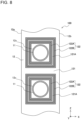
- Fig. 4 is a partial sectional side view showing a fin 12 of the heat exchanger 100 according to Embodiment 1.
- Fig. 4 shows the principal surface of the fin 12.
- Fig. 4 shows cross-sections of heat transfer tubes 11 parallel to the principal surface of the fin 12.
- the heat transfer tubes 11 shown in Fig. 4 are circular tubes and are circular in cross-section. As shown in Fig. 4 , the heat transfer tubes 11 are arranged in a line along the Z direction.
- the fin 12 has a leading edge 12a and a trailing edge 12b. Since air flows in the direction of an arrow R1 of Fig. 4 , the leading edge 12a is disposed further windward than the trailing edge 12b.
- the heat transfer tubes 11 are inserted in through holes 12c formed in the fin 12.
- the outside diameter of each of the heat transfer tubes 11 is equal to the inside diameter of each of the through holes 12c. Accordingly, the heat transfer tubes 11 are in close contact with inner walls of the through holes 12c.
- the principal surface of the fin 12 constitutes a fin base surface 121 that is flat.
- the fin base surface 121 is provided with fin projections 122.
- the fin projections 122 protrude in the Y direction from the fin base surface 121, which is the principal surface of the fin 12.
- the fin projections 122 include inner fin projections 122A provided to separately surround each of the plurality of heat transfer tubes 11.
- the fin projections 122 include outer fin projections 122B provided to separately surround each of the inner fin projections 122A.
- the inner fin projections 122A and the outer fin projections 122B are referred to simply as "fin projections 122" in a case in which there is no particular need to distinguish between them.
- the following description uses each of the nouns "fin projection 122", “inner fin projection 122A ", and “outer fin projection 122B” in either the singular form or the plural form.
- FIG. 4 uses hatching to indicate the fin projections 122 to distinguish them from the fin base surface 121, the fin projections 122 shown in Fig. 4 are not cross-sections.
- Fig. 4 uses solid lines to indicate visible outlines and edge lines of the fin projections 122 in a view of the fin base surface 121 in the Y direction and uses hatching to indicate portions interposed between the visible outlines and the edge lines. This applies to Figs. 8 to 13 , Fig. 15 , Fig. 19 , Fig. 21 , Fig. 23 , Fig. 25 , Fig. 27 , Fig. 29 , and Fig. 31 .
- the fin projections 122 are circular in shape in a view of the principal surface of the fin 12 in the Y direction.
- the heat transfer tubes 11, the inner fin projections 122A, and the outer fin projections 122B are provided in a concentric configuration.
- a relationship among the diameter of each of the heat transfer tubes 11, the diameter of each of the inner fin projections 122A, and the diameter of each of the outer fin projections 122B is expressed as "Diameter of Heat Transfer Tube 11 ⁇ Diameter of Inner Fin Projection 122A ⁇ Diameter of Outer Fin Projection 122B".
- Fig. 5 is a cross-sectional view taken along line A-A in Fig. 4 .
- Fig. 6 is a cross-sectional view taken along line B-B in Fig. 4 .
- the through holes 12c may have fin collars 12d at edges thereof.
- the fin collars 12d protrude in the Y direction from the fin base surface 121, which is the principal surface of the fin 12, along side surfaces of the heat transfer tubes 11 (see Fig. 4 ).
- protruding distal ends of the fin collars 12d have bends, the protruding distal ends do not need to have bends.
- Protruding portions of the fin collars 12d may be linear in shape. It should be noted that although, in Figs. 5 and 6 , the through holes 12c have the fin collars 12d, the through holes 12c do not need to have the fin collars 12d.
- first flat portions 121A In a case in which no first flat portions 121A are provided between the inner fin projections 122A and the outer fin projections 122B, stress concentrates on boundary portions of the inner fin projections 122A and the outer fin projections 122B in the formation of the fin. Concentration of stress in the formation of the fin is avoided by providing the first flat portions 121A.
- the inner fin projections 122A and the outer fin projections 122B are triangular in cross-section. However, the inner fin projections 122A and the outer fin projections 122B do not need to be triangular in cross-section.
- the inner fin projections 122A and the outer fin projections 122B may for example be rectangular, polygonal, or circular in cross-section.
- each of the inner fin projections 122A and the height of each of the outer fin projections 122B are described. Assume that h1 is the height of each of the inner fin projections 122A from the fin base surface 121 and that h2 is the height of each of the outer fin projections 122B from the fin base surface 121. Note here that the height h1 of each of the inner fin projections 122A and the height h2 of each of the outer fin projections 122B may be equal to each other as shown in Figs. 5 and 6 .
- a heat exchanger 100 includes a plurality of fins 12 spaced apart from one another in a first direction Y and a plurality of heat transfer tubes 11 penetrating through the plurality of fins 12, the plurality of heat transfer tubes 11 being spaced apart from one another in a second direction Z crossing the first direction Y.
- Each of the plurality of fins 12 includes a fin base surface 121 that is flat and a plurality of fin projections 122.
- the plurality of fin projections 122 include inner fin projections 122A provided to separately surround each of the plurality of heat transfer tubes 11, the inner fin projections 122A protruding in the first direction Y from the fin base surface 121, and outer fin projections 122B provided to separately surround each of the inner fin projections 122A, the outer fin projections 122B protruding in the first direction Y from the fin base surface 121.
- the inner fin projections 122A and the outer fin projections 122B are provided to surround the heat transfer tubes 11.
- the fin projections 122 have portions extending in the second direction Z of the fin 12. That is, the provision of fin projections 122 having portions along the longitudinal direction of the fin 12 brings about improvement in longitudinal strength of the fin 12. This keeps the fin 12 from bending in the longitudinal direction when worked on, for example when pressed or when stacked. This brings about improvement in producibility of the heat exchanger.
- the provision of the inner fin projections 122A and the outer fin projections 122B around the heat transfer tubes 11 brings about a heat exchange promoting effect that is similar to that which is brought about in a case in which projections are provided in both the longitudinal direction and transverse direction of the fin 12. That is, regardless of whether air flows in from the longitudinal direction or transverse direction of the fin 12, the fin projections 122 are provided in the direction of flow of air. This makes it possible to effectively utilize the inner fin projections 122A and the outer fin projections 122B as heat transfer elements. This results in improvement in heat transfer coefficient on the surface of the fin 12, bringing about improvement in heat transfer performance of the heat exchanger.
- the inner fin projections 122A and the outer fin projections 122B are provided around through holes 12c in which the heat transfer tubes 11 are inserted.
- the material is stretched in a well-balanced manner from all parts of the fin 12, so that distortions in shape due to concentration of stress on the fin base surface 121 can be reduced. This brings about improvement in workability of the fin 12, bringing about improvement in manufacturability of the heat exchanger.
- the plurality of heat transfer tubes 11 are circular in cross-section, and each of the inner fin projections 122A and a corresponding one of the outer fin projections 122B are provided concentrically with a corresponding one of the plurality of heat transfer tubes 11.
- the inner fin projection 122A and the outer fin projection 122B are provided along a circumferential direction of a circular cross-section of the heat transfer tube 11.
- the fin is deformed uniformly in the circumferential direction of the cross-section of the heat transfer tube 11, so that it is hard for stress to concentrate. This brings about improvement in formability of the fin 12, resulting in improvement in manufacturability of the heat exchanger.
- the fin base surface 121 has first flat portions 121A between the inner fin projections 122A and the outer fin projections 122B.
- the first flat portions 121A allows the inner fin projections 122A and the outer fin projections 122B to be provided on the fin 12 without touching each other. This makes it hard for stress to concentrate between the inner fin projections 122A and the outer fin projections 122B in the formation of the fin. This brings about improvement in formability of the fin 12, resulting in improvement in manufacturability of the heat exchanger.
- Fig. 7 is a cross-sectional view showing Modification 1 of a fin 12 of the heat exchanger 100 according to Embodiment 1.
- Fig. 7 shows a portion of Modification 1 that corresponds to a cross-section taken along line B-B in Fig. 4 .
- the fin projections 122 include inner fin projections 122A and outer fin projections 122B.
- the heat exchanger 100 according to Modification 1 is different from Embodiment 1 in relationship between the height h1 of each of the inner fin projections 122A from the fin base surface 121 and the height h2 of each of the outer fin projections 122B from the fin base surface 121.
- the height h1 of each of the inner fin projections 122A and the height h2 of each of the outer fin projections 122B are equal to each other.
- the height h1 of each of the inner fin projections 122A is greater than the height h2 of each of the outer fin projections 122B.
- Other components and workings are not described here, as they are the same as those of Embodiment 1.
- a relationship between the height h1 of each of the inner fin projections 122A and the height h2 of each of the outer fin projections 122B is expressed as h2 ⁇ h1.
- a portion of air colliding with the outer fin projection 122B flows along a slope of the outer fin projection 122B toward an apex of the outer fin projection 122B and passes through the highest part of the outer fin projection 122B.
- the height h2 of the outer fin projection 122B is higher than the height h1 of the inner fin projection 122A, air passing through the highest part of the outer fin projection 122B flows into a space above the highest part of the inner fin projection 122A, that is, a space in which the inner fin projection 122A is not present. Therefore, a portion of air colliding with the outer fin projection 122B does not collide with the inner fin projection 122A. Meanwhile, in a case in which the height h2 of the outer fin projection 122B and the height h1 of the inner fin projection 122A are equal to each other, it is easy for air colliding with the outer fin projection 122B to collide with the inner fin projection 122A.
- Embodiment 1 or Modification 1 in which the relationship between the height h1 of the inner fin projection 122A and the height h2 of the outer fin projection 122B is expressed as h2 ⁇ h1, more air flows into the gap between the outer fin projection 122B and the inner fin projection 122A and the gap between the inner fin projection 122A and the heat transfer tube 11. This increases the area of contact of air with the outer fin projection 122B and the inner fin projection 122A, bringing about improvement in heat transfer coefficient on the surface of the fin 12 and improvement in heat transfer performance of the heat exchanger.
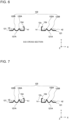
- Fig. 8 is a partial sectional side view showing Modification 2 of a fin 12 of the heat exchanger 100 according to Embodiment 1.
- Fig. 8 shows the surface of the fin 12 and cross-sections of heat transfer tubes 11 parallel to the principal surface of the fin 12.
- the fin projections 122 include inner fin projections 122A and outer fin projections 122B.
- the inner fin projections 122A and the outer fin projections 122B in Modification 2 of Embodiment 1 are provided in rectangular shapes to surround the heat transfer tubes 11. Differences from Embodiment 1 lie in the shapes of the inner fin projections 122A and the outer fin projections 122B. Other components and workings are not described here, as they are the same as those of Embodiment 1.
- the fin projections 122 have portions linearly extending in the Z direction of the fin 12. That is, the provision of fin projections 122 having linear portions along the longitudinal direction of the fin 12 brings about further improvement in longitudinal strength of the fin 12. As in the case of Embodiment 1, this keeps the fin 12 from bending in the longitudinal direction when worked on, for example when pressed or when stacked. This brings about improvement in producibility of the heat exchanger.
- Fig. 9 is a partial sectional side view showing Modification 3 of a fin 12 of the heat exchanger 100 according to Embodiment 1.
- Fig. 9 shows the surface of the fin 12 and cross-sections of heat transfer tubes 11 parallel to the principal surface of the fin 12.
- the fin projections 122 include inner fin projections 122A and outer fin projections 122B.
- the inner fin projections 122A and the outer fin projections 122B in Modification 3 of Embodiment 1 are provided in elliptical shapes to surround the heat transfer tubes 11. Differences from Embodiment 1 lie in the shapes of the inner fin projections 122A and the outer fin projections 122B. Other components and workings are not described here, as they are the same as those of Embodiment 1.
- the inner fin projections 122A and the outer fin projections 122B are larger in diameter in the X direction than in the Z direction. That is, the fin projections 122 have portions elongated in the transverse direction of the fin 12, that is, the direction in which air flows in. This makes it easy for air to make contact with the fin projections 122. As in the case of Embodiment 1, this results in improvement in heat transfer coefficient on the surface of the fin 12.
- Fig. 10 is a cross-sectional view showing Modification 4 of a fin 12 of the heat exchanger 100 according to Embodiment 1.
- Fig. 10 shows the surface of the fin 12 and cross-sections of heat transfer tubes 11 parallel to the principal surface of the fin 12.
- the fin projections 122 include inner fin projections 122A and outer fin projections 122B.
- the inner fin projections 122A and the outer fin projections 122B are different in shape from each other.
- each of the inner fin projections 122A in Modification 4 is provided concentrically with a corresponding one of the heat transfer tubes 11.
- the outer fin projections 122B in Modification 4 are provided in elliptical shapes to surround the heat transfer tubes 11. Differences from Embodiment 1 lie in the shapes of the outer fin projections 122B.
- Other components and workings are not described here, as they are the same as those of Embodiment 1.
- the inner fin projections 122A are in the shapes of circles provided concentrically with the heat transfer tubes 11. Meanwhile, the outer fin projections 122B are in the shapes of ellipses. As shown in Fig. 10 , the outer fin projections 122B are larger in diameter in the X direction than in the Z direction. That is, the outer fin projections 122B have portions elongated in the transverse direction of the fin 12, that is, the direction in which air flows in. This makes it easy for air to make contact with the fin projections 122. As in the case of Embodiment 1, this results in improvement in heat transfer coefficient on the surface of the fin 12.
- Fig. 11 is a cross-sectional view showing Modification 5 of a fin 12 of the heat exchanger 100 according to Embodiment 1.
- Fig. 11 shows the surface of the fin 12 and cross-sections of heat transfer tubes 11 parallel to the principal surface of the fin 12.
- the fin projections 122 include inner fin projections 122A and outer fin projections 122B.
- additional fin projections 122D are provided to surround the outer fin projections 122B. Differences between Embodiment 1 and Modification 5 lie in these additional fin projections 122D. Other components and workings are not described here, as they are the same as those of Embodiment 1.
- one or more additional fin projections 122D are provided concentrically with the heat transfer tubes 11 to surround the outer fin projections 122B.
- the fin projections 122 have portions elongated in the second direction Z of the fin 12. That is, the provision of fin projections 122 having portions along the longitudinal direction of the fin 12 brings about improvement in longitudinal strength of the fin 12. This keeps the fin from bending in the longitudinal direction when worked on, for example when pressed or when stacked. This brings about improvement in producibility of the heat exchanger.
- the provision of the additional fin projections 122D around the outer fin projections 122B brings about an effect that is similar to that which is brought about in a case in which projections are added in both the longitudinal direction and transverse direction of the fin 12. That is, regardless of whether air flows in from the longitudinal direction or transverse direction of the fin 12, projections are added in the direction of flow of air.
- This makes it possible to effectively utilize the additional fin projections 122D as heat transfer elements. Further, this makes it easier for inflow air to make contact with the additional fin projections 122D, thus bringing about improvement in heat transfer coefficient and improvement in heat transfer performance of the heat exchanger.
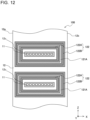
- Fig. 12 is a partial sectional side view showing Modification 6 of a fin 12 of the heat exchanger 100 according to Embodiment 1.
- Fig. 12 shows the surface of the fin 12 and cross-sections of heat transfer tubes 11 parallel to the principal surface of the fin 12.
- the fin projections 122 include inner fin projections 122A and outer fin projections 122B.
- the heat transfer tubes 11 are constituted by flat tubes. Further, the inner fin projections 122A and the outer fin projections 122B are provided in rectangular shapes to surround the heat transfer tubes 11. Differences between Embodiment 1 and Modification 6 lie in the shapes of the heat transfer tubes 11, the inner fin projections 122A, and the outer fin projections 122B. Other components and workings are not described here, as they are the same as those of Embodiment 1.
- the fin projections 122 have portions linearly extending in the Z direction of the fin 12. That is, the provision of fin projections 122 having linear portions along the longitudinal direction of the fin 12 brings about further improvement in longitudinal strength of the fin 12. As in the case of Embodiment 1, this keeps the fin from bending in the longitudinal direction when worked on, for example when pressed or when stacked. This brings about improvement in producibility of the heat exchanger.
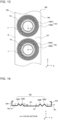
- Fig. 13 is a partial sectional side view showing Modification 7 of a fin 12 of the heat exchanger 100 according to Embodiment 1.
- Fig. 13 shows the surface of the fin 12 and cross-sections of heat transfer tubes 11 parallel to the principal surface of the fin 12.
- the fin projections 122 include inner fin projections 122A and outer fin projections 122B.
- Fig. 14 is a cross-sectional view taken along line A-A in Fig. 13 .
- the fin base surface 121 has no first flat portions 121A. This makes it impossible to bring about an effect of avoiding concentration of stress between the inner fin projections 122A and the outer fin projections 122B in the formation of the fin. However, in terms of improvement in longitudinal strength of the fin 12 and improvement in heat transfer coefficient of the surface of the fin 12, Modification 7 brings about an effect that is similar to that of Embodiment 1.
- Embodiment 1 and Modifications 1 to 7 thereof the shapes of the inner fin projections 122A and the outer fin projections 122B are described with reference to Fig. 4 and Figs. 8 to 14 .
- the plurality of heat transfer tubes 11 are surrounded by inner fin projections 122A of the same shape.
- inner fin projections 122A having different shapes may be provided separately for each of the heat transfer tubes 11.
- the plurality of inner fin projections 122A are surrounded by outer fin projections 122B of the same shape.
- outer fin projections 122B having different shapes may be provided separately for each of the heat transfer tubes 11.
- a basic configuration of a heat exchanger 100 according to Embodiment 2 is not described here, as it is the same as that of the heat exchanger 100 of Embodiment 1.
- a basic configuration of a refrigeration cycle apparatus 1 according to Embodiment 2 is not described here, as it is the same as that of the refrigeration cycle apparatus 1 of Embodiment 1.
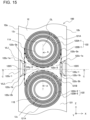
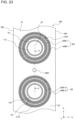
- Fig. 15 is a partial sectional side view showing a fin 12 of the heat exchanger 100 according to Embodiment 2.
- Fig. 15 shows the principal surface of the fin 12 and cross-sections of heat transfer tubes 11.
- the cross-sections of the heat transfer tubes 11 shown in Fig. 15 are cross-sections parallel to the principal surface of the fin 12.
- the heat transfer tubes 11 are arranged in a line along a column-wise direction parallel with the longitudinal direction of the fin 12.
- the fin 12 has a leading edge 12a and a trailing edge 12b.
- first heat transfer tube 11A the upper heat transfer tube 11 as seen from the front of the surface of paper of Fig. 15
- second heat transfer tube 11B the lower heat transfer tube 11 as seen from the front of the surface of paper of Fig. 15
- the principal surface of the fin 12 constitutes a fin base surface 121 that is flat.
- the inner fin projections 122A and the outer fin projections 122B are provided to protrude in the Y direction from the fin base surface 121.
- an inner fin projection 122A provided to surround the first heat transfer tube 11A is called “first inner fin projection 122A-1”.
- an outer fin projection 122B provided to surround the first inner fin projection 122A-1 is called “first outer fin projection 122B-1”.
- an inner fin projection 122A provided to surround the second heat transfer tube 11B is called “second inner fin projection 122A-2”.
- an outer fin projection 122B provided to surround the second inner fin projection 122A-2 is called “second outer fin projection 122B-2”.
- Fig. 16 is a cross-sectional view taken along line A-A in Fig. 15 .
- Fig. 17 is a cross-sectional view taken along line C-C in Fig. 15 .
- the first inner fin projection 122A-1 and the second inner fin projection 122A-2 are referred to simply as “inner fin projections 122A” in a case in which there is no particular need to distinguish between them.
- the first outer fin projection 122B-1 and the second outer fin projection 122B-2 are referred to simply as "outer fin projections 122B" in a case in which there is no particular need to distinguish between them.
- first outer fin projection 122B-1 and the second outer fin projection 122B-2 There is a gap between the first outer fin projection 122B-1 and the second outer fin projection 122B-2.
- a portion of the gap between the first outer fin projection 122B-1 and the second outer fin projection 122B-2 surrounded by thick dot-and-dash lines in Fig. 15 is called "second flat portion 121B". That is, when viewed from the front of the surface of paper of Fig. 15 , the second flat portion 121B is a portion of the fin base surface 121 interposed between a lower semicircular portion of the first outer fin projection 122B-1 and an upper semicircular portion of the second outer fin projection 122B-2. Further, in Fig.
- a linear portion between the first outer fin projection 122B-1 and the second outer fin projection 122B-2 corresponds to the second flat portion 121 B.
- stress concentrates on boundary portions of the first outer fin projection 122B-1 and the second outer fin projection 122B-2 in the formation of the fin. Concentration of stress in the formation of the fin is avoided by providing the second flat portion 121B.
- the fin base surface 121 is provided with intermediate fin projections 122C.
- the intermediate fin projections 122C protrude in the Y direction from the portion of the fin base surface 121 situated between the first outer fin projection 122B-1 and the second outer fin projection 122B-2. That is, in Embodiment 2, the fin projections 122 include the inner fin projections 122A, the outer fin projections 122B, and the intermediate fin projections 122C. As shown in Figs. 16 and 17 , the inner fin projections 122A, the outer fin projections 122B, and the intermediate fin projections 122C protrude in the same direction from the fin base surface 121 in the Y direction.
- a basic configuration of the fin 12 according to Embodiment 2 is not described, as it is identical to that of Embodiment 1 except for the intermediate fin projections 122C. It should be noted that the number of intermediate fin projections 122C is not limited to 2, although two intermediate fin projections 122C are provided in Fig. 15 . One intermediate fin projection 122C may be provided, or three or more intermediate fin projections 122C may be provided.
- the intermediate fin projections 122C are provided in a space between the first outer fin projection 122B-1 and the second outer fin projection 122B-2 in the longitudinal direction of the fin 12. However, the intermediate fin projections 122C do not need to be wholly located in the space between the first outer fin projection 122B-1 and the second outer fin projection 122B-2. As shown in Fig. 15 , the intermediate fin projections 122C need only be partially located in the space between the first outer fin projection 122B-1 and the second outer fin projection 122B-2. In the present disclosure, the space between the first outer fin projection 122B-1 and the second outer fin projection 122B-2 refers to the portion of the fin base surface 121 that corresponds to the second flat portion 121B.
- a straight line passing through the center of the first heat transfer tube 11A and the center of the second heat transfer tube 11B along the Z direction is called "center line CL".
- a dot-and-dash line indicating the A-A cross-section corresponds to the center line CL.
- the intermediate fin projections 122C are provided at positions not crossing the center line CL.
- Each of the intermediate fin projections 122C includes a first raised portion 122c-1 and a second raised portion 122c-2 that rise from the fin base surface 121.
- the first raised portion 122c-1 and the second raised portion 122c-2 extend parallel along the Z direction of the fin 12.
- the first raised portion 122c-1 is greater in length than the second raised portion 122c-2.
- the distance between the first raised portion 122c-1 and the center line CL is longer than the distance between the second raised portion 122c-2 and the center line CL.
- the first raised portion 122c-1 has two ends in the Z direction. One of the two ends of the first raised portion 122c-1 that is close to the first outer fin projection 122B-1 is called “first end 122c-1a”. Further, one of the two ends of the first raised portion 122c-1that is close to the second outer fin projection 122B-2 is called “second end 122c-1b”. That is, the first raised portion 122c-1 has the first end 122c-1a and the second end 122c-1b. Further, the second raised portion 122c-2 has two ends in the Z direction. One of the two ends of the second raised portion 122c-2 that is close to the first outer fin projection 122B-1 is called “first end 122c-2a”.
- second end 122c-2b one of the two ends of the second raised portion 122c-2 that is close to the second outer fin projection 122B-2. That is, the second raised portion 122c-2 has the first end 122c-2a and the second end 122c-2b.
- first virtual line VL1 is a virtual straight line passing through the first end 122c-1a of the first raised portion 122c-1 and the first end 122c-2a of the second raised portion 122c-2.
- second virtual line VL2 is herein a virtual straight line passing through the second end 122c-1b of the first raised portion 122c-1 and the second end 122c-2b of the second raised portion 122c-2. As shown in Fig.
- the first virtual line VL1 does not cross the first outer fin projection 122B-1. Therefore, a given gap is formed between a portion of the intermediate fin projection 122C connecting the first end 122c-1a of the first raised portion 122c-1 with the first end 122c-2a of the second raised portion 122c-2 and the first outer fin projection 122B-1. Further, the second virtual line VL2 does not cross the second outer fin projection 122B-2. Therefore, a given gap is formed between a portion of the intermediate fin projection 122C connecting the second end 122c-1b of the first raised portion 122c-1 with the second end 122-2b of the second raised portion 122c-2 and the second outer fin projection 122B-2.
- the given gaps here are portions of the fin base surface 121 and flat regions having areas for avoiding concentration of stress around the intermediate fin projection 122C in the formation of the fin. If the areas of the gaps between the intermediate fin projection 122C and the outer fin projections 122B are small, concentration of stress around the intermediate fin projection 122C in the formation of the fin cannot be avoided.
- the intermediate fin projection 122C is provided so that the first virtual line VL1 does not cross the first outer fin projection 122B-1. This makes it possible to secure a flat region on the fin base surface 121 between the intermediate fin projection 122C and the first outer fin projection 122B-1 that can avoid concentration of stress in the formation of the fin.
- the intermediate fin projection 122C is provided so that the second virtual line VL2 does not cross the second outer fin projection 122B-2. This makes it possible to secure a flat region on the fin base surface 121 between the intermediate fin projection 122C and the second outer fin projection 122B-2 that can avoid concentration of stress in the formation of the fin.
- the plurality of heat transfer tubes 11 include a first heat transfer tube 11A and a second heat transfer tube 11B that are adjacent to each other in the second direction Z.
- the inner fin projections 122A include a first inner fin projection 122A-1 provided to surround the first heat transfer tube 11A and a second inner fin projection 122A-2 provided to surround the second heat transfer tube 11B.
- the outer fin projections 122B include a first outer fin projection 122B-1 provided to surround the first inner fin projection 122A-1 and a second outer fin projection 122B-2 provided to surround the second inner fin projection 122A-2.
- the fin base surface 121 has a second flat portion 121B between the first outer fin projection 122B-1 and the second outer fin projection 122B-2.
- the second flat portion 121B allows the first outer fin projections 122B-1 and the second outer fin projection 122B-2 to be provided on the fin 12 without touching each other. This prevents stress from concentrating between the first outer fin projections 122B-1 and the second outer fin projection 122B-2 in the formation of the fin. This brings about improvement in formability of the fin 12, resulting in improvement in manufacturability of the heat exchanger.
- the plurality of fin projections 122 include an intermediate fin projection 122C protruding in the first direction Y from the fin base surface 121, and the intermediate fin projection 122C is provided so that at least part of the intermediate fin projection 122C is located between the first outer fin projection 122B-1 and the second outer fin projection 122B-2 in the second direction Z.
- providing the intermediate fin projection 122C makes it easy for air to make contact with the surface of the fin 12. This results in further improvement in heat transfer coefficient on the surface of the fin 12. Further, locating part of the intermediate fin projection 122C between the first outer fin projection 122B-1 and the second outer fin projection 122B-2 results in reducing a region in which no fin projections 122 are present in the longitudinal direction of the fin 12. This brings about further improvement in longitudinal strength of the fin 12.
- the intermediate fin projection 122C is provided at a position not crossing a center line CL passing through a center of the first heat transfer tube 11A and a center of the second heat transfer tube 11B along the second direction Z. Note here that in the second direction Z of the fin 12, a length between the first outer fin projection 122B-1 and the second outer fin projection 122B-2 is shortest in a portion through which the center line CL passes.
- the intermediate fin projection 122C is provided not at a position where the first outer fin projection 122B-1 and the second outer fin projection 122B-2 are closest to each other but at a place where there is a relatively large gap between the first outer fin projection 122B-1 and the second outer fin projection 122B-2.
- the intermediate fin projection 122C includes a first raised portion 122c-1 extending in the second direction Z, the first raised portion 122c-1 being raised from the fin base surface 121, and a second raised portion 122c-2 extending parallel to the first raised portion 122c-1, the second raised portion 122c-2 raised from the fin base surface 121.
- the first raised portion 122c-1 is greater in length than the second raised portion 122c-2.
- a distance between the first raised portion 122c-1 and the center line CL is longer than a distance between the second raised portion 122c-2 and the center line CL.
- the first raised portion 122c-1 includes a first end 122c-1a provided adjacent to the first outer fin projection 122B-1 and a second end 122c-1b provided adjacent to the second outer fin projection 122B-2.
- the second raised portion 122c-2 includes a first end 122c-2a provided adjacent to the first outer fin projection 122B-1 and a second end 122c-2b provided adjacent to the second outer fin projection 122B-2.
- a first virtual line VL1 passing through the first end 122c-1a of the first raised portion 122c-1 and the first end 122c-2a of the second raised portion 122c-2 does not cross the first outer fin projection 122B-1.
- a second virtual line VL2 passing through the second end 122c-1b of the first raised portion 122c-1 and the second end 122c-2b of the second raised portion 122c-2 does not cross the second outer fin projection 122B-2.
- This configuration makes it possible to secure flat regions on the fin base surface 121 between the intermediate fin projection 122C and the outer fin projections 122B for avoiding concentration of stress between the intermediate fin projection 122C and the outer fin projections 122B in the formation of the fin. This brings about further improvement in formability of the fin 12.
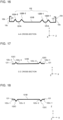
- Fig. 18 is a cross-sectional view showing Modification 1 of a fin 12 of the heat exchanger 100 according to Embodiment 2.
- Fig. 18 shows a portion of Modification 1 that corresponds to a cross-section taken along line C-C in Fig. 15 .
- the fin 12 includes intermediate fin projections 122C.
- a direction in which the inner fin projections 122A protrude from the fin base surface 121 and a direction in which the intermediate fin projection 122C protrudes from the fin base surface 121 are opposite to each other. Accordingly, the inner fin projections 122A are not located in a wake flow portion of the intermediate fin projection 122C. That is, the inner fin projections 122A are not affected by a dead water region of the intermediate fin projection 122C. This can result in maximized utilization of the inner fin projections 122A for heat exchange, bringing about improvement in heat transfer coefficient on the surface of the fin 12.
- a direction in which the outer fin projections 122B protrude from the fin base surface 121 is identical to a direction in which the inner fin projections 122A protrude. That is, the outer fin projections 122B too are not located in a wake flow portion of the intermediate fin projection 122C and are therefore not affected by a dead water region of the intermediate fin projection 122C. This can result in maximized utilization of the outer fin projections 122B for heat exchange, bringing about further improvement in heat transfer coefficient on the surface of the fin 12.
- the center of gravity of the fin 12 is close to the fin base surface 121 in the Y direction, as the inner fin projections 122A and the intermediate fin projection 122C protrude in directions opposite to each other. This brings about improvement in strength of the fin 12.
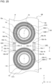
- Fig. 19 is a partial sectional side view showing Modification 2 of a fin 12 of the heat exchanger 100 according to Embodiment 2.
- Fig. 19 shows the surface of the fin 12 and cross-sections of heat transfer tubes 11 parallel to the principal surface of the fin 12.
- the fin projections 122 include an intermediate fin projection 122C.
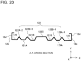
- Fig. 20 is a cross-sectional view taken along line A-A in Fig. 19 .
- the intermediate fin projection 122C is provided between the first outer fin projection 122B-1 and the second outer fin projection 122B-2 to overlap the center line CL.
- the intermediate fin projection 122C when viewed from the Y direction, has the shape of an oblong whose long sides extend in the Z direction. Differences between Modification 2 and Embodiment 2 lie in the position of the intermediate fin projection 122C and the shape of the intermediate fin projection 122C.
- Other components and workings are not described here, as they are the same as those of Embodiment 1.
- the intermediate fin projection 122C overlaps the center line CL between the first outer fin projection 122B-1 and the second outer fin projection 122B-2.
- the distance between the first raised portion 122c-1 and the center line CL and the distance between the second raised portion 122c-2 and the center line CL are equal to each other.
- the first raised portion 122c-1 and the second raised portion 122c-2 are equal in length to each other.
- the first raised portion 122c-1 is the left long side as seen from the front of the surface of paper
- the second raised portion 122c-2 is the right long side as seen from the front of the surface of paper.
- the intermediate fin projection 122c is located in a portion in which the distance between the first outer fin projection 122B-1 and the second outer fin projection 122B-2 is shortest in the Z direction.
- providing an intermediate fin projection 122C as in the case of Modification 2 brings about improvement in longitudinal strength of the fin 12 and improvement in heat transfer coefficient of the surface of the fin 12.
- Fig. 21 is a partial sectional side view showing Modification 3 of a fin 12 of the heat exchanger 100 according to Embodiment 2.
- Fig. 21 shows the surface of the fin 12 and cross-sections of heat transfer tubes 11 parallel to the principal surface of the fin 12.
- the fin projections 122 include an intermediate fin projection 122C.
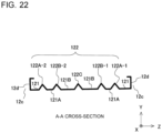
- Fig. 22 is a cross-sectional view taken along line A-A in Fig. 21 .
- the intermediate fin projection 122C is provided between the first outer fin projection 122B-1 and the second outer fin projection 122B-2 to cross the center line CL.
- the intermediate fin projection 122C has a portion elongated in the X direction.
- the intermediate fin projection 122C in the X direction, is larger in diameter than the first outer fin projection 122B-1 and the second outer fin projection 122B-2.
- the intermediate fin projection 122C may be larger in diameter than or equal in diameter to the first outer fin projection 122B-1 and the second outer fin projection 122B-2.
- Fig. 23 is a partial sectional side view showing Modification 4 of a fin 12 of the heat exchanger 100 according to Embodiment 2.
- Fig. 23 shows the surface of the fin 12 and cross-sections of heat transfer tubes 11 parallel to the principal surface of the fin 12.
- the fin projections 122 include an intermediate fin projection 122C.
- Fig. 24 is a cross-sectional view taken along line A-A in Fig. 23 .
- the intermediate fin projection 122C is provided between the first outer fin projection 122B-1 and the second outer fin projection 122B-2 to overlap the center line CL.
- the intermediate fin projection 122C has a circular shape.
- the intermediate fin projection 122C protrudes in a semispherical shape from the fin base surface 121.
- Differences between Modification 4 and Embodiment 2 lie in the position of the intermediate fin projection 122C and the shape of the intermediate fin projection 122C.
- Other components and workings are not described here, as they are the same as those of Embodiment 2.
- the intermediate fin projection 122C overlaps the center line CL between the first outer fin projection 122B-1 and the second outer fin projection 122B-2.
- a portion of the intermediate fin projection 122C in Modification 4 elongated along the longitudinal direction of the fin 12 is not as long as portions of the intermediate fin projections 122C in Embodiment 2 elongated along the longitudinal direction of the fin 12.
- providing the intermediate fin projection 122C brings about improvement in longitudinal strength of the fin 12 and improvement in heat transfer coefficient of the surface of the fin 12.
- Fig. 25 is a partial sectional side view showing Modification 5 of a fin 12 of the heat exchanger 100 according to Embodiment 2.
- Fig. 25 shows the surface of the fin 12 and cross-sections of heat transfer tubes 11 parallel to the principal surface of the fin 12.
- the fin projections 122 include intermediate fin projections 122C.
- Fig. 26 is a cross-sectional view taken along line C-C in Fig. 25 .
- each of the intermediate fin projections 122C is configured such that the first raised portion 122c-1 and the second raised portion 122c-2 are equal in length to each other.
- the first raised portion 122c-1 is greater in length than the second raised portion 122c-2.
- Differences between Modification 5 and Embodiment 2 lie in a relationship in length between the first raised portion 122c-1 and the second raised portion 122c-2.
- Other components and workings are not described here, as they are the same as those of Embodiment 2.
- the first virtual line VL1 crosses the first outer fin projection 122B-1. Further, the second virtual line VL2 crosses the second outer fin projection 122B-2.
- intermediate fin projections 122C shaped as shown in Modification 5 may be provided. Providing the intermediate fin projections 122C of Modification 5 brings about improvement in longitudinal strength of the fin 12 and improvement in heat transfer coefficient of the surface of the fin 12.
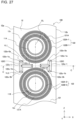
- Fig. 27 is a partial sectional side view showing Modification 6 of a fin 12 of the heat exchanger 100 according to Embodiment 2.
- Fig. 27 shows the surface of the fin 12 and cross-sections of heat transfer tubes 11 parallel to the principal surface of the fin 12.
- the fin projections 122 include intermediate fin projections 122C.
- Fig. 28 is a cross-sectional view taken along line C-C in Fig. 27 .
- the intermediate fin projections 122C when viewed from Y direction, the intermediate fin projections 122C have T shapes laid down 90 degrees. Therefore, as shown in Fig. 28 , the intermediate fin projections 122C have portions elongated in the X direction. Differences between Modification 6 and Embodiment 2 lie in the shapes of the intermediate fin projections 122C. Other components and workings are not described here, as they are the same as those of Embodiment 2.
- the first virtual line VL1 crosses the first outer fin projection 122B-1. Further, the second virtual line VL2 crosses the second outer fin projection 122B-2. Furthermore, portions of the intermediate fin projections 122C elongated in the X direction are located between the first outer fin projection 122B-1 and the second outer fin projection 122B-2.
- Each of the intermediate fin projections 12C of Modification 6 includes a portion linearly extending along the longitudinal direction (Z direction) of the fin 12 and a portion linearly extending along the transverse direction (X direction). Providing the intermediate fin projections 122C of Modification 6 brings about longitudinal strength of the fin 12.
- the intermediate fin projections 122C make it easy for air to make contact with the surface of the fin 12, as the intermediate fin projections 122C have portions elongated in the X direction, in which air flows in. Therefore, Modification 6 can bring about further improvement in heat transfer coefficient on the surface of the fin 12 than Embodiment 2.
- Fig. 29 is a partial sectional side view showing Modification 7 of a fin 12 of the heat exchanger 100 according to Embodiment 2.
- Fig. 29 shows the surface of the fin 12 and cross-sections of heat transfer tubes 11 parallel to the principal surface of the fin 12.
- the fin projections 122 include intermediate fin projections 122C.
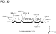
- Fig. 30 is a cross-sectional view taken along line C-C in Fig. 29 .
- the intermediate fin projections 122C include first intermediate fin projections 122C-1 and second intermediate fin projections 122C-2.
- the first intermediate fin projections 122C-1 and the second intermediate fin projections 122C-2 have the shapes of oblongs whose long sides extend in the Z direction when viewed from the Y direction.
- Differences between Modification 7 and Embodiment 2 lie in that in Modification 7, the intermediate fin projections 122C include the first intermediate fin projections 122C-1 and the second intermediate fin projections 122C-2.
- the shapes of the intermediate fin projections 122C in Embodiment 2 and the shapes of the first intermediate fin projections 122C-1 and the second intermediate fin projections 122C-2 in Modification 7 are different from each other. Other components and workings are not described here, as they are the same as those of Embodiment 2.
- first intermediate fin projections 122C-1 and the second intermediate fin projections 122C-2 are referred to simply as “intermediate fin projections 122C” in a case in which there is no particular need to distinguish between them.
- the following description uses the noun “intermediate fin projection 122C” in either the singular form or the plural form.
- first raised portions 122c-1 too, the first raised portions 122c1-1 of the first intermediate fin projections 122C-1 and the first raised portions 122c2-1 of the second intermediate fin projections 122C-2 are referred to simply as "first raised portions 122c-1" in a case in which there is no particular need to distinguish between them.
- second raised portions 122c-2 the second raised portions 122c1-2 of the first intermediate fin projections 122C-1 and the first raised portions 122c2-2 of the second intermediate fin projections 122C-2 are referred to simply as “second raised portions 122c-2" in a case in which there is no particular need to distinguish between them.
- the following description uses each of the nouns "first raised portion 122c-1" and “second raised portion 122c-2" in either the singular form or the plural form.
- the first intermediate fin projections 122C-1 and the second intermediate fin projections 122C-2 are described with reference to Fig. 29 .
- Each of the first intermediate fin projections 122C-1 is configured such that the first raised portion 122c1-1 and the second raised portion 122c1-2 are equal in length to each other.
- each of the second intermediate fin projections 122C-2 is configured such that the first raised portion 122c2-1 and the second raised portion 122c2-2 are equal in length to each other. It should be noted that differences between the intermediate fin projections 122C in Embodiment 2 and the intermediate fin projections 122C in Modification 7 lie in relationships in length between the first raised portions 122c-1 and the second raised portions 122c-2.
- first intermediate fin projections 122C-1 is not limited to 2, although two first intermediate fin projections 122C-1 are provided in Fig. 29 .
- One first intermediate fin projection 122C-1 may be provided, or three or more first intermediate fin projections 122C-1 may be provided.
- second intermediate fin projections 122C-2 is not limited to 2, although two second intermediate fin projections 122C-2 are provided in Fig. 29 .
- One second intermediate fin projection 122C-2 may be provided, or three or more second intermediate fin projections 122C-2 may be provided.
- each of the first intermediate fin projections 122C-1 and the center line CL is longer than the distance between each of the second intermediate fin projections 122C-2 and the center line CL.
- the first raised portions 122c1-1 of the first intermediate fin projections 122C-1 are greater in length than the first raised portions 122c2-1 of the second intermediate fin projections 122C-2. That is, the first intermediate fin projections 122C-1 are larger than the second intermediate fin projections 122C-2.
- the first intermediate fin projections 122C-1 and the second intermediate fin projections 122C-2 which linearly extend along the longitudinal direction of the fin 12, are arranged along the transverse direction of the fin.
- providing the first intermediate fin projections 122C-1 and the second intermediate fin projections 122C-2 brings about improvement in longitudinal strength of the fin 12 and improvement in heat transfer coefficient of the surface of the fin 12.
- Fig. 31 is a partial sectional side view showing Modification 8 of a fin 12 of the heat exchanger 100 according to Embodiment 2.
- Fig. 31 shows the surface of the fin 12 and cross-sections of heat transfer tubes 11 parallel to the principal surface of the fin 12.
- the fin projections 122 include intermediate fin projections 122C.
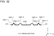
- Fig. 32 is a cross-sectional view taken along line C-C in Fig. 31 .
- the intermediate fin projections 122C include first intermediate fin projections 122C-1 and second intermediate fin projections 122C-2.
- the first intermediate fin projections 122C-1 have the shapes of oblongs whose long sides extend in the Z direction when viewed from the Y direction.
- the second intermediate fin projections 122C-2 have the shapes of circles when viewed from the Y direction.
- Differences between Modification 8 and Embodiment 2 lie in that in Modification 8, the intermediate fin projections 122C include the first intermediate fin projections 122C-1 and the second intermediate fin projections 122C-2.
- the shapes of the intermediate fin projections 122C in Embodiment 2 and the shapes of the first intermediate fin projections 122C-1 and the second intermediate fin projections 122C-2 in Modification 8 are different from each other. Other components and workings are not described here, as they are the same as those of Embodiment 2.
- the first intermediate fin projections 122C-1 and the second intermediate fin projections 122C-2 are described with reference to Fig. 31 .
- Each of the first intermediate fin projections 122C-1 is configured such that the first raised portion 122c1-1 and the second raised portion 122c1-2 are equal in length to each other.
- the distance between each of the first intermediate fin projections 122C-1 and the center line CL is longer than the distance between each of the second intermediate fin projections 122C-2 and the center line CL.
- differences between the intermediate fin projections 122C in Embodiment 2 and the intermediate fin projections 122C in Modification 8 lie in relationships in length between the first raised portions 122c-1 and the second raised portions 122c-2.
- first intermediate fin projections 122C-1 is not limited to 2, although two first intermediate fin projections 122C-1 are provided in Fig. 31 .
- One first intermediate fin projection 122C-1 may be provided, or three or more first intermediate fin projections 122C-1 may be provided.
- second intermediate fin projections 122C-2 is not limited to 2, although two second intermediate fin projections 122C-2 are provided in Fig. 31 .
- One second intermediate fin projection 122C-2 may be provided, or three or more second intermediate fin projections 122C-2 may be provided.
- the first intermediate fin projections 122C-1 which linearly extend along the longitudinal direction of the fin 12, are provided. Further, at positions where the distance between the first outer fin projection 122B-1 and the second outer fin projection 122B2 is relatively short, the circular second intermediate fin projections 122C-2, whose lengths along the longitudinal direction of the fin 12 are relatively short, are provided to reduce the area of a flat portion of the fin 12.
- providing the first intermediate fin projections 122C-1 and the second intermediate fin projections 122C-2 brings about improvement in longitudinal strength of the fin 12 and improvement in heat transfer coefficient of the surface of the fin 12.
- the heat exchanger 100 of any of Embodiment 1, Embodiment 2, and the modifications thereof can be provided in the refrigeration cycle apparatus 1 shown in Fig. 3 .
- the fin projections 122 provided on each of the fins 12 of the heat exchanger 100 brings about an increase in longitudinal direction of the fin 12 and improvement in formability of the fin. This brings about improvement in manufacturability of the heat exchanger 100, resulting in improvement in manufacturability of the refrigeration cycle apparatus 1 as a whole.
- the fin projections 122 provided on each of the fins 12 of the heat exchanger 100 make it easy for air to make contact with the surface of the fin 12. This brings about improvement in heat transfer coefficient of the heat exchanger 100, resulting in improvement in energy efficiency of the refrigeration cycle apparatus 1 as a whole.
- Embodiment 1 has described Embodiment 1, Embodiment 2, and the modifications thereof
- the heat exchanger 100 and the refrigeration cycle apparatus 1 are not limited to Embodiment 1, Embodiment 2, or the modifications thereof and may be altered or applied in various ways without departing from the scope of the disclosure.
- Embodiment 1, Embodiment 2, and the modifications thereof may be combined with one another to such an extent as not to impair the functions or structures of the embodiments or the modifications.
Landscapes
- Engineering & Computer Science (AREA)
- Physics & Mathematics (AREA)
- Thermal Sciences (AREA)
- Mechanical Engineering (AREA)
- General Engineering & Computer Science (AREA)
- Geometry (AREA)
- Heat-Exchange Devices With Radiators And Conduit Assemblies (AREA)
Abstract
Description
- The present disclosure relates to a heat exchanger and a refrigeration cycle apparatus including the same.
- There has been known a technique for improving the heat transfer performance of a fin-and-tube heat exchanger by providing projections on a fin surface to control the direction of flow of air.
- For example, in a heat exchanger described in
Patent Literature 1, projections for preventing airflow separation are provided around each heat transfer tube to narrow a dead water region in a wake flow portion of the heat transfer tube to bring about improvement in heat transfer performance. The term "dead water region" here means a region into which air does not flow and where there is a decrease in heat transfer coefficient. InPatent Literature 1, a collision of an airflow with the projections around the heat transfer tube causes air to flow into the wake flow portion of the heat transfer tube, thus narrowing the dead water region in the wake flow portion of the heat transfer tube. - Patent Literature 1:
Japanese Unexamined Patent Application Publication No. 58-158496 - In
Patent Literature 1, the projections are provided at positions at an angle of ±70 degrees to ±80 degrees to a stagnation point directed toward the center of the heat transfer tube, with the result that the projections are sparsely provided around the heat transfer tube. For this reason, inPatent Literature 1, it is hard to secure, around the heat transfer tube, a region in which to provide additional projections for improving the strength of each fin. The incapability of providing additional projections for improving the strength of the fins causes the fin to bend in a longitudinal direction when worked on. Further, the projections ofPatent Literature 1 per se cannot bring about sufficient improvement in heat transfer coefficient, as the surface area of the fin is small in enlargement factor. - The present disclosure was made to solve such problems and has as an object to provide a heat exchanger with improvement in longitudinal strength of each fin and improvement in heat transfer coefficient and a refrigeration cycle apparatus including the same.
- A heat exchanger according to an embodiment of the present disclosure includes a plurality of fins spaced apart from one another in a first direction and a plurality of heat transfer tubes penetrating through the plurality of fins, the plurality of heat transfer tubes being spaced apart from one another in a second direction crossing the first direction. Each of the plurality of fins includes a fin base surface that is flat and a plurality of fin projections. The plurality of fin projections include inner fin projections provided to separately surround each of the plurality of heat transfer tubes, the inner fin projections protruding in the first direction from the fin base surface, and outer fin projections provided to separately surround each of the inner fin projections, the outer fin projections protruding in the first direction from the fin base surface.
- A refrigeration cycle apparatus according to an embodiment of the present disclosure includes the heat exchanger as a condenser or an evaporator. Advantageous Effects of Invention
- In a heat exchanger according to an embodiment of the present disclosure, the inner fin projections and the outer fin projections are provided around the heat transfer tubes. The inner fin projections and the outer fin projections extend in a longitudinal direction of the fin to surround the heat transfer tubes, thus bringing about improvement in longitudinal strength of the fin. This makes it possible to cause the fin to bend less in the longitudinal direction when worked on. Further, the inner fin projections and the outer fin projections, which are provided around the heat transfer tubes, enlarge the surface area of the fin base surface, thus bringing about improvement in heat transfer coefficient on the surface of the
fin 12. This makes it possible to improve the heat transfer performance of the heat exchanger. -
- [
Fig. 1] Fig. 1 is a perspective view showing a configuration of aheat exchanger 100 according toEmbodiment 1. - [
Fig. 2] Fig. 2 is a partial sectional side view showing only a basic configuration of theheat exchanger 100 ofFig. 1 . - [
Fig. 3] Fig. 3 is a refrigerant circuit diagram showing an example of a configuration of arefrigeration cycle apparatus 1 according toEmbodiment 1. - [
Fig. 4] Fig. 4 is a partial sectional side view showing afin 12 of theheat exchanger 100 according toEmbodiment 1. - [
Fig. 5] Fig. 5 is a cross-sectional view taken along line A-A inFig. 4 . - [
Fig. 6] Fig. 6 is a cross-sectional view taken along line B-B inFig. 4 . - [
Fig. 7] Fig. 7 is a cross-sectionalview showing Modification 1 of afin 12 of theheat exchanger 100 according toEmbodiment 1. - [
Fig. 8] Fig. 8 is a partial sectional sideview showing Modification 2 of afin 12 of theheat exchanger 100 according toEmbodiment 1. - [
Fig. 9] Fig. 9 is a partial sectional sideview showing Modification 3 of afin 12 of theheat exchanger 100 according toEmbodiment 1. - [
Fig. 10] Fig. 10 is a partial sectional side view showing Modification 4 of afin 12 of theheat exchanger 100 according toEmbodiment 1. - [
Fig. 11] Fig. 11 is a partial sectional sideview showing Modification 5 of afin 12 of theheat exchanger 100 according toEmbodiment 1. - [
Fig. 12] Fig. 12 is a partial sectional side view showing Modification 6 of afin 12 of theheat exchanger 100 according toEmbodiment 1. - [
Fig. 13] Fig. 13 is a partial sectional sideview showing Modification 7 of afin 12 of theheat exchanger 100 according toEmbodiment 1. - [
Fig. 14] Fig. 14 is a cross-sectional view taken along line A-A inFig. 13 . - [
Fig. 15] Fig. 15 is a partial sectional side view showing afin 12 of theheat exchanger 100 according toEmbodiment 2. - [
Fig. 16] Fig. 16 is a cross-sectional view taken along line A-A inFig. 15 . - [
Fig. 17] Fig. 17 is a cross-sectional view taken along line C-C inFig. 15 . - [
Fig. 18] Fig. 18 is a cross-sectionalview showing Modification 1 of afin 12 of theheat exchanger 100 according toEmbodiment 2. - [
Fig. 19] Fig. 19 is a partial sectional sideview showing Modification 2 of afin 12 of theheat exchanger 100 according toEmbodiment 2. - [
Fig. 20] Fig. 20 is a cross-sectional view taken along line A-A inFig. 19 . - [
Fig. 21] Fig. 21 is a partial sectional sideview showing Modification 3 of afin 12 of theheat exchanger 100 according toEmbodiment 2. - [
Fig. 22] Fig. 22 is a cross-sectional view taken along line A-A inFig. 21 . - [
Fig. 23] Fig. 23 is a partial sectional side view showing Modification 4 of afin 12 of theheat exchanger 100 according toEmbodiment 2. - [
Fig. 24] Fig. 24 is a cross-sectional view taken along line A-A inFig. 23 . - [
Fig. 25] Fig. 25 is a partial sectional sideview showing Modification 5 of afin 12 of theheat exchanger 100 according toEmbodiment 2. - [
Fig. 26] Fig. 26 is a cross-sectional view taken along line C-C inFig. 25 . - [
Fig. 27] Fig. 27 is a partial sectional side view showing Modification 6 of afin 12 of theheat exchanger 100 according toEmbodiment 2. - [
Fig. 28] Fig. 28 is a cross-sectional view taken along line C-C inFig. 27 . - [
Fig. 29] Fig. 29 is a partial sectional sideview showing Modification 7 of afin 12 of theheat exchanger 100 according toEmbodiment 2. - [
Fig. 30] Fig. 30 is a cross-sectional view taken along line C-C inFig. 29 . - [
Fig. 31] Fig. 31 is a partial sectional sideview showing Modification 8 of afin 12 of theheat exchanger 100 according toEmbodiment 2. - [
Fig. 32] Fig. 32 is a cross-sectional view taken along line C-C inFig. 31 . Description of Embodiments - The following describes, with reference to the drawings, a heat exchanger according to an embodiment of the present disclosure and a refrigeration cycle apparatus including the same. The present disclosure is not limited to the following embodiments but may be modified variously without departing from the scope of the present disclosure. The present disclosure encompasses all combinations of combinable ones of components that are described in the following embodiments. Further, constituent elements given identical reference signs in the drawings are identical or equivalent to each other, and these signs are adhered to throughout the full text of the description. A dimensional relationship of each constituent element relative to another, the shape of each constituent element, or other features in the drawings may be different from actual ones.
- The following describes, with reference to the drawings, a
heat exchanger 100 according toEmbodiment 1 and arefrigeration cycle apparatus 1 including the same. -
Fig. 1 is a perspective view showing a configuration of aheat exchanger 100 according toEmbodiment 1. Theheat exchanger 100 is a fin-and-tube heat exchanger. As shown inFig. 1 , theheat exchanger 100 includes a plurality ofheat transfer tubes 11 and a plurality offins 12. The following description uses each of the nouns "heat transfer tube 11" and "fin 12" in either the singular form or the plural form. - As shown in
Fig. 1 , each of thefins 12 is a rectangular flat-plate element. Thosefins 12 are placed at regular spacings from one another in a Y direction to form a space through which air flows. In the following, the spacings are called "fin pitches". The fin pitches do not need to be equal to one another but may be different from one another. The fin pitches are each a center-to-center distance between adjacent ones of thefins 12 in a thickness direction. Air flows along principal surfaces of thefins 12 as indicated by an arrow R1 inFig. 1 . Thefins 12 are constituted, for example, by aluminum but are not limited to particular materials. It should be noted that the direction in which air flows as indicated by the arrow R1 is called "X direction (third direction)". Further, a longitudinal direction of thefins 12 is called "Z direction (second direction)". Furthermore, the direction in which thefins 12 are stacked is called "Y direction (first direction)". The X direction and the Z direction are orthogonal to each other. Further, the X direction and the Y direction are orthogonal to each other. Furthermore, the Y direction and the Z direction are orthogonal to each other. It should be noted that a transverse direction of thefins 12 is sometimes referred to as "X direction (third direction)". The Z direction is for example a vertical direction. Assuming that the X direction is a column-wise direction in which columns ofheat transfer tubes 11 are arranged and that the Z direction is a row-wise direction in which theheat transfer tubes 11 are arranged in rows, theheat transfer tubes 11 are arranged in one column and twelve rows in the example shown inFig. 1 . It should be noted that the column count and row count ofheat transfer tubes 11 are not limited to these counts. For example, theheat transfer tubes 11 may be arranged in two or more columns through thefins 12. It should be noted thatFig. 1 shows a case in which a longitudinal direction of theheat transfer tubes 11 extends in the Y direction. The Y direction is for example a horizontal direction. However, this case is not intended to impose any limitation. That is, the longitudinal direction of theheat transfer tubes 11 may extend in a vertical direction. In that case, the longitudinal direction of thefins 12 is a horizontal direction. - As shown in
Fig. 1 , the plurality ofheat transfer tubes 11 are disposed to penetrate through thefins 12. Accordingly, the longitudinal direction of theheat transfer tubes 11 is the Y direction. Further, thoseheat transfer tubes 11 are placed parallel to one another at regular spacings from one another in the Z direction. In the following, the spacings are called "tube pitches". The tube pitches do not need to be equal to one another but may be different from one another. The tube pitches are each a center-to-center distance between adjacent ones of theheat transfer tubes 11 in the Z direction. As indicated by arrows R2 inFig. 1 , refrigerant flows through theheat transfer tubes 11. Ones of theheat transfer tubes 11 that are adjacent to each other in the Z direction have their ends connected to each other by a U-tube 11a as shown inFig. 1 . This causes the plurality ofheat transfer tubes 11 to be combined to make a single tube so that the refrigerant sequentially flows. Alternatively, theheat transfer tubes 11 do not need to be combined to make a single tube. Theheat transfer tubes 11 are constituted a highly thermal conductive metal such as copper or a copper alloy but are not limited to particular materials. -
Fig. 2 is a partial sectional side view showing only a basic configuration of theheat exchanger 100 ofFig. 1 .Fig. 2 shows a cross-section taken at one place in the Y direction. Specifically,Fig. 2 shows the principal surface of afin 12 and cross-sections ofheat transfer tubes 11. Each of theheat transfer tubes 11 is constituted, for example, by a circular tube or a flat tube.Figs. 1 and2 show a case in which theheat transfer tubes 11 are circular tubes. - The
heat exchanger 100 exchanges heat between air flowing along the principal surfaces of thefins 12 and refrigerant flowing through theheat transfer tubes 11. Theheat exchanger 100 is placed so that air flows in the X direction. - The
heat exchanger 100 shown inFig. 1 is used, for example, in arefrigeration cycle apparatus 1.Fig. 3 is a refrigerant circuit diagram showing an example of a configuration of therefrigeration cycle apparatus 1 according toEmbodiment 1. As shown inFig. 3 , therefrigeration cycle apparatus 1 includes a heatsource side unit 2 and aload side unit 3. - As shown in
Fig. 3 , the heatsource side unit 2 and theload side unit 3 are connected to each other by arefrigerant pipe 8. Theheat exchanger 100 can be used in both the heatsource side unit 2 and theload side unit 3. In the following, aheat exchanger 100 disposed in the heatsource side unit 2 is called "heat exchanger 100A", and aheat exchanger 100 disposed in theload side unit 3 is called "heat exchanger 100B". - As shown in
Fig. 3 , theload side unit 3 includes theheat exchanger 100B, an air-sendingdevice 7B, acontroller 9B, and a portion of therefrigerant pipe 8. The air-sendingdevice 7B sends air to theheat exchanger 100B. Theheat exchanger 100B exchanges heat between refrigerant flowing through theheat transfer tubes 11 and air. In a case in which therefrigeration cycle apparatus 1 performs heating on the side of theload side unit 3, theheat exchanger 100B functions as a condenser, and in a case in which therefrigeration cycle apparatus 1 performs cooling on the side of theload side unit 3, theheat exchanger 100B functions as an evaporator. - The air-sending
device 7B is for example a propeller fan. The air-sendingdevice 7B is constituted by afan motor 7a and afan 7b. Thefan 7b rotates with thefan motor 7a serving as a power source. The rotation speed of the air-sendingdevice 7B is controlled by thecontroller 9B. - Further, as shown in
Fig. 3 , the heatsource side unit 2 includes theheat exchanger 100A, acontroller 9A, a compressor 4, aflow switching device 5, an expansion valve 6, an air-sendingdevice 7A, and a portion of therefrigerant pipe 8. The heatsource side unit 2 may further include other components such an accumulator. - The
heat exchanger 100A exchanges heat between refrigerant flowing through theheat transfer tubes 11 and air. In a case in which therefrigeration cycle apparatus 1 performs heating on the side of theload side unit 3, theheat exchanger 100A functions as an evaporator, and in a case in which therefrigeration cycle apparatus 1 performs cooling on the side of theload side unit 3, theheat exchanger 100A functions as a condenser. - The air-sending
device 7A sends air to theheat exchanger 100A. The air-sendingdevice 7A is for example a propeller fan. As with the air-sendingdevice 7B, the air-sendingdevice 7A is constituted by afan motor 7a and afan 7b. The rotation speed of the air-sendingdevice 7A is controlled by thecontroller 9A. - The compressor 4 suctions low-pressure gas refrigerant, compresses the low-pressure gas refrigerant into high-pressure gas refrigerant, and discharges the high-pressure gas refrigerant. The compressor 4 is for example an inverter compressor. The inverter compressor is enabled by the control of an inverter circuit or other circuits to change the amount of refrigerant that is sent out per unit time. The inverter circuit is mounted, for example, in the
controller 9A. - The
flow switching device 5 is a valve configured to switch among directions in which refrigerant in therefrigerant pipe 8 flows. Theflow switching device 5 is constituted, for example, by a four-way valve. Theflow switching device 5 is switched by the control of thecontroller 9A between a case in which therefrigeration cycle apparatus 1 performs a cooling operation and a case in which therefrigeration cycle apparatus 1 performs a heating operation. When therefrigeration cycle apparatus 1 performs cooling on the side of theload side unit 3, theflow switching device 5 is brought into a state indicated by solid lines inFig. 3 . As a result of that, the refrigerant discharged from the compressor 4 flows into theheat exchanger 100A disposed in the heatsource side unit 2. On the other hand, when therefrigeration cycle apparatus 1 performs heating on the side of theload side unit 3, theflow switching device 5 is brought into a state indicated by dashed lines inFig. 3 . As a result of that, the refrigerant discharged from the compressor 4 flows into theheat exchanger 100B disposed in theload side unit 3. - The expansion valve 6 causes liquid refrigerant flowing thereinto to be decompressed by expanding action and flow out so that refrigerant liquefied in a condenser can be easily evaporated in an evaporator. Further, the expansion valve 6 adjusts the amount of refrigerant to keep the amount of refrigerant appropriate for the load on the evaporator. The expansion valve 6 is constituted, for example, by an electronic expansion valve. The opening degree of the expansion valve 6 is controlled by the
controller 9A. As shown inFig. 3 , the expansion valve 6 is connected by therefrigerant pipe 8 between theheat exchanger 100A and theheat exchanger 100B. - The
refrigerant pipe 8 constitutes a refrigerant circuit by connecting the compressor 4, theflow switching device 5, theheat exchanger 100A, the expansion valve 6, and theheat exchanger 100B to one another as shown inFig. 3 . Therefrigerant pipe 8 is coupled to theheat transfer tubes 11 of theheat exchanger 100A and theheat transfer tubes 11 of theheat exchanger 100B. -
Fig. 4 is a partial sectional side view showing afin 12 of theheat exchanger 100 according toEmbodiment 1.Fig. 4 shows the principal surface of thefin 12. Further,Fig. 4 shows cross-sections ofheat transfer tubes 11 parallel to the principal surface of thefin 12. Theheat transfer tubes 11 shown inFig. 4 are circular tubes and are circular in cross-section. As shown inFig. 4 , theheat transfer tubes 11 are arranged in a line along the Z direction. Thefin 12 has aleading edge 12a and a trailingedge 12b. Since air flows in the direction of an arrow R1 ofFig. 4 , theleading edge 12a is disposed further windward than the trailingedge 12b. Theheat transfer tubes 11 are inserted in throughholes 12c formed in thefin 12. The outside diameter of each of theheat transfer tubes 11 is equal to the inside diameter of each of the throughholes 12c. Accordingly, theheat transfer tubes 11 are in close contact with inner walls of the throughholes 12c. - The principal surface of the
fin 12 constitutes afin base surface 121 that is flat. Thefin base surface 121 is provided withfin projections 122. Thefin projections 122 protrude in the Y direction from thefin base surface 121, which is the principal surface of thefin 12. Thefin projections 122 includeinner fin projections 122A provided to separately surround each of the plurality ofheat transfer tubes 11. Further, thefin projections 122 includeouter fin projections 122B provided to separately surround each of theinner fin projections 122A. In the following description, theinner fin projections 122A and theouter fin projections 122B are referred to simply as "fin projections 122" in a case in which there is no particular need to distinguish between them. The following description uses each of the nouns "fin projection 122", "inner fin projection 122A ", and "outer fin projection 122B" in either the singular form or the plural form. - It should be noted that although
Fig. 4 uses hatching to indicate thefin projections 122 to distinguish them from thefin base surface 121, thefin projections 122 shown inFig. 4 are not cross-sections.Fig. 4 uses solid lines to indicate visible outlines and edge lines of thefin projections 122 in a view of thefin base surface 121 in the Y direction and uses hatching to indicate portions interposed between the visible outlines and the edge lines. This applies toFigs. 8 to 13 ,Fig. 15 ,Fig. 19 ,Fig. 21 ,Fig. 23 ,Fig. 25 ,Fig. 27 ,Fig. 29 , andFig. 31 . - As shown in
Fig. 4 , thefin projections 122 are circular in shape in a view of the principal surface of thefin 12 in the Y direction. Theheat transfer tubes 11, theinner fin projections 122A, and theouter fin projections 122B are provided in a concentric configuration. A relationship among the diameter of each of theheat transfer tubes 11, the diameter of each of theinner fin projections 122A, and the diameter of each of theouter fin projections 122B is expressed as "Diameter ofHeat Transfer Tube 11 < Diameter ofInner Fin Projection 122A < Diameter ofOuter Fin Projection 122B". - The
fin projections 122 are described with reference toFigs. 5 and6 .Fig. 5 is a cross-sectional view taken along line A-A inFig. 4 .Fig. 6 is a cross-sectional view taken along line B-B inFig. 4 . It should be noted thatFigs. 5 and6 omit to illustrate the heat transfer tubes. As shown inFigs. 5 and6 , the throughholes 12c may havefin collars 12d at edges thereof. Thefin collars 12d protrude in the Y direction from thefin base surface 121, which is the principal surface of thefin 12, along side surfaces of the heat transfer tubes 11 (seeFig. 4 ). Although, inFigs. 5 and6 , protruding distal ends of thefin collars 12d have bends, the protruding distal ends do not need to have bends. Protruding portions of thefin collars 12d may be linear in shape. It should be noted that although, inFigs. 5 and6 , the throughholes 12c have thefin collars 12d, the throughholes 12c do not need to have thefin collars 12d. - As shown in
Figs. 5 and6 , there are gaps between the throughholes 12c and theinner fin projections 122A. In a case in which theheat transfer tubes 11, which are inserted in the throughholes 12c and protrude from thefin base surface 121, and theinner fin projections 122A are provided in contact with each other, stress concentrates on boundary portions of theheat transfer tubes 11 and theinner fin projections 122A in the formation of thefin 12. The present embodiment avoids concentration of stress in the formation of thefin 12 by providing gaps between theheat transfer tubes 11 and theinner fin projections 122A. - Further, the
inner fin projections 122A and theouter fin projections 122B protrude in the same direction from thefin base surface 121 in the Y direction. There are gaps between theinner fin projections 122A and theouter fin projections 122B. These gaps between theinner fin projections 122A and theouter fin projections 122B are called "firstflat portions 121A". In a case in which no firstflat portions 121A are provided between theinner fin projections 122A and theouter fin projections 122B, stress concentrates on boundary portions of theinner fin projections 122A and theouter fin projections 122B in the formation of the fin. Concentration of stress in the formation of the fin is avoided by providing the firstflat portions 121A. - In
Figs. 5 and6 , theinner fin projections 122A and theouter fin projections 122B are triangular in cross-section. However, theinner fin projections 122A and theouter fin projections 122B do not need to be triangular in cross-section. Theinner fin projections 122A and theouter fin projections 122B may for example be rectangular, polygonal, or circular in cross-section. - Next, the height of each of the
inner fin projections 122A and the height of each of theouter fin projections 122B are described. Assume that h1 is the height of each of theinner fin projections 122A from thefin base surface 121 and that h2 is the height of each of theouter fin projections 122B from thefin base surface 121. Note here that the height h1 of each of theinner fin projections 122A and the height h2 of each of theouter fin projections 122B may be equal to each other as shown inFigs. 5 and6 . - A
heat exchanger 100 according to the present embodiment includes a plurality offins 12 spaced apart from one another in a first direction Y and a plurality ofheat transfer tubes 11 penetrating through the plurality offins 12, the plurality ofheat transfer tubes 11 being spaced apart from one another in a second direction Z crossing the first direction Y. Each of the plurality offins 12 includes afin base surface 121 that is flat and a plurality offin projections 122. The plurality offin projections 122 includeinner fin projections 122A provided to separately surround each of the plurality ofheat transfer tubes 11, theinner fin projections 122A protruding in the first direction Y from thefin base surface 121, andouter fin projections 122B provided to separately surround each of theinner fin projections 122A, theouter fin projections 122B protruding in the first direction Y from thefin base surface 121. - According to this configuration, the
inner fin projections 122A and theouter fin projections 122B are provided to surround theheat transfer tubes 11. For this reason, thefin projections 122 have portions extending in the second direction Z of thefin 12. That is, the provision offin projections 122 having portions along the longitudinal direction of thefin 12 brings about improvement in longitudinal strength of thefin 12. This keeps thefin 12 from bending in the longitudinal direction when worked on, for example when pressed or when stacked. This brings about improvement in producibility of the heat exchanger. - Further, the provision of the
inner fin projections 122A and theouter fin projections 122B around theheat transfer tubes 11 brings about a heat exchange promoting effect that is similar to that which is brought about in a case in which projections are provided in both the longitudinal direction and transverse direction of thefin 12. That is, regardless of whether air flows in from the longitudinal direction or transverse direction of thefin 12, thefin projections 122 are provided in the direction of flow of air. This makes it possible to effectively utilize theinner fin projections 122A and theouter fin projections 122B as heat transfer elements. This results in improvement in heat transfer coefficient on the surface of thefin 12, bringing about improvement in heat transfer performance of the heat exchanger. - Further, in the
fin 12 according to the present embodiment, theinner fin projections 122A and theouter fin projections 122B are provided around throughholes 12c in which theheat transfer tubes 11 are inserted. In the formation of thefin projections 122, the material is stretched in a well-balanced manner from all parts of thefin 12, so that distortions in shape due to concentration of stress on thefin base surface 121 can be reduced. This brings about improvement in workability of thefin 12, bringing about improvement in manufacturability of the heat exchanger. - Further, in the
heat exchanger 100 according to the present embodiment, the plurality ofheat transfer tubes 11 are circular in cross-section, and each of theinner fin projections 122A and a corresponding one of theouter fin projections 122B are provided concentrically with a corresponding one of the plurality ofheat transfer tubes 11. In this configuration, theinner fin projection 122A and theouter fin projection 122B are provided along a circumferential direction of a circular cross-section of theheat transfer tube 11. In the formation of theinner fin projection 122A and theouter fin projection 122B, the fin is deformed uniformly in the circumferential direction of the cross-section of theheat transfer tube 11, so that it is hard for stress to concentrate. This brings about improvement in formability of thefin 12, resulting in improvement in manufacturability of the heat exchanger. - Further, in the
heat exchanger 100 according to the present embodiment, thefin base surface 121 has firstflat portions 121A between theinner fin projections 122A and theouter fin projections 122B. In this configuration, the firstflat portions 121A allows theinner fin projections 122A and theouter fin projections 122B to be provided on thefin 12 without touching each other. This makes it hard for stress to concentrate between theinner fin projections 122A and theouter fin projections 122B in the formation of the fin. This brings about improvement in formability of thefin 12, resulting in improvement in manufacturability of the heat exchanger. -
Fig. 7 is a cross-sectionalview showing Modification 1 of afin 12 of theheat exchanger 100 according toEmbodiment 1.Fig. 7 shows a portion ofModification 1 that corresponds to a cross-section taken along line B-B inFig. 4 . InModification 1 shown inFig. 7 too, as in the case ofEmbodiment 1, thefin projections 122 includeinner fin projections 122A andouter fin projections 122B. - The
heat exchanger 100 according toModification 1 is different fromEmbodiment 1 in relationship between the height h1 of each of theinner fin projections 122A from thefin base surface 121 and the height h2 of each of theouter fin projections 122B from thefin base surface 121. InEmbodiment 1 shown inFigs. 5 and6 , the height h1 of each of theinner fin projections 122A and the height h2 of each of theouter fin projections 122B are equal to each other. Meanwhile, inModification 1, as shown inFig. 7 , the height h1 of each of theinner fin projections 122A is greater than the height h2 of each of theouter fin projections 122B. Other components and workings are not described here, as they are the same as those ofEmbodiment 1. - In the
heat exchanger 100 according toEmbodiment 1 orModification 1 ofEmbodiment 1, a relationship between the height h1 of each of theinner fin projections 122A and the height h2 of each of theouter fin projections 122B is expressed as h2 ≤ h1. A portion of air colliding with theouter fin projection 122B flows along a slope of theouter fin projection 122B toward an apex of theouter fin projection 122B and passes through the highest part of theouter fin projection 122B. If the height h2 of theouter fin projection 122B is higher than the height h1 of theinner fin projection 122A, air passing through the highest part of theouter fin projection 122B flows into a space above the highest part of theinner fin projection 122A, that is, a space in which theinner fin projection 122A is not present. Therefore, a portion of air colliding with theouter fin projection 122B does not collide with theinner fin projection 122A. Meanwhile, in a case in which the height h2 of theouter fin projection 122B and the height h1 of theinner fin projection 122A are equal to each other, it is easy for air colliding with theouter fin projection 122B to collide with theinner fin projection 122A. This allows more air to flow into the space between theouter fin projection 122B and theinner fin projection 122A. Furthermore, in a case in which the height h2 of theouter fin projection 122B is lower than the height h1 of theinner fin projection 122A, air passing beyond the highest part of theouter fin projection 122B collides with theinner fin projection 122A. This allows more air to flow into the space between theouter fin projection 122B and theinner fin projection 122A. Further, air colliding with theinner fin projection 122A also easily flows into a gap between theinner fin projection 122A and theheat transfer tube 11. Accordingly, in the configuration ofEmbodiment 1 orModification 1, in which the relationship between the height h1 of theinner fin projection 122A and the height h2 of theouter fin projection 122B is expressed as h2 ≤ h1, more air flows into the gap between theouter fin projection 122B and theinner fin projection 122A and the gap between theinner fin projection 122A and theheat transfer tube 11. This increases the area of contact of air with theouter fin projection 122B and theinner fin projection 122A, bringing about improvement in heat transfer coefficient on the surface of thefin 12 and improvement in heat transfer performance of the heat exchanger. -
Fig. 8 is a partial sectional sideview showing Modification 2 of afin 12 of theheat exchanger 100 according toEmbodiment 1.Fig. 8 shows the surface of thefin 12 and cross-sections ofheat transfer tubes 11 parallel to the principal surface of thefin 12. InModification 2 shown inFig. 8 too, as in the case ofEmbodiment 1, thefin projections 122 includeinner fin projections 122A andouter fin projections 122B. - As shown in
Fig. 8 , theinner fin projections 122A and theouter fin projections 122B inModification 2 ofEmbodiment 1 are provided in rectangular shapes to surround theheat transfer tubes 11. Differences fromEmbodiment 1 lie in the shapes of theinner fin projections 122A and theouter fin projections 122B. Other components and workings are not described here, as they are the same as those ofEmbodiment 1. - In
Modification 2, since theinner fin projections 122A and theouter fin projections 122B are rectangular, thefin projections 122 have portions linearly extending in the Z direction of thefin 12. That is, the provision offin projections 122 having linear portions along the longitudinal direction of thefin 12 brings about further improvement in longitudinal strength of thefin 12. As in the case ofEmbodiment 1, this keeps thefin 12 from bending in the longitudinal direction when worked on, for example when pressed or when stacked. This brings about improvement in producibility of the heat exchanger. -
Fig. 9 is a partial sectional sideview showing Modification 3 of afin 12 of theheat exchanger 100 according toEmbodiment 1.Fig. 9 shows the surface of thefin 12 and cross-sections ofheat transfer tubes 11 parallel to the principal surface of thefin 12. InModification 3 shown inFig. 9 too, as in the case ofEmbodiment 1, thefin projections 122 includeinner fin projections 122A andouter fin projections 122B. - As shown in
Fig. 9 , theinner fin projections 122A and theouter fin projections 122B inModification 3 ofEmbodiment 1 are provided in elliptical shapes to surround theheat transfer tubes 11. Differences fromEmbodiment 1 lie in the shapes of theinner fin projections 122A and theouter fin projections 122B. Other components and workings are not described here, as they are the same as those ofEmbodiment 1. - As shown in
Fig. 9 , theinner fin projections 122A and theouter fin projections 122B are larger in diameter in the X direction than in the Z direction. That is, thefin projections 122 have portions elongated in the transverse direction of thefin 12, that is, the direction in which air flows in. This makes it easy for air to make contact with thefin projections 122. As in the case ofEmbodiment 1, this results in improvement in heat transfer coefficient on the surface of thefin 12. -
Fig. 10 is a cross-sectional view showing Modification 4 of afin 12 of theheat exchanger 100 according toEmbodiment 1.Fig. 10 shows the surface of thefin 12 and cross-sections ofheat transfer tubes 11 parallel to the principal surface of thefin 12. In Modification 4 shown inFig. 10 too, as in the case ofEmbodiment 1, thefin projections 122 includeinner fin projections 122A andouter fin projections 122B. - As shown in
Fig. 10 , in Modification 4 of Embodiment 4, theinner fin projections 122A and theouter fin projections 122B are different in shape from each other. As with theinner fin projections 122A inEmbodiment 1, each of theinner fin projections 122A in Modification 4 is provided concentrically with a corresponding one of theheat transfer tubes 11. Meanwhile, theouter fin projections 122B in Modification 4 are provided in elliptical shapes to surround theheat transfer tubes 11. Differences fromEmbodiment 1 lie in the shapes of theouter fin projections 122B. Other components and workings are not described here, as they are the same as those ofEmbodiment 1. - In Modification 4, the
inner fin projections 122A are in the shapes of circles provided concentrically with theheat transfer tubes 11. Meanwhile, theouter fin projections 122B are in the shapes of ellipses. As shown inFig. 10 , theouter fin projections 122B are larger in diameter in the X direction than in the Z direction. That is, theouter fin projections 122B have portions elongated in the transverse direction of thefin 12, that is, the direction in which air flows in. This makes it easy for air to make contact with thefin projections 122. As in the case ofEmbodiment 1, this results in improvement in heat transfer coefficient on the surface of thefin 12. -
Fig. 11 is a cross-sectionalview showing Modification 5 of afin 12 of theheat exchanger 100 according toEmbodiment 1.Fig. 11 shows the surface of thefin 12 and cross-sections ofheat transfer tubes 11 parallel to the principal surface of thefin 12. InModification 5 shown inFig. 11 too, as in the case ofEmbodiment 1, thefin projections 122 includeinner fin projections 122A andouter fin projections 122B. - As shown in
Fig. 11 , inModification 5 ofEmbodiment 1,additional fin projections 122D are provided to surround theouter fin projections 122B. Differences betweenEmbodiment 1 andModification 5 lie in theseadditional fin projections 122D. Other components and workings are not described here, as they are the same as those ofEmbodiment 1. - In
Modification 5, one or moreadditional fin projections 122D are provided concentrically with theheat transfer tubes 11 to surround theouter fin projections 122B. For this reason, thefin projections 122 have portions elongated in the second direction Z of thefin 12. That is, the provision offin projections 122 having portions along the longitudinal direction of thefin 12 brings about improvement in longitudinal strength of thefin 12. This keeps the fin from bending in the longitudinal direction when worked on, for example when pressed or when stacked. This brings about improvement in producibility of the heat exchanger. - Further, the provision of the
additional fin projections 122D around theouter fin projections 122B brings about an effect that is similar to that which is brought about in a case in which projections are added in both the longitudinal direction and transverse direction of thefin 12. That is, regardless of whether air flows in from the longitudinal direction or transverse direction of thefin 12, projections are added in the direction of flow of air. This makes it possible to effectively utilize theadditional fin projections 122D as heat transfer elements. Further, this makes it easier for inflow air to make contact with theadditional fin projections 122D, thus bringing about improvement in heat transfer coefficient and improvement in heat transfer performance of the heat exchanger. -
Fig. 12 is a partial sectional side view showing Modification 6 of afin 12 of theheat exchanger 100 according toEmbodiment 1.Fig. 12 shows the surface of thefin 12 and cross-sections ofheat transfer tubes 11 parallel to the principal surface of thefin 12. In Modification 6 shown inFig. 12 too, as in the case ofEmbodiment 1, thefin projections 122 includeinner fin projections 122A andouter fin projections 122B. - As shown in
Fig. 12 , in Modification 6 ofEmbodiment 1, theheat transfer tubes 11 are constituted by flat tubes. Further, theinner fin projections 122A and theouter fin projections 122B are provided in rectangular shapes to surround theheat transfer tubes 11. Differences betweenEmbodiment 1 and Modification 6 lie in the shapes of theheat transfer tubes 11, theinner fin projections 122A, and theouter fin projections 122B. Other components and workings are not described here, as they are the same as those ofEmbodiment 1. - In Modification 6, since the
inner fin projections 122A and theouter fin projections 122B are rectangular, thefin projections 122 have portions linearly extending in the Z direction of thefin 12. That is, the provision offin projections 122 having linear portions along the longitudinal direction of thefin 12 brings about further improvement in longitudinal strength of thefin 12. As in the case ofEmbodiment 1, this keeps the fin from bending in the longitudinal direction when worked on, for example when pressed or when stacked. This brings about improvement in producibility of the heat exchanger. -
Fig. 13 is a partial sectional sideview showing Modification 7 of afin 12 of theheat exchanger 100 according toEmbodiment 1.Fig. 13 shows the surface of thefin 12 and cross-sections ofheat transfer tubes 11 parallel to the principal surface of thefin 12. InModification 7 shown inFig. 13 too, as in the case ofEmbodiment 1, thefin projections 122 includeinner fin projections 122A andouter fin projections 122B.Fig. 14 is a cross-sectional view taken along line A-A inFig. 13 . - As shown in
Figs. 13 and 14 , inModification 7 ofEmbodiment 1, no firstflat portions 121A are provided between theinner fin projections 122A and theouter fin projections 122B. This is a point of difference fromEmbodiment 1. Other components and workings are not described here, as they are the same as those ofEmbodiment 1. - In
Modification 7, thefin base surface 121 has no firstflat portions 121A. This makes it impossible to bring about an effect of avoiding concentration of stress between theinner fin projections 122A and theouter fin projections 122B in the formation of the fin. However, in terms of improvement in longitudinal strength of thefin 12 and improvement in heat transfer coefficient of the surface of thefin 12,Modification 7 brings about an effect that is similar to that ofEmbodiment 1. - In
Embodiment 1 andModifications 1 to 7 thereof, the shapes of theinner fin projections 122A and theouter fin projections 122B are described with reference toFig. 4 andFigs. 8 to 14 . In each ofFig. 4 andFigs. 8 to 14 , the plurality ofheat transfer tubes 11 are surrounded byinner fin projections 122A of the same shape. However,inner fin projections 122A having different shapes may be provided separately for each of theheat transfer tubes 11. Further, in each ofFig. 4 andFigs. 8 to 14 , the plurality ofinner fin projections 122A are surrounded byouter fin projections 122B of the same shape. However,outer fin projections 122B having different shapes may be provided separately for each of theheat transfer tubes 11. - The following describes a
heat exchanger 100 and arefrigeration cycle apparatus 1 according toEmbodiment 2. - A basic configuration of a
heat exchanger 100 according toEmbodiment 2 is not described here, as it is the same as that of theheat exchanger 100 ofEmbodiment 1. - A basic configuration of a
refrigeration cycle apparatus 1 according toEmbodiment 2 is not described here, as it is the same as that of therefrigeration cycle apparatus 1 ofEmbodiment 1. -
Fig. 15 is a partial sectional side view showing afin 12 of theheat exchanger 100 according toEmbodiment 2.Fig. 15 shows the principal surface of thefin 12 and cross-sections ofheat transfer tubes 11. The cross-sections of theheat transfer tubes 11 shown inFig. 15 are cross-sections parallel to the principal surface of thefin 12. As shown inFig. 15 , theheat transfer tubes 11 are arranged in a line along a column-wise direction parallel with the longitudinal direction of thefin 12. Thefin 12 has aleading edge 12a and a trailingedge 12b. In the following, the upperheat transfer tube 11 as seen from the front of the surface of paper ofFig. 15 is called "firstheat transfer tube 11A", and the lowerheat transfer tube 11 as seen from the front of the surface of paper ofFig. 15 is called "secondheat transfer tube 11B". - As in the case of
Embodiment 1, the principal surface of thefin 12 constitutes afin base surface 121 that is flat. Further, as in the case ofEmbodiment 1, theinner fin projections 122A and theouter fin projections 122B are provided to protrude in the Y direction from thefin base surface 121. InEmbodiment 2, aninner fin projection 122A provided to surround the firstheat transfer tube 11A is called "firstinner fin projection 122A-1". Further, anouter fin projection 122B provided to surround the firstinner fin projection 122A-1 is called "firstouter fin projection 122B-1". Furthermore, inEmbodiment 2, aninner fin projection 122A provided to surround the secondheat transfer tube 11B is called "secondinner fin projection 122A-2". Further, anouter fin projection 122B provided to surround the secondinner fin projection 122A-2 is called "secondouter fin projection 122B-2". - The
fin 12 inEmbodiment 2 is described with reference toFigs. 15 to 17 .Fig. 16 is a cross-sectional view taken along line A-A inFig. 15 .Fig. 17 is a cross-sectional view taken along line C-C inFig. 15 . In the following description, the firstinner fin projection 122A-1 and the secondinner fin projection 122A-2 are referred to simply as "inner fin projections 122A" in a case in which there is no particular need to distinguish between them. Further, the firstouter fin projection 122B-1 and the secondouter fin projection 122B-2 are referred to simply as "outer fin projections 122B" in a case in which there is no particular need to distinguish between them. - There is a gap between the first
outer fin projection 122B-1 and the secondouter fin projection 122B-2. A portion of the gap between the firstouter fin projection 122B-1 and the secondouter fin projection 122B-2 surrounded by thick dot-and-dash lines inFig. 15 is called "secondflat portion 121B". That is, when viewed from the front of the surface of paper ofFig. 15 , the secondflat portion 121B is a portion of thefin base surface 121 interposed between a lower semicircular portion of the firstouter fin projection 122B-1 and an upper semicircular portion of the secondouter fin projection 122B-2. Further, inFig. 16 , a linear portion between the firstouter fin projection 122B-1 and the secondouter fin projection 122B-2 corresponds to the secondflat portion 121 B. In a case in which no secondflat portion 121B is provided between the firstouter fin projection 122B-1 and the secondouter fin projection 122B-2, stress concentrates on boundary portions of the firstouter fin projection 122B-1 and the secondouter fin projection 122B-2 in the formation of the fin. Concentration of stress in the formation of the fin is avoided by providing the secondflat portion 121B. - As shown in
Fig. 15 , thefin base surface 121 is provided withintermediate fin projections 122C. As shown inFig. 17 , theintermediate fin projections 122C protrude in the Y direction from the portion of thefin base surface 121 situated between the firstouter fin projection 122B-1 and the secondouter fin projection 122B-2. That is, inEmbodiment 2, thefin projections 122 include theinner fin projections 122A, theouter fin projections 122B, and theintermediate fin projections 122C. As shown inFigs. 16 and 17 , theinner fin projections 122A, theouter fin projections 122B, and theintermediate fin projections 122C protrude in the same direction from thefin base surface 121 in the Y direction. A basic configuration of thefin 12 according toEmbodiment 2 is not described, as it is identical to that ofEmbodiment 1 except for theintermediate fin projections 122C. It should be noted that the number ofintermediate fin projections 122C is not limited to 2, although twointermediate fin projections 122C are provided inFig. 15 . Oneintermediate fin projection 122C may be provided, or three or moreintermediate fin projections 122C may be provided. - The
intermediate fin projections 122C are provided in a space between the firstouter fin projection 122B-1 and the secondouter fin projection 122B-2 in the longitudinal direction of thefin 12. However, theintermediate fin projections 122C do not need to be wholly located in the space between the firstouter fin projection 122B-1 and the secondouter fin projection 122B-2. As shown inFig. 15 , theintermediate fin projections 122C need only be partially located in the space between the firstouter fin projection 122B-1 and the secondouter fin projection 122B-2. In the present disclosure, the space between the firstouter fin projection 122B-1 and the secondouter fin projection 122B-2 refers to the portion of thefin base surface 121 that corresponds to the secondflat portion 121B. - Further, in the present disclosure, a straight line passing through the center of the first
heat transfer tube 11A and the center of the secondheat transfer tube 11B along the Z direction is called "center line CL". InFig. 15 , a dot-and-dash line indicating the A-A cross-section corresponds to the center line CL. Theintermediate fin projections 122C are provided at positions not crossing the center line CL. - Next, the shapes of the
intermediate fin projections 122C are described with reference toFig. 15 . Each of theintermediate fin projections 122C includes a first raisedportion 122c-1 and a second raisedportion 122c-2 that rise from thefin base surface 121. The first raisedportion 122c-1 and the second raisedportion 122c-2 extend parallel along the Z direction of thefin 12. The first raisedportion 122c-1 is greater in length than the second raisedportion 122c-2. Further, in the X direction, the distance between the first raisedportion 122c-1 and the center line CL is longer than the distance between the second raisedportion 122c-2 and the center line CL. - The first raised
portion 122c-1 has two ends in the Z direction. One of the two ends of the first raisedportion 122c-1 that is close to the firstouter fin projection 122B-1 is called "first end 122c-1a". Further, one of the two ends of the first raisedportion 122c-1that is close to the secondouter fin projection 122B-2 is called "second end 122c-1b". That is, the first raisedportion 122c-1 has thefirst end 122c-1a and thesecond end 122c-1b. Further, the second raisedportion 122c-2 has two ends in the Z direction. One of the two ends of the second raisedportion 122c-2 that is close to the firstouter fin projection 122B-1 is called "first end 122c-2a". Further, one of the two ends of the second raisedportion 122c-2 that is close to the secondouter fin projection 122B-2 is called "second end 122c-2b". That is, the second raisedportion 122c-2 has thefirst end 122c-2a and thesecond end 122c-2b. - Next, a positional relationship between each of the
intermediate fin projections 122C and theouter fin projections 122B is described with reference to a first virtual line VL1 and a second virtual line VL2 that are indicated by dashed lines inFig. 15 . In the present disclosure, the first virtual line VL1 is a virtual straight line passing through thefirst end 122c-1a of the first raisedportion 122c-1 and thefirst end 122c-2a of the second raisedportion 122c-2. Further, the second virtual line VL2 is herein a virtual straight line passing through thesecond end 122c-1b of the first raisedportion 122c-1 and thesecond end 122c-2b of the second raisedportion 122c-2. As shown inFig. 15 , the first virtual line VL1 does not cross the firstouter fin projection 122B-1. Therefore, a given gap is formed between a portion of theintermediate fin projection 122C connecting thefirst end 122c-1a of the first raisedportion 122c-1 with thefirst end 122c-2a of the second raisedportion 122c-2 and the firstouter fin projection 122B-1. Further, the second virtual line VL2 does not cross the secondouter fin projection 122B-2. Therefore, a given gap is formed between a portion of theintermediate fin projection 122C connecting thesecond end 122c-1b of the first raisedportion 122c-1 with the second end 122-2b of the second raisedportion 122c-2 and the secondouter fin projection 122B-2. The given gaps here are portions of thefin base surface 121 and flat regions having areas for avoiding concentration of stress around theintermediate fin projection 122C in the formation of the fin. If the areas of the gaps between theintermediate fin projection 122C and theouter fin projections 122B are small, concentration of stress around theintermediate fin projection 122C in the formation of the fin cannot be avoided. Theintermediate fin projection 122C is provided so that the first virtual line VL1 does not cross the firstouter fin projection 122B-1. This makes it possible to secure a flat region on thefin base surface 121 between theintermediate fin projection 122C and the firstouter fin projection 122B-1 that can avoid concentration of stress in the formation of the fin. Further, theintermediate fin projection 122C is provided so that the second virtual line VL2 does not cross the secondouter fin projection 122B-2. This makes it possible to secure a flat region on thefin base surface 121 between theintermediate fin projection 122C and the secondouter fin projection 122B-2 that can avoid concentration of stress in the formation of the fin. - In the
heat exchanger 100 according to the present embodiment, the plurality ofheat transfer tubes 11 include a firstheat transfer tube 11A and a secondheat transfer tube 11B that are adjacent to each other in the second direction Z. Theinner fin projections 122A include a firstinner fin projection 122A-1 provided to surround the firstheat transfer tube 11A and a secondinner fin projection 122A-2 provided to surround the secondheat transfer tube 11B. Further, theouter fin projections 122B include a firstouter fin projection 122B-1 provided to surround the firstinner fin projection 122A-1 and a secondouter fin projection 122B-2 provided to surround the secondinner fin projection 122A-2. Moreover, thefin base surface 121 has a secondflat portion 121B between the firstouter fin projection 122B-1 and the secondouter fin projection 122B-2. - According to this configuration, the second
flat portion 121B allows the firstouter fin projections 122B-1 and the secondouter fin projection 122B-2 to be provided on thefin 12 without touching each other. This prevents stress from concentrating between the firstouter fin projections 122B-1 and the secondouter fin projection 122B-2 in the formation of the fin. This brings about improvement in formability of thefin 12, resulting in improvement in manufacturability of the heat exchanger. - Further, in the
heat exchanger 100 according to the present embodiment, the plurality offin projections 122 include anintermediate fin projection 122C protruding in the first direction Y from thefin base surface 121, and theintermediate fin projection 122C is provided so that at least part of theintermediate fin projection 122C is located between the firstouter fin projection 122B-1 and the secondouter fin projection 122B-2 in the second direction Z. - According to this configuration, providing the
intermediate fin projection 122C makes it easy for air to make contact with the surface of thefin 12. This results in further improvement in heat transfer coefficient on the surface of thefin 12. Further, locating part of theintermediate fin projection 122C between the firstouter fin projection 122B-1 and the secondouter fin projection 122B-2 results in reducing a region in which nofin projections 122 are present in the longitudinal direction of thefin 12. This brings about further improvement in longitudinal strength of thefin 12. - Further, in the
heat exchanger 100 according to the present embodiment, theintermediate fin projection 122C is provided at a position not crossing a center line CL passing through a center of the firstheat transfer tube 11A and a center of the secondheat transfer tube 11B along the second direction Z. Note here that in the second direction Z of thefin 12, a length between the firstouter fin projection 122B-1 and the secondouter fin projection 122B-2 is shortest in a portion through which the center line CL passes. In the present embodiment, theintermediate fin projection 122C is provided not at a position where the firstouter fin projection 122B-1 and the secondouter fin projection 122B-2 are closest to each other but at a place where there is a relatively large gap between the firstouter fin projection 122B-1 and the secondouter fin projection 122B-2. By thus reducing a flat surface of thefin base surface 121 by providing anintermediate fin projection 122C extending along the longitudinal direction of thefin 12, improvement in longitudinal strength of thefin 12 can be brought about. Further, a long portion of theintermediate fin projection 122C makes it easy for air to make contact with the surface of thefin 12, bringing about further improvement in heat transfer coefficient. - Further, in the
heat exchanger 100 according to the present embodiment, assuming that a transverse direction of the plurality offins 12 is a third direction X crossing the first direction Y and the second direction Z, theintermediate fin projection 122C includes a first raisedportion 122c-1 extending in the second direction Z, the first raisedportion 122c-1 being raised from thefin base surface 121, and a second raisedportion 122c-2 extending parallel to the first raisedportion 122c-1, the second raisedportion 122c-2 raised from thefin base surface 121. In the second direction Z, the first raisedportion 122c-1 is greater in length than the second raisedportion 122c-2. In the third direction X, a distance between the first raisedportion 122c-1 and the center line CL is longer than a distance between the second raisedportion 122c-2 and the center line CL. Further, in the second direction Z, the first raisedportion 122c-1 includes afirst end 122c-1a provided adjacent to the firstouter fin projection 122B-1 and asecond end 122c-1b provided adjacent to the secondouter fin projection 122B-2. Further, in the second direction Z, the second raisedportion 122c-2 includes afirst end 122c-2a provided adjacent to the firstouter fin projection 122B-1 and asecond end 122c-2b provided adjacent to the secondouter fin projection 122B-2. A first virtual line VL1 passing through thefirst end 122c-1a of the first raisedportion 122c-1 and thefirst end 122c-2a of the second raisedportion 122c-2 does not cross the firstouter fin projection 122B-1. Further, a second virtual line VL2 passing through thesecond end 122c-1b of the first raisedportion 122c-1 and thesecond end 122c-2b of the second raisedportion 122c-2 does not cross the secondouter fin projection 122B-2. - This configuration makes it possible to secure flat regions on the
fin base surface 121 between theintermediate fin projection 122C and theouter fin projections 122B for avoiding concentration of stress between theintermediate fin projection 122C and theouter fin projections 122B in the formation of the fin. This brings about further improvement in formability of thefin 12. -
Fig. 18 is a cross-sectionalview showing Modification 1 of afin 12 of theheat exchanger 100 according toEmbodiment 2.Fig. 18 shows a portion ofModification 1 that corresponds to a cross-section taken along line C-C inFig. 15 . InModification 1 shown inFig. 18 too, as in the case ofEmbodiment 2, thefin 12 includesintermediate fin projections 122C. - In the
heat exchanger 100 according toModification 1 ofEmbodiment 2, in the Y direction, a direction in which theinner fin projections 122A protrude from thefin base surface 121 and a direction in which theouter fin projections 122B protrude from thefin base surface 121 are identical to each other. Meanwhile, in the Y direction, theintermediate fin projection 122C protrudes in a direction opposite to the direction in which theinner fin projections 122A and theouter fin projections 122B protrude. Other components and workings are not described here, as they are the same as those ofEmbodiment 2. - In the
heat exchanger 100 according toModification 1 ofEmbodiment 2, in the first direction Y, a direction in which theinner fin projections 122A protrude from thefin base surface 121 and a direction in which theintermediate fin projection 122C protrudes from thefin base surface 121 are opposite to each other. Accordingly, theinner fin projections 122A are not located in a wake flow portion of theintermediate fin projection 122C. That is, theinner fin projections 122A are not affected by a dead water region of theintermediate fin projection 122C. This can result in maximized utilization of theinner fin projections 122A for heat exchange, bringing about improvement in heat transfer coefficient on the surface of thefin 12. - Further, in the first direction Y, a direction in which the
outer fin projections 122B protrude from thefin base surface 121 is identical to a direction in which theinner fin projections 122A protrude. That is, theouter fin projections 122B too are not located in a wake flow portion of theintermediate fin projection 122C and are therefore not affected by a dead water region of theintermediate fin projection 122C. This can result in maximized utilization of theouter fin projections 122B for heat exchange, bringing about further improvement in heat transfer coefficient on the surface of thefin 12. - Further, in
Modification 1, the center of gravity of thefin 12 is close to thefin base surface 121 in the Y direction, as theinner fin projections 122A and theintermediate fin projection 122C protrude in directions opposite to each other. This brings about improvement in strength of thefin 12. -
Fig. 19 is a partial sectional sideview showing Modification 2 of afin 12 of theheat exchanger 100 according toEmbodiment 2.Fig. 19 shows the surface of thefin 12 and cross-sections ofheat transfer tubes 11 parallel to the principal surface of thefin 12. InModification 2 shown inFig. 19 too, as in the case ofEmbodiment 2, thefin projections 122 include anintermediate fin projection 122C.Fig. 20 is a cross-sectional view taken along line A-A inFig. 19 . - As shown in
Figs. 19 and20 , inModification 2 ofEmbodiment 2, theintermediate fin projection 122C is provided between the firstouter fin projection 122B-1 and the secondouter fin projection 122B-2 to overlap the center line CL. As shown inFig. 19 , inModification 2, when viewed from the Y direction, theintermediate fin projection 122C has the shape of an oblong whose long sides extend in the Z direction. Differences betweenModification 2 andEmbodiment 2 lie in the position of theintermediate fin projection 122C and the shape of theintermediate fin projection 122C. Other components and workings are not described here, as they are the same as those ofEmbodiment 1. - In
Modification 2, theintermediate fin projection 122C overlaps the center line CL between the firstouter fin projection 122B-1 and the secondouter fin projection 122B-2. The distance between the first raisedportion 122c-1 and the center line CL and the distance between the second raisedportion 122c-2 and the center line CL are equal to each other. Further, the first raisedportion 122c-1 and the second raisedportion 122c-2 are equal in length to each other. InFig. 19 , the first raisedportion 122c-1 is the left long side as seen from the front of the surface of paper, and the second raisedportion 122c-2 is the right long side as seen from the front of the surface of paper. - In
Modification 2, theintermediate fin projection 122c is located in a portion in which the distance between the firstouter fin projection 122B-1 and the secondouter fin projection 122B-2 is shortest in the Z direction. In a case in which the distance between adjacentheat transfer tubes 11 are relatively long, providing anintermediate fin projection 122C as in the case ofModification 2 brings about improvement in longitudinal strength of thefin 12 and improvement in heat transfer coefficient of the surface of thefin 12. -
Fig. 21 is a partial sectional sideview showing Modification 3 of afin 12 of theheat exchanger 100 according toEmbodiment 2.Fig. 21 shows the surface of thefin 12 and cross-sections ofheat transfer tubes 11 parallel to the principal surface of thefin 12. InModification 3 shown inFig. 21 too, as in the case ofEmbodiment 2, thefin projections 122 include anintermediate fin projection 122C.Fig. 22 is a cross-sectional view taken along line A-A inFig. 21 . - As shown in
Figs. 21 and22 , inModification 3 ofEmbodiment 2, theintermediate fin projection 122C is provided between the firstouter fin projection 122B-1 and the secondouter fin projection 122B-2 to cross the center line CL. Theintermediate fin projection 122C has a portion elongated in the X direction. InFig. 21 , in the X direction, theintermediate fin projection 122C is larger in diameter than the firstouter fin projection 122B-1 and the secondouter fin projection 122B-2. However, in the X direction, theintermediate fin projection 122C may be larger in diameter than or equal in diameter to the firstouter fin projection 122B-1 and the secondouter fin projection 122B-2. Differences betweenModification 3 andEmbodiment 2 lie in that theintermediate fin projection 122C is provided to cross the center line CL and in the shape of theintermediate fin projection 122C. Other components and workings are not described here, as they are the same as those ofEmbodiment 2. - In
Modification 3, anintermediate fin projection 122C extending along the X direction, which is the transverse direction of thefin 12, is provided between the firstouter fin projection 122B-1 and the secondouter fin projection 122B-2 to cross the center line CL. Further, portions of the first and second raisedportions 122c-1 and 122c-2 that extend along the Z direction, which is the longitudinal direction of thefin 12, are shorter than portions of the first and second raisedportions 122c-1 and 122c-2 that extend along the X direction. That is, inModification 3, theintermediate fin projection 122C, unlike theintermediate fin projections 122C inEmbodiment 2, does not have a portion elongated along the longitudinal direction of thefin 12. However, inModification 3 too, providing theintermediate fin projection 122C brings about improvement in longitudinal strength of thefin 12. Further, inModification 3, theintermediate fin projection 122C makes it easy for air to make contact with the surface of thefin 12, as theintermediate fin projection 122C has a portion elongated in the X direction, in which air flows in. This brings about improvement in heat transfer coefficient on the surface of thefin 12. -
Fig. 23 is a partial sectional side view showing Modification 4 of afin 12 of theheat exchanger 100 according toEmbodiment 2.Fig. 23 shows the surface of thefin 12 and cross-sections ofheat transfer tubes 11 parallel to the principal surface of thefin 12. In Modification 4 shown inFig. 23 too, as in the case ofEmbodiment 2, thefin projections 122 include anintermediate fin projection 122C.Fig. 24 is a cross-sectional view taken along line A-A inFig. 23 . - As shown in
Figs. 23 and24 , in Modification 4 ofEmbodiment 2, theintermediate fin projection 122C is provided between the firstouter fin projection 122B-1 and the secondouter fin projection 122B-2 to overlap the center line CL. As shown inFig. 23 , in Modification 4, when viewed from the Y direction, theintermediate fin projection 122C has a circular shape. As shownFig. 24 , theintermediate fin projection 122C protrudes in a semispherical shape from thefin base surface 121. Differences between Modification 4 andEmbodiment 2 lie in the position of theintermediate fin projection 122C and the shape of theintermediate fin projection 122C. Other components and workings are not described here, as they are the same as those ofEmbodiment 2. - In Modification 4, the
intermediate fin projection 122C overlaps the center line CL between the firstouter fin projection 122B-1 and the secondouter fin projection 122B-2. A portion of theintermediate fin projection 122C in Modification 4 elongated along the longitudinal direction of thefin 12 is not as long as portions of theintermediate fin projections 122C inEmbodiment 2 elongated along the longitudinal direction of thefin 12. However, in Modification 4 too, providing theintermediate fin projection 122C brings about improvement in longitudinal strength of thefin 12 and improvement in heat transfer coefficient of the surface of thefin 12. -
Fig. 25 is a partial sectional sideview showing Modification 5 of afin 12 of theheat exchanger 100 according toEmbodiment 2.Fig. 25 shows the surface of thefin 12 and cross-sections ofheat transfer tubes 11 parallel to the principal surface of thefin 12. InModification 5 shown inFig. 25 too, as in the case ofEmbodiment 2, thefin projections 122 includeintermediate fin projections 122C.Fig. 26 is a cross-sectional view taken along line C-C inFig. 25 . - As shown in
Fig. 25 , inModification 5 ofEmbodiment 2, each of theintermediate fin projections 122C is configured such that the first raisedportion 122c-1 and the second raisedportion 122c-2 are equal in length to each other. In theaforementioned Embodiment 2, as shown inFig. 15 , a case has been described in which the first raisedportion 122c-1 is greater in length than the second raisedportion 122c-2. Differences betweenModification 5 andEmbodiment 2 lie in a relationship in length between the first raisedportion 122c-1 and the second raisedportion 122c-2. Other components and workings are not described here, as they are the same as those ofEmbodiment 2. - In
Modification 5, the first virtual line VL1 crosses the firstouter fin projection 122B-1. Further, the second virtual line VL2 crosses the secondouter fin projection 122B-2. In a case in which the distance between the firstouter fin projection 122B-1 and the secondouter fin projection 122B-2 is secured in the Z direction,intermediate fin projections 122C shaped as shown inModification 5 may be provided. Providing theintermediate fin projections 122C ofModification 5 brings about improvement in longitudinal strength of thefin 12 and improvement in heat transfer coefficient of the surface of thefin 12. -
Fig. 27 is a partial sectional side view showing Modification 6 of afin 12 of theheat exchanger 100 according toEmbodiment 2.Fig. 27 shows the surface of thefin 12 and cross-sections ofheat transfer tubes 11 parallel to the principal surface of thefin 12. In Modification 6 shown inFig. 27 too, as in the case ofEmbodiment 2, thefin projections 122 includeintermediate fin projections 122C.Fig. 28 is a cross-sectional view taken along line C-C inFig. 27 . - As shown in
Fig. 27 , in Modification 6 ofEmbodiment 2, when viewed from Y direction, theintermediate fin projections 122C have T shapes laid down 90 degrees. Therefore, as shown inFig. 28 , theintermediate fin projections 122C have portions elongated in the X direction. Differences between Modification 6 andEmbodiment 2 lie in the shapes of theintermediate fin projections 122C. Other components and workings are not described here, as they are the same as those ofEmbodiment 2. - In Modification 6, the first virtual line VL1 crosses the first
outer fin projection 122B-1. Further, the second virtual line VL2 crosses the secondouter fin projection 122B-2. Furthermore, portions of theintermediate fin projections 122C elongated in the X direction are located between the firstouter fin projection 122B-1 and the secondouter fin projection 122B-2. Each of the intermediate fin projections 12C of Modification 6 includes a portion linearly extending along the longitudinal direction (Z direction) of thefin 12 and a portion linearly extending along the transverse direction (X direction). Providing theintermediate fin projections 122C of Modification 6 brings about longitudinal strength of thefin 12. Furthermore, theintermediate fin projections 122C make it easy for air to make contact with the surface of thefin 12, as theintermediate fin projections 122C have portions elongated in the X direction, in which air flows in. Therefore, Modification 6 can bring about further improvement in heat transfer coefficient on the surface of thefin 12 thanEmbodiment 2. -
Fig. 29 is a partial sectional sideview showing Modification 7 of afin 12 of theheat exchanger 100 according toEmbodiment 2.Fig. 29 shows the surface of thefin 12 and cross-sections ofheat transfer tubes 11 parallel to the principal surface of thefin 12. InModification 7 shown inFig. 29 too, as in the case ofEmbodiment 2, thefin projections 122 includeintermediate fin projections 122C.Fig. 30 is a cross-sectional view taken along line C-C inFig. 29 . - As shown in
Fig. 29 , inModification 7 ofEmbodiment 2, theintermediate fin projections 122C include firstintermediate fin projections 122C-1 and secondintermediate fin projections 122C-2. The firstintermediate fin projections 122C-1 and the secondintermediate fin projections 122C-2 have the shapes of oblongs whose long sides extend in the Z direction when viewed from the Y direction. Differences betweenModification 7 andEmbodiment 2 lie in that inModification 7, theintermediate fin projections 122C include the firstintermediate fin projections 122C-1 and the secondintermediate fin projections 122C-2. Further, the shapes of theintermediate fin projections 122C inEmbodiment 2 and the shapes of the firstintermediate fin projections 122C-1 and the secondintermediate fin projections 122C-2 inModification 7 are different from each other. Other components and workings are not described here, as they are the same as those ofEmbodiment 2. - In the following description, the first
intermediate fin projections 122C-1 and the secondintermediate fin projections 122C-2 are referred to simply as "intermediate fin projections 122C" in a case in which there is no particular need to distinguish between them. The following description uses the noun "intermediate fin projection 122C" in either the singular form or the plural form. Further, as for the first raisedportions 122c-1 too, the first raised portions 122c1-1 of the firstintermediate fin projections 122C-1 and the first raised portions 122c2-1 of the secondintermediate fin projections 122C-2 are referred to simply as "first raisedportions 122c-1" in a case in which there is no particular need to distinguish between them. Furthermore, as for the second raisedportions 122c-2 too, the second raised portions 122c1-2 of the firstintermediate fin projections 122C-1 and the first raised portions 122c2-2 of the secondintermediate fin projections 122C-2 are referred to simply as "second raisedportions 122c-2" in a case in which there is no particular need to distinguish between them. The following description uses each of the nouns "first raisedportion 122c-1" and "second raisedportion 122c-2" in either the singular form or the plural form. - The first
intermediate fin projections 122C-1 and the secondintermediate fin projections 122C-2 are described with reference toFig. 29 . Each of the firstintermediate fin projections 122C-1 is configured such that the first raised portion 122c1-1 and the second raised portion 122c1-2 are equal in length to each other. Further, each of the secondintermediate fin projections 122C-2 is configured such that the first raised portion 122c2-1 and the second raised portion 122c2-2 are equal in length to each other. It should be noted that differences between theintermediate fin projections 122C inEmbodiment 2 and theintermediate fin projections 122C inModification 7 lie in relationships in length between the first raisedportions 122c-1 and the second raisedportions 122c-2. - Further, the number of first
intermediate fin projections 122C-1 is not limited to 2, although two firstintermediate fin projections 122C-1 are provided inFig. 29 . One firstintermediate fin projection 122C-1 may be provided, or three or more firstintermediate fin projections 122C-1 may be provided. Further, the number of secondintermediate fin projections 122C-2 is not limited to 2, although two secondintermediate fin projections 122C-2 are provided inFig. 29 . One secondintermediate fin projection 122C-2 may be provided, or three or more secondintermediate fin projections 122C-2 may be provided. - Further, the distance between each of the first
intermediate fin projections 122C-1 and the center line CL is longer than the distance between each of the secondintermediate fin projections 122C-2 and the center line CL. Further, the first raised portions 122c1-1 of the firstintermediate fin projections 122C-1 are greater in length than the first raised portions 122c2-1 of the secondintermediate fin projections 122C-2. That is, the firstintermediate fin projections 122C-1 are larger than the secondintermediate fin projections 122C-2. - As mentioned above, in
Modification 7, the firstintermediate fin projections 122C-1 and the secondintermediate fin projections 122C-2, which linearly extend along the longitudinal direction of thefin 12, are arranged along the transverse direction of the fin. InModification 7, providing the firstintermediate fin projections 122C-1 and the secondintermediate fin projections 122C-2 brings about improvement in longitudinal strength of thefin 12 and improvement in heat transfer coefficient of the surface of thefin 12. -
Fig. 31 is a partial sectional sideview showing Modification 8 of afin 12 of theheat exchanger 100 according toEmbodiment 2.Fig. 31 shows the surface of thefin 12 and cross-sections ofheat transfer tubes 11 parallel to the principal surface of thefin 12. InModification 8 shown inFig. 31 too, as in the case ofEmbodiment 2, thefin projections 122 includeintermediate fin projections 122C.Fig. 32 is a cross-sectional view taken along line C-C inFig. 31 . - As shown in
Fig. 31 , inModification 8 ofEmbodiment 2, theintermediate fin projections 122C include firstintermediate fin projections 122C-1 and secondintermediate fin projections 122C-2. The firstintermediate fin projections 122C-1 have the shapes of oblongs whose long sides extend in the Z direction when viewed from the Y direction. Further, the secondintermediate fin projections 122C-2 have the shapes of circles when viewed from the Y direction. Differences betweenModification 8 andEmbodiment 2 lie in that inModification 8, theintermediate fin projections 122C include the firstintermediate fin projections 122C-1 and the secondintermediate fin projections 122C-2. Further, the shapes of theintermediate fin projections 122C inEmbodiment 2 and the shapes of the firstintermediate fin projections 122C-1 and the secondintermediate fin projections 122C-2 inModification 8 are different from each other. Other components and workings are not described here, as they are the same as those ofEmbodiment 2. - The first
intermediate fin projections 122C-1 and the secondintermediate fin projections 122C-2 are described with reference toFig. 31 . Each of the firstintermediate fin projections 122C-1 is configured such that the first raised portion 122c1-1 and the second raised portion 122c1-2 are equal in length to each other. The distance between each of the firstintermediate fin projections 122C-1 and the center line CL is longer than the distance between each of the secondintermediate fin projections 122C-2 and the center line CL. It should be noted that differences between theintermediate fin projections 122C inEmbodiment 2 and theintermediate fin projections 122C inModification 8 lie in relationships in length between the first raisedportions 122c-1 and the second raisedportions 122c-2. - Further, the number of first
intermediate fin projections 122C-1 is not limited to 2, although two firstintermediate fin projections 122C-1 are provided inFig. 31 . One firstintermediate fin projection 122C-1 may be provided, or three or more firstintermediate fin projections 122C-1 may be provided. Further, the number of secondintermediate fin projections 122C-2 is not limited to 2, although two secondintermediate fin projections 122C-2 are provided inFig. 31 . One secondintermediate fin projection 122C-2 may be provided, or three or more secondintermediate fin projections 122C-2 may be provided. - As mentioned above, in
Modification 8, the firstintermediate fin projections 122C-1, which linearly extend along the longitudinal direction of thefin 12, are provided. Further, at positions where the distance between the firstouter fin projection 122B-1 and the second outer fin projection 122B2 is relatively short, the circular secondintermediate fin projections 122C-2, whose lengths along the longitudinal direction of thefin 12 are relatively short, are provided to reduce the area of a flat portion of thefin 12. InModification 8, providing the firstintermediate fin projections 122C-1 and the secondintermediate fin projections 122C-2 brings about improvement in longitudinal strength of thefin 12 and improvement in heat transfer coefficient of the surface of thefin 12. - As mentioned above, the
heat exchanger 100 of any ofEmbodiment 1,Embodiment 2, and the modifications thereof can be provided in therefrigeration cycle apparatus 1 shown inFig. 3 . In that case, in therefrigeration cycle apparatus 1, thefin projections 122 provided on each of thefins 12 of theheat exchanger 100 brings about an increase in longitudinal direction of thefin 12 and improvement in formability of the fin. This brings about improvement in manufacturability of theheat exchanger 100, resulting in improvement in manufacturability of therefrigeration cycle apparatus 1 as a whole. Further, thefin projections 122 provided on each of thefins 12 of theheat exchanger 100 make it easy for air to make contact with the surface of thefin 12. This brings about improvement in heat transfer coefficient of theheat exchanger 100, resulting in improvement in energy efficiency of therefrigeration cycle apparatus 1 as a whole. - While the foregoing has described
Embodiment 1,Embodiment 2, and the modifications thereof, theheat exchanger 100 and therefrigeration cycle apparatus 1 are not limited toEmbodiment 1,Embodiment 2, or the modifications thereof and may be altered or applied in various ways without departing from the scope of the disclosure.Embodiment 1,Embodiment 2, and the modifications thereof may be combined with one another to such an extent as not to impair the functions or structures of the embodiments or the modifications. - 1: refrigeration cycle apparatus, 2: heat source side unit, 3: load side unit, 4: compressor, 5: flow switching device, 6: expansion valve, 7A: air-sending device, 7B: air-sending device, 7a: fan motor, 7b: fan, 8: refrigerant pipe, 9A: controller, 9B: controller, 11: heat transfer tube, 11A: heat transfer tube, 11B: heat transfer tube, 11a: U-tube, 12: fin, 12a: leading edge, 12b: trailing edge, 12c: through hole, 12d: fin collar, 100: heat exchanger, 100A: heat exchanger, 100B: heat exchanger, 121: fin base surface, 121A: first flat portion, 121B: second flat portion, 122: fin projection, 122A: inner fin projection, 122A-1 : first inner fin projection, 122A-2: second inner fin projection, 122B: outer fin projection, 122B-1 : first outer fin projection, 122B-2: second outer fin projection, 122B-3: third outer fin projection, 122C: intermediate fin projection, 122C-1 : first intermediate fin projection, 122C-2: second intermediate fin projection, 122c-1 : first raised portion, 122c-1a: first end, 122c-1b: second end, 122c-2: second raised portion, 122c-2a: first end, 122c-2b: second end, 122c1-1 : first raised portion, 122c1-1a: first end, 122c1-1b: second end, 122c1-2: second raised portion, 122c1-2a: first end, 122c1-2b: second end, 122c2-1 : first raised portion, 122c2-1a: first end, 122c2-1b: second end, 122c2-2: second raised portion, 122c2-2a: first end, 122c2-2b: second end, 122D: additional fin projection, Y: first direction, Z: second direction, X: third direction, CL: center line, VL1 : first virtual line, VL2: second virtual line
Claims (10)
- A heat exchanger comprising:a plurality of fins being spaced apart from one another in a first direction; anda plurality of heat transfer tubes penetrating through the plurality of fins, the plurality of heat transfer tubes being spaced apart from one another in a second direction crossing the first direction,whereineach of the plurality of fins includesa fin base surface that is flat, anda plurality of fin projections, andthe plurality of fin projections includeinner fin projections provided to separately surround each of the plurality of heat transfer tubes, the inner fin projections protruding in the first direction from the fin base surface, andouter fin projections provided to separately surround each of the inner fin projections, the outer fin projections protruding in the first direction from the fin base surface.
- The heat exchanger of claim 1, whereinthe plurality of heat transfer tubes are circular in cross-section, andeach of the inner fin projections and a corresponding one of the outer fin projections are provided concentrically with a corresponding one of the plurality of heat transfer tubes.
- The heat exchanger of claim 1 or 2, wherein the fin base surface has first flat portions between the inner fin projections and the outer fin projections.
- The heat exchanger of any one of claims 1 to 3, wherein assuming h1 is a height of each of the inner fin projections from the fin base surface and that h2 is a height of each of the outer fin projections from the fin base surface, a relationship between the height h1 and the height h2 is expressed as h2 ≤ h1.
- The heat exchanger of any one of claims 1 to 4, whereinthe plurality of heat transfer tubes include a first heat transfer tube and a second heat transfer tube that are adjacent to each other in the second direction,the inner fin projections includea first inner fin projection provided to surround the first heat transfer tube,
anda second inner fin projection provided to surround the second heat transfer tube,the outer fin projections includea first outer fin projection provided to surround the first inner fin projection,
anda second outer fin projection provided to surround the second inner fin projection, andthe fin base surface has a second flat portion between the first outer fin projection and the second outer fin projection. - The heat exchanger of claim 5, whereinthe plurality of fin projections include an intermediate fin projection protruding in the first direction from the fin base surface, andthe intermediate fin projection is provided so that at least part of the intermediate fin projection is located between the first outer fin projection and the second outer fin projection.
- The heat exchanger of claim 6, wherein in the first direction, a direction in which the inner fin projections protrude from the fin base surface and a direction in which the intermediate fin projection protrudes from the fin base surface are opposite to each other.
- The heat exchanger of claim 6 or 7, wherein the intermediate fin projection is provided at a position not crossing a center line passing through a center of the first heat transfer tube and a center of the second heat transfer tube along the second direction.
- The heat exchanger of claim 8, whereinassuming that a transverse direction of the plurality of fins is a third direction crossing the first direction and the second direction,the intermediate fin projection includesa first raised portion extending in the second direction, the first raised portion being raised from the fin base surface, anda second raised portion extending parallel to the first raised portion, the second raised portion raised from the fin base surface,in the second direction, the first raised portion is greater in length than the second raised portion,in the third direction, a distance between the first raised portion and the center line is longer than a distance between the second raised portion and the center line,in the second direction, the first raised portion includesa first end provided adjacent to the first outer fin projection, anda second end provided adjacent to the second outer fin projection,in the second direction, the second raised portion includesa first end provided adjacent to the first outer fin projection, anda second end provided adjacent to the second outer fin projection,a first virtual line passing through the first end of the first raised portion and the first end of the second raised portion does not cross the first outer fin projection, anda second virtual line passing through the second end of the first raised portion and the second end of the second raised portion does not cross the second outer fin projection.
- A refrigeration cycle apparatus comprising the heat exchanger of any one of claims 1 to 9 as a condenser or an evaporator.
Applications Claiming Priority (1)
| Application Number | Priority Date | Filing Date | Title |
|---|---|---|---|
| PCT/JP2021/036077 WO2023053319A1 (en) | 2021-09-30 | 2021-09-30 | Heat exchanger and refrigeration cycle device |
Publications (2)
| Publication Number | Publication Date |
|---|---|
| EP4411284A1 true EP4411284A1 (en) | 2024-08-07 |
| EP4411284A4 EP4411284A4 (en) | 2024-11-13 |
Family
ID=85781582
Family Applications (1)
| Application Number | Title | Priority Date | Filing Date |
|---|---|---|---|
| EP21959361.3A Withdrawn EP4411284A4 (en) | 2021-09-30 | 2021-09-30 | HEAT EXCHANGER AND REFRIGERATION CYCLE DEVICE |
Country Status (5)
| Country | Link |
|---|---|
| US (1) | US20250044033A1 (en) |
| EP (1) | EP4411284A4 (en) |
| JP (1) | JP7592183B2 (en) |
| CN (1) | CN117980687A (en) |
| WO (1) | WO2023053319A1 (en) |
Family Cites Families (11)
| Publication number | Priority date | Publication date | Assignee | Title |
|---|---|---|---|---|
| JPS58158496A (en) | 1982-03-17 | 1983-09-20 | Matsushita Electric Ind Co Ltd | Heat exchanger with fins |
| JPS61235693A (en) * | 1985-04-10 | 1986-10-20 | Matsushita Electric Ind Co Ltd | Finned tube type heat exchanger |
| JP2005321180A (en) * | 2004-05-10 | 2005-11-17 | Neiwa O | Absorption type cold/heat generation, cascade cold/heat generation, cogeneration method and device and heat exchanger |
| FR2940422B1 (en) | 2008-12-19 | 2010-12-03 | Gea Batignolles Technologies T | HEAT EXCHANGER COMPRISING GROOVED FINNED TUBES |
| CN101963472B (en) | 2010-05-19 | 2012-07-04 | 张家港市恒强冷却设备有限公司 | Radiating fin of plate-fin heat interchanger |
| US9360258B2 (en) | 2013-03-15 | 2016-06-07 | Ormat Technologies, Inc. | Fin configuration for air cooled heat exchanger tubes |
| DE102014108890A1 (en) * | 2014-06-25 | 2015-12-31 | GEA MASCHINENKüHLTECHNIK GMBH | heat exchangers |
| CN104596343A (en) * | 2015-01-14 | 2015-05-06 | 海信科龙电器股份有限公司 | Heat exchange fin and heat exchanger |
| CN106931538A (en) | 2017-03-10 | 2017-07-07 | 海信(山东)空调有限公司 | A kind of finned heat exchanger component and air-conditioner |
| CN109470075B (en) * | 2017-09-08 | 2024-04-30 | 美的集团股份有限公司 | Fins and heat exchangers |
| CN110726325A (en) | 2019-11-19 | 2020-01-24 | 广东美的暖通设备有限公司 | Fins for tube-fin heat exchangers, tube-fin heat exchangers and air conditioners |
-
2021
- 2021-09-30 CN CN202180102617.2A patent/CN117980687A/en not_active Withdrawn
- 2021-09-30 WO PCT/JP2021/036077 patent/WO2023053319A1/en not_active Ceased
- 2021-09-30 US US18/292,503 patent/US20250044033A1/en not_active Abandoned
- 2021-09-30 JP JP2023550886A patent/JP7592183B2/en active Active
- 2021-09-30 EP EP21959361.3A patent/EP4411284A4/en not_active Withdrawn
Also Published As
| Publication number | Publication date |
|---|---|
| CN117980687A (en) | 2024-05-03 |
| JP7592183B2 (en) | 2024-11-29 |
| JPWO2023053319A1 (en) | 2023-04-06 |
| EP4411284A4 (en) | 2024-11-13 |
| US20250044033A1 (en) | 2025-02-06 |
| WO2023053319A1 (en) | 2023-04-06 |
Similar Documents
| Publication | Publication Date | Title |
|---|---|---|
| CN103348211B (en) | Heat exchanger and aircondition | |
| US9441890B2 (en) | Heat exchanger fin with corrugated portion and louvers | |
| CN103403487B (en) | Heat exchanger and air conditioner | |
| EP3279598B1 (en) | Heat exchanger and air conditioner | |
| EP3650798B1 (en) | Heat exchanger | |
| US20160216014A1 (en) | Heat exchanger and air conditioner | |
| EP3064819A1 (en) | Pipe joint, heat exchanger, and air conditioner | |
| JPWO2019239445A1 (en) | Refrigerant distributor, heat exchanger and air conditioner | |
| EP3862713A1 (en) | Heat exchanger and air conditioner | |
| EP3608618B1 (en) | Heat exchanger and refrigeration cycle device | |
| EP4411284A1 (en) | Heat exchanger and refrigeration cycle device | |
| JP5081881B2 (en) | Air conditioner | |
| EP3330637B1 (en) | Heat exchanger and refrigeration cycle apparatus | |
| EP4397934B1 (en) | Heat exchanger and air-conditioning device | |
| EP3971507B1 (en) | Heat exchanger and refrigeration cycle device | |
| EP4130634B1 (en) | Heat exchanger and refrigeration cycle device | |
| CN223121717U (en) | Heat exchanger and refrigeration equipment | |
| JP2008082619A (en) | Heat exchanger | |
| WO2025013296A1 (en) | Heat exchanger and refrigeration cycle device | |
| JP2016075450A (en) | Heat exchanger and air conditioner using the same | |
| JP2022045108A (en) | Heat exchanger and refrigeration equipment |
Legal Events
| Date | Code | Title | Description |
|---|---|---|---|
| STAA | Information on the status of an ep patent application or granted ep patent |
Free format text: STATUS: THE INTERNATIONAL PUBLICATION HAS BEEN MADE |
|
| PUAI | Public reference made under article 153(3) epc to a published international application that has entered the european phase |
Free format text: ORIGINAL CODE: 0009012 |
|
| STAA | Information on the status of an ep patent application or granted ep patent |
Free format text: STATUS: REQUEST FOR EXAMINATION WAS MADE |
|
| 17P | Request for examination filed |
Effective date: 20240205 |
|
| AK | Designated contracting states |
Kind code of ref document: A1 Designated state(s): AL AT BE BG CH CY CZ DE DK EE ES FI FR GB GR HR HU IE IS IT LI LT LU LV MC MK MT NL NO PL PT RO RS SE SI SK SM TR |
|
| A4 | Supplementary search report drawn up and despatched |
Effective date: 20241010 |
|
| RIC1 | Information provided on ipc code assigned before grant |
Ipc: F28F 1/32 20060101ALI20241004BHEP Ipc: F28D 1/047 20060101ALI20241004BHEP Ipc: F25B 39/00 20060101AFI20241004BHEP |
|
| DAV | Request for validation of the european patent (deleted) | ||
| DAX | Request for extension of the european patent (deleted) | ||
| STAA | Information on the status of an ep patent application or granted ep patent |
Free format text: STATUS: THE APPLICATION HAS BEEN WITHDRAWN |
|
| 18W | Application withdrawn |
Effective date: 20250228 |