EP4411278A1 - Freezing apparatus - Google Patents
Freezing apparatus Download PDFInfo
- Publication number
- EP4411278A1 EP4411278A1 EP22883501.3A EP22883501A EP4411278A1 EP 4411278 A1 EP4411278 A1 EP 4411278A1 EP 22883501 A EP22883501 A EP 22883501A EP 4411278 A1 EP4411278 A1 EP 4411278A1
- Authority
- EP
- European Patent Office
- Prior art keywords
- receiver
- compressor
- expansion valve
- refrigerant
- disposed
- Prior art date
- Legal status (The legal status is an assumption and is not a legal conclusion. Google has not performed a legal analysis and makes no representation as to the accuracy of the status listed.)
- Pending
Links
Images




Classifications
-
- F—MECHANICAL ENGINEERING; LIGHTING; HEATING; WEAPONS; BLASTING
- F25—REFRIGERATION OR COOLING; COMBINED HEATING AND REFRIGERATION SYSTEMS; HEAT PUMP SYSTEMS; MANUFACTURE OR STORAGE OF ICE; LIQUEFACTION SOLIDIFICATION OF GASES
- F25B—REFRIGERATION MACHINES, PLANTS OR SYSTEMS; COMBINED HEATING AND REFRIGERATION SYSTEMS; HEAT PUMP SYSTEMS
- F25B1/00—Compression machines, plants or systems with non-reversible cycle
- F25B1/10—Compression machines, plants or systems with non-reversible cycle with multi-stage compression
-
- F—MECHANICAL ENGINEERING; LIGHTING; HEATING; WEAPONS; BLASTING
- F25—REFRIGERATION OR COOLING; COMBINED HEATING AND REFRIGERATION SYSTEMS; HEAT PUMP SYSTEMS; MANUFACTURE OR STORAGE OF ICE; LIQUEFACTION SOLIDIFICATION OF GASES
- F25B—REFRIGERATION MACHINES, PLANTS OR SYSTEMS; COMBINED HEATING AND REFRIGERATION SYSTEMS; HEAT PUMP SYSTEMS
- F25B43/00—Arrangements for separating or purifying gases or liquids; Arrangements for vaporising the residuum of liquid refrigerant, e.g. by heat
-
- F—MECHANICAL ENGINEERING; LIGHTING; HEATING; WEAPONS; BLASTING
- F25—REFRIGERATION OR COOLING; COMBINED HEATING AND REFRIGERATION SYSTEMS; HEAT PUMP SYSTEMS; MANUFACTURE OR STORAGE OF ICE; LIQUEFACTION SOLIDIFICATION OF GASES
- F25B—REFRIGERATION MACHINES, PLANTS OR SYSTEMS; COMBINED HEATING AND REFRIGERATION SYSTEMS; HEAT PUMP SYSTEMS
- F25B49/00—Arrangement or mounting of control or safety devices
- F25B49/02—Arrangement or mounting of control or safety devices for compression type machines, plants or systems
-
- F—MECHANICAL ENGINEERING; LIGHTING; HEATING; WEAPONS; BLASTING
- F25—REFRIGERATION OR COOLING; COMBINED HEATING AND REFRIGERATION SYSTEMS; HEAT PUMP SYSTEMS; MANUFACTURE OR STORAGE OF ICE; LIQUEFACTION SOLIDIFICATION OF GASES
- F25B—REFRIGERATION MACHINES, PLANTS OR SYSTEMS; COMBINED HEATING AND REFRIGERATION SYSTEMS; HEAT PUMP SYSTEMS
- F25B49/00—Arrangement or mounting of control or safety devices
- F25B49/02—Arrangement or mounting of control or safety devices for compression type machines, plants or systems
- F25B49/022—Compressor control arrangements
-
- F—MECHANICAL ENGINEERING; LIGHTING; HEATING; WEAPONS; BLASTING
- F25—REFRIGERATION OR COOLING; COMBINED HEATING AND REFRIGERATION SYSTEMS; HEAT PUMP SYSTEMS; MANUFACTURE OR STORAGE OF ICE; LIQUEFACTION SOLIDIFICATION OF GASES
- F25B—REFRIGERATION MACHINES, PLANTS OR SYSTEMS; COMBINED HEATING AND REFRIGERATION SYSTEMS; HEAT PUMP SYSTEMS
- F25B2400/00—Component parts or details not otherwise provided for in this subclass
- F25B2400/19—Pumping down refrigerant from one part of the cycle to another part of the cycle, e.g. when the cycle is changed from cooling to heating, or before a defrost cycle is started
-
- F—MECHANICAL ENGINEERING; LIGHTING; HEATING; WEAPONS; BLASTING
- F25—REFRIGERATION OR COOLING; COMBINED HEATING AND REFRIGERATION SYSTEMS; HEAT PUMP SYSTEMS; MANUFACTURE OR STORAGE OF ICE; LIQUEFACTION SOLIDIFICATION OF GASES
- F25B—REFRIGERATION MACHINES, PLANTS OR SYSTEMS; COMBINED HEATING AND REFRIGERATION SYSTEMS; HEAT PUMP SYSTEMS
- F25B2400/00—Component parts or details not otherwise provided for in this subclass
- F25B2400/23—Separators
-
- F—MECHANICAL ENGINEERING; LIGHTING; HEATING; WEAPONS; BLASTING
- F25—REFRIGERATION OR COOLING; COMBINED HEATING AND REFRIGERATION SYSTEMS; HEAT PUMP SYSTEMS; MANUFACTURE OR STORAGE OF ICE; LIQUEFACTION SOLIDIFICATION OF GASES
- F25B—REFRIGERATION MACHINES, PLANTS OR SYSTEMS; COMBINED HEATING AND REFRIGERATION SYSTEMS; HEAT PUMP SYSTEMS
- F25B2500/00—Problems to be solved
- F25B2500/27—Problems to be solved characterised by the stop of the refrigeration cycle
-
- F—MECHANICAL ENGINEERING; LIGHTING; HEATING; WEAPONS; BLASTING
- F25—REFRIGERATION OR COOLING; COMBINED HEATING AND REFRIGERATION SYSTEMS; HEAT PUMP SYSTEMS; MANUFACTURE OR STORAGE OF ICE; LIQUEFACTION SOLIDIFICATION OF GASES
- F25B—REFRIGERATION MACHINES, PLANTS OR SYSTEMS; COMBINED HEATING AND REFRIGERATION SYSTEMS; HEAT PUMP SYSTEMS
- F25B2600/00—Control issues
- F25B2600/02—Compressor control
- F25B2600/025—Compressor control by controlling speed
- F25B2600/0251—Compressor control by controlling speed with on-off operation
-
- F—MECHANICAL ENGINEERING; LIGHTING; HEATING; WEAPONS; BLASTING
- F25—REFRIGERATION OR COOLING; COMBINED HEATING AND REFRIGERATION SYSTEMS; HEAT PUMP SYSTEMS; MANUFACTURE OR STORAGE OF ICE; LIQUEFACTION SOLIDIFICATION OF GASES
- F25B—REFRIGERATION MACHINES, PLANTS OR SYSTEMS; COMBINED HEATING AND REFRIGERATION SYSTEMS; HEAT PUMP SYSTEMS
- F25B2600/00—Control issues
- F25B2600/05—Refrigerant levels
-
- F—MECHANICAL ENGINEERING; LIGHTING; HEATING; WEAPONS; BLASTING
- F25—REFRIGERATION OR COOLING; COMBINED HEATING AND REFRIGERATION SYSTEMS; HEAT PUMP SYSTEMS; MANUFACTURE OR STORAGE OF ICE; LIQUEFACTION SOLIDIFICATION OF GASES
- F25B—REFRIGERATION MACHINES, PLANTS OR SYSTEMS; COMBINED HEATING AND REFRIGERATION SYSTEMS; HEAT PUMP SYSTEMS
- F25B2600/00—Control issues
- F25B2600/15—Control issues during shut down
-
- F—MECHANICAL ENGINEERING; LIGHTING; HEATING; WEAPONS; BLASTING
- F25—REFRIGERATION OR COOLING; COMBINED HEATING AND REFRIGERATION SYSTEMS; HEAT PUMP SYSTEMS; MANUFACTURE OR STORAGE OF ICE; LIQUEFACTION SOLIDIFICATION OF GASES
- F25B—REFRIGERATION MACHINES, PLANTS OR SYSTEMS; COMBINED HEATING AND REFRIGERATION SYSTEMS; HEAT PUMP SYSTEMS
- F25B2600/00—Control issues
- F25B2600/25—Control of valves
- F25B2600/2509—Economiser valves
-
- F—MECHANICAL ENGINEERING; LIGHTING; HEATING; WEAPONS; BLASTING
- F25—REFRIGERATION OR COOLING; COMBINED HEATING AND REFRIGERATION SYSTEMS; HEAT PUMP SYSTEMS; MANUFACTURE OR STORAGE OF ICE; LIQUEFACTION SOLIDIFICATION OF GASES
- F25B—REFRIGERATION MACHINES, PLANTS OR SYSTEMS; COMBINED HEATING AND REFRIGERATION SYSTEMS; HEAT PUMP SYSTEMS
- F25B2600/00—Control issues
- F25B2600/25—Control of valves
- F25B2600/2513—Expansion valves
-
- F—MECHANICAL ENGINEERING; LIGHTING; HEATING; WEAPONS; BLASTING
- F25—REFRIGERATION OR COOLING; COMBINED HEATING AND REFRIGERATION SYSTEMS; HEAT PUMP SYSTEMS; MANUFACTURE OR STORAGE OF ICE; LIQUEFACTION SOLIDIFICATION OF GASES
- F25B—REFRIGERATION MACHINES, PLANTS OR SYSTEMS; COMBINED HEATING AND REFRIGERATION SYSTEMS; HEAT PUMP SYSTEMS
- F25B2700/00—Sensing or detecting of parameters; Sensors therefor
- F25B2700/04—Refrigerant level
-
- F—MECHANICAL ENGINEERING; LIGHTING; HEATING; WEAPONS; BLASTING
- F25—REFRIGERATION OR COOLING; COMBINED HEATING AND REFRIGERATION SYSTEMS; HEAT PUMP SYSTEMS; MANUFACTURE OR STORAGE OF ICE; LIQUEFACTION SOLIDIFICATION OF GASES
- F25B—REFRIGERATION MACHINES, PLANTS OR SYSTEMS; COMBINED HEATING AND REFRIGERATION SYSTEMS; HEAT PUMP SYSTEMS
- F25B41/00—Fluid-circulation arrangements
- F25B41/20—Disposition of valves, e.g. of on-off valves or flow control valves
-
- F—MECHANICAL ENGINEERING; LIGHTING; HEATING; WEAPONS; BLASTING
- F25—REFRIGERATION OR COOLING; COMBINED HEATING AND REFRIGERATION SYSTEMS; HEAT PUMP SYSTEMS; MANUFACTURE OR STORAGE OF ICE; LIQUEFACTION SOLIDIFICATION OF GASES
- F25B—REFRIGERATION MACHINES, PLANTS OR SYSTEMS; COMBINED HEATING AND REFRIGERATION SYSTEMS; HEAT PUMP SYSTEMS
- F25B41/00—Fluid-circulation arrangements
- F25B41/30—Expansion means; Dispositions thereof
- F25B41/39—Dispositions with two or more expansion means arranged in series, i.e. multi-stage expansion, on a refrigerant line leading to the same evaporator
Definitions
- the present disclosure relates to a refrigerating apparatus.
- a general refrigerating apparatus includes a compressor, a condenser, an expansion valve, a receiver (gas-liquid separator), and an evaporator.
- a high-temperature high-pressure gaseous refrigerant generated by the compressor is first sent to the condenser.
- the condenser heat exchange between the refrigerant and air is performed, and the refrigerant becomes a high-temperature high-pressure liquid refrigerant. Thereafter, the refrigerant passes through the expansion valve, so that the temperature and the pressure of the refrigerant decrease, and the refrigerant becomes a low-temperature low-pressure liquid refrigerant.
- the refrigerant becomes a low-temperature low-pressure gaseous refrigerant.
- a temperature of a space in which the condenser or the evaporator is installed is adjusted.
- a configuration in which a plurality of compressors are disposed in series may be adopted (see PTL 1 described below). That is, a low pressure-side compressor and a high pressure-side compressor are disposed in series.
- the present disclosure has been made to solve the above problem, and an object thereof is to provide a refrigerating apparatus capable of being manufactured at a lower cost.
- a refrigerating apparatus includes a main circuit as a circulation flow path through which a refrigerant circulates; a plurality of compressors that are disposed in series on the main circuit; a check valve that is disposed between the plurality of compressors; a condenser that is disposed on a downstream side of the plurality of compressors; a receiver that is disposed on a downstream side of the condenser; a first expansion valve that is disposed on a downstream side of the receiver; an evaporator that is disposed on a downstream side of the expansion valve; an injection flow path that connects the receiver and an upstream side of the check valve between the plurality of compressors; an solenoid valve that is disposed on the injection flow path; a liquid level detection unit that detects an amount of a liquid component of the refrigerant stored in the receiver; and a control unit, in which the control unit closes the first expansion valve before stopping the compressor and closes the solenoid valve at a
- the refrigerating apparatus 100 is a heat pump-type apparatus that performs heat exchange between a refrigerant and air by being operated by a refrigerating cycle.
- the refrigerating apparatus 100 comprises a main circuit 90 formed as a circulation flow path, a first compressor 1 (compressor), a second compressor 2 (compressor), a condenser 4, a first expansion valve 7, a receiver 6, a liquid level detection unit 61, a pressure detection unit 62, a second expansion valve 5, an evaporator 8, an injection flow path 11, an solenoid valve 13, an accumulator 15, a check valve 18, and a control unit 80.
- a main circuit 90 formed as a circulation flow path, a first compressor 1 (compressor), a second compressor 2 (compressor), a condenser 4, a first expansion valve 7, a receiver 6, a liquid level detection unit 61, a pressure detection unit 62, a second expansion valve 5, an evaporator 8, an injection flow path 11, an solenoid valve 13, an accumulator 15, a check valve 18, and a control unit 80.
- the main circuit 90 is filled with a refrigerant in a liquid or gaseous state.
- the first compressor 1 and the second compressor 2 are disposed in series on the main circuit 90. That is, a discharge side of the first compressor 1 faces a suction side of the second compressor 2.
- a scroll compressor, a rotary compressor, or a scrotary compressor can be used as the first compressor 1 and the second compressor 2.
- a side on which the second compressor 2 is located when viewed from the first compressor 1 is referred to as a downstream side, and an opposite side thereof is referred to as an upstream side.
- the check valve 18 is provided between the first compressor 1 and the second compressor 2. The check valve 18 is configured to allow the refrigerant to circulate only in a direction from the upstream side toward the downstream side.
- the condenser 4 is disposed on the downstream side of the second compressor 2.
- the condenser 4 is a heat exchanger for exchanging heat between external air and the refrigerant.
- a fan (not shown) is provided in the vicinity of the condenser 4, so that it is possible to forcibly perform heat exchange between the air and the refrigerant.
- a high-temperature high-pressure gaseous refrigerant generated by the second compressor 2 is condensed by passing through the condenser 4 to become a high-temperature high-pressure liquid refrigerant.
- the second expansion valve 5 is provided on the downstream side of the condenser 4.
- the high-temperature high-pressure liquid refrigerant supplied from the condenser 4 passes through the second expansion valve 5, and thus the pressure and the temperature of the liquid refrigerant decrease, and the liquid refrigerant becomes a low-temperature low-pressure liquid refrigerant.
- the receiver 6 is connected to the downstream side of the second expansion valve 5.
- the receiver 6 is a container for storing at least a part of the liquid refrigerant that has passed through the second expansion valve 5.
- An amount of the liquid refrigerant that can be present in the main circuit 90 varies depending on an operation condition of the refrigerating apparatus 100.
- the receiver 6 is provided to cope with this variation.
- the liquid level detection unit 61 and the pressure detection unit 62 are attached to the receiver 6.
- the liquid level detection unit 61 detects an amount of the liquid refrigerant in the receiver 6 and transmits the detected amount to the control unit 80 as an electrical signal.
- the pressure detection unit 62 detects the pressure in the receiver 6 and transmits the detected pressure to the control unit 80 as an electrical signal.
- the first expansion valve 7 is disposed further downstream of the receiver 6.
- the first expansion valve 7 is provided to further reduce the temperature and the pressure of the low-temperature low-pressure liquid refrigerant that has passed through the receiver 6.
- the second expansion valve 5 and the first expansion valve 7 are electromagnetic expansion valves capable of switching between open and closed states by an electrical signal from the outside.
- the evaporator 8 is provided on the downstream side of the first expansion valve 7.
- the evaporator 8 is a heat exchanger for exchanging heat between the external air and the refrigerant.
- a fan (not shown) is provided in the vicinity of the evaporator 8, so that it is possible to forcibly perform heat exchange between the air and the refrigerant.
- the low-temperature low-pressure liquid refrigerant that has passed through the first expansion valve 7 evaporates by being heat-exchanged with the external air when passing through the evaporator 8, and thus becomes a low-temperature low-pressure gaseous refrigerant.
- the accumulator 15 is provided on the downstream side of the evaporator 8.
- the accumulator 15 is a container for storing the liquid refrigerant that has not been evaporated in the evaporator 8. After a liquid component is removed in the accumulator 15, the gaseous refrigerant is sent to the first compressor 1 again to be compressed.
- the refrigerating apparatus 100 is operated by continuously repeating such a cycle (refrigerating cycle).
- the injection flow path 11 connects the receiver 6 and a portion between the check valve 18 and the first compressor 1 (that is, the low pressure-side compressor) described above.
- the solenoid valve 13 is provided on the injection flow path 11. The solenoid valve 13 can switch between open and closed states thereof by an electrical signal from the outside.
- the control unit 80 is provided to switch the open and closed states of the respective valve devices described above and operation states of the first compressor 1 and the second compressor 2 by electrical signals. Specifically, the control unit 80 can switch the open and closed states of the first expansion valve 7, the second expansion valve 5, and the solenoid valve 13. In addition, the control unit 80 can switch driving and stopping of the first compressor 1 and the second compressor 2.
- the control unit 80 closes the solenoid valve 13. As a result, the injection flow path 11 is closed, and the refrigerant circulates only in the main circuit 90. The refrigerant circulates in the main circuit 90, and thus the above-described refrigerating cycle continuously occurs.
- the refrigerating apparatus 100 is configured to perform an operation described below to recover the refrigerant in the receiver 6.
- the control unit 80 closes the first expansion valve 7.
- the downstream side of the receiver 6 in the main circuit 90 is blocked.
- the refrigerant in the main circuit 90 and the injection flow path 11 is sequentially stored in the receiver 6.
- the control unit 80 closes the second expansion valve 5 and the solenoid valve 13.
- the receiver 6 is disconnected from the main circuit 90.
- the control unit 80 stops the driving of the first compressor 1 and the second compressor 2. As a result, the refrigerating apparatus 100 is stopped.
- the refrigerant present in the main circuit 90 and each device can be recovered in the receiver 6 by operating the first compressor 1 and the second compressor 2 in a state in which the first expansion valve 7 is closed before the operation is stopped. Therefore, in a state in which the operation of the refrigerating apparatus 100 is stopped, the refrigerant is less likely to remain in the main circuit 90 or each device, and the pressure resistance performance of the low pressure-side first compressor 1 can be particularly reduced. As a result, it is possible to reduce manufacturing costs or maintenance costs of the refrigerating apparatus 100.
- the receiver 6 is in a state of being disconnected from the main circuit by closing the second expansion valve 5 in addition to the solenoid valve 13.
- the refrigerant can be stably sealed in the receiver 6.
- the number of compressors is different from that in the first embodiment.
- two high pressure-side second compressors 2a and 2b are provided on the main circuit 90 in addition to a lowest pressure-side first compressor 1.
- One check valve 18 (18a, 18b) is provided on the upstream side of each of the second compressors 2a and 2b.
- the receiver 6, the first expansion valve 7, the injection flow path 11, and the solenoid valve 13 described in the first embodiment are provided in a plurality of sets (two sets), respectively.
- the receiver 6, the first expansion valve 7, the injection flow path 11, and the solenoid valve 13 which are located on a relatively downstream side on the main circuit 90 are referred to as a downstream receiver 6a, a downstream first expansion valve 7a, a downstream injection flow path 11a, and a downstream solenoid valve 13a, respectively.
- devices that are located on a relatively upstream side are referred to as an upstream receiver 6b, an upstream first expansion valve 7b, an upstream injection flow path 11b, and an upstream solenoid valve 13b, respectively.
- the downstream injection flow path 11a connects the downstream receiver 6a and a portion between the first compressor 1 and the check valve 18a.
- the upstream injection flow path 11b connects the upstream receiver 6b and a portion between the second compressor 2a and the check valve 18b.
- the control unit 80 closes the upstream first expansion valve 7b and the downstream solenoid valve 13a as shown in Fig. 5 .
- the downstream receiver 6a is disconnected from the main circuit 90.
- the refrigerant that still remains on the main circuit 90 is stored in the upstream receiver 6b.
- the control unit 80 closes the second expansion valve 5 and the upstream solenoid valve 13b.
- the upstream receiver 6b is also disconnected from the main circuit 90.
- the control unit 80 stops the first compressor 1 and the second compressors 2a and 2b. As a result, the refrigerating apparatus 200 is stopped.
- the refrigerant is sequentially stored in a plurality of the receivers 6 from the downstream receiver 6 to the upstream receiver 6, so that the refrigerant in the main circuit 90 and each device is recovered.
- the pressure in the receiver 6 may increase due to an influence of an outside air temperature.
- the pressure detection unit 62 detects that the pressure in the downstream receiver 6a is equal to or greater than a predetermined upper limit pressure is considered.
- the control unit 80 opens only the downstream solenoid valve 13a and the second expansion valve 5. In this state, the control unit 80 drives the first compressor 1 and the second compressors 2a and 2b. Then, the refrigerant in the downstream receiver 6a flows toward the upstream receiver 6b through the downstream injection flow path 11a and the main circuit 90. The control unit 80 continues this operation until the pressure in the downstream receiver 6a becomes less than the upper limit pressure.
- the receivers 6 can be sequentially filled with the refrigerant from the downstream side to the upstream side. As a result, it is possible to store a larger amount of refrigerant in the plurality of receivers 6.
- the refrigerant in the receiver 6 located on the downstream side can be transferred to the other receiver 6 located on the upstream side by driving the compressor in a state in which the injection flow path 11 connected to the receiver 6 located on the downstream side is opened. Accordingly, the pressure in each receiver 6 can be maintained to be equal to or less than the upper limit pressure.
- the refrigerating apparatus 100 for two-stage compression including the first compressor 1 and the second compressor 2 and the refrigerating apparatus 200 for three-stage compression including the first compressor 1 and the second compressors 2a and 2b have been described.
- the number of compressors is not limited to the embodiments, and a configuration in which compression is performed in four or more stages can be adopted.
- Specific examples of the refrigerating apparatus for four-stage compression include a configuration in which two scrotary compressors are used. With such a configuration, it is possible to realize the operations described in the second embodiment.
- the refrigerating apparatus 100 and the refrigerating apparatus 200 described in the embodiments are understood as follows, for example.
- the receiver 6 is in a state of being disconnected from the main circuit by closing the second expansion valve 5 in addition to the solenoid valve 13.
- the refrigerant can be stably sealed in the receiver 6.
Landscapes
- Engineering & Computer Science (AREA)
- Physics & Mathematics (AREA)
- Mechanical Engineering (AREA)
- Thermal Sciences (AREA)
- General Engineering & Computer Science (AREA)
- Chemical & Material Sciences (AREA)
- Analytical Chemistry (AREA)
- Power Engineering (AREA)
- Air Conditioning Control Device (AREA)
Abstract
Description
- The present disclosure relates to a refrigerating apparatus.
- This application claims priority to
Japanese Patent Application No. 2021-170169, filed in Japan on October 18, 2021 - A general refrigerating apparatus includes a compressor, a condenser, an expansion valve, a receiver (gas-liquid separator), and an evaporator. A high-temperature high-pressure gaseous refrigerant generated by the compressor is first sent to the condenser. In the condenser, heat exchange between the refrigerant and air is performed, and the refrigerant becomes a high-temperature high-pressure liquid refrigerant. Thereafter, the refrigerant passes through the expansion valve, so that the temperature and the pressure of the refrigerant decrease, and the refrigerant becomes a low-temperature low-pressure liquid refrigerant. Further, by performing heat exchange with air in the evaporator, the refrigerant becomes a low-temperature low-pressure gaseous refrigerant. In this process, a temperature of a space in which the condenser or the evaporator is installed is adjusted. In particular, in recent years, in order to improve an output of the refrigerating apparatus, a configuration in which a plurality of compressors are disposed in series may be adopted (see
PTL 1 described below). That is, a low pressure-side compressor and a high pressure-side compressor are disposed in series. - [PTL 1]
Japanese Unexamined Patent Application Publication No. 2020-204454 - In the refrigerating apparatus as described above, heretofore, in general, in a case where an operation is stopped, the refrigerant is present uniformly on a pipe path. Therefore, it is necessary to secure pressure resistance performance of the pipe and various devices to a certain level or higher. As a result, in particular, it is necessary to make pressure resistance performance of the low pressure-side compressor substantially the same as pressure resistance performance of the high pressure-side compressor, which causes an increase in cost.
- The present disclosure has been made to solve the above problem, and an object thereof is to provide a refrigerating apparatus capable of being manufactured at a lower cost.
- In order to solve the above problem, a refrigerating apparatus according to the present disclosure includes a main circuit as a circulation flow path through which a refrigerant circulates; a plurality of compressors that are disposed in series on the main circuit; a check valve that is disposed between the plurality of compressors; a condenser that is disposed on a downstream side of the plurality of compressors; a receiver that is disposed on a downstream side of the condenser; a first expansion valve that is disposed on a downstream side of the receiver; an evaporator that is disposed on a downstream side of the expansion valve; an injection flow path that connects the receiver and an upstream side of the check valve between the plurality of compressors; an solenoid valve that is disposed on the injection flow path; a liquid level detection unit that detects an amount of a liquid component of the refrigerant stored in the receiver; and a control unit, in which the control unit closes the first expansion valve before stopping the compressor and closes the solenoid valve at a point in time when the liquid level detection unit detects that the amount of the liquid component in the receiver has reached a predetermined upper limit value.
- According to the present disclosure, it is possible to provide a refrigerating apparatus that can be manufactured at a lower cost.
-
-
Fig. 1 is a circuit diagram showing a configuration of a refrigerating apparatus according to a first embodiment of the present disclosure. -
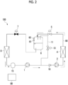
Fig. 2 is a circuit diagram showing a configuration of a refrigerating apparatus according to the first embodiment of the present disclosure, which shows a state before an operation is stopped. -
Fig. 3 is a circuit diagram showing a configuration of a refrigerating apparatus according to the first embodiment of the present disclosure, which shows a state after the operation is stopped. -
Fig. 4 is a circuit diagram showing a configuration of a refrigerating apparatus according to a second embodiment of the present disclosure, which shows a state before the operation is stopped. -
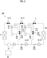
Fig. 5 is a circuit diagram showing a configuration of a refrigerating apparatus according to the second embodiment of the present disclosure, which shows a state after the operation is stopped. -
Fig. 6 is a circuit diagram showing a configuration of a refrigerating apparatus according to the second embodiment of the present disclosure, which shows a state in which a refrigerant in a receiver is transferred to another receiver during stoppage. - Hereinafter, a refrigerating
apparatus 100 according to a first embodiment of the present disclosure will be described with reference toFigs. 1 to 3 . The refrigeratingapparatus 100 is a heat pump-type apparatus that performs heat exchange between a refrigerant and air by being operated by a refrigerating cycle. - As shown in
Fig. 1 , therefrigerating apparatus 100 comprises amain circuit 90 formed as a circulation flow path, a first compressor 1 (compressor), a second compressor 2 (compressor), acondenser 4, afirst expansion valve 7, areceiver 6, a liquidlevel detection unit 61, apressure detection unit 62, asecond expansion valve 5, anevaporator 8, aninjection flow path 11, ansolenoid valve 13, anaccumulator 15, acheck valve 18, and acontrol unit 80. - The
main circuit 90 is filled with a refrigerant in a liquid or gaseous state. Thefirst compressor 1 and thesecond compressor 2 are disposed in series on themain circuit 90. That is, a discharge side of thefirst compressor 1 faces a suction side of thesecond compressor 2. As thefirst compressor 1 and thesecond compressor 2, for example, a scroll compressor, a rotary compressor, or a scrotary compressor can be used. In the following description, on themain circuit 90, a side on which thesecond compressor 2 is located when viewed from thefirst compressor 1 is referred to as a downstream side, and an opposite side thereof is referred to as an upstream side. Thecheck valve 18 is provided between thefirst compressor 1 and thesecond compressor 2. Thecheck valve 18 is configured to allow the refrigerant to circulate only in a direction from the upstream side toward the downstream side. - The
condenser 4 is disposed on the downstream side of thesecond compressor 2. Thecondenser 4 is a heat exchanger for exchanging heat between external air and the refrigerant. A fan (not shown) is provided in the vicinity of thecondenser 4, so that it is possible to forcibly perform heat exchange between the air and the refrigerant. A high-temperature high-pressure gaseous refrigerant generated by thesecond compressor 2 is condensed by passing through thecondenser 4 to become a high-temperature high-pressure liquid refrigerant. - The
second expansion valve 5 is provided on the downstream side of thecondenser 4. The high-temperature high-pressure liquid refrigerant supplied from thecondenser 4 passes through thesecond expansion valve 5, and thus the pressure and the temperature of the liquid refrigerant decrease, and the liquid refrigerant becomes a low-temperature low-pressure liquid refrigerant. - The
receiver 6 is connected to the downstream side of thesecond expansion valve 5. Thereceiver 6 is a container for storing at least a part of the liquid refrigerant that has passed through thesecond expansion valve 5. An amount of the liquid refrigerant that can be present in themain circuit 90 varies depending on an operation condition of the refrigeratingapparatus 100. Thereceiver 6 is provided to cope with this variation. The liquidlevel detection unit 61 and thepressure detection unit 62 are attached to thereceiver 6. The liquidlevel detection unit 61 detects an amount of the liquid refrigerant in thereceiver 6 and transmits the detected amount to thecontrol unit 80 as an electrical signal. Thepressure detection unit 62 detects the pressure in thereceiver 6 and transmits the detected pressure to thecontrol unit 80 as an electrical signal. - The
first expansion valve 7 is disposed further downstream of thereceiver 6. Thefirst expansion valve 7 is provided to further reduce the temperature and the pressure of the low-temperature low-pressure liquid refrigerant that has passed through thereceiver 6. Thesecond expansion valve 5 and thefirst expansion valve 7 are electromagnetic expansion valves capable of switching between open and closed states by an electrical signal from the outside. - The
evaporator 8 is provided on the downstream side of thefirst expansion valve 7. Theevaporator 8 is a heat exchanger for exchanging heat between the external air and the refrigerant. A fan (not shown) is provided in the vicinity of theevaporator 8, so that it is possible to forcibly perform heat exchange between the air and the refrigerant. The low-temperature low-pressure liquid refrigerant that has passed through thefirst expansion valve 7 evaporates by being heat-exchanged with the external air when passing through theevaporator 8, and thus becomes a low-temperature low-pressure gaseous refrigerant. - The
accumulator 15 is provided on the downstream side of theevaporator 8. Theaccumulator 15 is a container for storing the liquid refrigerant that has not been evaporated in theevaporator 8. After a liquid component is removed in theaccumulator 15, the gaseous refrigerant is sent to thefirst compressor 1 again to be compressed. The refrigeratingapparatus 100 is operated by continuously repeating such a cycle (refrigerating cycle). - The
injection flow path 11 connects thereceiver 6 and a portion between thecheck valve 18 and the first compressor 1 (that is, the low pressure-side compressor) described above. Thesolenoid valve 13 is provided on theinjection flow path 11. Thesolenoid valve 13 can switch between open and closed states thereof by an electrical signal from the outside. - The
control unit 80 is provided to switch the open and closed states of the respective valve devices described above and operation states of thefirst compressor 1 and thesecond compressor 2 by electrical signals. Specifically, thecontrol unit 80 can switch the open and closed states of thefirst expansion valve 7, thesecond expansion valve 5, and thesolenoid valve 13. In addition, thecontrol unit 80 can switch driving and stopping of thefirst compressor 1 and thesecond compressor 2. - Next, an example of an operation of the refrigerating
apparatus 100 will be described. As shown inFig. 1 , in a normal operation of the refrigeratingapparatus 100, thecontrol unit 80 closes thesolenoid valve 13. As a result, theinjection flow path 11 is closed, and the refrigerant circulates only in themain circuit 90. The refrigerant circulates in themain circuit 90, and thus the above-described refrigerating cycle continuously occurs. - Next, an operation when stopping the refrigerating
apparatus 100 will be described with reference toFigs. 2 and3 . In therefrigerating apparatus 100 as described above, heretofore, in general, in a case where an operation is stopped, the refrigerant is present uniformly on a pipe path. Therefore, it is necessary to secure pressure resistance performance of the pipe and various devices to a certain level or higher. As a result, in particular, it is necessary to make pressure resistance performance of the low pressure-sidefirst compressor 1 substantially the same as pressure resistance performance of the high pressure-sidesecond compressor 2, which causes an increase in cost. - Therefore, the refrigerating
apparatus 100 according to the present embodiment is configured to perform an operation described below to recover the refrigerant in thereceiver 6. As shown inFig. 2 , first, thecontrol unit 80 closes thefirst expansion valve 7. Thus, the downstream side of thereceiver 6 in themain circuit 90 is blocked. As a result, the refrigerant in themain circuit 90 and theinjection flow path 11 is sequentially stored in thereceiver 6. - Thereafter, as shown in
Fig. 3 , in a case where the liquidlevel detection unit 61 detects that thereceiver 6 is filled with the liquid refrigerant (the amount of the refrigerant reaches an upper limit value), thecontrol unit 80 closes thesecond expansion valve 5 and thesolenoid valve 13. Thus, thereceiver 6 is disconnected from themain circuit 90. Subsequently, thecontrol unit 80 stops the driving of thefirst compressor 1 and thesecond compressor 2. As a result, the refrigeratingapparatus 100 is stopped. - As described above, in the
refrigerating apparatus 100 according to the present embodiment, the refrigerant present in themain circuit 90 and each device can be recovered in thereceiver 6 by operating thefirst compressor 1 and thesecond compressor 2 in a state in which thefirst expansion valve 7 is closed before the operation is stopped. Therefore, in a state in which the operation of the refrigeratingapparatus 100 is stopped, the refrigerant is less likely to remain in themain circuit 90 or each device, and the pressure resistance performance of the low pressure-sidefirst compressor 1 can be particularly reduced. As a result, it is possible to reduce manufacturing costs or maintenance costs of the refrigeratingapparatus 100. - In addition, according to the above configuration, the
receiver 6 is in a state of being disconnected from the main circuit by closing thesecond expansion valve 5 in addition to thesolenoid valve 13. Thus, the refrigerant can be stably sealed in thereceiver 6. - The first embodiment of the present disclosure has been described above. Various changes or improvements can be made to the above configuration without departing from the concept of the present disclosure.
- Next, a refrigerating
apparatus 200 according to a second embodiment of the present disclosure will be described with reference toFigs. 4 to 6 . The same configurations as in the first embodiment described above are denoted by the same reference signs, and detailed descriptions thereof will not be repeated. - As shown in
Fig. 4 , in the present embodiment, the number of compressors is different from that in the first embodiment. Specifically, two high pressure-sidesecond compressors main circuit 90 in addition to a lowest pressure-sidefirst compressor 1. One check valve 18 (18a, 18b) is provided on the upstream side of each of thesecond compressors - Further, in the present embodiment, the
receiver 6, thefirst expansion valve 7, theinjection flow path 11, and thesolenoid valve 13 described in the first embodiment are provided in a plurality of sets (two sets), respectively. In the following description, thereceiver 6, thefirst expansion valve 7, theinjection flow path 11, and thesolenoid valve 13 which are located on a relatively downstream side on themain circuit 90 are referred to as adownstream receiver 6a, a downstreamfirst expansion valve 7a, a downstreaminjection flow path 11a, and adownstream solenoid valve 13a, respectively. In addition, devices that are located on a relatively upstream side are referred to as anupstream receiver 6b, an upstreamfirst expansion valve 7b, an upstreaminjection flow path 11b, and anupstream solenoid valve 13b, respectively. - The downstream
injection flow path 11a connects thedownstream receiver 6a and a portion between thefirst compressor 1 and thecheck valve 18a. The upstreaminjection flow path 11b connects theupstream receiver 6b and a portion between thesecond compressor 2a and thecheck valve 18b. - Subsequently, an operation when stopping the refrigerating
apparatus 200 will be described. As shown inFig. 4 , before the stopping, thecontrol unit 80 first closes the downstreamfirst expansion valve 7a. As a result, the refrigerant downstream of the downstreamfirst expansion valve 7a on themain circuit 90 is sequentially recovered in thedownstream receiver 6a. - Thereafter, when it is detected that the
downstream receiver 6a is filled with the refrigerant, thecontrol unit 80 closes the upstreamfirst expansion valve 7b and thedownstream solenoid valve 13a as shown inFig. 5 . As a result, thedownstream receiver 6a is disconnected from themain circuit 90. Thereafter, the refrigerant that still remains on themain circuit 90 is stored in theupstream receiver 6b. Finally, when it is detected that theupstream receiver 6b is also filled with the refrigerant, thecontrol unit 80 closes thesecond expansion valve 5 and theupstream solenoid valve 13b. Thus, theupstream receiver 6b is also disconnected from themain circuit 90. Thereafter, thecontrol unit 80 stops thefirst compressor 1 and thesecond compressors apparatus 200 is stopped. - In this way, the refrigerant is sequentially stored in a plurality of the
receivers 6 from thedownstream receiver 6 to theupstream receiver 6, so that the refrigerant in themain circuit 90 and each device is recovered. - Meanwhile, in a case where the refrigerating
apparatus 200 is stopped as described above, the pressure in thereceiver 6 may increase due to an influence of an outside air temperature. For example, a case where thepressure detection unit 62 detects that the pressure in thedownstream receiver 6a is equal to or greater than a predetermined upper limit pressure is considered. In this case, as shown inFig. 6 , thecontrol unit 80 opens only thedownstream solenoid valve 13a and thesecond expansion valve 5. In this state, thecontrol unit 80 drives thefirst compressor 1 and thesecond compressors downstream receiver 6a flows toward theupstream receiver 6b through the downstreaminjection flow path 11a and themain circuit 90. Thecontrol unit 80 continues this operation until the pressure in thedownstream receiver 6a becomes less than the upper limit pressure. - As described above, according to the above configuration, in the
refrigerating apparatus 200 including the plurality ofreceivers 6, thereceivers 6 can be sequentially filled with the refrigerant from the downstream side to the upstream side. As a result, it is possible to store a larger amount of refrigerant in the plurality ofreceivers 6. - In addition, according to the above configuration, in a case where the pressure in the
receiver 6 is increased during the stop of the refrigeratingapparatus 200, the refrigerant in thereceiver 6 located on the downstream side can be transferred to theother receiver 6 located on the upstream side by driving the compressor in a state in which theinjection flow path 11 connected to thereceiver 6 located on the downstream side is opened. Accordingly, the pressure in eachreceiver 6 can be maintained to be equal to or less than the upper limit pressure. - The embodiments of the present disclosure have been described above. Various changes or improvements can be made to the above configuration without departing from the concept of the present disclosure. For example, in each of the above-described embodiments, the refrigerating
apparatus 100 for two-stage compression including thefirst compressor 1 and thesecond compressor 2, and the refrigeratingapparatus 200 for three-stage compression including thefirst compressor 1 and thesecond compressors - The refrigerating
apparatus 100 and the refrigeratingapparatus 200 described in the embodiments are understood as follows, for example. -
- (1) A refrigerating apparatus 100 according to a first aspect includes a main circuit 90 as a circulation flow path through which a refrigerant circulates; a plurality of compressors (a first compressor 1 and a second compressor 2) that are disposed in series on the main circuit 90; a check valve 18 that is disposed between the plurality of compressors; a condenser 4 that is disposed on a downstream side of the plurality of compressors; a receiver 6 that is disposed on a downstream side of the condenser 4; a first expansion valve 7 that is disposed on a downstream side of the receiver 6; an evaporator 8 that is disposed on a downstream side of the first expansion valve 7; an injection flow path 11 that connects the receiver 6 and an upstream side of the check valve 18 between the plurality of compressors; an solenoid valve 13 that is disposed on the injection flow path 11; a liquid level detection unit 61 that detects an amount of a liquid component of the refrigerant stored in the receiver 6; and a control unit 80, in which the control unit 80 closes the first expansion valve 7 before stopping the compressor and closes the solenoid valve 13 at a point in time when the liquid level detection unit 61 detects that the amount of the liquid component in the receiver 6 has reached a predetermined upper limit value.
According to the above configuration, the refrigerant present in themain circuit 90 and each device can be recovered in thereceiver 6 by operating the compressors in a state in which thefirst expansion valve 7 is closed before stopping the operation of the refrigeratingapparatus 100. Therefore, in a state in which the operation of the refrigeratingapparatus 100 is stopped, the refrigerant is less likely to remain in themain circuit 90 or each device, and the pressure resistance performance of the low pressure-side compressor can be particularly reduced. - (2) A
refrigerating apparatus 200 according to a second aspect includes a plurality of sets of thereceivers 6, thefirst expansion valves 7, theinjection flow paths 11, and thesolenoid valves 13 that are disposed in series on themain circuit 90, in which thecontrol unit 80 performs control of closing thefirst expansion valve 7 before stopping the compressor and closing thesolenoid valve 13 at a point in time when the liquidlevel detection unit 61 detects that the amount of the liquid component in thereceiver 6 has reached the upper limit value in a sequence from thefirst expansion valve 7 and thesolenoid valve 13 that are located on a most downstream side to thefirst expansion valve 7 and thesolenoid valve 13 that are located on a most upstream side among the plurality of sets of thefirst expansion valves 7 and thesolenoid valves 13.
According to the above configuration, in therefrigerating apparatus 200 including the plurality ofreceivers 6, thereceivers 6 can be sequentially filled with the refrigerant from the downstream side to the upstream side. As a result, it is possible to store a larger amount of refrigerant in the plurality ofreceivers 6. - (3) The
refrigerating apparatus 200 according to a third aspect further includes apressure detection unit 62 that detects a pressure in thereceiver 6, in which in a case where thepressure detection unit 62 detects that the pressure in thereceiver 6 located on a relatively upstream side among the plurality ofreceivers 6 is equal to or greater than a predetermined upper limit pressure while the compressor is stopped, thecontrol unit 80 closes thesolenoid valve 13 on theinjection flow path 11 connected to thereceiver 6 located on the relatively upstream side, opens thesolenoid valve 13 on theinjection flow path 11 connected to thereceiver 6 located on a relatively downstream side, and drives the compressor.
Here, during the stop of the refrigeratingapparatus 200, the pressure in thereceiver 6 may increase due to the influence of the outside air temperature. According to the above configuration, in such a case, the refrigerant in thereceiver 6 located on the downstream side can be transferred to theother receiver 6 located on the upstream side by driving the compressor in a state in which theinjection flow path 11 connected to thereceiver 6 located on the downstream side is opened. Accordingly, the pressure in eachreceiver 6 can be maintained to be equal to or less than the upper limit pressure. - (4) The
refrigerating apparatus 100 according to a fourth aspect further includes asecond expansion valve 5 that is disposed between thecondenser 4 and thereceiver 6, in which thecontrol unit 80 closes thesolenoid valve 13 and thesecond expansion valve 5 at a point in time when the liquidlevel detection unit 61 detects that an amount of the refrigerant in thereceiver 6 has reached a predetermined upper limit value. - According to the above configuration, the
receiver 6 is in a state of being disconnected from the main circuit by closing thesecond expansion valve 5 in addition to thesolenoid valve 13. Thus, the refrigerant can be stably sealed in thereceiver 6. - According to the present disclosure, it is possible to provide a refrigerating apparatus that can be manufactured at a lower cost.
-
- 100, 200: refrigerating apparatus
- 90: main circuit
- 80: control unit
- 1: first compressor
- 2, 2a, 2b: second compressor
- 4: condenser
- 5: second expansion valve
- 6: receiver
- 6a: downstream receiver
- 6b: upstream receiver
- 7: first expansion valve
- 7a: downstream first expansion valve
- 7b: upstream first expansion valve
- 8: evaporator
- 11: injection flow path
- 11a: downstream injection flow path
- 11b: upstream injection flow path
- 13: solenoid valve
- 13a: downstream solenoid valve
- 13b: upstream solenoid valve
- 15: accumulator
- 18, 18a, 18b: check valve
Claims (4)
- A refrigerating apparatus comprising:a main circuit as a circulation flow path through which a refrigerant circulates;a plurality of compressors that are disposed in series on the main circuit;a check valve that is disposed between the plurality of compressors;a condenser that is disposed on a downstream side of the plurality of compressors;a receiver that is disposed on a downstream side of the condenser;a first expansion valve that is disposed on a downstream side of the receiver;an evaporator that is disposed on a downstream side of the first expansion valve;an injection flow path that connects the receiver and an upstream side of the check valve between the plurality of compressors;an solenoid valve that is disposed on the injection flow path;a liquid level detection unit that detects an amount of a liquid component of the refrigerant stored in the receiver; anda control unit,wherein the control unit closes the first expansion valve before stopping the compressor and closes the solenoid valve at a point in time when the liquid level detection unit detects that the amount of the liquid component in the receiver has reached a predetermined upper limit value.
- The refrigerating apparatus according to Claim 1,wherein a plurality of sets of the receivers, the first expansion valves, the injection flow paths, and the solenoid valves that are disposed in series on the main circuit are provided, andthe control unit performs control of closing the first expansion valve before stopping the compressor and closing the solenoid valve at a point in time when the liquid level detection unit detects that the amount of the liquid component in the receiver has reached the upper limit value in a sequence from the first expansion valve and the solenoid valve that are located on a most downstream side to the first expansion valve and the solenoid valve that are located on a most upstream side among the plurality of sets of the first expansion valves and the solenoid valves.
- The refrigerating apparatus according to Claim 2, further comprising a pressure detection unit that detects a pressure in the receiver,
wherein in a case where the pressure detection unit detects that the pressure in the receiver located on a relatively upstream side among the plurality of receivers is equal to or greater than a predetermined upper limit pressure while the compressor is stopped, the control unit closes the solenoid valve on the injection flow path connected to the receiver located on the relatively upstream side, opens the solenoid valve on the injection flow path connected to the receiver located on a relatively downstream side, and drives the compressor. - The refrigerating apparatus according to any one of Claims 1 to 3, further comprising a second expansion valve that is disposed between the condenser and the receiver,
wherein the control unit closes the solenoid valve and the second expansion valve at a point in time when the liquid level detection unit detects that an amount of the refrigerant in the receiver has reached a predetermined upper limit value.
Applications Claiming Priority (2)
| Application Number | Priority Date | Filing Date | Title |
|---|---|---|---|
| JP2021170169A JP7814138B2 (en) | 2021-10-18 | 2021-10-18 | Refrigeration equipment |
| PCT/JP2022/038399 WO2023068197A1 (en) | 2021-10-18 | 2022-10-14 | Freezing apparatus |
Publications (2)
| Publication Number | Publication Date |
|---|---|
| EP4411278A1 true EP4411278A1 (en) | 2024-08-07 |
| EP4411278A4 EP4411278A4 (en) | 2025-01-15 |
Family
ID=86059276
Family Applications (1)
| Application Number | Title | Priority Date | Filing Date |
|---|---|---|---|
| EP22883501.3A Pending EP4411278A4 (en) | 2021-10-18 | 2022-10-14 | FREEZING DEVICE |
Country Status (3)
| Country | Link |
|---|---|
| EP (1) | EP4411278A4 (en) |
| JP (1) | JP7814138B2 (en) |
| WO (1) | WO2023068197A1 (en) |
Families Citing this family (1)
| Publication number | Priority date | Publication date | Assignee | Title |
|---|---|---|---|---|
| CN118816418B (en) * | 2024-09-18 | 2024-12-06 | 宁波惠康智能科技有限公司 | High-efficient low temperature evaporation plant |
Family Cites Families (9)
| Publication number | Priority date | Publication date | Assignee | Title |
|---|---|---|---|---|
| JP2001133056A (en) | 1999-11-04 | 2001-05-18 | Mitsubishi Electric Corp | Air conditioner |
| JP2013139938A (en) | 2011-12-28 | 2013-07-18 | Daikin Industries Ltd | Refrigeration device |
| WO2014031559A1 (en) * | 2012-08-24 | 2014-02-27 | Carrier Corporation | Transcritical refrigerant vapor compression system high side pressure control |
| JP2018009767A (en) | 2016-07-15 | 2018-01-18 | ダイキン工業株式会社 | Refrigeration equipment |
| EP3598037B1 (en) | 2017-03-13 | 2024-02-21 | Mitsubishi Electric Corporation | Refrigeration cycle device |
| JP2020204454A (en) | 2019-06-17 | 2020-12-24 | パナソニック株式会社 | Refrigeration cycle device |
| DK4030116T3 (en) * | 2019-09-09 | 2023-11-13 | Mitsubishi Electric Corp | OUTDOOR UNIT AND REFRIGERATION CIRCUIT |
| JP7527126B2 (en) | 2020-04-14 | 2024-08-02 | 古河電気工業株式会社 | Processing device, processing method, processing program, and information processing system |
| CN113503653B (en) | 2021-08-04 | 2022-05-06 | 珠海格力电器股份有限公司 | Multi-compressor refrigeration system and air conditioner |
-
2021
- 2021-10-18 JP JP2021170169A patent/JP7814138B2/en active Active
-
2022
- 2022-10-14 WO PCT/JP2022/038399 patent/WO2023068197A1/en not_active Ceased
- 2022-10-14 EP EP22883501.3A patent/EP4411278A4/en active Pending
Also Published As
| Publication number | Publication date |
|---|---|
| WO2023068197A1 (en) | 2023-04-27 |
| EP4411278A4 (en) | 2025-01-15 |
| JP2023060524A (en) | 2023-04-28 |
| JP7814138B2 (en) | 2026-02-16 |
Similar Documents
| Publication | Publication Date | Title |
|---|---|---|
| EP2551612B1 (en) | Supercritical-cycle heat pump | |
| EP2309204B1 (en) | Refrigeration device | |
| EP3279580B1 (en) | Air-conditioning device | |
| US9651288B2 (en) | Refrigeration apparatus and refrigeration cycle apparatus | |
| CN109099610B (en) | Refrigeration system, air conditioner and air conditioner control method for supplementing air and increasing enthalpy | |
| EP2863151B1 (en) | Two-stage compression cycle | |
| AU2008330740B2 (en) | Refrigeration apparatus | |
| EP1795833A1 (en) | Refrigerating apparatus | |
| US20110005269A1 (en) | Refrigeration apparatus | |
| KR100564444B1 (en) | Apparatus and method for preventing accumulation of liquid refrigerant in air conditioners | |
| JP5783783B2 (en) | Heat source side unit and refrigeration cycle apparatus | |
| JP2013024538A (en) | Refrigeration unit | |
| CN105593615A (en) | Refrigeration device | |
| WO2023068197A1 (en) | Freezing apparatus | |
| CN110411082B (en) | Refrigerant recovery system, control method and device thereof, controller and air conditioning system | |
| CN112361634A (en) | Two-stage compression refrigeration system, refrigeration control method and refrigeration equipment | |
| AU2023242028A1 (en) | Air conditioner | |
| EP4145061B1 (en) | Refrigerating apparatus | |
| EP4350256A1 (en) | Multi-stage compression refrigeration device | |
| EP2565562B1 (en) | Refrigerant circuit system | |
| US20050150246A1 (en) | Refrigerating equipment | |
| EP2525168B1 (en) | Supercritical steam compression heat pump and hot-water supply unit | |
| EP4421410A1 (en) | Binary refrigeration device | |
| JPH04313647A (en) | Heat pump type air conditioner | |
| CN113847761B (en) | Method for filling refrigerant in air conditioning system |
Legal Events
| Date | Code | Title | Description |
|---|---|---|---|
| STAA | Information on the status of an ep patent application or granted ep patent |
Free format text: STATUS: THE INTERNATIONAL PUBLICATION HAS BEEN MADE |
|
| PUAI | Public reference made under article 153(3) epc to a published international application that has entered the european phase |
Free format text: ORIGINAL CODE: 0009012 |
|
| STAA | Information on the status of an ep patent application or granted ep patent |
Free format text: STATUS: REQUEST FOR EXAMINATION WAS MADE |
|
| 17P | Request for examination filed |
Effective date: 20240430 |
|
| AK | Designated contracting states |
Kind code of ref document: A1 Designated state(s): AL AT BE BG CH CY CZ DE DK EE ES FI FR GB GR HR HU IE IS IT LI LT LU LV MC ME MK MT NL NO PL PT RO RS SE SI SK SM TR |
|
| A4 | Supplementary search report drawn up and despatched |
Effective date: 20241218 |
|
| RIC1 | Information provided on ipc code assigned before grant |
Ipc: F25B 43/00 20060101ALI20241212BHEP Ipc: F25B 1/10 20060101ALI20241212BHEP Ipc: F25B 1/00 20060101AFI20241212BHEP |
|
| DAV | Request for validation of the european patent (deleted) | ||
| DAX | Request for extension of the european patent (deleted) |