EP4411243A1 - Injector with fairing and annular passage for hydrogen-driven gas turbine engine - Google Patents
Injector with fairing and annular passage for hydrogen-driven gas turbine engine Download PDFInfo
- Publication number
- EP4411243A1 EP4411243A1 EP24155603.4A EP24155603A EP4411243A1 EP 4411243 A1 EP4411243 A1 EP 4411243A1 EP 24155603 A EP24155603 A EP 24155603A EP 4411243 A1 EP4411243 A1 EP 4411243A1
- Authority
- EP
- European Patent Office
- Prior art keywords
- convergent
- section
- fairing
- divergent
- injector
- Prior art date
- Legal status (The legal status is an assumption and is not a legal conclusion. Google has not performed a legal analysis and makes no representation as to the accuracy of the status listed.)
- Pending
Links
Images

Classifications
-
- F—MECHANICAL ENGINEERING; LIGHTING; HEATING; WEAPONS; BLASTING
- F23—COMBUSTION APPARATUS; COMBUSTION PROCESSES
- F23R—GENERATING COMBUSTION PRODUCTS OF HIGH PRESSURE OR HIGH VELOCITY, e.g. GAS-TURBINE COMBUSTION CHAMBERS
- F23R3/00—Continuous combustion chambers using liquid or gaseous fuel
- F23R3/28—Continuous combustion chambers using liquid or gaseous fuel characterised by the fuel supply
-
- F—MECHANICAL ENGINEERING; LIGHTING; HEATING; WEAPONS; BLASTING
- F23—COMBUSTION APPARATUS; COMBUSTION PROCESSES
- F23R—GENERATING COMBUSTION PRODUCTS OF HIGH PRESSURE OR HIGH VELOCITY, e.g. GAS-TURBINE COMBUSTION CHAMBERS
- F23R3/00—Continuous combustion chambers using liquid or gaseous fuel
- F23R3/02—Continuous combustion chambers using liquid or gaseous fuel characterised by the air-flow or gas-flow configuration
- F23R3/16—Continuous combustion chambers using liquid or gaseous fuel characterised by the air-flow or gas-flow configuration with devices inside the flame tube or the combustion chamber to influence the air or gas flow
-
- F—MECHANICAL ENGINEERING; LIGHTING; HEATING; WEAPONS; BLASTING
- F23—COMBUSTION APPARATUS; COMBUSTION PROCESSES
- F23R—GENERATING COMBUSTION PRODUCTS OF HIGH PRESSURE OR HIGH VELOCITY, e.g. GAS-TURBINE COMBUSTION CHAMBERS
- F23R3/00—Continuous combustion chambers using liquid or gaseous fuel
- F23R3/28—Continuous combustion chambers using liquid or gaseous fuel characterised by the fuel supply
- F23R3/286—Continuous combustion chambers using liquid or gaseous fuel characterised by the fuel supply having fuel-air premixing devices
-
- F—MECHANICAL ENGINEERING; LIGHTING; HEATING; WEAPONS; BLASTING
- F23—COMBUSTION APPARATUS; COMBUSTION PROCESSES
- F23R—GENERATING COMBUSTION PRODUCTS OF HIGH PRESSURE OR HIGH VELOCITY, e.g. GAS-TURBINE COMBUSTION CHAMBERS
- F23R2900/00—Special features of, or arrangements for continuous combustion chambers; Combustion processes therefor
- F23R2900/00002—Gas turbine combustors adapted for fuels having low heating value [LHV]
Definitions
- a gas turbine engine typically includes a fan section, a compressor section, a combustor section and a turbine section. Air entering the compressor section is compressed and delivered into the combustion section where it is mixed with fuel and ignited to generate a high-pressure and temperature exhaust gas flow. The high-pressure and temperature exhaust gas flow expands through the turbine section to drive the compressor and the fan section.
- the compressor section may include low and high pressure compressors, and the turbine section may also include low and high pressure turbines.
- LHF liquid hydrocarbon fuels
- the fuel supply system and liquid injectors are designed for handling and efficient burning of the LHF. For instance, as liquid is much denser than the air (gas) it is to be mixed with, it is necessary for the liquid injectors to atomize the LHF into tiny droplets in order to facilitate more uniform burning. More recently it has been proposed to utilize hydrogen (H 2 ) as a fuel.
- H 2 hydrogen
- An injector includes a convergent-divergent nozzle head, a fairing, a fuel nozzle, and an air nozzle.
- the convergent-divergent nozzle head has in fluid communication in series a convergent section, a throat, and a divergent section.
- the fairing extends through the convergent section and through the throat to define an annular passage between the fairing and the convergent-divergent nozzle head that has an outlet in the divergent section.
- the fuel nozzle has an annular fuel feed conduit that opens to the annular passage for providing hydrogen fuel.
- the gas nozzle is upstream of the convergent-divergent nozzle head for providing gas into the annular passage.
- a gas turbine engine includes a combustor section that has a combustion chamber, a hydrogen source, and an injector as in any of the foregoing embodiments, for introducing hydrogen from the hydrogen source and gas into the combustion chamber.
- the present disclosure may include any one or more of the individual features disclosed above and/or below alone or in any combination thereof.
- like reference numerals designate like elements where appropriate and reference numerals with the addition of one-hundred or multiples thereof designate modified elements that are understood to incorporate the same features and benefits of the corresponding elements.
- FIG. 1 schematically illustrates a gas turbine engine 20.
- the example gas turbine engine 20 is a turbofan that generally incorporates a fan section 22, a compressor section 24, a combustor section 26, and a turbine section 28.
- the fan section 22 drives air along a bypass flow path B in a bypass duct defined within a nacelle 30.
- the turbine engine 20 intakes air along a core flow path C into the compressor section 24 for compression and communication into the combustor section 26.
- the compressed air or other combustion gas is mixed with fuel from a fuel system 32 and ignited by igniter 34 to generate an exhaust gas flow that expands through the turbine section 28 and is exhausted through exhaust nozzle 36.
- turbofan turbine engine in the disclosed non-limiting embodiment, it should be understood that the concepts described herein are not limited to use with turbofans as the teachings may be applied to other types of turbine engines.
- the propulsor may be an enclosed fan, the propulsor may be an open propeller.
- the engine 20 of the present disclosure is designed to use gaseous fuel, such as hydrogen, in the fuel system 32.
- the fuel system 32 may carry liquid cryogenic hydrogen or gaseous hydrogen, both of which are provided to the combustor section 26 as gaseous hydrogen.
- a challenge to using hydrogen is that because it is a gas, its handling and combustion properties differ from that of LHF. For instance, hydrogen does not require atomization like a liquid, and hydrogen has higher flammability and different flame characteristics than LHF. Accordingly, injector nozzles that are designed for hydrogen are needed.
- the engine 20 includes one or more injectors 38 for introducing the hydrogen fuel into the combustor section 26.
- the injector 38 is arranged on a combustion chamber 26a of the combustor section 26 for introducing hydrogen and gas (e.g., air in the examples herein).
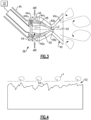
- Figure 3 illustrates an isolated view of an example of the injector 38.
- the injector 38 includes a convergent-divergent nozzle head 40, a fairing 42, a fuel nozzle 44, and a gas nozzle 46.
- the convergent-divergent nozzle head 40 defines a central nozzle axis A2 and has in fluid communication in series a convergent section 40a, a throat 40b, and a divergent section 40c.
- the fairing 42 extends along the nozzle axis A2, through the convergent section 40a and through the throat 40b to define an annular passage 48 between the fairing 42 and the convergent-divergent nozzle head 40.
- the annular passage 48 has an outlet 48a in the divergent section 40c.
- the fuel nozzle 44 is connected with the fuel system 32 (hydrogen source) via feed conduit 45.
- the fuel nozzle 44 has an annular fuel feed conduit 44a that opens at a forward face 44b of the fuel nozzle 44 to the annular passage 48 for providing hydrogen fuel from the fuel system 32.
- the gas nozzle 46 is upstream of the convergent-divergent nozzle head 40 for providing air or other combustion gas into the annular passage 48, such as air from the compressor section 24.
- the hydrogen and air are mixed in the convergent-divergent nozzle head 40 and then injected into the combustor chamber 26a for ignition.
- a "conduit" as used herein is defined by one or more structures that together convey a fluid from one point to another.
- a conduit conveying fluid from point A to point B may include one of, or a combination of: a tube, an aperture defined through a part of an engine, a filter, a pump, and so on, depending on the application and context as would be understood by a person of ordinary skill in the art reading the present disclosure.
- the fairing 42 extends off of the forward face 44b of the fuel nozzle 44.
- the fairing 42 diametrically increases in size along the nozzle axis A2 from the forward face 44b to a first axial location L1 in the convergent section 40a.
- the fairing 42 thus provides a relatively large region for the hydrogen and air to initially diffuse and mix near the forward face 44b of the fuel nozzle 44.
- the feed conduit 44a distributes hydrogen through multiple distribution conduits 44c to locations axially beyond the axial location L1.
- the diametric increase in the size of the fairing 42 up to the first axial location L1 serves to taper the annular passage 48 in the convergent section 40a, to facilitate the turning of the radial swirling air flow and the multiple distribution conduits 44c.
- the fairing 42 then diametrically decreases in size from the first axial location L1 to a second axial location L2 in the divergent section 40c.
- the angle of convergence of the convergent section 40a is steeper than the diametric decrease such that the annular passage 48 continues to taper through the throat 40b to accelerate the hydrogen and air into the divergent section 40c.
- the convergent-divergent nozzle head 40 includes an open-cell metallic foam 50 disposed in the annular passage 48.
- the foam 50 is disposed in the annular passage 48 between the first axial location L1 and the second axial location L2, upstream of the throat 40b.
- the cells of the foam 50 create a tortuous path for flow of the hydrogen and air to thereby promote mixing.
- the open-cell metallic foam 50 is formed of an alloy that has low susceptibility to hydrogen embrittlement, such as but not limited to, stainless steel or nickel alloy, and which is corrosion resistant and temperature resistant at the expected operating conditions.
- the foam 50 also serves as a flame arrestor, allowing feed flow of hydrogen and air but facilitating the prevention of flame propagation back through the throat 40b.
- select surfaces of convergent-divergent nozzle head 40 and the fairing 42 that are in contact with hydrogen or air are surface-treated to further enhance mixing.
- Figure 4 shows an example surface 52, which may be a surface of the convergent-divergent nozzle head 40 and/or the fairing 42.
- the surface 52 has been treated to have a surface roughness 54 of 100-300Ra.
- the surface roughness 54 induces turbulent flow F, contributing to mixing of the hydrogen and air.
- An injector 38 includes a convergent-divergent nozzle head 40 that defines a nozzle axis A2 that has, in fluid communication in series, a convergent section 40a, a throat 40b, and a divergent section 40c.
- a fairing 42 extends along the nozzle axis A2 through the convergent section 40a, and through the throat 40b to define an annular passage 48 between the fairing 42 and the convergent-divergent nozzle head 40.
- the annular passage 48 has an outlet 48a in the divergent section 40c.
- a fuel nozzle 44 has an annular fuel feed conduit 44a along the nozzle axis A2 and opens to the annular passage 48 for providing hydrogen fuel.
- the convergent-divergent nozzle head 40 includes an open-cell metallic foam 50 disposed in the annular passage 48.
- the annular passage 48 tapers through the convergent section 40a.
- the fuel nozzle 44 includes a forward face 44b that faces the convergent-divergent nozzle head 40, and the fairing 42 extends off of the forward face 44b.
- the fairing 42 diametrically increases in size along the nozzle axis A2 from the forward face 44b to a first axial location L1 in the convergent section 40a.
- the fairing 42 diametrically decreases in size from the first axial location L1 to a second axial location L2 in the divergent section 40c.
- the convergent-divergent nozzle head 40 includes an open-cell metallic foam 50 disposed in the annular passage 48 between the first axial location L1 and the second axial location L2.
- the convergent-divergent nozzle head 40 includes a nozzle surface 52 and fairing 42 includes a fairing surface 52, and the nozzle surface and the fairing surface 52 have a surface roughness 54 of 100-300Ra.
- a gas turbine engine 20 includes a combustor section 26 that has a combustion chamber 26a, a hydrogen source 32, and an injector 38 as in any of the foregoing examples.
Landscapes
- Engineering & Computer Science (AREA)
- Chemical & Material Sciences (AREA)
- Combustion & Propulsion (AREA)
- Mechanical Engineering (AREA)
- General Engineering & Computer Science (AREA)
- Pre-Mixing And Non-Premixing Gas Burner (AREA)
- Nozzles (AREA)
Abstract
Description
- A gas turbine engine typically includes a fan section, a compressor section, a combustor section and a turbine section. Air entering the compressor section is compressed and delivered into the combustion section where it is mixed with fuel and ignited to generate a high-pressure and temperature exhaust gas flow. The high-pressure and temperature exhaust gas flow expands through the turbine section to drive the compressor and the fan section. The compressor section may include low and high pressure compressors, and the turbine section may also include low and high pressure turbines.
- Present gas turbine engines use liquid hydrocarbon fuels (LHF). LHF is provided through a fuel supply system and introduced into the combustor by liquid injectors. The fuel supply system and liquid injectors are designed for handling and efficient burning of the LHF. For instance, as liquid is much denser than the air (gas) it is to be mixed with, it is necessary for the liquid injectors to atomize the LHF into tiny droplets in order to facilitate more uniform burning. More recently it has been proposed to utilize hydrogen (H2) as a fuel.
- An injector according to an example of the present disclosure includes a convergent-divergent nozzle head, a fairing, a fuel nozzle, and an air nozzle. The convergent-divergent nozzle head has in fluid communication in series a convergent section, a throat, and a divergent section. The fairing extends through the convergent section and through the throat to define an annular passage between the fairing and the convergent-divergent nozzle head that has an outlet in the divergent section. The fuel nozzle has an annular fuel feed conduit that opens to the annular passage for providing hydrogen fuel. The gas nozzle is upstream of the convergent-divergent nozzle head for providing gas into the annular passage.
- A gas turbine engine according to an example of the present disclosure includes a combustor section that has a combustion chamber, a hydrogen source, and an injector as in any of the foregoing embodiments, for introducing hydrogen from the hydrogen source and gas into the combustion chamber.
- The present disclosure may include any one or more of the individual features disclosed above and/or below alone or in any combination thereof.
- The various features and advantages of the present disclosure will become apparent to those skilled in the art from the following detailed description. The drawings that accompany the detailed description can be briefly described as follows.
-
Figure 1 illustrates a gas turbine engine. -
Figure 2 illustrates an injector and combustor chamber of the engine. -
Figure 3 illustrates an isolated view of an example injector. -
Figure 4 illustrates a surface-treated surface to facilitate mixing. - In this disclosure, like reference numerals designate like elements where appropriate and reference numerals with the addition of one-hundred or multiples thereof designate modified elements that are understood to incorporate the same features and benefits of the corresponding elements.
-
Figure 1 schematically illustrates agas turbine engine 20. The examplegas turbine engine 20 is a turbofan that generally incorporates afan section 22, acompressor section 24, acombustor section 26, and aturbine section 28. Thefan section 22 drives air along a bypass flow path B in a bypass duct defined within anacelle 30. Theturbine engine 20 intakes air along a core flow path C into thecompressor section 24 for compression and communication into thecombustor section 26. In thecombustor section 26, the compressed air or other combustion gas is mixed with fuel from afuel system 32 and ignited byigniter 34 to generate an exhaust gas flow that expands through theturbine section 28 and is exhausted throughexhaust nozzle 36. Although depicted as a turbofan turbine engine in the disclosed non-limiting embodiment, it should be understood that the concepts described herein are not limited to use with turbofans as the teachings may be applied to other types of turbine engines. As one example, rather than having the propulsor be an enclosed fan, the propulsor may be an open propeller. - While present gas turbine engines use liquid hydrocarbon fuels (LHF), the
engine 20 of the present disclosure is designed to use gaseous fuel, such as hydrogen, in thefuel system 32. In this regard, thefuel system 32 may carry liquid cryogenic hydrogen or gaseous hydrogen, both of which are provided to thecombustor section 26 as gaseous hydrogen. A challenge to using hydrogen is that because it is a gas, its handling and combustion properties differ from that of LHF. For instance, hydrogen does not require atomization like a liquid, and hydrogen has higher flammability and different flame characteristics than LHF. Accordingly, injector nozzles that are designed for hydrogen are needed. In these regards, theengine 20 includes one ormore injectors 38 for introducing the hydrogen fuel into thecombustor section 26. - As shown in
Figure 2 , theinjector 38 is arranged on acombustion chamber 26a of thecombustor section 26 for introducing hydrogen and gas (e.g., air in the examples herein).Figure 3 illustrates an isolated view of an example of theinjector 38. Theinjector 38 includes a convergent-divergent nozzle head 40, afairing 42, afuel nozzle 44, and agas nozzle 46. The convergent-divergent nozzle head 40 defines a central nozzle axis A2 and has in fluid communication in series aconvergent section 40a, athroat 40b, and adivergent section 40c. Thefairing 42 extends along the nozzle axis A2, through theconvergent section 40a and through thethroat 40b to define anannular passage 48 between thefairing 42 and the convergent-divergent nozzle head 40. Theannular passage 48 has anoutlet 48a in thedivergent section 40c. - The
fuel nozzle 44 is connected with the fuel system 32 (hydrogen source) viafeed conduit 45. Thefuel nozzle 44 has an annularfuel feed conduit 44a that opens at aforward face 44b of thefuel nozzle 44 to theannular passage 48 for providing hydrogen fuel from thefuel system 32. Thegas nozzle 46 is upstream of the convergent-divergent nozzle head 40 for providing air or other combustion gas into theannular passage 48, such as air from thecompressor section 24. The hydrogen and air are mixed in the convergent-divergent nozzle head 40 and then injected into thecombustor chamber 26a for ignition. A "conduit" as used herein is defined by one or more structures that together convey a fluid from one point to another. For example, a conduit conveying fluid from point A to point B may include one of, or a combination of: a tube, an aperture defined through a part of an engine, a filter, a pump, and so on, depending on the application and context as would be understood by a person of ordinary skill in the art reading the present disclosure. - In the example shown, the
fairing 42 extends off of theforward face 44b of thefuel nozzle 44. Thefairing 42 diametrically increases in size along the nozzle axis A2 from theforward face 44b to a first axial location L1 in theconvergent section 40a. Thefairing 42 thus provides a relatively large region for the hydrogen and air to initially diffuse and mix near theforward face 44b of thefuel nozzle 44. Thefeed conduit 44a distributes hydrogen throughmultiple distribution conduits 44c to locations axially beyond the axial location L1. Coupled with the convergence of theconvergent section 40a, the diametric increase in the size of thefairing 42 up to the first axial location L1 serves to taper theannular passage 48 in theconvergent section 40a, to facilitate the turning of the radial swirling air flow and themultiple distribution conduits 44c. Thefairing 42 then diametrically decreases in size from the first axial location L1 to a second axial location L2 in thedivergent section 40c. The angle of convergence of theconvergent section 40a, however, is steeper than the diametric decrease such that theannular passage 48 continues to taper through thethroat 40b to accelerate the hydrogen and air into thedivergent section 40c. - To further facilitate uniform mixing of the hydrogen and air, the convergent-
divergent nozzle head 40 includes an open-cellmetallic foam 50 disposed in theannular passage 48. In this example, thefoam 50 is disposed in theannular passage 48 between the first axial location L1 and the second axial location L2, upstream of thethroat 40b. The cells of thefoam 50 create a tortuous path for flow of the hydrogen and air to thereby promote mixing. For instance, the open-cellmetallic foam 50 is formed of an alloy that has low susceptibility to hydrogen embrittlement, such as but not limited to, stainless steel or nickel alloy, and which is corrosion resistant and temperature resistant at the expected operating conditions. Thefoam 50 also serves as a flame arrestor, allowing feed flow of hydrogen and air but facilitating the prevention of flame propagation back through thethroat 40b. - In further examples, select surfaces of convergent-
divergent nozzle head 40 and thefairing 42 that are in contact with hydrogen or air are surface-treated to further enhance mixing.Figure 4 shows anexample surface 52, which may be a surface of the convergent-divergent nozzle head 40 and/or thefairing 42. Thesurface 52 has been treated to have asurface roughness 54 of 100-300Ra. Thesurface roughness 54 induces turbulent flow F, contributing to mixing of the hydrogen and air. - This disclosure may be further understood in view of the following examples. An
injector 38 includes a convergent-divergent nozzle head 40 that defines a nozzle axis A2 that has, in fluid communication in series, aconvergent section 40a, athroat 40b, and adivergent section 40c. A fairing 42 extends along the nozzle axis A2 through theconvergent section 40a, and through thethroat 40b to define anannular passage 48 between the fairing 42 and the convergent-divergent nozzle head 40. Theannular passage 48 has anoutlet 48a in thedivergent section 40c. Afuel nozzle 44 has an annularfuel feed conduit 44a along the nozzle axis A2 and opens to theannular passage 48 for providing hydrogen fuel. There is agas nozzle 46 upstream of the convergent-divergent nozzle head 40 for providing gas into theannular passage 48. - In a further example of the foregoing example, the convergent-
divergent nozzle head 40 includes an open-cellmetallic foam 50 disposed in theannular passage 48. - In a further example of any of the foregoing examples, the
annular passage 48 tapers through theconvergent section 40a. - In a further example of any of the foregoing examples, the
fuel nozzle 44 includes aforward face 44b that faces the convergent-divergent nozzle head 40, and the fairing 42 extends off of theforward face 44b. - In a further example of any of the foregoing examples, the fairing 42 diametrically increases in size along the nozzle axis A2 from the
forward face 44b to a first axial location L1 in theconvergent section 40a. - In a further example of any of the foregoing examples, the fairing 42 diametrically decreases in size from the first axial location L1 to a second axial location L2 in the
divergent section 40c. - In a further example of any of the foregoing examples, the convergent-
divergent nozzle head 40 includes an open-cellmetallic foam 50 disposed in theannular passage 48 between the first axial location L1 and the second axial location L2. - In a further example of any of the foregoing examples, the convergent-
divergent nozzle head 40 includes anozzle surface 52 and fairing 42 includes afairing surface 52, and the nozzle surface and thefairing surface 52 have asurface roughness 54 of 100-300Ra. - A
gas turbine engine 20 according to an example of the present disclosure includes acombustor section 26 that has acombustion chamber 26a, ahydrogen source 32, and aninjector 38 as in any of the foregoing examples. - Although a combination of features is shown in the illustrated examples, not all of them need to be combined to realize the benefits of various embodiments of this disclosure. In other words, a system designed according to an embodiment of this disclosure will not necessarily include all of the features shown in any one of the Figures or all of the portions schematically shown in the Figures. Moreover, selected features of one example embodiment may be combined with selected features of other example embodiments.
- The preceding description is exemplary rather than limiting in nature. Variations and modifications to the disclosed examples may become apparent to those skilled in the art that do not necessarily depart from this disclosure. The scope of legal protection given to this disclosure can only be determined by studying the following claims.
Claims (10)
- An injector (38) for a gas turbine engine (20) comprising:a convergent-divergent nozzle head (40) defining a nozzle axis (A2) and having in fluid communication in series a convergent section (40a), a throat (40b), and a divergent section (40c);a fairing (42) extending along the nozzle axis (A2), through the convergent section (40a), and through the throat (40b) to define an annular passage (48) between the fairing (42) and the convergent-divergent nozzle head (40), the annular passage (48) having an outlet (48a) in the divergent section (40c);a fuel nozzle (44) having multiple feed conduits (44a) opening to the annular passage (48) for providing hydrogen fuel; anda gas nozzle (46) upstream of the convergent-divergent nozzle head (40) for providing gas into the annular passage (48).
- The injector (3 8) as recited in claim 1, wherein the convergent-divergent nozzle head (40) includes an open-cell metallic foam (50) disposed in the annular passage (48).
- The injector (38) as recited in claim 1 or 2, wherein the annular passage (48) tapers through the convergent section (40a).
- The injector (38) as recited in claim 1, 2 or 3, wherein the fuel nozzle (44) includes a forward face (44b) facing the convergent-divergent nozzle head (40), and the fairing (42) extends off of the forward face (44b).
- The injector (38) as recited in claim 4, wherein the fairing (42) diametrically increases in size along the nozzle axis (A2) from the forward face (44b) to a first axial location (L1) in the convergent section (40a).
- The injector (38) as recited in claim 5, wherein the fairing (42) diametrically decreases in size from the first axial location (L1) to a second axial location (L2) in the divergent section (40c).
- The injector (3 8) as recited in claim 6, wherein the convergent-divergent nozzle head (40) includes an open-cell metallic foam (50) disposed in the annular passage (48) between the first axial location (L1) and the second axial location (L2).
- The injector (38) as recited in any preceding claim, wherein the convergent-divergent nozzle head (40) includes a nozzle surface (52) and fairing (42) includes a fairing surface (52), and the nozzle surface (52) and the fairing surface (52) have a surface roughness (54) of 100-300Ra.
- A gas turbine engine (20) comprising:a combustor section (26) having a combustion chamber (26a);hydrogen source (32); andthe injector (38) of any preceding claim for introducing hydrogen from the hydrogen source (32) and air into the combustion chamber (26a).
- The gas turbine engine (20) as recited in claim 9, including a compressor section (24) providing gas to the combustor section (26), a turbine section (28) in fluid communication with the combustor section (26), and a fan coupled to be driven by the turbine section (28).
Applications Claiming Priority (1)
| Application Number | Priority Date | Filing Date | Title |
|---|---|---|---|
| US202363482819P | 2023-02-02 | 2023-02-02 |
Publications (1)
| Publication Number | Publication Date |
|---|---|
| EP4411243A1 true EP4411243A1 (en) | 2024-08-07 |
Family
ID=89843742
Family Applications (1)
| Application Number | Title | Priority Date | Filing Date |
|---|---|---|---|
| EP24155603.4A Pending EP4411243A1 (en) | 2023-02-02 | 2024-02-02 | Injector with fairing and annular passage for hydrogen-driven gas turbine engine |
Country Status (3)
| Country | Link |
|---|---|
| US (1) | US12546475B2 (en) |
| EP (1) | EP4411243A1 (en) |
| CA (1) | CA3227569A1 (en) |
Families Citing this family (1)
| Publication number | Priority date | Publication date | Assignee | Title |
|---|---|---|---|---|
| CA3281692A1 (en) * | 2024-10-28 | 2026-05-13 | Pratt & Whitney Canada Corp. | Hydrogen nozzle with multiple flow circuits and flow directing swirler |
Citations (8)
| Publication number | Priority date | Publication date | Assignee | Title |
|---|---|---|---|---|
| US3600891A (en) * | 1969-12-18 | 1971-08-24 | United Aircraft Corp | Variable area nozzle |
| US5813232A (en) * | 1995-06-05 | 1998-09-29 | Allison Engine Company, Inc. | Dry low emission combustor for gas turbine engines |
| US20080104961A1 (en) * | 2006-11-08 | 2008-05-08 | Ronald Scott Bunker | Method and apparatus for enhanced mixing in premixing devices |
| US20080163627A1 (en) * | 2007-01-10 | 2008-07-10 | Ahmed Mostafa Elkady | Fuel-flexible triple-counter-rotating swirler and method of use |
| US20090249789A1 (en) * | 2008-04-08 | 2009-10-08 | Baifang Zuo | Burner tube premixer and method for mixing air and gas in a gas turbine engine |
| US20170211807A1 (en) * | 2014-04-07 | 2017-07-27 | Siemens Aktiengesellschaft | A burner tip and a burner for a gas turbine |
| WO2017175958A1 (en) * | 2016-04-08 | 2017-10-12 | 한화테크윈주식회사 | Industrial combustor |
| US20170350598A1 (en) * | 2016-06-03 | 2017-12-07 | General Electric Company | Contoured shroud swirling pre-mix fuel injector assembly |
Family Cites Families (9)
| Publication number | Priority date | Publication date | Assignee | Title |
|---|---|---|---|---|
| US4150539A (en) | 1976-02-05 | 1979-04-24 | Avco Corporation | Low pollution combustor |
| US4578946A (en) | 1984-09-17 | 1986-04-01 | Sundstrand Corporation | Hydrazine fuel catalytic gas generator and injector therefor |
| US5351477A (en) * | 1993-12-21 | 1994-10-04 | General Electric Company | Dual fuel mixer for gas turbine combustor |
| US5836289A (en) | 1997-06-10 | 1998-11-17 | Southwest Research Institute | Porous element fuel vaporizer |
| KR101178195B1 (en) * | 2003-09-05 | 2012-08-30 | 지멘스 악티엔게젤샤프트 | Device for stabilizing combustion in gas turbine engines |
| US7017329B2 (en) | 2003-10-10 | 2006-03-28 | United Technologies Corporation | Method and apparatus for mixing substances |
| US8413445B2 (en) | 2007-05-11 | 2013-04-09 | General Electric Company | Method and system for porous flame holder for hydrogen and syngas combustion |
| JP6021705B2 (en) * | 2013-03-22 | 2016-11-09 | 三菱重工業株式会社 | Combustor and gas turbine |
| JP6430756B2 (en) | 2014-09-19 | 2018-11-28 | 三菱日立パワーシステムズ株式会社 | Combustion burner and combustor, and gas turbine |
-
2024
- 2024-01-29 CA CA3227569A patent/CA3227569A1/en active Pending
- 2024-02-01 US US18/429,661 patent/US12546475B2/en active Active
- 2024-02-02 EP EP24155603.4A patent/EP4411243A1/en active Pending
Patent Citations (8)
| Publication number | Priority date | Publication date | Assignee | Title |
|---|---|---|---|---|
| US3600891A (en) * | 1969-12-18 | 1971-08-24 | United Aircraft Corp | Variable area nozzle |
| US5813232A (en) * | 1995-06-05 | 1998-09-29 | Allison Engine Company, Inc. | Dry low emission combustor for gas turbine engines |
| US20080104961A1 (en) * | 2006-11-08 | 2008-05-08 | Ronald Scott Bunker | Method and apparatus for enhanced mixing in premixing devices |
| US20080163627A1 (en) * | 2007-01-10 | 2008-07-10 | Ahmed Mostafa Elkady | Fuel-flexible triple-counter-rotating swirler and method of use |
| US20090249789A1 (en) * | 2008-04-08 | 2009-10-08 | Baifang Zuo | Burner tube premixer and method for mixing air and gas in a gas turbine engine |
| US20170211807A1 (en) * | 2014-04-07 | 2017-07-27 | Siemens Aktiengesellschaft | A burner tip and a burner for a gas turbine |
| WO2017175958A1 (en) * | 2016-04-08 | 2017-10-12 | 한화테크윈주식회사 | Industrial combustor |
| US20170350598A1 (en) * | 2016-06-03 | 2017-12-07 | General Electric Company | Contoured shroud swirling pre-mix fuel injector assembly |
Also Published As
| Publication number | Publication date |
|---|---|
| US12546475B2 (en) | 2026-02-10 |
| US20240263784A1 (en) | 2024-08-08 |
| CA3227569A1 (en) | 2025-04-17 |
Similar Documents
| Publication | Publication Date | Title |
|---|---|---|
| US11965466B2 (en) | Second stage combustion for igniter | |
| US11719158B2 (en) | Low emissions combustor assembly for gas turbine engine | |
| CN106796031B (en) | Torch type igniter | |
| US12298008B2 (en) | Fuel system with radially arranged injectors for hydrogen-driven gas turbine engine | |
| US10502425B2 (en) | Contoured shroud swirling pre-mix fuel injector assembly | |
| JP4997018B2 (en) | Pilot mixer for a gas turbine engine combustor mixer assembly having a primary fuel injector and a plurality of secondary fuel injection ports | |
| EP4411234B1 (en) | Hydrogen-driven gas turbine engine with injector ring | |
| US20240263795A1 (en) | Injector with swirler for hydrogen-driven gas turbine engine | |
| US12546475B2 (en) | Injector with fairing and annular passage for hydrogen-driven gas turbine engine | |
| EP4411241A1 (en) | Fuel system with pilot and main injectors for hydrogen-driven gas turbine engine | |
| WO2016039993A1 (en) | Liquid propellant rocket engine with afterburner combustor | |
| US12215868B2 (en) | Injector with disc for hydrogen-driven gas turbine engine | |
| US11428411B1 (en) | Swirler with rifled venturi for dynamics mitigation | |
| EP4411226A1 (en) | Central air passage with radial fuel distributor | |
| US12416411B2 (en) | Injector with tangential feed conduits for hydrogen-driven gas turbine engine | |
| US12442331B2 (en) | High shear fuel distributor | |
| US20240263797A1 (en) | Hydrogen-driven gas turbine engine with injector ring and fuel staging | |
| EP4411240A1 (en) | Combined air swirler and fuel distributor | |
| US20240263788A1 (en) | Combustor with central fuel injection and downstream air mixing |
Legal Events
| Date | Code | Title | Description |
|---|---|---|---|
| PUAI | Public reference made under article 153(3) epc to a published international application that has entered the european phase |
Free format text: ORIGINAL CODE: 0009012 |
|
| STAA | Information on the status of an ep patent application or granted ep patent |
Free format text: STATUS: THE APPLICATION HAS BEEN PUBLISHED |
|
| AK | Designated contracting states |
Kind code of ref document: A1 Designated state(s): AL AT BE BG CH CY CZ DE DK EE ES FI FR GB GR HR HU IE IS IT LI LT LU LV MC ME MK MT NL NO PL PT RO RS SE SI SK SM TR |
|
| STAA | Information on the status of an ep patent application or granted ep patent |
Free format text: STATUS: REQUEST FOR EXAMINATION WAS MADE |
|
| 17P | Request for examination filed |
Effective date: 20250207 |
|
| STAA | Information on the status of an ep patent application or granted ep patent |
Free format text: STATUS: EXAMINATION IS IN PROGRESS |
|
| 17Q | First examination report despatched |
Effective date: 20250923 |