EP4411197A1 - Configurable display holding apparatus and system - Google Patents
Configurable display holding apparatus and system Download PDFInfo
- Publication number
- EP4411197A1 EP4411197A1 EP23218821.9A EP23218821A EP4411197A1 EP 4411197 A1 EP4411197 A1 EP 4411197A1 EP 23218821 A EP23218821 A EP 23218821A EP 4411197 A1 EP4411197 A1 EP 4411197A1
- Authority
- EP
- European Patent Office
- Prior art keywords
- display
- bracket
- orientation
- vertical member
- base
- Prior art date
- Legal status (The legal status is an assumption and is not a legal conclusion. Google has not performed a legal analysis and makes no representation as to the accuracy of the status listed.)
- Granted
Links
Images





Classifications
-
- F—MECHANICAL ENGINEERING; LIGHTING; HEATING; WEAPONS; BLASTING
- F16—ENGINEERING ELEMENTS AND UNITS; GENERAL MEASURES FOR PRODUCING AND MAINTAINING EFFECTIVE FUNCTIONING OF MACHINES OR INSTALLATIONS; THERMAL INSULATION IN GENERAL
- F16M—FRAMES, CASINGS OR BEDS OF ENGINES, MACHINES OR APPARATUS, NOT SPECIFIC TO ENGINES, MACHINES OR APPARATUS PROVIDED FOR ELSEWHERE; STANDS; SUPPORTS
- F16M11/00—Stands or trestles as supports for apparatus or articles placed thereon ; Stands for scientific apparatus such as gravitational force meters
- F16M11/02—Heads
- F16M11/16—Details concerning attachment of head-supporting legs, with or without actuation of locking members thereof
-
- F—MECHANICAL ENGINEERING; LIGHTING; HEATING; WEAPONS; BLASTING
- F16—ENGINEERING ELEMENTS AND UNITS; GENERAL MEASURES FOR PRODUCING AND MAINTAINING EFFECTIVE FUNCTIONING OF MACHINES OR INSTALLATIONS; THERMAL INSULATION IN GENERAL
- F16M—FRAMES, CASINGS OR BEDS OF ENGINES, MACHINES OR APPARATUS, NOT SPECIFIC TO ENGINES, MACHINES OR APPARATUS PROVIDED FOR ELSEWHERE; STANDS; SUPPORTS
- F16M11/00—Stands or trestles as supports for apparatus or articles placed thereon ; Stands for scientific apparatus such as gravitational force meters
- F16M11/20—Undercarriages with or without wheels
- F16M11/24—Undercarriages with or without wheels changeable in height or length of legs, also for transport only, e.g. by means of tubes screwed into each other
-
- F—MECHANICAL ENGINEERING; LIGHTING; HEATING; WEAPONS; BLASTING
- F16—ENGINEERING ELEMENTS AND UNITS; GENERAL MEASURES FOR PRODUCING AND MAINTAINING EFFECTIVE FUNCTIONING OF MACHINES OR INSTALLATIONS; THERMAL INSULATION IN GENERAL
- F16M—FRAMES, CASINGS OR BEDS OF ENGINES, MACHINES OR APPARATUS, NOT SPECIFIC TO ENGINES, MACHINES OR APPARATUS PROVIDED FOR ELSEWHERE; STANDS; SUPPORTS
- F16M13/00—Other supports for positioning apparatus or articles; Means for steadying hand-held apparatus or articles
-
- G—PHYSICS
- G07—CHECKING-DEVICES
- G07G—REGISTERING THE RECEIPT OF CASH, VALUABLES, OR TOKENS
- G07G1/00—Cash registers
- G07G1/0018—Constructional details, e.g. of drawer, printing means, input means
-
- F—MECHANICAL ENGINEERING; LIGHTING; HEATING; WEAPONS; BLASTING
- F16—ENGINEERING ELEMENTS AND UNITS; GENERAL MEASURES FOR PRODUCING AND MAINTAINING EFFECTIVE FUNCTIONING OF MACHINES OR INSTALLATIONS; THERMAL INSULATION IN GENERAL
- F16M—FRAMES, CASINGS OR BEDS OF ENGINES, MACHINES OR APPARATUS, NOT SPECIFIC TO ENGINES, MACHINES OR APPARATUS PROVIDED FOR ELSEWHERE; STANDS; SUPPORTS
- F16M11/00—Stands or trestles as supports for apparatus or articles placed thereon ; Stands for scientific apparatus such as gravitational force meters
- F16M11/02—Heads
- F16M11/04—Means for attachment of apparatus; Means allowing adjustment of the apparatus relatively to the stand
- F16M11/041—Allowing quick release of the apparatus
-
- F—MECHANICAL ENGINEERING; LIGHTING; HEATING; WEAPONS; BLASTING
- F16—ENGINEERING ELEMENTS AND UNITS; GENERAL MEASURES FOR PRODUCING AND MAINTAINING EFFECTIVE FUNCTIONING OF MACHINES OR INSTALLATIONS; THERMAL INSULATION IN GENERAL
- F16M—FRAMES, CASINGS OR BEDS OF ENGINES, MACHINES OR APPARATUS, NOT SPECIFIC TO ENGINES, MACHINES OR APPARATUS PROVIDED FOR ELSEWHERE; STANDS; SUPPORTS
- F16M2200/00—Details of stands or supports
- F16M2200/08—Foot or support base
-
- G—PHYSICS
- G06—COMPUTING OR CALCULATING; COUNTING
- G06F—ELECTRIC DIGITAL DATA PROCESSING
- G06F1/00—Details not covered by groups G06F3/00 - G06F13/00 and G06F21/00
- G06F1/16—Constructional details or arrangements
- G06F1/1601—Constructional details related to the housing of computer displays, e.g. of CRT monitors, of flat displays
-
- G—PHYSICS
- G06—COMPUTING OR CALCULATING; COUNTING
- G06F—ELECTRIC DIGITAL DATA PROCESSING
- G06F2200/00—Indexing scheme relating to G06F1/04 - G06F1/32
- G06F2200/16—Indexing scheme relating to G06F1/16 - G06F1/18
- G06F2200/161—Indexing scheme relating to constructional details of the monitor
- G06F2200/1614—Image rotation following screen orientation, e.g. switching from landscape to portrait mode
Definitions
- Displays and/or illuminated signs come in a variety of different shapes, sizes, and capabilities. Displays/signs are also popular for advertisements or for drawing a customer's attention to another device, such as an automated teller machine (ATM). Any sign/display affixed to a top surface of an ATM is often referred to as a "topper.”
- ATM automated teller machine
- a configurable display holding apparatus and system are presented.
- the apparatus includes a base, a vertical member, and a bracket.
- the vertical member is attached to the base to form a stand.
- the bracket attaches to the vertical member of the stand in a plurality of orientations.
- a display attaches to the bracket in the bracket's configured orientation with the vertical member of the stand.
- a display holding apparatus comprising: a base; a vertical member attachable and detachable to the base in first orientations; a stand comprising the vertical member attached to the base in a certain first orientation; and a bracket attachable and detachable to the vertical member of the stand along a first side of the bracket in second orientations, wherein the bracket, along a second side, is adapted to hold a display in a certain second orientation.
- the display holding apparatus further comprises a display cover adapted to fit over a periphery of the display and snap onto a portion of the bracket.
- the base comprises an aperture adapted to allow at least one cord associated with the display to pass through the aperture to one or more of a power supply and a device.
- first orientations comprise a front orientation and a back orientation, wherein the front orientation includes the vertical member being attached closer to a front edge of the base than that which is associated with the back orientation.
- the base includes three pairs of screw holes, a first pair of screw holes associated with the front orientation, a second pair of screw holes associated with the back orientation, and a third pair of screw holes associated with both the first orientation and the second orientation.
- the second orientations includes a first height landscape orientation for any attached display, a second height landscape orientation that is higher than the first height landscape orientation, a first height portrait orientation for any attached display, and a second height portrait orientation that is higher than the first height portrait orientation.
- the vertical member of the stand includes slots.
- the first side of the bracket includes a plurality of tabs.
- a given pair of the tabs are configured to be inserted into the slots to form a given second orientation.
- At least one pair of the tabs align for insertion into the slots when the bracket is rotated 90 degrees from an original vertical orientation of the bracket.
- a system comprising: a transaction terminal; and a display holding apparatus, comprising: a stand comprising a base and a vertical member attached to the base; and a bracket comprising a plurality of tabs along a first side of the bracket, wherein the tabs are adapted to be inserted into slots of the vertical member to arrange the bracket on the vertical member in configured display orientations, and wherein the bracket comprises plungers adapted to hold a display against a second side of the bracket; wherein the display holding apparatus is adapted to be mounted to a top surface of the transaction terminal.
- the vertical member is adapted to attach to the base to form the stand in two different orientations that comprises a first orientation with the vertical member closer to a front edge of the base and a front edge of the transaction terminal than that which is associated with a second orientation where the vertical member is farther away from the front edges of the base and the transaction terminal.
- the vertical member is attached through screws inserted through holes in a bottom of the vertical member, through holes in the base, and into holes on the top surface of the transaction terminal to form the stand mounted to the transaction terminal.
- the holes in the bottom of the vertical member align with the holes in the base in both the first orientation and the second orientation.
- the display holding apparatus further includes a display cover that fits over a periphery of the display and snaps into the bracket.
- the base includes an aperture adapted to pass a power cord, a data cord, or a combination power and data cord from the display into an aperture in the top surface of the transaction terminal to connect and power the display held in the display holding apparatus and mounted to the top surface of the transaction terminal.
- the display comprises a light emitting diode (LED) board and a light panel covering the LED board.
- LED light emitting diode
- the display comprises a table computer, a digital sign, or a smart monitor.
- a display system comprising: a display; a display holding apparatus comprising: a stand that includes a base and a vertical member attached to the base at a right angle; a bracket adapted to be attached to the vertical member in different orientations, wherein in first orientations the bracket is vertical and parallel to the vertical member, wherein in second orientations the bracket is perpendicular to the vertical member; and a display cover adapted to fit around a periphery of the display and snap into the bracket, wherein a first side of the bracket is adapted to attach to the vertical member in the first orientations and the second orientations, and wherein a back side of the display is adapted to be fixedly held against a second side of the bracket.
- the vertical member is adapted to attach to the base at the right angle in two different orientations.
- most transaction terminals such as ATMs
- a topper affixed to a top surface of the ATMs for purposes of providing customer advertisements to customers passing by and/or for purposes of enticing customers to perform transactions on the ATMs.
- these toppers are just lighted signs with fixed and rigid designs attached to the top surface of the ATMs.
- the dimensions, orientations, and position of the toppers on the ATM are not configurable. More often than not, the retailer selects a topper design and then has a sign panel custom made in the size and dimensions supported by the topper design; a light behind or in the panel provides the retailer's advertisement. Consequently, many toppers appear out of place with the overall aesthetic design of the ATM or the surroundings of where the ATM is located.
- the apparatus can be configured to hold a lighted panel display or an intelligent display in eight different configurations, four for portrait display orientation and four for landscape display orientation.
- the apparatus includes a minimal amount of components and can be assembled in minutes.
- the apparatus can be reconfigured for a different display orientation from an existing display orientation in minutes.
- the components of the apparatus are less than existing components of existing industry toppers; weigh less resulting in reduced shipping expenses; and can be setup and/or reconfigured without any skilled technician in minutes.
- a “topper” is a device that includes panels which are lighted to produce a visual branding or advertisement on top of a transaction terminal.
- a “transaction terminal” is a self-service terminal (SST), an automated teller machine (ATM), or a kiosk.
- a “display” can include a topper with lighted panels to visually convey a message or a branding, a monitor, a digital sign, or an independent processing device integrated into the monitor (e.g., a tablet, touch-based monitor, smart/intelligent monitor/display, etc.).
- the display apparatus 160 (shown in FIG. 10 below) includes a stand 125 (shown in FIG. 1 below), a bracket 130, a bracket and display cover 140 (shown in FIG. 10 below), and optionally a display 200 (shown in FIG. 10 below).
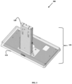
- FIG. 1 is a diagram 100 of a stand 125 of a display holding apparatus 160 configured in a back orientation, according to an example embodiment.
- FIG. 2 is a diagram 200 of the stand 125 of a display holding apparatus 160 configured in a front orientation, according to an example embodiment.
- FIG. 3 is a diagram 300 of a base 110 for the stand 125 of the display holding apparatus 160, according to an example embodiment.
- the base 110 includes six premanufactured screw holes or apertures 111, 112, and 113.
- the back orientation shown in FIG. 1 utilizes screw holes 111 and 112 for purposes of securing a vertical member 120 to the base 110 to form the stand 125.
- the front orientation shown in FIG. 2 utilizes screw holes 112 and 113 for purposes of securing vertical member 120 to base 110 to form the stand 135.
- the vertical member 120 attaches to the base 110 at a right angle to the base 110. Screw holes 112 are common to both the back and front orientations of the stand 125. Corresponding screw holes 121 are shown at the bottom of vertical member 120 in FIG. 5 below.
- the four screw holes 121 of vertical member 120 only align with four of the six screw holes 111, 112, and 113. The ensures that during setup the vertical member 120 can be easily aligned with base 110 and mounted via 4 screws as stand 125 to a top surface of a terminal.
- the four aligned screw holes 121 form a back orientation when aligned to 111 and 112 of base 110. A back orientation is one in which the vertical member 120 sits farther away from the front-edge of the terminal.
- the four aligned screw holes 121 form a front orientation when aligned to 112 and 113 of base 110.
- the front orientation is one in which the vertical member 120 sits closer to the front-edge of the terminal.
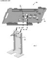
- FIG. 4 is a diagram 400 of a configurable bracket 130 for attaching to the stand of 125 the display holding apparatus 160, according to an example embodiment.
- Bracket 130 includes a plurality of manufactured tabs and screw holes for affixing the bracket 130 to stand 120 and movable plugs for affixing a display 200 (shown in FIG. 10 below).
- Bracket 130 can be configured to orient an attached display in four different orientations: a low portrait orientation (shown in FIGS. 6 and 9 below), a high portrait orientation (shown in FIGS. 5 and 9 below), a low landscape orientation (shown in FIGS. 7 and 9 below), and a high landscape orientation (shown in FIGS. 8 and 9 below).
- the bracket 130 adapted to attach to the vertical member 120 in parallel with the orientation of the vertical member 120 or at a right angle to the vertical member 120.
- the in parallel attachment of the bracket 130 relative to the vertical member 120 is shown in FIGS. 5 and 6 and the bottom two diagrams in FIG. 9 .
- the right-angle attachment of the bracket 130 relative to the vertical member 120 is shown in FIGS. 7 and 8 and the top two diagrams in FIG. 9 .
- FIG. 5 is a diagram 500 illustrating the tab members 135 of the configurable bracket 130 to attach the bracket to the vertical member 120 of the stand 125 for a display 200 in a high portrait orientation, according to an example embodiment.
- Vertical member 120 includes manufactured slots 122, which tabs 135 slide of bracket 130 slide into to configure bracket 130 for holding a display 200 in a high portrait orientation.
- Tabs 134 are inserted into slots 122 to configure bracket 130 for holding a display 100 in a low portrait orientation.
- Bracket 130 can also be rotated 90 degrees relative to vertical member 120 and tabs 132 and 133 inserted into slots 122 for holding a display in high or low landscape orientation.
- Plungers 131 pull out and include a protective rubber tip for inserting edges a display 200 and/or for inserting a back surface of display 200 against bracket 130. When the plungers 131 are released, they push into the sides/back surface of display 200 and hold display 200 firmly against bracket 130.
- FIG. 6 is a diagram 600 illustrating the tab members of the configurable bracket 130 to attach the bracket 130 to the stand 125 for a display 200 in a low portrait orientation, according to an example embodiment.
- Tabs 134 are inserted into slots 122 with tabs 135 beneath tabs 134.
- Tabs 135 fit through other slots 122 such that the bottom of tabs 134 rest on top of vertical member 120 in top slots 122.
- tabs 134 are above tabs 135 which rest on a top of vertical member 120 elevating bracket 130 to a higher vertical position that what is shown in FIG. 6 .
- FIG. 7 is a diagram 700 illustrating the attachment tab members of the configurable bracket 130 to attach the bracket 130 to the stand 125 for a display 200 in a low landscape orientation, according to an example embodiment.
- Bracket 130 is rotated 90 degrees counter clockwise relative to vertical member 120.
- Tabs 133 are inserted into top slots 122 of vertical member 120 to configure a low landscape orientation for any subsequently attached display 200.
- FIG. 8 is a diagram 800 illustrating the tab members of the configurable bracket 130 to attach the bracket 130 to the stand 125 for a display 200 in a high portrait orientation, according to an example embodiment.
- bracket 130 is rotated 90 degrees counter clockwise relative to vertical member 120.
- Tabs 132 are inserted into top slots 122 of vertical member 120 and rests on top of vertical member 120. Notice tabs 133 sit vertically above tabs 132 and are not inserted into any tabs in vertical member 120 this provides a higher vertical position for bracket 130 relative to the vertical member 120 that what was shown in FIG. 7 for the low landscape orientation.
- any subsequently attached display 200 is in a high landscape orientation.
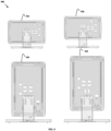
- FIG. 9 are diagrams 800 illustrating the bracket 130 attached to the stand 125 on vertical member 120 for four different display orientations, according to an example embodiment.
- the top rightmost figure shows a low landscape orientation of display apparatus 160 and is configured in the manner discussed above with FIG. 7 .
- the top leftmost figure shows a high landscape orientation of display apparatus 160 and is configured in the manner discussed above with FIG. 8 .
- the bottom rightmost figure shows a low portrait orientation of display apparatus 160 and is configured in the manner discussed above with FIG. 6 .
- the bottom leftmost figure shows a high portrait orientation of display apparatus 160 and is configured in the manner discussed above with FIG. 5 .
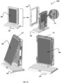
- FIG. 10 are diagrams 1000 illustrating different sized displays 200 held by the display holding apparatus 160, according to an example embodiment.
- An optional display bezel or cover 140 is shown that fits around a periphery of the display 200 attached to bracket 130 of display apparatus 160.
- Diagrams 1000 also illustrate a top tab 137 of bracket 130 under which the display 200 is tucked under. Plungers 131 are pulled out and released causing plungers 131 to push against and hold the sides of display 200 against bracket 130.
- Cover 140 can optionally be placed around the periphery of the display 200.
- the diagrams 1000 of FIG. 10 illustrate the display apparatus 160 configured in a back and low portrait orientation.
- a desired display 200 is attached to display holding apparatus 160 with a power and/or power and data cord 150 from lights, light emitting diodes (LEDs) board, and/or data port of display 200 running underneath and through base 110 of display holding apparatus 160.
- LEDs light emitting diodes
- This allows the power or combined power and data wire 150 to be connected accordingly to the terminal without any visible cord 150 when a bottom side of base 110 is mounted to a top side surface of the terminal.
- the display apparatus 160 can also be in a front orientation (i.e. front edge of stand 120 is closer to the front edge of the terminal) as shown in FIG. 2 or display apparatus 160 can be back orientation (e.g., front edge of stand 120 is farther from the front edge of the terminal) as shown in FIG. 1 .
- front orientation i.e. front edge of stand 120 is closer to the front edge of the terminal
- back orientation e.g., front edge of stand 120 is farther from the front edge of the terminal
- screw holes 111, 112, and 113 in base 110 are manufactured to align with existing screw receptacles (4) in a top surface of a transaction terminal.
- Screw holes 112 align with at least two of the four existing screw receptacles and whatever orientation front or back selected by a customer for the display holding apparatus 160 ensures that at least two of screw holes 111 or two of screw holes 113 align with the remaining two existing screw receptacles.
- apparatus 160 can be used to replace an existing topper of a terminal with just 3 screws and a desired configuration of eight potential configures setup without any screws or any tools being required.
- the display holding apparatus 120 includes an LED board and a panel that sits in front of the LED board to form a display 200 through control of the LEDs on the board illuminated through the panel.
- display holding apparatus is sized to hold a tablet touch computer display 200.
- bracket 130 is resizable to hold different sized displays 200.
- a central rail running horizontally across the bracket 130 and a central rail or pair of side rails running vertically across the bracket can be expand out to increase the size of the bracket horizontally and vertically or fold/tuck in to decrease the size of the bracket horizontally and vertically.
- display holding apparatus 160 can be custom sized to accommodate different sized displays 200.
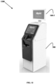
- FIG. 11 are diagrams 1100 of transaction terminals 300 with displays held by the display holding apparatus 160, according to an example embodiment.
- the leftmost figure shows the display apparatus 160-1 configured in a low portrait orientation for the display 200 and a back orientation for stand 120.
- the rightmost figure shows the display apparatus 160-2 configured in a high portrait orientation for the display 200 and a front orientation for stand 120.
- FIG. 12 is another diagram 1200 of a transaction terminal 300 with a display 200 held by the display holding apparatus 160, according to an example embodiment.
- the display 200 is in a high landscape orientation and a back orientation for the stand 120 on top of terminal 300.
- each of the four can also be in either a font orientation for the stand 120 or a back orientation for the stand 120.
- display apparatus 160 there can be any of four different display orientations and each of the four can also be in either a font orientation for the stand 120 or a back orientation for the stand 120.
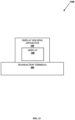
- FIG. 13 is a block diagram of a system 1300 that includes the display holding apparatus 160, according to an example embodiment. It is noted that system 1300 is shown in greatly simplified form with only those components necessary for understanding the embodiments provided. Thus, there can be more or less components without departing from the teachings provided herein.
- System 1300 includes a transaction terminal 300, display holding apparatus 160, and display 200.
- the display holding apparatus 160 includes a base 110, a vertical member 120, and a bracket 130.
- display holding apparatus 160 includes a display cover 140.
- display holding apparatus 160 includes an LED light board and a light panel.
- the display 200 is a lighted sign with lights and one or more covers/panels, a monitor, a touch monitor, or a tablet.
- the vertical member 120 is attachable to base 110 in a front orientation or a back orientation.
- the bracket 130 is attachable to the vertical member 120 in a high landscape orientation, a low landscape orientation, a high portrait orientation, or a low portrait orientation.
- display holding apparatus 160 can be configured in 8 different configurations.
- the apparatus 160 when holding a specific display 200 forms a display system.
Landscapes
- Engineering & Computer Science (AREA)
- General Engineering & Computer Science (AREA)
- Physics & Mathematics (AREA)
- General Physics & Mathematics (AREA)
- Theoretical Computer Science (AREA)
- Mechanical Engineering (AREA)
- Computer Hardware Design (AREA)
- Human Computer Interaction (AREA)
- Devices For Indicating Variable Information By Combining Individual Elements (AREA)
Abstract
Description
- Displays and/or illuminated signs come in a variety of different shapes, sizes, and capabilities. Displays/signs are also popular for advertisements or for drawing a customer's attention to another device, such as an automated teller machine (ATM). Any sign/display affixed to a top surface of an ATM is often referred to as a "topper."
- Current designs of ATM toppers are bulky, heavy, and inflexible. There exists just a few design options and each option is restricted to a designated position and orientation on the top surface of the ATM. Existing toppers are also time consuming to assemble and are usually shipped to a retail site separately from the ATM.
- In various embodiments, a configurable display holding apparatus and system are presented. The apparatus includes a base, a vertical member, and a bracket. The vertical member is attached to the base to form a stand. The bracket attaches to the vertical member of the stand in a plurality of orientations. A display attaches to the bracket in the bracket's configured orientation with the vertical member of the stand.
- According to a first aspect of the present invention there is provided a display holding apparatus, comprising: a base; a vertical member attachable and detachable to the base in first orientations; a stand comprising the vertical member attached to the base in a certain first orientation; and a bracket attachable and detachable to the vertical member of the stand along a first side of the bracket in second orientations, wherein the bracket, along a second side, is adapted to hold a display in a certain second orientation.
- Aptly, the display holding apparatus further comprises a display cover adapted to fit over a periphery of the display and snap onto a portion of the bracket.
- Aptly, the base comprises an aperture adapted to allow at least one cord associated with the display to pass through the aperture to one or more of a power supply and a device.
- Aptly, first orientations comprise a front orientation and a back orientation, wherein the front orientation includes the vertical member being attached closer to a front edge of the base than that which is associated with the back orientation.
- Aptly, the base includes three pairs of screw holes, a first pair of screw holes associated with the front orientation, a second pair of screw holes associated with the back orientation, and a third pair of screw holes associated with both the first orientation and the second orientation.
- Aptly, the second orientations includes a first height landscape orientation for any attached display, a second height landscape orientation that is higher than the first height landscape orientation, a first height portrait orientation for any attached display, and a second height portrait orientation that is higher than the first height portrait orientation.
- Aptly, the vertical member of the stand includes slots.
- Aptly, the first side of the bracket includes a plurality of tabs.
- Aptly, a given pair of the tabs are configured to be inserted into the slots to form a given second orientation.
- Aptly, at least one pair of the tabs align for insertion into the slots when the bracket is rotated 90 degrees from an original vertical orientation of the bracket.
- According to a second aspect of the present invention there is provided a system, comprising: a transaction terminal; and a display holding apparatus, comprising: a stand comprising a base and a vertical member attached to the base; and a bracket comprising a plurality of tabs along a first side of the bracket, wherein the tabs are adapted to be inserted into slots of the vertical member to arrange the bracket on the vertical member in configured display orientations, and wherein the bracket comprises plungers adapted to hold a display against a second side of the bracket; wherein the display holding apparatus is adapted to be mounted to a top surface of the transaction terminal.
- Aptly, the vertical member is adapted to attach to the base to form the stand in two different orientations that comprises a first orientation with the vertical member closer to a front edge of the base and a front edge of the transaction terminal than that which is associated with a second orientation where the vertical member is farther away from the front edges of the base and the transaction terminal.
- Aptly, the vertical member is attached through screws inserted through holes in a bottom of the vertical member, through holes in the base, and into holes on the top surface of the transaction terminal to form the stand mounted to the transaction terminal.
- Aptly, the holes in the bottom of the vertical member align with the holes in the base in both the first orientation and the second orientation.
- Aptly, the display holding apparatus further includes a display cover that fits over a periphery of the display and snaps into the bracket.
- Aptly, the base includes an aperture adapted to pass a power cord, a data cord, or a combination power and data cord from the display into an aperture in the top surface of the transaction terminal to connect and power the display held in the display holding apparatus and mounted to the top surface of the transaction terminal.
- Aptly, the display comprises a light emitting diode (LED) board and a light panel covering the LED board.
- Aptly, the display comprises a table computer, a digital sign, or a smart monitor.
- According to a third aspect of the present invention there is provided a display system, comprising: a display; a display holding apparatus comprising: a stand that includes a base and a vertical member attached to the base at a right angle; a bracket adapted to be attached to the vertical member in different orientations, wherein in first orientations the bracket is vertical and parallel to the vertical member, wherein in second orientations the bracket is perpendicular to the vertical member; and a display cover adapted to fit around a periphery of the display and snap into the bracket, wherein a first side of the bracket is adapted to attach to the vertical member in the first orientations and the second orientations, and wherein a back side of the display is adapted to be fixedly held against a second side of the bracket.
- Aptly, the vertical member is adapted to attach to the base at the right angle in two different orientations.
-
FIG. 1 is a diagram of a stand for a display holding apparatus configured in a back orientation, according to an example embodiment. -
FIG. 2 is a diagram of the stand for a display holding apparatus configured in a front orientation, according to an example embodiment. -
FIG. 3 is a diagram of a base for the stand of the display holding apparatus, according to an example embodiment. -
FIG. 4 is a diagram of a configurable bracket for attaching to the stand of the display holding apparatus, according to an example embodiment. -
FIG. 5 is a diagram illustrating the attachment members of the configurable bracket to attach the bracket to the stand for a display in a high portrait orientation, according to an example embodiment. -
FIG. 6 is a diagram illustrating the attachment members of the configurable bracket to attach the bracket to the stand for a display in a low portrait orientation, according to an example embodiment. -
FIG. 7 is a diagram illustrating the attachment members of the configurable bracket to attach the bracket to the stand for a display in a low landscape orientation, according to an example embodiment. -
FIG. 8 is a diagram illustrating the attachment members of the configurable bracket to attach the bracket to the stand for a display in a high landscape orientation, according to an example embodiment. -
FIG. 9 are diagrams illustrating the bracket attached to the stand for four different display orientations, according to an example embodiment. -
FIG. 10 are diagrams illustrating different sized displays held by the display holding apparatus, according to an example embodiment. -
FIG. 11 are diagrams of transaction terminals with displays held by the display holding apparatus, according to an example embodiment. -
FIG. 12 is another diagram of a transaction terminal with a display held by the display holding apparatus, according to an example embodiment. -
FIG. 13 is a block diagram of a system that includes the display holding apparatus, according to an example embodiment. - As stated above, most transaction terminals, such as ATMs, include a topper affixed to a top surface of the ATMs for purposes of providing customer advertisements to customers passing by and/or for purposes of enticing customers to perform transactions on the ATMs. In most cases, these toppers are just lighted signs with fixed and rigid designs attached to the top surface of the ATMs. The dimensions, orientations, and position of the toppers on the ATM are not configurable. More often than not, the retailer selects a topper design and then has a sign panel custom made in the size and dimensions supported by the topper design; a light behind or in the panel provides the retailer's advertisement. Consequently, many toppers appear out of place with the overall aesthetic design of the ATM or the surroundings of where the ATM is located.
- Customers frequent transaction terminals to perform transactions, such as to purchase an item, withdraw currency, deposit currency, place an order with a retailer, review a status of an order, make a reservation, check-in to an establishment, etc. Accordingly, the attention of a customer is captured during a transaction at a terminal. This makes for prime real estate for retailers to pitch their products and services or to establish a retailer's brand with the customer. Additionally, displays of the terminals are often intentionally obfuscated to passers-by so that a customer performing a transaction has privacy; thus, the space above the terminal display can also be used to attract a customer to the terminal for a transaction.
- The teachings provided address these issues by providing a configurable display holder apparatus and system. The apparatus can be configured to hold a lighted panel display or an intelligent display in eight different configurations, four for portrait display orientation and four for landscape display orientation. The apparatus includes a minimal amount of components and can be assembled in minutes. Moreover, the apparatus can be reconfigured for a different display orientation from an existing display orientation in minutes. The components of the apparatus are less than existing components of existing industry toppers; weigh less resulting in reduced shipping expenses; and can be setup and/or reconfigured without any skilled technician in minutes.
- As used herein a "topper" is a device that includes panels which are lighted to produce a visual branding or advertisement on top of a transaction terminal. A "transaction terminal" is a self-service terminal (SST), an automated teller machine (ATM), or a kiosk. A "display" can include a topper with lighted panels to visually convey a message or a branding, a monitor, a digital sign, or an independent processing device integrated into the monitor (e.g., a tablet, touch-based monitor, smart/intelligent monitor/display, etc.).
- The display apparatus 160 (shown in
FIG. 10 below) includes a stand 125 (shown inFIG. 1 below), abracket 130, a bracket and display cover 140 (shown inFIG. 10 below), and optionally a display 200 (shown inFIG. 10 below).FIG. 1 is a diagram 100 of astand 125 of adisplay holding apparatus 160 configured in a back orientation, according to an example embodiment.FIG. 2 is a diagram 200 of thestand 125 of adisplay holding apparatus 160 configured in a front orientation, according to an example embodiment.FIG. 3 is a diagram 300 of abase 110 for thestand 125 of thedisplay holding apparatus 160, according to an example embodiment. - The
base 110 includes six premanufactured screw holes orapertures FIG. 1 utilizes screw holes 111 and 112 for purposes of securing avertical member 120 to the base 110 to form thestand 125. The front orientation shown inFIG. 2 utilizes screw holes 112 and 113 for purposes of securingvertical member 120 tobase 110 to form the stand 135. Thevertical member 120 attaches to the base 110 at a right angle to thebase 110. Screw holes 112 are common to both the back and front orientations of thestand 125. Corresponding screw holes 121 are shown at the bottom ofvertical member 120 inFIG. 5 below. - The four
screw holes 121 ofvertical member 120 only align with four of the sixscrew holes vertical member 120 can be easily aligned withbase 110 and mounted via 4 screws asstand 125 to a top surface of a terminal. The four aligned screw holes 121 form a back orientation when aligned to 111 and 112 ofbase 110. A back orientation is one in which thevertical member 120 sits farther away from the front-edge of the terminal. The four aligned screw holes 121 form a front orientation when aligned to 112 and 113 ofbase 110. The front orientation is one in which thevertical member 120 sits closer to the front-edge of the terminal. -
FIG. 4 is a diagram 400 of aconfigurable bracket 130 for attaching to the stand of 125 thedisplay holding apparatus 160, according to an example embodiment.Bracket 130 includes a plurality of manufactured tabs and screw holes for affixing thebracket 130 to stand 120 and movable plugs for affixing a display 200 (shown inFIG. 10 below).Bracket 130 can be configured to orient an attached display in four different orientations: a low portrait orientation (shown inFIGS. 6 and9 below), a high portrait orientation (shown inFIGS. 5 and9 below), a low landscape orientation (shown inFIGS. 7 and9 below), and a high landscape orientation (shown inFIGS. 8 and9 below). Thebracket 130 adapted to attach to thevertical member 120 in parallel with the orientation of thevertical member 120 or at a right angle to thevertical member 120. The in parallel attachment of thebracket 130 relative to thevertical member 120 is shown inFIGS. 5 and6 and the bottom two diagrams inFIG. 9 . The right-angle attachment of thebracket 130 relative to thevertical member 120 is shown inFIGS. 7 and8 and the top two diagrams inFIG. 9 . -
FIG. 5 is a diagram 500 illustrating the tab members 135 of theconfigurable bracket 130 to attach the bracket to thevertical member 120 of thestand 125 for adisplay 200 in a high portrait orientation, according to an example embodiment.Vertical member 120 includes manufacturedslots 122, which tabs 135 slide ofbracket 130 slide into to configurebracket 130 for holding adisplay 200 in a high portrait orientation. -
Tabs 134 are inserted intoslots 122 to configurebracket 130 for holding adisplay 100 in a low portrait orientation.Bracket 130 can also be rotated 90 degrees relative tovertical member 120 andtabs slots 122 for holding a display in high or low landscape orientation.Plungers 131 pull out and include a protective rubber tip for inserting edges adisplay 200 and/or for inserting a back surface ofdisplay 200 againstbracket 130. When theplungers 131 are released, they push into the sides/back surface ofdisplay 200 and holddisplay 200 firmly againstbracket 130. -
FIG. 6 is a diagram 600 illustrating the tab members of theconfigurable bracket 130 to attach thebracket 130 to thestand 125 for adisplay 200 in a low portrait orientation, according to an example embodiment.Tabs 134 are inserted intoslots 122 with tabs 135 beneathtabs 134. Tabs 135 fit throughother slots 122 such that the bottom oftabs 134 rest on top ofvertical member 120 intop slots 122. This lowersbracket 130 below a vertical height ofbracket 130 from that which was shown inFIG. 5 for the high portrait orientation. In the high portrait orientation as shown inFIG. 5 tabs 134 are above tabs 135 which rest on a top ofvertical member 120 elevatingbracket 130 to a higher vertical position that what is shown inFIG. 6 . -
FIG. 7 is a diagram 700 illustrating the attachment tab members of theconfigurable bracket 130 to attach thebracket 130 to thestand 125 for adisplay 200 in a low landscape orientation, according to an example embodiment.Bracket 130 is rotated 90 degrees counter clockwise relative tovertical member 120.Tabs 133 are inserted intotop slots 122 ofvertical member 120 to configure a low landscape orientation for any subsequently attacheddisplay 200. -
FIG. 8 is a diagram 800 illustrating the tab members of theconfigurable bracket 130 to attach thebracket 130 to thestand 125 for adisplay 200 in a high portrait orientation, according to an example embodiment. Once againbracket 130 is rotated 90 degrees counter clockwise relative tovertical member 120.Tabs 132 are inserted intotop slots 122 ofvertical member 120 and rests on top ofvertical member 120.Notice tabs 133 sit vertically abovetabs 132 and are not inserted into any tabs invertical member 120 this provides a higher vertical position forbracket 130 relative to thevertical member 120 that what was shown inFIG. 7 for the low landscape orientation. Whentabs 132 are inserted intotop slots 122 ofvertical member 120 any subsequently attacheddisplay 200 is in a high landscape orientation. -
FIG. 9 are diagrams 800 illustrating thebracket 130 attached to thestand 125 onvertical member 120 for four different display orientations, according to an example embodiment. The top rightmost figure shows a low landscape orientation ofdisplay apparatus 160 and is configured in the manner discussed above withFIG. 7 . The top leftmost figure shows a high landscape orientation ofdisplay apparatus 160 and is configured in the manner discussed above withFIG. 8 . The bottom rightmost figure shows a low portrait orientation ofdisplay apparatus 160 and is configured in the manner discussed above withFIG. 6 . The bottom leftmost figure shows a high portrait orientation ofdisplay apparatus 160 and is configured in the manner discussed above withFIG. 5 . -
FIG. 10 are diagrams 1000 illustrating differentsized displays 200 held by thedisplay holding apparatus 160, according to an example embodiment. An optional display bezel or cover 140 is shown that fits around a periphery of thedisplay 200 attached tobracket 130 ofdisplay apparatus 160. Diagrams 1000 also illustrate atop tab 137 ofbracket 130 under which thedisplay 200 is tucked under.Plungers 131 are pulled out and released causingplungers 131 to push against and hold the sides ofdisplay 200 againstbracket 130. Cover 140 can optionally be placed around the periphery of thedisplay 200. The diagrams 1000 ofFIG. 10 illustrate thedisplay apparatus 160 configured in a back and low portrait orientation. - A desired
display 200 is attached to display holdingapparatus 160 with a power and/or power anddata cord 150 from lights, light emitting diodes (LEDs) board, and/or data port ofdisplay 200 running underneath and throughbase 110 ofdisplay holding apparatus 160. This allows the power or combined power anddata wire 150 to be connected accordingly to the terminal without anyvisible cord 150 when a bottom side ofbase 110 is mounted to a top side surface of the terminal. - It is noted that for each of the four discussed display apparatus orientations, the
display apparatus 160 can also be in a front orientation (i.e. front edge ofstand 120 is closer to the front edge of the terminal) as shown inFIG. 2 ordisplay apparatus 160 can be back orientation (e.g., front edge ofstand 120 is farther from the front edge of the terminal) as shown inFIG. 1 . Thus, there are 8 possible configurations achievable withdisplay apparatus 160 via just three components forbase 110, stand 120, andbracket 130 or via four components foroptional display cover 140. - In an embodiment, four of the six
screw holes base 110 are manufactured to align with existing screw receptacles (4) in a top surface of a transaction terminal. Screw holes 112 align with at least two of the four existing screw receptacles and whatever orientation front or back selected by a customer for thedisplay holding apparatus 160 ensures that at least two of screw holes 111 or two of screw holes 113 align with the remaining two existing screw receptacles. Thus,apparatus 160 can be used to replace an existing topper of a terminal with just 3 screws and a desired configuration of eight potential configures setup without any screws or any tools being required. - In an embodiment, the
display holding apparatus 120 includes an LED board and a panel that sits in front of the LED board to form adisplay 200 through control of the LEDs on the board illuminated through the panel. In an embodiment, display holding apparatus is sized to hold a tablettouch computer display 200. - In an embodiment,
bracket 130 is resizable to hold differentsized displays 200. For example a central rail running horizontally across thebracket 130 and a central rail or pair of side rails running vertically across the bracket can be expand out to increase the size of the bracket horizontally and vertically or fold/tuck in to decrease the size of the bracket horizontally and vertically. In this way,display holding apparatus 160 can be custom sized to accommodate differentsized displays 200. -
FIG. 11 are diagrams 1100 oftransaction terminals 300 with displays held by thedisplay holding apparatus 160, according to an example embodiment. The leftmost figure shows the display apparatus 160-1 configured in a low portrait orientation for thedisplay 200 and a back orientation forstand 120. The rightmost figure shows the display apparatus 160-2 configured in a high portrait orientation for thedisplay 200 and a front orientation forstand 120. Although not shown, there can also be a low portrait orientation in a front orientation for the stand and a high portrait orientation in a back orientation fromstand 120. -
FIG. 12 is another diagram 1200 of atransaction terminal 300 with adisplay 200 held by thedisplay holding apparatus 160, according to an example embodiment. Thedisplay 200 is in a high landscape orientation and a back orientation for thestand 120 on top ofterminal 300. Although not shown, there can also be a high landscape orientation fordisplay 200 in a front orientation for thestand 120, a low landscape orientation fordisplay 200 in a front orientation for thestand 120, and a low landscape orientation fordisplay 200 in a back orientation for thestand 120. - Again, there can be any of four different display orientations and each of the four can also be in either a font orientation for the
stand 120 or a back orientation for thestand 120. Thus, there are eight different configurations achievable withdisplay apparatus 160. -
FIG. 13 is a block diagram of asystem 1300 that includes thedisplay holding apparatus 160, according to an example embodiment. It is noted thatsystem 1300 is shown in greatly simplified form with only those components necessary for understanding the embodiments provided. Thus, there can be more or less components without departing from the teachings provided herein. -
System 1300 includes atransaction terminal 300,display holding apparatus 160, anddisplay 200. Thedisplay holding apparatus 160 includes abase 110, avertical member 120, and abracket 130. In an embodiment,display holding apparatus 160 includes adisplay cover 140. In an embodiment,display holding apparatus 160 includes an LED light board and a light panel. In an embodiment, thedisplay 200 is a lighted sign with lights and one or more covers/panels, a monitor, a touch monitor, or a tablet. - The
vertical member 120 is attachable to base 110 in a front orientation or a back orientation. Thebracket 130 is attachable to thevertical member 120 in a high landscape orientation, a low landscape orientation, a high portrait orientation, or a low portrait orientation. Thus,display holding apparatus 160 can be configured in 8 different configurations. - In an embodiment, the
apparatus 160 when holding aspecific display 200 forms a display system. - The above description is illustrative, and not restrictive. Many other embodiments will be apparent to those of skill in the art upon reviewing the above description. The scope of embodiments should therefore be determined with reference to the appended claims, along with the full scope of equivalents to which such claims are entitled.
- In the foregoing description of the embodiments, various features are grouped together in a single embodiment for the purpose of streamlining the disclosure. This method of disclosure is not to be interpreted as reflecting that the claimed embodiments have more features than are expressly recited in each claim. Rather, as the following claims reflect, inventive subject matter lies in less than all features of a single disclosed embodiment. Thus, the following claims are hereby incorporated into the Description of the Embodiments, with each claim standing on its own as a separate exemplary embodiment.
- Throughout the description and claims of this specification, the words "comprise" and "contain" and variations of them mean "including but not limited to" and they are not intended to (and do not) exclude other moieties, additives, components, integers or steps. Throughout the description and claims of this specification, the singular encompasses the plural unless the context otherwise requires. In particular, where the indefinite article is used, the specification is to be understood as contemplating plurality as well as singularity, unless the context requires otherwise.
- Features, integers, characteristics or groups described in conjunction with a particular aspect, embodiment or example of the invention are to be understood to be applicable to any other aspect, embodiment or example described herein unless incompatible therewith. All of the features disclosed in this specification (including any accompanying claims, abstract and drawings), and/or all of the steps of any method or process so disclosed, may be combined in any combination, except combinations where at least some of the features and/or steps are mutually exclusive. The invention is not restricted to any details of any foregoing embodiments. The invention extends to any novel one, or novel combination, of the features disclosed in this specification (including any accompanying claims, abstract and drawings), or to any novel one, or any novel combination, of the steps of any method or process so disclosed.
- The reader's attention is directed to all papers and documents which are filed concurrently with or previous to this specification in connection with this application and which are open to public inspection with this specification, and the contents of all such papers and documents are incorporated herein by reference.
Claims (15)
- A display holding apparatus, comprising:a base;a vertical member attachable and detachable to the base in first orientations;a stand comprising the vertical member attached to the base in a certain first orientation; anda bracket attachable and detachable to the vertical member of the stand along a first side of the bracket in second orientations, wherein the bracket, along a second side, is adapted to hold a display in a certain second orientation.
- The display holding apparatus of claim 1 further comprising, a display cover adapted to fit over a periphery of the display and snap onto a portion of the bracket.
- The display holding apparatus of claim 1, wherein the base comprises an aperture adapted to allow at least one cord associated with the display to pass through the aperture to one or more of a power supply and a device.
- The display holding apparatus of claim 1, wherein first orientations comprise a front orientation and a back orientation, wherein the front orientation includes the vertical member being attached closer to a front edge of the base than that which is associated with the back orientation.
- The display holding apparatus of claim 4, wherein the base includes three pairs of screw holes, a first pair of screw holes associated with the front orientation, a second pair of screw holes associated with the back orientation, and a third pair of screw holes associated with both the first orientation and the second orientation.
- The display holding apparatus of claim 1, wherein the second orientations includes a first height landscape orientation for any attached display, a second height landscape orientation that is higher than the first height landscape orientation, a first height portrait orientation for any attached display, and a second height portrait orientation that is higher than the first height portrait orientation.
- The display holding apparatus of claim 1, wherein at least one pair of the tabs align for insertion into the slots when the bracket is rotated 90 degrees from an original vertical orientation of the bracket.
- A system, comprising:a transaction terminal; anda display holding apparatus, comprising:a stand comprising a base and a vertical member attached to the base; anda bracket comprising a plurality of tabs along a first side of the bracket, wherein the tabs are adapted to be inserted into slots of the vertical member to arrange the bracket on the vertical member in configured display orientations, and wherein the bracket comprises plungers adapted to hold a display against a second side of the bracket;wherein the display holding apparatus is adapted to be mounted to a top surface of the transaction terminal.
- The system of claim 8, wherein the vertical member is adapted to attach to the base to form the stand in two different orientations that comprises a first orientation with the vertical member closer to a front edge of the base and a front edge of the transaction terminal than that which is associated with a second orientation where the vertical member is farther away from the front edges of the base and the transaction terminal.
- The system of claim 9, wherein the vertical member is attached through screws inserted through holes in a bottom of the vertical member, through holes in the base, and into holes on the top surface of the transaction terminal to form the stand mounted to the transaction terminal.
- The system of claim 10, wherein the holes in the bottom of the vertical member align with the holes in the base in both the first orientation and the second orientation.
- The system of claim 8, wherein the display holding apparatus further includes a display cover that fits over a periphery of the display and snaps into the bracket.
- The system of claim 8, wherein the base includes an aperture adapted to pass a power cord, a data cord, or a combination power and data cord from the display into an aperture in the top surface of the transaction terminal to connect and power the display held in the display holding apparatus and mounted to the top surface of the transaction terminal.
- A display system, comprising:a display;a display holding apparatus comprising:a stand that includes a base and a vertical member attached to the base at a right angle;a bracket adapted to be attached to the vertical member in different orientations, wherein in first orientations the bracket is vertical and parallel to the vertical member, wherein in second orientations the bracket is perpendicular to the vertical member; anda display cover adapted to fit around a periphery of the display and snap into the bracket, wherein a first side of the bracket is adapted to attach to the vertical member in the first orientations and the second orientations, and wherein a back side of the display is adapted to be fixedly held against a second side of the bracket.
- The display system of claim 14, wherein the vertical member is adapted to attach to the base at the right angle in two different orientations.
Applications Claiming Priority (1)
| Application Number | Priority Date | Filing Date | Title |
|---|---|---|---|
| US18/103,650 US12474733B2 (en) | 2023-01-31 | 2023-01-31 | Configurable display holding apparatus and system |
Publications (2)
| Publication Number | Publication Date |
|---|---|
| EP4411197A1 true EP4411197A1 (en) | 2024-08-07 |
| EP4411197B1 EP4411197B1 (en) | 2026-04-29 |
Family
ID=89224794
Family Applications (1)
| Application Number | Title | Priority Date | Filing Date |
|---|---|---|---|
| EP23218821.9A Active EP4411197B1 (en) | 2023-01-31 | 2023-12-20 | Configurable display holding apparatus and system |
Country Status (2)
| Country | Link |
|---|---|
| US (2) | US12474733B2 (en) |
| EP (1) | EP4411197B1 (en) |
Citations (2)
| Publication number | Priority date | Publication date | Assignee | Title |
|---|---|---|---|---|
| KR20090027099A (en) * | 2007-09-11 | 2009-03-16 | (주)에이치지엔에스 | ATM terminal with advertising function |
| US20110205032A1 (en) * | 2010-02-25 | 2011-08-25 | Toshiba Tec Kabushiki Kaisha | Display device |
Family Cites Families (55)
| Publication number | Priority date | Publication date | Assignee | Title |
|---|---|---|---|---|
| JP3322021B2 (en) * | 1994-08-22 | 2002-09-09 | カシオ計算機株式会社 | Information equipment |
| DE69824289T2 (en) * | 1998-09-21 | 2005-06-16 | Hewlett-Packard Development Co., L.P., Houston | Rotatable display device |
| US6189842B1 (en) * | 1999-06-21 | 2001-02-20 | Palo Alto Design Group | Tilt and swivel adjustment of flat panel display having detents for landscape and portrait positions and kickout for preventing contact between flat panel display and base |
| JP2001042779A (en) * | 1999-07-29 | 2001-02-16 | Toshiba Corp | Personal computer |
| US6522529B1 (en) * | 2000-05-22 | 2003-02-18 | Vivek R. Huilgol | Rotatable computer display apparatus and method |
| US6418010B1 (en) * | 2000-08-11 | 2002-07-09 | Gateway, Inc. | Convertible flat panel display hanging support |
| CA2386576C (en) * | 2001-05-15 | 2009-07-21 | Research In Motion Limited | Information system with detachable information module |
| US20040118987A1 (en) * | 2002-12-20 | 2004-06-24 | Bendix Commercial Vehicle Systems Llc | Flat panel display mounting bracket |
| JP3665063B2 (en) * | 2003-01-09 | 2005-06-29 | シャープ株式会社 | Thin display device and method for removing display unit |
| TWI221954B (en) * | 2003-08-07 | 2004-10-11 | Benq Corp | Flat panel display |
| US7070156B2 (en) * | 2003-10-30 | 2006-07-04 | Jung Huang Liao | Adjustable securing rack for plasma TV |
| SE526502C2 (en) * | 2004-03-18 | 2005-09-27 | Rapidly Happy Ab | Device for wall mounting of monitors |
| GB0412092D0 (en) * | 2004-05-29 | 2004-06-30 | Benn Alastair | Flat screen television unit |
| USD504426S1 (en) * | 2004-06-08 | 2005-04-26 | Flextronics International Usa, Inc. | Desktop computer |
| US7082028B2 (en) * | 2004-07-08 | 2006-07-25 | Swivel It, Inc. | Rotatable computer display apparatus and method |
| US7708240B2 (en) * | 2004-07-29 | 2010-05-04 | Hewlett-Packard Development Company, L.P. | Computer docking system |
| US7272892B2 (en) * | 2004-12-30 | 2007-09-25 | Mondo Systems, Inc. | Device and method for arranging a flat panel display |
| US7233488B2 (en) * | 2005-01-03 | 2007-06-19 | Hannspree, Inc. | Display device having a retractable supporting unit |
| US7277239B2 (en) * | 2005-01-28 | 2007-10-02 | Carnevali Jeffrey D | Magnification mechanism for viewing an electronic display |
| US8596599B1 (en) * | 2005-03-29 | 2013-12-03 | Xybix Systems Incorporated | Apparatus for mounting a plurality of monitors having adjustable distance to a viewer |
| US7430113B2 (en) * | 2005-07-12 | 2008-09-30 | Dell Products L.P. | System and method for display stand height adjustment |
| US20070258196A1 (en) * | 2006-05-05 | 2007-11-08 | Designer Av Equipment | Flat panel television mounting assembly, and method |
| US7646593B2 (en) * | 2007-02-25 | 2010-01-12 | Vladislava Smejkalova | Adjustable laptop monitor apparatus |
| US20080259551A1 (en) * | 2007-04-20 | 2008-10-23 | Gotive A.S. | Modular computing device |
| US8456808B2 (en) * | 2007-09-06 | 2013-06-04 | Milestone Av Technologies Llc | Display wall mount with elastomeric spring latch and post-installation height adjustment and leveling feature |
| US7845605B2 (en) * | 2008-03-17 | 2010-12-07 | Bose Corporation | Multimedia device bracket |
| WO2009124061A1 (en) * | 2008-04-02 | 2009-10-08 | Peerless Industries, Inc. | Display mounting system |
| JP4709324B2 (en) * | 2008-04-10 | 2011-06-22 | 富士通株式会社 | Support structure and electronic equipment |
| US8172186B2 (en) * | 2009-07-17 | 2012-05-08 | Aopen Incorporated | Display support seat |
| US20110011996A1 (en) * | 2009-07-17 | 2011-01-20 | Aopen Incorporated | Angle adjusting device for display |
| US20110012001A1 (en) * | 2009-07-17 | 2011-01-20 | Aopen Incorporated | Angle adjusting device for display |
| US8467183B2 (en) * | 2010-01-28 | 2013-06-18 | Cruxcase, Llc | Tablet computer case and associated methods |
| US8467179B2 (en) * | 2010-01-28 | 2013-06-18 | Cruxcase, Llc | Tablet computer case and associated methods |
| US8749963B2 (en) * | 2010-03-15 | 2014-06-10 | Over The Sun, Llc | Housing for slate tablet computer |
| US8230992B2 (en) * | 2010-03-15 | 2012-07-31 | Speculative Product Design, Llc | Tablet computer case for multiple viewing orientations |
| USD626129S1 (en) * | 2010-05-12 | 2010-10-26 | Lutz Frank G | Portable eBook and electronic device carrier |
| BR112012028204A2 (en) * | 2010-06-07 | 2016-12-06 | Targus Group Internat Inc | portable electronic device wrap accessories and related systems and methods |
| USD650783S1 (en) * | 2010-07-30 | 2011-12-20 | Creston Electronics Inc. | Tablet dock |
| USD650784S1 (en) * | 2010-08-04 | 2011-12-20 | Crestron Electronics Inc. | Tablet wall dock |
| USD643842S1 (en) * | 2011-04-18 | 2011-08-23 | inNuevo, LLC | Docking station |
| US8379382B2 (en) * | 2011-04-18 | 2013-02-19 | inNuevo, LLC | Docking station |
| US9292043B2 (en) * | 2011-06-06 | 2016-03-22 | Hewlett-Packard Development Company, L.P. | Flat panel monitor stands |
| US8619416B2 (en) * | 2011-10-11 | 2013-12-31 | Hewlett-Packard Development Company, L.P. | Dual-orientation docking apparatus |
| CN103999013B (en) * | 2011-10-14 | 2017-04-05 | 爱格升有限公司 | Flat board installing arm system and method |
| US8640868B2 (en) * | 2012-01-13 | 2014-02-04 | John O'Dowd | Case assembly and method for covering and protecting a portable device |
| US9570925B2 (en) * | 2012-12-05 | 2017-02-14 | Nokia Technologies Oy | Apparatus for selectively supporting and charging an electronic device in a portrait position and a landscape position |
| US9760116B2 (en) * | 2012-12-05 | 2017-09-12 | Mobile Tech, Inc. | Docking station for tablet device |
| TW201510404A (en) * | 2013-09-13 | 2015-03-16 | Hon Hai Prec Ind Co Ltd | Bracket |
| WO2017073872A1 (en) * | 2015-10-26 | 2017-05-04 | Lg Electronics Inc. | Display device |
| US9727092B1 (en) * | 2016-02-02 | 2017-08-08 | Intel Corporation | Torque hinge for a computing device |
| US10101770B2 (en) * | 2016-07-29 | 2018-10-16 | Mobile Tech, Inc. | Docking system for portable computing device in an enclosure |
| USD882570S1 (en) * | 2018-01-03 | 2020-04-28 | Facebook, Inc. | Electronic display device |
| US10540857B1 (en) * | 2018-06-29 | 2020-01-21 | Ncr Corporation | Multifunction interface device for a self-service terminal |
| US10863834B2 (en) * | 2018-06-29 | 2020-12-15 | Ncr Corporation | Interactive tablet and shelf |
| USD1029836S1 (en) * | 2022-05-27 | 2024-06-04 | Ncr Corporation | Terminal |
-
2023
- 2023-01-31 US US18/103,650 patent/US12474733B2/en active Active
- 2023-12-20 EP EP23218821.9A patent/EP4411197B1/en active Active
-
2025
- 2025-05-20 US US19/213,060 patent/US20250278114A1/en active Pending
Patent Citations (2)
| Publication number | Priority date | Publication date | Assignee | Title |
|---|---|---|---|---|
| KR20090027099A (en) * | 2007-09-11 | 2009-03-16 | (주)에이치지엔에스 | ATM terminal with advertising function |
| US20110205032A1 (en) * | 2010-02-25 | 2011-08-25 | Toshiba Tec Kabushiki Kaisha | Display device |
Also Published As
| Publication number | Publication date |
|---|---|
| US20240255986A1 (en) | 2024-08-01 |
| US12474733B2 (en) | 2025-11-18 |
| US20250278114A1 (en) | 2025-09-04 |
| EP4411197B1 (en) | 2026-04-29 |
Similar Documents
| Publication | Publication Date | Title |
|---|---|---|
| EP2800499B1 (en) | Display shelf modules with projectors for displaying product information and modular shelving systems comprising the same | |
| EP2784768B1 (en) | Showcase system having transparent display panel and operating method thereof | |
| US11468420B2 (en) | Digital module built-in desk | |
| US8172096B2 (en) | Shelf for a shelving unit | |
| US20230136763A1 (en) | Dynamic display for terminal lane indicator | |
| EP2327339A1 (en) | Display shelf and display shelf system | |
| US20140139548A1 (en) | Retail digital signage | |
| US20180317671A1 (en) | Food service equipment and systems | |
| TWI470592B (en) | Signage apparatus having simple magnet-based structure for ease of modification | |
| US20190191894A1 (en) | Led frame structure for a kiosk | |
| EP3188110A1 (en) | Display-integrated information display system | |
| EP4411197B1 (en) | Configurable display holding apparatus and system | |
| US8589232B2 (en) | Advertising method and system with use of multi-screened computer monitor units | |
| US20240086879A1 (en) | Accessibility self-service terminal (sst) with devices and modules for custom configurations | |
| US10980361B1 (en) | Shelf alignment guide system | |
| CN206774149U (en) | Product display table | |
| CN104517369A (en) | Self-service educational administration service terminal | |
| CN212088965U (en) | Intelligent commodity display rack | |
| KR200490565Y1 (en) | Goods display unit for display stand | |
| US7178732B1 (en) | Bar code reader with image display system | |
| CN209058546U (en) | Product display cabinet | |
| CN109754522A (en) | A kind of automatic vending machine splicing linkage display control method | |
| KR20150001630U (en) | Display stand for mobile device | |
| EP1284479A1 (en) | Information display system | |
| RU126857U1 (en) | INTERACTIVE INFORMATION AND ADVERTISING SYSTEM OF Catering |
Legal Events
| Date | Code | Title | Description |
|---|---|---|---|
| PUAI | Public reference made under article 153(3) epc to a published international application that has entered the european phase |
Free format text: ORIGINAL CODE: 0009012 |
|
| STAA | Information on the status of an ep patent application or granted ep patent |
Free format text: STATUS: REQUEST FOR EXAMINATION WAS MADE |
|
| 17P | Request for examination filed |
Effective date: 20231220 |
|
| AK | Designated contracting states |
Kind code of ref document: A1 Designated state(s): AL AT BE BG CH CY CZ DE DK EE ES FI FR GB GR HR HU IE IS IT LI LT LU LV MC ME MK MT NL NO PL PT RO RS SE SI SK SM TR |
|
| STAA | Information on the status of an ep patent application or granted ep patent |
Free format text: STATUS: EXAMINATION IS IN PROGRESS |
|
| RIC1 | Information provided on ipc code assigned before grant |
Ipc: F16M 11/04 20060101ALN20250307BHEP Ipc: F16M 13/00 20060101ALI20250307BHEP Ipc: F16M 11/16 20060101ALI20250307BHEP Ipc: G06F 1/16 20060101ALI20250307BHEP Ipc: F16M 11/24 20060101AFI20250307BHEP |
|
| 17Q | First examination report despatched |
Effective date: 20250327 |
|
| GRAP | Despatch of communication of intention to grant a patent |
Free format text: ORIGINAL CODE: EPIDOSNIGR1 |
|
| STAA | Information on the status of an ep patent application or granted ep patent |
Free format text: STATUS: GRANT OF PATENT IS INTENDED |
|
| RIC1 | Information provided on ipc code assigned before grant |
Ipc: F16M 11/24 20060101AFI20260204BHEP Ipc: G06F 1/16 20060101ALI20260204BHEP Ipc: F16M 11/16 20060101ALI20260204BHEP Ipc: F16M 13/00 20060101ALI20260204BHEP Ipc: F16M 11/04 20060101ALN20260204BHEP |
|
| GRAS | Grant fee paid |
Free format text: ORIGINAL CODE: EPIDOSNIGR3 |
|
| INTG | Intention to grant announced |
Effective date: 20260223 |
|
| GRAA | (expected) grant |
Free format text: ORIGINAL CODE: 0009210 |
|
| STAA | Information on the status of an ep patent application or granted ep patent |
Free format text: STATUS: THE PATENT HAS BEEN GRANTED |
|
| AK | Designated contracting states |
Kind code of ref document: B1 Designated state(s): AL AT BE BG CH CY CZ DE DK EE ES FI FR GB GR HR HU IE IS IT LI LT LU LV MC ME MK MT NL NO PL PT RO RS SE SI SK SM TR |
|
| REG | Reference to a national code |
Ref country code: CH Ref legal event code: F10 Free format text: ST27 STATUS EVENT CODE: U-0-0-F10-F00 (AS PROVIDED BY THE NATIONAL OFFICE) Effective date: 20260429 Ref country code: GB Ref legal event code: FG4D |