EP4411181A1 - Gasket - Google Patents
Gasket Download PDFInfo
- Publication number
- EP4411181A1 EP4411181A1 EP22872652.7A EP22872652A EP4411181A1 EP 4411181 A1 EP4411181 A1 EP 4411181A1 EP 22872652 A EP22872652 A EP 22872652A EP 4411181 A1 EP4411181 A1 EP 4411181A1
- Authority
- EP
- European Patent Office
- Prior art keywords
- protrusion
- gasket
- groove
- pair
- width
- Prior art date
- Legal status (The legal status is an assumption and is not a legal conclusion. Google has not performed a legal analysis and makes no representation as to the accuracy of the status listed.)
- Pending
Links
Images




Classifications
-
- F—MECHANICAL ENGINEERING; LIGHTING; HEATING; WEAPONS; BLASTING
- F16—ENGINEERING ELEMENTS AND UNITS; GENERAL MEASURES FOR PRODUCING AND MAINTAINING EFFECTIVE FUNCTIONING OF MACHINES OR INSTALLATIONS; THERMAL INSULATION IN GENERAL
- F16J—PISTONS; CYLINDERS; SEALINGS
- F16J15/00—Sealings
- F16J15/02—Sealings between relatively-stationary surfaces
- F16J15/06—Sealings between relatively-stationary surfaces with solid packing compressed between sealing surfaces
- F16J15/061—Sealings between relatively-stationary surfaces with solid packing compressed between sealing surfaces with positioning means
-
- F—MECHANICAL ENGINEERING; LIGHTING; HEATING; WEAPONS; BLASTING
- F16—ENGINEERING ELEMENTS AND UNITS; GENERAL MEASURES FOR PRODUCING AND MAINTAINING EFFECTIVE FUNCTIONING OF MACHINES OR INSTALLATIONS; THERMAL INSULATION IN GENERAL
- F16J—PISTONS; CYLINDERS; SEALINGS
- F16J15/00—Sealings
- F16J15/02—Sealings between relatively-stationary surfaces
- F16J15/021—Sealings between relatively-stationary surfaces with elastic packing
- F16J15/022—Sealings between relatively-stationary surfaces with elastic packing characterised by structure or material
- F16J15/024—Sealings between relatively-stationary surfaces with elastic packing characterised by structure or material the packing being locally weakened in order to increase elasticity
- F16J15/025—Sealings between relatively-stationary surfaces with elastic packing characterised by structure or material the packing being locally weakened in order to increase elasticity and with at least one flexible lip
-
- F—MECHANICAL ENGINEERING; LIGHTING; HEATING; WEAPONS; BLASTING
- F16—ENGINEERING ELEMENTS AND UNITS; GENERAL MEASURES FOR PRODUCING AND MAINTAINING EFFECTIVE FUNCTIONING OF MACHINES OR INSTALLATIONS; THERMAL INSULATION IN GENERAL
- F16J—PISTONS; CYLINDERS; SEALINGS
- F16J15/00—Sealings
- F16J15/02—Sealings between relatively-stationary surfaces
- F16J15/06—Sealings between relatively-stationary surfaces with solid packing compressed between sealing surfaces
- F16J15/062—Sealings between relatively-stationary surfaces with solid packing compressed between sealing surfaces characterised by the geometry of the seat
-
- F—MECHANICAL ENGINEERING; LIGHTING; HEATING; WEAPONS; BLASTING
- F16—ENGINEERING ELEMENTS AND UNITS; GENERAL MEASURES FOR PRODUCING AND MAINTAINING EFFECTIVE FUNCTIONING OF MACHINES OR INSTALLATIONS; THERMAL INSULATION IN GENERAL
- F16J—PISTONS; CYLINDERS; SEALINGS
- F16J15/00—Sealings
- F16J15/02—Sealings between relatively-stationary surfaces
- F16J15/06—Sealings between relatively-stationary surfaces with solid packing compressed between sealing surfaces
- F16J15/10—Sealings between relatively-stationary surfaces with solid packing compressed between sealing surfaces with non-metallic packing
- F16J15/104—Sealings between relatively-stationary surfaces with solid packing compressed between sealing surfaces with non-metallic packing characterised by structure
- F16J15/106—Sealings between relatively-stationary surfaces with solid packing compressed between sealing surfaces with non-metallic packing characterised by structure homogeneous
Definitions
- the present invention relates to a gasket.
- a gasket described in Patent Literature 1 as follows has been known.
- the gasket described in Patent Literature 1 is annularly formed so as to seal a gap between a first member in which an annular groove is formed, and a second member to be overlaid on the first member so as to close an opening of the groove of the first member.
- the gasket includes a first portion extending from an end surface on one side to contact a bottom surface of the groove to an end surface on another side to contact the second member, and a second portion that protrudes toward both side surfaces of the groove from the first portion.
- the first portion and the second portion extend over a circumferential direction of the gasket.
- a width of the gasket in the second portion is the same as a groove width of the groove.
- Patent Literature 1 Japanese Patent Application Publication No. 2018-096400
- the width of the gasket in the second portion is the same as the groove width, and therefore, when the gasket is attached into the groove, the second portion contacts both the side surfaces of the groove. Accordingly, it is possible to restrain the gasket from falling off the groove.
- air in the groove is sealed by the gasket as a result of the second portion contacting both the side surfaces of the groove over the entire circumference. As a result, insertion of the gasket into the groove tends to be hindered by the repulsive force of the sealed air. Accordingly, there has been a desire to further improve attachability of the gasket to the groove in the gasket of Patent Literature 1.
- the present invention is made in view of the point as above, and it is an object of the present invention to provide a gasket that is less likely to fall off the groove, and can improve attachability.
- the present invention is a gasket in an annular shape to seal a gap between a first member in which an annular groove is formed and a second member to be overlaid on the first member to close an opening of the groove, characterized by including a body portion in an annular shape having a basal surface to contact a bottom surface of the groove and a top surface to contact the second member, and extending over an entire circumferential direction of the gasket, a first protrusion pair protruding from the body portion respectively toward both side surfaces in a radial direction of the groove and extending over the entire circumferential direction, and one or more second protrusion pairs protruding from the first protrusion pair respectively toward both the side surfaces of the groove, and characterized in that respective protrusions of the second protrusion pair are disposed at a same position in the circumferential direction, tip ends of the respective protrusions are formed in a planar shape to be along the side surfaces of the groove, a first gasket width from
- the respective protrusions of the second protrusion pair are provided at a same position in a height direction of the gasket.
- the basal surface of the body portion may be formed in a planar shape to be along the bottom surface of the groove, and a length of the tip end of at least one protrusion of the second protrusion pair in a height direction of the gasket may be equal to or larger than a width of the basal surface.
- the top surface of the body portion may be formed in a planar shape to be along a surface of the second member that is to abut on the top surface, and a length of the tip end of at least one protrusion of the second protrusion pair in a height direction of the gasket may be equal to or larger than a width of the top surface.
- a recessed part recessed to a body portion side may be formed at the tip end of at least one protrusion of the first protrusion pair.
- a distance from a most recessed portion of the recessed part to the tip end may be equal to or less than 0.5 mm.
- At least one protrusion of the first protrusion pair may be formed in a tapered shape that enlarges as progresses toward the body portion.
- a gasket according to the present embodiment is an annular gasket to seal a gap between a first member in which an annular groove is formed, and a second member to be overlaid on the first member so as to close an opening of the groove.
- Fig. 1 is a plan view showing the gasket to be attached to a head cover of a vehicle engine.
- the head over as a first member 100 is shown in a broken line.
- a groove 110 is annularly formed in the first member 100.
- the gasket 1 is annularly formed so as to be attachable to an entire circumference of the groove 110, and is formed of, for example, a rubber material such as a silicon rubber or a fluorine rubber so as to be elastically deformable. Note that in Fig.
- the gasket 1 and the groove 110 are expressed as circular, but the gasket 1 and the groove 110 can have annular shapes, and may have, for example, an ellipse, oval, rectangle, square, oblong, trapezoid, other quadrilaterals, polygon, and the like.
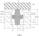
- Fig. 2 is a partially cut part end view showing the gasket 1 and the first member 100 in line II-II in Fig. 1
- Fig. 3 is a partially cut part end view showing the gasket 1 and the first member 100 in III-III line in Fig. 1
- the groove 110 is generally formed in a rectangle, and is defined by a bottom surface 113, and side surfaces 111 and 112 substantially perpendicular to the bottom surface 113. An opposite side of the bottom surface 113 is an opening 110op of the groove 110.
- the gasket 1 is inserted into the groove 110 from the opening 110op. Note that the shape of the groove 110 does not always have to be rectangular.
- the side surfaces 111 and 112 are formed to be gradually away from the bottom surface 113 as progress toward the opening 110op to form the shape of the groove 110 in a trapezoid that gradually enlarges as progresses toward the opening 110op.
- a cylinder head of the vehicle engine as the second member 200 is also shown.
- the second member 200 is overlaid on the first member 100 so as to close the opening 100op of the groove 110.
- the second member 200 is not limited to the above-described cylinder head.
- the gasket 1 is not substantially pressed by the second member 200, that is, is not substantially deformed elastically.
- the gasket 1 includes a body portion 10, a first protrusion pair 20, and one or more second protrusion pairs 30.
- the body portion 10, the first protrusion pair 20, and the one or more second protrusion pairs 30 are integrally molded.
- the gasket 1 is formed so that a section perpendicular to the circumferential direction has a linearly symmetrical shape. Note that the shape of the above-described section of the gasket is not limited to the linearly symmetrical shape.
- the body portion 10 is an annular member extending over the entire circumferential direction of the gasket 1.
- the body portion 10 is formed so that a section perpendicular to the circumferential direction is octagonal.
- the body portion 10 includes a basal surface 11 and a top surface 12 that are parallel to each other and have a same width, a pair of basal surface side inclined surfaces 14 that gradually separate from each other as progress toward the top surface 12 side from the basal surface 11, a pair of top surface side inclined surfaces 16 that gradually separate from each other as progress toward a basal surface 11 side from the top surface 12, and a pair of parallel surfaces 15 that connect the pair of basal surface side inclined surfaces 14 and the pair of top surface side inclined surfaces 16 and are parallel to each other.
- sectional shape of the body portion 10 is not limited to an octagon, but may be, for example, a rectangle, a trapezoid, other quadrilaterals, a hexagon, other polygons, an oval, or an ellipse.
- the basal surface 11 may be formed into a planar shape to be along the bottom surface 113 of the groove 110 and parallel to the bottom surface 113.
- the top surface 12 may be formed into a planar shape to be along a surface 201 on a first member 100 side, of the second member 200, and parallel to the surface 201. Note that the basal surface 11 and the top surface 12 do not necessarily need to have planar shapes, but may have, for example, curved surfaces that protrude as progress toward the bottom surface 113 of the groove 110 and the above-described surface 201 of the second member 200.
- the pair of parallel surfaces 15 are shown in alternate long and short dash lines in Fig. 2 and Fig. 3 .
- the pair of parallel surfaces 15 are perpendicular to the basal surface 11 and the top surface 12, and are parallel to both the side surfaces 111 and 112 in a radial direction of the groove 110.
- the pair of parallel surfaces 15 extend along a depth direction of the groove.
- a distance between the pair of parallel surfaces 15 forms a maximum width of the body portion 10, and the maximum width of the body portion 10 is smaller than a groove width that is a distance between both the side surfaces 111 and 112.
- a pair of parallel surfaces 15 are located in a center in a height direction of the gasket 1.
- a height D1 of the body portion 10 from the basal surface 11 to the top surface 12 is a maximum height of the gasket 1, and is larger than a depth D2 (that is, the depth D2 of the groove 110) of each of the side surface 111 and the side surface 112 of the groove 110.
- the first protrusion pair 20 includes one side first protrusion 21 formed on an outer periphery side of the gasket 1, and another side first protrusion 22 formed on an inner periphery side of the gasket 1.
- the one side first protrusion 21 protrudes from the parallel surface 15 on one side of the body portion 10 toward the side surface 111 of the groove 110.
- the other side first protrusion 22 protrudes from the parallel surface 15 on another side of the body portion 10 toward the side surface 112 of the groove 110.
- Each of the one side first protrusion 21 and the other side first protrusion 22 extends over the entire circumferential direction of the gasket 1. In this way, the first protrusion pair 20 protrude from the body portion 10 toward the outer periphery side and the inner periphery side toward the both the side surfaces 111 and 112 of the groove 110 and extend over the entire circumferential direction.
- each of the one side first protrusion 21 and the other side first protrusion 22 is located on one arbitrary straight line L1 extending in the width direction in a section parallel to the height direction shown in Fig. 2 .
- the one side first protrusion 21 and the other side first protrusion 22 are provided at a same position in the height direction. Note that the positions in the height direction of the one side first protrusion 21 and the other side first protrusion 22 may not be the same.
- At least one of the one side first protrusion 21 and the other side first protrusion 22 may not be located on the straight line L1, and the one side first protrusion 21 may be at such a position higher or lower than the other side first protrusion 22 that it does not overlap the straight line L1, or vice versa.
- the one side first protrusion 21 and the other side first protrusion 22 have substantially same sectional shapes and sectional dimensions.
- the respective sectional shapes along the height directions of the one side first protrusion 21 and the other side first protrusion 22 are substantially rectangular, and fillets are formed at both ends of respective tip ends of the first protrusions 21 and 22.
- the fillets are not essential.
- the gasket 1 of the present embodiment has three second protrusion pairs 30.
- These second protrusion pairs 30 are disposed at approximately regular intervals (that is, intervals of 120°) in the circumferential direction of the gasket 1.
- configurations of the three second protrusion pairs 30 are the same except for positions in the circumferential direction, and therefore, only one of the second protrusion pairs 30 will be described hereinafter.
- the second protrusion pair 30 includes one side second protrusion 31 formed on the outer periphery side of the gasket 1, and another side second protrusion 32 formed on the inner periphery side of the gasket 1.
- the one side second protrusion 31 protrudes from the one side first protrusion 21 of the first protrusion pair 20 toward the side surface 111 of the groove 110.
- the other side second protrusion 32 protrudes from the other side first protrusion 22 of the first protrusion pair 20 toward the side surface 112 of the groove 110.
- the tip ends of the first protrusion pair 20 are shown in broken lines.
- Each of the one side second protrusion 31 and the other side second protrusion 32 are located on one arbitrary straight line L2 extending in a width direction perpendicular to the circumferential direction of the gasket 1 when the gasket 1 is viewed in plan view as in Fig. 1 .
- the one side second protrusion 31 and the other side second protrusion 32 are disposed in a same position in the circumferential direction of the gasket 1. Note that as long as each of the one side second protrusion 31 and the other side second protrusion 32 is located on the straight line L2, the respective positions in the circumferential direction of the one side second protrusion 31 and the other side second protrusion 32 may shift from each other.
- the respective one side second protrusion 31 and other side second protrusion 32 of the second protrusion pair 30 are disposed at the same position in the circumferential direction and protrude toward both the side surfaces 111 and 112 of the groove 110 from the first protrusion pair 20.
- the one side second protrusion 31 and the other side second protrusion 32 have substantially the same sectional shapes and sectional dimensions. Specifically, a shape in plan view of each of the one side second protrusion 31 and the other side second protrusion 32 is substantially semicircular, and a sectional shape along the height direction of each of the one side second protrusion 31 and the other side second protrusion 32 is substantially rectangular. Further, fillets are applied to both ends of tip ends 31f and 32f of the respective second protrusions 31 and 32. However, the fillets are not essential.
- each of the one side second protrusion 31 and the other side second protrusion 32 is located on one arbitrary straight line L3 extending in the width direction in the section parallel to the height direction shown in Fig. 3 .
- the one side second protrusion 31 and the other side second protrusion 32 are provided at the same position in the height direction.
- the positions in the height direction of the one side second protrusion 31 and the other side second protrusion 32 may not be the same.
- At least one of the one side second protrusion 31 and the other side second protrusion 32 may not be located on the straight line L3, and the one side second protrusion 31 may be at such a position higher or lower than the other side second protrusion 32 that it does not overlap the straight line L3, or vice versa.
- a length in the height direction of the second protrusion pair 30 is substantially the same as a length in the height direction of the first protrusion pair 20 and is substantially the same as a length in the height direction of the parallel surface 15 of the body portion 10.
- the length in the height direction of the second protrusion pair 30 may be shorter than the length in the height direction of the first protrusion pair 20.
- a tip end 31f of the one side second protrusion 31 is formed in a planar shape to be along the side surface 111 of the groove 110.
- the tip end 31f may be parallel to the side surface 111, or may incline with respect to the side surface 111 as long as the tip end 31f is in surface contact with the side surface 111 when the gasket 1 is attached into the groove 110.
- a tip end 32f of the other side second protrusion 32 may be formed in a planar shape to be along the side surface 112 of the groove 110.
- the tip end 32f may be parallel to the side surface 112, or may incline with respect to the side surface 112 as long as the tip end 32f is in surface contact with the side surface 112 when the gasket 1 is attached into the groove 110.
- FIG. 4 is a partially cut part end view showing a state before the gasket 1 is attached to the groove 110 of the first member 100, and for convenience of explanation, hatching is omitted.
- a first gasket width W1 from a tip end of the one side first protrusion 21 of the first protrusion pair 20 to a tip end of the other side first protrusion 22 is smaller than a groove width WO of the groove 110.
- a second gasket width W2 from the tip end 31f of the one side second protrusion 31 of the second protrusion pair 30 to the tip end 32f of the other side second protrusion 32 is larger than the groove width WO.
- a length h1 in the height direction of the respective tip ends 31f and 32f of the one side second protrusion 31 and the other side second protrusion 32 of the second protrusion pair 30 is smaller than a width W3 of the basal surface 11, and smaller than a width W4 of the top surface 12.
- the gasket 1 includes the annular body portion 10 having the basal surface 11 to contact the bottom surface 113 of the groove 110 of the first member 100 and the top surface 12 to contact the second member 200 and extending over the entire circumferential direction of the gasket 1, the first protrusion pair 20 respectively protruding from the body portion 10 toward both the side surfaces 111 and 112 of the groove 110 and extending over the entire circumferential direction, and one or more second protrusion pairs 30 respectively protruding from the first protrusion pair 20 toward both the side surfaces 111 and 112 of the groove.
- each of the one side second protrusion 31 and the other side second protrusion 32 of the second protrusion pair 30 is disposed at the same position in the circumferential direction, and the respective tip ends 31f and 32f of the second protrusions 31 and 32 of the second protrusion pair 30 are formed in a planar shape to be along the side surfaces of the groove 110.
- the first gasket width W1 from the tip end of the one side first protrusion 21 of the first protrusion pair 20 to the tip end of the other side first protrusion 22 is smaller than the groove width WO between both the side surfaces 111 and 112 of the groove
- the second gasket width W2 from the tip end 31f of the one side second protrusion 31 of the second protrusion pair 30 to the tip end 32f of the other side second protrusion 32 is larger than the groove width WO.
- the gasket 1 is gripped so that the basal surface 11 of the body portion 10 faces the bottom surface 113 of the groove 110 of the first member 100.
- the gasket 1 is not substantially elastically deformed, and the second gasket width W2 is larger than the groove width WO.
- the gasket 1 is inserted into the groove 110 from the opening 110op of the groove 110.
- the first gasket width W1 is smaller than the groove width WO, it is less susceptible to cause an effect of manufacturing tolerances or the like, and the tip ends of the first protrusion pair 20 are less likely to contact the side surfaces 111 and 112 of the groove 110.
- the first protrusion pair 20 is provided on the entire circumference of the gasket 1, if the tip ends of the first protrusion pair 20 contact the side surfaces 111 and 112, contact areas of the gasket 1 with the side surfaces 111 and 112 become excessively large, and friction can become excessively large. As a result, it becomes difficult to insert the gasket 1 into the groove 110, and attachability is reduced. However, since the tip ends of the first protrusion pair 20 are less likely to contact the side surfaces 111 and 112 of the groove 110 as described above, reduction in attachability is suppressed in advance.
- the first gasket width W1 is smaller than the groove width WO, when the gasket 1 is inserted into the groove 110, there is an air space between the tip ends of the first protrusion pair 20 and the side surfaces 111 and 112 as shown in Fig. 2 . Therefore, in a process of the insertion, air in the groove 110 flows out of the groove. Accordingly, air is prevented from being sealed in the groove 110 by the gasket 1, and attaching of the gasket 1 into the groove 110 is restrained from being hindered by a repulsive force of the sealed air. In this way, according to the gasket 1, attachability can be improved as compared with the conventional one.
- the second protrusion pairs 30 are provided at three spots in the entire circumference of the gasket 1, and the above-described second gasket width W2 is larger than the groove width WO. Therefore, when the gasket 1 is inserted into the groove 110, as shown in Fig. 3 , the respective second protrusion pairs 30 elastically deform and contract, and the tip ends 31f and 32f of the second protrusion pairs 30 contact both the side surfaces 111 and 112 of the groove 110. Thus, the gasket 1 attached to the groove 110 is restrained from falling off the groove 110. In other words, the second protrusion pairs 30 act as fall-off prevention protrusions that restrain fall-off of the gasket 1 from the groove.
- the tip ends 31f and 32f are formed in a planar shape to be along the both the side surfaces 111 and 112, the tip ends 31f and 32f are in surface contact with both the side surfaces 111 and 112. Accordingly, as compared with, for example, the case in which the tip ends 31f and 32f are curved surfaces protruding toward both the side surfaces 111 and 112, the contact areas of the tip ends 31f and 32f and both the side surfaces 111 and 112 increase. Therefore, as compared with the case in which the tip ends 31f and 32f are the curved surfaces protruding toward both the side surfaces 111 and 112, a large frictional force occurs between both the side surfaces 111 and 112, and the gasket 1 can be more restrained from falling off the groove 110.
- the basal surface 11 of the body portion 10 of the gasket 1 contacts the bottom surface 113 of the groove 110.
- the basal surface 11 is formed in a planar shape to be along the bottom surface 113, the basal surface 11 is in surface contact with the bottom surface 113. Accordingly, as compared with the case in which the basal surface 11 is formed to protrude toward the bottom surface 113, for example, a contact area of the basal surface 11 and the bottom surface 113 increases. Therefore, the gasket 1 can be restrained from inclining in the groove 110.
- the surface 201 of the second member 200 is brought into contact with the top surface 12 of the gasket 1 attached to the groove 110.
- the second member 200 is overlaid while being pressed toward the first member 100, the gasket 1 is compressed by the first member 100 and the second member 200.
- the gasket 1 closely contacts each of the bottom surface 113 of the first member 100 and the surface 201 of the second member 200 by a repulsive force to the compression, and the gap between the first member 100 and the second member 200 is sealed.
- the basal surface 11 is formed in a planar shape to be along the bottom surface 113 as described above, the contact area of the basal surface 11 and the bottom surface 113 increases. Therefore, when the second member 200 is overlaid, stress can be restrained from being locally concentrated in a vicinity of the basal surface 11.
- the top surface 12 is formed in a planar shape to be along the surface 201 of the second member 200 as described above, the top surface 12 and the surface 201 are in surface contact with each other. Therefore, as compared with the case in which the top surface 12 is the curved surface that protrudes toward the surface 201 of the second member 200, for example, a contact area of the top surface 12 and the surface 201 increases. Therefore, when the second member 200 is overlaid, stress can be restrained from being locally concentrated in a vicinity of the top surface 12.
- the first protrusion pair 20 protrudes toward both the side surfaces 111 and 112 of the groove 110 from the body portion 10. According to the configuration like this, even if the gasket 1 starts to incline to either side of the side surfaces 111 and 112 when the second member 200 is overlaid, the first protrusion pair 20 abuts on the side surfaces of the groove 110 before the body portion 10 abuts on the side surfaces of the groove. Therefore, the gasket 1 can be restrained from inclining in a process of overlaying the second member 200. Thus, the first protrusion pair 20 acts as the fall-off prevention protrusions that restrain fall of the gasket 1.
- the gasket 1 since the first protrusion pair 20 protrudes toward both the side surfaces 111 and 112 of the groove from the body portion 10, the gasket 1 becomes thick and rigidity of the gasket 1 increases. Therefore, the gasket 1 can be restrained from bending in the process of overlaying the second member 200.
- the first protrusion pair 20 is continuously formed over the entire circumferential direction, it is avoided that the shape of the gasket is complicated as compared with the case in which the first protrusion pair is intermittently formed in the circumferential direction.
- each of the one side second protrusion 31 and the other side second protrusion 32 is provided at the same position in the height direction of the gasket 1. According to the configuration like this, meandering deformation of the gasket 1 along the height direction in the groove 110 can be restrained, as compared with the case in which the positions in the height direction of the one side second protrusion 31 and the other side second protrusion 32 are not the same.
- the example is descried, in which the respective lengths h1 in the height direction of the tip ends 31f and 32f of the one side second protrusion 31 and the other side second protrusion 32 of the second protrusion pair 30 are smaller than the width W3 of the basal surface 11, and smaller than the width W4 of the top surface 12.
- the length h1 in the height direction may be equal to or larger than the width W3 of the basal surface 11, and may be equal to or larger than the width W4 of the top surface 12.
- the contact surface with the side surface 111 and the side surface 112 of the groove 110 increases. Therefore, fall-off of the gasket 1 from the groove 110 can be restrained more effectively.
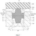
- Fig. 7 is a sectional view showing a state in which a gasket according to the present embodiment is attached to a groove of a first member similarly to Fig. 3 .
- Fig 7 is a view showing a section perpendicular to a circumferential direction to a gasket 1000 (section parallel to a height direction).
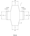
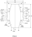
- Fig. 8 is a cut part end view showing a body portion and a first protrusion pair of the gasket according to the present embodiment. Note that in Fig. 8 , hatching is omitted for convenience.
- the gasket 1000 according to the present embodiment has a configuration similar to the gasket 1 of the first embodiment except for a configuration of the first protrusion pair. Accordingly, for the gasket 1000, only the point relating to a first protrusion pair 1020 is described, and the other components are assigned with similar reference signs to those in the first embodiment and explanation thereof is omitted.
- the gasket 1000 is formed so that the section perpendicular to the circumferential direction (section parallel to the height direction) is linearly symmetrical.
- the first protrusion pair 1020 of the gasket 1000 is located in a substantially center in the height direction of the gasket 1000.
- the first protrusion pair 1020 has one side first protrusion 1021 located on a side surface 111 side of a groove 110 of a first member 100 with respect to a body portion 10, and another side first protrusion 1022 located on a side surface 112 side of the groove 110.
- the one side first protrusion 1021 and the other side first protrusion 1022 are formed to be linearly symmetrical with respect to a line L4 extending in the height direction in a center of the body portion 10 in a width direction. Further, the one side first protrusion 1021 and the other side first protrusion 1022 are both located on one arbitrary straight line L3 extending in the width direction. In the present embodiment, the straight line L3 is defined as a line passing through a center of each of the one side first protrusion 1021 and the other side first protrusion 1022 in the height direction. Each of the one side first protrusion 1021 and the other side first protrusion 1022 is formed to be linearly symmetrical with respect to the straight line L3.
- the one side first protrusion 1021 is formed in a substantially rectangle in sectional view perpendicular to the circumferential direction.
- the one side first protrusion 1021 includes a pair of side surfaces 1021S extending perpendicularly to a parallel surface 15 (that is, parallel to the width direction) toward the side surface 111 side of the groove 110 from the parallel surface 15 on one side of the body portion 10, and a tip end (tip end surface) 1021f extending perpendicularly to the pair of side surfaces 1021S (that is, parallel to the height direction).
- One of the pair of side surfaces 1021S connects an end portion on a second member 200 side, of the tip end 1021f, and an end portion on the second member 200 side of the parallel surface 15 of the body portion 10. Further, another one of the pair of side surfaces 1021S connects an end portion on a bottom surface 113 side of the groove 110 in the tip end 1021f, and an end portion on the bottom surface 113 side in the parallel surface 15 of the body portion 10.
- connecting portions between the pair of side surfaces 1021S and the body portion 10 are fillets Rf that are rounded. However, rounding the connecting portions like this is not essential.
- connecting portions between a top surface 12 and a pair of top surface side inclined surfaces 16 in the body portion 10, and connecting portions between a basal surface 11 and a pair of basal surface side inclined surfaces 14 in the body portion 10 are also fillets Rf.
- rounding the connecting portions like this is not essential.
- the connecting portions between the top surface 12 and the pair of top surface side inclined surfaces 16 in the body portion 10, and the connecting portions between the basal surface 11 and the pair of basal surface side inclined surfaces 14 in the body portion 10 may be rounded.
- a recessed part 1120 recessed to the body portion 10 side is formed in a substantially center in the height direction of the tip end 1021f.
- the recessed part 1120 is formed linearly symmetrical with respect to the straight line L3, and is a space defined by a curved surface 1122 located on the second member 200 side with respect to the straight line L3, a curved surface 1123 located on the bottom surface 113 side of the groove 110 with respect to the straight line L3, and a bottom surface 1121 connecting respective end portions on the body portion 10 side of the curved surface 1122 and the curved surface 1123.
- the bottom surface 1121 extends parallel to the height direction.
- a pair of protrusions 1021P protruding closer to the side surface 111 than the bottom surface 1121 are formed respectively on the second member 200 side and the bottom surface 113 side of the groove 110 with the bottom surface 1121 as a reference.
- the other side first protrusion 1022 is formed in a substantially rectangle in sectional view perpendicular to the circumferential direction.
- the other side first protrusion 1022 includes a pair of side surfaces 1022S extending perpendicularly to a parallel surface 15 toward a side surface 112 side of the groove 110 from the parallel surface 15 on the other side of the body portion 10, and a tip end (tip end surface) 1022f extending perpendicularly to the pair of side surfaces 1022S (that is, parallel to the height direction).
- One of the pair of side surfaces 1022S connects an end portion on the second member 200 side, of the tip end 1022f, and an end portion on the second member 200 side of the parallel surface 15 of the body portion 10.
- another one of the pair of side surfaces 1022S connects an end portion on the bottom surface 113 side of the groove 110 in the tip end 1022f, and an end portion on the bottom surface 113 side in the parallel surface 15 of the body portion 10.
- connecting portions between the pair of side surfaces 1022S and the body portion 10 are fillets Rf that are rounded.
- the connecting portions between the pair of side surfaces 1021S and the body portion 10 and the connecting portions between the pair of side surfaces 1022S and the body portion 10 is not essential.
- the connecting portions between the first protrusion pair 20 and the body portion 10 may be rounded.
- a recessed part 1220 recessed to the body portion 10 side is formed in a center in the height direction of the tip end 1022f.
- the recessed part 1220 is formed linearly symmetrical with respect to the straight line L3, and is a space defined by a curved surface 1222 located on the second member 200 side with respect to the straight line L3, a curved surface 1223 located on the bottom surface 113 side of the groove 110 with respect to the straight line L3, and a bottom surface 1221 connecting respective end portions on the body portion 10 side of the curved surface 1222 and the curved surface 1223.
- the bottom surface 1221 extends parallel to the height direction.
- a pair of protrusions 1022P protruding the side surface 112 side from the bottom surface 1221 are formed respectively on the second member 200 side and the bottom surface 113 side with the bottom surface 1221 as a reference.
- the recessed part 1220 is linearly symmetrical with the recessed part 1120 with the line L4 extending in the height direction in the center of the body portion 10 in the width direction as a reference.
- it is not essential that the recessed part 1220 is symmetrical with the recessed part 1120.
- gaps G are formed respectively between the tip end 1021f of the one side first protrusion 1021 and the side surface 111 of the groove 110, and between the tip end 1022f of the other side first protrusion 1022 and the side surface 112 of the groove 110.
- a total "G + G" of the respective gaps G (total of lengths in the width direction of the respective gaps G) can be represented by formula (1) below using a groove width w0, and a first gasket width w1 from the tip end 1021f of the one side first protrusion 1021 to the tip end 1022f of the other side first protrusion 1022.
- G + G w0 ⁇ w1
- the total "G + G" of the respective gaps G is not particularly limited, but is equal to or less than 1.0 mm in the present embodiment.
- a length in the width direction of the gap G between the tip end 1021f of the one side first protrusion 1021 and the side surface 111 of the groove 110, and a length in the width direction of the gap G between the tip end 1022f of the other side first protrusion 1022 and the side surface 112 of the groove 110 may be the same or different.
- a total of gaps between the tip end of the one side first protrusion 21 and the side surface 111 of the groove 110, and between the tip end of the other side first protrusion 22 and the side surface 112 of the groove 110 may be similarly equal to or less than 1.0 mm.
- a ratio h2/h0 of the height h2 of the first protrusion pair 20 to the height h0 of the body portion 10 is not particularly limited, but in the present embodiment, is 0.25 ⁇ h2 / h0 ⁇ 0.5 .
- the height h2 is also a height of the parallel surface 15 of the body portion 10.
- the height h2 of the first protrusion pair 20 is longer than each of the width w3 (see Fig. 3 ) of the basal surface 11 of the body portion 10 and the width w4 (see Fig. 3 ) of the top surface 12.
- the height h2 may be the same as the width w3 and the width w4 or shorter than the width w3 and the width w4.
- the height h2 is longer than the width w3 and the width w4 it is easy to form the recessed part 1120 and the recessed part 1220.
- each of recesses ⁇ of the recessed part 1120 and the recessed part 1220 can be represented by formula (2) below by using the width w5 and the first gasket width w1.
- the recess ⁇ is a distance from a most recessed portion (bottom surface 1121) of the recessed part 1120 to the tip end 1021f of the one side first protrusion 1021, and is a distance from a most recessed portion (bottom surface 1221) of the recessed part 1220 to the tip end 1022f of the other side first protrusion 1022, in the width direction of the gasket 1000.
- a dimension of the recess ⁇ is not particularly limited, but is equal to or less than 0.5 mm in the present embodiment.
- the gasket 1000 When the gasket 1000 is positioned in the groove 110, and the gasket 1000 is pressed in the height direction by the second member 200, the gasket 1000 deforms in the width direction and is collapsed, the tip end 1021f of the first protrusion pair 1020 presses the side surface 111 of the groove 110, and the tip end 1022f of the first protrusion pair 1020 presses the side surface 112 of the groove 110. With this, the gasket 1000 receives reaction forces from the side surfaces 111 and 112.
- recessed parts such as the recessed parts 1120 and 1220 are not formed at the first protrusion pair 20, and therefore, when the flat tip ends of the first protrusion pair 20 contact the side surfaces 111 and 112 of the groove 110 by being pressed by the second member 200, the flat tip ends of the first protrusion pair 20 are only compressed in the width direction with respect to the reaction forces of the side surfaces 111 and 112, so that compression stress and the reaction forces of the side surfaces 111 and 112 tend to be large (see Fig. 5 ). That is to say, the gasket 1 of the first embodiment is strongly pressed in the height direction by the second member 200, and in the width direction by the side surfaces 111 and 112, respectively.
- the gasket 1 may incline in the groove 110 to escape from strong forces from the height direction and the width direction.
- the protrusions 1021P and 1022P that are formed as the recessed parts 1120 and 1220 are formed are present at the tip ends 1021f and 1022f of the first protrusion pair 1020. Therefore, when the tip ends 1021f and 1022f of the first protrusion pair 1020 press the side surfaces 111 and 112 with pressing from the second member 200, the protrusions 1021P and 1022P deform, and the pressing force which the first protrusion pair 1020 exerts on the side surfaces 111 and 112 is reduced.
- reaction forces acting on the gasket 1000 from the side surfaces 111 and 112 are reduced.
- a force acting on the gasket is reduced when it is pressed by the second member 200, and therefore the gasket can be more restrained from inclining in the groove 110 when pressed by the second member 200 as compared with the gasket 1 of the first embodiment.
- the reaction forces acting on the gasket 1000 from the side surfaces 111 and 112 of the groove 110 are reduced, the reaction force which the gasket 1000 exerts on the second member 200 can be reduced.
- the gasket 1000 has a substantially similar configuration to the gasket 1 of the first embodiment, except for the configuration of the first protrusion pair 1020 as described above. Therefore, according to the gasket 1000, it is possible to obtain similar effects to the effects obtained by the aforementioned gasket 1, except that the gasket is more restrained from inclining in the groove 110 when pressed by the second member 200 as compared with the gasket 1 of the first embodiment.
- the first protrusion pair 1020 in the first protrusion pair 1020, there are a first pair of protrusion portions composed of the protrusion 1021P on the second member 200 side of the one side first protrusion 1021, and the protrusion 1022P on the second member 200 side of the other side first protrusion 1022, and a second pair of protrusion portions composed of the protrusion 1021P on the bottom surface 113 side of the one side first protrusion 1021 and the protrusion 1022P on the bottom surface 113 side of the other side first protrusion 1022, and since the first pair and the second pair are connected in the height direction, when a mold is to be removed in the height direction at the time of molding of the gasket 1000, one of the first pair and the second pair causes unreasonable removal.
- the distance from the most recessed portion of the recessed part to the tip end of the first protrusion pair is suppressed to 0.5 mm or less, in the width direction of the gasket. According to the configuration like this, even if unreasonable removal is caused as described above, loss of moldability can be effectively restrained, because the length by which the first pair and the second pair protrude is short.
- the total "G + G" of the respective gaps G is equal to or less than 1.0 mm.
- each of a space between the tip end 1021f of the one side first protrusion 1021 and the side surface 111 of the groove 110, and a space between the tip end 1022f of the other side first protrusion 1022 and the side surface 112 of the groove 110 is relatively narrow, and therefore it is possible to enhance an effect of preventing the gasket from falling down by the first protrusion pair 1020.
- the first protrusion pair 1020 can be prevented from non-contacting the side surfaces 111 and 112 of the groove 110 when the gasket 1000 is pressed in the height direction by the second member 200.
- the first protrusion pair 1020 can more reliably press the side surfaces 111 and 112 of the groove 110 when the gasket 1000 is pressed by the second member 200, and therefore, it is possible to bring the gasket 1000 and the first member 100 into close contact with each other in the width direction more reliably.
- the ratio h2/h0 of the height h2 of the first protrusion pair 20 to the height h0 of the body portion 10 is 0.25 ⁇ h2 / h0 ⁇ 0.5 . If 0.25 ⁇ h2/h0 is satisfied, a contact surface area between the tip end 1021f of the first protrusion pair 1020 and the side surface 111 of the groove 110, or a contact area between the tip end 1022f of the first protrusion pair 1020 and the side surface 112 of the groove 110 is ensured to be large to some extent when the gasket 1000 is to incline in the groove 110, and therefore, it is possible to prevent the gasket 1000 from falling down in the groove 110 more effectively.
- a sectional area (see Fig. 2 , Fig. 3 , and Fig. 7 ) of the gasket perpendicular to the circumferential direction to a sectional area of the groove 110 perpendicular to the circumferential direction is defined as a filling factor for convenience. If h2/h0 ⁇ 0.5 is satisfied, the above-described filling factor is restrained from exceeding 100%, as a result of which, when the gasket 1000 is pressed in the height direction by the second member 200, the gasket 1000 is restrained from being excessively compressed to cause cracking, or the repulsive force of the gasket 1000 is restrained from excessively increasing.
- the present embodiment is not limited to the above-described example.
- the recessed parts are formed in both the one side first protrusion 1021 and the other side first protrusion 1022, but the recessed part may be formed in only one of the one side first protrusion 1021 and the other side first protrusion 1022.
- bottom surfaces 1121 and 1221 defining the recessed parts 1120 and 1220 are planes parallel to the height direction
- the bottom surfaces 1121 and 1221 are not limited to this.
- bottom surfaces 1121 and 1221 may be surfaces that sink toward a body portion 10 side from both end portions in a height direction of recessed parts 1120 and 1220 to center portions. That is, in this example, the bottom surfaces 1121 and 1221 are convex toward the body portion 10 side, and are not planes parallel to the height direction.
- the example is described, in which the pair of side surfaces 1021S of the one side first protrusion 1021 and the pair of side surfaces 1022S of the other side first protrusion 1022 extend perpendicularly to the parallel surfaces 15 of the body portion 10.
- at least one of the pair of side surfaces 1021S and the pair of side surfaces 1022S may not extend parallel to the parallel surfaces 15.
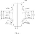
- a modification as shown in Fig 10 may be configured.
- a pair of side surfaces 1021S of one side first protrusion 1021 separate from each other as progress toward a body portion 10 from a tip end 1021f of the one side first protrusion 1021 in a width direction and connect to a parallel surface 15 of the body portion 10 via fillets Rf.
- the one side first protrusion 1021 is formed into a tapered shape that enlarges as progresses toward the body portion 10 in sectional view perpendicular to a circumferential direction of a gasket 1000.
- a height of a connecting portion of the pair of side surfaces 1021S of the one side first protrusion 1021 and the body portion 10, that is, a height h2 of the parallel surface 15 is larger than a height h3 of a tip end 1021f of the one side first protrusion 1021.
- another side first protrusion 1022 is formed to be linearly symmetrical with the one side first protrusion 1021 with respect to a line L4 extending in the height direction in a center of the body portion 10 in the width direction.
- the other side first protrusion 1022 is formed in a tapered shape that enlarges as progresses toward the body portion 10 in sectional view perpendicular to the circumferential direction of the gasket 1000. Further, a height of a connecting portion between a pair of side surfaces 1022S of the other side first protrusion 1022 and the body portion 10, that is, the height h2 of the parallel surface 15 is larger than a height h3 of a tip end 1022f of the other side first protrusion 1022. According to the modification in Fig.
- a root (connecting portion with the body portion 10) of each of the one side first protrusion 1021 and the other side first protrusion 1022 is wider than the tip end, and therefore, strength of the above-described root increases. Therefore, when the gasket in the groove 110 is pressed by the second member 200, an effect of surface pressure acting on the gasket from the side surface 111 and the side surface 112 of the groove 110 is reduced.
- the modification in Fig. 10 the example in which both the one side first protrusion 1021 and the other side first protrusion 1022 are formed in the tapered shape is described, but only one of the one side first protrusion 1021 and the other side first protrusion 1022 may be formed in the tapered shape. Further, the modification in Fig. 10 (that is, a mode in which at least one of the one side first protrusion and the other side first protrusion is formed in the tapered shape as described above) may be applied to the gasket 1 of the first embodiment.
- the one side first protrusion 21 and the other side first protrusion 22 may have sectional shapes and sectional dimensions that are different from each other.
- the above-described sectional shapes are not limited to rectangles.
- the sectional shapes may be trapezoids, parallelograms, or polygons equal to or larger than pentagons, or may be shapes based on curved surfaces such as semi-elliptical shapes.
- the one side second protrusion 31 and the other side second protrusion 32 may have sectional shapes and sectional dimensions that are different from each other.
- the shapes in plan view of the one side second protrusion 31 and the other side second protrusion 32 are not limited to semicircular shapes, but may be rectangles, for example.
- sectional shapes thereof along the height direction are not limited to rectangles, but may be, for example, trapezoids, parallelograms, and polygons equal to or larger than pentagons, or may cured surface shapes except for the tip ends.
- the example in which the three second protrusion pairs 30 are disposed at regular intervals in the circumferential direction of the gasket 1 is described.
- one or more second protrusion pairs 30 can be provided, and two, four, five or more second protrusion pairs 30 may be provided at regular intervals along the circumferential direction.
- these protrusion pairs 30 may not be disposed at regular intervals.
Landscapes
- Engineering & Computer Science (AREA)
- General Engineering & Computer Science (AREA)
- Mechanical Engineering (AREA)
- Physics & Mathematics (AREA)
- Geometry (AREA)
- Gasket Seals (AREA)
Abstract
Description
- The present invention relates to a gasket.
- Conventionally, as a gasket, for example, a gasket described in
Patent Literature 1 as follows has been known. The gasket described inPatent Literature 1 is annularly formed so as to seal a gap between a first member in which an annular groove is formed, and a second member to be overlaid on the first member so as to close an opening of the groove of the first member. The gasket includes a first portion extending from an end surface on one side to contact a bottom surface of the groove to an end surface on another side to contact the second member, and a second portion that protrudes toward both side surfaces of the groove from the first portion. The first portion and the second portion extend over a circumferential direction of the gasket. In the gasket described inPatent Literature 1, a width of the gasket in the second portion is the same as a groove width of the groove. - Patent Literature 1:
Japanese Patent Application Publication No. 2018-096400 - According to the gasket of
Patent Literature 1, the width of the gasket in the second portion is the same as the groove width, and therefore, when the gasket is attached into the groove, the second portion contacts both the side surfaces of the groove. Accordingly, it is possible to restrain the gasket from falling off the groove. However, on the other hand, air in the groove is sealed by the gasket as a result of the second portion contacting both the side surfaces of the groove over the entire circumference. As a result, insertion of the gasket into the groove tends to be hindered by the repulsive force of the sealed air. Accordingly, there has been a desire to further improve attachability of the gasket to the groove in the gasket ofPatent Literature 1. - The present invention is made in view of the point as above, and it is an object of the present invention to provide a gasket that is less likely to fall off the groove, and can improve attachability.
- In order to attain the above-described object, the present invention is a gasket in an annular shape to seal a gap between a first member in which an annular groove is formed and a second member to be overlaid on the first member to close an opening of the groove, characterized by including a body portion in an annular shape having a basal surface to contact a bottom surface of the groove and a top surface to contact the second member, and extending over an entire circumferential direction of the gasket, a first protrusion pair protruding from the body portion respectively toward both side surfaces in a radial direction of the groove and extending over the entire circumferential direction, and one or more second protrusion pairs protruding from the first protrusion pair respectively toward both the side surfaces of the groove, and characterized in that respective protrusions of the second protrusion pair are disposed at a same position in the circumferential direction, tip ends of the respective protrusions are formed in a planar shape to be along the side surfaces of the groove, a first gasket width from a tip end of one protrusion of the first protrusion pair to a tip end of another protrusion is smaller than a groove width between both the side surfaces of the groove, and a second gasket width from a tip end of one protrusion of the second protrusion pair to a tip end of another protrusion is larger than the groove width.
- Further, it is preferable that the respective protrusions of the second protrusion pair are provided at a same position in a height direction of the gasket.
- Further, the basal surface of the body portion may be formed in a planar shape to be along the bottom surface of the groove, and a length of the tip end of at least one protrusion of the second protrusion pair in a height direction of the gasket may be equal to or larger than a width of the basal surface.
- Further, the top surface of the body portion may be formed in a planar shape to be along a surface of the second member that is to abut on the top surface, and a length of the tip end of at least one protrusion of the second protrusion pair in a height direction of the gasket may be equal to or larger than a width of the top surface.
- Further, a recessed part recessed to a body portion side may be formed at the tip end of at least one protrusion of the first protrusion pair. In this case, in the width direction of the gasket, a distance from a most recessed portion of the recessed part to the tip end may be equal to or less than 0.5 mm.
- Further, in sectional view perpendicular to the circumferential direction of the gasket, at least one protrusion of the first protrusion pair may be formed in a tapered shape that enlarges as progresses toward the body portion.
- According to the configuration as above, it is possible to provide the gasket that is less likely to fall from the groove, and can improve attachability.
-
- [
Fig. 1] Fig. 1 is a plan view showing a state in which a gasket according to a first embodiment of the present invention is attached to a groove of a first member. - [
Fig. 2] Fig. 2 is a partially cut part end view in line II-II showing the gasket and the first member shown inFig. 1 with a second member. - [
Fig. 3] Fig. 3 is a partially cut part end view in III-III line showing the gasket and the first member shown inFig 1 with the second member. - [
Fig. 4] Fig. 4 is a partially cut part end view showing a state before the gasket shown inFig 1 is attached to the groove of the first member. - [
Fig. 5] Fig. 5 is a partially cut part end view in line II-II showing a state in which the second member is overlaid on the first member in which the gasket shown inFig. 1 is attached to the groove. - [
Fig. 6] Fig. 6 is a sectional view showing a modification of the gasket according to the first embodiment, which is a sectional view showing a view before the gasket is attached to the groove. - [
Fig. 7] Fig. 7 is a sectional view showing a state in which a gasket according to a second embodiment of the present invention is attached to a groove of a first member, similarly toFig. 3 . - [
Fig. 8] Fig. 8 is a cut part end view showing a body portion and a first protrusion pair of the gasket shown inFig. 7 . - [
Fig. 9] Fig. 9 is a cut part end view showing a first modification of the gasket shown inFig. 7 , similarly toFig. 8 . - [
Fig. 10] Fig. 10 is a cut part end view showing a second modification of the gasket shown inFig. 7 , similarly toFig. 8 . - Hereinafter, modes for carrying out a gasket according to the present invention will be illustrated with the accompanying drawings. Embodiments illustrated below are for ease of understanding of the present invention and are not intended to be interpreted as limiting the present invention. The present invention can be modified and improved from the following embodiments without departing from the gist of the present invention. Further, in the accompanying drawings, dimensions of each member may be shown by being exaggerated for ease of understanding.
- A gasket according to the present embodiment is an annular gasket to seal a gap between a first member in which an annular groove is formed, and a second member to be overlaid on the first member so as to close an opening of the groove.
-
Fig. 1 is a plan view showing the gasket to be attached to a head cover of a vehicle engine. Note that inFig. 1 , in order to prevent agasket 1 from being unclear, the head over as afirst member 100 is shown in a broken line. As shown inFig. 1 , agroove 110 is annularly formed in thefirst member 100. Note that thefirst member 100 is not limited to the above-described head cover. Thegasket 1 is annularly formed so as to be attachable to an entire circumference of thegroove 110, and is formed of, for example, a rubber material such as a silicon rubber or a fluorine rubber so as to be elastically deformable. Note that inFig. 1 , thegasket 1 and thegroove 110 are expressed as circular, but thegasket 1 and thegroove 110 can have annular shapes, and may have, for example, an ellipse, oval, rectangle, square, oblong, trapezoid, other quadrilaterals, polygon, and the like. -
Fig. 2 is a partially cut part end view showing thegasket 1 and thefirst member 100 in line II-II inFig. 1 , andFig. 3 is a partially cut part end view showing thegasket 1 and thefirst member 100 in III-III line inFig. 1 . As shown inFig. 2 andFig. 3 , thegroove 110 is generally formed in a rectangle, and is defined by abottom surface 113, andside surfaces bottom surface 113. An opposite side of thebottom surface 113 is an opening 110op of thegroove 110. Thegasket 1 is inserted into thegroove 110 from the opening 110op. Note that the shape of thegroove 110 does not always have to be rectangular. For example, theside surfaces bottom surface 113 as progress toward the opening 110op to form the shape of thegroove 110 in a trapezoid that gradually enlarges as progresses toward the opening 110op. - In
Fig. 2 andFig. 3 , a cylinder head of the vehicle engine as thesecond member 200 is also shown. Thesecond member 200 is overlaid on thefirst member 100 so as to close the opening 100op of thegroove 110. Note that thesecond member 200 is not limited to the above-described cylinder head. Further, in the states shown inFig. 2 andFig. 3 , thegasket 1 is not substantially pressed by thesecond member 200, that is, is not substantially deformed elastically. - As shown in
Fig 1 to Fig 3 , thegasket 1 includes abody portion 10, afirst protrusion pair 20, and one or more second protrusion pairs 30. Thebody portion 10, the first protrusion pair 20, and the one or moresecond protrusion pairs 30 are integrally molded. Further, in the present embodiment, as shown inFig. 2 andFig 3 , thegasket 1 is formed so that a section perpendicular to the circumferential direction has a linearly symmetrical shape. Note that the shape of the above-described section of the gasket is not limited to the linearly symmetrical shape. - The
body portion 10 is an annular member extending over the entire circumferential direction of thegasket 1. In the present embodiment, thebody portion 10 is formed so that a section perpendicular to the circumferential direction is octagonal. Specifically, thebody portion 10 includes abasal surface 11 and atop surface 12 that are parallel to each other and have a same width, a pair of basal surface side inclined surfaces 14 that gradually separate from each other as progress toward thetop surface 12 side from thebasal surface 11, a pair of top surface side inclined surfaces 16 that gradually separate from each other as progress toward abasal surface 11 side from thetop surface 12, and a pair ofparallel surfaces 15 that connect the pair of basal surface side inclined surfaces 14 and the pair of top surface side inclined surfaces 16 and are parallel to each other. Note that the sectional shape of thebody portion 10 is not limited to an octagon, but may be, for example, a rectangle, a trapezoid, other quadrilaterals, a hexagon, other polygons, an oval, or an ellipse. - In the present embodiment, the
basal surface 11 may be formed into a planar shape to be along thebottom surface 113 of thegroove 110 and parallel to thebottom surface 113. Further, thetop surface 12 may be formed into a planar shape to be along asurface 201 on afirst member 100 side, of thesecond member 200, and parallel to thesurface 201. Note that thebasal surface 11 and thetop surface 12 do not necessarily need to have planar shapes, but may have, for example, curved surfaces that protrude as progress toward thebottom surface 113 of thegroove 110 and the above-describedsurface 201 of thesecond member 200. - The pair of
parallel surfaces 15 are shown in alternate long and short dash lines inFig. 2 andFig. 3 . The pair ofparallel surfaces 15 are perpendicular to thebasal surface 11 and thetop surface 12, and are parallel to both the side surfaces 111 and 112 in a radial direction of thegroove 110. The pair ofparallel surfaces 15 extend along a depth direction of the groove. A distance between the pair ofparallel surfaces 15 forms a maximum width of thebody portion 10, and the maximum width of thebody portion 10 is smaller than a groove width that is a distance between both the side surfaces 111 and 112. A pair ofparallel surfaces 15 are located in a center in a height direction of thegasket 1. - When the
gasket 1 is not substantially deformed elastically, a height D1 of thebody portion 10 from thebasal surface 11 to thetop surface 12 is a maximum height of thegasket 1, and is larger than a depth D2 (that is, the depth D2 of the groove 110) of each of theside surface 111 and theside surface 112 of thegroove 110. - As shown in
Fig. 1 andFig. 2 , thefirst protrusion pair 20 includes one sidefirst protrusion 21 formed on an outer periphery side of thegasket 1, and another sidefirst protrusion 22 formed on an inner periphery side of thegasket 1. The one sidefirst protrusion 21 protrudes from theparallel surface 15 on one side of thebody portion 10 toward theside surface 111 of thegroove 110. The other sidefirst protrusion 22 protrudes from theparallel surface 15 on another side of thebody portion 10 toward theside surface 112 of thegroove 110. Each of the one sidefirst protrusion 21 and the other sidefirst protrusion 22 extends over the entire circumferential direction of thegasket 1. In this way, thefirst protrusion pair 20 protrude from thebody portion 10 toward the outer periphery side and the inner periphery side toward the both the side surfaces 111 and 112 of thegroove 110 and extend over the entire circumferential direction. - In the present embodiment, each of the one side
first protrusion 21 and the other sidefirst protrusion 22 is located on one arbitrary straight line L1 extending in the width direction in a section parallel to the height direction shown inFig. 2 . In other words, the one sidefirst protrusion 21 and the other sidefirst protrusion 22 are provided at a same position in the height direction. Note that the positions in the height direction of the one sidefirst protrusion 21 and the other sidefirst protrusion 22 may not be the same. In other words, at least one of the one sidefirst protrusion 21 and the other sidefirst protrusion 22 may not be located on the straight line L1, and the one sidefirst protrusion 21 may be at such a position higher or lower than the other sidefirst protrusion 22 that it does not overlap the straight line L1, or vice versa. - In the present embodiment, the one side
first protrusion 21 and the other sidefirst protrusion 22 have substantially same sectional shapes and sectional dimensions. Specifically, the respective sectional shapes along the height directions of the one sidefirst protrusion 21 and the other sidefirst protrusion 22 are substantially rectangular, and fillets are formed at both ends of respective tip ends of thefirst protrusions - As shown in
Fig. 1 andFig. 3 , thegasket 1 of the present embodiment has three second protrusion pairs 30. These second protrusion pairs 30 are disposed at approximately regular intervals (that is, intervals of 120°) in the circumferential direction of thegasket 1. In the present embodiment, configurations of the three second protrusion pairs 30 are the same except for positions in the circumferential direction, and therefore, only one of the second protrusion pairs 30 will be described hereinafter. - As shown in
Fig. 3 , thesecond protrusion pair 30 includes one sidesecond protrusion 31 formed on the outer periphery side of thegasket 1, and another sidesecond protrusion 32 formed on the inner periphery side of thegasket 1. The one sidesecond protrusion 31 protrudes from the one sidefirst protrusion 21 of thefirst protrusion pair 20 toward theside surface 111 of thegroove 110. The other sidesecond protrusion 32 protrudes from the other sidefirst protrusion 22 of thefirst protrusion pair 20 toward theside surface 112 of thegroove 110. Note that inFig. 3 , in order to show a positional relationship of thefirst protrusion pair 20 and thesecond protrusion pair 30, the tip ends of thefirst protrusion pair 20 are shown in broken lines. - Each of the one side
second protrusion 31 and the other sidesecond protrusion 32 are located on one arbitrary straight line L2 extending in a width direction perpendicular to the circumferential direction of thegasket 1 when thegasket 1 is viewed in plan view as inFig. 1 . In other words, the one sidesecond protrusion 31 and the other sidesecond protrusion 32 are disposed in a same position in the circumferential direction of thegasket 1. Note that as long as each of the one sidesecond protrusion 31 and the other sidesecond protrusion 32 is located on the straight line L2, the respective positions in the circumferential direction of the one sidesecond protrusion 31 and the other sidesecond protrusion 32 may shift from each other. In this way, the respective one sidesecond protrusion 31 and other sidesecond protrusion 32 of thesecond protrusion pair 30 are disposed at the same position in the circumferential direction and protrude toward both the side surfaces 111 and 112 of thegroove 110 from thefirst protrusion pair 20. - Note that when attention is paid to a site where the
second protrusion pair 30 is provided, of thegasket 1, in the section parallel to the height direction (seeFig. 3 ), only onesecond protrusion pair 30 is provided in the site. According to the configuration like this, it is avoided that the shape of thegasket 1 becomes complicated. Further, even when a mold is opened in the height direction when thegasket 1 is molded, only onesecond protrusion pair 30 is present in the height direction, so that interference of the protrusion can be avoided, and unreasonable removal can be avoided. - In the present embodiment, the one side
second protrusion 31 and the other sidesecond protrusion 32 have substantially the same sectional shapes and sectional dimensions. Specifically, a shape in plan view of each of the one sidesecond protrusion 31 and the other sidesecond protrusion 32 is substantially semicircular, and a sectional shape along the height direction of each of the one sidesecond protrusion 31 and the other sidesecond protrusion 32 is substantially rectangular. Further, fillets are applied to both ends of tip ends 31f and 32f of the respectivesecond protrusions second protrusion 31 and the other sidesecond protrusion 32 is located on one arbitrary straight line L3 extending in the width direction in the section parallel to the height direction shown inFig. 3 . In other words, the one sidesecond protrusion 31 and the other sidesecond protrusion 32 are provided at the same position in the height direction. However, the positions in the height direction of the one sidesecond protrusion 31 and the other sidesecond protrusion 32 may not be the same. In other words, at least one of the one sidesecond protrusion 31 and the other sidesecond protrusion 32 may not be located on the straight line L3, and the one sidesecond protrusion 31 may be at such a position higher or lower than the other sidesecond protrusion 32 that it does not overlap the straight line L3, or vice versa. - Further, in the present embodiment, a length in the height direction of the
second protrusion pair 30 is substantially the same as a length in the height direction of thefirst protrusion pair 20 and is substantially the same as a length in the height direction of theparallel surface 15 of thebody portion 10. However, the length in the height direction of thesecond protrusion pair 30 may be shorter than the length in the height direction of thefirst protrusion pair 20. - A
tip end 31f of the one sidesecond protrusion 31 is formed in a planar shape to be along theside surface 111 of thegroove 110. Thetip end 31f may be parallel to theside surface 111, or may incline with respect to theside surface 111 as long as thetip end 31f is in surface contact with theside surface 111 when thegasket 1 is attached into thegroove 110. Further, atip end 32f of the other sidesecond protrusion 32 may be formed in a planar shape to be along theside surface 112 of thegroove 110. Thetip end 32f may be parallel to theside surface 112, or may incline with respect to theside surface 112 as long as thetip end 32f is in surface contact with theside surface 112 when thegasket 1 is attached into thegroove 110. - Next, respective widths and the like of the
first protrusion pair 20 and thesecond protrusion pair 30 will be described.Fig. 4 is a partially cut part end view showing a state before thegasket 1 is attached to thegroove 110 of thefirst member 100, and for convenience of explanation, hatching is omitted. As shown inFig. 4 , in the state in which thegasket 1 is not located in thegroove 110, a first gasket width W1 from a tip end of the one sidefirst protrusion 21 of thefirst protrusion pair 20 to a tip end of the other sidefirst protrusion 22 is smaller than a groove width WO of thegroove 110. Further, in the state in which thegasket 1 is not located in thegroove 110, a second gasket width W2 from thetip end 31f of the one sidesecond protrusion 31 of thesecond protrusion pair 30 to thetip end 32f of the other sidesecond protrusion 32 is larger than the groove width WO. Further, in the present embodiment, a length h1 in the height direction of the respective tip ends 31f and 32f of the one sidesecond protrusion 31 and the other sidesecond protrusion 32 of thesecond protrusion pair 30 is smaller than a width W3 of thebasal surface 11, and smaller than a width W4 of thetop surface 12. - As above, the
gasket 1 includes theannular body portion 10 having thebasal surface 11 to contact thebottom surface 113 of thegroove 110 of thefirst member 100 and thetop surface 12 to contact thesecond member 200 and extending over the entire circumferential direction of thegasket 1, thefirst protrusion pair 20 respectively protruding from thebody portion 10 toward both the side surfaces 111 and 112 of thegroove 110 and extending over the entire circumferential direction, and one or more second protrusion pairs 30 respectively protruding from thefirst protrusion pair 20 toward both the side surfaces 111 and 112 of the groove. In thegasket 1, each of the one sidesecond protrusion 31 and the other sidesecond protrusion 32 of thesecond protrusion pair 30 is disposed at the same position in the circumferential direction, and the respective tip ends 31f and 32f of thesecond protrusions second protrusion pair 30 are formed in a planar shape to be along the side surfaces of thegroove 110. Further, in thegasket 1, the first gasket width W1 from the tip end of the one sidefirst protrusion 21 of thefirst protrusion pair 20 to the tip end of the other sidefirst protrusion 22 is smaller than the groove width WO between both the side surfaces 111 and 112 of the groove, and the second gasket width W2 from thetip end 31f of the one sidesecond protrusion 31 of thesecond protrusion pair 30 to thetip end 32f of the other sidesecond protrusion 32 is larger than the groove width WO. - Next, one example of use of the
gasket 1 like this and effects exhibited in the use will be described. - First, as shown in
Fig. 4 , thegasket 1 is gripped so that thebasal surface 11 of thebody portion 10 faces thebottom surface 113 of thegroove 110 of thefirst member 100. In this case, thegasket 1 is not substantially elastically deformed, and the second gasket width W2 is larger than the groove width WO. Next, thegasket 1 is inserted into thegroove 110 from the opening 110op of thegroove 110. At this time, as described above, since the first gasket width W1 is smaller than the groove width WO, it is less susceptible to cause an effect of manufacturing tolerances or the like, and the tip ends of thefirst protrusion pair 20 are less likely to contact the side surfaces 111 and 112 of thegroove 110. Since thefirst protrusion pair 20 is provided on the entire circumference of thegasket 1, if the tip ends of thefirst protrusion pair 20 contact the side surfaces 111 and 112, contact areas of thegasket 1 with the side surfaces 111 and 112 become excessively large, and friction can become excessively large. As a result, it becomes difficult to insert thegasket 1 into thegroove 110, and attachability is reduced. However, since the tip ends of thefirst protrusion pair 20 are less likely to contact the side surfaces 111 and 112 of thegroove 110 as described above, reduction in attachability is suppressed in advance. Further, since the first gasket width W1 is smaller than the groove width WO, when thegasket 1 is inserted into thegroove 110, there is an air space between the tip ends of thefirst protrusion pair 20 and the side surfaces 111 and 112 as shown inFig. 2 . Therefore, in a process of the insertion, air in thegroove 110 flows out of the groove. Accordingly, air is prevented from being sealed in thegroove 110 by thegasket 1, and attaching of thegasket 1 into thegroove 110 is restrained from being hindered by a repulsive force of the sealed air. In this way, according to thegasket 1, attachability can be improved as compared with the conventional one. - Further as described above, in the present embodiment, the second protrusion pairs 30 are provided at three spots in the entire circumference of the
gasket 1, and the above-described second gasket width W2 is larger than the groove width WO. Therefore, when thegasket 1 is inserted into thegroove 110, as shown inFig. 3 , the respective second protrusion pairs 30 elastically deform and contract, and the tip ends 31f and 32f of the second protrusion pairs 30 contact both the side surfaces 111 and 112 of thegroove 110. Thus, thegasket 1 attached to thegroove 110 is restrained from falling off thegroove 110. In other words, the second protrusion pairs 30 act as fall-off prevention protrusions that restrain fall-off of thegasket 1 from the groove. As described above, since the tip ends 31f and 32f are formed in a planar shape to be along the both the side surfaces 111 and 112, the tip ends 31f and 32f are in surface contact with both the side surfaces 111 and 112. Accordingly, as compared with, for example, the case in which the tip ends 31f and 32f are curved surfaces protruding toward both the side surfaces 111 and 112, the contact areas of the tip ends 31f and 32f and both the side surfaces 111 and 112 increase. Therefore, as compared with the case in which the tip ends 31f and 32f are the curved surfaces protruding toward both the side surfaces 111 and 112, a large frictional force occurs between both the side surfaces 111 and 112, and thegasket 1 can be more restrained from falling off thegroove 110. - Thus, when attaching the
gasket 1 to thegroove 110 is completed, as shown inFig. 2 andFig. 3 , thebasal surface 11 of thebody portion 10 of thegasket 1 contacts thebottom surface 113 of thegroove 110. As described above, since thebasal surface 11 is formed in a planar shape to be along thebottom surface 113, thebasal surface 11 is in surface contact with thebottom surface 113. Accordingly, as compared with the case in which thebasal surface 11 is formed to protrude toward thebottom surface 113, for example, a contact area of thebasal surface 11 and thebottom surface 113 increases. Therefore, thegasket 1 can be restrained from inclining in thegroove 110. - Thereafter, as shown in
Fig. 2 andFig. 3 , thesurface 201 of thesecond member 200 is brought into contact with thetop surface 12 of thegasket 1 attached to thegroove 110. Thereafter, as shown inFig. 5 , thesecond member 200 is overlaid while being pressed toward thefirst member 100, thegasket 1 is compressed by thefirst member 100 and thesecond member 200. Thus, thegasket 1 closely contacts each of thebottom surface 113 of thefirst member 100 and thesurface 201 of thesecond member 200 by a repulsive force to the compression, and the gap between thefirst member 100 and thesecond member 200 is sealed. - Incidentally, since the
basal surface 11 is formed in a planar shape to be along thebottom surface 113 as described above, the contact area of thebasal surface 11 and thebottom surface 113 increases. Therefore, when thesecond member 200 is overlaid, stress can be restrained from being locally concentrated in a vicinity of thebasal surface 11. Further, since thetop surface 12 is formed in a planar shape to be along thesurface 201 of thesecond member 200 as described above, thetop surface 12 and thesurface 201 are in surface contact with each other. Therefore, as compared with the case in which thetop surface 12 is the curved surface that protrudes toward thesurface 201 of thesecond member 200, for example, a contact area of thetop surface 12 and thesurface 201 increases. Therefore, when thesecond member 200 is overlaid, stress can be restrained from being locally concentrated in a vicinity of thetop surface 12. - Further, in the
gasket 1, thefirst protrusion pair 20 protrudes toward both the side surfaces 111 and 112 of thegroove 110 from thebody portion 10. According to the configuration like this, even if thegasket 1 starts to incline to either side of the side surfaces 111 and 112 when thesecond member 200 is overlaid, thefirst protrusion pair 20 abuts on the side surfaces of thegroove 110 before thebody portion 10 abuts on the side surfaces of the groove. Therefore, thegasket 1 can be restrained from inclining in a process of overlaying thesecond member 200. Thus, thefirst protrusion pair 20 acts as the fall-off prevention protrusions that restrain fall of thegasket 1. Further, since thefirst protrusion pair 20 protrudes toward both the side surfaces 111 and 112 of the groove from thebody portion 10, thegasket 1 becomes thick and rigidity of thegasket 1 increases. Therefore, thegasket 1 can be restrained from bending in the process of overlaying thesecond member 200. - Further, according to the
gasket 1, effects as follows can be exhibited in addition to the above-described effects. - As described above, since the
first protrusion pair 20 is continuously formed over the entire circumferential direction, it is avoided that the shape of the gasket is complicated as compared with the case in which the first protrusion pair is intermittently formed in the circumferential direction. - As described above, in the present embodiment, each of the one side
second protrusion 31 and the other sidesecond protrusion 32 is provided at the same position in the height direction of thegasket 1. According to the configuration like this, meandering deformation of thegasket 1 along the height direction in thegroove 110 can be restrained, as compared with the case in which the positions in the height direction of the one sidesecond protrusion 31 and the other sidesecond protrusion 32 are not the same. - For example, in the above-described first embodiment, the example is descried, in which the respective lengths h1 in the height direction of the tip ends 31f and 32f of the one side
second protrusion 31 and the other sidesecond protrusion 32 of thesecond protrusion pair 30 are smaller than the width W3 of thebasal surface 11, and smaller than the width W4 of thetop surface 12. However, as shown inFig. 6 , for example, in at least one of the tip ends 31f and 32f of the one sidesecond protrusion 31 and the other sidesecond protrusion 32 of thesecond protrusion pair 30, the length h1 in the height direction may be equal to or larger than the width W3 of thebasal surface 11, and may be equal to or larger than the width W4 of thetop surface 12. According to the configuration like this, as compared to the case in which the length h1 in the height direction of the tip ends 31f and 32f is smaller than the width W3 of thebasal surface 11 and smaller than the width W4 of thetop surface 12, the contact surface with theside surface 111 and theside surface 112 of thegroove 110 increases. Therefore, fall-off of thegasket 1 from thegroove 110 can be restrained more effectively. - Next, a second embodiment will be described.
Fig. 7 is a sectional view showing a state in which a gasket according to the present embodiment is attached to a groove of a first member similarly toFig. 3 . In other words,Fig 7 is a view showing a section perpendicular to a circumferential direction to a gasket 1000 (section parallel to a height direction).Fig. 8 is a cut part end view showing a body portion and a first protrusion pair of the gasket according to the present embodiment. Note that inFig. 8 , hatching is omitted for convenience. As shown inFig. 7 andFig. 8 , thegasket 1000 according to the present embodiment has a configuration similar to thegasket 1 of the first embodiment except for a configuration of the first protrusion pair. Accordingly, for thegasket 1000, only the point relating to afirst protrusion pair 1020 is described, and the other components are assigned with similar reference signs to those in the first embodiment and explanation thereof is omitted. - As shown in
Fig. 7 andFig. 8 , thegasket 1000 is formed so that the section perpendicular to the circumferential direction (section parallel to the height direction) is linearly symmetrical. Thefirst protrusion pair 1020 of thegasket 1000 is located in a substantially center in the height direction of thegasket 1000. Thefirst protrusion pair 1020 has one sidefirst protrusion 1021 located on aside surface 111 side of agroove 110 of afirst member 100 with respect to abody portion 10, and another sidefirst protrusion 1022 located on aside surface 112 side of thegroove 110. The one sidefirst protrusion 1021 and the other sidefirst protrusion 1022 are formed to be linearly symmetrical with respect to a line L4 extending in the height direction in a center of thebody portion 10 in a width direction. Further, the one sidefirst protrusion 1021 and the other sidefirst protrusion 1022 are both located on one arbitrary straight line L3 extending in the width direction. In the present embodiment, the straight line L3 is defined as a line passing through a center of each of the one sidefirst protrusion 1021 and the other sidefirst protrusion 1022 in the height direction. Each of the one sidefirst protrusion 1021 and the other sidefirst protrusion 1022 is formed to be linearly symmetrical with respect to the straight line L3. - As shown in
Fig. 7 andFig. 8 , the one sidefirst protrusion 1021 is formed in a substantially rectangle in sectional view perpendicular to the circumferential direction. The one sidefirst protrusion 1021 includes a pair ofside surfaces 1021S extending perpendicularly to a parallel surface 15 (that is, parallel to the width direction) toward theside surface 111 side of thegroove 110 from theparallel surface 15 on one side of thebody portion 10, and a tip end (tip end surface) 1021f extending perpendicularly to the pair ofside surfaces 1021S (that is, parallel to the height direction). One of the pair ofside surfaces 1021S connects an end portion on asecond member 200 side, of thetip end 1021f, and an end portion on thesecond member 200 side of theparallel surface 15 of thebody portion 10. Further, another one of the pair ofside surfaces 1021S connects an end portion on abottom surface 113 side of thegroove 110 in thetip end 1021f, and an end portion on thebottom surface 113 side in theparallel surface 15 of thebody portion 10. In the present embodiment, connecting portions between the pair ofside surfaces 1021S and thebody portion 10 are fillets Rf that are rounded. However, rounding the connecting portions like this is not essential. - Further, in the present embodiment, connecting portions between a
top surface 12 and a pair of top surface side inclined surfaces 16 in thebody portion 10, and connecting portions between abasal surface 11 and a pair of basal surface side inclined surfaces 14 in thebody portion 10 are also fillets Rf. However, rounding the connecting portions like this is not essential. On the other hand, in the first embodiment, the connecting portions between thetop surface 12 and the pair of top surface side inclined surfaces 16 in thebody portion 10, and the connecting portions between thebasal surface 11 and the pair of basal surface side inclined surfaces 14 in thebody portion 10 may be rounded. - In a substantially center in the height direction of the
tip end 1021f, a recessedpart 1120 recessed to thebody portion 10 side is formed. Specifically, the recessedpart 1120 is formed linearly symmetrical with respect to the straight line L3, and is a space defined by acurved surface 1122 located on thesecond member 200 side with respect to the straight line L3, acurved surface 1123 located on thebottom surface 113 side of thegroove 110 with respect to the straight line L3, and abottom surface 1121 connecting respective end portions on thebody portion 10 side of thecurved surface 1122 and thecurved surface 1123. Thebottom surface 1121 extends parallel to the height direction. By the configuration like this, at the one sidefirst protrusion 1021, a pair ofprotrusions 1021P protruding closer to theside surface 111 than thebottom surface 1121 are formed respectively on thesecond member 200 side and thebottom surface 113 side of thegroove 110 with thebottom surface 1121 as a reference. - The other side
first protrusion 1022 is formed in a substantially rectangle in sectional view perpendicular to the circumferential direction. The other sidefirst protrusion 1022 includes a pair ofside surfaces 1022S extending perpendicularly to aparallel surface 15 toward aside surface 112 side of thegroove 110 from theparallel surface 15 on the other side of thebody portion 10, and a tip end (tip end surface) 1022f extending perpendicularly to the pair ofside surfaces 1022S (that is, parallel to the height direction). One of the pair ofside surfaces 1022S connects an end portion on thesecond member 200 side, of thetip end 1022f, and an end portion on thesecond member 200 side of theparallel surface 15 of thebody portion 10. Further, another one of the pair ofside surfaces 1022S connects an end portion on thebottom surface 113 side of thegroove 110 in thetip end 1022f, and an end portion on thebottom surface 113 side in theparallel surface 15 of thebody portion 10. In the present embodiment, connecting portions between the pair ofside surfaces 1022S and thebody portion 10 are fillets Rf that are rounded. - Note that rounding the connecting portions between the pair of
side surfaces 1021S and thebody portion 10 and the connecting portions between the pair ofside surfaces 1022S and thebody portion 10 is not essential. On the other hand, in the first embodiment, the connecting portions between thefirst protrusion pair 20 and thebody portion 10 may be rounded. - In a center in the height direction of the
tip end 1022f, a recessedpart 1220 recessed to thebody portion 10 side is formed. Specifically, the recessedpart 1220 is formed linearly symmetrical with respect to the straight line L3, and is a space defined by acurved surface 1222 located on thesecond member 200 side with respect to the straight line L3, acurved surface 1223 located on thebottom surface 113 side of thegroove 110 with respect to the straight line L3, and abottom surface 1221 connecting respective end portions on thebody portion 10 side of thecurved surface 1222 and thecurved surface 1223. Thebottom surface 1221 extends parallel to the height direction. By the configuration like this, at the other sidefirst protrusion 1022, a pair ofprotrusions 1022P protruding theside surface 112 side from thebottom surface 1221 are formed respectively on thesecond member 200 side and thebottom surface 113 side with thebottom surface 1221 as a reference. In the present embodiment, the recessedpart 1220 is linearly symmetrical with the recessedpart 1120 with the line L4 extending in the height direction in the center of thebody portion 10 in the width direction as a reference. However, it is not essential that the recessedpart 1220 is symmetrical with the recessedpart 1120. - When the
gasket 1000 is positioned in thegroove 110 of thefirst member 100, and is not pressed by thesecond member 200, gaps G are formed respectively between thetip end 1021f of the one sidefirst protrusion 1021 and theside surface 111 of thegroove 110, and between thetip end 1022f of the other sidefirst protrusion 1022 and theside surface 112 of thegroove 110. A total "G + G" of the respective gaps G (total of lengths in the width direction of the respective gaps G) can be represented by formula (1) below using a groove width w0, and a first gasket width w1 from thetip end 1021f of the one sidefirst protrusion 1021 to thetip end 1022f of the other sidefirst protrusion 1022.
tip end 1021f of the one sidefirst protrusion 1021 and theside surface 111 of thegroove 110, and a length in the width direction of the gap G between thetip end 1022f of the other sidefirst protrusion 1022 and theside surface 112 of thegroove 110 may be the same or different. Note that in the first embodiment, a total of gaps between the tip end of the one sidefirst protrusion 21 and theside surface 111 of thegroove 110, and between the tip end of the other sidefirst protrusion 22 and theside surface 112 of thegroove 110 may be similarly equal to or less than 1.0 mm. - Further, when a height of the body portion 10 (height of the gasket 1000) is h0, and a height of the first protrusion pair 20 (height of the one
side protrusion 1021 and the other side first protrusion 1022) is h2, a ratio h2/h0 of the height h2 of thefirst protrusion pair 20 to the height h0 of thebody portion 10 is not particularly limited, but in the present embodiment, is
parallel surface 15 of thebody portion 10. - Further, in the present embodiment, the height h2 of the
first protrusion pair 20 is longer than each of the width w3 (seeFig. 3 ) of thebasal surface 11 of thebody portion 10 and the width w4 (seeFig. 3 ) of thetop surface 12. However, the height h2 may be the same as the width w3 and the width w4 or shorter than the width w3 and the width w4. However, if the height h2 is longer than the width w3 and the width w4, it is easy to form the recessedpart 1120 and the recessedpart 1220. - Further, when a width between the
bottom surface 1121 of the recessedpart 1120 of the one sidefirst protrusion 1021 and thebottom surface 1221 of the recessedpart 1220 of the other sidefirst protrusion 1022 is w5, each of recesses ψ of the recessedpart 1120 and the recessedpart 1220 can be represented by formula (2) below by using the width w5 and the first gasket width w1.
part 1120 to thetip end 1021f of the one sidefirst protrusion 1021, and is a distance from a most recessed portion (bottom surface 1221) of the recessedpart 1220 to thetip end 1022f of the other sidefirst protrusion 1022, in the width direction of thegasket 1000. A dimension of the recess ψ is not particularly limited, but is equal to or less than 0.5 mm in the present embodiment. - When the
gasket 1000 is positioned in thegroove 110, and thegasket 1000 is pressed in the height direction by thesecond member 200, thegasket 1000 deforms in the width direction and is collapsed, thetip end 1021f of thefirst protrusion pair 1020 presses theside surface 111 of thegroove 110, and thetip end 1022f of thefirst protrusion pair 1020 presses theside surface 112 of thegroove 110. With this, thegasket 1000 receives reaction forces from the side surfaces 111 and 112. Incidentally, in thegasket 1 of the first embodiment, recessed parts such as the recessedparts first protrusion pair 20, and therefore, when the flat tip ends of thefirst protrusion pair 20 contact the side surfaces 111 and 112 of thegroove 110 by being pressed by thesecond member 200, the flat tip ends of thefirst protrusion pair 20 are only compressed in the width direction with respect to the reaction forces of the side surfaces 111 and 112, so that compression stress and the reaction forces of the side surfaces 111 and 112 tend to be large (seeFig. 5 ). That is to say, thegasket 1 of the first embodiment is strongly pressed in the height direction by thesecond member 200, and in the width direction by the side surfaces 111 and 112, respectively. As a result, thegasket 1 may incline in thegroove 110 to escape from strong forces from the height direction and the width direction. In contrast, in thegasket 1000 of the present embodiment, as shown inFig. 8 , theprotrusions parts first protrusion pair 1020. Therefore, when the tip ends 1021f and 1022f of thefirst protrusion pair 1020 press the side surfaces 111 and 112 with pressing from thesecond member 200, theprotrusions first protrusion pair 1020 exerts on the side surfaces 111 and 112 is reduced. As a result, reaction forces acting on thegasket 1000 from the side surfaces 111 and 112 are reduced. In other words, in thegasket 1000, a force acting on the gasket is reduced when it is pressed by thesecond member 200, and therefore the gasket can be more restrained from inclining in thegroove 110 when pressed by thesecond member 200 as compared with thegasket 1 of the first embodiment. Further, as the reaction forces acting on thegasket 1000 from the side surfaces 111 and 112 of thegroove 110 are reduced, the reaction force which thegasket 1000 exerts on thesecond member 200 can be reduced. As a result of the reaction force of thegasket 1000 to thesecond member 200 being reduced in this way, even when thesecond member 200 has a relatively low strength due to being formed of a resin or formed to be thin, for example, an effect of the reaction force which thesecond member 200 receives from thegasket 1000 can also be reduced. - Further, the
gasket 1000 has a substantially similar configuration to thegasket 1 of the first embodiment, except for the configuration of thefirst protrusion pair 1020 as described above. Therefore, according to thegasket 1000, it is possible to obtain similar effects to the effects obtained by theaforementioned gasket 1, except that the gasket is more restrained from inclining in thegroove 110 when pressed by thesecond member 200 as compared with thegasket 1 of the first embodiment. - Incidentally, in the
gasket 1000, in thefirst protrusion pair 1020, there are a first pair of protrusion portions composed of theprotrusion 1021P on thesecond member 200 side of the one sidefirst protrusion 1021, and theprotrusion 1022P on thesecond member 200 side of the other sidefirst protrusion 1022, and a second pair of protrusion portions composed of theprotrusion 1021P on thebottom surface 113 side of the one sidefirst protrusion 1021 and theprotrusion 1022P on thebottom surface 113 side of the other sidefirst protrusion 1022, and since the first pair and the second pair are connected in the height direction, when a mold is to be removed in the height direction at the time of molding of thegasket 1000, one of the first pair and the second pair causes unreasonable removal. However, in thegasket 1000 of the present embodiment, as described above, the distance from the most recessed portion of the recessed part to the tip end of the first protrusion pair is suppressed to 0.5 mm or less, in the width direction of the gasket. According to the configuration like this, even if unreasonable removal is caused as described above, loss of moldability can be effectively restrained, because the length by which the first pair and the second pair protrude is short. - Further, in the present embodiment, as described above, the total "G + G" of the respective gaps G is equal to or less than 1.0 mm. According to the configuration like this, each of a space between the
tip end 1021f of the one sidefirst protrusion 1021 and theside surface 111 of thegroove 110, and a space between thetip end 1022f of the other sidefirst protrusion 1022 and theside surface 112 of thegroove 110 is relatively narrow, and therefore it is possible to enhance an effect of preventing the gasket from falling down by thefirst protrusion pair 1020. Further, since the total "G + G" of the respective gaps G is equal to or less than 1.0 mm, thefirst protrusion pair 1020 can be prevented from non-contacting the side surfaces 111 and 112 of thegroove 110 when thegasket 1000 is pressed in the height direction by thesecond member 200. In other words, as a result of the total "G + G" of the respective gaps G being equal to or less than 1.0 mm, thefirst protrusion pair 1020 can more reliably press the side surfaces 111 and 112 of thegroove 110 when thegasket 1000 is pressed by thesecond member 200, and therefore, it is possible to bring thegasket 1000 and thefirst member 100 into close contact with each other in the width direction more reliably. - Further, in the present embodiment, as described above, the ratio h2/h0 of the height h2 of the
first protrusion pair 20 to the height h0 of thebody portion 10 is
tip end 1021f of thefirst protrusion pair 1020 and theside surface 111 of thegroove 110, or a contact area between thetip end 1022f of thefirst protrusion pair 1020 and theside surface 112 of thegroove 110 is ensured to be large to some extent when thegasket 1000 is to incline in thegroove 110, and therefore, it is possible to prevent thegasket 1000 from falling down in thegroove 110 more effectively. Incidentally, a sectional area (seeFig. 2 ,Fig. 3 , andFig. 7 ) of the gasket perpendicular to the circumferential direction to a sectional area of thegroove 110 perpendicular to the circumferential direction is defined as a filling factor for convenience. If h2/h0 < 0.5 is satisfied, the above-described filling factor is restrained from exceeding 100%, as a result of which, when thegasket 1000 is pressed in the height direction by thesecond member 200, thegasket 1000 is restrained from being excessively compressed to cause cracking, or the repulsive force of thegasket 1000 is restrained from excessively increasing. - Note that the present embodiment is not limited to the above-described example. For example, in the above-described example of the present embodiment, the recessed parts are formed in both the one side
first protrusion 1021 and the other sidefirst protrusion 1022, but the recessed part may be formed in only one of the one sidefirst protrusion 1021 and the other sidefirst protrusion 1022. - Further, in the above-described example of the present embodiment, the example in which the bottom surfaces 1121 and 1221 defining the recessed
parts bottom surfaces Fig. 9 , bottom surfaces 1121 and 1221 may be surfaces that sink toward abody portion 10 side from both end portions in a height direction of recessedparts body portion 10 side, and are not planes parallel to the height direction. - Further, in the above-described example of the present embodiment, the example is described, in which the pair of side surfaces 1021S of the one side
first protrusion 1021 and the pair of side surfaces 1022S of the other sidefirst protrusion 1022 extend perpendicularly to theparallel surfaces 15 of thebody portion 10. However, at least one of the pair ofside surfaces 1021S and the pair ofside surfaces 1022S may not extend parallel to the parallel surfaces 15. Specifically, a modification as shown inFig 10 may be configured. - In the modification in
Fig. 10 , a pair of side surfaces 1021S of one sidefirst protrusion 1021 separate from each other as progress toward abody portion 10 from atip end 1021f of the one sidefirst protrusion 1021 in a width direction and connect to aparallel surface 15 of thebody portion 10 via fillets Rf. In other words, the one sidefirst protrusion 1021 is formed into a tapered shape that enlarges as progresses toward thebody portion 10 in sectional view perpendicular to a circumferential direction of agasket 1000. Accordingly, in this modification, a height of a connecting portion of the pair of side surfaces 1021S of the one sidefirst protrusion 1021 and thebody portion 10, that is, a height h2 of theparallel surface 15 is larger than a height h3 of atip end 1021f of the one sidefirst protrusion 1021. As shown inFig. 10 , in this modification, another sidefirst protrusion 1022 is formed to be linearly symmetrical with the one sidefirst protrusion 1021 with respect to a line L4 extending in the height direction in a center of thebody portion 10 in the width direction. Therefore, the other sidefirst protrusion 1022 is formed in a tapered shape that enlarges as progresses toward thebody portion 10 in sectional view perpendicular to the circumferential direction of thegasket 1000. Further, a height of a connecting portion between a pair of side surfaces 1022S of the other sidefirst protrusion 1022 and thebody portion 10, that is, the height h2 of theparallel surface 15 is larger than a height h3 of atip end 1022f of the other sidefirst protrusion 1022. According to the modification inFig. 10 like this, a root (connecting portion with the body portion 10) of each of the one sidefirst protrusion 1021 and the other sidefirst protrusion 1022 is wider than the tip end, and therefore, strength of the above-described root increases. Therefore, when the gasket in thegroove 110 is pressed by thesecond member 200, an effect of surface pressure acting on the gasket from theside surface 111 and theside surface 112 of thegroove 110 is reduced. Note that in the modification inFig. 10 , the example in which both the one sidefirst protrusion 1021 and the other sidefirst protrusion 1022 are formed in the tapered shape is described, but only one of the one sidefirst protrusion 1021 and the other sidefirst protrusion 1022 may be formed in the tapered shape. Further, the modification inFig. 10 (that is, a mode in which at least one of the one side first protrusion and the other side first protrusion is formed in the tapered shape as described above) may be applied to thegasket 1 of the first embodiment. - The present invention is described thus far with the above-described embodiments as examples, but the present invention is not limited to them.
- For example, the one side
first protrusion 21 and the other sidefirst protrusion 22 may have sectional shapes and sectional dimensions that are different from each other. Further, the above-described sectional shapes are not limited to rectangles. For example, the sectional shapes may be trapezoids, parallelograms, or polygons equal to or larger than pentagons, or may be shapes based on curved surfaces such as semi-elliptical shapes. - Further, the one side
second protrusion 31 and the other sidesecond protrusion 32 may have sectional shapes and sectional dimensions that are different from each other. Further, the shapes in plan view of the one sidesecond protrusion 31 and the other sidesecond protrusion 32 are not limited to semicircular shapes, but may be rectangles, for example. Furthermore, sectional shapes thereof along the height direction are not limited to rectangles, but may be, for example, trapezoids, parallelograms, and polygons equal to or larger than pentagons, or may cured surface shapes except for the tip ends. - Further, in the above-described embodiment, the example in which the three second protrusion pairs 30 are disposed at regular intervals in the circumferential direction of the
gasket 1 is described. However, one or more second protrusion pairs 30 can be provided, and two, four, five or more second protrusion pairs 30 may be provided at regular intervals along the circumferential direction. Further, when a plurality of second protrusion pairs 30 are provided along the circumferential direction, these protrusion pairs 30 may not be disposed at regular intervals. -
- 1, 1000 gasket
- 10 body portion
- 11 basal surface
- 12 top surface
- 20, 1020 first protrusion pair
- 21, 1021 one side first protrusion
- 22, 1022 other side first protrusion
- 30 second protrusion pair
- 31 one side second protrusion
- 31f tip end
- 32 other side second protrusion
- 32f tip end
- 100 first member
- 110 groove
- 111, 112 side surface
- 113 bottom surface
- 200 second member
- 1021f, 1022f tip end
- 1120, 1220 recessed part
- WO groove width
- W1 first gasket width
- W2 second gasket width
Claims (7)
- A gasket in an annular shape to seal a gap between a first member in which an annular groove is formed and a second member to be overlaid on the first member to close an opening of the groove, characterized by comprising:a body portion in an annular shape having a basal surface to contact a bottom surface of the groove and a top surface to contact the second member and extending over an entire circumferential direction of the gasket;a first protrusion pair protruding from the body portion respectively toward both side surfaces in a radial direction of the groove and extending over the entire circumferential direction; andone or more second protrusion pairs protruding from the first protrusion pair respectively toward both the side surfaces of the groove, and characterized in thatrespective protrusions of the second protrusion pair are disposed at a same position in the circumferential direction, and tip ends of the respective protrusions are formed in a planar shape to be along the side surfaces of the groove, anda first gasket width from a tip end of one protrusion of the first protrusion pair to a tip end of another protrusion is smaller than a groove width between both the side surfaces of the groove, and a second gasket width from a tip end of one protrusion of the second protrusion pair to a tip end of another protrusion is larger than the groove width.
- The gasket according to claim 1, characterized in that the respective protrusions of the second protrusion pair are provided at a same position in a height direction of the gasket.
- The gasket according to claim 1 or 2, characterized in thatthe basal surface of the body portion is formed in a planar shape to be along the bottom surface of the groove, anda length of the tip end of at least one protrusion of the second protrusion pair in a height direction of the gasket is equal to or larger than a width of the basal surface.
- The gasket according to any one of claims 1 to 3, characterized in thatthe top surface of the body portion is formed in a planar shape to be along a surface of the second member that is to abut on the top surface, anda length of the tip end of at least one protrusion of the second protrusion pair in a height direction of the gasket is equal to or larger than a width of the top surface.
- The gasket according to any one of claims 1 to 4, characterized in that
a recessed part recessed to a body portion side is formed at the tip end of at least one protrusion of the first protrusion pair. - The gasket according to claim 5, characterized in that
in a width direction of the gasket, a distance from a most recessed portion of the recessed part to the tip end is equal to or less than 0.5 mm. - The gasket according to any one of claims 1 to 6, characterized in that
in sectional view perpendicular to the circumferential direction of the gasket, at least one protrusion of the first protrusion pair is formed in a tapered shape that enlarges as progresses toward the body portion.
Applications Claiming Priority (2)
| Application Number | Priority Date | Filing Date | Title |
|---|---|---|---|
| JP2021157050 | 2021-09-27 | ||
| PCT/JP2022/032518 WO2023047896A1 (en) | 2021-09-27 | 2022-08-30 | Gasket |
Publications (2)
| Publication Number | Publication Date |
|---|---|
| EP4411181A1 true EP4411181A1 (en) | 2024-08-07 |
| EP4411181A4 EP4411181A4 (en) | 2025-09-17 |
Family
ID=85720526
Family Applications (1)
| Application Number | Title | Priority Date | Filing Date |
|---|---|---|---|
| EP22872652.7A Pending EP4411181A4 (en) | 2021-09-27 | 2022-08-30 | SEAL |
Country Status (5)
| Country | Link |
|---|---|
| US (1) | US20250122936A1 (en) |
| EP (1) | EP4411181A4 (en) |
| JP (1) | JPWO2023047896A1 (en) |
| CN (1) | CN118019932A (en) |
| WO (1) | WO2023047896A1 (en) |
Family Cites Families (19)
| Publication number | Priority date | Publication date | Assignee | Title |
|---|---|---|---|---|
| JPH0718068U (en) * | 1993-08-30 | 1995-03-31 | 内山工業株式会社 | Gasket with captive structure |
| JP2002168351A (en) * | 2000-11-28 | 2002-06-14 | Toyota Motor Corp | Rubber head cover gasket and its production mold |
| JP2002371913A (en) * | 2001-06-13 | 2002-12-26 | Fuji Heavy Ind Ltd | Rocker cover gasket |
| US6722660B2 (en) * | 2002-06-27 | 2004-04-20 | Federal-Mogul World Wide, Inc. | Molded gasket |
| WO2004007937A1 (en) * | 2002-07-12 | 2004-01-22 | Uchiyama Manufacturing Corp. | Gasket |
| JP2007107546A (en) * | 2005-09-16 | 2007-04-26 | Nok Corp | Gasket |
| US20080265523A1 (en) * | 2007-04-30 | 2008-10-30 | Freudenberg-Nok General Partnership | Asymmetric Gasket |
| JP5151241B2 (en) * | 2007-05-10 | 2013-02-27 | Nok株式会社 | Sealing structure |
| US20100084827A1 (en) * | 2008-10-08 | 2010-04-08 | Peddle Darron G | Self-retaining seal for undercut groove |
| JP5173732B2 (en) * | 2008-10-23 | 2013-04-03 | Nok株式会社 | gasket |
| JP2010138957A (en) * | 2008-12-10 | 2010-06-24 | Toyoda Gosei Co Ltd | Gasket |
| US20110169228A1 (en) * | 2010-01-13 | 2011-07-14 | Gm Global Technology Operations, Inc. | Sealing gasket |
| JP5835836B2 (en) * | 2011-05-26 | 2015-12-24 | 内山工業株式会社 | Sealing structure |
| JP6138576B2 (en) * | 2013-05-17 | 2017-05-31 | Nok株式会社 | gasket |
| JP3191100U (en) * | 2014-03-27 | 2014-06-05 | Nok株式会社 | gasket |
| WO2016006393A1 (en) * | 2014-07-07 | 2016-01-14 | Nok株式会社 | Gasket |
| JP2018096400A (en) | 2016-12-09 | 2018-06-21 | 株式会社マーレ フィルターシステムズ | Sealing structure |
| JP6900246B2 (en) * | 2017-06-09 | 2021-07-07 | 藤倉コンポジット株式会社 | gasket |
| JP7440205B2 (en) * | 2018-07-10 | 2024-02-28 | Nok株式会社 | Gasket and sealing structure |
-
2022
- 2022-08-30 EP EP22872652.7A patent/EP4411181A4/en active Pending
- 2022-08-30 CN CN202280064890.5A patent/CN118019932A/en active Pending
- 2022-08-30 US US18/695,657 patent/US20250122936A1/en active Pending
- 2022-08-30 JP JP2023549436A patent/JPWO2023047896A1/ja active Pending
- 2022-08-30 WO PCT/JP2022/032518 patent/WO2023047896A1/en not_active Ceased
Also Published As
| Publication number | Publication date |
|---|---|
| US20250122936A1 (en) | 2025-04-17 |
| JPWO2023047896A1 (en) | 2023-03-30 |
| WO2023047896A1 (en) | 2023-03-30 |
| EP4411181A4 (en) | 2025-09-17 |
| CN118019932A (en) | 2024-05-10 |
Similar Documents
| Publication | Publication Date | Title |
|---|---|---|
| EP3333464B1 (en) | Sealing structure | |
| EP2341268B1 (en) | Gasket | |
| JP5321865B2 (en) | Waterproof structure of the opening / closing part of the equipment case | |
| JP5151241B2 (en) | Sealing structure | |
| JP5692504B2 (en) | gasket | |
| EP2905516B1 (en) | Sealing structure | |
| CN1884874B (en) | Compressible gasket | |
| JP2010138957A (en) | Gasket | |
| KR19990067903A (en) | Clampable Pipe Coupling | |
| JP6532242B2 (en) | Sealing material | |
| JP2012246956A (en) | Annular seal member | |
| JPH07198078A (en) | Clamping structure with serrated locking device | |
| US20250122936A1 (en) | Gasket | |
| EP1640643A1 (en) | Gasket | |
| EP4375544A1 (en) | Gasket | |
| JP2002340190A (en) | Gasket | |
| KR20240047311A (en) | Seal member and connector assembly | |
| CA1302685C (en) | Hose band | |
| JPH0996364A (en) | X-ring | |
| JPH0535244Y2 (en) | ||
| EP3564559A1 (en) | Metal gasket | |
| JP3340608B2 (en) | boots | |
| CN222640618U (en) | wedge | |
| JP3821931B2 (en) | Sealing device | |
| JP4226920B2 (en) | Clamp band |
Legal Events
| Date | Code | Title | Description |
|---|---|---|---|
| STAA | Information on the status of an ep patent application or granted ep patent |
Free format text: STATUS: THE INTERNATIONAL PUBLICATION HAS BEEN MADE |
|
| PUAI | Public reference made under article 153(3) epc to a published international application that has entered the european phase |
Free format text: ORIGINAL CODE: 0009012 |
|
| STAA | Information on the status of an ep patent application or granted ep patent |
Free format text: STATUS: REQUEST FOR EXAMINATION WAS MADE |
|
| 17P | Request for examination filed |
Effective date: 20240327 |
|
| AK | Designated contracting states |
Kind code of ref document: A1 Designated state(s): AL AT BE BG CH CY CZ DE DK EE ES FI FR GB GR HR HU IE IS IT LI LT LU LV MC MK MT NL NO PL PT RO RS SE SI SK SM TR |
|
| DAV | Request for validation of the european patent (deleted) | ||
| DAX | Request for extension of the european patent (deleted) | ||
| A4 | Supplementary search report drawn up and despatched |
Effective date: 20250821 |
|
| RIC1 | Information provided on ipc code assigned before grant |
Ipc: F16J 15/10 20060101AFI20250814BHEP Ipc: F16J 15/02 20060101ALI20250814BHEP |